

Page 1
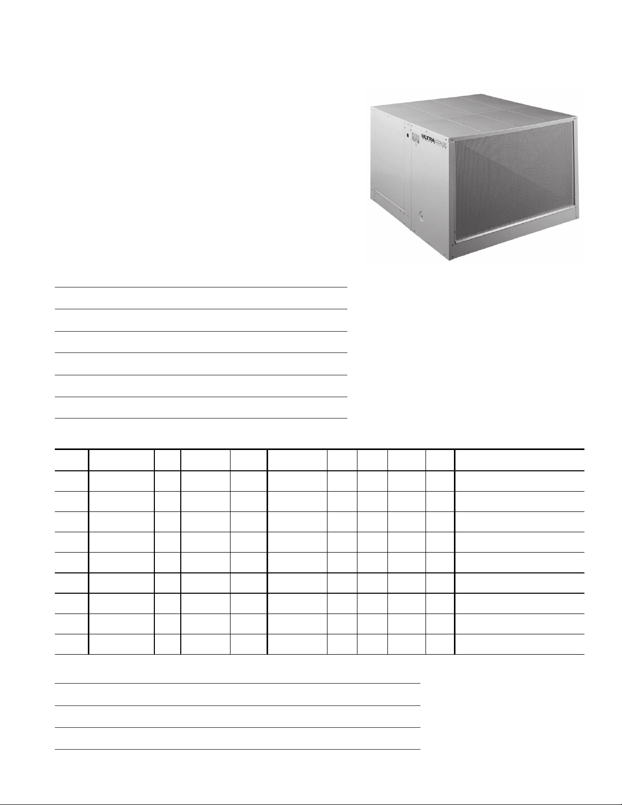
SPECIFICATIONS & SUBMITTAL DATA
FEA TURES:
• Thermostat, pumps & motor included
• Automatic dump system
• Heavy gauge galvanized steel cabinet
• Electrostatically applied polyester powder coating finish
• Thermoplastic water reservoir and plastic media shield
prevent water from contacting metal cabinet
• Stainless steel pump shaft with moisture barrier
• Long life efficient media
• Removable wet section for easier installation
• Perforated prefilter screen provides greater airflow for
better cooling
• Low maintenance and trouble free
• Made in the U.S.A.
Project
Location
Architect
Engineer
Contractor
Submitted By Date
Ref.
No.
1
2
3
4
5
6
Cooler
Model No.
Qty. CFM
Static
Pressure
MODELS
AD1C51 AD2C51
AS1C51 AS2C51
AD1C51-12 AD2C51-12
AS1C51-12 AS2C51-12
AD1C71 AD2C71
AS1C71 AS2C71
AD1C71-12 AD2C71-12
AS1C71-12 AS2C71-12
AU1C71-12 AU2C71-12
Motor HP Speed Volts Phase Optional Acce s ories
7
8
9
Notes
CHAMPION COOLER
5800 Murray, Little Rock, AR 72209
1-800-643-8341
info@championcooler.com
3-08
Page 2

C
EAE
C
R
N
J
E
Model No.
AD1C5
1
AD2C5
1
AS1C51
1
AS2C5
AD1C51-12
AD2C
51-12
AS1C51-12
1-12
AS2C5
AD1C71
AD2C7
1
AS1C71
1
AS2C7
AD1C71-12
71-12
AD2C
AS1C71-12
AS2C7
1-12
AU1C71-12
1-12
AU2C7
B
H
W
Y X
D
S
A
F
G
E
B
K
L
FRONT VIEW SIDE VIEW TOP VIEW
CABINET DIMENSIONS*
General
Dimensions
Duct
Opening Location
Wate r
Service
Location
H W D A B C E F G S J K L X Y R N Dia. Wid th Shaft Op er. Ship.
28 42 45 17 3/417 3/41 1/212 1/813 5 3/420 3/83 9/1617 14 1/1618 1/426 3/425 7/819 1/1653 16 16 3/41 258 209
28 42 45 17 3/417 3/41 1/212 1/813 5 3/420 3/83 9/1617 14 1/1618 1/426 3/425 7/819 1/1657 16 16 3/41 258 209
28 42 49 17 3/417 3/41 1/212 1/817 5 3/424 3/83 9/1617 18 1/1622 1/426 3/425 7/823 1/1653 16 16 3/41 278 219
28 42 49 17 3/417 3/41 1/212 1/817 5 3/424 3/83 9/1617 18 1/1622 1/426 3/425 7/823 1/1657 16 16 3/41 278 219
34 5/842 48 19 3/419 3/41 1/211 1/813 5 3/420 3/83 9/1617 14 1/1618 1/429 3/428 7/819 1/1664 20 16 3/41 300 251
34 5/842 48 19 3/419 3/41 1/211 1/813 5 3/420 3/83 9/1617 14 1/1618 1/429 3/428 7/819 1/1667 20 16 3/41 300 251
34 5/842 52 19 3/419 3/41 1/211 1/817 5 3/424 3/83 9/1617 18 1/1622 1/429 3/428 7/823 1/1664 20 16 3/41 327 267
34 5/842 52 19 3/419 3/41 1/211 1/817 5 3/424 3/83 9/1617 18 1/1622 1/429 3/428 7/823 1/1667 20 16 3/41 327 267
34 5/842 52 19 3/419 3/41 1/211 1/817 5 3/424 3/83 9/1617 18 1/1622 1/429 3/435 3/1616 3/467 20 16 3/41 327 267
Electrical
Service
Location
Drain
Location
Module
Length
To p P an
Length
Belt
Length
Blower Wheel
We ight
(lbs.)
ELECTR ICA L SPECIFIC ATION S CFM * * * INCH ES S TATIC PR ES S URE
Models HP Speeds Phase Volt s Amps** 0" 0.1" 0.2" 0.3" 0.4" 0.5" 0.6"
1
AD1C5
1
AS1C5
AD2C51
1
AS2C5
AD1C51-12
AS1C5
1-12
AD2C51-12
1-12
AS2C5
AD1C71
1
AS1C7
AD2C71
AS2C7
1
AD1C71-12
AS1C7
1-12
AU1C 7
1-12
AD2C71-12
AS2C7
1-12
1-12
AU2C 7
* All Dimensions in inches.
* * Blower motor (high speed) and pumps. Amp rating is Full-Load Amperage per National Electric Code.
** * Cubic feet per minute.
3/4 2 1 115 14.9
3788 3630 3450 3260 3020 2806 2570
3/4 2 1 230 7.5
3/4 2 1 115 14.9
3606 3472 3317 3135 2918 2661 2379
3/4 2 1 230 7.5
12 111517.1
5024 4820 4630 4450 4280 4100 3900
1 2 1 230 8.6
12 111517.1
4941 4747 4572 4394 4208 3996 3749
1 2 1 230 8.6
 Loading...