

Page 1

1
UBGHFFJ60SS
GB
UBGHDFFJ60SS
Page 2

2
[]02 2x
[]03 1x
[]01 x 1
[]04 x 1
[]05 x 1 set
[]06 x 1
[]07 x 4
[]09 x 4
[]10 x 1
[]08 x 4
Page 3

3
Built-in Gas Hob
Installation
GB
24
UBGHFFJ60SS
UBGHDFFJ60SS
Page 4

4
GB
Let's
get started...
Getting started...
05
Before you start
06
Safety
07
In more detail...
09
Product functions
Operation
Care and maintenance
Troubleshooting
Recycling and disposal
Technical and legal information
10
13
15
15
16
Appendix
Installation
11
23
Page 5

5
Getting
Started...
Getting started...
GB
Before you start
Safety
06
07
Page 6

6
Getting started...
GB
Before you start
Tools required
Before you start
Check the package and make sure you have all of the parts
listed.
Decide on the appropriate location for your product.
or handling to prevent personal injury or damage to the
product.
ordering replacement parts.
If you sell the appliance, give it away, or leave it behind
when you move house, make sure you also pass on this
manual so that the new owner can become familiar with the
appliance and its safety warnings.
SILICON
E
To avoid the risks that are always present when you use
an electrical appliance it is important that this appliance is
installed correctly and that you read the safety instructions
carefully to avoid misuse and hazards. please keep this
instruction booklet for future reference and pass it on to any
future owners. after unpacking the appliance please check
that it is not damaged. If in doubt, do not use the appliance but
contact Customer Services on 0344 800 1128 (UK),
014475261 (Ireland)
Page 7

7
Getting
started...
GB
Safety
These instructions are for your safety. Please read through
them thoroughly prior to installation and retain them for
future reference.
This appliance complies with all current European safety legislation,
however, the Manufacturer must emphasise that this compliance does
not prevent the surfaces of the appliance from heating up during use and
remaining hot during its operation.
Accessible parts may become hot during use. Young children should be kept
away. Care should be taken to avoid touching the appliance (e.g hob, cooker).
The Manufacturer highly recommends that this appliance be kept out of the
reach of babies and small children.
Children should be supervised to ensure that they do not play with the
appliance.
This appliance is not intended for use by persons (including children) with
reduced physical sensory, or mental capabilities, or by those who lack
experience and knowledge, unless they have been given supervision and
instruction concerning the use of the appliance by a person responsible for
their safety.
in accordance with the current wiring regulations. An all-pole disconnection
switch having a contact separation of at least 3 mm in all poles should be
Damaged power cables should be replaced by a competent person or
Make sure that the power cord is not caught under or in the appliance and
avoid damage to the power cable.
Do not allow the electric cables to touch the hot parts of the appliance.
Do not install the appliance outdoors in a damp place or in an area which
may be prone to water leaks such as under or near a sink unit. In the event
of a water leak allow the machine to dry naturally.
Please dispose of the packing material carefully.
• All installation work must be carried out by a
qualified Gas Safe registered engineer.
• This appliance must be installed correctly by a
manufacturer’s instructions.
Page 8

8
Getting started...
GB
Safety
We also recommend that great care be taken during use and cleaning.
Read the cleaning and maintenance sections for this appliance carefully.
A steam cleaner is not to be used.
The appliance is not intended to be operated by means of external timer or
separated remote-control system.
The appliance is for domestic use only.
When a cooking zone has been on for a long time, the surface remains hot
for some time afterwards so do not touch the metal surface.
Do not leave hot oils or fats unattended as they may catch light.
The Manufacturer declines all liability for personal or material damage as a
result of misuse or incorrect installation of this appliance.
Page 9

9
In more detail...
In more
detail...
GB
Product functions
Operation
11
Care and maintenance
Troubleshooting
15
Recycling and disposal
Technical and legal information
16
10
13
15
Page 10
GB
IE
In detailmore ...
GB
Product functions
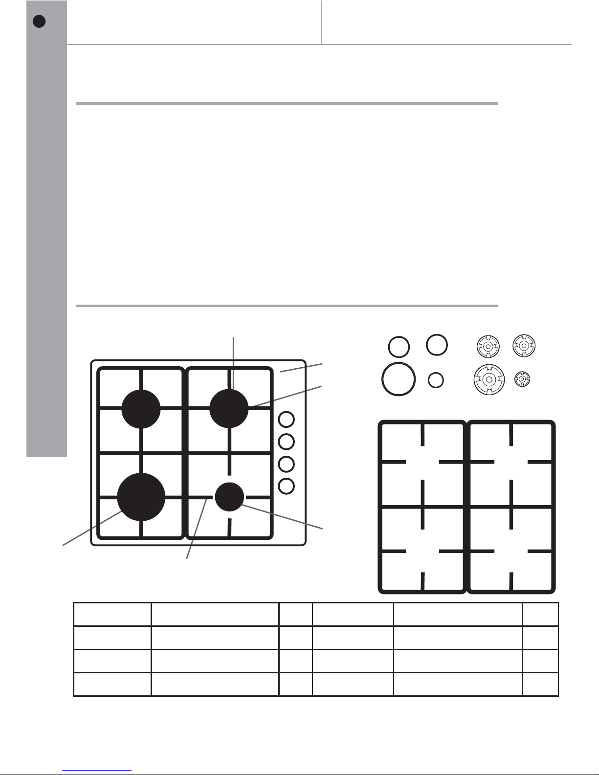
Control elements
Caution This diagram may be slightly different from the layout of the appliance: .
Operation
• 4 x Burners: Four zones of cooking.
• Flame safety device (FSD): Stops the gas supply to the gas hob when
the fame goes out.
• auto - ignition
• LPG conversion kit supplied.
Reference Description Qty Reference Description Qty
A Auxiliary burner 1 D Panel 1
B Semi rapid burner-
Burner Cap
4
C
F Pan Support 2
F
A
B
C
D
E
E
F
E
2
Large burner
1
10
Page 11
11
In more detail...
GB
Operation
Caution
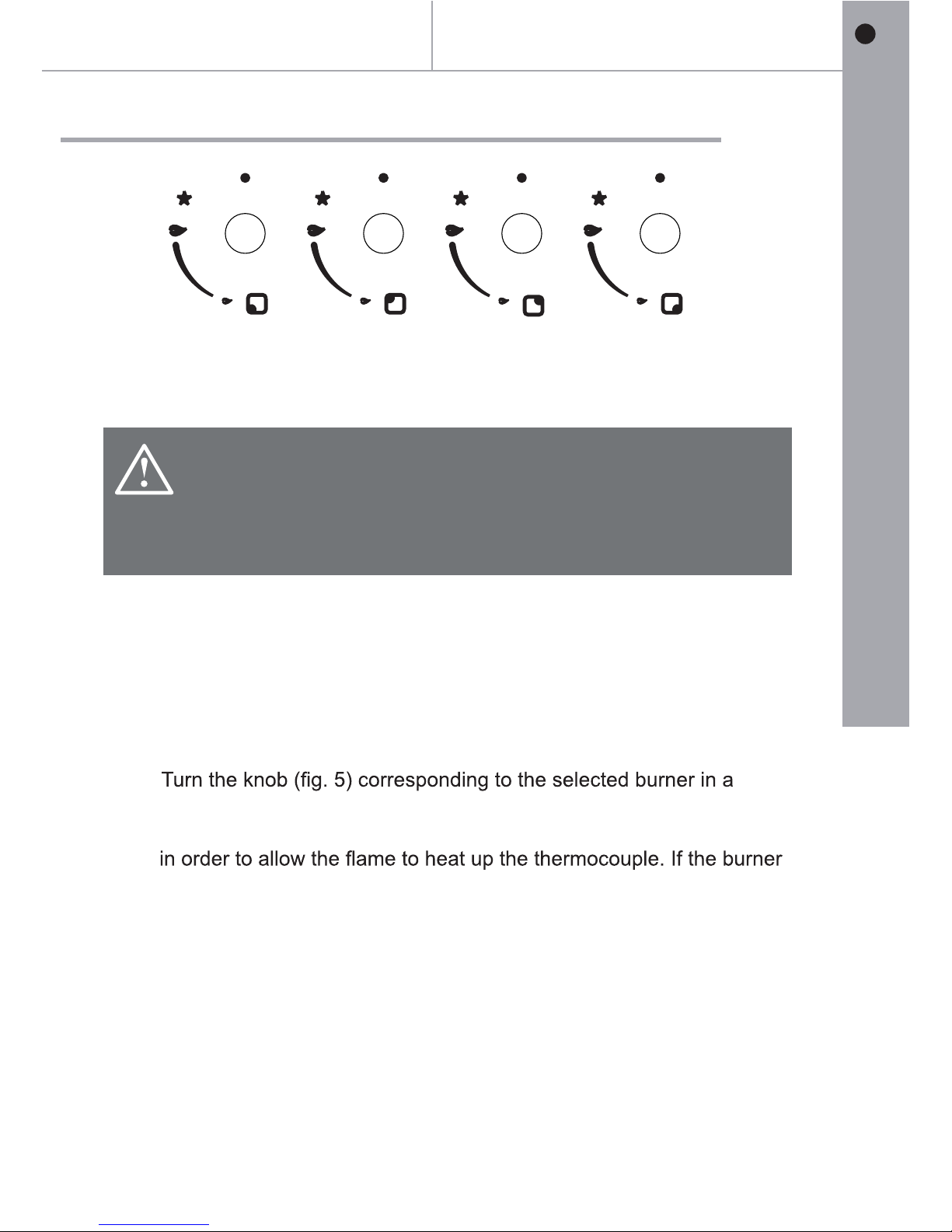
• If there is no electric current you can light the burners with
piezo electric spark gas ignitor.
• The burners can only be lit with safety thermocouples when
the knob is on MAXIMUM.
Operation
Use of the burners
>
Automatic electric ON switch for burners with safety device“”
()thermocouples
•
counter clockwise direction so that the knob is at MAXIMUM-.
•
Once the burner is lit keep the knob pressed in for about 10 seconds,
goes out when the knob is let go repeat the operation,.
On the control panel fg 4 to the left of every knob there is a diagram to(.)
indicate the burner to which the knob in question refers The burners can.
be switched on in several ways according to the type of appliance and its,
individual features.
Page 12
12
GB
IE
In more detail...
GB
Operation
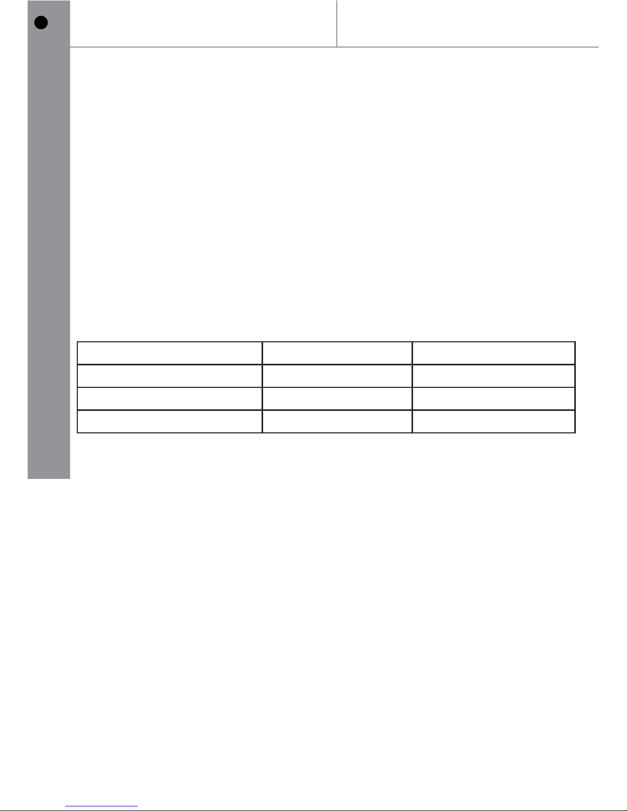
NOTE:
>
Burner Minimum Diameter Maximum Diameter
180mm 240mm
Medium (semi-rapid) 140mm 180mm
Small (auxiliary) 120mm 140mm
WARNING
If you use a saucepan that is smaller than the recommended diameter
the ame will spread beyond the bottom of the vessel, causing the
handle to overheat.
Never leave empty pot or pans over a lit burner.
Do not use tools for gill cooking on gas on glass hobs.
The use of a gas cooking appliance produces heat and humidity in the
place where it is installed.
Therefore, you need to ensure the place is well ventilated, keeping the
natural ventilation openings clear and using a mechanical ventilation
device/ ue or electric fan.
Intensive or prolonged use of the appliance may require additional
ventilation, such as opening a nearby window or increased ventilation
efency obtained by increasing the power of the mechanical ventilators,
where applicable.
Advice for the best use of the burner:
When boiling point is reached, turn the knob to MINIMUM.
Always use pans with a lid .
>
>
>
>
Large (rapid)
Page 13
13
In
more
detail...
GB
Care and maintenance
Appliance cleanliness
>
>
>
:
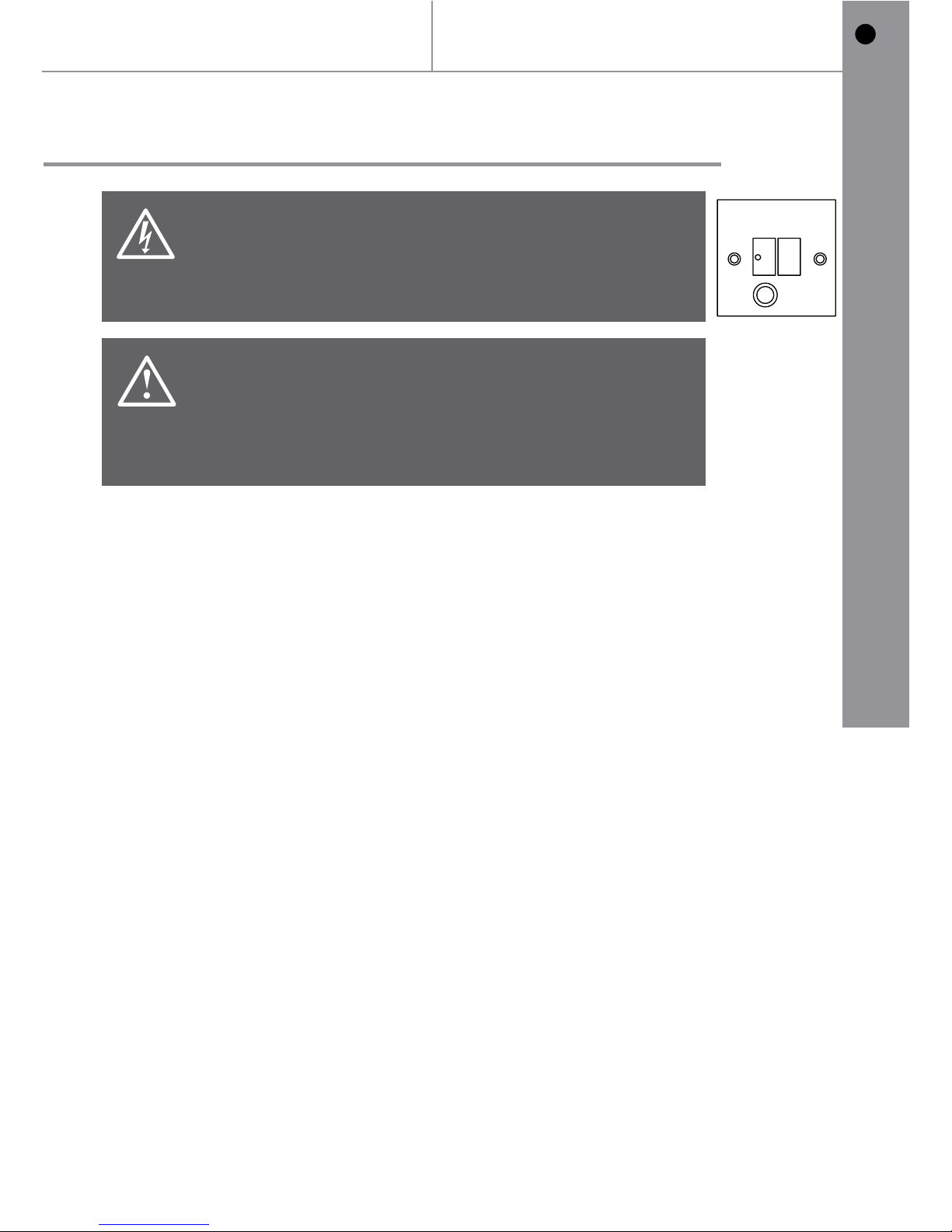
Warning
Always switch off the electricity supply before
performing maintenance work. In the event of a fault,
contact customer services.
Caution
• Use soapy water and a cloth for cleaning. Never
use abrasive powders.
• Avoid banging pots and pans down on the hob.
• Do not leave any empty pan on the heating zone.
FUSE
OFF
>
Cleaning the hob panel.
Regularly wipe over the hob top with a soft cloth well rung out in warm water
to which a little washing up liquid has been added. Avoid use of the following:
1) Household detergent and bleaches. 2) Soap impregnated scouring pads.
3) Steel wool. 4) Bath/sink stain removers.
Cleaning the pan supports.
If washing them by hand, take care when drying them as the enameling and
dieing process occasionally leaves rough edges. If necessary remove
stuborn stains using a paste cleaner.
Cleaning the burners.
The burner caps and crowns can be renoved for cleaning. Wash the burner caps and crowns using hot soapy water and remove marks using a mild
paste cleaner.
A well moistened soap impregnated steel sool pad can be used with caution
if the marks are particularly difcult to remove. After cleaning make sure to
dry using a soft cloth.
Note: It is very important to keep the thermocouples and the ignition candles
in a clean condition to prevent problems lighting and maintaining a ame on
the burners.
The appliance should be cleaned after use.
Wipe the inner and outer surface of the appliance and its accessories
with wet cloth.
Any liquid overowing from the pan must always be removed with
a cloth.
The surface of the hob may be easily cleaned as follows
Page 14
14
GB
IE
In more detail...
GB
Replacement of parts
Warning
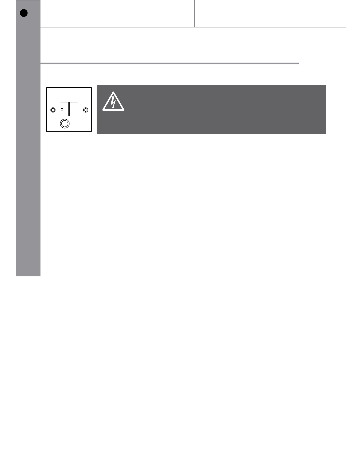
Always switch off the electricity supply before
performing maintenance work. In the event of a fault,
contact customer services.
Care and maintenance
FUSE
OFF
Page 15
15
In
more
detail...
GB
Troubleshooting
The following circumstances may not be a problem. Do not contact the
If your appliance is still not functioning properly after making the above
checks, please contact customer services.
1. Check that the mains supply has not been switched off.
2. Check that the fuse in the spur has not blown.
3. Ensure that the burner components are not excessively soiled as
this can lead to ignition problems.
Do not take the appliance apart yourself, as you may damage the hob.
Before calling After Sales Service, please do the following:
1. Check that the appliance is correctly connected.
2. Read the failure text above. If you are still unable to solve the
problem, switch off the appliance, do not try to take it apart
and call customer services.
Troubleshooting
Recyling and disposal
Environmental protection
Waste electrical products should not be disposed of with household waste.
Please recycle where facilities exist. Check with your Local Authority or
retailer for recycling advice.
The symbol on the product or its packaging indicates that this
product cannot be treated as normal household waste. This
product must be handed over to an electric and electronic
equipment collection point for recycling.
On ensuring that this product is disposed of correctly, you will help to
avoid possible negative consequences for the environment and public
health, which could occur if this product is not handled correctly. To receive
more detailed information about recycling this product, contact your local
government, domestic waste disposal services or the outlet where the
product was bought.
Page 16
16
GB
IE
In detail...more
G
technical and legal
information
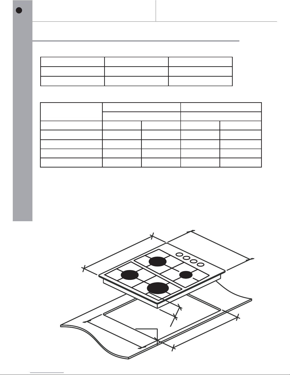
Technical data
Power Supply V/Hz 220-240 Vac 50Hz
Gas Pressure mbar G20 / G30 / G31
External Dimensions HxDxW mm 110x500x580
NG 12H 20(() LPG I3 28 30 37(+ ( - / )
Injector Dia. (mm) and kW Injector Dia. (mm) and kW
Gas Category Dia kW Dia kW
Wok Burner 1.24 3 0. 0.88 30.
Rapid Burner 1.14 2.5 0.81 2.5
Semi rapid burner 0.98 1.75 0.69 1.75
Auxiliary burner 0.74 1.0 0.51
1.0
Width: 580mm
Depth: 500mm
Cut-out Dimensions
Width: 555mm Depth: 475mm
Overall Dimensions:
580
500
475
555
4 R15-
110
Page 17
17
In more detail...
GB
Technical and legal
information
All installation work must be carried out by a
Before connecting the mains supply ensure that
the mains voltage corresponds to the voltage on
the rating plate inside the cooker hood.
Warning: THIS APPLIANCE MUST
BE EARTHED.
Mains Supply could be connected to the Mains Voltage by Direct
Connection
Direct Connection
If the appliance is being connected directly to the mains an
omnipolar circuit-breaker must be installed with a minimum
opening of 3mm between contacts.
If the cable is damaged or to be replaced, the operation must be
avoid any accidents.
The installer must ensure that the correct electrical connection has
been made and that it complies with wiring diagram.
The cable must not be bent or compressed.
The cable must be checked regularly and replaced by authorized
technicians only.
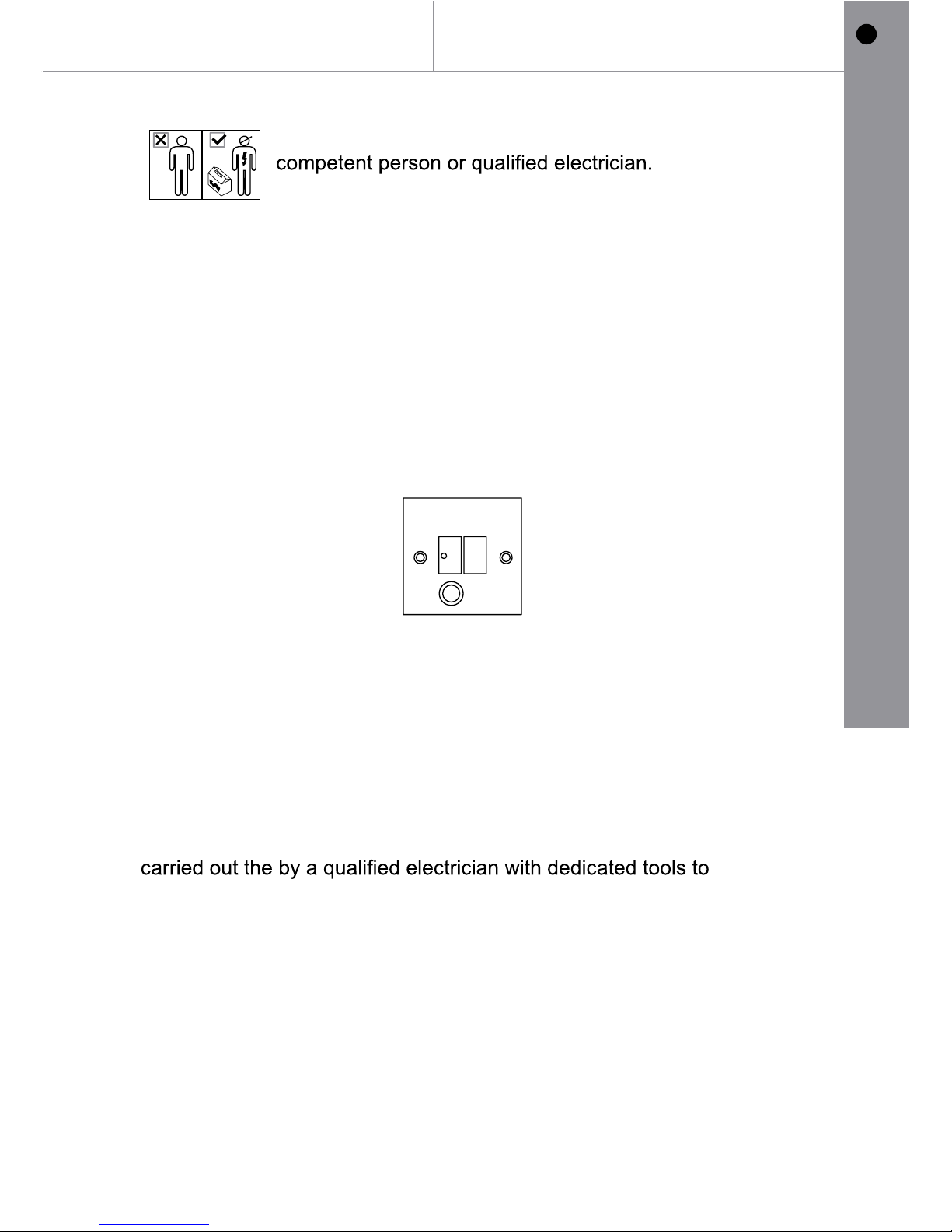
DOUBLE POLE SWITCHED
FUSED SPUR OUTLET
USE A 3AMP FUSE
FUSEO N
Page 18
18
GB
IE
In more detail...
GB
Electrical Requirements
Any permanent electrical installation must comply with the latest
I.E.E. Regulations and local electricity company regulations. For
roll of the National Inspection Council for Electrical Installation
Contracting (NICEIC) should undertake the electrical installation.
Electrical Connection
Before connecting the mains supply ensure that the mains
voltage corresponds to the voltage on the rating plate inside
the appliance.
WARNING: THIS APPLIANCE MUST BE EARTHED
The appliance is supplied with a 3-core mains cable and must be
connected to the electricity supply via a double pole switch having
a 3mm minimum contact gap on each connector.
For UK only
A Switched Fused Connection Unit to BS 1363 Part 4 is
recommended.
The fuse must be rated at 3 Amps.
The wires in the mains lead are coloured in accordance with the
following code:
Brown = L - Live
Blue = N - Neutral
Green/Yellow = - Earth
The connection point must be placed in a position adjacent to the
appliance so as to be readily accessible for an engineer in the
event of a breakdown.
Disconnect the appliance from the mains supply before
carrying out any kind of maintenance or cleaning.
Technical and legal
information
Page 19
19
In
more
detail...
GB
Installation Guidelines
Gas Supply Requirements (UK and ROI)
This installation must comply with the Gas Safety Regulations 1984.
The connection to the gas supply must comply with all current
regulations in force.
We are not legally able to offer advice on the installation of gas
appliances to non Gas Safe registered personnel.
Ventilation
All rooms require a window or equivalent (e.g. a door) which can be
opened. Some rooms require a permanent vent or extractor in addition
to a window (see below).
This unit must not be used in a room which is less than 5m
3
.
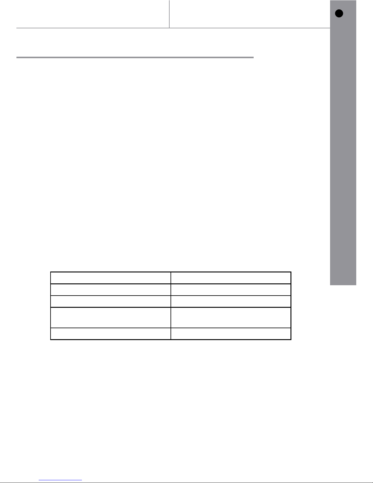
The following table details the requirements based on the kitchen
volume (L x W x H) in m
3
.
The above requirements also allow use of a gas oven and grill but if
there are any other fuel burning appliances in the same room, consult
the relevant British Standard (BS5440) or Gas Safe manual.
The above requirements also allow use of a gas oven and grill but if
there are any other fuel burning appliances in the same room, consult
the relevant British Standard (BS440) or Gas Safe document.
What you should do if you smell gas?
Switch off the gas supply
Open doors and windows
Call Transco 0800 111 999
Room Volume (m3)A ir vent required (cm3)
5 100
6 to 105 0
6 to 11
No permanent vent required if a
door opens to the outside
11 or more None required
Technical and legal
information
A
Page 20
20
GB
IE
In more detail...
GB
Gas connection
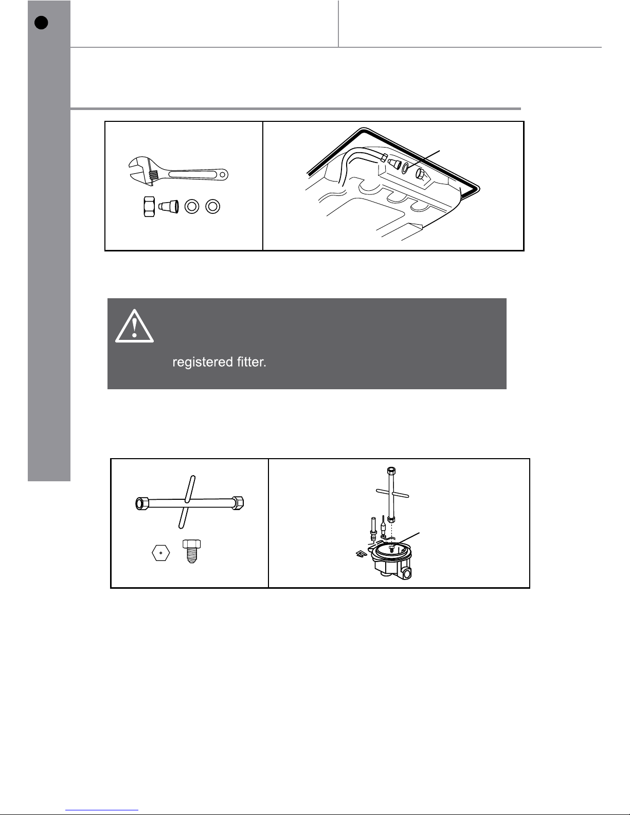
Changing the nozzles
NOTE: The LPG nozzles are provided in a separate bag marked “LPG” and
if they are changed and the natural gas jets retained then the label should be
changed to “NATURAL”.
Lift up the burners and unscrew the nozzle using an dedicated tool and
replace the nozzles with those designed for LPG gas supply.
Caution
The hob installation and burner changes must be
carried out by a competent person. ie a Gas Safe
02
[08] x4
x1
[08]
01
[09] x1
x1
[09]
Technical and legal
information
should mark the appliance to show which injectors are being used.
Note: When the injectors have been changed the gas technician
(see table on page 16)
Page 21
21
In more detail...
GB
Regulation of burners
:
Technical and legal
information
Regulation of burners
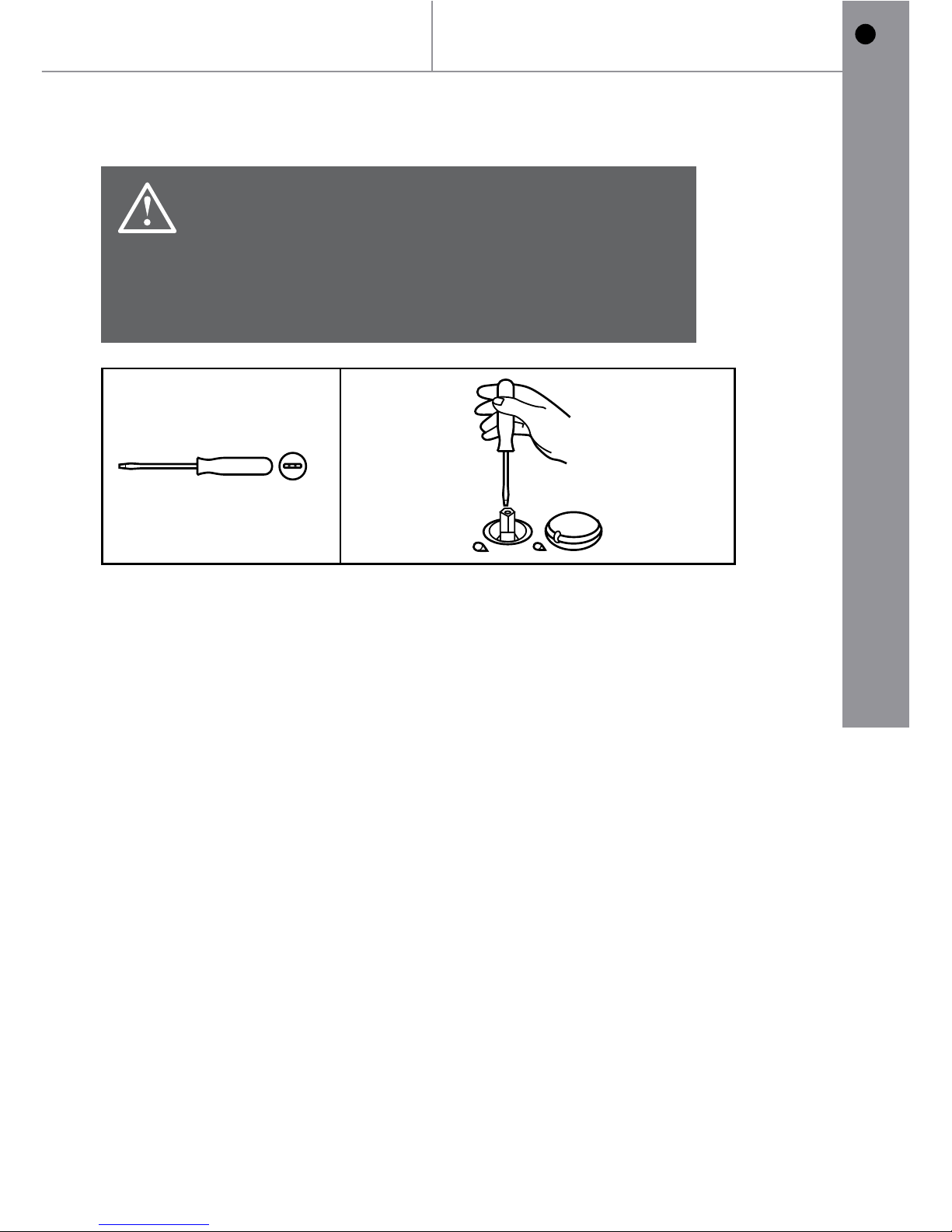
Regulation of the “MINIMUM” position on the burners.
To regulate the minimum position on the burners, follow the procedure below:
1. Turn on the burner and turn the knob to its MINIMUM position (small
ame).
2. Remove the knob from the tap set for standard pressure. The knob is
found on the bar of the tap itself.
3. Place the tap bar on the work top, use a small screwdriver that ts the
(gold) screws located at the lower part of the tap and turn the xing
screw to the right or left until the ame of the burner is regulated in the
most suitable manner to MINIMUM.
4. Make sure that the ame does not go out when changing the position
quickly from MAXIMUM to MINIMUM position.
Caution
The regulation described can only be carried out with
burners that use methane gas and city gas (where
available), whereas the screw must be fully tightened
in a clockwise direction on burners using liquid gas.
01
Page 22
22
GB
IE
In more detail...
GB
Technical and legal
information
The Manufacturer has a policy of continuous product improvement, it
necessary without prior warning.
Page 23

23
Appendix...
GB
Appendix
Page 24
Appendix...
GB
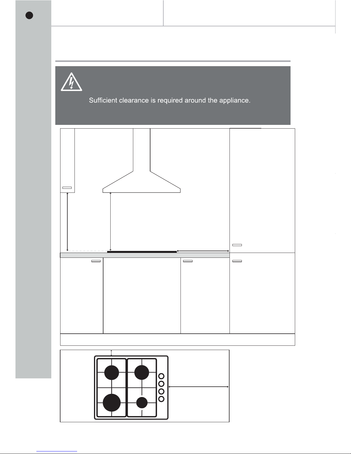
750mm
At least
300mm
750mm
60mm
At least
300mm
Installation
Clearance
Warning
Good ventilation is required around the appliance for easier
dissipation of heat and low power consumption.
The gap between the hob and any cupboard above it
should be at least 750mm.
24
Page 25
01
02
Installation
[06] x 1
[06]
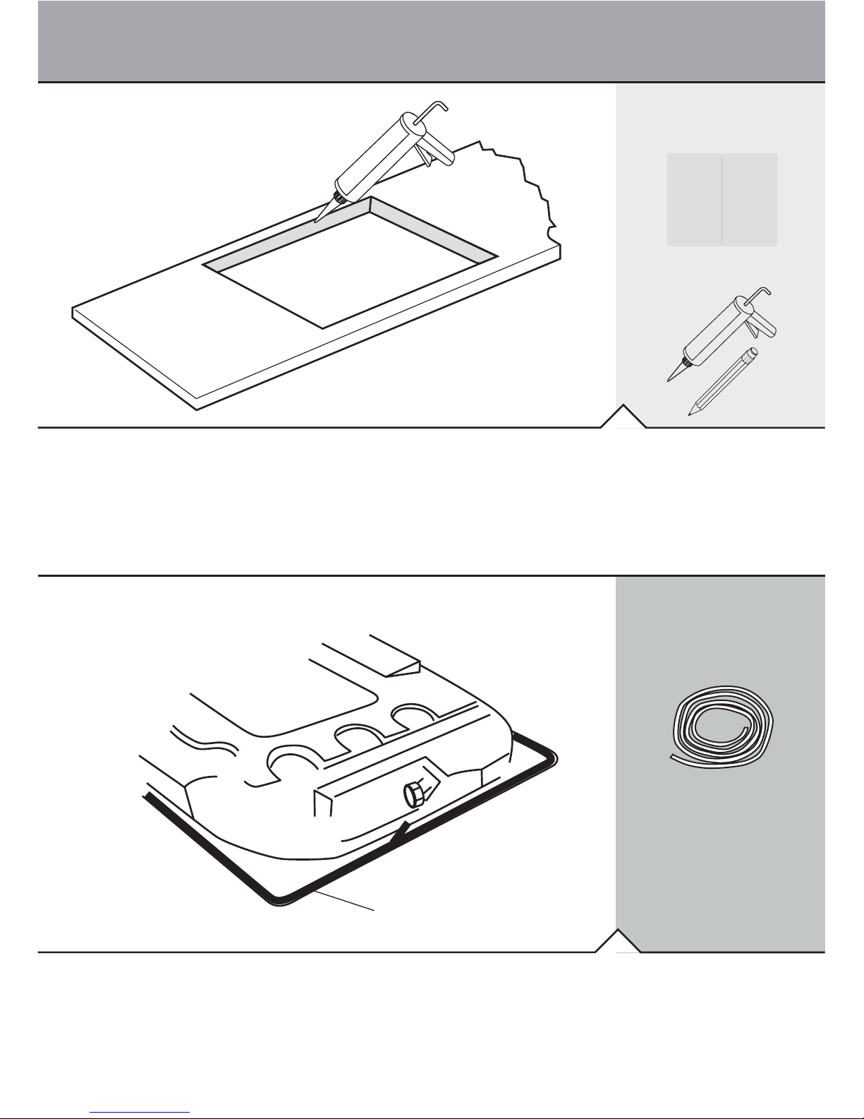
Cut out worktop to the template dimensions with suitable equipment and seal the cut
edge with appropriate sealant.
[11] x 1
TEMPLATE
TEMPLATE
SILICON
E
SILICONE
Stretch out the supplied seal along the underside edge of the hob, ensuring the
ends overlap.
25
Page 26
03
04
Installation
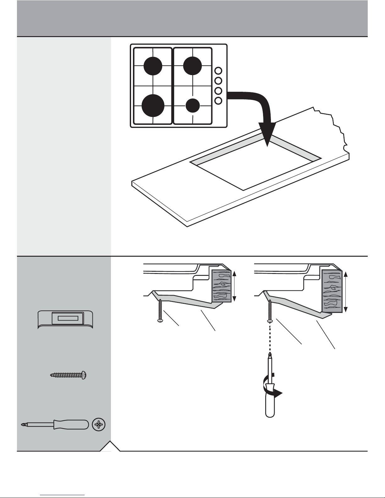
[]07 x 4
[]10 x 4
30mm
40mm
[]10
[]07
[]10
[]07
Note For electrical connection see Technical and legal information section:
Note The images above are a guide only:.
26
Page 27

27
Notes
Page 28

GB
5.5.0000025 23.09.2015
0845
Pin code 0845CQ0016:
28
 Loading...