

Page 1
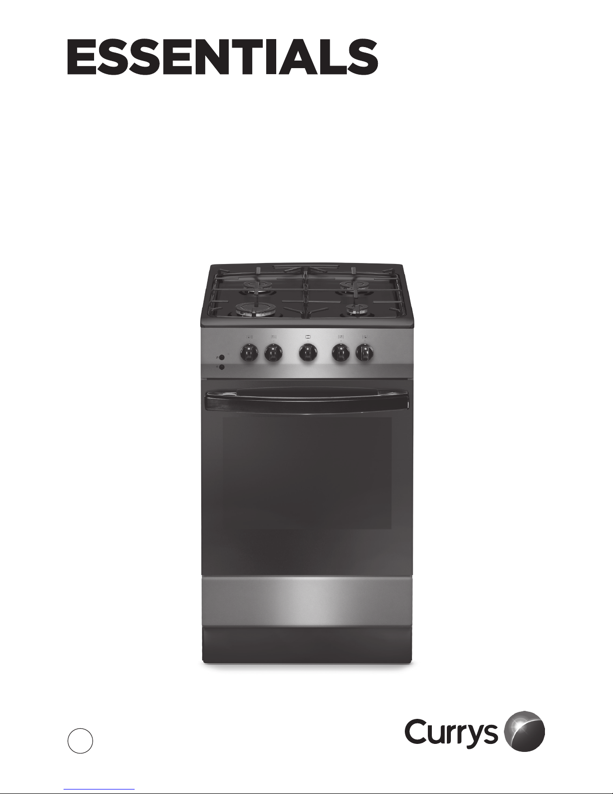
INSTRUCTION MANUAL
SINgLe OveN
CFSgSv17/CFSgWH17
GB
Page 2

Contents
Safety Warnings ............................................................................................................................ 4
Unpacking ..................................................................................................................................... 7
Product Overview ......................................................................................................................... 8
Front View ...................................................................................................................................................................8
Top View .......................................................................................................................................................................8
Control Panel ..............................................................................................................................................................9
Gas Burners .................................................................................................................................................................9
Before Using Your Cooker ............................................................................................................ 9
Using the Hob Burners ............................................................................................................... 10
Flame Failure Device ............................................................................................................................................10
If the Burner Does Not Light .............................................................................................................................. 11
If the Flame Is Irregular ........................................................................................................................................ 11
General Guidelines ................................................................................................................................................11
Using the Oven ........................................................................................................................... 12
First Time Use of the Oven .................................................................................................................................12
Oven Controls ......................................................................................................................................................... 12
Lighting the Hob Burners ................................................................................................................................... 12
Oven Temperature Chart .................................................................................................................................... 12
Shelf Positions.........................................................................................................................................................13
Adjusting the Temperature ................................................................................................................................ 14
Preheating ................................................................................................................................................................ 14
Cooking .....................................................................................................................................................................14
Cooking with the Grill ................................................................................................................ 15
First Time Use .......................................................................................................................................................... 15
Switching the Grill On .......................................................................................................................................... 15
Cooking .....................................................................................................................................................................15
Attaching the Grill Pan Handle ......................................................................................................................... 16
Cleaning Instructions ................................................................................................................. 17
Cleaning the Outside of the Cooker ............................................................................................................... 17
Cleaning the Oven Door Glass ..........................................................................................................................17
Cleaning the Inside of Your Oven ....................................................................................................................18
Cleaning the Gas Hob .......................................................................................................................................... 18
Hob Burner Parts and Pan Supports ............................................................................................................... 18
Replacing the Hob Burner Parts ....................................................................................................................... 19
Hob Controls (Gas Taps) .............................................................................................................19
Page 3

Removing the Oven Door .......................................................................................................... 20
Removing the Oven Glass .......................................................................................................... 21
Replacing the Oven Lamp .......................................................................................................... 22
Installation .................................................................................................................................. 23
Ventilation Requirements .......................................................................................................... 24
Adjusting the Feet ...................................................................................................................... 24
Moving the Cooker ..................................................................................................................... 25
Stability Device ........................................................................................................................... 25
Gas Connection ........................................................................................................................... 26
Installation for Using Natural Gas .................................................................................................................... 26
Installation for Using Liquid Petroleum Gas (LPG) ....................................................................................26
To Connect the Gas Supply ................................................................................................................................ 26
Replacement of Burner Injectors .............................................................................................. 27
To Replace the Hob Injectors ............................................................................................................................27
Adjusting the Reduced Flame Position .........................................................................................................27
To Replace the Oven Injector ............................................................................................................................ 27
Injector Size Table ....................................................................................................................... 28
Where to place the LPG Replacement Rating Plate Sticker .................................................................... 28
Electrical Connection ................................................................................................................. 29
Product Fiche and Specications .............................................................................................. 30
Energy Labels .............................................................................................................................. 31
Page 4

4
Safety Warnings
IMPORTANT SAFETY INSTRUCTIONS
READ CAREFULLY AND KEEP FOR FUTURE REFERENCE
• This appliance must be installed by a qualied Gas Safe registered
engineer (in the UK). The manufacturer is not responsible for any
damage caused by incorrect installation.
• Check whether there is any damage to the appliance after you have
unpacked it. If any damage is found, do not use the appliance and
contact the store where you purchased it.
• This appliance is for indoor domestic use only.
• The cooker is tted with a moulded mains plug. The mains plug must
remain accessible or a switch providing full disconnection incorporated
in the xed wiring.
• If the mains cable gets damaged, it should be replaced by an authorized
service agent or qualied electrician in order to avoid a hazard.
• The oven must be installed on at/level ground.
• Only operate your appliance in a dry atmosphere.
• Keep the electrical cables of your other appliances away from hot areas;
do not let them touch the appliance.
• Ensure that the appliance is switched o at the mains supply switch and
allowed to completely cool down before cleaning, replacing the oven
lamp or performing any maintenance to avoid the possibility of an
electric shock or burns.
• The use of a gas cooking appliance results in the production of heat,
moisture and products of combustion in the room in which it is installed.
Ensure that the kitchen is well ventilated especially when the appliance
is in use. Keep natural ventilation holes open or install a mechanical
ventilation device (mechanical extractor hood).
• Prolonged intensive use of the appliance may call for additional ventilation,
for example opening of a window, or more eective ventilation, for
example increasing the level of mechanical ventilation where present.
• This appliance can be used by children aged from 8 years and above and
persons with reduced physical, sensory and mental capabilities, or lack of
experience and knowledge if they have been given supervision or
instruction concerning use of the appliance in a safe way and understand
Page 5

5
the hazards involved. Children shall not play with the appliance. Cleaning
and user maintenance shall not be made by children without
supervision. Cleaning and user maintenance shall not be made by
children without supervision.
• During use the appliance becomes hot. Care should be taken to avoid
touching the parts inside the oven or the hob burners/pan stands.
• The appliance and its accessible parts become hot during use. Care
should be taken to avoid touching heating elements. Children less than 8
years of age shall be kept away unless continuously supervised.
• Unattended cooking on a hob with fat or oil can be dangerous and may
result in re. NEVER try to extinguish a re with water, but switch o the
appliance and then cover the ame e.g. with a lid or a re blanket.
• The cooking process has to be supervised. A short term cooking process
has to be supervised continuously.
• Danger of re: Do not store items on the cooking surfaces.
• When the oven is hot never touch the oven glass or any other parts that
get hot. Allow the oven to cool before touching these parts.
• Do not use harsh abrasives cleaners or sharp metal scrapers to clean the
oven door glass since they can scratch the surface, which may result in
the glass shattering.
• Before starting to use your appliance, keep curtains, tulle, paper or
ammable materials away from your appliance.
• Do not keep combustible or ammable things in, on or near the appliance.
• This appliance is for cooking purposes only. It must not be used for other
purposes, for example room heating.
• Do not use steam cleaners for cleaning the appliance.
• Do not rest any items on the open door and do not let children climb on
or stand on it.
• Take care when handling parts with glass, knocks, chips, heavy handling
and dropping could cause the glass to shatter.
• The glass oven door uses toughened glass and is designed to break into
many ‘nugget’ size pieces if it breaks. These pieces will still have sharp
edges, please handle broken glass with care.
• The appliance is not intended to be operated by means of an external
timer or separate remote-control system.
Page 6

6
• This appliance is not designed to be used with hob guards. Use of
inappropriate hob guards can cause accidents.
• Do not install your appliance behind a decorative door it may over heat.
• The cooker must not to be used with an extension lead.
• To prevent the appliance tipping, the stabilizing
bracket must be installed.
Page 7
7
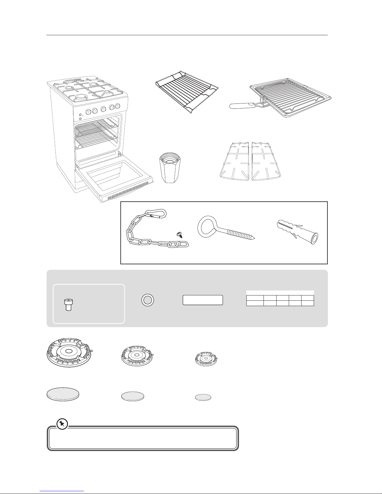
Unpacking
Remove all packaging from the unit. Retain the packaging. If you dispose of it please do so according to
local regulations.
The following items are included:
Grill Pan x 1
Grill Rack x 1
Grill Pan Handle x 1
Shelf x 2
To be used in the
oven or grill
Pan Supports (Left/Right) × 2
Large Burner Ring × 1
Large Burner Cap × 1
Standard Burner Ring × 2
Standard Burner Cap × 2
Small Burner Ring × 1
Small Burner Cap × 1
If items are missing, or damaged please contact Partmaster (UK only).
Tel: 0344 800 3456 for assistance.
LPG Conversion Kit:
Fibre Washer x 1
LPG nozzles x 5
LPG Replacement
Rating Plate Sticker x 1
LPG Nozzle
Installation Guide x 1
Large Burner
Standard Burner x 2
Small Burner
Oven Burner x 1
Type of gas
3+ G30/31 28-30/37 mbar
8056867
* All images are for indication only; please refer to your individual unit for actual item.
The Main Unit
Gas Connector x 1
BURNER NOZZLES AND THEIR DIAMETERS
Type of gas
Small
Burner
Medium
Burner
Big
Burner
Oven
Burner
G30
28-30 mbar
0.52 0.67 0.83 0.79
Wall plug x 1
Eyelet x 1Stability Chain x 1
Fixing Screw x 1
Stability Device
Page 8
8
Product Overview
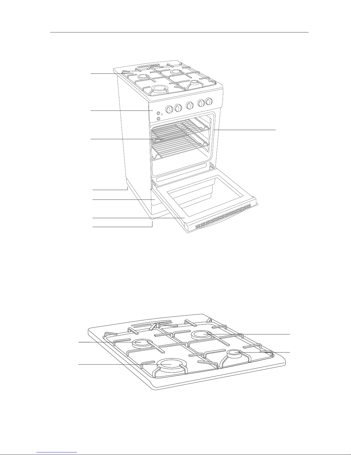
Front View
Top View
1. Standard Burners
2. Large Burner (Fast)
3. Small Burner (Simmer)
1. Gas Hob
2. Control Panel
3. Oven Shelves
4. Adjustable Feet
5. Front Flap
6. Oven Door
7. Door Seal (attached at each corner)
1
2
7
3
6
5
4
4
1
2
* All images are for indication only; please refer to your individual unit for actual item.
1
3
Page 9
9
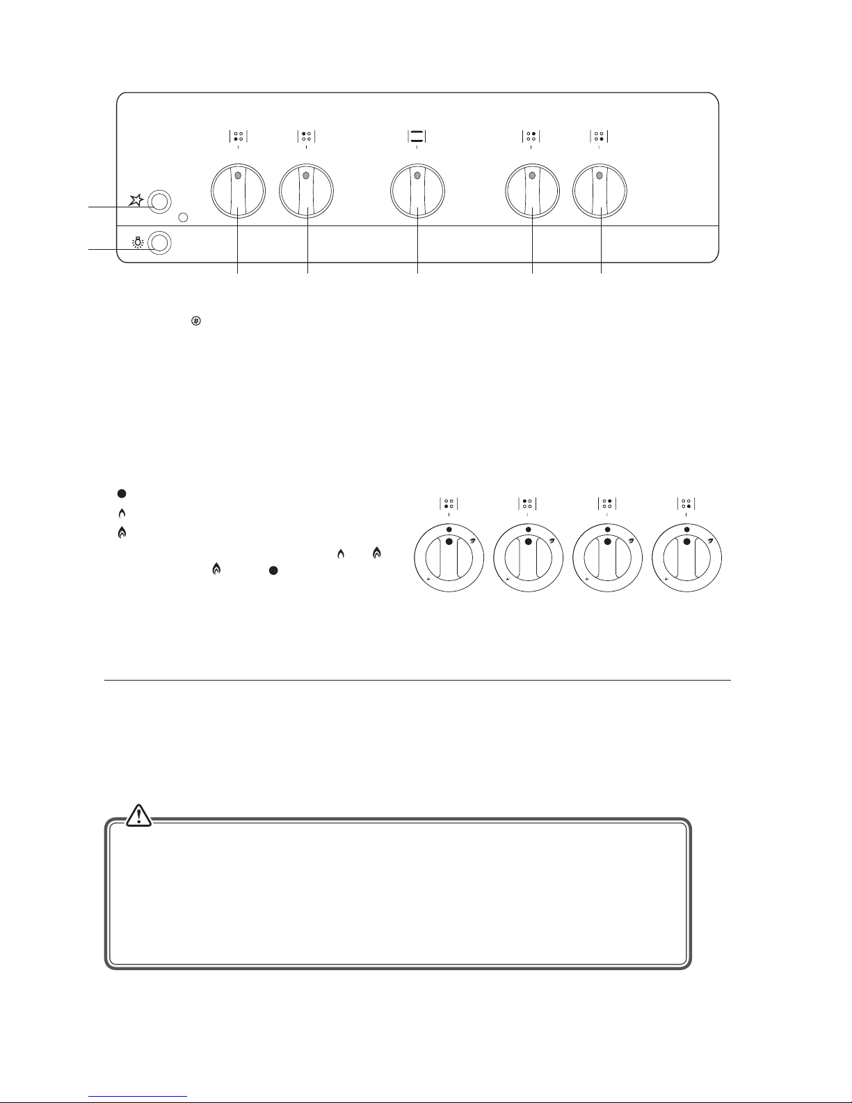
Control Panel
1. Ignition Switch
2. Oven Light Switch
3. Front Left Burner (Large) Control
4. Rear Left Burner (Standard) Control
5. Oven Control
6. Rear Right Burner (Standard) Control
7. Front Right Burner (Small) Control
Gas Burners
The relevant controls adjust the ow of gas through each of the burners.
•
= OFF
•
= Minimum Flame
•
= Maximum Flame
You can cook at any heat setting between
and ,
but never between and the position.
1
2
3 4 5
6
7
* All images are for indication only; please refer to your individual unit for actual item.
Before Using Your Cooker
Before using your new cooker, please:
• Read this instruction/installation manual, taking special note of the "Safety Warnings" section.
• Make sure all the controls are turned o.
• Turn the mains power on.
• This appliance is for cooking purposes only. It must not be used for other purposes, for example
room heating.
• The use of a gas cooking appliance results in the production of heat, moisture and products
of combustion in the room in which it is installed. Ensure that the kitchen is well ventilated
especially when the appliance is in use: keep natural ventilation holes open or install a mechanical
ventilation device (mechanical extractor hood). Prolonged intensive use of the appliance may
call for additional ventilation, for example opening of a window, or more eective ventilation, for
example increasing the level of mechanical ventilation where present.
Page 10
10
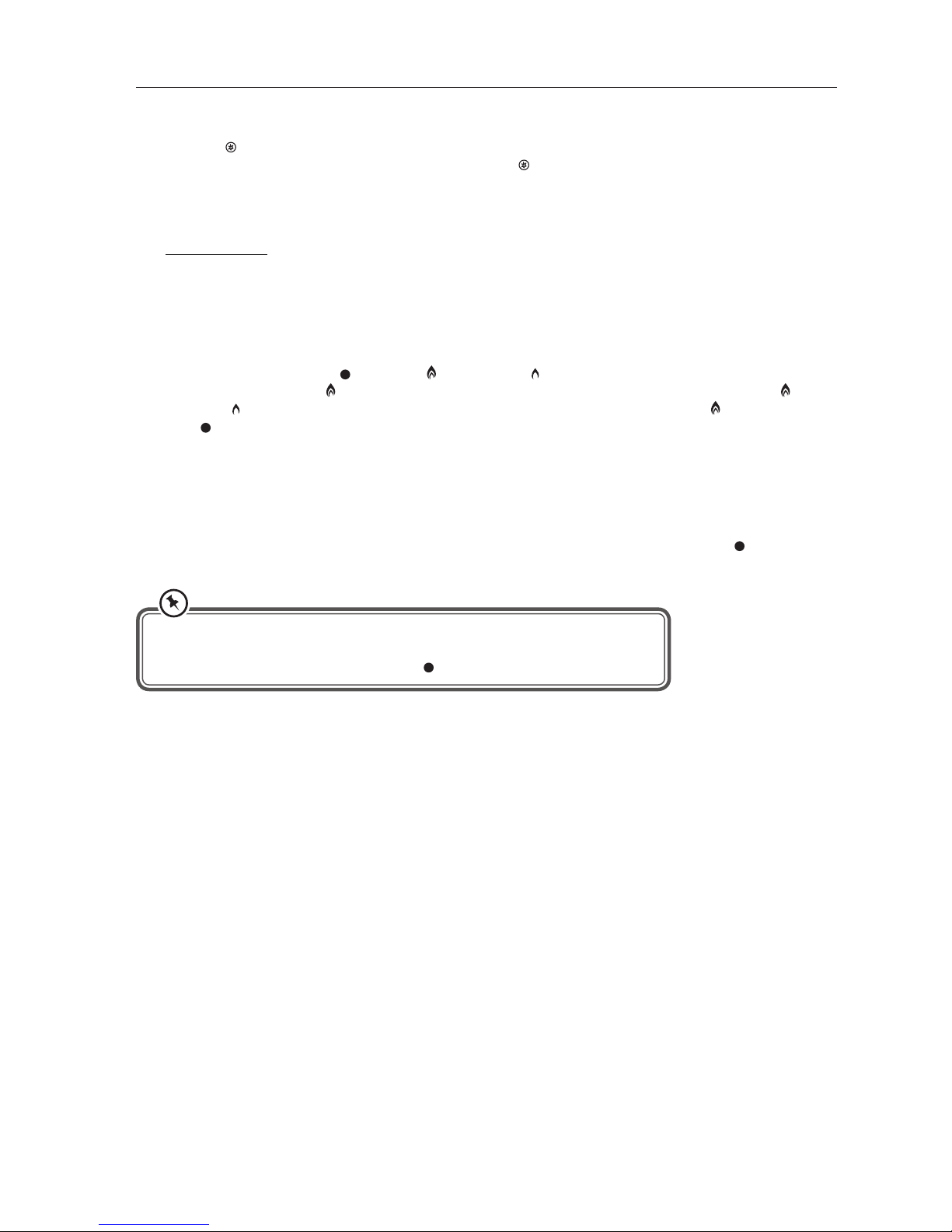
Using the Hob Burners
1. Choose the control for the burner you want to use.
2. Press the
ignition switch and at the same time press and hold the burner control in and then turn it
counter-clockwise to the maximum position. Release the Ignition switch only, once the burner is lit.
3. Continue to hold the control in for approximately 10 seconds after the burner has lit. Releasing the control
too soon will extinguish the ame due to the ame Failure device working.
Manual Ignition (in case of electricity failure)
To ignite one of the burners, press and turn the control counter-clockwise so that the control is at
its maximum position. Hold an ignition source (e.g. candle lighter, spark ignitor) close to the upper
circumference of the burner. Move the ignition source away as soon as you see a stable ame. Continue
holding the control in for approximately 10 seconds after the burner has lit. Releasing the control too soon
will extinguish the ame due to the ame failure safety feature.
The control has 3 positions: OFF (
), maximum and minimum . After you have ignited the burner
at the maximum position , you should adjust the ame length for cooking between the maximum and
minimum ame positions. You must not cook with the control between the maximum and
OFF ( ) positions.
4. After ignition, check the ames visually. If you see yellow tipped, lifted or unstable ames; turn the control o,
and once the parts have cooled suciently check the assembly of the burner rings and caps. Also, make sure
that no liquid has entered into the burner cups. If the burner ames go out accidentally, turn the burners o,
and do not try to light them again for at least one minute (to allow the gas to disperse).
5. When turning the hob o, turn the control in a clockwise direction so that the control shows
position in
line with the marking on the control panel.
Flame Failure Device
The ame Failure device (FFD) probe cuts o the gas supply to the burner if the ame is blown out.
When lighting the burner on ame failure models, hold down the control for approximately 5 to 10 seconds after
the burner has lit. Releasing the control too soon will extinguish the ame.
If the ames are accidentally extinguished, turn o the burner and do not try to light it again for at least one
minute (to allow the gas to disperse).
• If the burner does not light within 15 seconds, turn the control o and wait
for at least one minute before trying again.
• After use, always turn the controls to the
position.
Page 11
11
If the Burner Does Not Light
If the burner does not light, check that:
• The cooker is switched on at the mains supply to enable the ignition circuit to work.
• The gas is turned on.
• You have held in the control for at least 5 to 10 seconds.
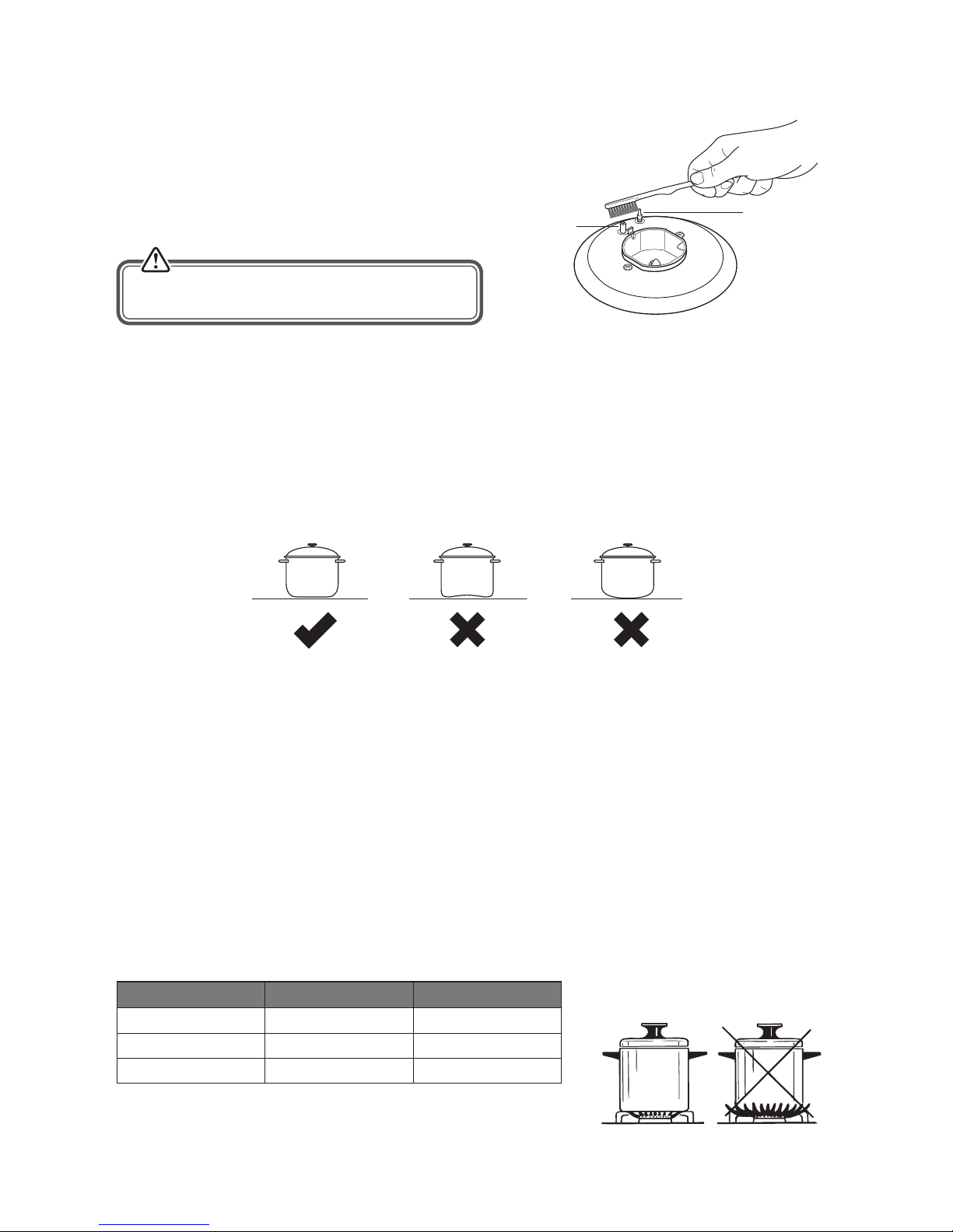
• The ignitors are sparking. If the ignitors are not sparking,
they may be dirty or wet. Clean them gently with a small
nylon brush such as a toothbrush as shown.
If the Flame Is Irregular
If the ame is yellow or irregular, check that the burner parts, including the burner cap, are:
• Clean and dry.
• Positioned correctly. See ‘Replacing the Burners’.
Flame failure
probe
Ignitor
Never operate the ignition without the burner parts
in position. You may damage the electric ignition.
* All images are for indication only; please refer to your individual unit for actual item.
• Do not let large saucepans or frying pans overlap the edges of your hob as this can deect heat onto your
worktop and damage the surface.
• Always make sure saucepans are stable. Using very heavy saucepans may bend the trivet/pan support or deect
the ame.
• Always lift the cookware when removing from the hob, do not drag.
• Always position pans over the centre of the cooking zone, and turn the handles to a safe position so they
cannot be knocked, grabbed or positioned over a burner.
• When you need to boil, simmer or fry food, rst set the temperature to the high position. Once the food
is boiling, reduce the temperature to maintain a steady ow of heat to cook your food thoroughly. Doing this
will reduce the cooking time.
• Your cooker has burners of dierent diameters. The most economical way of using gas is to choose the correct
size gas burners for your cooking pan size and to bring the ame to minimum position once the boiling point
has been reached. It is recommended to always cover your cooking pan.
• In order to obtain maximum performance from the main burners, use saucepans with the following at bottom
diameters. Using smaller saucepans than the minimum dimensions stated below will cause energy loss.
• Saucepan sizes should be as per the table shown below.
Burners Diameter Minimum Diameter Maximum Diameter
Small (Simmer) 9 cm 15 cm
Standard 16 cm 22 cm
Large (Fast) 20 cm 24 cm
General Guidelines
To get the best out of your hob, follow these simple suggestions:
• Use saucepans with thick at bottoms. Food in a saucepan with an uneven bottom will take longer to cook.
Page 12
12
Lighting the Hob Burners
1. Choose the hob burner you wish to light.
2. Press the
Ignition switch and at the same time press and hold the main hob control in and then turn it
counter-clockwise to the maximum position. Release the Ignition switch only, once the burner is lit.
3. Continue to hold the oven control in for approximately 10 seconds after the burner has lit. (You will see blue
ames through the bottom burner grid.) Releasing the control too soon will extinguish the ame due to the
ame failure safety feature.
Manual Ignition (in case of electricity failure)
To ignite the oven burner, press and turn the oven burner control counter-clockwise so that the control is at
its maximum position. Hold an ignition source (e.g. candle lighter, spark ignitor) close to the hole just to the
left of centre of the bottom of the oven. Move the ignition source away as soon as you see a stable ame.
Continue holding the control in for approximately 10 seconds after the burner has lit. Releasing the control
too soon will extinguish the ame due to the ame failure safety feature.
4. After ignition, check the ames visually. If you see yellow tipped, lifted or unstable ames; turn the control o,
and call a Gas Safe registered engineer (in the UK) to check the cooker. If the burner ames go out accidentally,
turn the burners o, and do not try to light them again for at least 90 seconds (to allow the gas to disperse).
5. When turning the oven o, turn the control in a clockwise direction so that the control shows “
” position
(o) in line with the marking on the control panel.
Using the Oven
First Time Use of the Oven
Ensure that nothing has been left in the oven and that the room is well ventilated.
Remove any insert cards or plastic bags. Before connecting the power, use a damp cloth to carefully wipe the
inner cavity wall and housing. Clean all the detachable parts in hot, soapy water before using.
Heat the oven on maximum for 45 minutes. (Please refer to the "Lighting the Oven Burner" section) There may
be a little smoke and odour upon initial start up (for about 15 mins). This is normal. It is due to the protective
substance which protects the cooker from the eects of corrosion during shipping from the factory.
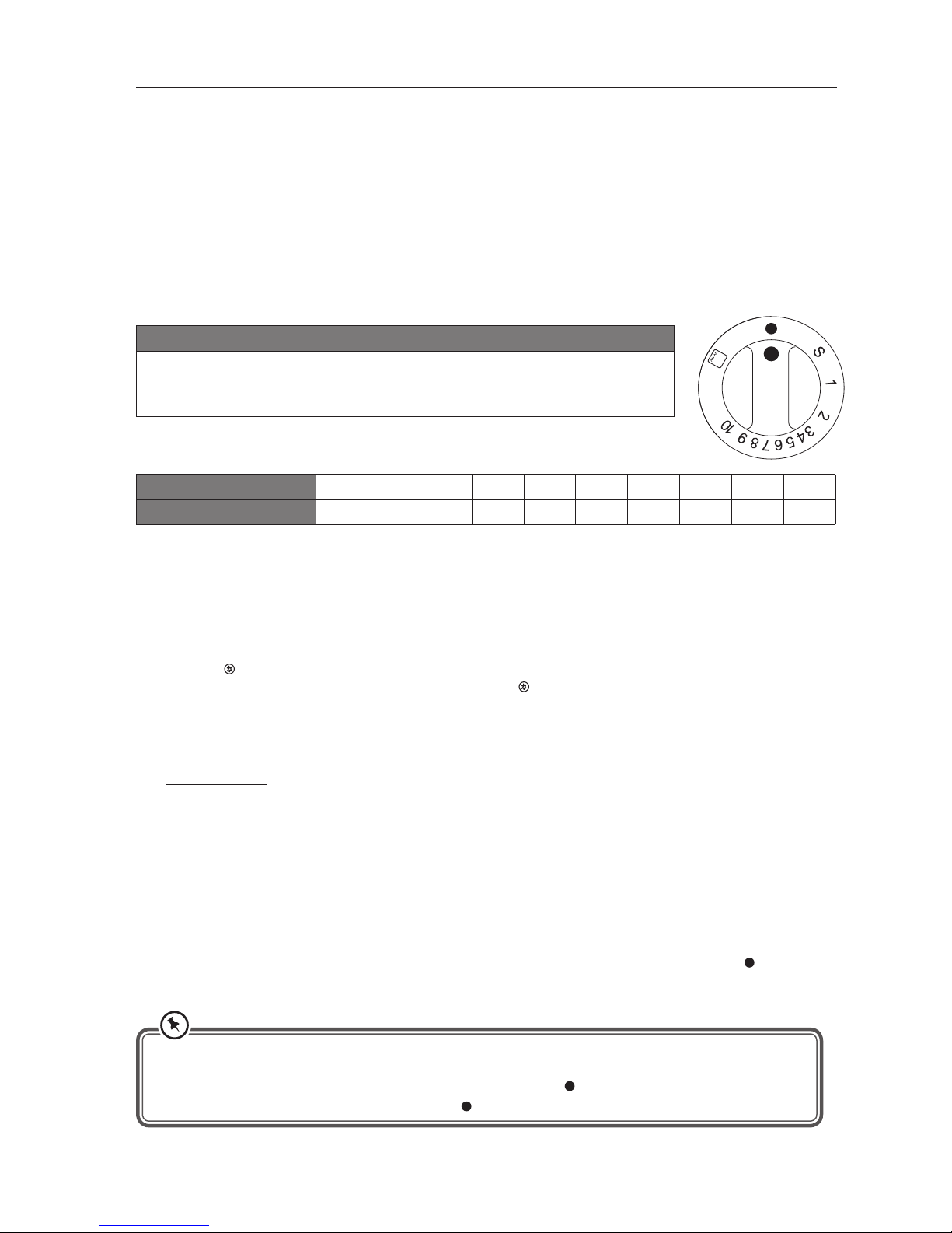
Oven Controls
Function Description
S1 2 3 4 5 6 7
8 9 10
Oven Function
Push in and turn the control anti-clockwise to your desired Gas Mark
setting.
* All images are for indication only; please refer to your individual unit for actual item.
• If the oven burner does not light within 15 seconds, turn the control o and wait for at least one minute
before trying again.
• To switch the oven burner o, turn the control clockwise to the “
” position.
• After use, always turn the oven controls to the “
” position.
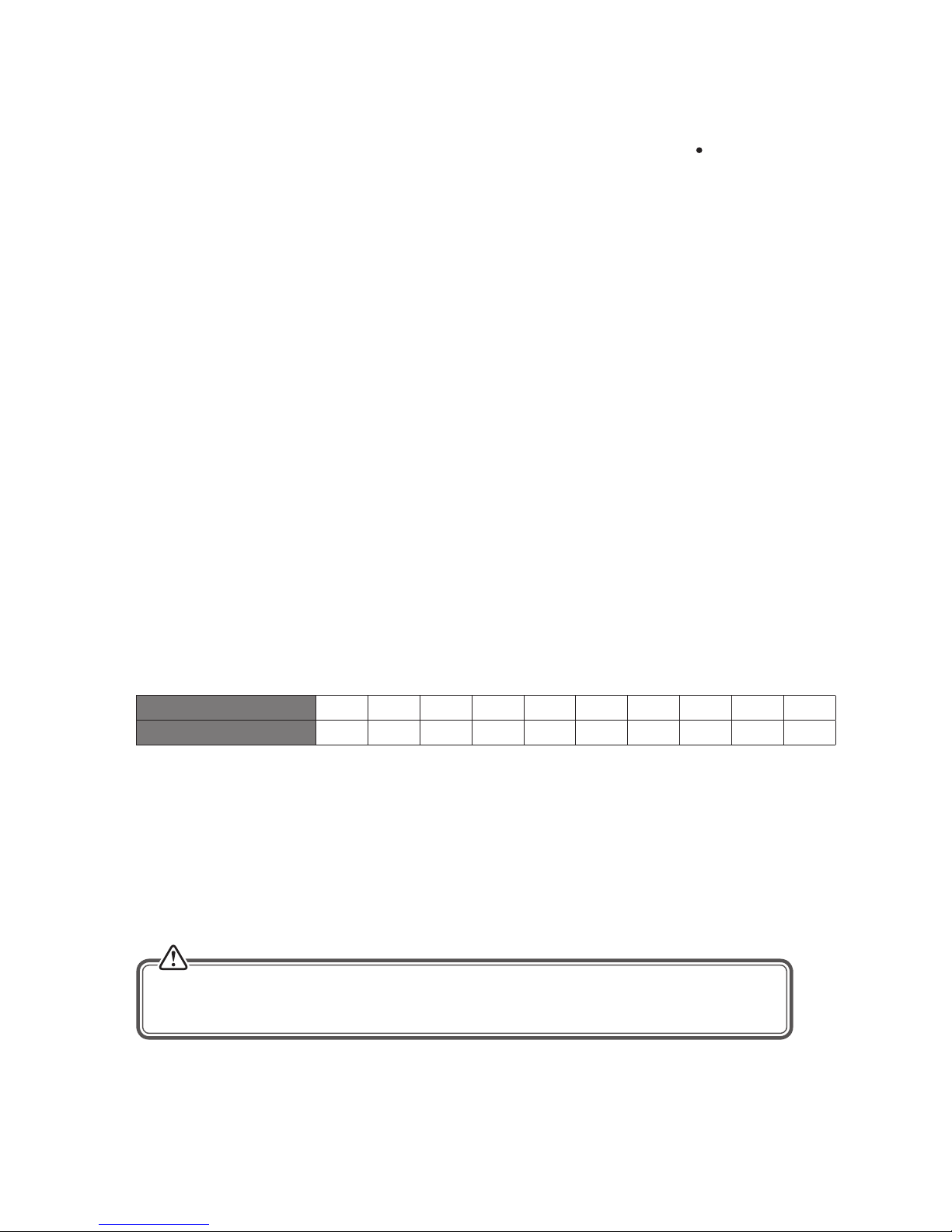
Oven setting 1 2 3 4 5 6 7 8 9 10
Temperature in °C 136 137 154 165 174 185 190 203 215 237
The temperatures above are a guide, if accurate temperatures are required then this should be checked using an
oven thermometer available at most cookware shops.
Oven Temperature Chart
Page 13
13
Shelf Positions
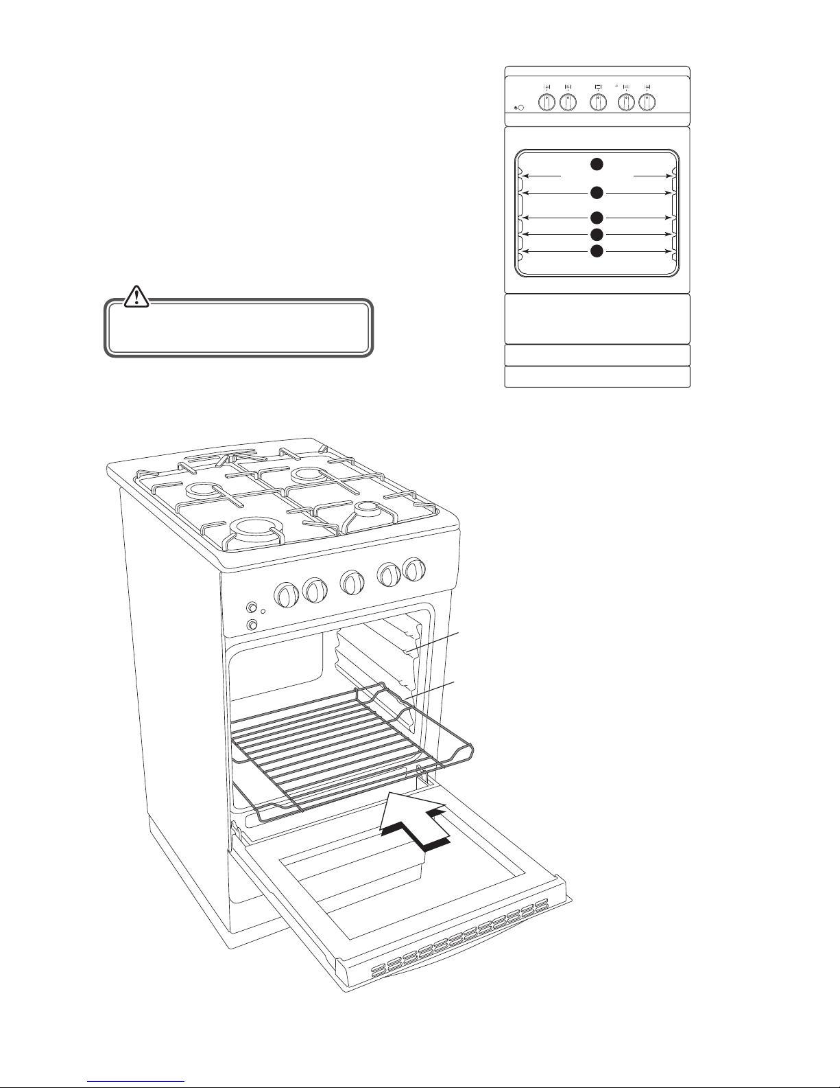
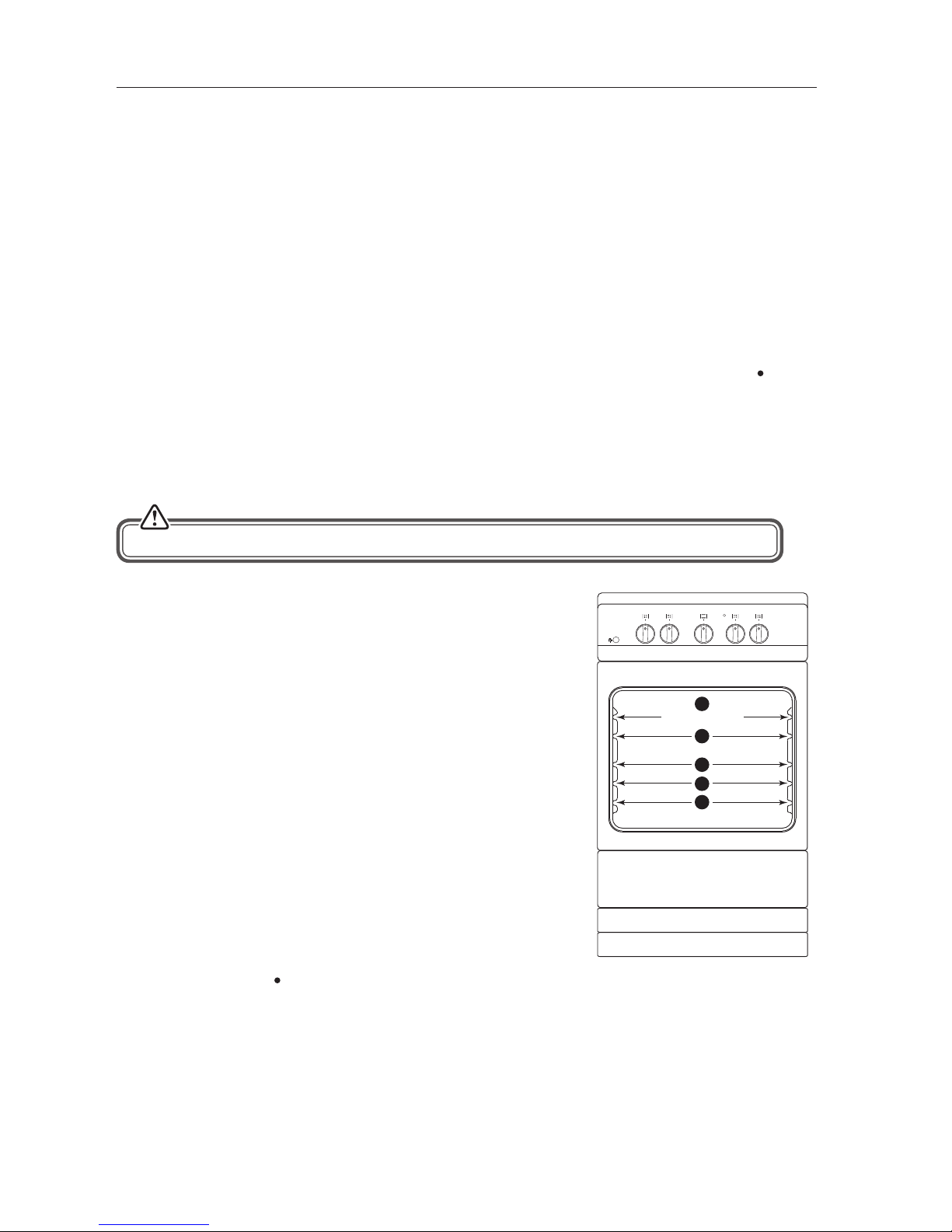
1. On the wall of the inner cavity there are 5 dierent
shelf guide slots. You can place the shelf at dierent
heights to achieve the best cooking performance
depending on the temperature setting and the size
of food. Position 5 is the highest grill position.
2. Always monitor the food during operation to
ensure that you are not overcooking it.
3. For heavy food, use a baking pan rather than the
oven shelf.
• Insert the shelf with the back stop
to the back as shown. Make sure
it is pointing upwards. This will
prevent dishes falling o the back
of the shelf.
• You will notice that about half
way along each shelf, it has a
curve on each side. This is the rest
position of the shelf when pulling
the shelf out of the oven. It will
rest in the recess on the oven side
wall. This prevents the shelf from
tilting forward when removing
cooking pots and trays.
Accessible parts may become hot during
use. Young children should be kept away.
Rest point
recess
Rest point
Grill position
1
2
3
4
5
Page 14
14
Adjusting the Temperature
After you ignite the oven burner as explained before, you can adjust the temperature inside the oven as you
require, using the numbers on the control: Larger numbers mean higher temperatures, while smaller numbers
mean lower temperatures. Refer to the temperature table on the “Cooking” section for the approximate
temperature references of those numbers. Do not operate the appliance between the OFF “ ” position and the rst
temperature marker in the counter-clockwise direction. Always use the oven between the maximum and
the minimum numbers.
The temperature at the centre of the oven corresponds with the selected gas mark and is slightly higher towards
the top of the oven and slightly lower towards the bottom of the oven.
Preheating
When you need to preheat the oven, we recommend you do so for 10 minutes. For recipes needing high
temperatures, e.g. bread, pastries, scones, soués etc., best results are achieved if the oven is preheated rst.
For best results when cooking frozen or cooked chilled ready meals always preheat the oven rst, unless the
cooking instructions advise you otherwise.
Cooking
• Ensure that food is placed centrally on the shelf and that there is sucient room around the baking tray/dish to
allow for maximum heat circulation.
• Stand dishes on a suitably sized baking tray on the shelf to prevent spillage onto the oven base and to help
reduce cleaning.
• The material and nish of the baking tray and dishes used aect browning of the bottom of the food. Enamelware, dark, heavy or non-stick utensils increase browning of the bottom of the food. Shiny aluminium or
polished steel trays reect the heat away and give less browning of the bottom of the food.
• When cooking more than one dish in the oven, place dishes centrally on dierent shelves rather than cluster
several dishes on one shelf, this will allow the heat to circulate freely for the best cooking results.
• If you are cooking more than one tray of similar items, for example cakes or biscuits, swap the trays during
cooking or you can remove the top tray when the food is cooked and move the lower tray to the higher shelf to
nish cooking.
• The thermostat settings detailed below are a guide only and refer to the approximate temperature in the centre
of the oven.
Oven setting 1 2 3 4 5 6 7 8 9 10
Temperature in °C 136 137 154 165 174 185 190 203 215 237
• If accurate temperatures are required then this should be checked using an oven thermometer available at
most cookware shops.
• Do not place baking trays or any covering for example aluminium foil directly on the oven base. It interferes
with the oven air circulation and can lead to burning of the food, or damage the oven cavity. Use the lower shelf
position.
• During cooking, do not open the door unnecessarily as you will lose heat and your cooking results may change.
Cooking times will be longer and energy use will be higher.
• Using cake tins when cooking cakes will give better results.
• During use, the outer and inner surfaces of the oven get hot. While opening the oven door,
step back to avoid the hot steam coming out of the oven. There may be a risk of burns.
• Always use oven gloves to remove and replace food in the oven.
Page 15
15
Cooking with the Grill
First Time Use
Before using the grill for the rst time, heat the grill on maximum for 15 ~ 20 minutes. Ensure that the room is well
ventilated as there may be a little smoke and odour upon initial start up (for about 10 mins). This is normal. It is
due to the protective substance on the element which protects the cooker from the eects of corrosion during
shipping from the factory.
Switching the Grill On
When using the grill the oven door should be closed.
1. Turn the oven dial clockwise to the grill position. Keep the oven door closed while the grill heats up.
2. You can cook your food using any of the shelf positions but obviously position 5 will give the most intense
heat.
3. When turning the grill o, turn the oven dial counter-clockwise direction so that the control shows “
”
position (o) in line with the marking on the control panel.
1. Turn the oven dial clockwise to the grill position. Keep the
oven door closed while the grill heats up.
2. Preheat the grill for a few minutes before sealing steaks or
toasting. The food should be turned over during cooking as
required.
3. Place an oven shelf at your desired height. Ensure there is a
minimum of 30 mm between the food and the grill element, if
not use the lower slot.
4. Using the handle, insert the grill tray and rack onto the oven
shelf. The food to be cooked must be placed on the grill rack.
The handle must be removed once the grill rack tray is
in position and the oven door should be closed– if the
handle is left in position when grilling, it will get very hot.
Check the food regularly to ensure you do not overcook it.
5. The grill pan has a detachable handle. Ensure when using
the grill pan handle that it is centralised and secure as shown
below.
6. At the end of grilling, as in all other cooking processes; turn
the oven dial to the “
” position (o ). Take the grill pan out
by using the supplied handle and put the pan onto a safe
place. Keep children away from the hot oven during and
after grilling, until it has completely cooled down.
Cooking
When using the grill the oven door should be closed.
CAUTION: Accessible parts may be hot when the grill is in use. Young children should be kept away.
Grill position
1
2
3
4
5
Page 16
16
* All images are for indication only; please refer to your individual unit for actual item.
• Never cover the grill pan or grill rack with foil as this can lead to grill res.
• Bread may catch re if the toasting time is too long. Close supervision is
necessary during toasting.
• The handle must be removed once the grill pan is inserted into the oven.
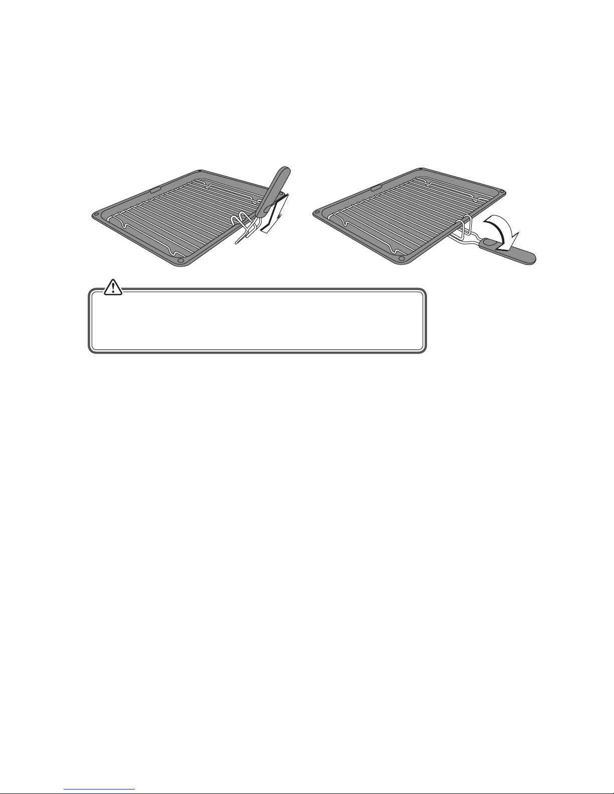
Attaching the Grill Pan Handle
The grill pan handle must be used when you slide the grill pan in and out of the oven.
1. Locate the recess on either side of the grill pan.
2. Tilt the pan handle up and slid over the recess.
3. Let the pan handle fold down until its horizontal with the grill pan. The handle is now attached.
4. To remove the handle once the grill pan is under the grill, tilt the handle upwards and slide it o the grill pan.
Page 17
17
Cleaning Instructions
• Wipe the oven clean after every use.
• Wipe up spills. Avoid leaving alkaline or acidic substances (such as lemon juice or vinegar) on the oven surfaces.
• Do not use cleaning products with a chlorine or acidic base.
• Never clean the interior part, panel, lid, trays and all other parts of the oven with tools like a hard brush,
cleaning mesh or knife. Do not use abrasive, scratching agents and detergents.
• After cleaning the interior parts of the oven with a soapy cloth, rinse it and then dry thoroughly with a soft cloth.
• Never use ammable agents like acid, thinner and gasoline when cleaning your oven.
• Do not wash any part of your oven in a dishwasher.
Cleaning the Outside of the Cooker
Wipe the outside surfaces often, using warm water and a mild household detergent. Any stainless steel parts may
also be cleaned with a suitable cleaner.
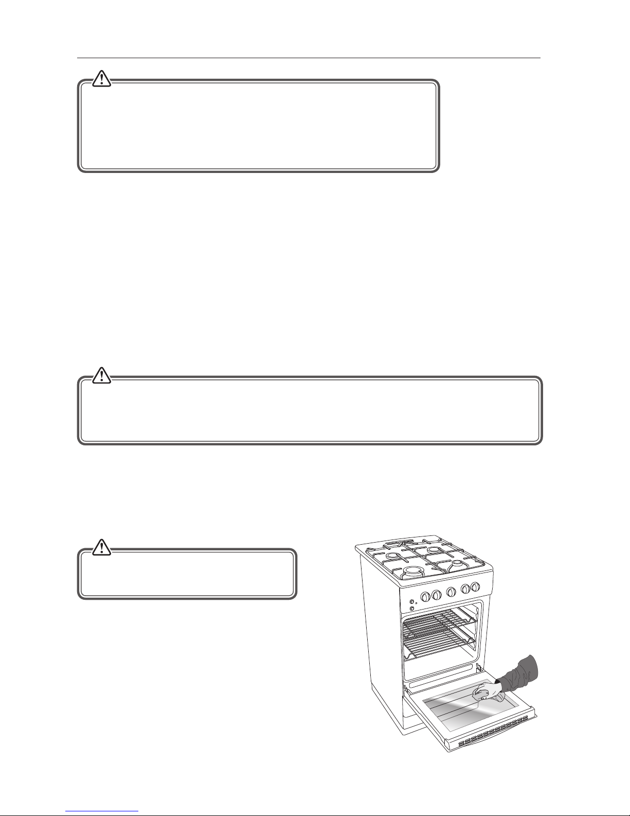
Cleaning the Oven Door Glass
Do not use harsh abrasive cleaners or sharp metal scrapers to clean the oven door since they may scratch the
surface, which could result in the glass shattering.
Before you start cleaning your cooker, please:
• Read the cleaning instructions and the ‘Safety Warnings’ sections.
• Turn the cooker o at the mains socket and disconnect the plug from the socket.
• Allow the cooker to completely cool down before cleaning.
• Do not use a steam cleaner.
• Do not keep ammable substances in, on or near the cooker.
• If you choose to use a commercial stainless steel cleaner, please read the label to make sure it does not
contain chlorine compounds as these are corrosive and may damage the appearance of your cooker.
• Do not use abrasive cleaners, cloths or pads on the outside surfaces.
• Immediately wipe o any caustic cleaners if they are spilled onto the oven door handles.
Take care when handling parts with glass,
knocks, and chips; heavy handling and
dropping could cause the glass to shatter.
* All images are for indication only; please refer to your individual unit for actual item.
Page 18
18
Cleaning the Inside of Your Oven
• Do not use abrasive cleaners, cloths or pads to clean the enamel.
• Clean the enamel on the inside of the oven when it has cooled down, using household detergents or an
ammonia-based cleaner. You may use an ‘o the shelf’ oven cleaner, if you carefully follow the
manufacturers’ instructions.
• The oven door can be removed to allow easier access to the inside of your oven. (See "Removing the Oven
Door" section)
• Wipe the cooker after every use with a soft cloth that has been dampened in soapy water. Wipe it again with
a wet cloth and then dry it. Do not clean with dry or powder cleansers.
• Do not clean the cooker while the glass panels are hot.
• Clean the cooker with a glass cleaner which is designed to be used with cookers. Then rinse and then dry it with
a dry cloth.
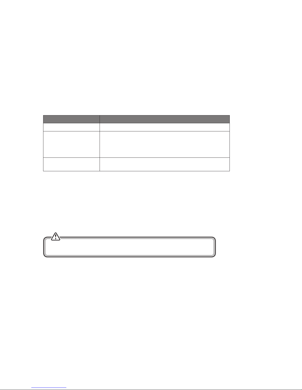
Cleaning the Gas Hob
Maintenance Period Description
Daily • Clean the gas hobs as per the cleaning instructions.
Monthly • Remove all burner parts, and clean using a non-abrasive
detergent. Rinse in cold water, dry thoroughly, and replace.
• Clean the ignitor and probe carefully, using a nylon brush
such as a toothbrush.
Every year • Contact your local authorized gas Service Agent to perform
a thorough check on all gas components on the gas cooker.
Hob Burner Parts and Pan Supports
• You can remove and clean these parts with hot soapy water or non-abrasive detergents. Clean spills regularly
before they become burnt on. Do not wash these parts in a dishwasher.
• After cleaning, check that the burner ring and burner caps are dry before replacing correctly.
• It is very important to check that the burner ring and burner caps have been correctly positioned. Failure to do
so can cause serious problems.
To avoid damage to the electric ignition NEVER light the hob when the burners
are not in place.
Page 19
19
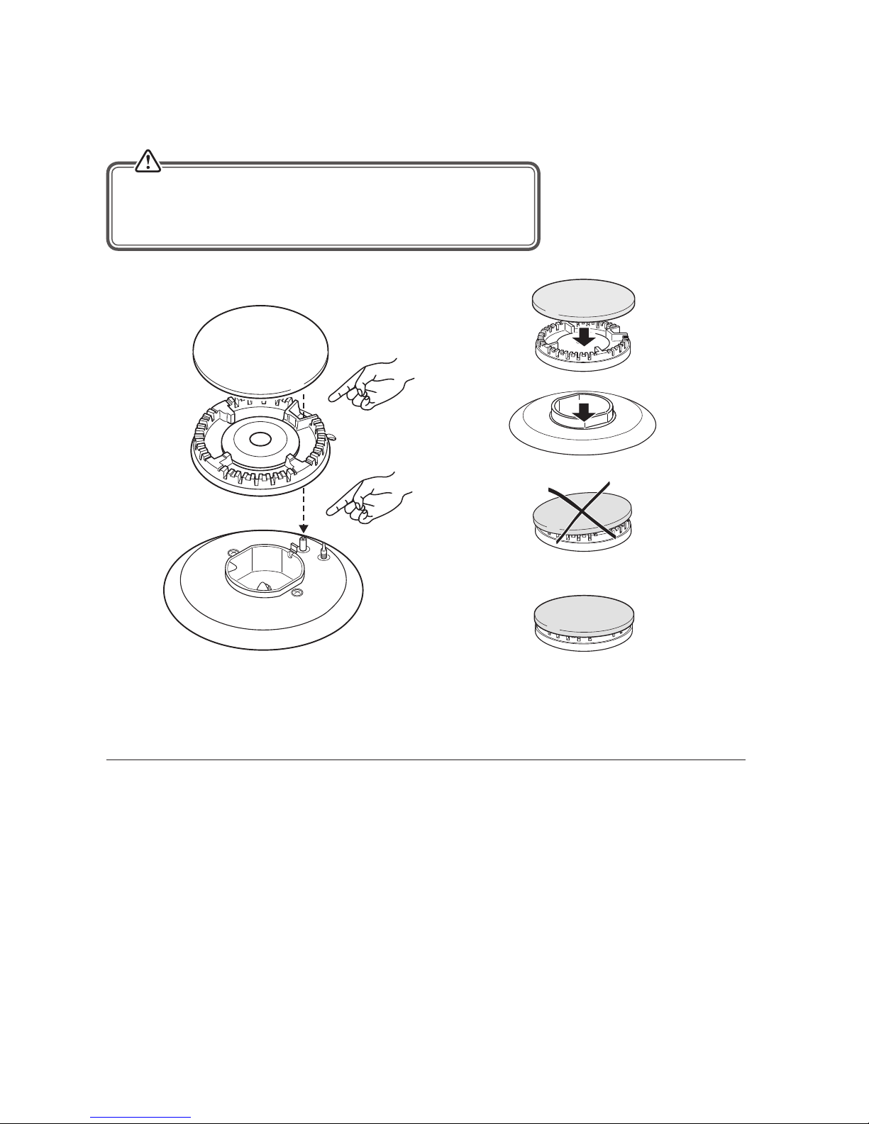
Replacing the Hob Burner Parts
Check that:
• The ignitor is always clean to ensure trouble-free sparking.
• The probe is always clean to ensure correct operation of the safety valves.
Burner Parts Replacing the burner parts
Hob Controls (Gas Taps)
If you have problems with the gas taps, call your Authorised Service Centre.
These parts are NOT user serviceable.
Both the ignitor and probe must be very carefully cleaned using
a toothbrush. When replacing the burner parts, ensure you do not
damage the ignitor or temperature probes.
* All images are for indication only; please refer to your individual unit for actual item.
Page 20
20
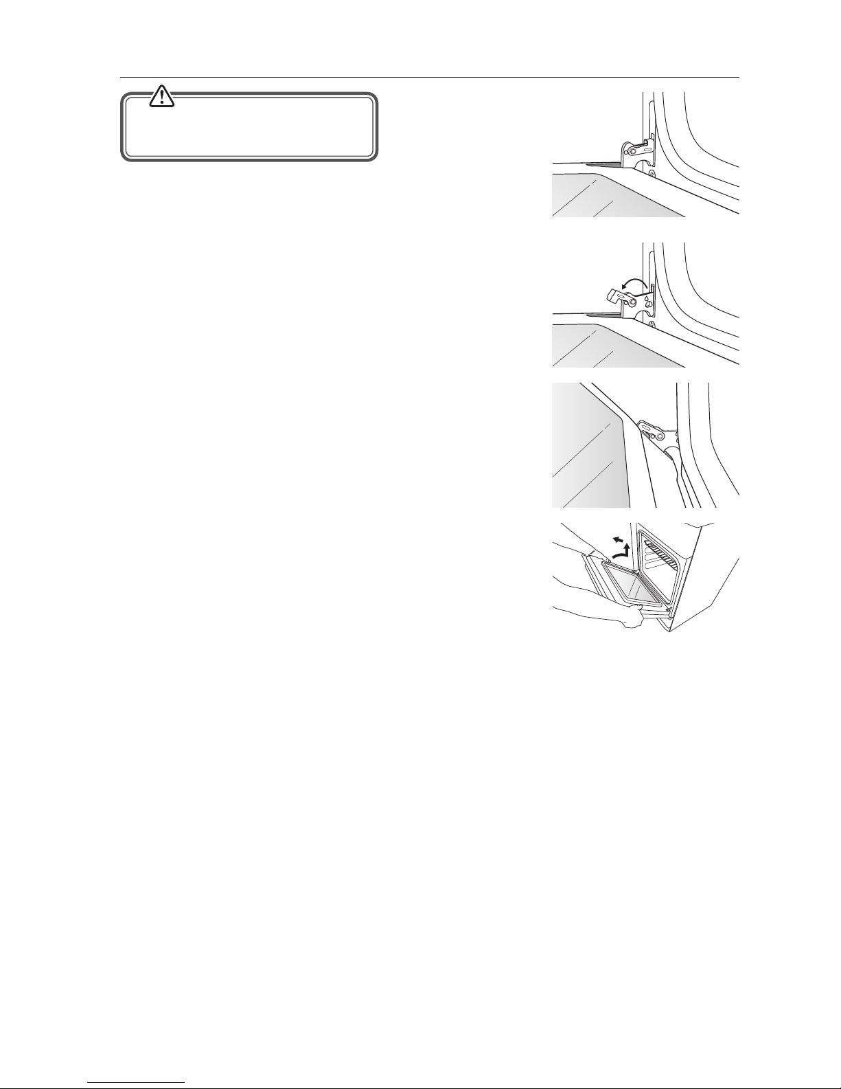
Removing the Oven Door
• Ensure the door has cooled down.
• Take care when handling glass.
The oven door can easily be removed as follows:
1. Open the top oven door completely.
2. The swivel retainers of the right hand and left hand hinges are
hooked onto the metal bar above them. Lift the retainers as shown.
3. Lift the oven door slightly. The notch on the bottom of the hinge will
disengage.
4. Now pull the oven door forwards o the appliance. Releasing both
hinge sections from the slots.
To replace the door, repeat the above steps in reverse order.
* All images are for indication only; please refer to your individual unit for actual item.
Page 21
21
x2
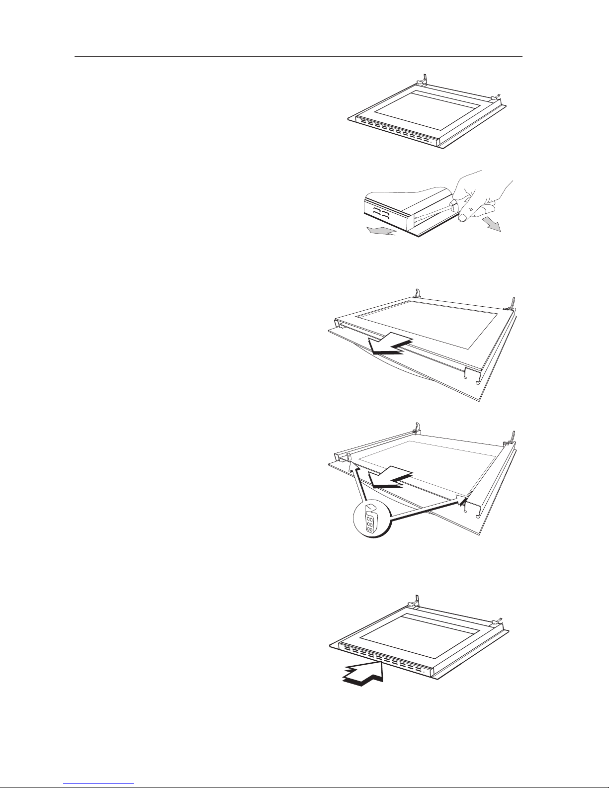
Removing the Oven Glass
1. To remove the glass the door must be removed from
the oven.
2. Using a at head screwdriver and gently prise the
plastic vent o the door. You will need to do this on
both sides.
3. Once the plastic vent is removed the two glass panels
will slide out.
4. When replacing the glass, slide the clear glass panel
in rst. Make sure the rubber spacer is positioned
towards the top of the door as shown. Make sure the
top panel of glass is replaced the correct way around,
with the logos and text facing inside the oven. Line it
up with the metal door frame.
5. Replace the plastic vent, make sure it snaps into place.
Then re-t the door.
Page 22
22
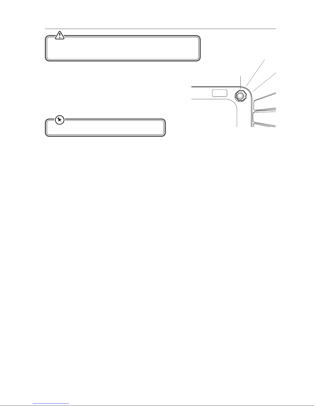
Replacing the Oven Lamp
Oven Lamp
Bulb specications: 230V~ 50 Hz, 25W, E14
1. Let the oven cavity cool down.
2. Remove the protective cover.
3. Unscrew and replace the bulb with a new one suitable
for high temperatures (300°C).
4. Ret the protective cover.
Ensure that the cooker is switched o at the mains before replacing
the lamp to avoid the possibility of an electric shock.
Page 23
23
Installation
* All images are for indication only; please refer to your individual unit for actual item.
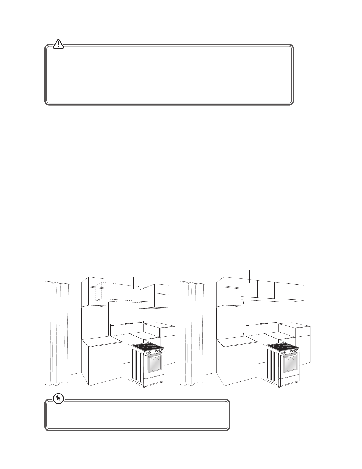
For all dimensions marked “X”, please refer to the information below:
X : 100mm for combustible materials
20mm for non-combustible materials.
This appliance must be installed and serviced only by a suitably qualied and Gas Safe Registered
engineer, and in accordance with the current editions of the following standards and regulations
or other locally applicable regulations:
• Gas Safety (Installation and Use) Regulations
• Building Regulations
• British Standards (BS 5440, BS 6172 and BS 6891)
• Regulations for Electrical Installation (BS 7671, (Latest Edition))
• If the cooker is installed adjacent to furniture which is higher than the gas hob, a gap of at least 100 mm must
be left between the side of the cooker and the furniture unless non-combustible materials (ceramic tiles,
metal splashback etc.) are used which then allows this distance to be reduced to 20 mm.
• Prior to installation, ensure that the local distribution conditions (nature of the gas and gas pressure) and the
adjustment of the appliance are compatible. The adjustment conditions for this appliance are stated on the
label (or data plate).
• This cooker must be tted with a stability bracket.
• The furniture walls adjacent to the cooker must be made of heat resistant material (check with your furniture
supplier). The veneered synthetic material and the glue used must be resistant to a temperature of 100°C in
order to avoid ungluing or deformations.
• Flammable materials such as curtains, wood, wallpaper etc. must not be tted immediately behind the
appliance or within 500 mm of the sides.
• Do not place next to a refrigerator.
• This cooker must NOT be placed on a pedestal or base.
• It is essential that the cooker is positioned as stated or freestanding ensuring the distances to ammable
materials etc. are still observed.
• Any cooker hoods must be installed according to the requirements of the cooker hood instruction/installation
manual but no less than 650 mm.
• Any cupboards placed directly above the cooker must be no less than 700 mm.
600 mm
420 mm
700 mm
X
Cupboard
600 mm
420 mm
650 mm
X
Cupboard
Cooker Hood
Page 24
24
* All images are for indication only; please refer to your individual unit for actual item.
Ventilation Requirements
This appliance is not connected to a combustion products evacuation device. It should be installed and
connected in accordance with current installation regulations. Particular attention should be given to the relevant
requirements regarding ventilation.
The appliance should be installed in a room or space with an air supply in accordance with the latest edition
of BS5440-2. This appliance needs 2 m
3
/h air per Kw input
For rooms with a volume of less than 5 m
3
— permanent ventilation of 100 cm2 free area will be required.
For rooms with a volume of between 5m
3
and 10m3 a permanent ventilation of 50 cm2 free area will be required
unless the room has a door which opens directly to the outside air in which case no permanent ventilation
is required.
For rooms with a volume greater than 10 m
3
— no permanent ventilation is required.
Adjusting the Feet
Using the tted adjustable feet is MANDATORY. For safety reasons and to ensure adequate
ventilation, the cooker chassis MUST NOT sit directly on the oor, a plinth, or other support surface.
• Regardless of room size, all rooms containing the appliance must have direct access to the outside
air via a window that opens or equivalent.
• Where there are other fuel burning appliances in the same room, the latest edition of BS 5440-2
should be consulted to determine the correct amount of free area ventilation requirements.
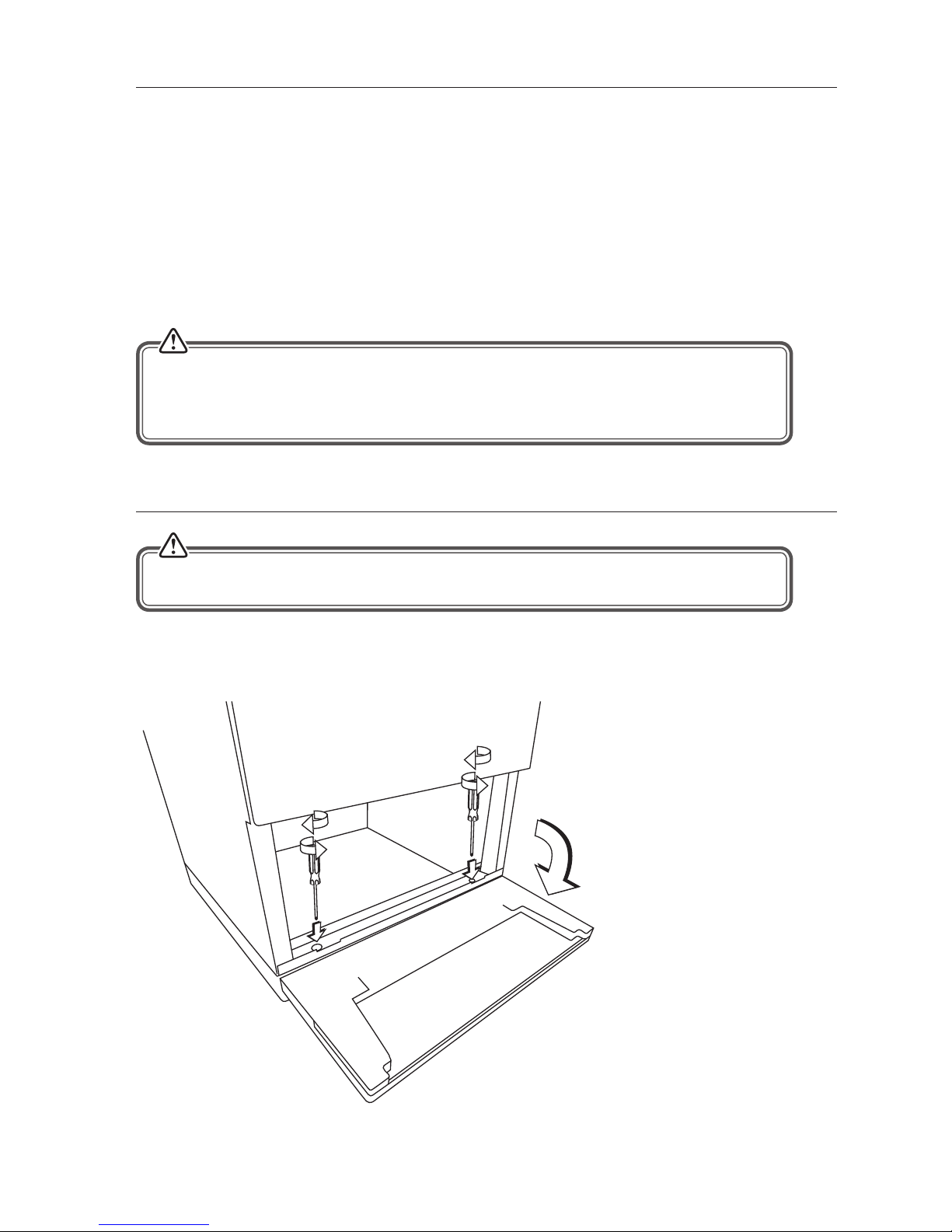
Your appliance must be level before use. The cooker has 4 levelling feet which can be adjusted. It is possible
to adjust the level by a maximum of 15 mm via the levelling feet.
1. Open the front ap to access
the adjustable feet.
2. Your cooker has 4 adjustable
feet, 2 at the front and 2 at
the rear of the cooker.
3. Use a at head screwdriver to
adjust the feet.
Turn clockwise to raise the
cooker.
Turn anti-clockwise to lower
the cooker.
4. Close the ap once level.
Page 25
25
* All images are for indication only; please refer to your individual unit for actual item.
Moving the Cooker
• Two people must always raise the cooker, as shown,
to prevent damaging the adjustable feet.
• Do not lift the cooker by the door handles.
• DO NOT DRAG the cooker. Lift the feet clear of the oor.
The product must NOT be moved by dragging. The cooker must
always be moved by lifting it up.
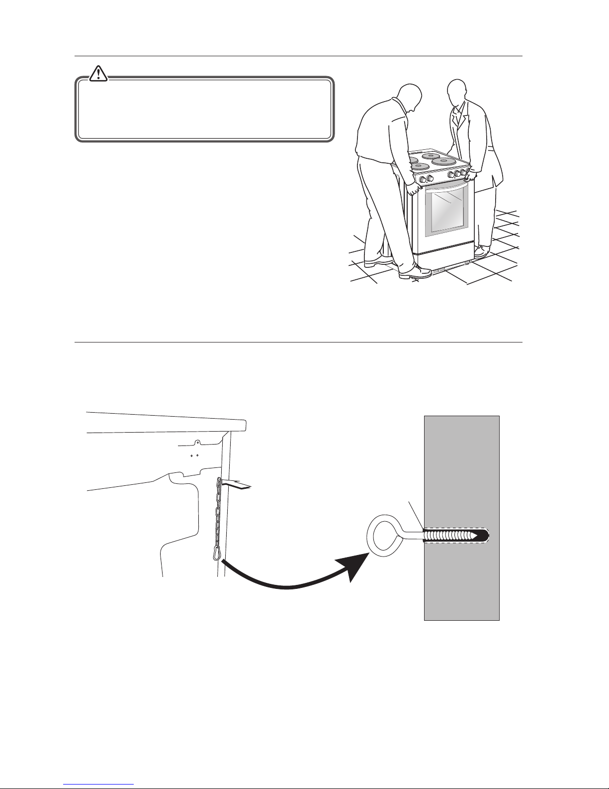
Stability Device
The supplied stability device or a recognized cooker stability device must be tted to the back of the cooker as
shown.
Wall Plug
1. Adjust the feet to make sure the appliance is level before tting the stability device.
2. Screw the chain to the back of the cooker as shown above.
3. Screw the eyelet into the wall at a height of 750mm from the oor level.
4. Clip the chain onto the eyelet.
Page 26
26
Gas Connection
• Only a suitably qualied and Gas Safe Registered Engineer may convert the appliance to
a dierent gas type.
• This cooker uses and is ready to use NATURAL GAS only and cannot be used with any other gas
without modication. This appliance is manufactured for conversion to LPG after tting new injectors
(supplied) and making adjustments. Refer to “replacement of burner injectors” section for details.
• When using Butane (G30) gas a supply pressure of 28 -30 mbar is required.
• When using Propane (G31) gas a supply pressure of 37 mbar is required.
• Flexible hoses must be manufactured in accordance with relevent standards and regulations in
force, and be suitable for gas type being used.
• The hose should not be crushed or trapped or be in contact with sharp or abrasive edges.
It should also not be subjected to corrosion by acidic cleansing agents.
Do not use a naked ame to test for leaks.
* All images are for indication only; please refer to your individual unit for actual item.
The installation of the cooker to Natural Gas or LP Gas (using the LPG conversion kit supplied) must be carried out
by a Gas Safe registered engineer. Installers must take account of the provisions of the relevant British Standards
Code of Practice, the Gas Safety Regulations and the Building Regulations.
Installation for Using Natural Gas
Installation to Natural Gas must conform to the Industry Standards, etc. The supply pressure for Natural Gas is 20 mbar.
Installation for Using Liquid Petroleum Gas (LPG)
This appliance must only be connected to LPG after the supplied LPG conversion kit has been tted.
The installation must conform to the relevant British Standards.
During gas connection and re-connection, a sealing material that is either
• PTFE tape approved to BS EN 751-3;
• Or jointing compound suitable for Natural Gas complying to BS 6956-5 or BS EN 751-1
should be used between connection surfaces.
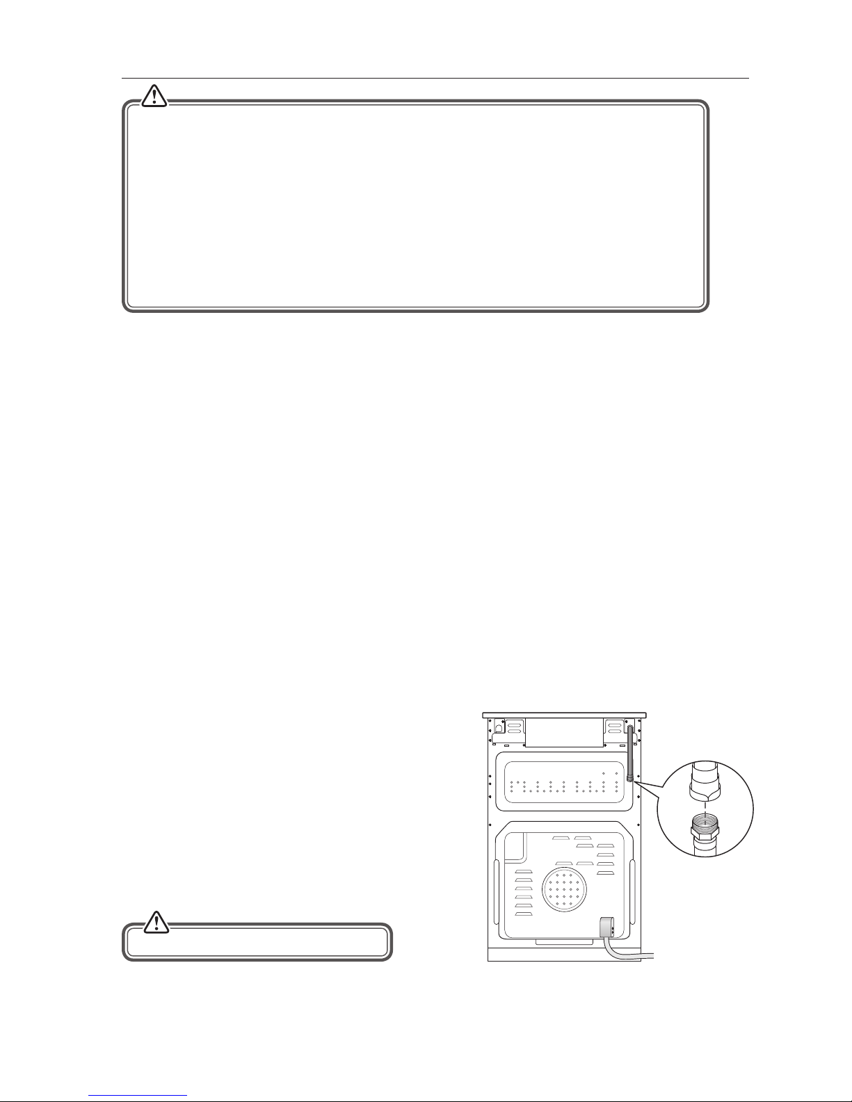
To Connect the Gas Supply
1. Connect the gas supply to the gas inlet at the rear
of the cooker. The gas hose must hang in a “U” shape
behind the cooker.
2. Undertake a full gas tightness test.
3. To avoid damage to the appliance gas rail inlet pipe
tighten the ttings using two suitable spanners.
4. Using a suitable leak detection uid solution check each
gas connection one at a time by brushing the solution
over the connection. The presence of bubbles will
indicate a leak. If there is a leak, tighten the tting and
then recheck for leaks.
Page 27
27
Replacement of Burner Injectors
Injector
Spanner
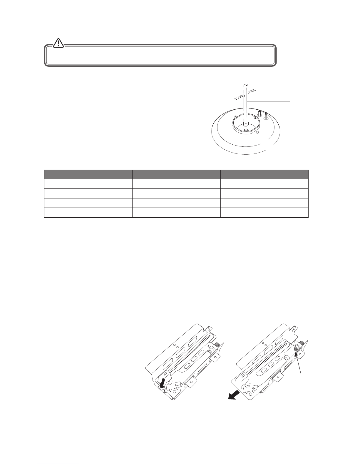
Select the injectors to be replaced according to the “Injector Size Table”.
To Replace the Hob Injectors
• Turn o and isolate the gas and electric supplies to the cooker.
• Remove the burner ring and cap.
• Unscrew the injectors. For this, use a 7 mm socket spanner.
• Replace the injector with the ones from the conversion set,
with the corresponding diameters suitable to the type of gas
that is going to be used, according to the information chart
(which is also supplied in the conversion set).
The gas ow adjustment is made by turning a small screw on the control valves.
From LPG to Natural Gas From Natural Gas to LPG
Large Burner 1 turn counter-clockwise Turn fully clockwise
Standard Burner 3/8 turn counter-clockwise Turn fully clockwise
Small Burner 1/4 turn counter-clockwise Turn fully clockwise
Oven Burner 1/4 turn counter-clockwise Turn fully clockwise
Adjusting the Reduced Flame Position
The ame length in the minimum position is adjusted with a at screw located on the side of the valve spindle
under the hob controls. The screw must be loosened by (see table above) when changing from LPG to NG. In
changing from NG to LPG, the same screw must be fully tightened clockwise. Make sure that the appliance is
disconnected from the mains supply and the gas feed is on.
When the ame has a length of at least 4 mm, the gas is well distributed. Make sure that the ame does not die
out when passing from the maximum position to the minimum position. Create an articial wind with your hand
toward the ame to see if the ames are stable.
To Replace the Oven Injector
The oven burner is located under at the back of the oven cavity.
1. Remove the 2 screws from the ame guard and remove the guard. This will now give you access to the oven
injector.
2. Remove the clips from the ignitor
and FSD.
3. Slide the ignitors and FSD out of
their clap sockets.
4. Press down on the clip then lift up
and slide out the burner manifold.
Only a suitably qualied and Gas Safe Registered Engineer may change the Hob Injectors. It is
illegal to attempt to change the Hob Injectors yourself.
Remove the injector with a 7mm spanner and replace the injector with the ones from the spare set, with
corresponding diameters suitable to the type of gas that is going to be used, according to the information chart
(which is also supplied in the gas conversion kit).
Injector
Page 28
28
* All images are for indication only; please refer to your individual unit for actual item.
Injector Size Table
Burner Injector Values According To The Gas Type.
Destination: GB Gas Category II
2H3+
LPG Natural Gas
G 30/31
28-30/37 mBar
G 20
20 mBar
Large Burner (Fast)
Injector mm 0.83 1.17
Gas Flow (15°C and 1013mbar) 203 gr/h 266 lt/h
Power kW 2.800 2.800
Standard Burner
Injector mm 0.67 0.98
Gas Flow (15°C and 1013mbar) 131 gr/h 171 lt/h
Power kW 1.800 1.800
Small Burner (Simmer)
Injector mm 0.52 0.72
Gas Flow (15°C and 1013mbar) 73 gr/h 95 lt/h
Power kW 1.000 1.000
Main Oven Burner
Injector mm 0.79 1.15
Gas Flow (15°C and 1013mbar) 183 gr/h 238 lt/h
Power kW 2.500 2.500
• All intervention regarding installation maintenance and conversion of the appliance must be fullled with
original factory parts.
• The manufacturer declines any liability if these correct parts are not used.
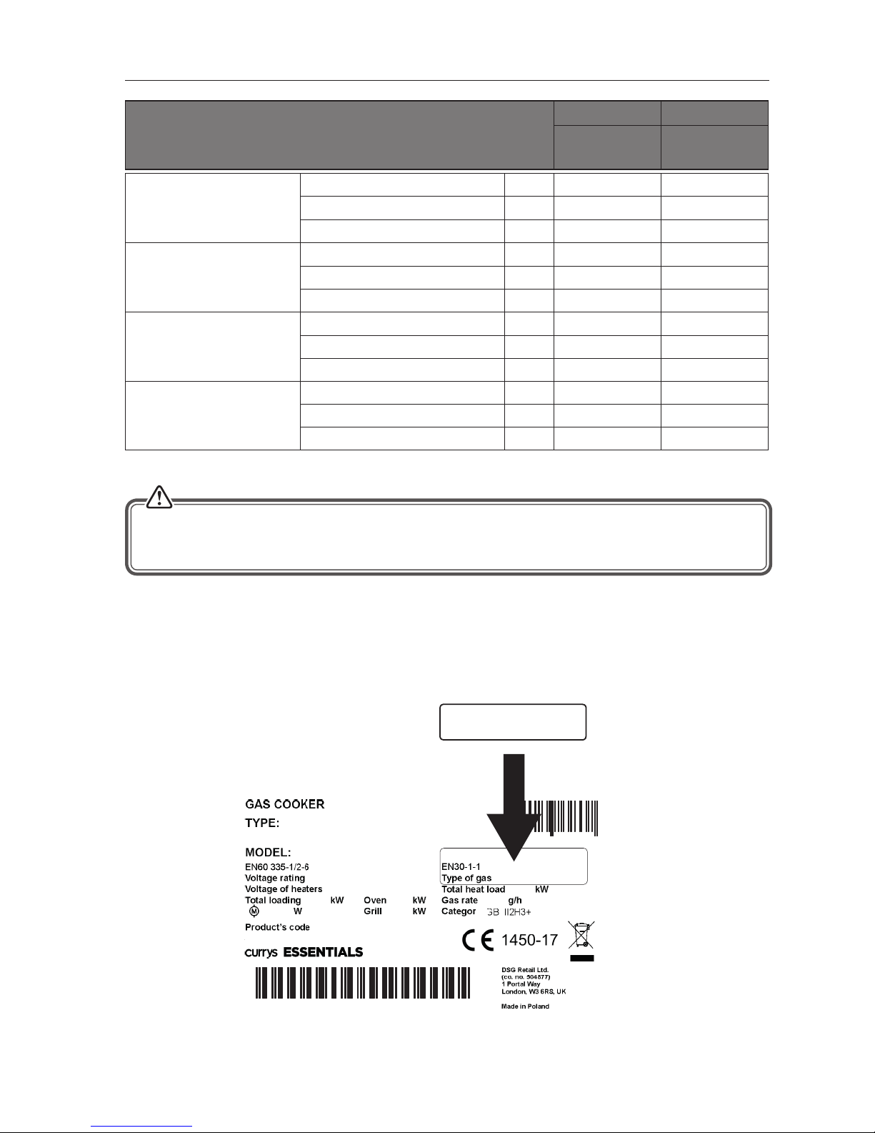
Where to place the LPG Replacement Rating Plate Sticker
If the oven is changed to LPG, the replacement rating plate sticker MUST be placed as shown below.
5 017416 768337
5010GG5.33ZPFGW cf
CFSGWH17
56186
G20-2H-20
mba
r
721
230V~50Hz
2,02,
0
2
,
0
9,9
0
2
3
0
V
88885618688888
S/N
Type of gas
3+ G30/31 28-30/37 mbar
8056867
21
2,5
Page 29
29
Electrical Connection
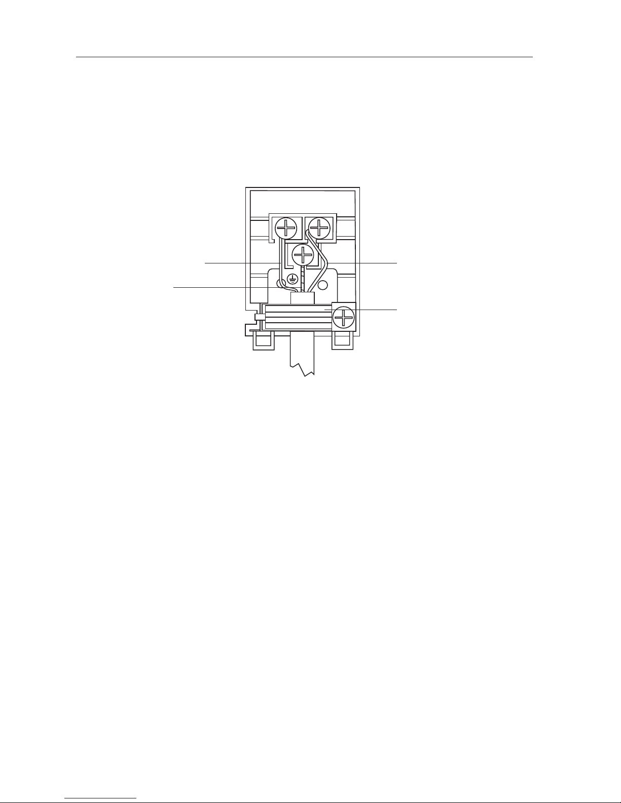
This cooker is tted with a BS1363 moulded plug. The mains plug must remain accessible when the cooker is in its
place of use.
If the installation requires any alterations to the domestic electric system, this must be performed by a qualied
electrician.
The mains cable must be routed away from any hot parts.
If the mains cable is damaged, it must be replaced by the manufacturer, its service agent or similarly qualied
persons in order to avoid a hazard.
L
N
Live (Brown)
Earth
(Green/Yellow)
Neutral (Blue)
Cord Clamp
* All images are for indication only; please refer to your individual unit for actual item.
Page 30

30
Product Fiche and Specications
Brand Essentials
Model CFSGSV17/CFSGWH17
Product Type Gas Cooker
Mass of the appliance 35 Kg
Main Oven
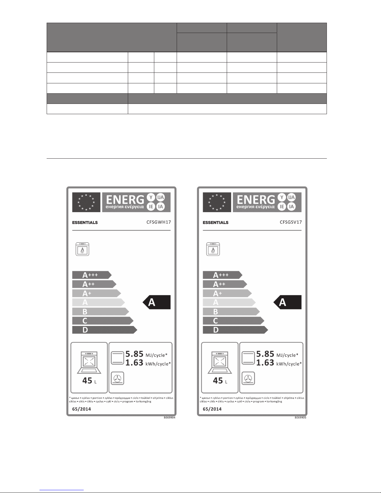
Energy Eciency Index - Conventional 106.2
Energy Class A
Energy Consumption (gas) - Conventional
5.85 MJ/cycle
1.63 kWh/cycle
Number of Cavities 1
Heat Source Gas
Volume 45 litres
This product complies with EN 15181
Overall Dimension (W x D X H)
500(W) x 600(D) x 900(H) mm
(Not including Controls or Handles)
Oven Lamp 25 W E14, 300°C
Supply Voltage 230-240V ~
Rated Frequency 50 Hz
Type of Hob Gas
Number of Cooking Zones 4
Heating Zone(s) Small
Heating Technology Gas
Size 9-15cm
Energy Eciency 54.5%
Heating Zone(s) Medium
Heating Technology Gas
Size 16-22cm
Energy Eciency 54.5%
Heating Zone(s) Large
Heating Technology Gas
Size 20-24cm
Energy Eciency 54.5%
Energy Eciency of Hob 54.5%
This Hob Complies with EN 30-2-1
Features and specications are subject to change without prior notice.
Page 31
31
Burner in Values
According to the Gas Type
LPG Natural Gas
Energy
Eciency
G 30/31
28-30/37 mBar
G 20-20
mBar
Large Burner (Fast) Power kW 2.8 kW 2.8 kW 54.5%
Standard Burner Power kW 1.8 kW 1.8 kW 54.5%
Small Burner (Small) Power kW 1.0 kW 1.0 kW 54.5%
Oven Burner Power kW 2.5 kW 2.5 kW -
Grill Output Power Electric
Grill (ELECTRIC) 2.0kW
Energy Labels
Page 32
CFSGWH17/SV17_170705V2
Visit Partmaster.co.uk today for the easiest way to buy electrical spares and accessories. With over 1 million
spares and accessories available we can deliver direct to your door the very next day.
Visit www.partmaster.co.uk or call 0344 800 3456 (UK customers only). Calls charged at National Rate.
For general information about this appliance
and handy hints and tips, please visit
www.knowhow.com/knowledgebank or call 0344 5611234.
DSG Retail Ltd. (co. no. 504877)
1 Portal Way, London, W3 6RS, UK
The symbol on the product or its packaging indicates that this product must not be disposed
of with your other household waste. Instead, it is your responsibility to dispose of your waste
equipment by handing it over to a designated collection point for the recycling of waste electrical
and electronic equipment. The separate collection and recycling of your waste equipment at the
time of disposal will help conserve natural resources and ensure that it is recycled in a manner that
protects human health and the environment.
For more information about where you can drop o your waste for recycling, please contact your
local authority, or where you purchased your product.
 Loading...