

Page 1
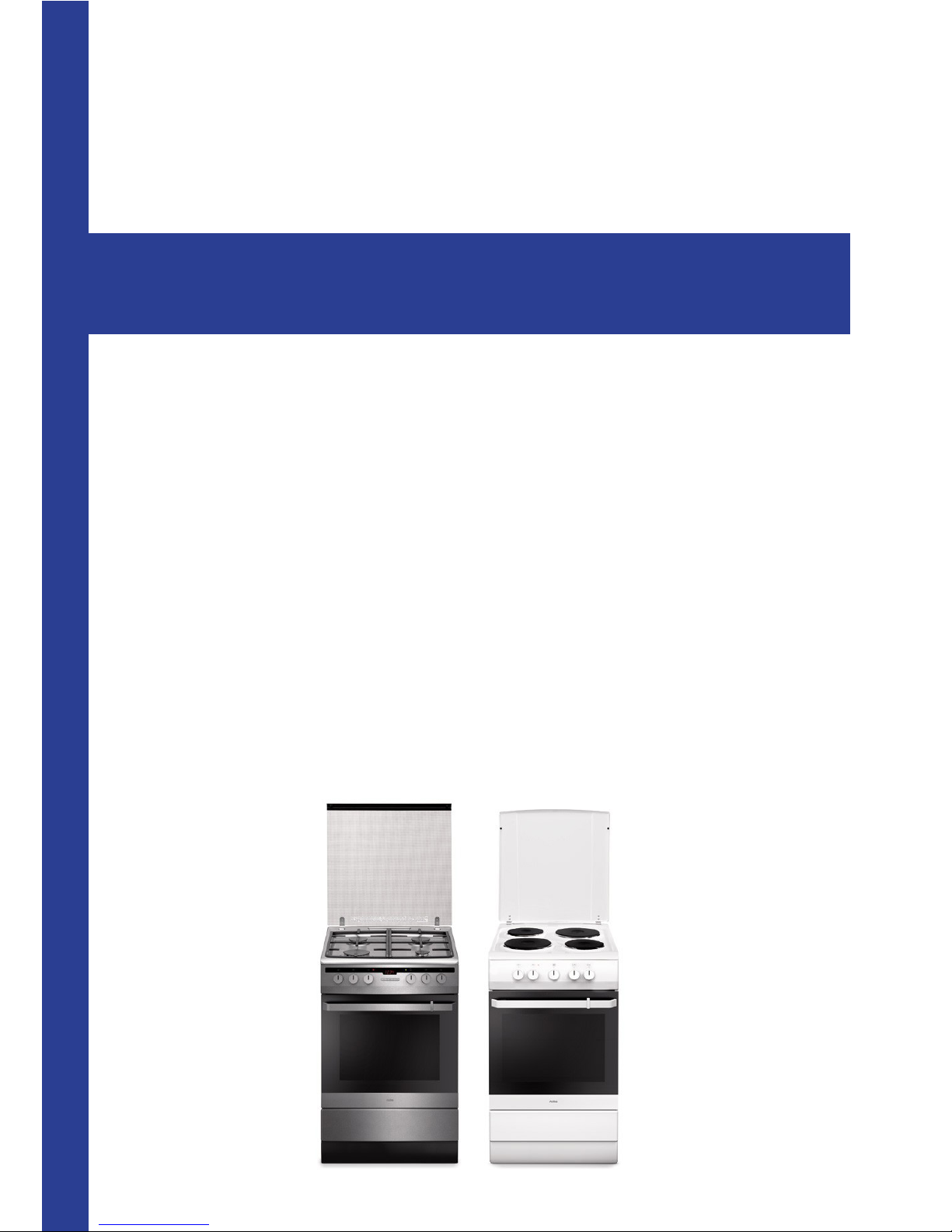
Freestanding cooker 500 and 600 / Range 2013
Gas- gas
Electric
CFSGSV14
CFSGWH14
CFSESV14
CFSEWH14
SERVICE MANUAL
Page 2

2
Page 3
3
Door assembly
Removing the door assembly
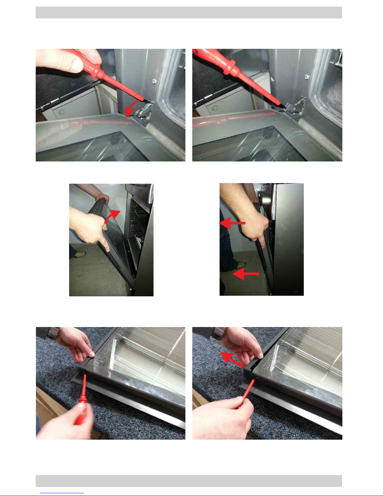
1. Lift the lock of the left and right door hinge.
2. Position the door at an angle of 45° relative to the front of the appliance, lift and
pull out toward yourself.
3. Place the door on a at surface with the handle facing downward. Using a at
screwdriver, pry the cap of the prole on one side to remove it.
Page 4
4
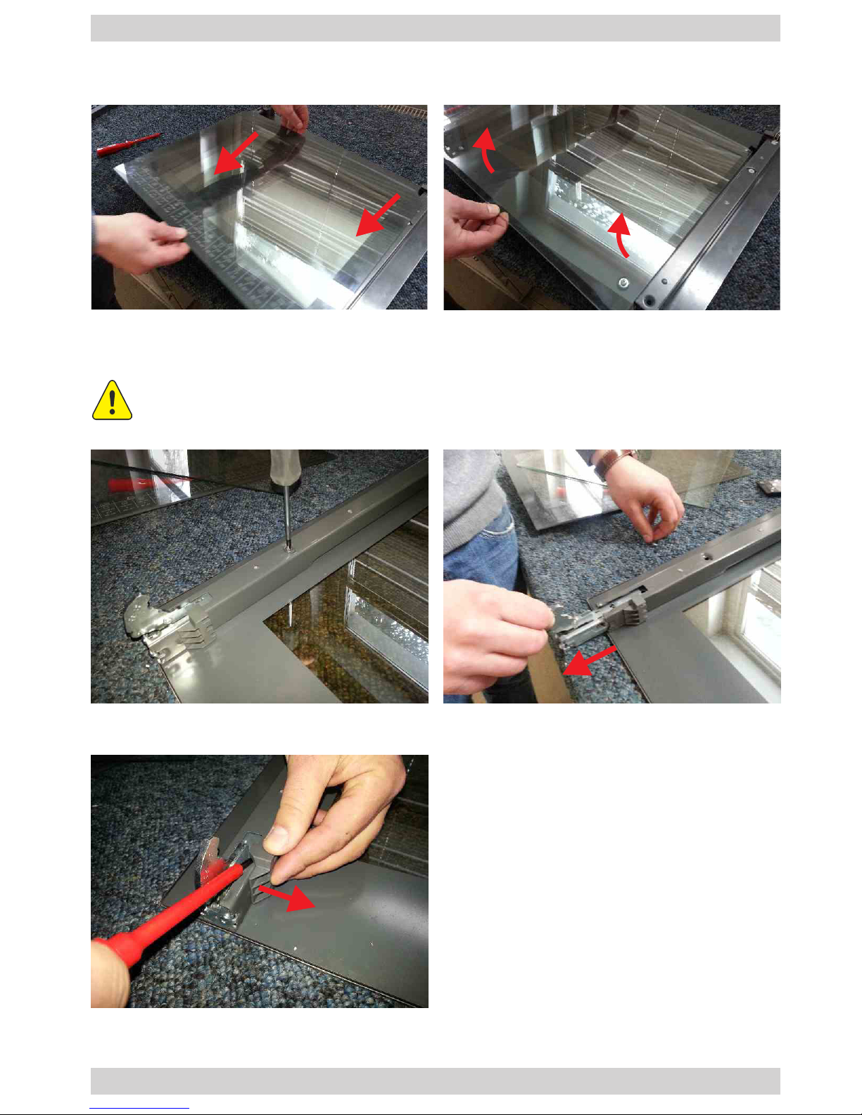
4. Pull out the inner glass panel and carefully lift it. Do the same with the middle
glass panel(s).
Door assembly
5. Remove the screw that fastens the hinge to the inner glass prole. Pull the hinge
out of the prole.
6. Use the screwdriver to pry and remove the glass panel bracket.
Refer to the Annex to the SBI_001 service manual.
Page 5
5
Door assembly
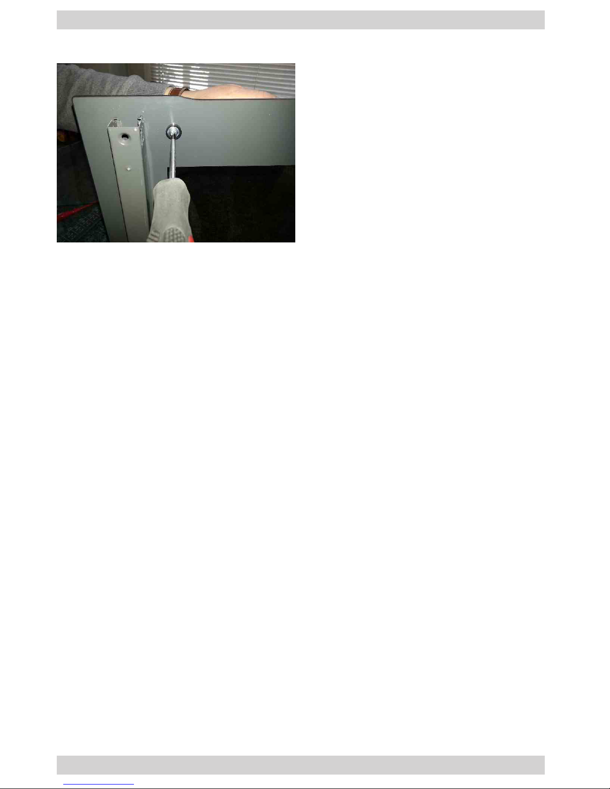
7. Remove the door handle by undoing the screws.
8. To reassemble the components follow the above steps in reverse order.
Page 6
6
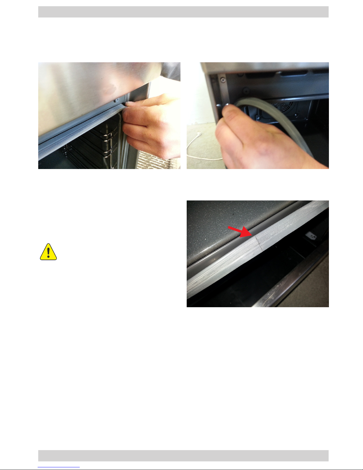
Oven chamber seal
Dismantling the oven chamber seal
1. Unhook the seal holders from the front wall in four places (in the corners).
2. To reassemble the components follow the above steps in reverse order.
The seal should be mounted
with the joint facing down.
Page 7
7
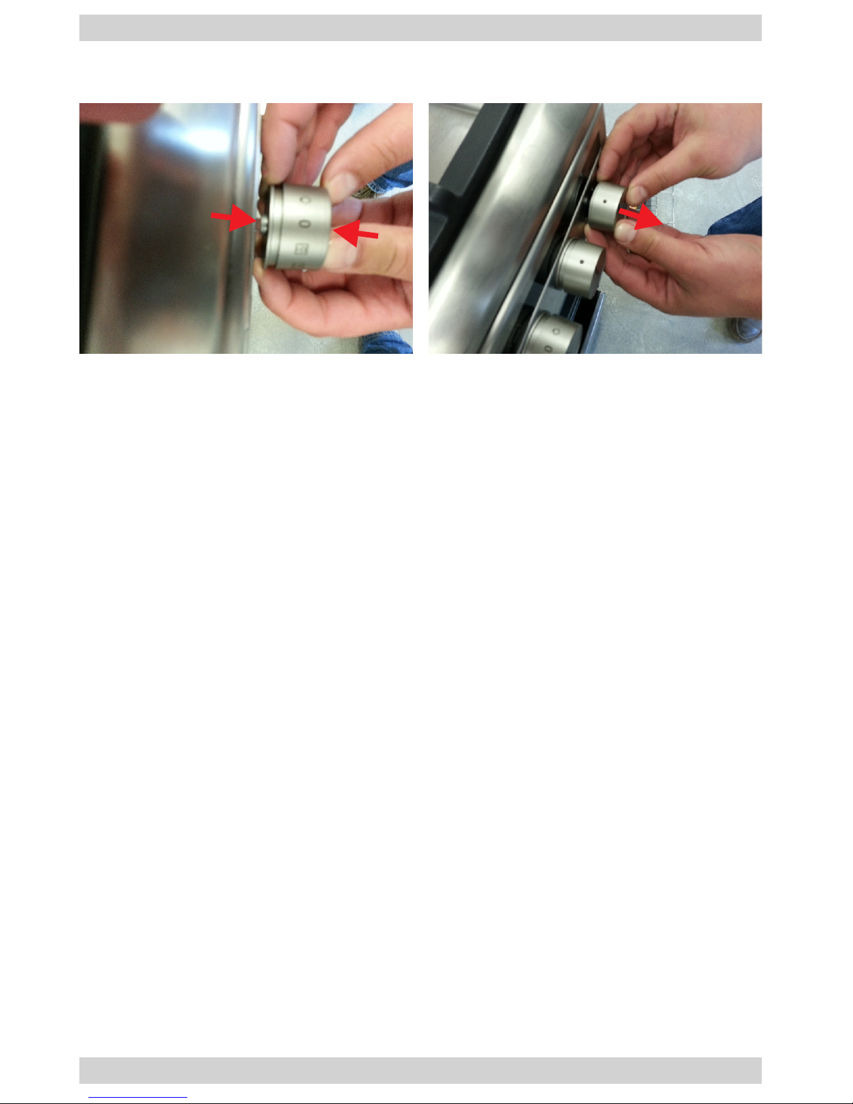
Knob assembly (gas cooker)
1. Pry the knob's interior part, squeeze both parts together and pull toward yourself.
2. To reassemble the components follow the above steps in reverse order. Important! There is a spring between the two elements.
Page 8
8
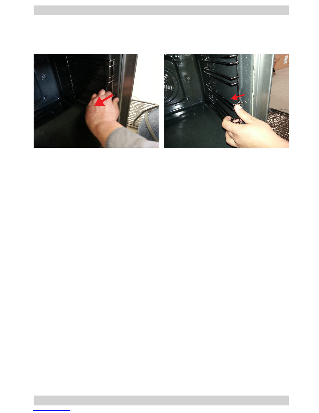
Oven shelves
Dismantling the shelf supports
1. Remove the runners from the shelf supports, unhook the shelf supports from the
mounting holes.
2. To reassemble the components follow the above steps in reverse order.
Page 9
9
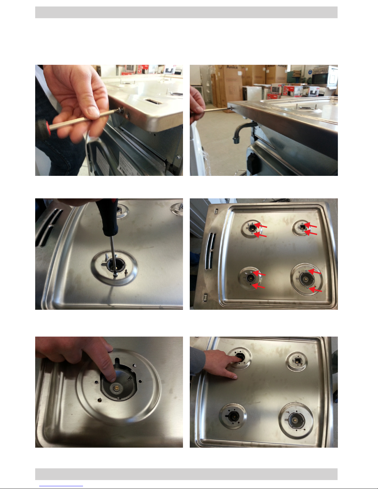
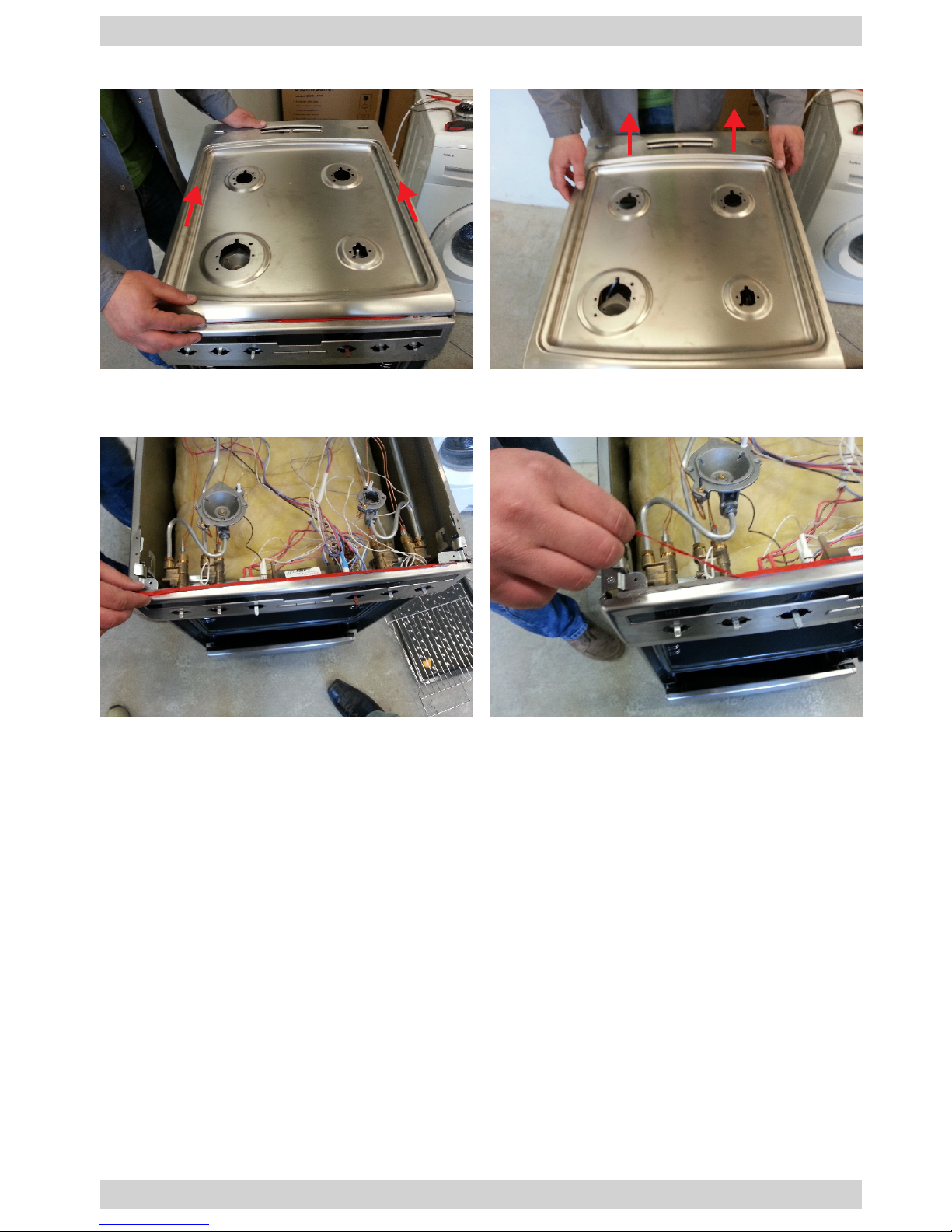
Hob (gas cooker)
1. To dismantle the cover assembly open it maximally (to vertical position) and pull
it upward. Remove the two screws that x the hob to the freestanding cooker
body.
Dismantling the hob
2. Undo the screws that x the burner bodies (two screws for each burner).
3. Gently push the burner body to the inside; pay special attention not to damage
the thermocouple and spark igniter.
Page 10
10
Hob (gas cooker)
4. Gently slide the hob toward the back and lift it.
5. After dismantling the hob, remove the old seal and, after repair, install a new seal
when mounting the hob.
6. To reassemble the components follow the above steps in reverse order.
Page 11
11
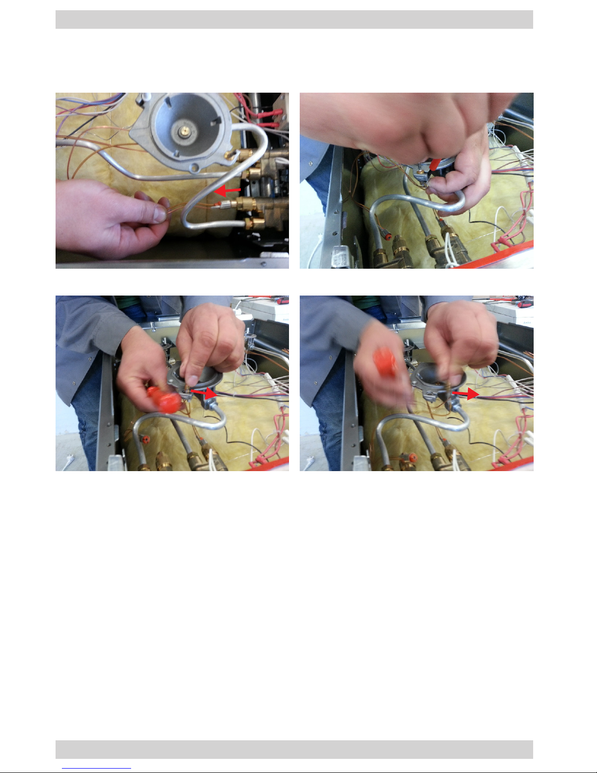
Thermocouple (gas cooker)
1. Unhook the thermocouple from the valve. Unhook the thermocouple lock located
in the burner body, prying it with a at screwdriver.
Replacing the thermocouple
3. To reassemble the components follow the above steps in reverse order.
2. Slide the thermocouple from the burner body guide.
Page 12
12
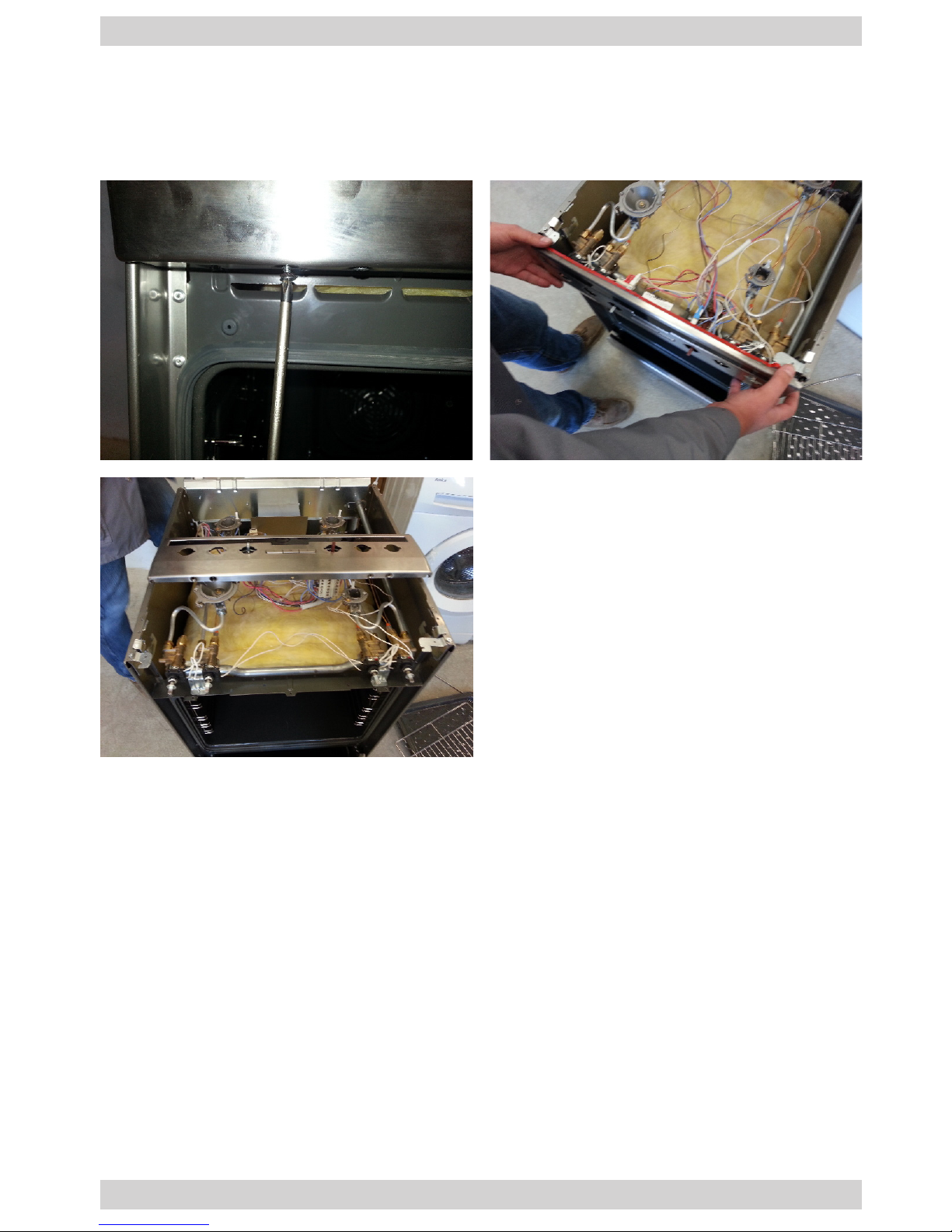
Front panel assembly
1. Dismantle the door assembly. Remove the two screws that x the front panel to
the freestanding cooker body. The screws are located on the bottom of the panel
and are visible after opening or dismounting the door. Gently pull the panel to-
ward yourself.
Dismantling the front panel
2. To reassemble the components follow the above steps in reverse order.
Page 13
13
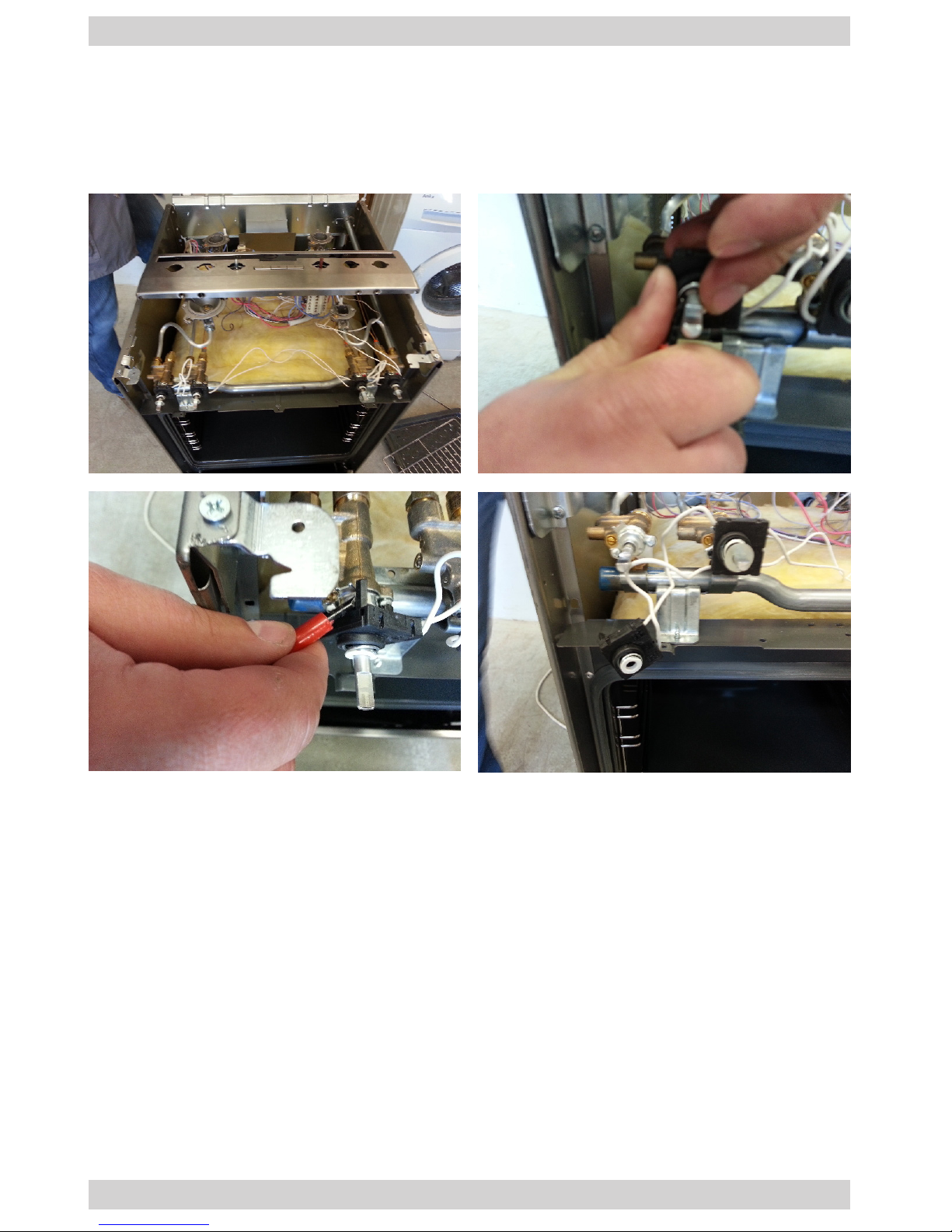
Igniter connector assembly (gas cooker)
1. Dismantle the knobs, dismantle the front panel assembly. Remove the washer
located directly under the knob assembly, on the valve stem. Pry and turn the
igniter assembly and remove it from the valve. Repeat the procedure for all igniter
connectors.
Dismantling the igniter connector
2. To reassemble the components follow the above steps in reverse order.
Page 14
14
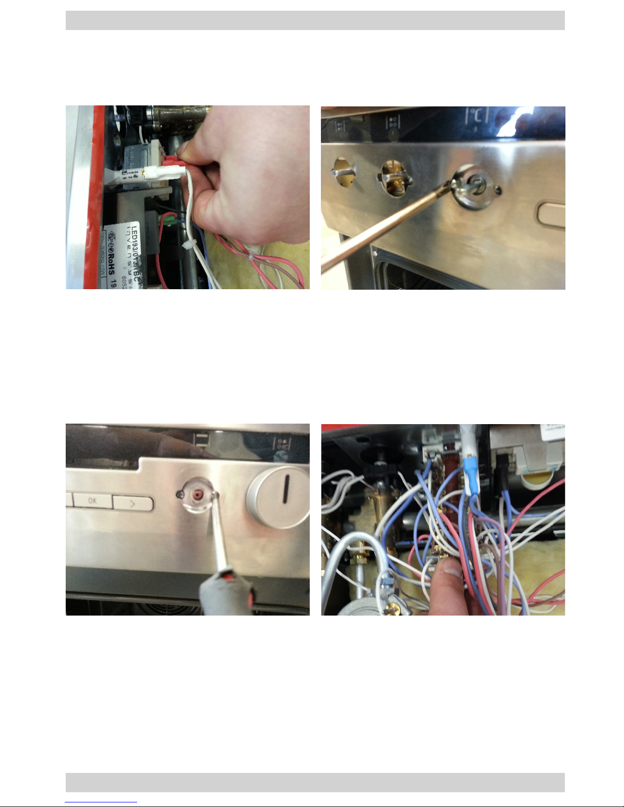
Temperature regulator assembly and function switch
1. Dismantle the hob, dismantle the knob. Disconnect the temperature regulator
wiring harness. Remove the two screws that x the regulator.
Dismantling the temperature regulator
2. To reassemble the components follow the above steps in reverse order.
Dismantling the function switch
1. Dismantle the hob, dismantle the knob. Disconnect the function switch wiring harness. Remove the two screws that x the function switch.
2. To reassemble the components follow the above steps in reverse order.
Page 15
15
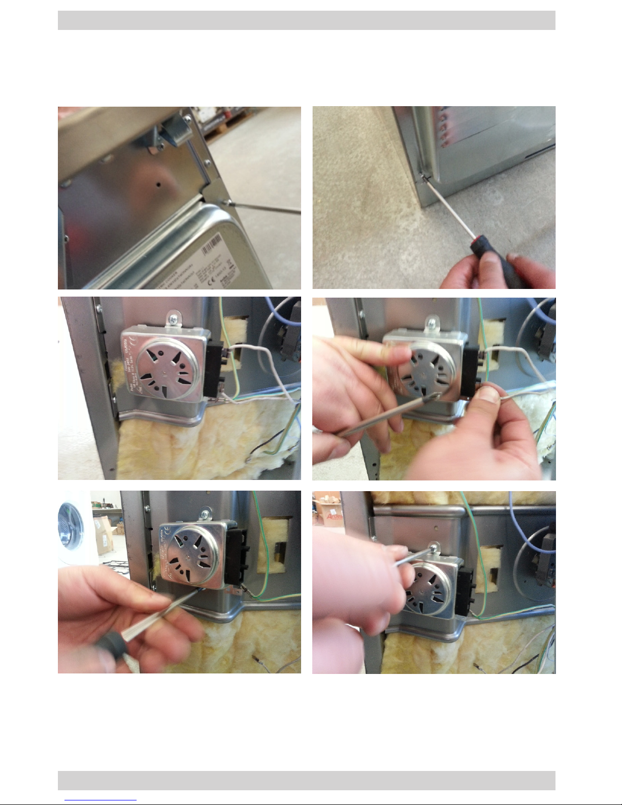
Rotisserie motor assembly
1. Dismantle the rear wall by removing the screws on the sides. Disconnect the wiring harness from the rotisserie motor. Remove the two screws that x the rotisserie motor.
Replacing the rotisserie motor
2. To reassemble the components follow the above steps in reverse order.
Page 16
16
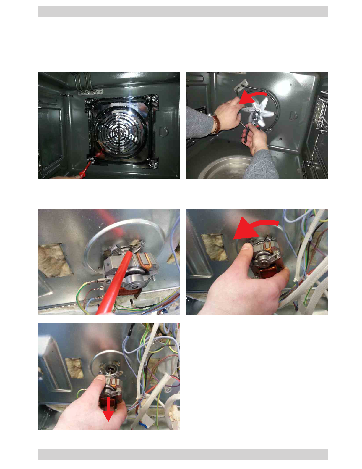
Convection fan assembly
1. Remove the rear wall according to relevant instructions in the manual. Remove
the fan guard by removing the screws. Remove the fan propeller by holding the
fastening nut with the pliers and rotating propeller.
Dismantling the fan
3. To reassemble the components follow the above steps in reverse order.
2. Remove the fan drive by bending the locking tab. Then turn counter-clockwise
and pull the fan drive toward you. Disconnect the fan drive wiring harness.
Page 17
17
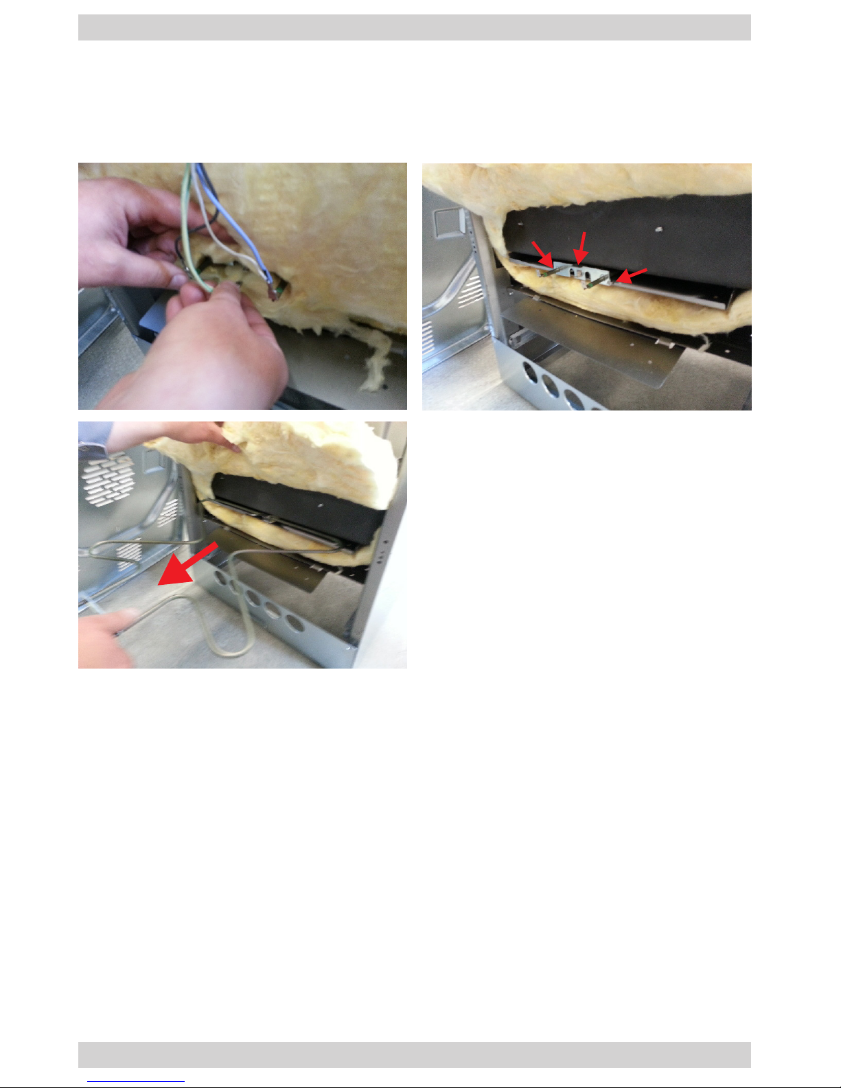
Bottom heater
1. Dismantle the rear wall by removing the screws on the sides. Disconnect the wiring harness from the heater. Gently remove the oven insulation, pay special attention not to damage (delaminate) the insulation. Using a at screwdriver, gently
deect the catches securing the heater. Slide the heater toward yourself.
Dismantling the bottom heater
2. To reassemble the components follow the above steps in reverse order.
Page 18
18
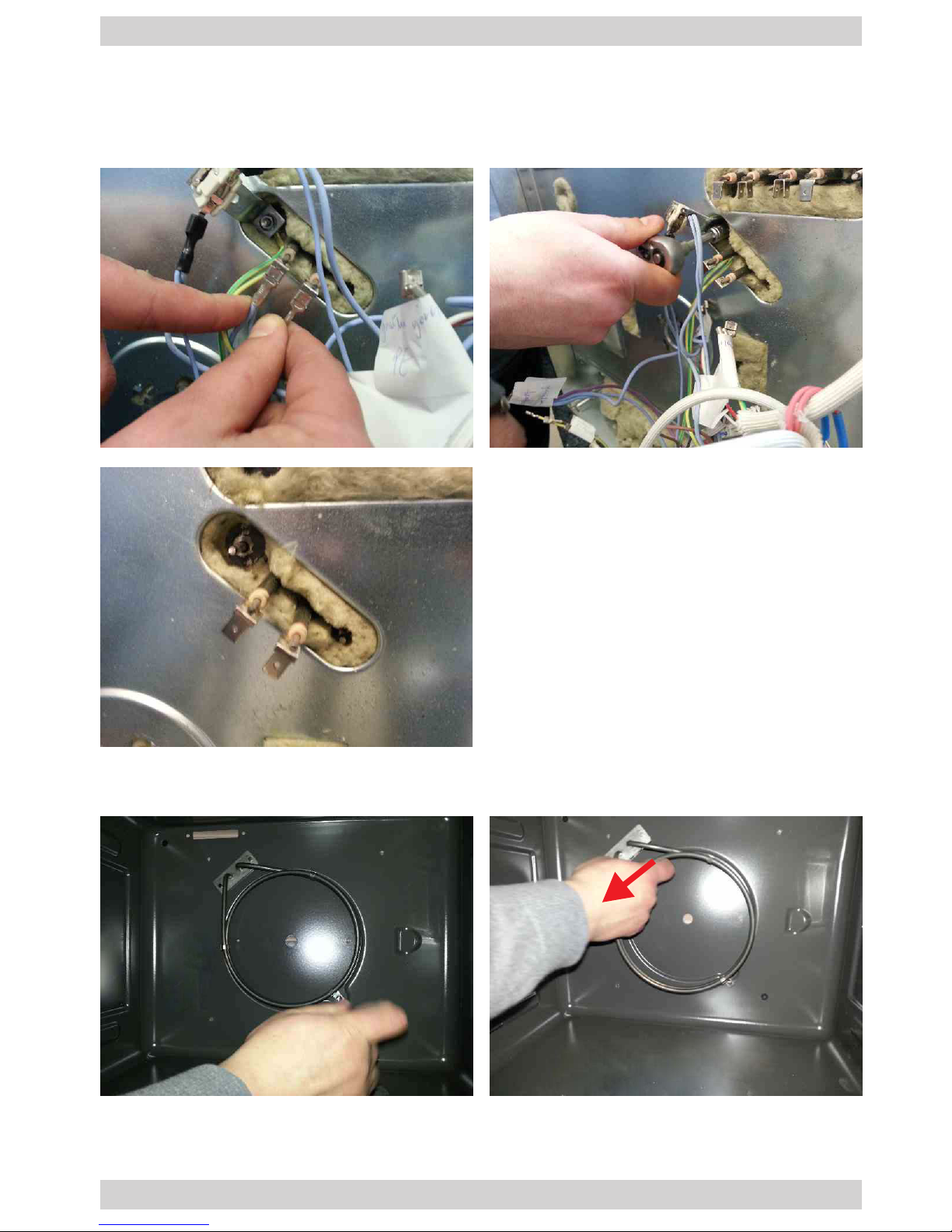
Convection fan heater
1. Remove the rear wall and the fan guard according to relevant instructions in the
manual. Disconnect the wiring harness from the convection fan heater. Using a
socket head wrench undo and remove the nut securing the heater assembly.
Dismantling the convection heater
3. To reassemble the components follow the above steps in reverse order.
2. Inside the oven chamber, remove the screw securing the heater and pull the
heater toward yourself.
Page 19
19
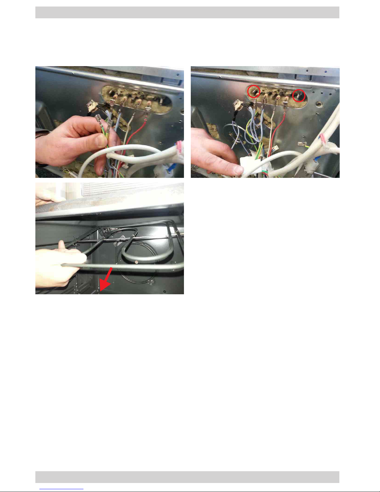
Top heater
1. Remove the rear wall according to relevant instructions in the manual. Disconnect the wiring harness of the top heater. Remove the nuts securing the heater to
the oven chamber. After unscrewing, remove the heater from the oven chamber.
Dismantling the top heater
2. To reassemble the components follow the above steps in reverse order.
Page 20
20
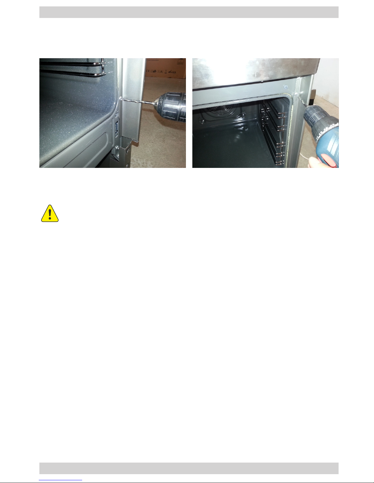
Front wall
1. The rivets that x the front wall to the appliance body must be removed by drilling.
Dismantling the front wall - according to IS-001 service manual
2. To reassemble the components follow the above steps in reverse order.
Install new rivets after the repair that required removal of rivets by drilling.
Do not use screws - the service technician must have a riveter.
Page 21
21
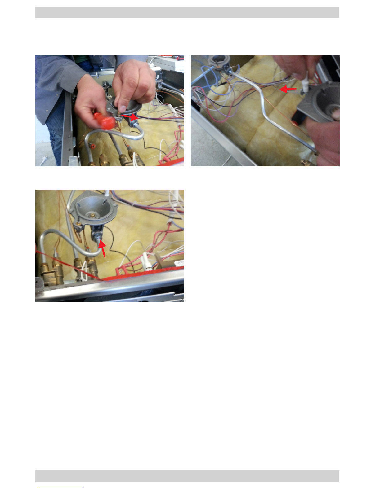
Fittings (gas cooker)
1. Dismantle the hob, spark igniter and thermocouple according to relevant instructions in the manual.
Replacing the burner body
2. Disconnect the pipe that supplies gas to the burner body.
3. To reassemble the components follow the above steps in reverse order.
Page 22
22
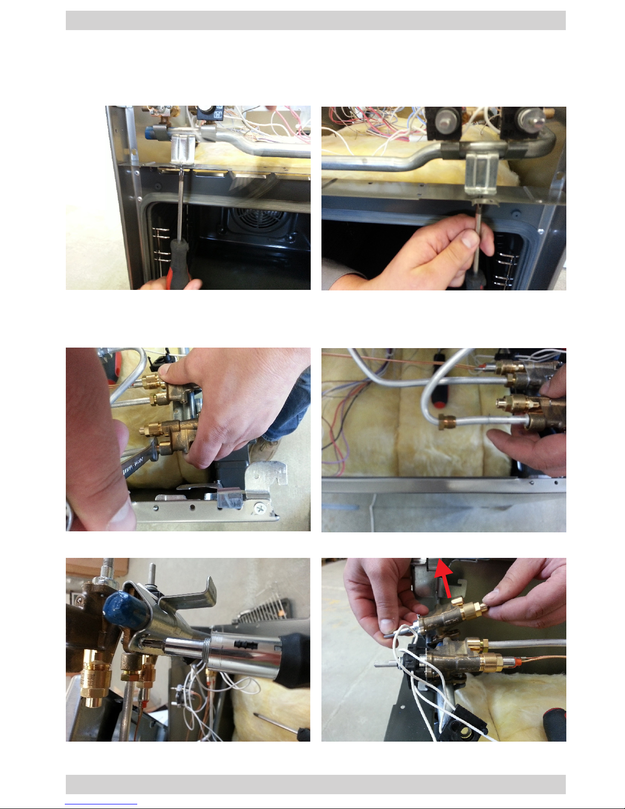
Fittings (gas cooker)
1. Dismantle the hob, dismantle the front panel assembly. After dismantling or opening the door, remove the two screws that x the gas pipe assembly to the cooker
body.
Replacing the valve
2. To replace the gas valve, disconnect the thermocouple according to relevant instructions in this manual, disconnect the pipe that supplies gas to the burner
body.
3. Remove the screw that xes the valve, dismantle the valve by lifting it.
4. To reassemble the components follow the above steps in reverse order.
Page 23
23
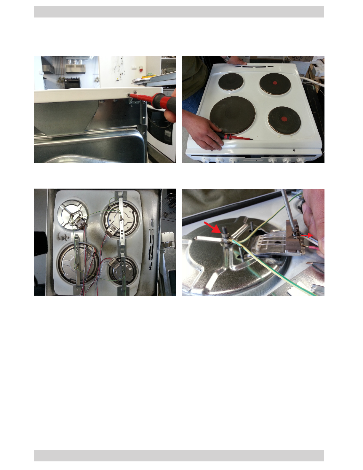
Hob assembly (electric cooker)
1. Remove the screws that x the hob in order to dismantle the hob. Slide the hob
toward the back.
Replacing the cooking zones
2. Place the hob upside-down. To dismantle the cooking zone, undo the nut that
xes the cooking zone and disconnect the wiring harness.
3. To reassemble the components follow the above steps in reverse order.
Page 24
24
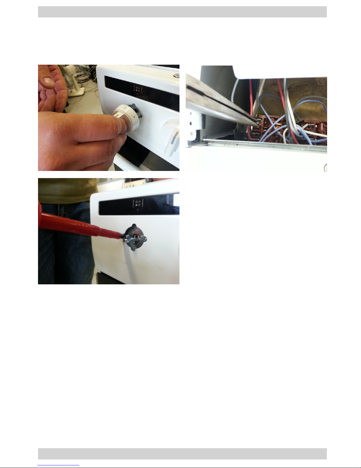
Cam connector of the hot plate (electric cooker)
1. Dismantle the hob, remove the knob by pulling it toward yourself. Disconnect the
wiring harness. Remove the screws that x the cam connector of the hot plate.
Slide the connector out.
Replacing the cooking zones
2. To reassemble the components follow the above steps in reverse order.
Page 25
25
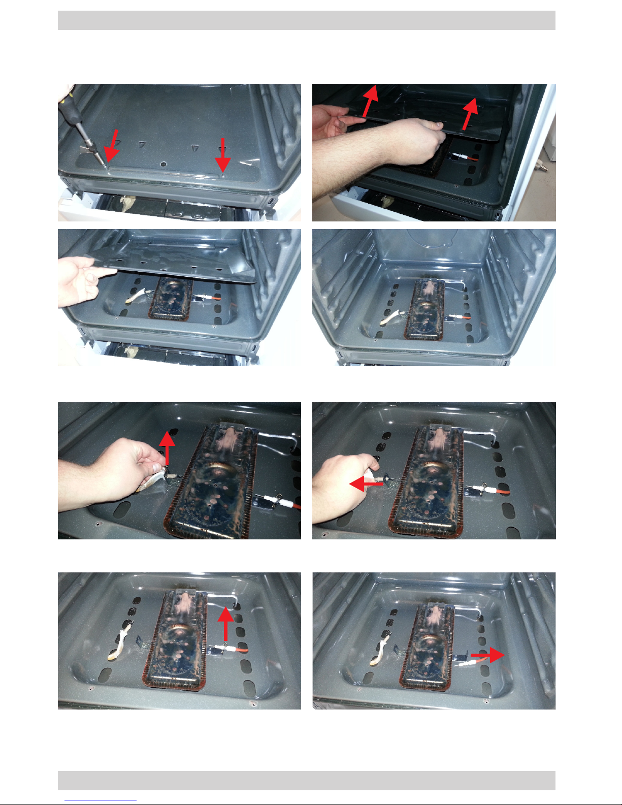
Replace the oven burner (gas hob, gas oven)
1. Remove the door following the relevant instructions in the manual.
2. Unscrew the two screws that secure the oor of the oven, then lift the oor and
pull it towards you.
3. Remove the thermocouple wire clip and pull the thermocouple from its holder.
4. Remove the gas spark igniter wire clip and pull the igniter from its holder.
Page 26
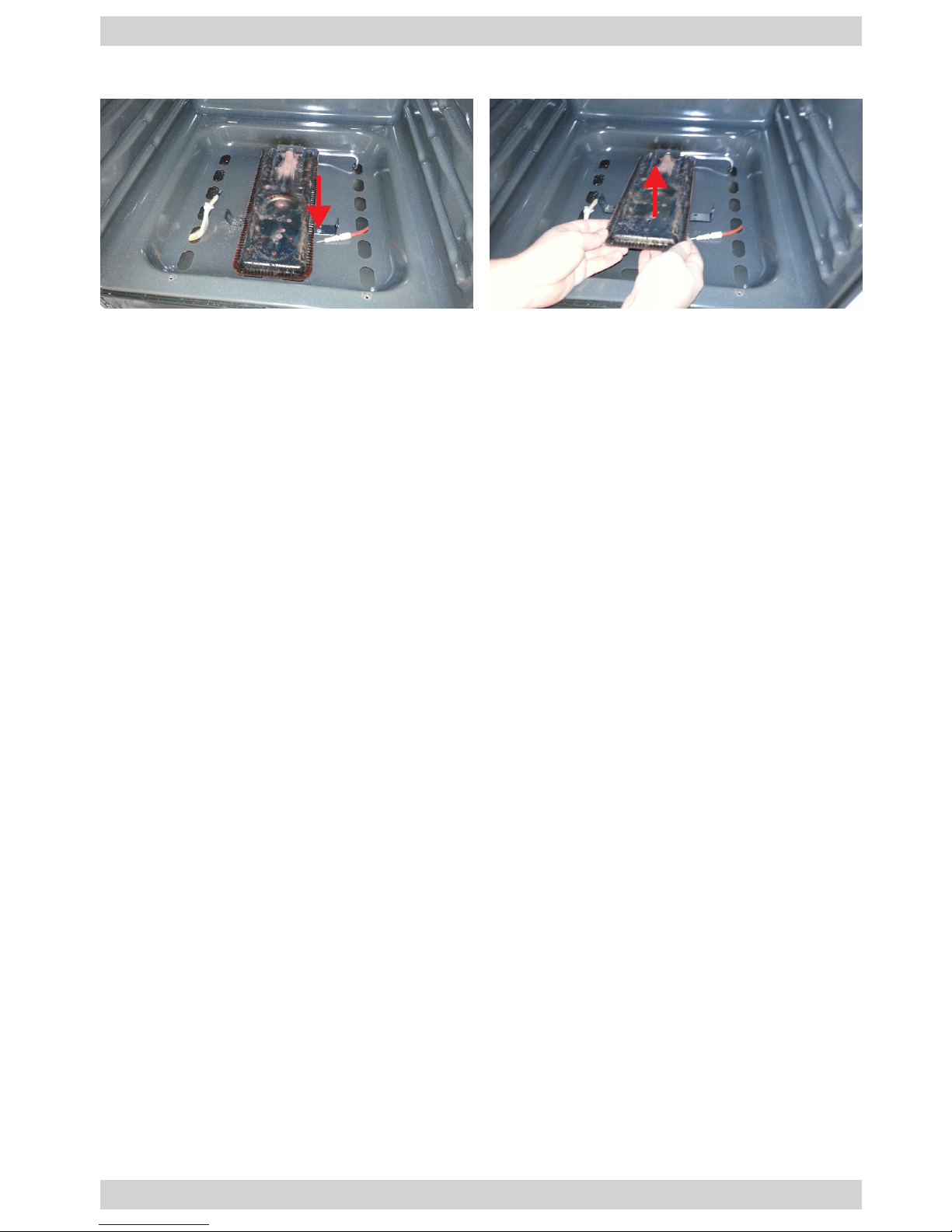
26
Replace the oven burner (gas hob, gas oven)
5. Unscrew the screw securing the burner, lift it and pull it towards you.
Page 27
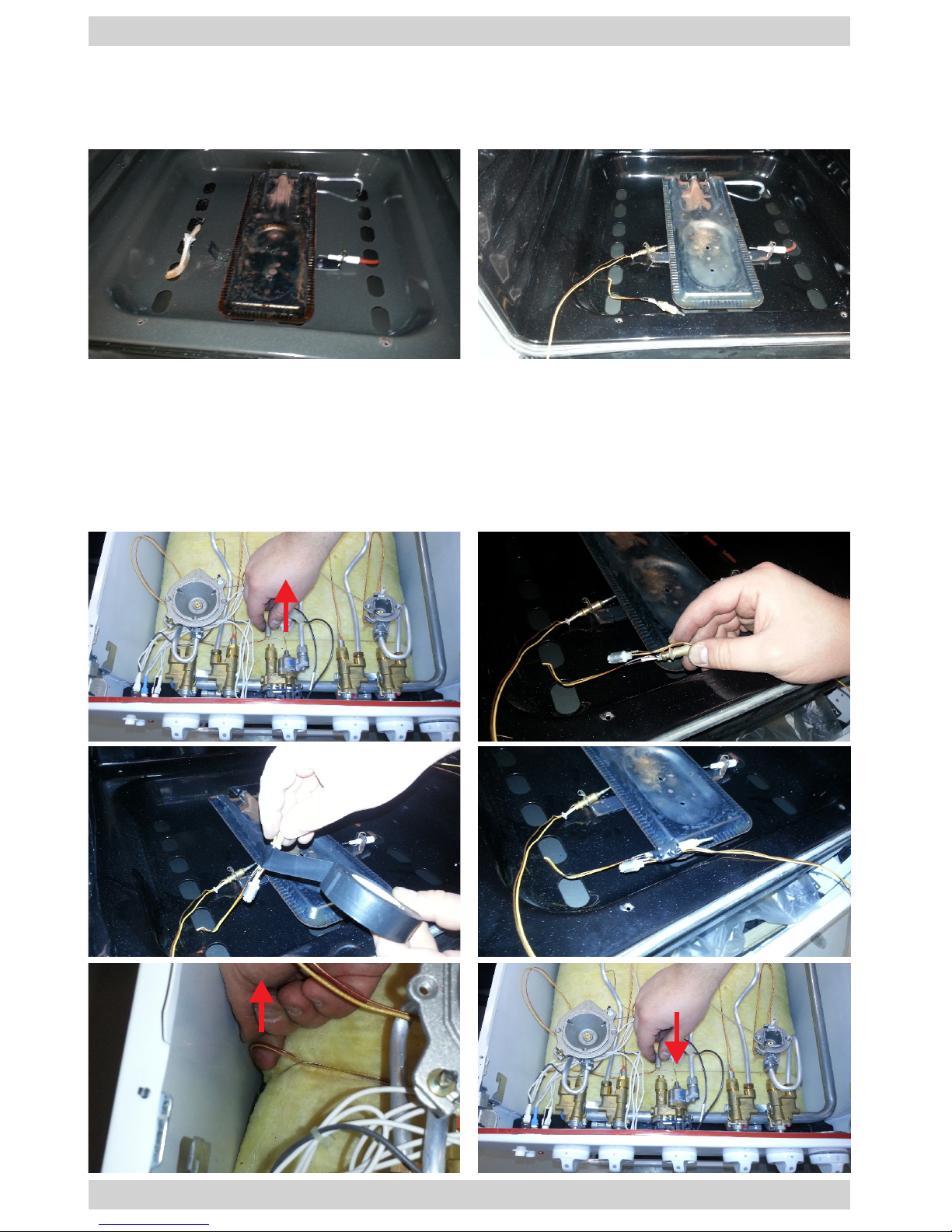
27
Replace the oven thermocouple (gas hob, gas oven)
1. Remove the oven door and the oor following the relevant instructions in the
manual. Remove the work plate.
2. Remove the thermocouple wire clip and pull the thermocouple from its holder.
3. Install a new thermocouple by securing it in the holder using the wire clip.
4. Disconnect the old thermocouple.
5. Connect the socket of the new thermocouple to the end of the old one using the
insulation tape. The bond must be strong enough, so that it does not break when
pulling the wires.
6. Pull the new thermocouple wire through by pulling on the wire of the old thermocouple in the gap between the oven chamber and the side wall.
7. Connect the new thermocouple.
Page 28

28
Replace the oven spark igniter (gas hob, gas oven)
1. Remove the oven door and the oor following the relevant instructions in the
manual.
2. Remove the gas spark igniter wire clip and pull the igniter from its holder.
3. Install a new spark igniter by securing it in the holder using the wire clip.
4. Unscrew the cooker rear wall.
5. Unplug the igniter from its socket.
6. Replace the spark igniter following the same steps as when replacing the thermocouple, i.e. bond the wiring of the new spark igniter with the wiring of the old one
and then pull it though in the gap between the oven chamber and the side wall
(page 34).
Page 29

Page 30

30
Page 31

31
Page 32

IS-003.2_EN
(05.2014)
 Loading...