


Installation of the We.R™ System
3. Installation of the We.R™ System
3.1.Prerequisites
Prior to the installation and setup of the We.R™ system, the following items need to be prepared:
This document is best read with Adobe Acrobat Reader® version 10.0 (or higher), available for free download at: http://get.adobe.com/reader/.
An electronic format (PDF) version of this manual is available, for free download, at: http://www.essence-grp.com/pages/WeR/WeRFullUserGuide.
AA-size Alkaline batteries for the kit components (10 for the standard kit).
Notes: More batteries might be needed in case additional components were purchased.
Special batteries: the Central Control Unit’s backup battery and the Remote Control Unit’s coin-battery are included in the kit.
A personal computer (PC) with internet access and up-to-date browser application software (Microsoft™ Internet Explorer® 7 or higher, Firefox® 4 or higher, Google’s Chrome™ browser).
The Microsoft® Silverlight™ web application framework should also be installed on the PC. It is available for free download from: http://silverlight.net.
The Service Provider’s web server address for the We.R™ Web Application software (provided by the We.R™ distributor/Service Provider).
If cellular communication is to be used – a SIM-card provided by the distributor or purchased from a Service Provider.
Notes: Distributor (or Service Provider) of the SIM-card should also provide a 4-digit APN code for mobile access. In special cases more APN data (see details on page 43) might be needed.
We.R™ System User Guide |
29 |

Installation of the We.R™ System
A smartphone (optional) for remote system management.
A small screwdriver.
The Central Control Unit’s identification serial number should be registered prior to the installation process.
Stickers with the serial number can be found inside the battery/SIM-card cavity and under the Central Control Unit’s base as illustrated in Figure 4 below.
Figure 4: CCU Serial Number Locations
Note: You may also want to register this serial number in Appendix H Owner’s Records of this User Guide (page 301) where important data of your system is aggregated for future reference.
This chapter of Installation of the We.R™ System provides information about each and every component of the system including its installation, power-up, configuration, integration into the system and operation.
30 |
We.R™ System User Guide |
Installation of the We.R™ System
It is arranged in the exact same sequence the system needs to be built-up, including the steps of software installation and registration. Therefore, it is advised to follow this sequence to ensure properly functioning system.
The We.R™ system is based on independent components described below.
The order of presenting these components is the recommended order of their installation.
Note: Except for the Central Control Unit, not all the below-mentioned components must be installed for a functional alarm system.
3.2.The Central Control Unit – ES8000CP
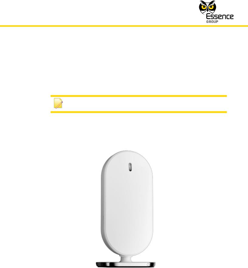
The center-piece of the We.R™ system is the Central Control Unit (CCU or CP).
Figure 5: The Central Control Unit
We.R™ System User Guide |
31 |

Installation of the We.R™ System
It is a two-way, wireless Central Control Unit comprising the main element of the We.R™ system.
3.2.1.The Central Control Unit Function
The Central Control Unit (CCU) is responsible for wireless communication with the array of We.R™ sensors/detectors, remote access and interface devices internally (within the premises), through the RF communication channel, as well as communications with the external cloud computing services system, through the Internet or cellular channels.
The CCU incorporates the following functions:
Two-way secured communications (AES encrypted) with the We.R™ system's peripherals.
Plug-and-Play Internet (IP) connectivity.
Optional, built-in GSM/GPRS/EDGE quad-band (850/900/1800/1900MHz) modem.
Supporting transfer of high quality, high resolution, color pictures.
Traffic Usage – Simple Event/Command: 200-300 Bytes (text), Streaming Event: 200250 Kbytes (25 Frames).
Supports automatic over-the-air software upgrade programming and configuration.
Rechargeable backup battery.
3.2.2.Installing the Central Control Unit
As mentioned in the above paragraph 2.3.3, prior to the installation of the CCU the following items must be prepared:
The CCU’s backup battery.
A PC connected to the Internet and running browser application software.
The LAN cable (in case the Internet is to be used as external CCU communication channel).
The SIM-card provided by the Service Provider (in case the CCU is to be communicating via the cellular channel) with its 4-digit APN code (other APN data might be required too, see details on page 43).
A smartphone (optional).
32 |
We.R™ System User Guide |

Installation of the We.R™ System
Registration of the CCU’s serial number (see page 30) should also be completed.
3.2.2.1. CCU Positioning Recommendations
The CCU should be installed on:
A flat surface.
In a central home/office location with:
Unshielded adequate cellular coverage (if cellular communication is to be used).
Close to an Internet connection outlet (modem/router connection, if Internet communication is to be used).
The CCU must be activated and the system must be registered with the Service Provider (or the distributer) to enable its proper operation.
The following need to be executed for the setup and activation of the CCU:
1.Remove the back cover of the CCU to reveal the battery/SIM-card compartment.
2.In case cellular is intended to be used for external communication – insert the SIM-card, with its contacts facing down, as illustrated in Figure 6 below.
Note: Refer to the graphic representation of the SIM-card engraved onto the plastic bottom of the cavity, next to the card’s designated location.
Figure 6: Insertion of the SIM-card
We.R™ System User Guide |
33 |

Installation of the We.R™ System
3.In case the Internet is intend to be used as the primary external communication channel:
Plug the LAN cable into the RJ45 socket on the back panel of the CCU and its other end into a network socket (in the Internet router or modem).
LED 2
LED 1
Figure 7: Insertion of LAN Cable into the CCU Socket
The CCU back panel LAN (RJ45) socket provides two (2) LED status indications, active in accordance with the IEEE 802.3u standard, as a convenient means of determining the mode of operation of the network:
i.LED1 (Green) is the Link Activity LED.
It will lit steady once the network transceiver detects a valid link and will blink upon link activity (transmit/receive).
ii.LED2 (Amber) is the Link Speed LED.
It will turn ON once the detected link speed is 100Mbit/Sec and will turn OFF once the detected link speed is 10Mbit/Sec. A blinking LED2 indicates communication collision.
4.If there is no Internet connection available or the LAN cable is not connected, the SIM-card will be used as the primary connection channel between the We.R™ system and the We.R™
server.
Note: If both the SIM-card and the LAN cable are installed, the Internet will be the primary communication method and the cellular channel will be used for backup.
34 |
We.R™ System User Guide |

Installation of the We.R™ System
5. Insert the backup battery into the battery cavity, above the SIM-card.
Note: Battery’s label should be facing up and the battery’s contacts – aiming towards the base of the CCU.
Figure 8: Insertion of the Backup Battery
6.Return the battery cover back to place.
7.Plug the Power Supply's cable into the mini-USB™ connector on the back of the CCU.
8.Plug the adapter’s cube into an electric power outlet socket.
The LED on the front panel of the Central Control Unit should light with orange color.
9.Place the CCU in its designated location.
10.Wait for the CCU’s front panel LED to switch from orange to green color before continuing to sub-paragraph 3.2.3 below.
We.R™ System User Guide |
35 |

Installation of the We.R™ System
Notes: The LED switching from orange to green indicates that the CCU is properly active. It takes approximately 5 minutes for the LED to switch.
The Central Control Unit is now ready for the next step of registration and setup.
Note: The initial registration is a web-only procedure and therefore could be exercised utilizing the Web Application only (cannot be done with the Mobile Application).
3.2.3.Activating the Central Control Unit
Notes: This paragraph details the initial registration process of the system, utilizing the We.R™ Web Application software. It is a one-time procedure exercised as part of the activation of the system’s Central Control Unit. The We.R™ Web Application is a comprehensive software package dealing not only with this initial registration procedure but with all aspects of administrating the We.R™ system (Status reports, peripheral devices’ add/remove and setup, events history, etc.). It is, therefore, recommended to read paragraph 3.3 The We.R™ Web Application below prior to the activation of the CCU.
Activation of the CCU begins with registration of the We.R™ system with the Service Provider’s web server. Besides introducing the We.R™ system to the server, via the cloud, it also allows the definition of method of mobile communications.
Note: Typing-in the login information (email address and password) and clicking over the  button will be the only action required for subsequent logging onto the We.R™ Web Application.
36 |
We.R™ System User Guide |

Installation of the We.R™ System
The registration procedure is done via the We.R™ Web Application as follows:
1.Utilizing PC running web browser software, go to the We.R™ Web Application by entering the Service Providers’ server address.
Note: You may want to create a short-cut link for this address for ease of future access to the Web Application.
2. The Login window will pop-up:
Figure 9: The We.R™ Web Application Login Window
Note: If prompted, install the Microsoft® Silverlight™ web application framework available for free download at: http://www.microsoft.com/getsilverlight/Get-Started/Install/Default.aspx.
The  button allows selection of the interfacing language.
For the initial registration procedure no information need to be typed into the Email and Password fields.
We.R™ System User Guide |
37 |

Installation of the We.R™ System
The  button will be will be used for subsequent logging into the We.R™ Web Application.
3.Click over the  button only.
A roll-down menu will be added at the bottom of the Login window:
Figure 10: The Login Window with the Roll-down Menu
11.Click over the _Go to first time registration page >>_ option. The First Time Registration (Step 1 of 2) window will pop-up:
Figure 11: CCU First Time Registration Window
38 |
We.R™ System User Guide |
Installation of the We.R™ System
12.Type-in the 8-digits serial number recorded on page 30 (and Appendix H) and click over the  button. The Web Application software performs, at this point in time, a
validation procedure to ensure the number typed is correct.
Clicking over the  button will take you back to the Login window (see above Figure 10).
In case the CCU was previously incompletely registered and this procedure started before the front CCU’s LED switched to green; a Panel Not Connected error message will pop-up:
Figure 12: Panel Not Connected Error Message
In case this serial number was already registered with the system; an Existing Serial Number error message will pop-up:
Figure 13: Existing Serial Number Error Message
In case the serial number typed was invalid; an Invalid Serial error message will pop-up:
Figure 14: Invalid Serial Error Message
We.R™ System User Guide |
39 |
Installation of the We.R™ System
In all the above error cases, clicking over the  button will take you back to the Login window (see above Figure 10).
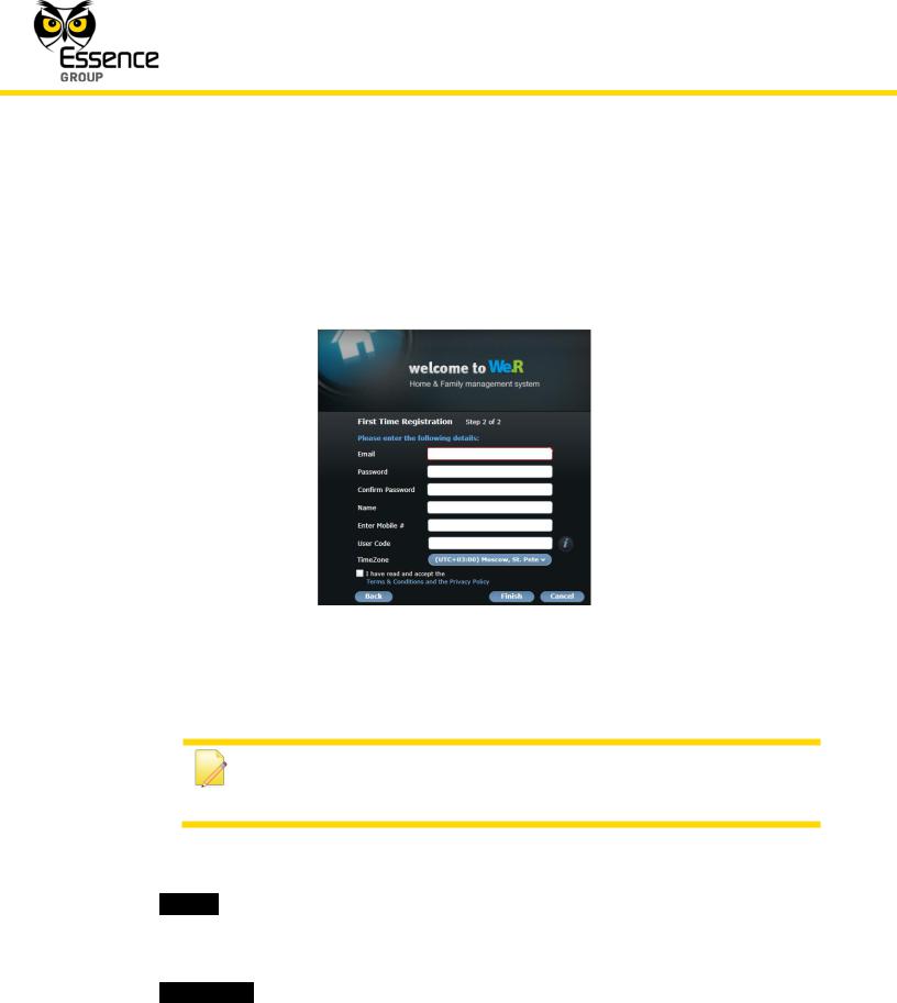
13.In case the number typed is valid, the First Time Registration (Step 2 of 2) window will popup:
Figure 15: First Time Registration Step 2 Window
Note: You may want to record the following registration details
to Appendix H Owner’s Records of this guide (page 301) where important data of your system is gathered for future reference.
14.Type-in your personal details as follows:
i._Email_ – Address where system’s messages and notifications will be sent to via email.
ii.This address will also be used for subsequent login (see above Figure 9).
iii._Password_ – Required for safe login.
40 |
We.R™ System User Guide |

Installation of the We.R™ System
Note: The login password is case sensitive and must have a minimum of six
(6) alphanumeric characters.
This password need to be confirmed (re-typed) in the next field – _Confirm Password_.
The information provided for the above fields will also be used as key-codes for subsequent accesses to the Web Application (see above Figure 9).
iv._Name_ – The User Name you will be identified with in the system. This is a casesensitive, alphanumeric characters’ field.
v._Enter Mobile #_ – Type-in your mobile telephone number.
This data is for information records only (not used at this point in time).
Use digits only in international telephone number format (for example: 972522728110).
vi._User Code_ – For the We.R™ Mobile Application to be installed on a later stage on the smartphone, you are required to initiate a four (4) digits user identification code (an extra password).
vii._TimeZone_ – Select your time-zone from the roll-down menu, to synchronize the system clock for correct email messages and notifications time-stamps.
Note: The Web Application servers are always set to zero (0) UTC time zone (Zulu time).
15.Acknowledge your acceptance of the Terms & Conditions of usage for this software by marking the check-box at the bottom-left side of the window.
A copy of this terms and conditions is attached to this guide as Appendix B End User License Agreement (EULA).
It is also accessible via the link _Terms & Conditions and the Privacy Policy_.
16.Clicking over the  button terminates the process (upon completion).
We.R™ System User Guide |
41 |

Installation of the We.R™ System
Clicking over the  button, throughout the above process, bounces you back to the First Time Registration Page 1 window (see above Figure 11).
Clicking over the  button, throughout the above process, bounces you back to the Login window (see above Figure 10).
17.If no error detected during the above procedure of entering the initial registration data, the following confirmation message will pop-up:
Figure 16: Registration Confirmation Message Window
Within a period of approximately 5 minutes, the CCU’s front LED should turn green and the registration process is concluded.
Notes: If the LED remains orange (does not switch to green), it means that communication could not be established (verified and registered properly), usually due to wrong APN data.
Green flashing LED means the CCU is being updated by the Remote Software Upgrade (RSU) mechanism.
Clicking over the  button will close this message window (but the process of connecting will continue until completed as indicated by the LED switching to green).
42 |
We.R™ System User Guide |

Installation of the We.R™ System
3.2.3.1.Manual Access Point Name Data Registration
In case a problem is encountered during the initial registration procedure, with the Access Point Name (APN) data; you need to contact the SIM-card’s Cellular Operator/Service Provider and get all of the APN data.
This data need to be manually typed into the registration data fields.
This is done by clicking over the _APN Settings Registration >>_ menu option of the roll-down menu added to the Login window (see above Figure 10).
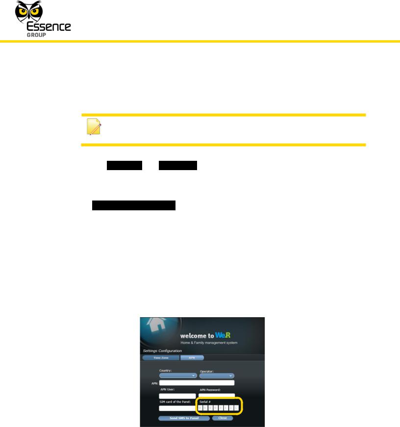
Once the _APN Settings Registration >>_ is clicked over, the APN Settings Configuration window pops-up:
Figure 17: APN Settings Window
Most market available SIM-card’s APN data is pre-programmed into the We.R™ system and being updated on a regular basis, therefore:
1.The automatic process executed following the click over the  button (see lineitem 14 on page 40) should complete the registration process with no problem.
In case the process does not complete properly (the LED did not turn green):
Note: A short-form explanation regarding this process is also available online by clicking over the  button.
We.R™ System User Guide |
43 |
Installation of the We.R™ System
i.Call your cellular Service Provider and obtain all APN data (APN name, APN user and APN password).
Note: You may want to record the APN data to Appendix H of this User Guide where important data of your system is gathered for future reference.
ii.Select the _Country_ and _Operator_ (Cellular Service Provider) from the roll-down menus in the APN Settings Configuration window (see above Figure 17).
iii.Manually type-in all the APN data retrieved from the Cellular Service Provider.
iv.In the _SIM card of the Panel:_ field, type-in the international cellular telephone number of the SIM-card (digits only, no prefix, for example: 972522728110) and the CCU’s serial number (see page 30 and Appendix H) and click over the  button.
v.Wait for the front panel LED to turn green (may take up to 15 minutes).
In case the manual entry of APN data is done for a CCU which was already registered (i.e. upon replacing a faulty SIM-card), the APN Settings Configuration window shown in the above Figure 17 will pop-up with the CCU’s Serial Number already typed-in (but greyed-out) as illustrated in Figure 18 below:
Figure 18: APN Settings Window for a Registered CCU
44 |
We.R™ System User Guide |
 Loading...