

Page 1

Administration of the We.R™ System
We.R™ System User Guide
197
4. Administration of the We.R
Daily usage of the We.R™ system involves:
Basic terms of operation:
Arming modes of operation
Handling alarms
Receiving notifications
Panic situations
Monitoring the premises
Managing Users
Managing Devices
Log of Events (System History)
™
System
4.1. Arming Modes of Operation
The We.R™ system supports four (4) security arming modes for the system.
These arming modes are set individually for each system device participating in the security
arena (see details in paragraph 4.5. Managing Devices below).
Such a setup is done utilizing the We.R™ Web Application’s Devices Page as detailed in
paragraph 4.5. Managing Devices below.
The We.R™ Web Application’s Status/Activation Bar (see Figure 160 below) and the We.R™
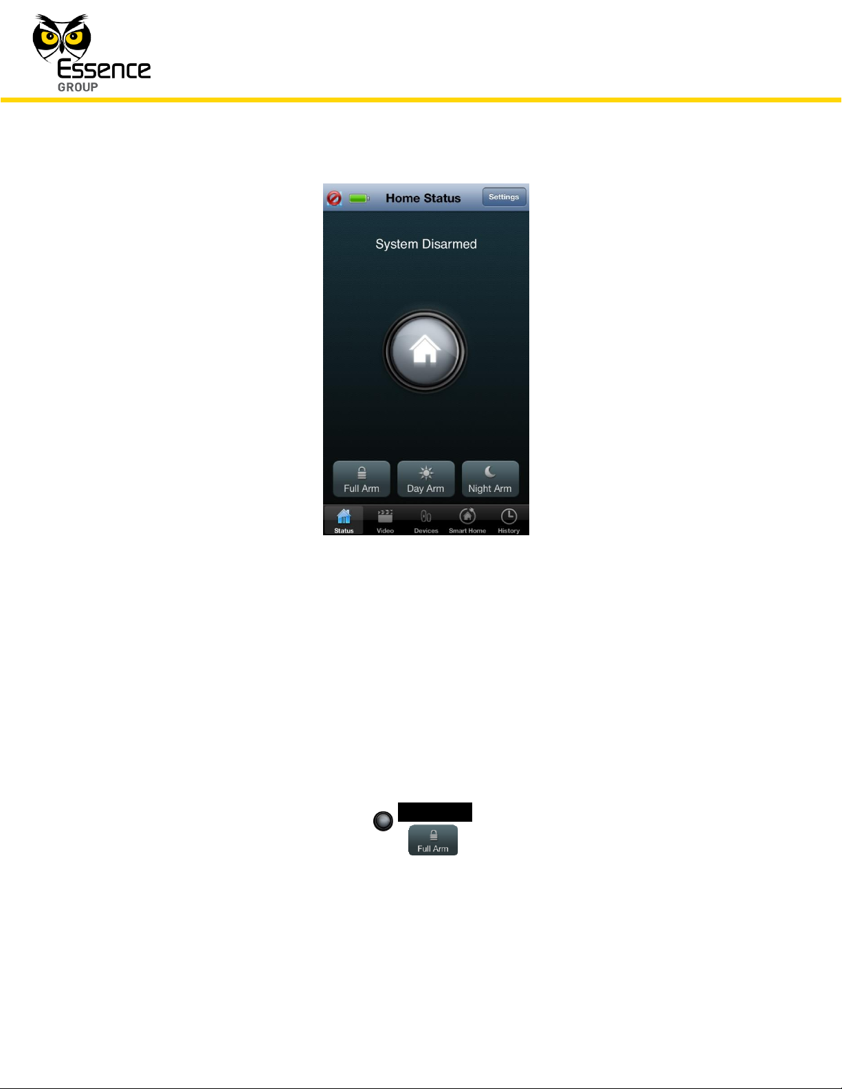
Mobile Application’s Home Status (Main) screen (see Figure 161 below) as well as the Remote
Control Unit (Key Fob) and the Wireless Access Control Reader, provide the tool for triggering
the system arming commands as well as provide the visual status feedback for the User.
Figure 160: The We.R™ Web Application’s Status/Activation Bar
Page 2
Administration of the We.R™ System
198
We.R™ System User Guide
Figure 161: The We.R™ Mobile Application’s Home Status Screen
4.1.1. Types of Security Arming Modes
The We.R™ system provides four (4) possible security arming modes of operation:
4.1.1.1. Full Arm
Simply referred to as – Arm.
Full arm is triggered by clicking over the _Full Arm_ button in the We.R™ Web Application’s
Status/Activation Bar, or by tapping over the button in the We.R™ Mobile Application’s
Home Status screen.
Page 3
Administration of the We.R™ System
We.R™ System User Guide
199
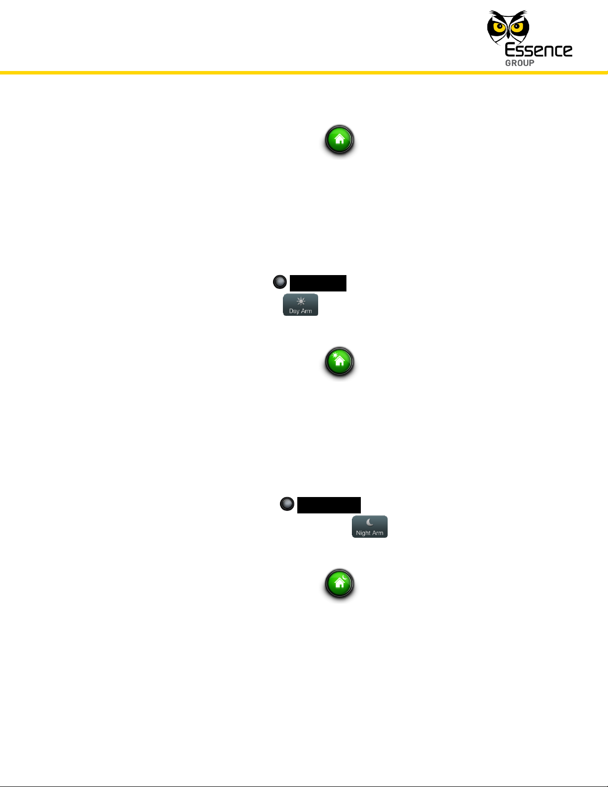
Change of arming status is acknowledged by the status icon.
In this mode of operation, the We.R™ system protects ALL zones. This mode arms all of the
sensor devices on the premises and an alarm will be triggered by any of them upon detecting
an intrusion.
4.1.1.2. Day Arm
Day arm is triggered by clicking over the _Day Arm_ button in the We.R™ Web Application’s
Status/Activation Bar, or, tapping over the button in the We.R™ Mobile Application’s
Home Status screen.
Change of arming status is acknowledged by the status icon.
In this mode of operation, the We.R™ system protects and monitors designated hazardous
zones. This scenario is used mostly for childcare and safety applications, allowing the user to
monitor and protect zones like medicine cabinet, swimming pools, basements, etc.
4.1.1.3. Night Arm
Night arm is triggered by clicking over the _Night Arm_ button in the We.R™ Web
Application’s Status/Activation Bar, or, tapping over the button in the We.R™ Mobile
Application’s Home Status screen.
Change of arming status is acknowledged by the status icon.
In this mode of operation, the We.R™ system protects and monitors designated area on the
premises from intruders. This scenario can arm, for example, only the front door, back door
and balcony.
Page 4
Administration of the We.R™ System
200
We.R™ System User Guide
4.1.1.4. Disarm
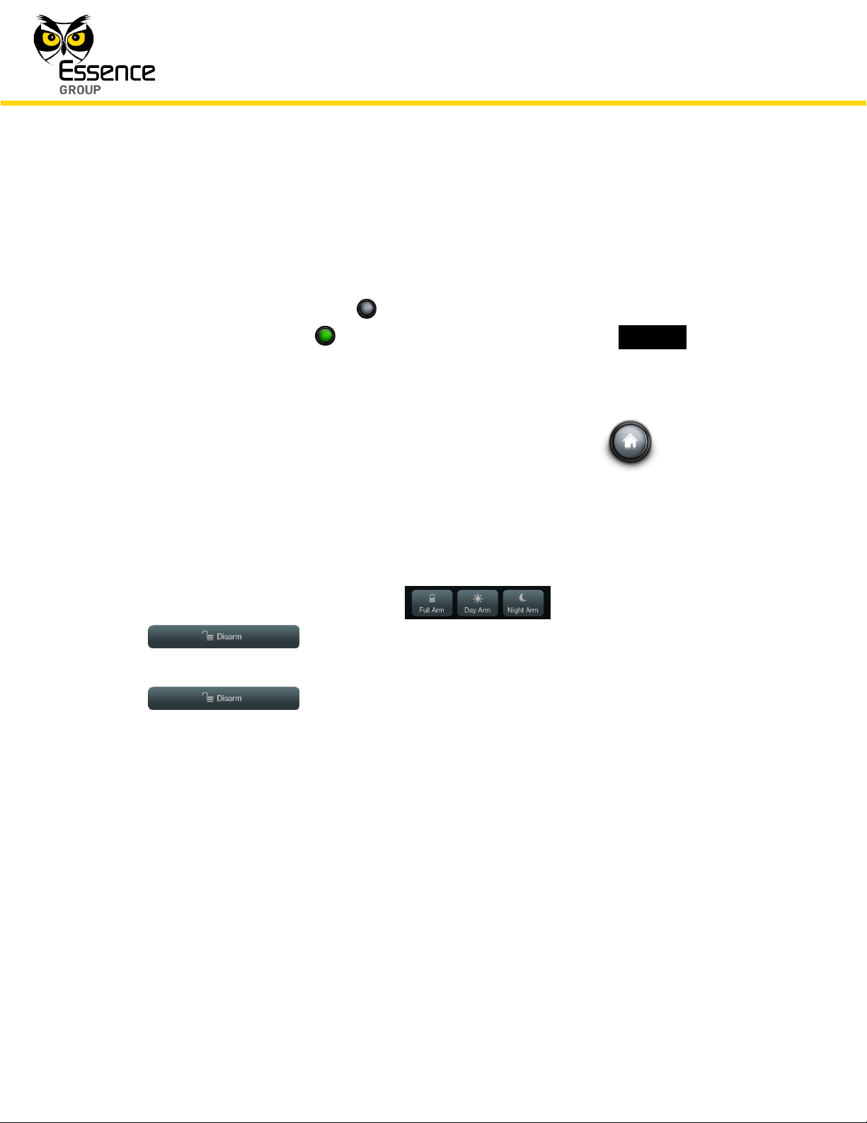
In addition to the above described status icon changing its face and color to acknowledge the
trigger of specific arming mode, the buttons used for the triggering also changes:
The left-most arming button in the We.R
™
Web Application’s Status/Activation Bar
will change its color to green and its title text will change into _Disarm_.
Once changed, clicking over this button again will disarm the system from the specific
arming mode it was triggered for.
Change to disarm mode of operation is acknowledged by the status icon as
well as the triggering buttons returning to the disarm indication (color and text).
When triggering the system into any of the three security arm modes via the We.R
Mobile Application, the three arming buttons at the bottom of the We.R™ Mobile
Application’s Home Status screen ( ) will turn into the
button.
Disarming the system via the We.R™ Mobile Application is done by tapping over this
button.
™
4.1.1.5. Arming/Disarming with We.R
™
System Devices
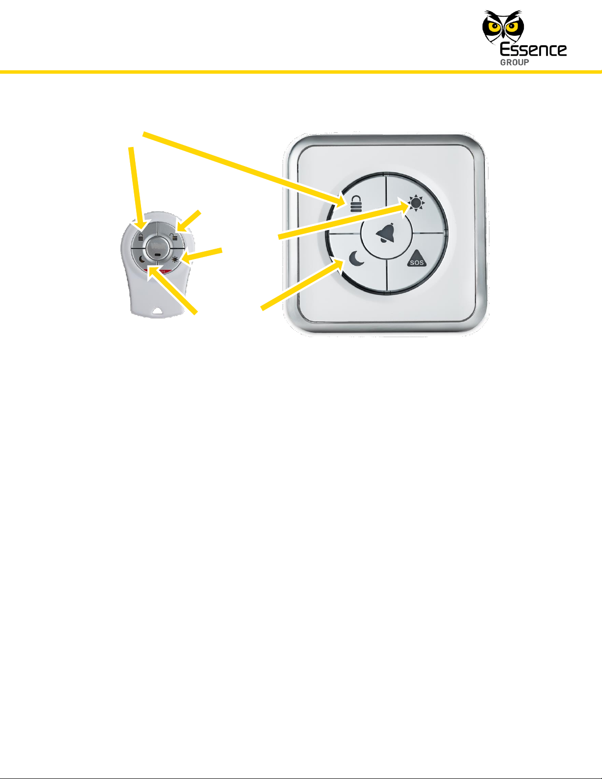
The above detailed security arming modes of operation can also be triggered by the Remote
Control Unit (Key Fob) or the Wireless Access Control Tag Reader devices simply by attaching
the Tag to the Tag Reader (in case a TR5 is used in the system) and or pressing the relevant
keys as demonstrated in Figure 162 below:
Page 5
Administration of the We.R™ System
We.R™ System User Guide
201
Day Arm
Full Arm
Night Arm
Disarm
Figure 162: Triggering Arm Modes with Devices
Disarming with the Wireless Access Control Tag Reader device is done by putting the Tag in
close proximity with the Tag Reader.
4.1.1.6. Force Arming
If attempt is made to arm the system (full arm, night arm and day arm), where one or more of
the sensor devices is opened (i.e. a window/door with a Magnetic Sensor is opened), a
notification about these devices will be given and the system will allow performing a forced
arm. In case of forced alarm, such an opened device will be bypassed by the system.
4.2. Handling Alarms
The We.R™ system may alarm the User with three (3) different types of alarms:
Security Alarms
Safety Alarms
Page 6

Administration of the We.R™ System
202
We.R™ System User Guide
Panic Alarms
4.2.1. Security Alarms
Once the system is armed (full arm or night arm or day arm), an alarm will be triggered in the
following security events:
A Magnetic Sensor (MGL) monitored window/door was opened.
A Motion Detector (PIR) or a Motion Indoor Photo Detector (IPD) detected some motion
within its detection range, or, if any device is tampered while the system is armed.
If a Security Alarm was triggered, the User will receive an Alarm Notification on his We.R™ Web
Application (assuming the User is logged in) and on his smartphone (where the We.R™ Mobile
Application software was installed).
On the We.R™ Web Application’s Status/Activation Bar:
Figure 163: Security Alarm Notification on the We.R™ Web Application
The status icon will blink in red, and
Two buttons will lit in red allowing the User to:
Stop the Siren sound,
Disarm the system.
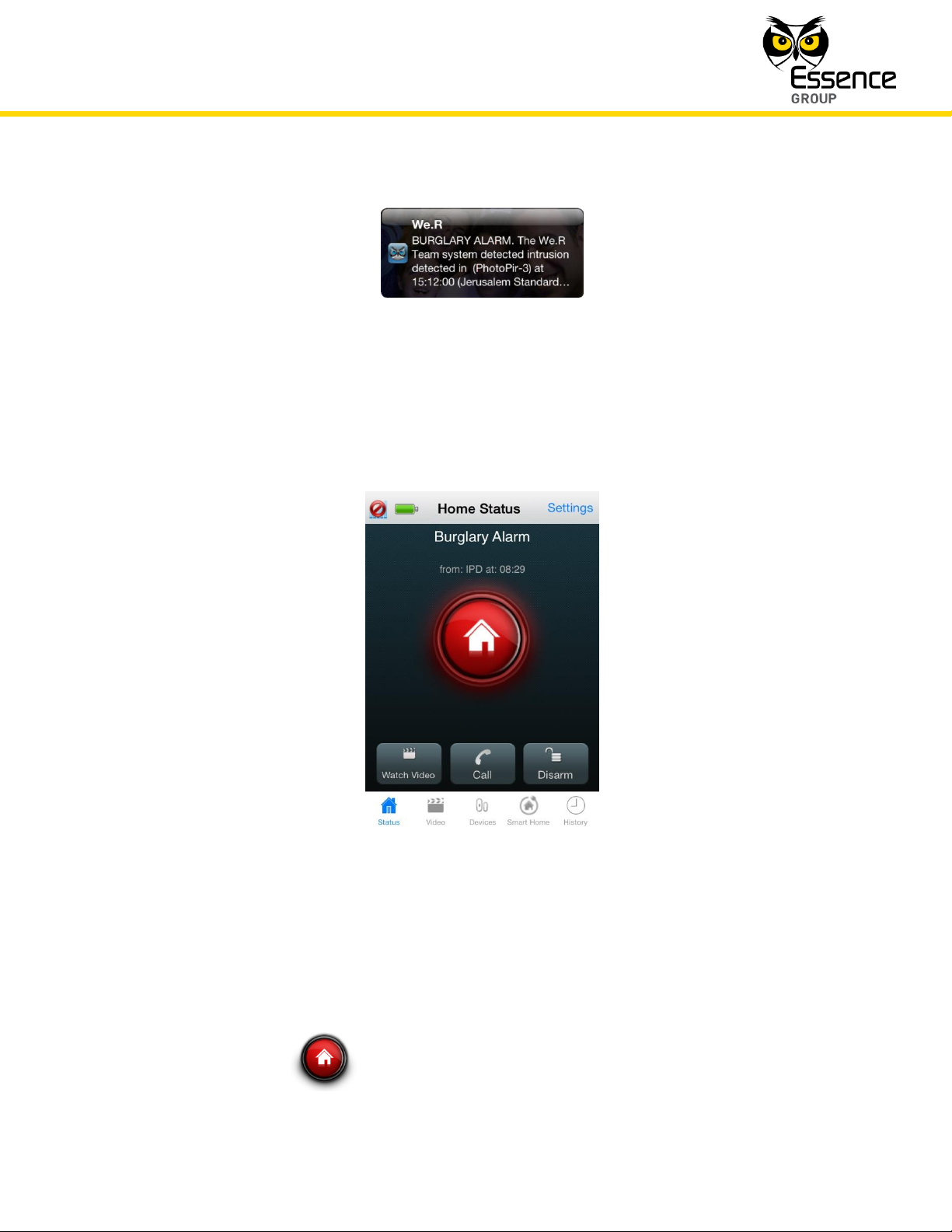
On the We.R™ Mobile Application, the following notification message window will pop-up to
draw the User’s attention:
Page 7
Administration of the We.R™ System
We.R™ System User Guide
203
Figure 164: Security Alarm Notification on the We.R™ Mobile Application
The Home Status screen will display:
Where:
A Burglary Alarm title will be presented along with the triggering device identification
The status icon will blink in red, and
Figure 165: Security Alarm Screen on the We.R™ Mobile Application
and a time stamp.
Page 8
Administration of the We.R™ System
204
We.R™ System User Guide
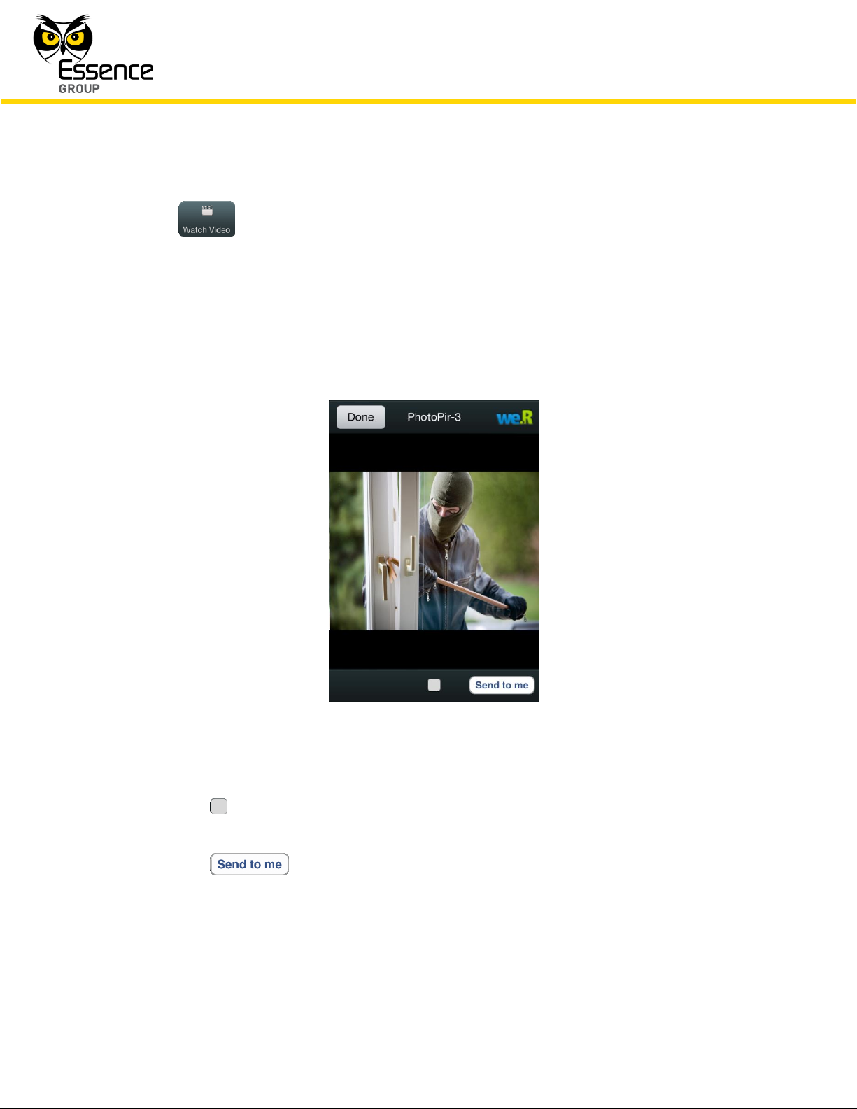
Three (3) new buttons will be presented at the bottom of the screen to allow:
– monitor the premises by watching video-like images taken if the
triggering device was a Motion Indoor Photo Detector (Camera).
Alarms triggered by a Camera allow monitoring of the premises by the image
presentation screen which, upon tapping this button, opens to display the area in
front of the Camera.
Figure 166: Security Alarm Image Presentation Screen
The button at the bottom of the screen switches the display between video-like
and freeze modes of display.
The button sends the captured images to the User email address.
Tapping over this button will pop-up the acknowledgement window:
Page 9
Administration of the We.R™ System
We.R™ System User Guide
205
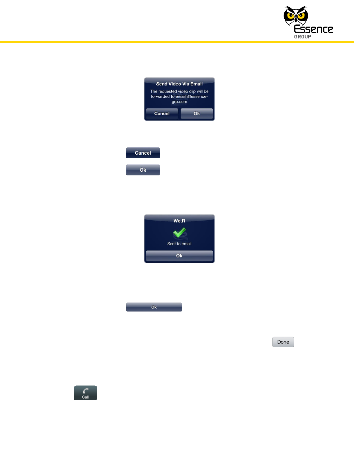
Figure 167: Sending Images to Email Acknowledgement Window
Tapping over the button will terminate the email operation.
Tapping over the button will send the images via email to the User.
Upon completion, the following confirmation message window will pop-up:
Figure 168: Email Confirmation Message Window
Tapping over the button will conclude the send images by mail
operation and return the screen to the Security Alarm Image Presentation Screen
(see above Figure 166).
In the Security Alarm Image Presentation Screen, tapping over the button
will terminate the Camera captured image presentation session and return the
screen to the Security Alarm Screen (see above Figure 165).
– making emergency phone calls from the smartphone,
Page 10
Administration of the We.R™ System
206
We.R™ System User Guide
– disarming the system.
4.2.2. Safety Alarms
Beside security, the We.R™ system also provides for safety features, utilizing devices like the:
Smoke Detector (SK2)
Flood Detector (FL), and
Universal Transmitter interfacing between the We.R
party manufacturers.
Setup, scenarios of operation and alarm notifications of these safety devices are incorporated
into the system by means similar to the security devices. See details in paragraph 4.5.
Managing Devices below.
™
system and safety device from 3rd
If a Safety Alarm was triggered, the User will receive an Alarm Notification on his We.R™ Web
Application (assuming the User is logged in) and on his smartphone (where the We.R™ Mobile
Application software was installed).
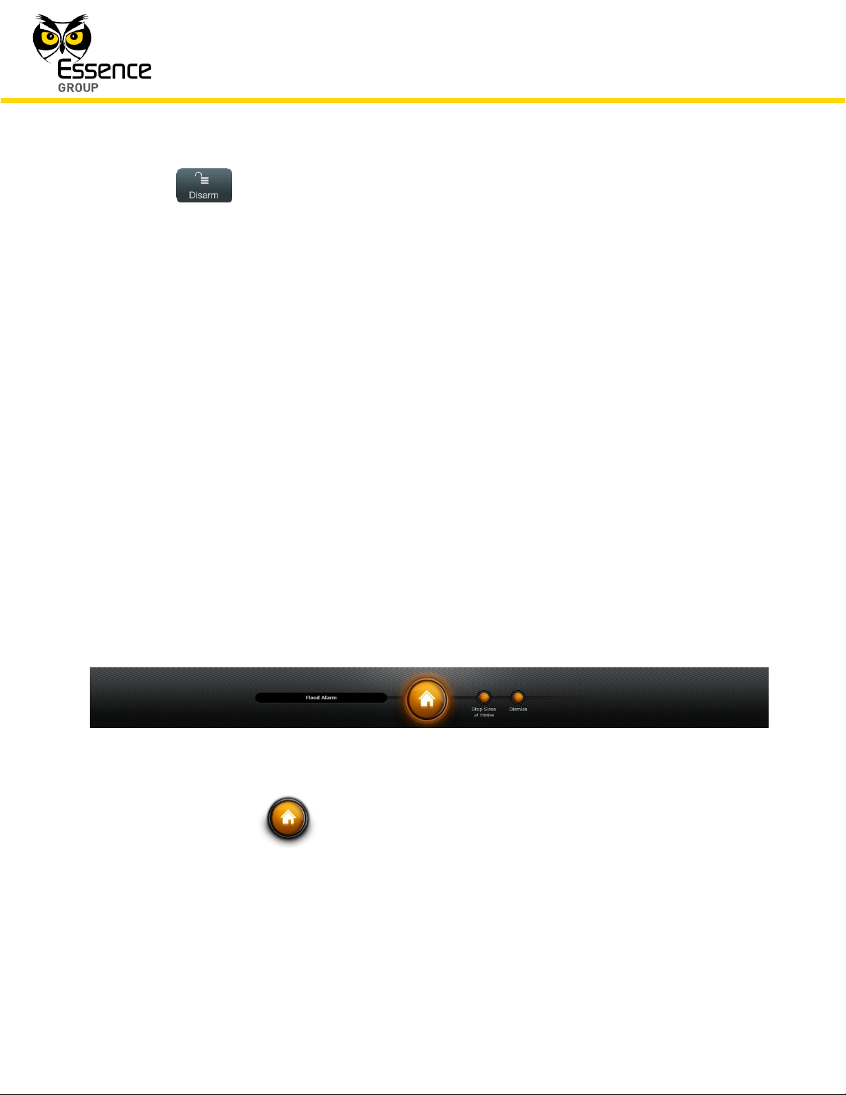
On the We.R™ Web Application’s Status/Activation Bar:
Figure 169: Safety Alarm Notification on the We.R™ Web Application
The status icon will blink in orange, and
Two buttons will lit in orange allowing the User to:
Stop the Siren sound,
Dismiss the alarm and, if the system was armed – disarm it.
Page 11
Administration of the We.R™ System
We.R™ System User Guide
207
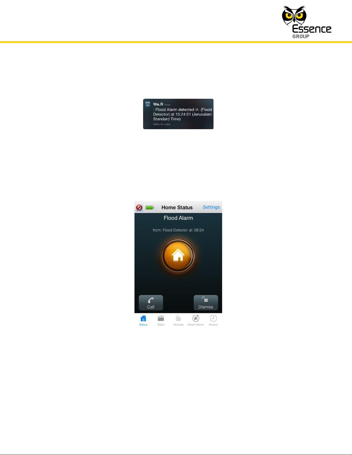
On the We.R™ Mobile Application, the following notification message window will pop-up to
draw the User’s attention:
Figure 170: Safety Alarm Notification on the We.R™ Mobile Application
The Home Status screen will display:
Where:
A Flood (or Smoke) Alarm title will be presented along with the triggering device
Figure 171: Safety Alarm Screen on the We.R™ Mobile Application
identification and a time stamp.
Page 12
Administration of the We.R™ System
208
We.R™ System User Guide
The status icon will blink in orange, and
Two (2) new buttons will be presented at the bottom of the screen to allow:
– making emergency phone calls from the smartphone,
– dismissing the alarm and, if the system was armed – disarm it.
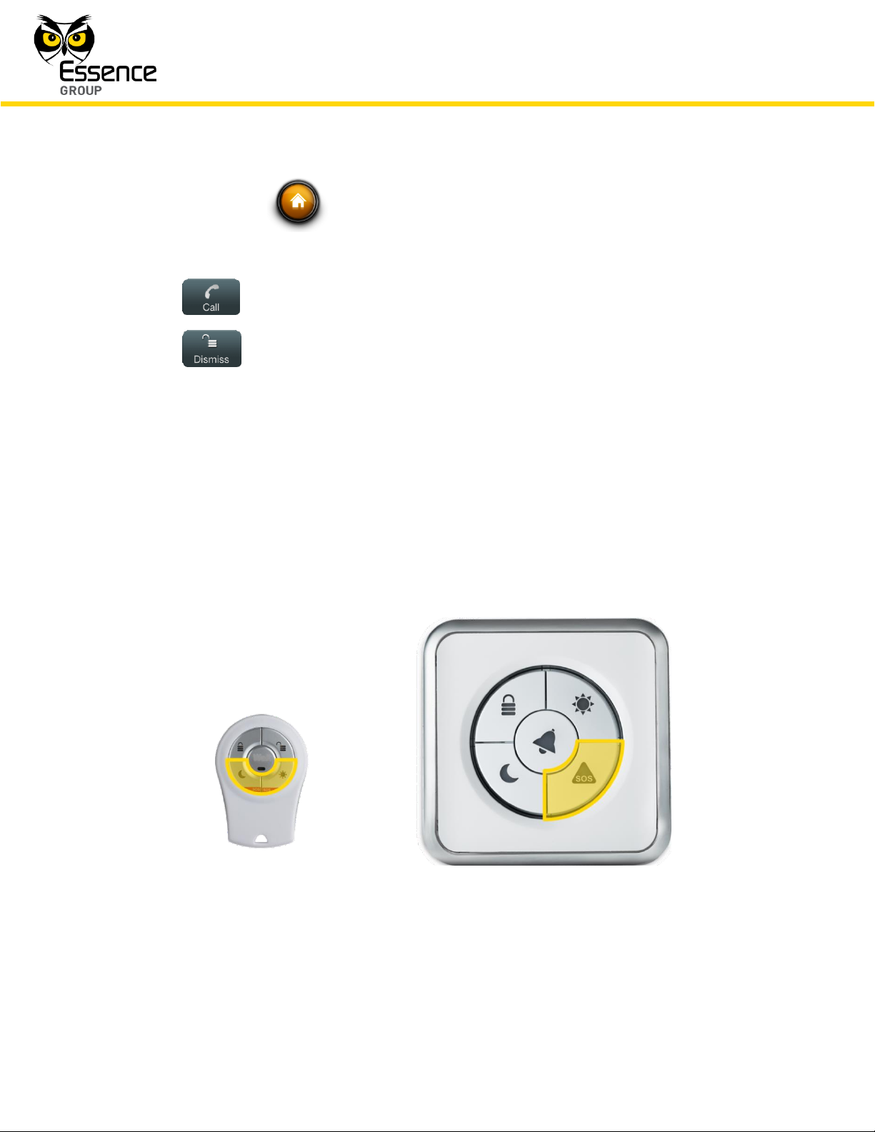
4.2.3. Panic Alarms
The We.R™ system also supports panic alarming for personal emergency cases.
Triggering of panic alarm is done manually by the User either by simultaneously pressing the
Remote Control Unit (Key Fob) two buttons marked with red or by pressing the Wireless
Access Control Tag Reader’s button marked with SOS.
Figure 172: Panic Alarm Triggering Devices and Buttons
No setup or scenarios of operation need to be established for this type of alarms.
Page 13
Administration of the We.R™ System
We.R™ System User Guide
209
If a Panic Alarm was triggered, the User will receive an Alarm Notification on his We.R™ Web
Application (assuming the User is logged in) and on his smartphone (where the We.R™ Mobile
Application software was installed).
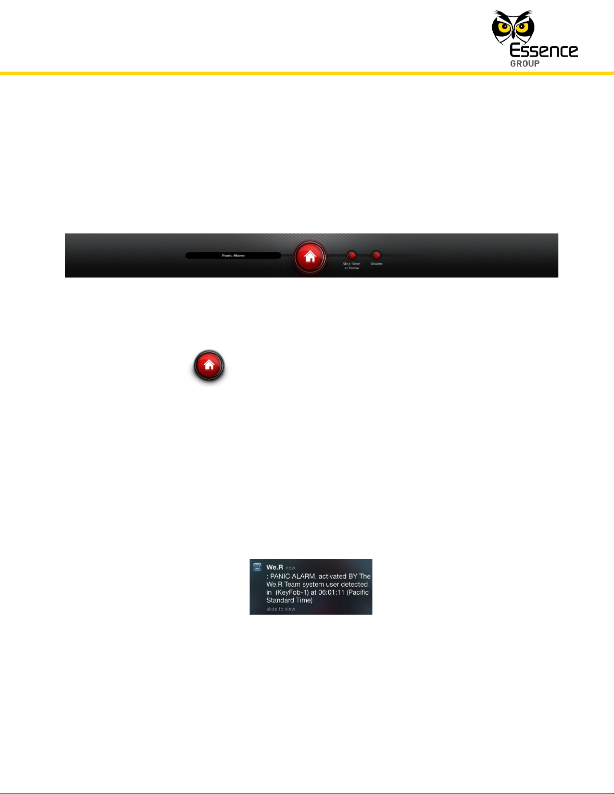
On the We.R™ Web Application’s Status/Activation Bar:
Figure 173: Panic Alarm Status Display on the We.R™ Web Application
The status icon will blink in red, and
Two buttons will lit in red allowing the User to:
Stop the Siren sound,
Disarm the triggering device and the system.
On the We.R™ Mobile Application, the following notification message window will pop-up to
draw the User’s attention:
Figure 174: Panic Alarm Notification in the We.R™ Mobile Application
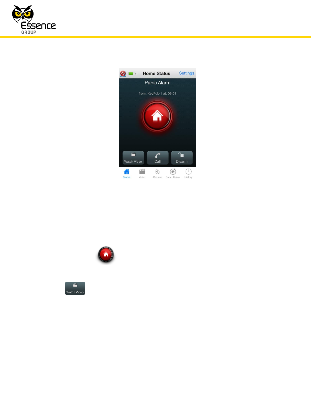
The Home Status screen will display:
Page 14
Administration of the We.R™ System
210
We.R™ System User Guide
Figure 175: Panic Alarm Home Status Screen
Where:
A Panic Alarm title will be presented along with the triggering device identification and a
time stamp.
The status icon will blink in red, and
Three (3) new buttons will be presented at the bottom of the screen to allow:
– monitoring the premises by watching video-like images taken by the
Motion Indoor Photo Detectors (Cameras).
Panic Alarms allow monitoring of the premises by a process similar to the
Monitoring the Premises process (comfort video, see paragraph 4.3. below).
Tapping over this button will open the Last Security Videos selection screen:
Page 15
Administration of the We.R™ System
We.R™ System User Guide
211
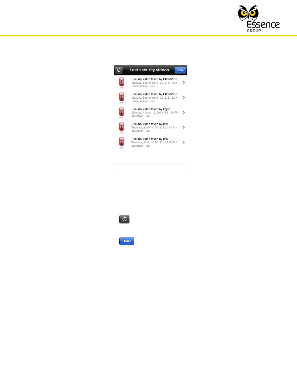
Figure 176: Last Security Videos Selection Screen
Where:
Tapping over the button refreshes the displayed list of available videos
and their related data (triggering device, time stamp, etc.).
Tapping over the button terminate this Watch Video procedure and
switches the display back to the Home Status Panic Alarm Screen (see
Figure 175 above).
Tapping over the arrow () to the right of the selected last taken video will
open the Camera Display screen (see Figure 177 below) and present the
selected images/video:
Page 16
Administration of the We.R™ System
212
We.R™ System User Guide
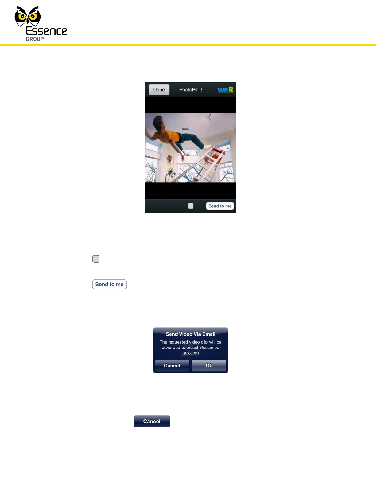
Figure 177: Camera Display Screen
The button at the bottom of the screen switches the display between video-like
and freeze modes of display.
The button sends the captured images to the User email address.
Tapping over this button will pop-up the acknowledgement window:
Figure 178: Sending Images to Email Acknowledgement Window
Tapping over the button will terminate the email operation.
Page 17
Administration of the We.R™ System
We.R™ System User Guide
213
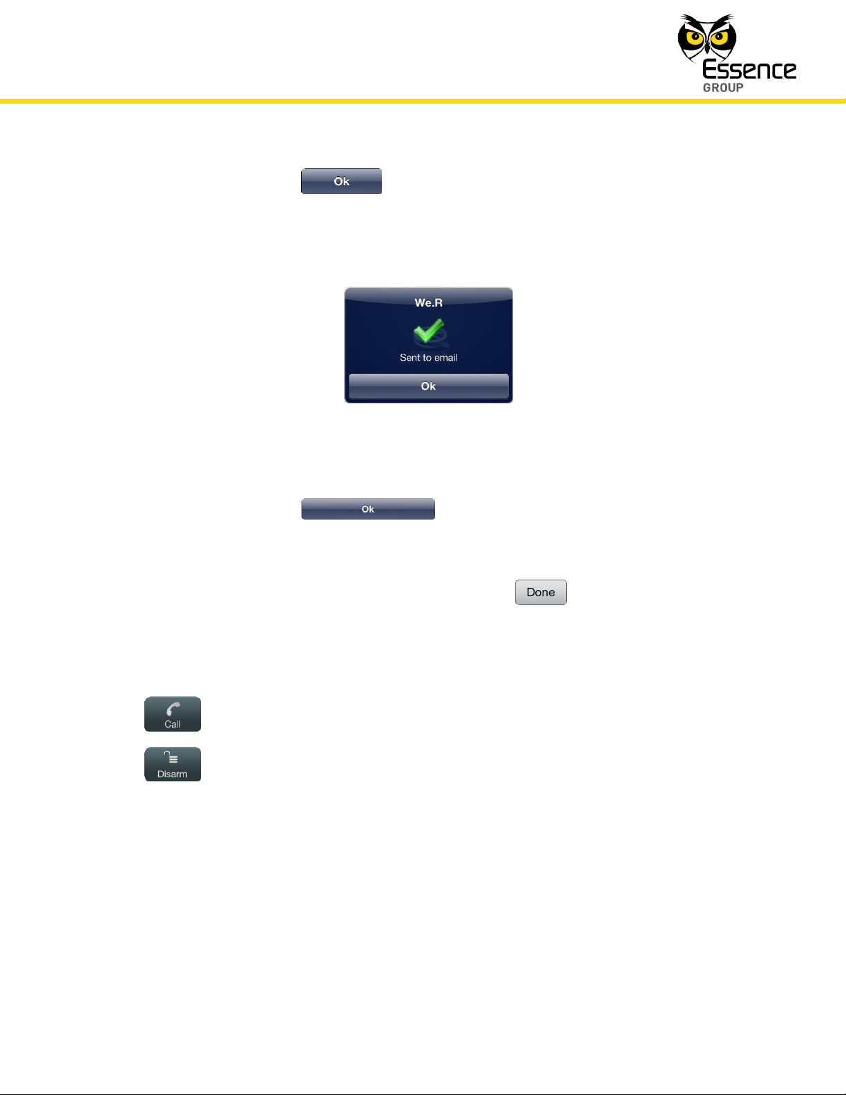
Tapping over the button will send the images via email to the User.
Upon completion, the following confirmation message window will pop-up:
Figure 179: Email Confirmation Message Window
Tapping over the button will conclude the send images by mail
operation and return the screen to the Camera Display screen (see above Figure
177).
In the Camera Display screen, tapping over the button will terminate the
Camera captured image presentation session and return the screen to the Panic
Alarm Screen (see above Figure 175).
– making emergency phone calls from the smartphone,
– disarming the system.
4.3. Monitoring the Premises
Utilizing the system’s installed camera(s), the We.R™ also allows its users to willfully monitor
(non-alarm triggered, initiated by the User) the premises, using the We.R™ Web Application or
the We.R™ Mobile Application.
Page 18
Administration of the We.R™ System
214
We.R™ System User Guide
This type of system usage is usually referred to as “Comfort Video”.
4.3.1. Monitoring with the We.R
™
Web Application
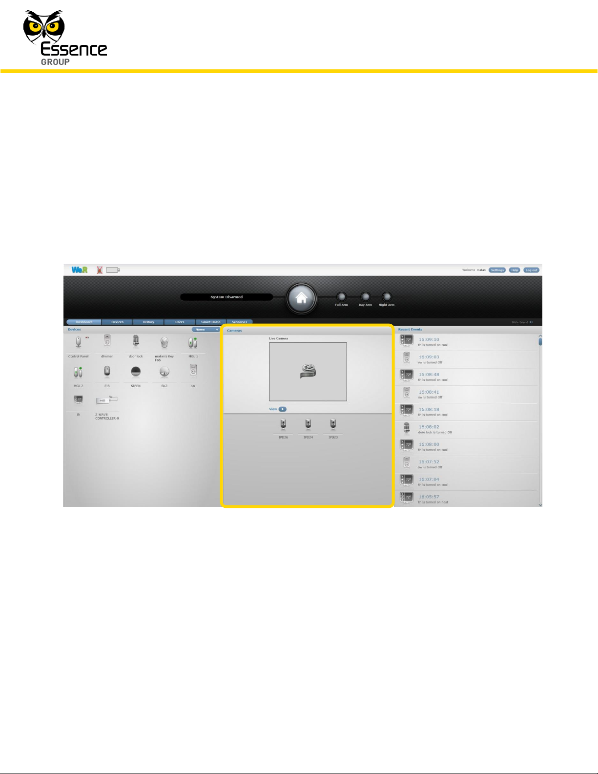
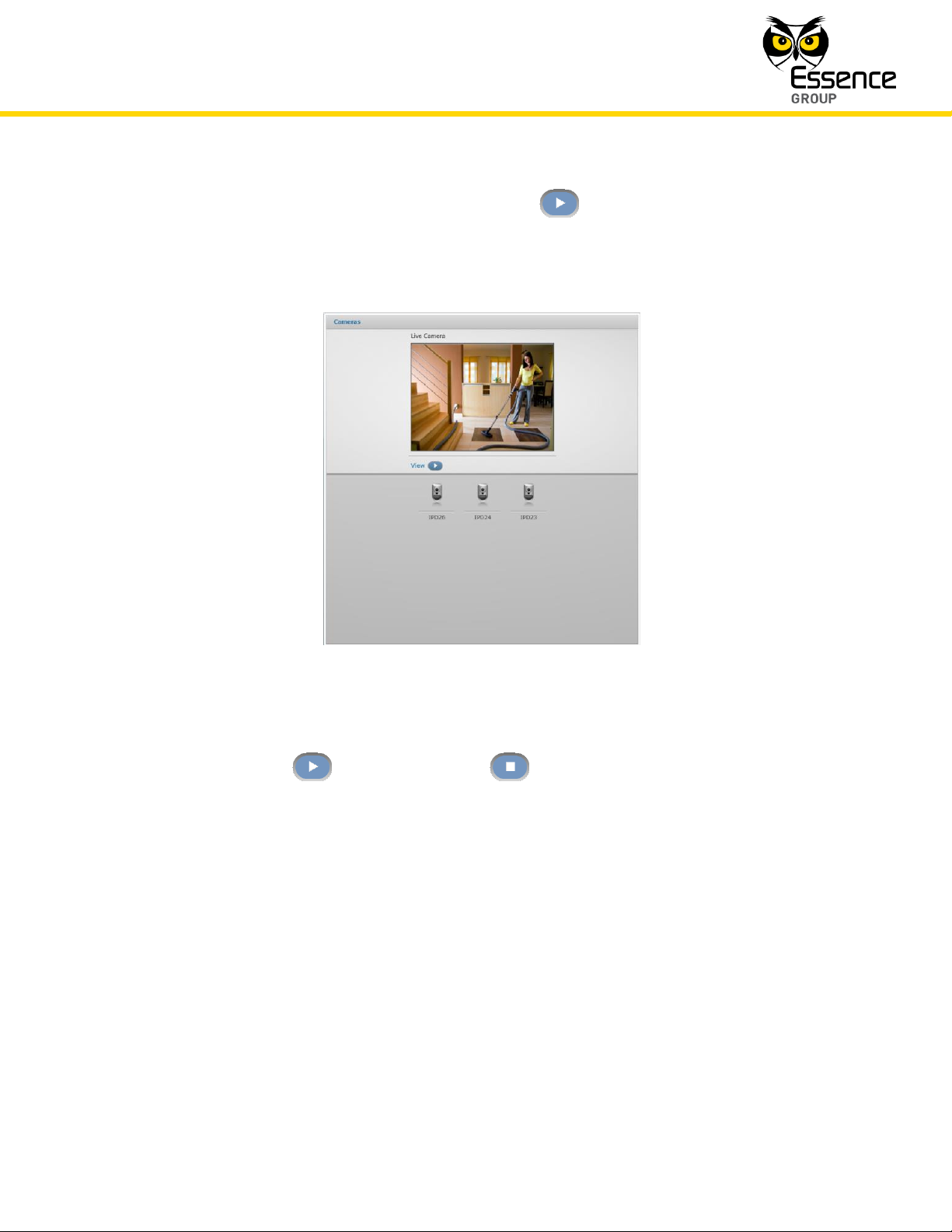
The center pan of the main screen (the Dashboard) data zone provides the means for comfort
video:
Figure 180: The Dashboard’s Camera Presentation
The bottom half of the center pane presents all system available cameras, out of which the
desired camera need to be selected by clicking once over its icon.
Upon selection, the system activates this camera and sends the images captured for viewing
within the frame at the top half of this pane (see Figure 181 below).
Page 19
Administration of the We.R™ System
We.R™ System User Guide
215
To see these images in video-like mode, click over the button. It will run the images for
about 40 seconds, in sequential mode, providing realistic monitoring of the premises.
Figure 181: Camera’s Captured Images Presentation
Once clicked upon, the button turns into a button allowing the User to halt the
presentation.
4.3.2. Monitoring with the We.R
™
Mobile Application
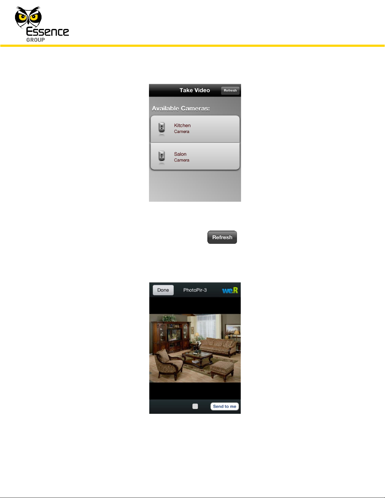
Similar to the We.R™ Web Application, the Video Tab/screen of the We.R™ Mobile Application
allows comfort view of the environment where the camera is installed.
Tapping over the Video Tab will switch the display to the Take Video screen (see Figure 182
below). This screen displays all cameras included in the system and the desired camera should
be selected out of this list.
Page 20
Administration of the We.R™ System
216
We.R™ System User Guide
Figure 182: The Take Video Screen
To refresh the Available Cameras list – tap over the button.
Tapping over one of the cameras in the list selects the camera and switches the screen into a
camera display screen presenting the view in front of the camera:
Figure 183: Comfort View of Camera
Page 21
Administration of the We.R™ System
We.R™ System User Guide
217
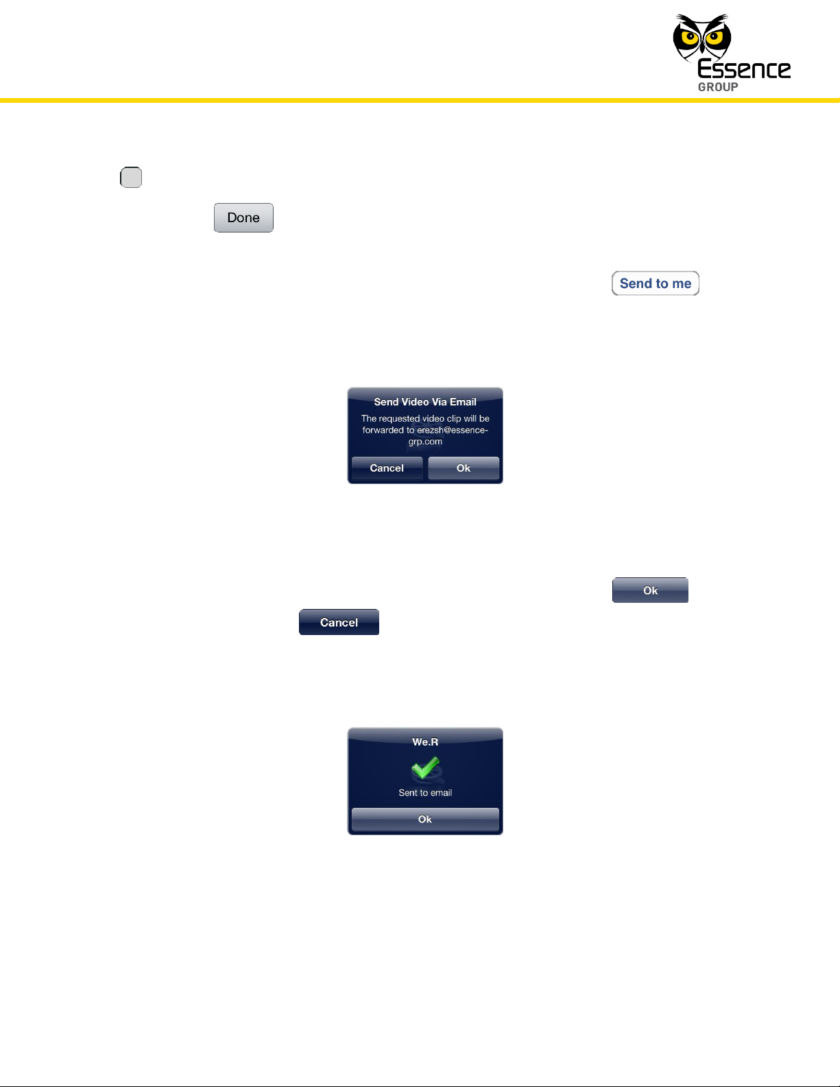
The button at the bottom of this screen is the Play/Pause switch.
Tapping over the button will terminate the comfort video session.
The images presented by the comfort view may be sent to the email address provided during
the We.R™ Mobile Application Registration procedure by clicking over the button.
Confirmation window will pop-up:
Figure 184: Confirmation of Image Transfer
Confirmation for sending the images via email is done by tapping over the button or
canceled by tapping over the button.
Success of the image transfer is acknowledged by the following message window:
Figure 185: Acknowledgement of Image Transfer
Page 22
Administration of the We.R™ System
218
We.R™ System User Guide
Note: Managing Users is possible only through the We.R™ Web Application
and by Master User only.
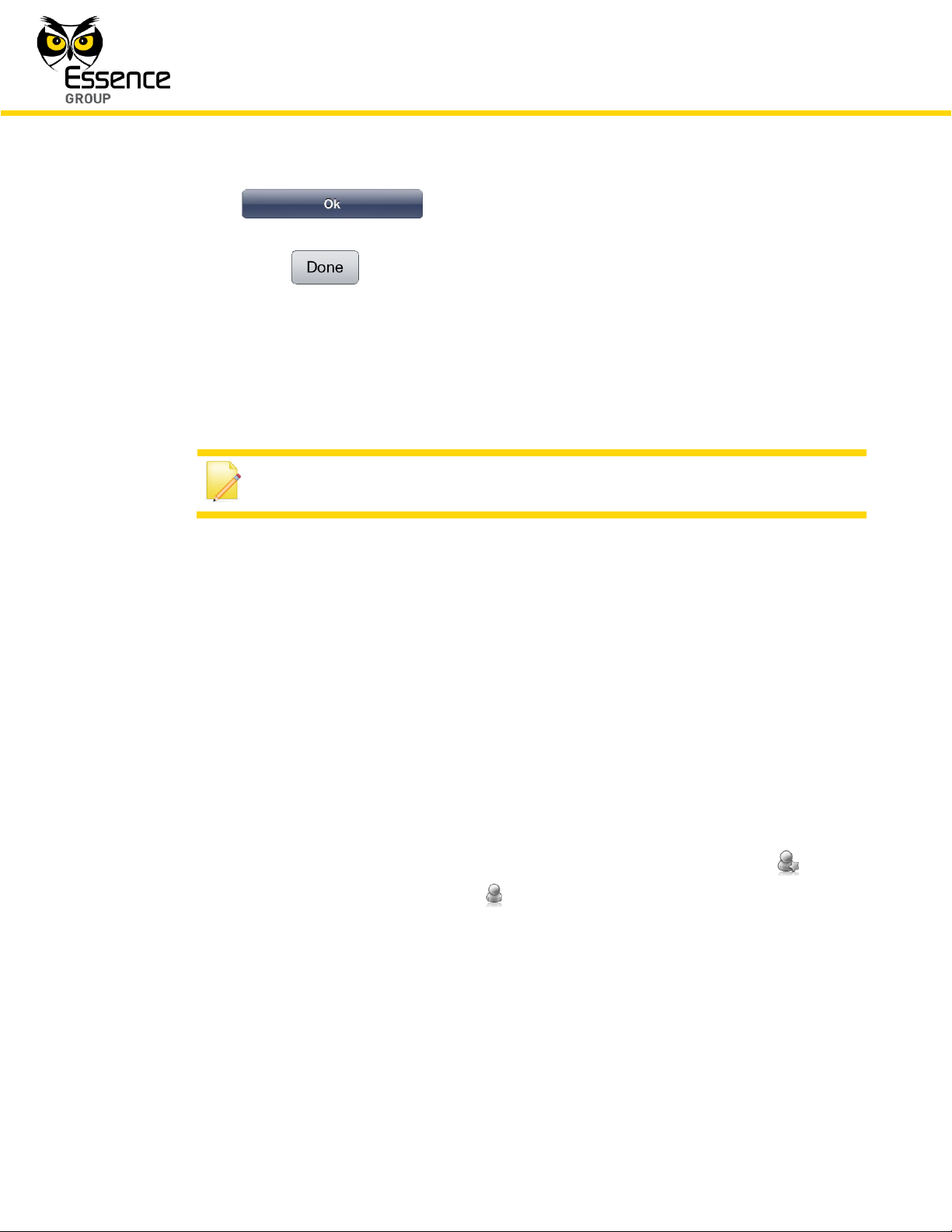
Tapping over the button will terminate the email process and return the
We.R™ Mobile Application to the Comfort View of Camera screen (see above Figure 183)
where tapping over the button will terminate the comfort video session and return the
display to the Home Status (Main) screen.
4.4. Managing Users
The We.R™ system requires definition of the Users allowed to control and use its operation.
For this purpose, Users need to be profiled and their data and types of control devices need to
be carefully defined in the system.
4.4.1. Profiling Users
Prior to adding a new User (or editing its setup) into the We.R™ system, an analysis of the
User’s requirements must be done to determine the reasons of its participation in the system
control and usage.
This process is called – Profiling Users.
1. The User need to be defined as either Master User (indicated by the system with icon) or
standard User (indicated by the system with icon).
The following considerations need to be applied:
a) Unlike a Standard User, a Master User may modify the system configuration
data, system Users’ data, delete/add Device/User, etc.
b) Up to two (2) Master Users may be defined in a single system.
Page 23
Administration of the We.R™ System
We.R™ System User Guide
219
c) Maximum total of 32 Users are supported by a single system (the two Masters
included).
2. Is the User going to use a Remote Control Unit (Key Fob) or a Tag to activate the system?
3. Does this User has a smartphone and is he going to use the We.R
™
Mobile Application?
4. What language does this User need for his notifications and push-messages?
Also, there is a need to prepare password and User Code for this User.
4.4.2. Adding Users
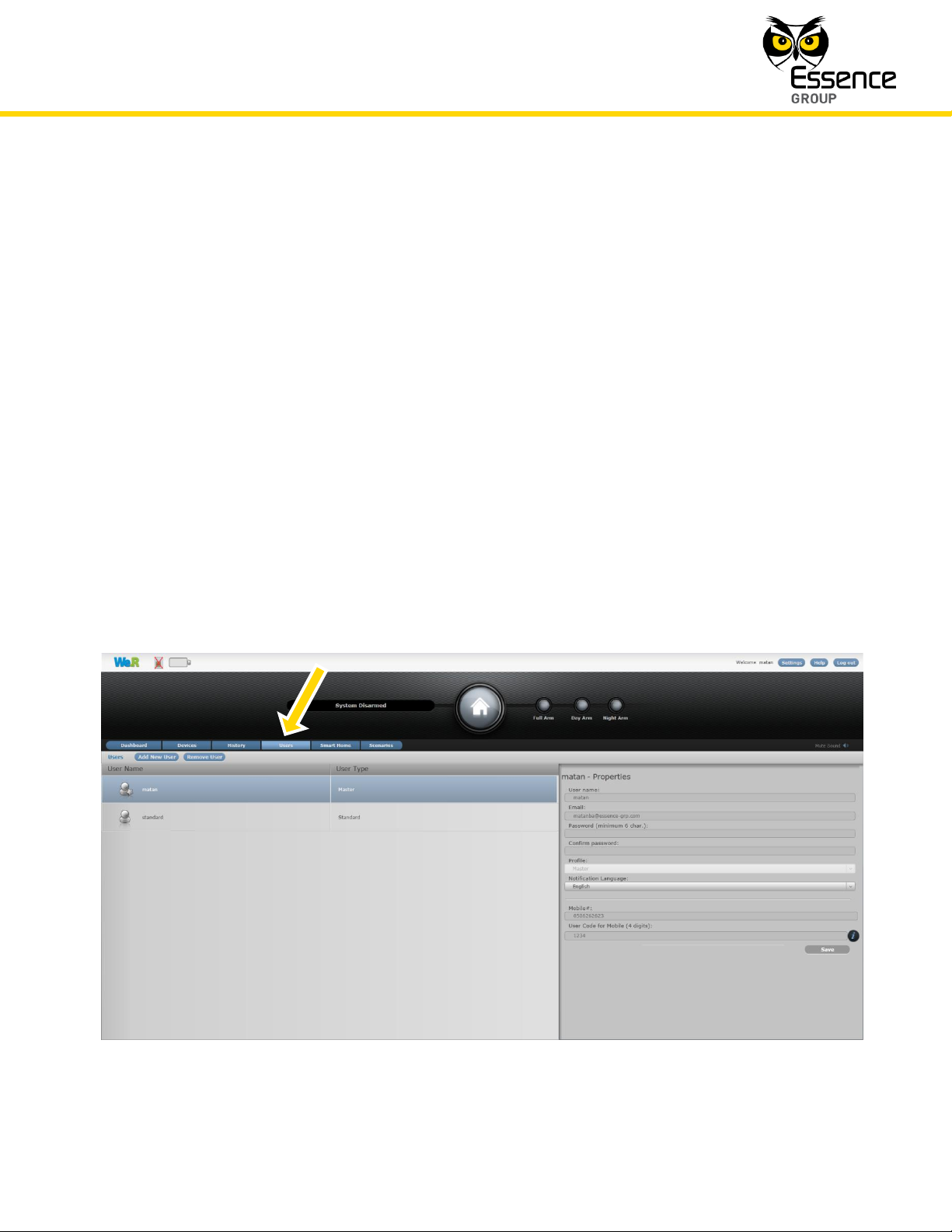
There are two panes in the Users page:
The left (overview) pane provides the User name and type (Master/Standard).
The right (details) pane provides all required data of the highlighted User line-item in the
left pane.
Figure 186: The We.R™ Web Application Users Page
Page 24
Administration of the We.R™ System
220
We.R™ System User Guide
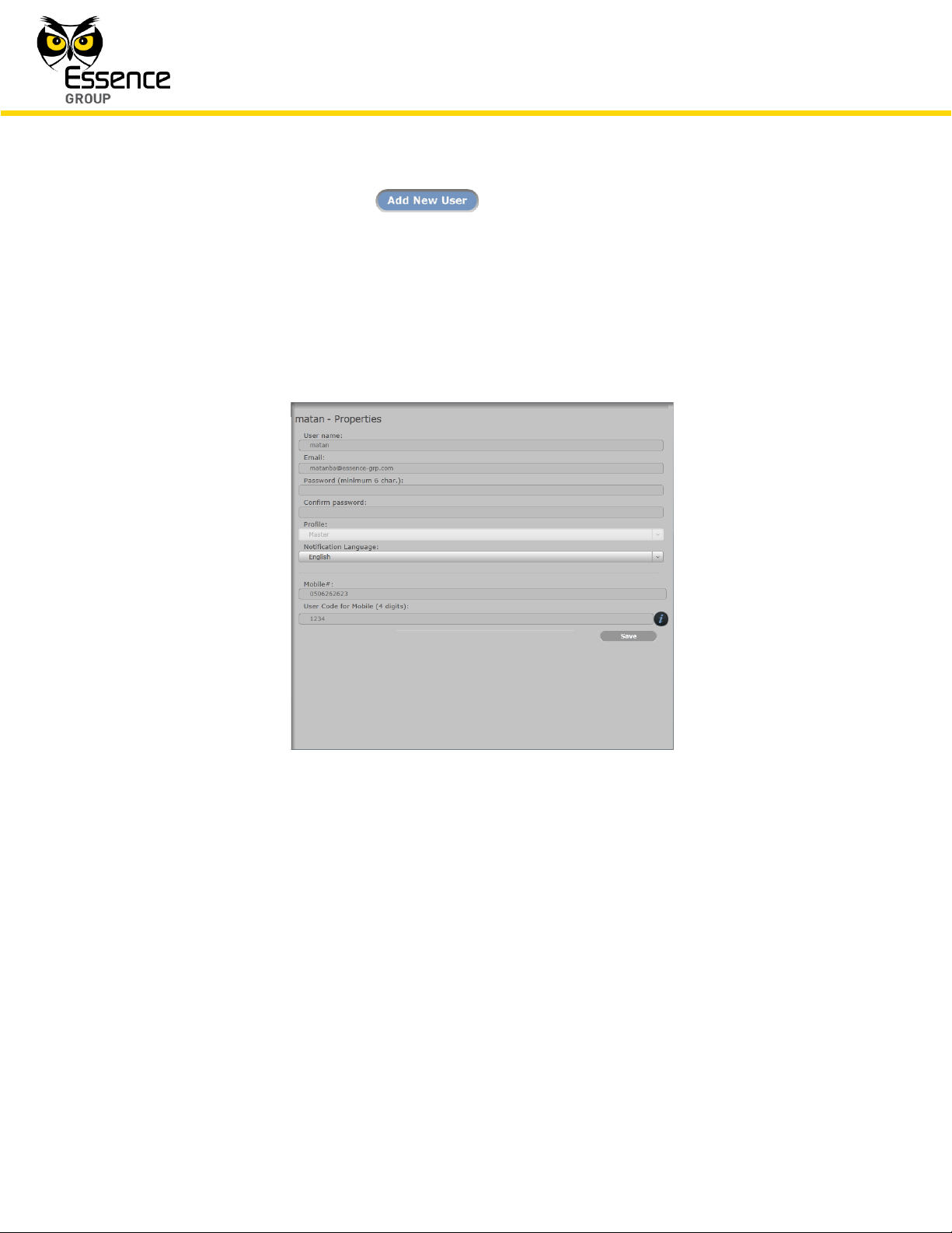
To add a new User, click over the button.
A new empty row will open in the left pane while its empty data fields – in the right pane.
Type-in the User’s data as follows:
The User name.
The User Email address (for notifications).
Figure 187: The Users Page Data Pane
The User Password (minimum of six alpha-numeric characters, case sensitive).
This password needs to be re-typed in the next row for confirmation.
The User Profile – select Standard or Master.
The Notification Language – select from the list of supported languages.
The User cellular phone number (international format, digits only).
The User Code (four digits) – for the Mobile Application.
Page 25
Administration of the We.R™ System
We.R™ System User Guide
221
Note: Assigning Remote Control Unit (Key Fob) or a Tag to this User is
done via the Devices page (see paragraph 4.5. below).
Once all the above data fields have been filled; click over the button to store the new
data into the system configuration files. The new empty row opened on the left pane will
display the User name and type once the new User data is accepted by the system.
4.4.3. Removing Users
Users may be removed from the system (by Master User only) by highlighting the specific User
line-item (row) in the left pane of the Users page (clicking over it), and then clicking over the
button.
Once the change is accepted by the system, the User’s row on the left pane will be deleted.
4.4.4. Editing Users
Standard Users may partially edit their data (right pane fields).
Such editing may be done on the following fields only:
User name
User’s email address
User’s mobile number
User’s Code
Standard Users may also change their password by marking the check-box and typing-in the
new password (twice).
Other fields are restricted for editing by Master Users only.
Once any of the data fields have been changed; click over the button to store the
new data into the system configuration files.
Page 26
Administration of the We.R™ System
222
We.R™ System User Guide
Note: Managing Devices is possible only with the We.R™ Web Application.
Note: Adding Devices is possible only by a Master User utilizing the We.R™
Web Application.
4.5. Managing Devices
The We.R™ system requires detailed definition of the Devices included in the system.
4.5.1. Adding New Devices
New Devices may be added (up to the system’s limitation, see Table 5 on page 194), to the
system at any time following its initial installation.
The process of adding a new Device is detailed, for each Device type, in paragraph 3.
Installation of the We.R™ System above, but, could be generally described as follows:
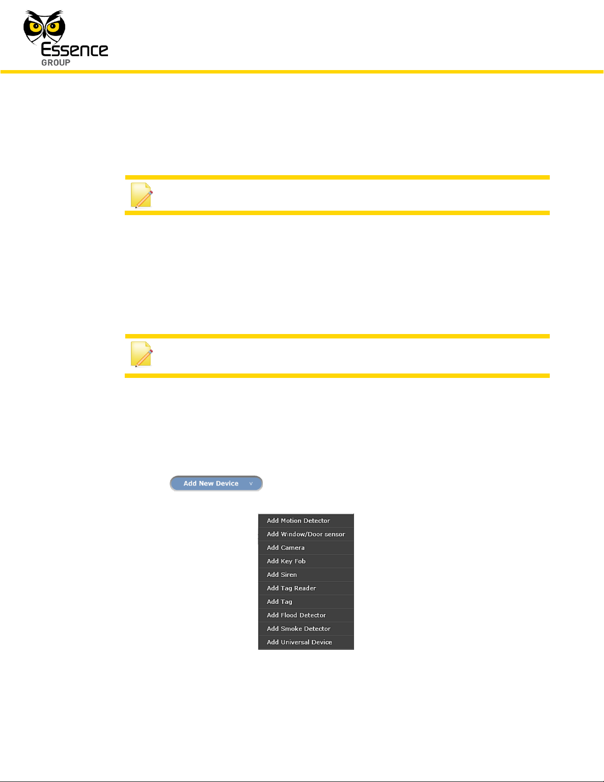
1. Clicking over the button opens a roll-down selection menu:
Figure 188: The Devices Selection Roll-down Menu
Page 27
Administration of the We.R™ System
We.R™ System User Guide
223
Note: In case the installation of the batteries could not be accomplished
within the three (3) minutes period, it is possible to restart the process.
2. The Device to be installed should be selected out of the menu list.
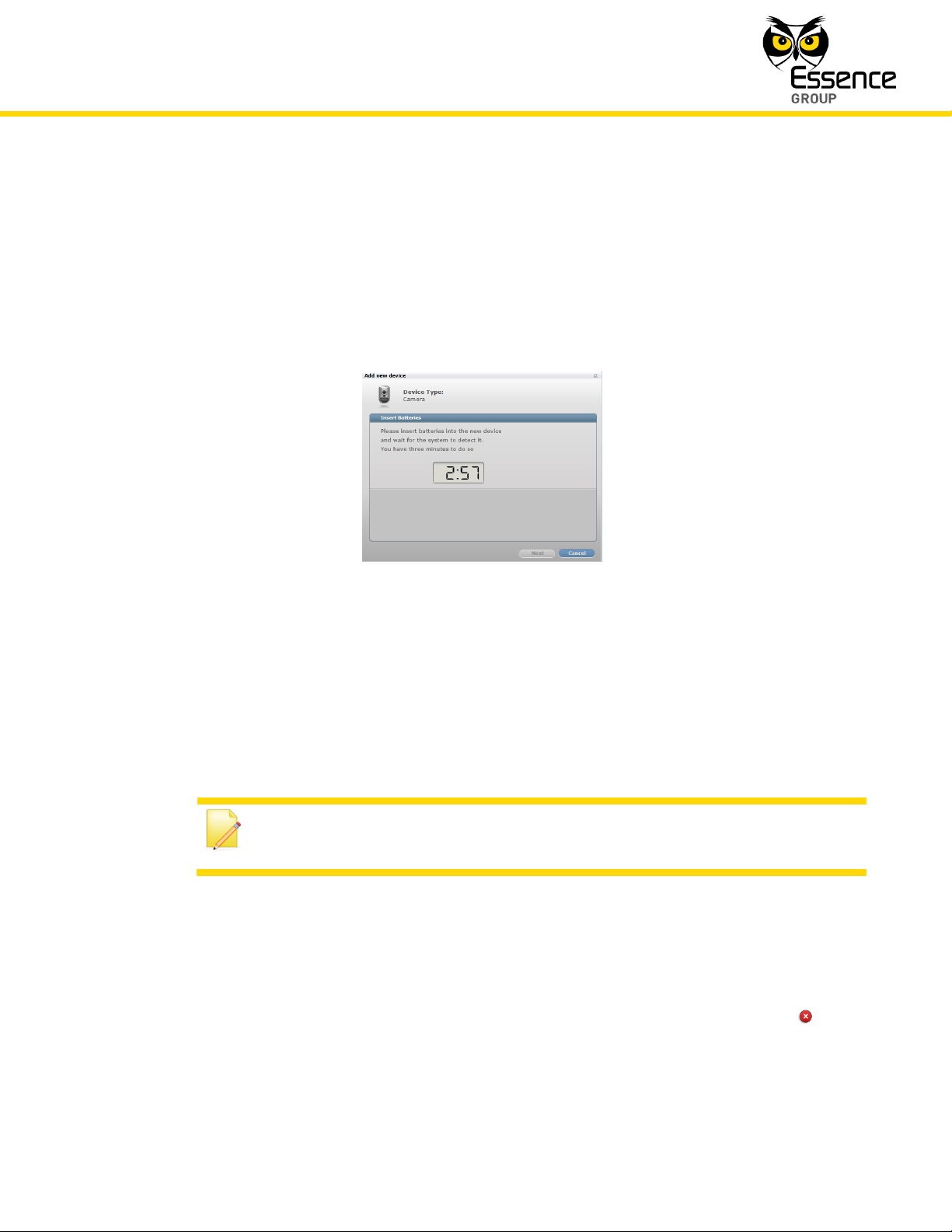
3. Once selected, the Add New Device window will pop-up and its timer will start running.
4. Use this window’s title to verify that the Device Type is the type selected from the roll-down
menu.
Figure 189: Add New Device Timer Window
5. The down-counter provides a time-frame of three (3) minutes within which the batteries
should be installed to power-up the Device.
6. The batteries insertion triggers a pairing process in which the Device communicates with
the CCU to inform it of its presence and the CCU add it to its peripherals’ inventory.
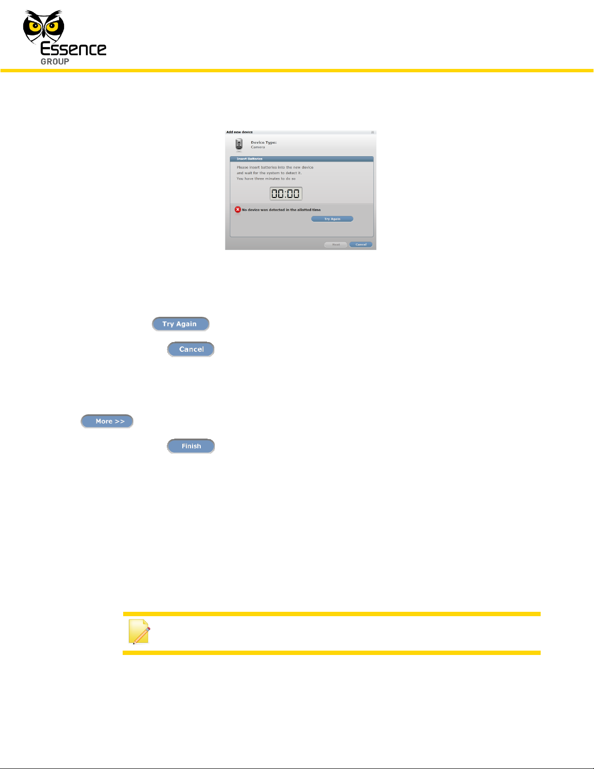
7. If the CCU did not detect the new Device within this time-frame, the following error ( )
message will appear within the Add New Device window:
Page 28
Administration of the We.R™ System
224
We.R™ System User Guide
Note: Removing Devices is possible only by a Master User and with the
We.R™ Web Application.
Figure 190: Add New Device Timeout Error Message
Click over the button to re-initiate the Add New Device process.
Clicking over the button will terminate the Add New Device process.
8. If the new Device was properly detected by the CCU, the counter will freeze and a Device
Properties sub-window will appear where the Device’s system name/location needs to be
typed-in as well as other features’ data (see paragraph 4.5.3 below) upon clicking over the
button.
9. Clicking over the button will end the Add New Device process.
The new device is added with its default operational details (i.e. Name/Location, arming
scenarios, etc.). These details might be edited, during the Add Device procedure or later on, as
described in paragraph 4.5.3 below.
4.5.2. Removing Devices
Page 29
Administration of the We.R™ System
We.R™ System User Guide
225
Note: Editing Devices’ properties is possible only by a Master User and with
the We.R™ Web Application.
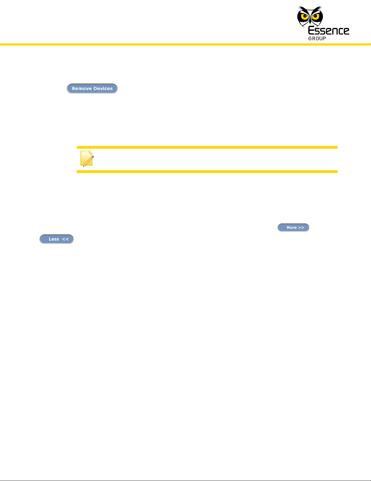
A Device may be removed by selecting its row in the left pane of the Devices page and clicking
over the button.
4.5.3. Editing Devices’ Properties
The We.R™ Web Application also enables editing of Devices already installed.
The editable data include the Device’s Name/Location as well as the Devices’ operational data
(Arming/Disarming Scenarios and special features).
Fields for such operational data are revealed/covered upon clicking over the /
button.
These fields might include:
Arming scenarios – to define if the Device will be included in the Day and/or Night
arming scenarios.
Arming Scenarios – what would the Device trigger (detection response) in case armed.
Non-armed Scenarios – some devices might also be functional even if not armed (i.e.
the Door/Window Magnetic Sensor may chime upon detection even if not armed to
inform the User of entries to the premises) and this data fields define such
functionalities.
Special features – if the Device has other data to be considered for proper system
operation (i.e. the Wireless Access Control Tag Reader can be installed indoor or
outdoor where indoor it is used for system arming like the Remote Control Unit and
outdoor – as a door bell), the operation data (scenarios) need to be defined.
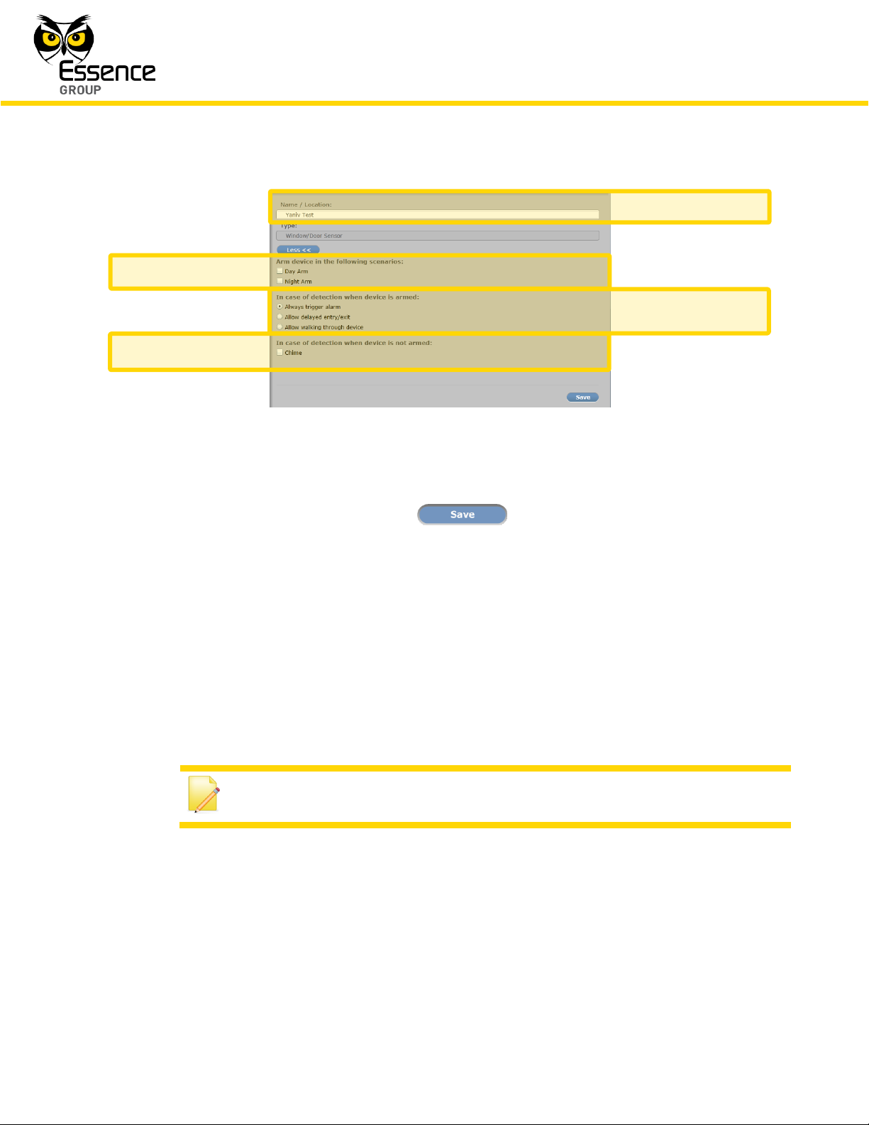
A right pane demonstrating all the above is the Door/Window Magnetic Sensor installation
pane:
Page 30
Administration of the We.R™ System
226
We.R™ System User Guide
Note: This configuration may be enabled, per device, for the security
devices (PIR/IPD/MGL).
Name/Location
Arm Scenarios
Disarm Scenarios
Special Features
Figure 191: Right Pane of Door/Window Magnetic Sensor
Once all Device definitions are provided, the button needs to be clicked upon to
store the data in the system.
4.5.4. Advanced Configurations of the We.R
™
Devices
4.5.4.1. Entry/Exit
This feature provides the owner with time gap to arm (or disarm) the system while entering (or
exiting) the premises without triggering an alarm.
Once the Entry/Exit feature is enabled:
A premises entry delay of 30 seconds will be triggered upon detection event, allowing
the User to disarm the system prior to triggering an alarm.
In case a Siren is installed in the system, the delay will be accompanied by short beeps
to notify the User about the delay.
Page 31

Administration of the We.R™ System
We.R™ System User Guide
227
Note: Also please refer to paragraph 4.5.4.2 below regarding more
complex installations combining multiple sensors.
Notes: The Walk-Through configuration may be enabled, per device, for the
security devices (PIR/IPD/MGL).
This feature will become operational only if another security device in the
system is configured as Entry/Exit.
Configuring a device as Walk-Through with no other device configured as
Entry/Exit is feasible, but will have no functional value in the system.
A single device may be defined as either Entry/Exit or Walk-Through.
In case the system was not disarmed within the 30 seconds delay period – an alarm
will be triggered and a burglary alarm flow will start (notifications, emails etc.)
A premises exit delay of 30 seconds will be triggered only once the system was armed
via a Tag Reader.
This delay allows the User to arm the system and leave the premises without triggering
an alarm on the way out.
The Tag Reader and Siren (if installed) will sound short beeps to notify the User of this
delay.
Common use of the Entry/Exit feature – usually enabled for a Magnetic Sensor (MGL) installed
on the main entrance door, or for a Motion Detector (PIR) or Camera (IPD) which installed in
the entrance.
4.5.4.2. Devices Allowing Walk-Through
This feature is provided for cases where a Camera (or Motion Detector) device is installed in
close proximity to a premises’ entry door equipped with a Magnetic Sensor and defined as
Entry/Exit, where such device might trigger an alarm within the delay period.
Page 32

Administration of the We.R™ System
228
We.R™ System User Guide
Notes: This feature may be enabled for Magnetic Sensor (MGL) only, and is
possible only when a Siren is installed as well.
Configuring a Magnetic Sensor as Chime with no Siren installed is feasible,
but will have no functional value in the system.
A Magnetic Sensor may be defined as Entry/Exit or Walk-Through and as
Chime simultaneously.
Once the Walk-Through feature is enabled:
Throughout the 30 seconds delay period of an Entry/Exit configured device, the device
configured as Walk-Through will trigger an alarm only if triggered before the device
defined as Entry/Exit.
The detection of the Walk-Through device will be logged in the Recent Events report.
In case of Entry/Exit – if the system is not disarmed within the 30 seconds delay period,
the Walk-Through device will trigger an alarm.
In case a Walk-Through device is directly triggered (the Entry/Exit device was not
triggered first) – an alarm will immediately be triggered.
In case the Walk-Through devices is a Camera (IPD) and was triggered following an
Entry/Exit device and the system was disarmed – a security image capturing event will
be logged, however, no security clip will be available for view since eventually no alarm
was triggered.
Common use of the Walk-Through feature – if a Magnetic Sensor (MGL) is installed on the
main-entry door and defined as Entry/Exit, and a Camera (IPD) or Motion Detector (PIR) is
installed in front of the door or in close proximity; the Camera or Motion Detector should be
configured as a Walk-Through device.
4.5.4.3. Chime
This feature provides audible warning for a door being opened when the system is disarmed.
Page 33

Administration of the We.R™ System
We.R™ System User Guide
229
Once the Chime feature is enabled:
Whenever the system is disarmed, the Siren will emit a bell-like sound whenever the
Magnetic Sensor is opened.
Common use of the Chime feature – if a Magnetic
For Users who likes to get an audible warning upon a door being opened (i.e. in small
shops/offices).
Page 34

Administration of the We.R™ System
230
We.R™ System User Guide
This page was intentionally left blank
Page 35

Maintenance of the We.R™ System
We.R™ System User Guide
231
5. Maintenance of the We.R
The We.R™ system is almost maintenance-free; the only maintenance-oriented activities
required for its continuous operation are:
1. Replacing Batteries – an indication of the need for batteries replacement is provided by
both the We.R™ Web Application and the We.R™ Mobile Application utilizing their different
status displays.
2. Cleaning the Smoke Detector’s filter – on a monthly basis, to remove dust that might block
the path to the sensor.
Other than that, there is no other maintenance activity required for proper operation of the
We.R™ system.
™
System
5.1. Replacing Batteries
5.1.1. Replacing the Central Control Unit Backup Battery
For its operation, the Central Control Unit (CCU) needs a special 3.7VDC, 1400
Polymer rechargeable battery (Essence P/N MCBT05001) and a Power Adapter.
5.1.1.1. Removing the Old Backup Battery
To remove an old battery from the CCU:
1. Remove the Power Supply from the mains socket and disconnect its cable and mini-USB™
connector from the CCU.
5. Remove the CCU’s back cover, to reveal the battery’s and SIM-card compartment, by
inserting a finger nail between the cover and its frame and lift it as demonstrated in Figure
192 above.
6. Remove the battery by lifting its top-facing edge (note that a special bay is provided for this
purpose) and pulling the battery out of the battery cavity, as demonstrated in Figure 193
below.
Lithium
mAh
Page 36

Maintenance of the We.R™ System
232
We.R™ System User Guide
Figure 192: Releasing the Back Cover
Figure 193: Removing the Battery
Page 37

Maintenance of the We.R™ System
We.R™ System User Guide
233
Note: Battery’s label should be facing up and the battery’s contacts should
be aiming towards the base of the CCU.
Notes: The green LED indicates that the CCU is properly active.
It takes approximately 5 minutes for the LED to turn green.
5.1.1.2. Installing a New Battery
1. Insert the new backup battery into the battery compartment, above the SIM-card, as
demonstrated in Figure 194 below:
Figure 194: Insertion of the Backup Battery
2. Return the battery cover back to place and click it firmly in.
3. Plug the Power Adapter's cable into the mini-USB
™
connector on the back of the CCU and
plug the adapter’s cube into the mains’ socket.
The LED on the front panel of the Central Control Unit should turn ON in orange color.
4. Place the CCU in its designated location and wait for the front panel LED to switch from
orange to green color.
Once the LED turns green – the system is up and running as before and there is no need for
any further action.
Page 38

Maintenance of the We.R™ System
234
We.R™ System User Guide
Note: Rattling sounds might be heard during the batteries’ replacement
process. Nothing to worry about – it is the tampering prevention
mechanism.
5.1.2. Replacing the Camera (IPD) Batteries
For its operation, the Camera needs three (3) 1.5V AA-size Alkaline batteries (not supplied with
the Camera).
5.1.2.1. Removing the Old Batteries
Figure 195: Dismounting the Camera
Page 39

Maintenance of the We.R™ System
We.R™ System User Guide
235
To replace the old batteries of the Camera, first, there is a need to dismount it from its install
site (the wall).
1. To dismount the Camera, press the wall mounting base's tab at the bottom of the Camera
and slide it downwards simultaneously as demonstrated in Figure 195 above.
2. Release the batteries (inner) cover by pressing against the inner batteries’ cover tab and
Lift/twist of the cover up as demonstrated in Figure 196 below:
Figure 196: Releasing the Camera Inner Batteries’ Cover
3. Remove the batteries by pressing them slightly towards the negative (–) pole (towards the
top end of the Camera) and extracting them out, one at a time.
5.1.2.2. Installing New Batteries
1. Install the new batteries as demonstrated in Figure 197 below (the positive () poles aiming
towards the lens):
Figure 197: Inserting Batteries into the Camera
Page 40

Maintenance of the We.R™ System
236
We.R™ System User Guide
Note: There is no need to perform “Add Device” process following batteries
replacement since the Camera is already defined in the We.R™ system.
But, replacing the batteries will trigger the Walk Test Mode (see
paragraph 3.6.4.1 above) to ensure proper battery replacement.
Note: Rattling sounds might be heard during the batteries replacement
process. Nothing to worry about – it is the tampering prevention
mechanism.
2. Close the inner batteries’ cover and click it back to place.
3. Return the Camera back onto its mounting base.
The insertion of batteries into the Camera triggers a bonding process in which the Camera
communicates with the CCU to re-instate it into the CCU peripherals’ inventory.
5.1.3. Replacing the Motion Detector (PIR) Batteries
For its operation, the Motion Detector needs two (2) 1.5V AA-size Alkaline batteries.
5.1.3.1. Removing the Old Batteries
To replace the old batteries of the Motion Detector, first, there is a need to dismount it from its
install site (the wall).
1. To dismount the Motion Detector, press the wall mounting base's tab at the bottom of the
Motion Detector and slide it downwards simultaneously as demonstrated in Figure 198
below.
Page 41

Maintenance of the We.R™ System
We.R™ System User Guide
237
Figure 198: Dismounting the Motion Detector
2. The batteries’ (back) cover is the mounting base of the Motion Detector therefore
dismounting it also reveals the Motion Detector batteries compartment.
3. Remove the batteries by pressing them slightly towards the negative (–) pole (towards the
bottom end of the Motion Detector) and extracting them out, one at a time.
5.1.3.2. Installing New Batteries
1. Install the new batteries as demonstrated in Figure 199 below (the positive () poles aiming
towards the top end of the device):
Page 42

Maintenance of the We.R™ System
238
We.R™ System User Guide
Note: There is no need to perform “Add Device” process following batteries
replacement since the Motion Detector is already defined in the We.R™
system. But, replacing the batteries will trigger the Walk Test Mode (see
paragraph 3.7.4.1 above) to ensure proper battery replacement.
Figure 199: Inserting Batteries into the Motion Detector
2. Return the Motion Detector back onto its mounting base.
The insertion of batteries into the Motion Detector triggers a bonding process in which the
Motion Detector communicates with the CCU to re-instate it into the CCU peripherals’
inventory.
5.1.4. Replacing the Magnetic Sensor (MGL) Battery
For its operation, the MGL needs single 1.5V AA-size Alkaline battery.
5.1.4.1. Removing the Old Batteries
There is a need to dismount the Magnetic Sensor (Transmitter unit only) to allow replacement
of the battery. To dismount the Magnetic Sensor:
Page 43

Maintenance of the We.R™ System
We.R™ System User Guide
239
1. Insert a flat screw driver (or coin) into one of the edge slots as demonstrated in Figure 200
below.
2. Twist it to raise the cover (body) edge.
3. Pull the body strait out of the base’s shoulders.
Figure 200: Dismounting the Magnetic Sensor’s Transmitter
5.1.4.2. Removing the Old Battery
Once opened, the Magnetic Sensor’s battery is free to be removed out of the case.
Apply slight pressure on the battery towards the negative (–) pole to ease the release of the
battery.
5.1.4.3. Installing a New Battery
1. The battery should be installed, as demonstrated in Figure 201 below (the positive () pole
as marked within the device body).
2. Verify battery polarity match to marking within the unit body.
3. Return the cover onto the base and click it in.
Page 44

Maintenance of the We.R™ System
240
We.R™ System User Guide
Note: There is no need to perform “Add Device” process following battery
replacement since the Magnetic Sensor is already defined in the We.R™
system.
Figure 201: Inserting a Battery into the Transmitter Unit
The insertion of battery into the Magnetic Sensor triggers a bonding process in which the
Magnetic Sensor communicates with the CCU to re-instate it into the CCU peripherals’
inventory.
5.1.5. Replacing the Indoor Siren (SRN) Batteries
For its operation, the Siren needs four (4) 1.5V AA-size Alkaline batteries.
5.1.5.1. Removing the Old Batteries
To replace the old batteries of the Siren, first, there is a need to dismount it from its install site
(the wall).
1. To dismount the Siren, press the wall mounting base's tab at the bottom of the Siren and
slide the body upwards as demonstrated in Figure 202 below.
Page 45

Maintenance of the We.R™ System
We.R™ System User Guide
241
Figure 202: Dismounting the Siren
2. The mounting base (back cover) of the Siren is the batteries’ cover as well and, therefore,
dismounting the Siren also reveals its batteries compartment.
3. Remove the batteries by pressing them slightly towards the negative (–) pole (note that
each battery is in opposite direction to the adjoining battery) and extracting them out, one
at a time.
5.1.5.2. Installing New Batteries
Prior to the installation of the new batteries in the Siren, it is advised to discharge its electronic
circuit from accumulated static charges.
Page 46

Maintenance of the We.R™ System
242
We.R™ System User Guide
Note: Each battery is in opposite direction to the adjoining battery and the
correct polarity is engraved onto the bottom of the batteries’ compartment.
To discharge the Siren, insert the back cover’s tab into the niche at the bottom of the batteries’
compartment as demonstrated in Figure 203 below.
Figure 203: Discharging the Siren’s Electronic Circuit
1. Install the new batteries as demonstrated in Figure 204 below.
2. Return the Siren back onto its mounting base.
Page 47

Maintenance of the We.R™ System
We.R™ System User Guide
243
Note: There is no need to perform “Add Device” process following batteries
replacement since the Siren is already defined in the We.R™ system.
Figure 204: Inserting Batteries into the Siren
The insertion of batteries into the Siren triggers a bonding process in which the Siren
communicates with the CCU to re-instate it into the CCU peripherals’ inventory.
5.1.6. Replacing the Remote Control Unit (KF) Battery
For its operation, the Remote Control Unit (KF) needs single 3V CR2450 lithium (coin) battery.
Page 48

Maintenance of the We.R™ System
244
We.R™ System User Guide
Note: It is advised to release stored charges within the KF electronic circuit
by clicking on any of the front panel keys a few times before the installation
of the new battery.
5.1.6.1. Removing the Old Battery
1. Release the cover of the KF battery compartment by inserting a coin into the slot and
turning the cover a quarter of a circle (90o) counter-clockwise until the two small bumps
face each other as demonstrated in Figure 205 below.
Figure 205: Releasing the KF’s Battery Cover
2. Remove the cover by tapping it upside-down on your palm.
3. Remove the old battery.
5.1.6.2. Installing a New battery
1. Insert the new battery into the KF’s cavity with its positive () pole facing out/up.
2. Seal the cover by turning it a quarter of a circle (90
o
) clockwise.
Page 49

Maintenance of the We.R™ System
We.R™ System User Guide
245
Note: There is no need to perform “Add Device” process following battery
replacement since the KF is already defined in the We.R™ system.
Figure 206: Inserting the New KF’s Battery
5.1.7. Replacing the Tag Reader (TR5) Batteries
For its operation, the Tag Reader needs three (3) 1.5V AA-size Alkaline batteries.
5.1.7.1. Removing the Old Batteries
To replace the old batteries of the Tag Reader, first, there is a need to dismount it from its
install site (the wall).
1. To dismount the Tag Reader, press the wall mounting base's tab at the bottom of the Tag
Reader and slide the body upwards as demonstrated in Figure 207 below.
2. The mounting base (back cover) of the Tag Reader is the batteries’ cover as well and,
therefore, dismounting the Tag Reader also reveals its batteries compartments (three off).
3. Remove the batteries by pressing them slightly towards the negative (–) pole and
extracting them out, one at a time.
Page 50

Maintenance of the We.R™ System
246
We.R™ System User Guide
Note: The Tags are passive components and need no power source
(battery). Therefor there is no maintenance required for the Tags.
Figure 207: Dismounting the Tag Reader
5.1.7.2. Installing New Batteries
1. Install the new batteries as demonstrated in Figure 208 below. Note that the correct polarity
is engraved onto the bottom of each of the batteries’ compartment.
Page 51

Maintenance of the We.R™ System
We.R™ System User Guide
247
Note: There is no need to perform “Add Device” process following batteries
replacement since the Tag Reader is already defined in the We.R™ system.
Figure 208: Inserting Batteries into the Tag Reader
2. Return the Tag Reader back onto its mounting base.
The insertion of batteries into the Tag Reader triggers a bonding process in which the Tag
Reader communicates with the CCU to re-instate it into the CCU peripherals’ inventory.
5.1.8. Replacing the Flood Detector (FL) Battery
For its operation, the Flood Detector needs single 1.5V AA-size Alkaline battery.
There is a need to dismount the Flood Detector (Transmitter unit only) to allow replacement of
the battery. To dismount the Flood Detector:
1. Insert a flat screw driver (or coin) into one of the edge slots as demonstrated in Figure 209
below.
2. Twist it to raise the cover (body) edge.
3. Pull the body strait out of the base’s shoulders.
Page 52

Maintenance of the We.R™ System
248
We.R™ System User Guide
Figure 209: Dismounting the Flood Detector’s Transmitter
5.1.8.1. Removing the Old Battery
Once opened, the Flood Detector’s battery is free to be removed out of the case.
Apply slight pressure on the battery towards the negative (–) pole to ease the release of the
battery.
5.1.8.2. Installing a New Battery
1. The battery should be installed, as demonstrated in Figure 210 below (the positive () pole
as marked within the device body):
Figure 210: Inserting a Battery into the Transmitter Unit
Page 53

Maintenance of the We.R™ System
We.R™ System User Guide
249
Note: There is no need to perform “Add Device” process following battery
replacement since the Flood Detector is already defined in the We.R™
system.
Note: The Smoke Detector is equipped with a special mechanism designed
to prevent insertion of the Detector’s body into its base without the
batteries properly installed as well as provide omni-directional assembly
and ensure secured assembly.
2. Verify battery polarity match to marking within the unit body.
3. Return the cover onto the base and click it in.
The insertion of battery into the Flood Detector triggers a bonding process in which the Flood
Detector communicates with the CCU to re-instate it into the CCU peripherals’ inventory.
5.1.9. Replacing the Smoke Detector (SK2) Batteries
For its operation, the SK2 needs two (2) 1.5V AA-size Alkaline batteries.
There is a need to dismount the Smoke Detector to allow replacement of the batteries.
5.1.9.1. Dismounting the Smoke Detector
To dismount the Smoke Detector:
1. Hold the Smoke Detector’s body with three-four (3-4) fingers as demonstrated in Figure
211 below.
2. Twist it slightly in counter clockwise direction.
Page 54

Maintenance of the We.R™ System
250
We.R™ System User Guide
3. Pull the body strait out of the base.
Figure 211: Dismounting the Smoke Detector
5.1.9.2. Removing the Old Batteries
Remove the batteries by pressing them slightly towards the negative (–) pole and extract them
out, one at a time.
Page 55

Maintenance of the We.R™ System
We.R™ System User Guide
251
Note: There is no need to perform “Add Device” process following batteries
replacement since the Smoke Detector is already defined in the We.R™
system.
5.1.9.3. Installing New Batteries
1. Install the new batteries as demonstrated in Figure 212 below. Note that the correct polarity
is engraved onto the bottom of each of the batteries’ compartment.
Figure 212: Inserting Batteries into the Smoke Detector
2. Return the Smoke Detector back onto its mounting base.
The insertion of batteries into the Smoke Detector triggers a bonding process in which the
Smoke Detector communicates with the CCU to re-instate it into the CCU peripherals’
inventory.
5.1.10. Replacing the Universal Transmitter (UT) Battery
For its operation, the Universal Transmitter needs single 1.5V AA-size Alkaline battery.
Page 56

Maintenance of the We.R™ System
252
We.R™ System User Guide
5.1.10.1. Dismounting the Universal Transmitter
There is a need to dismount the Universal Transmitter (Transmitter unit only) to allow
replacement of the battery. To dismount the Universal Transmitter:
1. Insert a flat screw driver (or coin) into one of the edge slots as demonstrated in Figure 213
below.
2. Twist it to raise the cover (body) edge.
3. Pull the body strait out of the base’s shoulders.
Figure 213: Dismounting the Universal Transmitter’s Transmitter Unit
5.1.10.2. Removing the Old Battery
Once opened, the Universal Transmitter’s battery is free to be removed out of the case.
Apply slight pressure on the battery towards the negative (–) pole to ease the release of the
battery.
Page 57

Maintenance of the We.R™ System
We.R™ System User Guide
253
Note: There is no need to perform “Add Device” process following battery
replacement since the Universal Transmitter is already defined in the
We.R™ system.
5.1.10.3. Installing a New Battery
1. The battery should be installed, as demonstrated in Figure 214 below (the positive () pole
as marked within the device body):
Figure 214: Inserting a Battery into the Transmitter Unit
2. Verify battery polarity match to marking within the unit body.
3. Return the cover onto the base and click it in.
The insertion of battery into the Universal Transmitter triggers a bonding process in which the
Universal Transmitter communicates with the CCU to re-instate it into the CCU peripherals’
inventory.
Page 58

Maintenance of the We.R™ System
254
We.R™ System User Guide
Clean here
5.2. Cleaning the System Devices
The Smoke Detector’s sensor is protected from dust and other particles with a metal filter.
This filter accumulates dirt which must be removed periodically
Carefully remove any dust residing on the Smoke Detector's components applying special
attention to the openings of the detection chamber.
Figure 215: Cleaning the Smoke Detector
After cleaning, replace the batteries, and then test the smoke alarm to make sure it is
functioning properly.
Page 59

Security Aspects
We.R™ System User Guide
255
6. Security Aspects
6.1. Secured Communication between User and Application Server
Authentication:
Mobile authentication is performed via email, password and User Code for
the activation of the Mobile Application.
Password and User codes are encrypted on the mobile handset utilizing
SHA1 algorithm.
The encrypted value is calculated and sent as identifying credentials.
The server generates the encrypted value locally, based on stored user
details, and then authenticates the value by comparison.
6.2. Communication Security between CCU and Application Server
Data is encrypted and secured using SSL between the web/smartphone applications
and the ECS.
Data is authenticated using a proprietary protocol.
6.3. Communication Security between CCU and sensors
All communication between the Central Control Unit and the sensors are encrypted
with an AES algorithm, 128 bit and varying keys.
Page 60

Security Aspects
256
We.R™ System User Guide
This page was intentionally left blank
Page 61

Security Aspects
We.R™ System User Guide
257
Term
Description
3G
3G is a short for 3rd Generation.
This is a term used to represent the 3rd generation of mobile telecommunications
technology.
Also called Tri-Band 3G. This is a set of standards used for mobile devices and
mobile telecommunication services and networks that comply with the
International Mobile Telecommunications-2000 (IMT-2000) specifications issued
and maintained by the International Telecommunication Union.
AES
Advanced Encryption Standard.
A specification for the encryption of electronic data in a symmetric-key
encryption format based on a design principle known as a substitutionpermutation network, and is fast in both software and hardware.
API
Application Programming Interface.
A specification of how some software components should interact with each
other.
In practice in most of the cases an API is a library that usually includes
specification for routines, data structures, object classes, and variables.
APN
Access Point Name.
The name of a gateway between a GPRS (or 3G, etc.) mobile network and
another computer network, frequently the public Internet.
APNS
Apple Push Notification Service.
A service created by Apple Inc.
It uses push technology through a constantly open IP connection to forward
notifications from the servers of third party applications to the Apple devices;
such notifications may include badges, sounds or custom text alerts.
ASMX
ASP.NET Web-services’ Source file for web application framework.
ASP
Active Server Pages.
Microsoft's first server-side script engine for dynamically generated web pages.
Association
A Z-Wave® Term.
Linking together two nodes (units) so that one of them will send information to
the other automatically when a value or level changes.
The sending node is the source node and the node receiving the information is
the target node.
ATP
Automatic Test Plan
Appendix A Terms, Abbreviations and Acronyms
Page 62

Terms, Abbreviations and Acronyms
258
We.R™ System User Guide
Term
Description
C2DM
Android Cloud to Device Messaging.
C2DM, which is now deprecated (GCM replaces the beta version of Android
C2DM), is a push notification service that helps developers send data from
servers to their applications on Android devices and launched together with
Android 2.2 by Google.
CCU
An Essence Term.
A We.R™ system Central Control Unit.
Also referred to as Control Panel (CP).
CP
An Essence Term.
Control Panel.
See Central Control Unit (CCU).
DC
Direct Current
DIY
Do-It-Yourself
DMZ
Demilitarized Zone.
In computer security, a DMZ (sometimes referred to as a perimeter network) is a
physical or logical sub-network that contains and exposes an organization's
external-facing services to a larger and untrusted network, usually the Internet.
The purpose of a DMZ is to add an additional layer of security to an
organization's local area network (LAN). An external attacker only has access to
equipment in the DMZ, rather than any other part of the network.
DNS
Domain Name System.
A hierarchical distributed naming system for computers, services, or any
resource connected to the Internet or a private network. It associates different
types of information with domain names assigned to each of the participating
entities. A Domain Name Service resolves queries for these names into IP
addresses for the purpose of locating computer services and devices worldwide.
Driver
A Z-Wave® Term.
Typically, each serial port device used for controlling the Z-Wave® network
requires a driver to also be installed to operate the USB™ stick. However, some
controller devices that plug into the serial port also have NO driver and will
communicate with standard serial port commands.
DUT
Device Under Test
ECOP
An Essence Term.
Enhanced Controlled Open Protocol.
Essence proprietary bi-directional compressing and encrypting over-radio
protocol.
Page 63

Security Aspects
We.R™ System User Guide
259
Term
Description
ECS
An Essence Term.
Essence Connect Server.
EDGE
Enhanced Data rates for GSM Evolution.
Also known as Enhanced GPRS (EGPRS), or IMT Single Carrier (IMT-SC), or
Enhanced Data rates for Global Evolution.
This is a digital mobile phone technology that allows improved data transmission
rates as a backward-compatible extension of GSM.
ESIX
An Essence Term.
The protocol used to send encrypted messages between We.R™ CCUs and the
We.R™ servers.
FCC
Federal Communications Commission.
An institute that regulates interstate (USA) and international communications via
radio.
FL
An Essence Term.
A We.R™ system Flood Detector peripheral device.
FSK
Frequency-Shift Keying.
A frequency modulation scheme in which digital information is transmitted
through discrete frequency changes of a carrier wave.
FTP
File Transfer Protocol.
A standard network protocol used to transfer files from one host to another host
over a TCP-based network, such as the Internet.
GCM
Google Cloud Messaging.
GCM is a service that helps developers sends data from servers to their Android
applications on Android devices, or from servers to their Chrome applications
and extensions.
GCM replaces a previous beta version of Android Cloud to Device Messaging
(C2DM).
GPRS
General Packet Radio Service.
A packet oriented mobile data service on the 2G and 3G cellular communication
system's global system for mobile communications (GSM).
Group
A Z-Wave® Term.
Nodes/Modules combined into a single logical group to collectively operate so
that when a command is sent to the group (i.e. “turn ON”), all modules included
in that group will respond and turn ON together. Dimmer devices will return to
their previous level (varies from module to module), and basic binary switches will
either turn ON or OFF.
Page 64

Terms, Abbreviations and Acronyms
260
We.R™ System User Guide
Term
Description
GSM
Global System for Mobile Communications.
A standard set developed by the European Telecommunications Standards
Institute (ETSI). The GSM standard describes protocols developed for second
generation (2G) digital cellular networks which are used by mobile phones.
HTTP
Hypertext Transfer Protocol.
This is an application protocol developed for distributed, collaborative,
hypermedia information systems.
HTTP is the most basic building-block and foundation of data communication for
the WWW. Hypertext is a multi-linear set of objects, building a network by using
logical links (the so-called hyperlinks) between the nodes (like text or words).
HTTPS
HTTP Secure.
HTTPS is a communications protocol for secure communication over a
computer network,
IIS
Internet Information Services.
Internet Information Services, formerly – Internet Information Server, is a
Microsoft web server software application and set of feature extension modules
created by Microsoft for use with Microsoft Windows.
IIS 7.5 supports HTTP, HTTPS, FTP, FTPS, SMTP and NNTP.
It is an integral part of the Windows Server family of products (and their client
counterparts in the cases of Windows NT 4.0 and Windows 2000), as well as
certain editions of Windows XP, Windows Vista and Windows 7.
IP
Internet Protocol.
The primary Internet communications protocol.
This protocol is used for relaying datagrams (also known as network packets)
across an internetwork using the Internet Protocol Suite responsible for routing
packets across network boundaries.
IPD
An Essence Term.
A We.R™ system Motion Indoor Photo Detector peripheral device.
Also referred to as Camera.
ISM
Industrial, Scientific, and Medical
JSON
JavaScript Object Notation.
A text-based open standard designed for human-readable data interchange.
It is derived from the JavaScript scripting language for representing simple data
structures and associative arrays, referred to as objects.
KF
An Essence Term.
A We.R™ system Key Fob peripheral device.
Page 65

Security Aspects
We.R™ System User Guide
261
Term
Description
LAN
Local Area Network.
A computer network interconnecting computers in a limited area (i.e. home,
laboratory or office) using network media.
LED
Light Emitting Diode.
LSU
An Essence Term.
Local Software Update.
MGL
An Essence Term.
A We.R™ system Indoor window/door Magnetic Sensor peripheral device.
MZ
Militarized Zone.
See DMZ.
NAT
Network Address Translation.
Software process of modifying IP address information in IPv4 (IP version 4.0)
headers while in transit across a traffic routing device.
NET
A software framework developed by Microsoft™ that runs primarily on Microsoft™
Windows®.
It includes a large library and provides language interoperability (each language
can use code written in other languages) across several programming
languages.
Programs written for the .NET Framework execute in a software environment
known as the Common Language Runtime (CLR).
Node (Unit
or module)
A Z-Wave® Term.
Single module entity within the Z-Wave® network (i.e. plug in switch, light
dimmer, controller, etc.). The main controller is typically node #1 and is also
considered a device.
OS
Operating system.
A collection of software that manages computer hardware resources and
provides common services for computer programs.
PIR
An Essence Term.
A We.R™ system Motion Detector peripheral device.
RF
Radio Frequency.
A rate of oscillation in the range of about 3 kHz to 300 GHz.
This range corresponds to the frequency of radio waves, and the alternating
currents which carry radio signals.
RFID
Radio-Frequency Identification.
Wireless non-contact system using radio-frequency electromagnetic fields to
transfer data from a tag attached to an object for automatic identification.
Page 66

Terms, Abbreviations and Acronyms
262
We.R™ System User Guide
Term
Description
Replicate
A Z-Wave® Term.
To transfer or copy the setup and configuration information between a handheld
Primary Controller and a Secondary Controller.
RIA
Rich Internet Application.
Web application with many characteristics of desktop application software,
typically delivered by way of a site-specific browser, a browser plug-in, an
independent sandbox, extensive use of JavaScript, or a virtual machine.
Route
A Z-Wave® Term.
If two devices cannot communicate due to physical distance or other radio
interference, Z-Wave® automatically repeats or passes the signal from one
device to the next utilizing them as temporary hubs.
This way it effectively extends the range of the network by passing the request
from one node to another (can be done up to a maximum of 4 hops). Likewise, if
two devices are not within range of one another, a route can be manually
assigned to the source module (the module sending the information).
This essentially enables devices to communicate at long ranges since the signal
is repeated or “bounced” until it reaches the receiving module.
RSU
Remote Software Update
Scene
A Z-Wave® Term.
Link or ‘associate’ one or more modules, except that the controller stores not
only the association, but also the dim level for each Module.
Dim level is stored while a Module is added to a scene. Consequently, when a
scene is activated, the Modules will all go to their previously defined dim levels
regardless of what their most recent dim level may have been. Some Modules
may get brighter while others may be pre-programmed by the user to become
dimmer. Due to the fact that appliance and wall switch modules are switching
devices without dimming capability, they will either be defined as default ON or
OFF status when added to a scene.
SHA-1
Secure Hash Algorithm.
In cryptography, SHA-1 is a cryptographic hash function designed by the US
National Security Agency and published by the US NIST as a U.S. Federal
Information Processing Standard.
SIM
Subscriber Identification Module.
An integrated circuit that securely stores the International Mobile Subscriber
Identity (IMSI) and the related key used to identify and authenticate subscribers
on mobile telephony devices (such as mobile phones and computers).
Page 67

Security Aspects
We.R™ System User Guide
263
Term
Description
SK2
An Essence Term.
A We.R™ system Smoke Detector peripheral device.
SMPP
Short Message Peer-to-Peer.
An open, industry standard protocol designed to provide a flexible data
communication interface for the transfer of short message data between
External Short Messaging Entities (ESME), Routing Entities (RE) and Message
Centers.
SMS
Short Message Service.
A text messaging service component of phone, web, or mobile communication
systems.
It uses standardized communications protocols that allow the exchange of short
text messages between fixed line or mobile phone devices.
SMSC
Short Message Service Center.
A cellular operator’s infrastructure for sending/receiving SMS messages.
When sending SMS messages, the user may connect directly to a provider’s
infrastructure for this purpose.
SMTP
Simple Mail Transfer Protocol.
An Internet standard for electronic mail (e-mail) transmission across Internet
Protocol (IP) networks.
SOAP
Simple Object Access Protocol.
A protocol specification created for exchanging structured information in the
implementation of Web Services in computer networks.
It relies on XML for its message format.
It usually relies on other Application Layer protocols, most notably HTTP and
Simple Mail Transfer Protocol (SMTP), for message negotiation and
transmission.
SOHO
Small Office Home Office.
SRN
An Essence Term.
A We.R™ system Indoor Siren peripheral device.
SSL
Secure Sockets Layer.
A cryptographic protocol that provide communication security over the Internet.
SSL encrypt the segments of network connections at the Application Layer for
the Transport Layer.
The Secure Sockets Layer uses asymmetric cryptography for key exchange,
symmetric encryption for confidentiality, and message authentication codes for
message integrity.
Page 68

Terms, Abbreviations and Acronyms
264
We.R™ System User Guide
Term
Description
Status Reply
A Z-Wave® Term.
The process of a device transmitting its current state (ON, OFF, DIM, etc.) in
response to an individual node or unit change command from a controller.
At the present time, Z-Wave® devices ONLY respond with their status to the
specific controller which generated the command for their change.
Secondly, Z-Wave® devices DO NOT respond with their status when a Group or
Scene command is issued.
STUN
Session Traversal Utilities for NAT.
STUN is a standardized set of methods and a network protocol to allow an end
host to discover its public IP address if it is located behind a NAT.
STUN is used to permit NAT traversal for applications of real-time voice, video,
messaging, and other interactive IP communications.
STUN is documented in RFC 5389. STUN is intended to be a tool to be used by
other protocols, such as ICE.
TCCU
Transmission Control Protocol.
One of the core protocols of the Internet Protocol Suite.
TCCU is one of the two original components of the suite, complementing the IP
and therefore the entire suite is commonly referred to as TCCU/IP.
TCP
Transmission Control Protocol.
TCP is one of the core protocols of the Internet protocol suite (IP), and is so
common that the entire suite is often called TCP/IP.
Telnet
Telnet is a network protocol used on the Internet or local area networks (LANs).
It provides a bidirectional interactive text-oriented communication facility using a
virtual terminal connection.
User data is interspersed in-band with Telnet control information in an 8-bit byte
oriented data connection over the TCCU.
TR5
An Essence Term.
A We.R™ system Tag Reader wireless access control.
UDP
User Datagram Protocol.
One of the core members of the Internet protocol suite.
With User Datagram Protocol, computer applications can send messages, in this
case referred to as datagrams, to other hosts on an Internet Protocol (IP)
network without prior communications to set up special transmission channels
or data paths.
UT
An Essence Term.
A We.R™ system Universal Transmitter peripheral device.
Page 69

Security Aspects
We.R™ System User Guide
265
Term
Description
UTC
Universal Time Coordinated.
This is the primary time standard by which the world regulates clocks and time.
It is one of several closely related successors to Greenwich Mean Time (GMT).
URL
Uniform Resource Locator.
Also known as Web Address.
A specific character string that constitutes a reference to a resource.
In most web browsers, the URL of a web page is displayed on top inside an
address bar.
An example of a typical URL would be "http://en.example.org/wiki/Main_Page".
USB™
Universal Serial Bus.
An industry standard defining the cables, connectors and communications
protocols used in a bus for connection, communication and power supply
between computers and electronic devices.
VPN
Virtual Private Network.
VPN extends a private network across a public network, such as the Internet.
The Virtual Private Network enables a computer to send and receive data across
shared or public networks as if it were directly connected to the private network,
while benefitting from the functionality, security and management policies of the
private network.
WCF
Windows Communication Foundation.
A framework for building service-oriented applications.
WCCU
An Essence Term.
A We.R™ system Smart Plug peripheral device.
WMI
Windows Management Instrumentation.
A set of extensions to the Windows Driver Model that provides an operating
system interface through which instrumented components provide information
and notification.
WWW, Web
World Wide Web.
Also abbreviated as WWW or W3 and known as the Web.
The World Wide Web is a system of interlinked hypertext documents accessed
via the Internet.
Using a web browser, web pages that may contain text, images, videos, and
other multimedia, may viewed, and navigated in between via hyperlinks.
Wi-Fi
(Also spelled: Wifi, wi-fi or WiFi) is a popular technology that allows an electronic
device to exchange data wirelessly over a computer network, including highspeed Internet connections.
Page 70

Terms, Abbreviations and Acronyms
266
We.R™ System User Guide
Term
Description
XML
Extensible Markup Language.
A markup language that defines a set of rules for encoding documents in a
format that is both human-readable and machine-readable.
Table 6: Terms, Abbreviations and Acronyms
Page 71

Security Aspects
We.R™ System User Guide
267
Appendix B End User License Agreement (EULA)
Definitions
The following terms will have the meaning ascribed to them in this EULA:
"The Company": Essence Security International (E.S.I.) Ltd.
"The System": Security systems or any control systems or any part thereof.
"Device": A mobile phone, personal computer, tablet or any other device or any other
application interface that you own and/or use and/or hold and/or control, which may
enable access to third parties services and applications.
"Service Provider": an entity (excluding the Company) that provides you services and/or
call center services and/or other services that enable you to use the Service (as defined
below).
The Company provides a user interface application (including any updates and/or upgrades
and/or patches thereto) for monitoring and/or controlling the System via your Device(s)
(hereinafter, respectively, the "Application", and the "Service"). By using the Service,
downloading the Application, installing or using the Application or any part thereof, you
irrevocably agree to the following terms and conditions (the "Terms and Conditions").
Certain information about you is subject to our Privacy Policy; for more information, see our full
Privacy Policy at ADDENDUM A.
Article I – SCOPE OF USE
a. The Company grants you non-exclusive, non-transferable, non-sub-licensable limited right
and license to install and use the Application solely and exclusively for your personal use via
your Device(s) (the "License"). For the avoidance of doubt, the License allows you to install and
use the Application on several Devices owned by you and/or by your direct household
members; however, such additional individuals may not further distribute the Application, and
you are responsible for the usage of the Application by such additional individuals in full
accordance with this License.
b. You agree that you shall be solely responsible for (and that the Company has no
responsibility to you or to any third party) the use of the Application and/or the Service, for any
breach of the obligations under the Terms and Conditions, and for the consequences
(including any loss or damage which the Company and/or you and/or any third party may
suffer and/or incur) as a result of any such breach.
Page 72

End User License Agreement (EULA)
268
We.R™ System User Guide
c. As a condition to using the Application and/or the Service, you agree that certain updates,
upgrades and/or patches to the Application may be automatically received and installed on
your system from time to time, and the Company will attempt to ensure that the interference to
your daily use of the application by such installments is kept to a necessary minimum.
d. As a condition to using the Application and/or the Service, you agree that you will receive
certain messages from the Company, including notifications sent from the System to your
Device(s); modifications, improvements and patches of the Application and/or Service;
information with respect to the Company's other products; personalized information, including
advertisements, from third parties, unless you elect not to receive such third party contents
("opt out"); and such other messages as the Company believes may be to your benefit or
interest from time to time.
Article II – PROPRIETARY RIGHTS
a. You hereby agree and acknowledge that (a) the Application and/or Service contains
proprietary and confidential information that is protected by applicable intellectual property and
other laws, and (b) The Company and/or third parties own all right, title and interest in and to
the Application and/or the Service and content, excluding content provided by you, that may
be presented or accessed through the Application and/or the Service, including without
limitation all Intellectual Property Rights therein and thereto. "Intellectual Property Rights"
means any and all rights existing from time to time under patent law, copyright law, trade
secret law, trademark law, unfair competition law, and any and all other proprietary rights, and
any and all applications, renewals, extensions and restorations thereof, now or hereafter in
force and effect worldwide. You agree that you will not, and will not allow any third party to, (1)
copy, sell, license, distribute, transfer, modify, adapt, translate, prepare derivative works from,
decompile, reverse engineer, disassemble or otherwise attempt to derive source code from the
Application or content that may be presented or accessed through the Application and/or the
Service for any purpose, without the express written consent of the Company, (2) take any
action to circumvent or defeat the security or content usage rules provided, deployed or
enforced by any functionality (including without limitation digital rights management
functionality) contained in the Application and/or the Service, (3) use the Application and/or the
Service to access, copy, transfer or retransmit content in violation of any law or third party
rights, or (4) remove, obscure, or alter the Company's copyright notices, trademarks, logos or
other proprietary rights notices affixed to or contained within or accessed in conjunction with or
through the Application and/or the Service.
b. USERNAME AND PASSWORD: In order to access and use the Application and/or the
Service you must obtain a valid username and password. You are solely responsible for
maintaining the confidentiality of your username and password. For security reasons and to
Page 73

Security Aspects
We.R™ System User Guide
269
avoid unauthorized access, you are required to logout in an orderly manner from the
Application at the end of each session. In any case, the Company shall not be liable for any
damage or loss of any kind or nature incurred and/or suffered by you and/or by any third party
as a result of the Application and/or the Service being accessed and/or used by unauthorized
user/s.
c. TERMINATION: The License is effective until terminated by you or by the Company by
written notice. Your rights under the License will terminate automatically without prior notice
from the Company if you fail to comply with any Terms and Conditions, or if the term of the
Service expires or terminates; in such event the Company may block you from using and/or
accessing the Application and/or the Service and you shall not have any claim against the
Company in connection with such restriction. Upon termination of the License, you shall cease
all use of the Application and/or the Service, and destroy all copies, full or partial, of the
Application.
d. INDEMNITY: To the maximum extent permitted by law, you agree to defend, indemnify and
hold harmless the Company, its affiliates and their respective directors, officers, employees and
agents from and against any and all claims, actions, suits or proceedings, as well as any and
all losses, liabilities, damages, costs and expenses (including attorneys’ fees) arising out of or
accruing from your use of the Application and/or the Service, including your downloading,
installation, or use of the Application and/or the Service, or your violation of the Terms and
Conditions.
Article III – DISCLAIMER OF WARRANTIES
a. YOU EXPRESSLY ACKNOWLEDGE AND AGREE THAT USE OF THE APPLICATION
AND/OR THE SERVICE IS AT YOUR SOLE RISK AND THAT THE ENTIRE RISK AS TO
SATISFACTORY QUALITY, PERFORMANCE, ACCURACY AND EFFORT IS WITH YOU. TO
THE MAXIMUM EXTENT PERMITTED BY APPLICABLE LAW, THE APPLICATION AND THE
SERVICE ARE PROVIDED "AS IS" AND “AS AVAILABLE”, WITH ALL FAULTS AND WITHOUT
WARRANTY OF ANY KIND, AND THE COMPANY HEREBY DISCLAIMS ALL WARRANTIES
AND CONDITIONS WITH RESPECT TO THE APPLICATION AND/OR THE SERVICE, EITHER
EXPRESS, IMPLIED OR STATUTORY, INCLUDING, BUT NOT LIMITED TO, THE IMPLIED
WARRANTIES AND/OR CONDITIONS OF MERCHANTABILITY, OF SATISFACTORY
QUALITY, OF FITNESS FOR A PARTICULAR PURPOSE, OF ACCURACY, OF QUIET
ENJOYMENT, AND NON-INFRINGEMENT OF THIRD PARTY RIGHTS. THE COMPANY DOES
NOT WARRANT AGAINST INTERFERENCE WITH YOUR ENJOYMENT OF THE APPLICATION
AND/OR THE SERVICE, THAT THE FUNCTIONS CONTAINED IN, OR SERVICE PERFORMED
OR PROVIDED BY THE APPLICATION AND/OR THE SERVICE WILL MEET YOUR
REQUIREMENTS, THAT THE OPERATION OF THE APPLICATION AND/OR THE SERVICE
Page 74

End User License Agreement (EULA)
270
We.R™ System User Guide
WILL BE UNINTERRUPTED OR ERROR-FREE, OR THAT DEFECTS IN THE APPLICATION
AND/OR THE SERVICE WILL BE CORRECTED. THE COMPANY DOES NOT WARRANT
THAT THE APPLICATION SHALL BE COMPATIBLE WITH EACH WEB BROWSER (AND
EACH VERSION THEREOF) AND YOU ARE SOLELY RESPONSIBLE FOR OBTAINING A
BROWSER SUPPORTING THE APPLICATION FROM YOUR SERVICE PROVIDER. USAGE OF
THE APPLICATION MAY REQUIRE DOWNLOADING AND INSTALLMENT OF THIRD PARTY
SOFTWARE (E.G., MICROSOFT SILVERLIGHT), AND YOU ARE SOLELY RESPONSIBLE FOR
OBTAINING SUCH THIRD PARTY SOFTWARE, WITH COMPANY ASSUMING NO LIABILITY
WHATSOEVER IN CONNECTION WITH SUCH SOFTWARE INCLUDING ITS AVAILABILITY
(OR LACK THEREOF), PERFORMANCE, COST, OR ANY RESULTS CAUSED BY THE
OPERATION OF SUCH SOFTWARE. NO ORAL OR WRITTEN INFORMATION OR ADVICE
GIVEN BY THE COMPANY OR ITS AUTHORIZED REPRESENTATIVE SHALL CREATE A
WARRANTY. SHOULD THE APPLICATION AND/OR THE SERVICE PROVE DEFECTIVE, YOU
ASSUME THE ENTIRE COST OF ALL NECESSARY SERVICING, REPAIR OR CORRECTION.
b. YOU ARE SOLELY RESPONSIBLE FOR ANY DAMAGE TO YOUR DEVICE(S), OR LOSS OF
DATA THAT RESULTS FROM USING THE APPLICATION AND/OR THE SERVICE.
c. YOU EXPRESSLY UNDERSTAND AND AGREE THAT THE COMPANY CANNOT ASSURE
AND TAKES NO RESPONSIBILITY THAT SOME OR ALL OF THE INFORMATION SENT VIA
THE APPLICATION AND/OR THE SERVICE WILL BE SENT AND/OR REACH THE INTENDED
RECIPIENT AND/OR NOT BE SENT AND/OR NOT REACH OTHER THIRD PARTIES, IN
WHICH CASE THE COMPANY WILL NOT BE LIABLE FOR ANY DAMAGE AND/OR LOSS OF
ANY KIND OR NATURE INCURRED AND/OR SUFFERED BY YOU AND/OR BY ANY THIRD
PARTY AS A RESULT THEREOF.
d. YOU EXPRESSLY UNDERSTAND AND AGREE THAT THE COMPANY CANNOT ASSURE
AND TAKES NO RESPONSIBILITY THAT THE APPLICATION AND/OR THE SERVICE WILL
SUCCESSFULLY ARM AND/OR DISARM THE SYSTEM AND/OR ANY PART OF THE
SYSTEM, IN WHICH CASE THE COMPANY WILL NOT BE LIABLE FOR ANY DAMAGE
AND/OR LOSS OF ANY KIND OR NATURE INCURRED AND/OR SUFFERED BY YOU
AND/OR BY ANY THIRD PARTY AS A RESULT THEREOF.
e. YOU EXPRESSLY UNDERSTAND AND AGREE THAT THE INFORMATION GATHERED
AND/OR STORED BY THE SYSTEM (THE "INFORMATION") (INCLUDING BUT NOT LIMITED
TO VIDEO SEGMENTS FILMED AND/OR STORED AND OR GATHERED BY THE SYSTEM
(THE "VIDEO SEGMENTS") (THE "INFORMATION" AND THE "VIDEO SEGMENTS"
COLLECTIVELY TOGETHER: THE "SYSTEM INFORMATION") IS STORED ON THE
COMPANY'S SERVERS, AND IS THE SOLE PROPERTY OF THE COMPANY, AND YOUR
SERVICE PROVIDER MAY HAVE ACCESS TO SOME OR ALL OF THE INFORMATION
Page 75

Security Aspects
We.R™ System User Guide
271
(EXCLUDING THE VIDEO SEGMENTS). HOWEVER, THE COMPANY WILL NOT REVIEW OR
LET OTHER PARTIES REVIEW THE VIDEO SEGMENTS, WITHOUT YOUR PRIOR CONSENT,
EXCLUDING DISCLOSURE THAT IS REQUIRED BY LAW, REGULATION OR ORDER OF A
COMPETENT AUTHORITY.
f. YOU EXPRESSLY UNDERSTAND AND AGREE THAT THE COMPANY CANNOT ASSURE
AND TAKES NO RESPONSIBILITY FOR MEASURES TAKEN AND/OR NOT TAKEN BY YOUR
SERVICE PROVIDER IN ORDER TO PROTECT THE SYSTEM INFORMATION, AND IN NO
CASE WILL THE COMPANY BE LIABLE FOR ANY DAMAGE AND/OR LOSS OF ANY KIND
OR NATURE INCURRED AND/OR SUFFERED BY YOU AND/OR BY ANY THIRD PARTY IN
CASE THE SYSTEM INFORMATION GATHERED AND/OR STORED BY YOUR SERVICE
PROVIDER IS EXPOSED TO THIRD PARTIES.
g. YOU EXPRESSLY UNDERSTAND AND AGREE THAT ALTHOUGH THE COMPANY WILL
TAKE REASONABLE MEASURES IN ORDER TO PROTECT THE SYSTEM INFORMATION
STORED ON THE COMPANY'S SERVERS AND PREVENT PENETRATION OF THE
COMPANY'S SERVERS BY THIRD PARTIES, THERE IS A POSSIBILITY THAT SOME OR ALL
OF THE SYSTEM INFORMATION MAY, FOR WHATEVER REASON, WITHOUT THE
COMPANY'S AND/OR YOUR SERVICE PROVIDER'S CONSENT, BE EXPOSED TO THIRD
PARTIES, IN WHICH CASE THE COMPANY WILL NOT BE LIABLE FOR ANY DAMAGE
AND/OR LOSS OF ANY KIND OR NATURE INCURRED AND/OR SUFFERED BY YOU
AND/OR BY ANY THIRD PARTY AS A RESULT THEREOF.
Article IV – SYSTEM AND SERVICE LIMITATIONS
a. The Application is designed to integrate with your We.R™ security system which has not
been installed by Company. The We.R™ equipment transmits data via high speed Internet,
cellular or radio communication. Provided that you are current in your payments to Company,
the Company will permit access, via the Applications, to your We.R™ security system.
Company shall have no responsibility for failure of data transmission, corruption or
unauthorized access.
b. You are responsible for supplying high speed Internet access at your premises where your
We.R™ security system is installed. Company does not provide Internet service; maintain
Internet connection, wireless access or communication pathways, computer, smart phone,
electric current connection or supply. In consideration of Subscriber making its monthly
payments for remote access to the We.R™ system, Company will authorize your access.
Company is not responsible for your access to the Internet or any interruption of service or
down time of remote access caused by loss of Internet service, radio or cellular or any other
mode of communication used by you for the Applications and the access of the system. You
Page 76

End User License Agreement (EULA)
272
We.R™ System User Guide
acknowledge that your We.R™ security system can be non-functional or compromised if the
Internet codes or devices used for access are lost or accessed by others and Company shall
have no liability for such third party unauthorized access. Company is not responsible for the
security or privacy of any wireless network system or router. Wireless systems can be
accessed by others, and it is your responsibility to secure access to the system with pass
codes and lock outs.
c. The Application is designed to utilize your enabled cellular device to access the We.R™
system. The device will work only in areas where the cellular service has coverage and
Company has no control over such coverage. Company is authorized to record and maintain
audio transmissions, data and communications, and shall be the exclusive owner of such
property. You are responsible for all permits and permit fees, if any, and agree to file for and
maintain any permits required by applicable law and indemnify or reimburse Company for any
fines relating to permits. Should Company be required by existing or hereafter enacted law to
perform any service or furnish any material not specifically covered by the terms of this
agreement you agree to pay Company for such service or material. Company does not monitor
signals and communications received by from your enabled cellular device.
d. You acknowledge that signals which are transmitted over telephone lines, wire, air waves,
internet, VOIP, or other modes of communication pass through communication networks
wholly beyond the control of Company and are not maintained by Company and Company
shall not be responsible for any failure which prevents transmission signals from reaching your
Internet enable device or damages arising therefrom, or for data corruption, theft or viruses to
your Internet enabled device.
Article V – EXCULPATORY AND LIMITATION OF LIABILITY PROVISIONS
a. EXCULPATORY CLAUSE: You agree that Company is not an insurer and no insurance
coverage is offered herein. Your payments to Company are for the use of Company's
Application and remote access to your We.R™ security system designed to reduce certain
risks of loss, though Company does not guarantee that no loss will occur. Company is not
assuming liability and therefore shall not be liable to you for any loss or injury sustained by you
as a result of any cause whatsoever, regardless of whether or not such loss or injury was
caused by or contributed to by Company's negligent performance to any degree or failure to
perform any obligation or strict products liability. You release Company from any claims for
contribution, indemnity or subrogation.
b. LIMITATION OF LIABILITY: You agree that the Application, the service it offers and the
We.R™ system is not designed or guaranteed to prevent any loss or injury. If, notwithstanding
the terms of this agreement, there should arise any liability on the part of Company as a result
Page 77

Security Aspects
We.R™ System User Guide
273
of any cause whatsoever, regardless of whether or not such loss, damage, or personal injury
was caused by or contributed to by Company's negligence to any degree or failure to perform
any obligation or strict products liability, such liability will be limited to an amount equal to six (6)
times the monthly payment paid by you to Company at the time such liability is fixed, or to the
sum of $250.00, whichever is greater. If Subscriber wishes to increase Company's maximum
amount of such limitation of liability, Subscriber may, as a matter of right, at any time, by
entering into a supplemental agreement, obtain from Company a higher limit by paying an
additional amount consonant with the increase of liability. This shall not be construed as
insurance coverage.
Article VI – LEGAL ACTION/ARBITRATION/WAIVER OF CERTAIN RIGHTS
a. You and the Company waive trial by jury in any action between us. Any action by you
against Company must be commenced within one year of the accrual of the cause of action or
shall be barred. All actions or proceedings against Company must be based on the provisions
of this agreement. Any other action that you may have or bring against Company in respect to
other services rendered in connection with this agreement shall be deemed to have merged in
and be restricted to the terms and conditions of this agreement. You agree that any claim
against Company shall be maintained solely by you and that you shall neither initiate nor
participate in any class action against Company, its subcontractors, distributors, licensees or
licensors.
b. Any dispute between you and Company or arising out of this contract, including issues of
arbitrability, shall, at the option of any party, be determined by arbitration administered by
Arbitration Services Inc., under its Commercial Arbitration Rules http://www.arbitr8ors.com/.
c. You and the Company submit to the jurisdiction and laws of New York and agree that any
litigation or arbitration between the parties must be commenced and maintained exclusively in
Nassau County, New York.
Article VII – MODIFICATION
The Company reserves the right to modify without prior notice the Application and/or the
Service, and the Terms and Conditions governing its use, at any time, including but not limited
to charge fees in order to access and/or use the Application and/or the Service. The Company
also reserves the right to terminate any or part of the Application and/or the Service at any time
on its sole discretion without prior notice.
Article VIII – LICENSE CHANGES
a. The Company reserves the right to update and change, from time to time, this License and
Page 78

End User License Agreement (EULA)
274
We.R™ System User Guide
all documents incorporated by reference. At all times, you can find the most recent version of
this License at http://www.essence-grp.com/vault/documents/EULA.pdf .The Company may
change this License by posting a new version and sending you notice by e-mail (to the address
listed with the Company). Use of the Application or Service after such change constitutes
acceptance of such changes.
b. This Agreement, and any new versions, between the Company and you, covers all your use
of the Service, including, without limitation, the Application. You can accept this Agreement by
clicking on such acceptance buttons or links as may be designated by the Company. If you
disagree with any of the terms below, the Company does not grant you a license to use the
Service and/or the Application.
Article IX – MISCELLANEOUS
a. Your contractual relationship with your Service Provider and/or other third parties, including
payment, delivery of goods or services, and any other terms, conditions, privacy policies,
warranties or representations associated with such dealings, are solely between you and such
provider and/or third party. You agree that the Company will not be responsible or liable for
any loss and/or damage of any kind or nature incurred and/or suffered by you and/or any third
party as a result of the presence of such provider and/or third parties on the Application and/or
the Service.
b. These Terms and Conditions constitute the entire Agreement between you and the
Company relating to the Application and/or the Service and govern your use of the Application
and/or the Service, and completely replace and supersede any prior or contemporaneous
agreements between you and the Company regarding the Application and/or the Service.
c. The failure of the Company to exercise or enforce any right or provision of these Terms and
Conditions does not constitute a waiver of such right or provision, which will still be available to
the Company.
d. The provisions of these Terms and Conditions are independent of and severable from each
other. If any provision is found to be invalid or unenforceable for any reason, that provision shall
be deemed modified to the extent necessary to make it valid and operative, or if it cannot be
so modified, eliminated, and the remainder of these Terms and Conditions shall continue in full
force and effect as if these Terms and Conditions had been signed with the invalid portion so
modified or eliminated.
e. These Terms and Conditions and your relationship with the Company under these Terms
and Conditions will be governed by the laws of the State of Israel without regard to its conflict
of laws’ provisions. You and the Company agree to submit to the exclusive jurisdiction of the
courts located within the Tel-Aviv district, Israel, to resolve any legal matter arising from these
Page 79

Security Aspects
We.R™ System User Guide
275
Terms and Conditions.
ADDENDUM A – PRIVACY POLICY
Essence Security International (E.S.I.) Ltd. ("Essence" or "we") is providing this Privacy Policy to
inform you of our policies and procedures regarding the collection, use and disclosure of
information we receive when you do either of the following ("Services"):
(i) You download and use Essence's user interface application ((including any updates and/or
upgrades and/or patches thereto) (the "Application") for monitoring and/or controlling Essence
Security systems, control systems or any part thereof (the "System") via one or more mobile
phone, personal computer, tablet or any other device or application interface that you own
and/or use and/or hold and/or control (each, a "Device"), which may enable access to third
parties services and applications; or,
(ii) You visit the Essence website at www.essence-grp.com (the "Site").
By downloading or using the Application or by entering the Site, you fully understand and
unambiguously consent to the collection and processing of such information and to the terms
of this Privacy Policy. If you do not agree to the terms of this Privacy Policy, you must not use
the Application or Site.
This Privacy Policy may be amended or updated from time to time. If we make any material
changes to this Privacy Policy, we will post a notice of these changes on our website and in
this Privacy Policy. You are advised to consult this Privacy Policy regularly for any changes.
Information Collection
Personally Identifiable Information
In the course of using the Services, we might ask you to provide us with certain personally
identifiable information that can be used to contact or identify you ("Personal Information").
Personal Information may include, but is not limited to, your name, country of residence, email
address and website address.
Non-Personally Identifiable Information
When you use the Services (whether such use is performed on the System or a Device, on the
Site or on a website of one of our partners or other third parties), we collect information
regarding your use of the Services, and information that your browser sends whenever you visit
a site or online service, including, without limitation, your computer's Internet Protocol (IP)
address, browser type, the web page you were visiting before, and information for which you
search.
Page 80

End User License Agreement (EULA)
276
We.R™ System User Guide
When you use a widget or any other tool offered by us, whether on the System or a Device, on
the Site or on a third party website, including a website owned or operated by you, we may
record data related to that activity, the deployment of the widget or tool and any other account
related data.
Like many websites, we use "cookies" to collect information. A cookie is a small data file that
we transfer to your computer's hard disk for record-keeping purposes. You can instruct your
browser, by changing its options, to stop accepting cookies or to prompt you before accepting
a cookie from the website you visit. If you do not accept cookies, however, you may not be
able to use all portions of the Site or all functionality of the Services.
We may present links in a format that enables us to keep track of whether these links have
been followed.
Third Party Sites
This Privacy Policy applies only to Services provided on the System or a Device under your
control, or on the Site. The Site may include links and references to the websites of others or
third party advertises. These other sites may place their own cookies or other files on your
computer, collect data or solicit personal information from you. Other websites follow different
rules regarding the use or disclosure of the Personal Information that you submit. We
encourage you to read the privacy policies and other terms of the other websites. We do not
review, approve, monitor, endorse, warrant, or make any representations with respect to such
websites. In no event will we be responsible or liable, directly or indirectly, to anyone for any
loss or damage arising from such sites, including without limitation for your use of such website
and for any information submitted by you, or otherwise collected by such websites.
1. Our Policy toward Children
We do not knowingly collect personally identifiable information from children under the age of
18. If a parent or guardian becomes aware that his or her child has provided us with Personal
Information without their consent, he or she should contact us at info@essence-grp.com. If we
become aware that a child under 18 has provided us with Personal Information, we will delete
such information from our files.
2. Security
We are concerned with safeguarding your information. We employ a variety of safety measures
designed to protect your information from unauthorized access and disclosure. However, we
cannot guarantee that your personal information or private communications will always remain
private and secure.
Page 81

Security Aspects
We.R™ System User Guide
277
3. International Processing or Transfer
Your information may be processed or transferred outside of your state, where the privacy laws
may not be as protective as those in your jurisdiction.
4. Disclosure
We reserve the right to disclose any information obtained by us, including but not limited to
Personal Information and Non Personally Identifiable Information, (i) if required by law or by any
governmental authority; or (ii) in case of emergency; or (iii) to a successor entity in connection
with a merger, acquisition, bankruptcy or sale of all or substantially all of our assets.
5. Contacting Us
If you have any concerns or questions about this Privacy Policy, please contact us at
info@essence-grp.com.
Copyright © 2013, Essence Security International (E.S.I.) Ltd., All rights reserved.
Page 82

End User License Agreement (EULA)
278
We.R™ System User Guide
This page was intentionally left blank
Page 83

Security Aspects
We.R™ System User Guide
279
Appendix C Technical Specifications
Central Control Unit (CCU) – ES8000CP
Communication
Maximum RF range 600m (1968ft.) open air
ECOP bi-directional radio protocol
Modulation and Frequency: DSSS, 2.4GHz
Ethernet and optional GSM/EDGE/2G cloud communication
Security
Data Security – 128-bit AES encryption
Unique electronic serial number
Supports automatic over-the-air software upgrade programming and configuration
Power Consumption
100-240V
backup battery (providing up to 5 hours)
Efficient power consumption to extend the operation period
to 5VDC Power Adapter/Charger and 3.7V/1.4Ah Li-polymer rechargeable
AC
Size and Weight
H: 40.8mm (1. 61in.), L: 141mm (5.55in.), W: 74.8mm (2.94in.)
Weight – 125 grams (0.27lbs.) + 35 grams (0.08lbs.) backup battery
Environment
Storage Ambient Temperature range: -20
Operating Ambient Temperature range with battery: -5
o
C – +60oC (-4oF – +140oF)
o
C – +50oC (+23oF – +122oF)
Humidity: Up to 95% non-condensing
Page 84

Technical Specifications
280
We.R™ System User Guide
FCC
IC
Comments
Y4I-ES8000CP
no cellular version
YXG-ES8000GP
11061A-ES8000GP
cellular (3G) version
Certification
Motion Indoor Photo Detector (IPD) – ES800IPD
Communication
Maximum RF range 500m (1640ft.) open air
ECOP bi-directional radio protocol
Modulation and Frequency: DSSS, 2.4GHz
Security
4G DragonFlyEye
Tamper Alarm – when unit is tilted
Data Security – 128-bit AES encryption
Unique electronic serial number
Supports automatic over-the-air software upgrade (RSU) programming and
configuration
Temperature compensation for the PIR element
Optional up to 30Kg (66lb.) pet immune lens
Detecting Range – up to 12m (39.4ft.)
™
technology
Image Capture
Captures color Motion-JPEG photos (up to 5 frames per second)
Multi-resolution 80x60 to 640x480 VGA color CMOS camera
Illumination (for night or in low-light capturing) – auto-activated super-bright white LED
Page 85

Security Aspects
We.R™ System User Guide
281
FCC
IC
Comments
Y4I-M800IPD
11061A-ES800IPD
Diagonal shooting angle: 67
o
Shooting Range – up to 10m (32.8ft.)
Power Consumption
Efficient power consumption to extend the operation period
Three (3) AA-size alkaline batteries
Up to one year batteries’ lifetime
Optional 5V
power adaptor
DC
Size and Weight
H: 60mm (2.36in.), L: 122.7mm (4.84in.), W: 58mm (2.36in.)
Weight – 160 grams (0.35lbs.) + 45 grams (0.1lbs.) batteries
Environment
Storage Ambient Temperature range: -20
Operating Ambient Temperature range with battery: 0
RF transmitter humidity: Up to 95% non-condensing
o
C – +50oC (-4oF – +122oF)
Certification
o
C – +50oC (+32oF – +122oF)
Motion Detector (PIR) – ES800PIR
Communication
Maximum RF range 500m (1640ft.) open air
ECOP bi-directional radio protocol
Modulation and Frequency: DSSS, 2.4GHz
Page 86

Technical Specifications
282
We.R™ System User Guide
FCC
IC
Comments
Y4I-M800PIR
11061A-ES800PIR
Security
4G DragonFlyEye
™
technology
Tamper Alarm – when unit is tilted
Data Security – 128-bit AES encryption
Unique electronic serial number
Supports automatic over-the-air software upgrade (RSU) programming and
configuration
Temperature compensation for the PIR element
Optional up to 30 Kg (66lb.) pet immune lens
Detecting Range – up to 12m (39.4ft.)
Power Consumption
Efficient power consumption to extend the operation period
Two AA-size alkaline batteries
Three years batteries’ lifetime
Size and Weight
H: 50mm (1.97in.), L: 114mm (4.49in.), W: 60mm (2.36in.)
Weight – 90 grams (0.2lbs.) + 30 grams (0.07lbs.) batteries
Environment
Storage Ambient Temperature range: -20
Operating Ambient Temperature range with battery: 0
RF transmitter humidity: Up to 95% non-condensing
o
C – +50oC (-4oF – +122oF)
Certification
o
C – +50oC (+32oF – +122oF)
Page 87

Security Aspects
We.R™ System User Guide
283
Door/Window Magnetic Sensor (MGL) – ES800MGL
Communication
Maximum RF range 500m (1640ft.) open air
ECOP bi-directional radio protocol
Modulation and Frequency: DSSS, 2.4GHz
Security
Data Security – 128-bit AES encryption
Unique electronic serial number
Supports automatic over-the-air software upgrade (RSU) programming and
configuration
Power Consumption
Efficient power consumption to extend the operation period
One AA-size alkaline battery
Up to two years battery’s lifetime
Size and Weight
Detector size – H: 25mm (0.98in.), L: 72mm (2.83in.), W: 30mm (1.18in.)
Weight – 25 grams (0.55lbs.) + 15 grams (0.33lbs.) battery
Magnet size – H: 18mm (0.71in.), L: 52mm (2.05in.), W: 24mm (0.94in.)
Weight – 25 grams (0.55lbs.)
Environment
Storage Ambient Temperature range: -20
Operating Ambient Temperature range with battery: 0
RF transmitter humidity: Up to 95% non-condensing
o
C – +50oC (-4oF – +122oF)
o
C – +50oC (32oF – +122oF)
Page 88

Technical Specifications
284
We.R™ System User Guide
FCC
IC
Comments
Y4I-M800MGL
11061A-ES800MGL
Certification
Indoor Siren (SRN) – ES800SRN
Communication
Maximum RF range 500m (1640 ft.) open air
ECOP bi-directional radio protocol
Modulation and Frequency: DSSS, 2.4GHz
Security
Tamper Alarm – if removed from back bracket
Data Security – 128bit AES encryption
Unique electronic serial number
Supports automatic over-the-air software upgrade (RSU) programming and
configuration
Power Consumption
Efficient power consumption to extend the operation period
Four AA-size alkaline batteries
Two years batteries’ lifetime
Size and Weight
H: 39mm (1.54in.), Diameter: 120mm (4.72in.).
Weight – 150 grams (0.33lbs.) + 100 grams (0.22lbs.) batteries
Environment
Storage Ambient Temperature range: -20
o
C – +50oC (-4oF – +122oF)
Page 89

Security Aspects
We.R™ System User Guide
285
FCC
IC
Comments
Y4I-M800SRN
11061A-ES800SRN
Operating Ambient Temperature range with battery: 0
o
C – +50oC (32oF – +122oF)
RF transmitter humidity: Up to 95% non-condensing
Certification
Remote Control Unit (KF) – ES800KF
Communication
Maximum RF range 600m (1968ft.) open air
ECOP bi-directional radio protocol
Modulation and Frequency: DSSS, 2.4GHz
Security
Data Security – 128-bit AES encryption
Unique electronic serial number
Power Consumption
Efficient power consumption to extend the operation period
One 3V CR2450 lithium battery
Three years battery’s lifetime
Size and Weight
H: 12.3mm (0.48in.), L: 87.3mm (3.44in.), W: 61mm (2.40in.)
Weight – 25 grams (0.055lbs.) including the battery
Environment
Storage Ambient Temperature range: -10
o
C – +55oC (14oF – +131oF)
Page 90

Technical Specifications
286
We.R™ System User Guide
FCC
IC
Comments
Y4I-M801EKF
11061A-ES800KF
Operating Ambient Temperature range with battery: -5
o
C – +55oC (23oF – +131oF)
Humidity: Up to 95% non-condensing
Certification
Wireless Access Control Tag Reader (TR5) – ES800TR5
Communication
Maximum RF range 500m (1640ft.) open air
ECOP bi-directional radio protocol
Modulation and Frequency: DSSS, 2.4GHz
RFID band: ISO 14443A/MiFare, 106kbps, 13.56MHz
Security
Tamper Alarm – when detached from wall
Data Security – 128-bit AES encryption
Unique electronic serial number
Supports automatic over-the-air software upgrade (RSU) programming and
configuration
Power Consumption
Efficient power consumption to extend the operation period
Three AA-size alkaline batteries (Reader only)
Up to nine months batteries’ lifetime
Size and Weight
Reader – H: 27.6mm (1.09in.), L: 97.8mm (3.85in.), W: 97.8mm (3.85in.)
Page 91

Security Aspects
We.R™ System User Guide
287
FCC
IC
Comments
YXG-ES800TR5
11061A-ES800TR5
(In lab.)
Weight – 135 grams (0.3lbs.) + 45 grams (0.1lbs.) batteries
Tag – H: 9.9mm (0.39in.), L: 46.7mm (1.84 in.), W: 33.4mm (1.31in.)
Weight – 10 grams (0.02lbs.)
Environment
Storage Ambient Temperature range: -20
o
C – +50oC (-4oF – +122oF)
Operating Ambient Temperature range with battery: 0oC – +50
RF transmitter humidity: Up to 95% non-condensing
Certification
Flood Detector (FL) – ES800FL
Communication
Maximum RF range 500m (1640ft.) open air
ECOP bi-directional radio protocol
Modulation and Frequency: DSSS, 2.4GHz
o
C (+32oF – +122oF)
Security
Data Security – 128-bit AES encryption
Unique electronic serial number
Supports automatic over-the-air software upgrade (RSU) programming and
Power Consumption
Efficient power consumption to extend the operation period
One AA-size alkaline battery
configuration
Page 92

Technical Specifications
288
We.R™ System User Guide
FCC
IC
Comments
YXG-ES800FL
11061A-ES800FL
(In lab.)
Up to two years battery’s lifetime
Size and Weight
RF Transmitter size – H: 29.2mm (1.15in.), L: 71.9mm (2.83in.), W: 24.6mm (0.97in.)
Weight – 25 grams (0.55lbs.) + 15 grams (0.33lbs.) battery
Detector size – H: 22.4mm (0.88in.), D: 49.9mm (1.96in.)
Weight – 25 grams (0.55lbs.)
Cable length – 30cm (11.8in.)
Environment
Storage Ambient Temperature range: -20
o
C – +50oC (-4oF – +122oF)
Operating Ambient Temperature range with battery: 0
RF transmitter humidity: Up to 95% non-condensing
Certification
Smoke Detector (SK2) – ES800SK2
Communication
Maximum RF range 500m (1640ft.) open air
ECOP bi-directional radio protocol
Modulation and Frequency: DSSS, 2.4GHz
o
C – +50oC (32oF – +122oF)
Security
Tamper Alarm – when detached from base
Mechanism prevents installation without battery
Buzzer operates even if the Central Control Unit is not functional
Page 93

Security Aspects
We.R™ System User Guide
289
FCC
IC
Comments
YXG-ES800SK2
11061A-ES800FL
Data Security – 128-bit AES encryption
Unique electronic serial number
Supports automatic over-the-air software upgrade (RSU) programming and
configuration
Power Consumption
Efficient power consumption to extend the operation period
Two AA-size alkaline batteries
Over two years battery’s lifetime
Size and Weight
H: 46.7mm (1.84in.), Diameter: 135mm (5.32in.)
Weight – 210 grams (0.46lbs.) including batteries
Environment
Storage Ambient Temperature range: -20
Operating Ambient Temperature range with battery: 0
RF transmitter humidity: Up to 85% non-condensing
o
C – +50oC (-4oF – +122oF)
Certification
EN14604
Universal Transmitter (UT) – ES800UT
Communication
o
C – +50oC (32oF – +122oF)
Maximum RF range 500m (1640ft.) open air
ECOP bi-directional radio protocol
Page 94

Technical Specifications
290
We.R™ System User Guide
FCC
IC
Comments
YXG-ES800UT
11061A-ES800UT
(in lab.)
Modulation and Frequency: DSSS, 2.4GHz
Security
Data Security – 128-bit AES encryption
Unique electronic serial number
Supports automatic over-the-air software upgrade (RSU) programming and
configuration
Power Consumption
Efficient power consumption to extend the operation period
One AA-size alkaline battery
Up to two years battery’s lifetime (based on usage)
Size and Weight
H: 29.3mm (1.15in.), L: 71.9mm (2.83in.), W: 24.6mm (0.97in.)
Weight – 25 grams (0.55lbs.) + 15 grams (0.33lbs.) battery
Cable length – 30cm (11.8in.)
Environment
Storage Temperature:-20
Operating Ambient Temperature range with battery: 0
Humidity: Up to 95% non-condensing
o
C – +50oC (-4oF–+122oF)
o
Certification
C – +50oC (32oF – +122oF)
Page 95

Security Aspects
We.R™ System User Guide
291
FCC
IC
Comments
YXG-ES800ZWD
11061A-ES800ZWD
Z-Wave® Controller (ZWD) – ES800ZWD
Communication
Maximum RF range 500m (1640ft.) open air
Z-Wave
Frequency: 868.4/908.4/921.4MHz
Bit Rate: 9.6/40kbps
Security
Data Security – 128-bit AES encryption
Unique electronic serial number
®
bi-directional radio protocol (onboard)
Power Consumption
Efficient power consumption to extend the operation period
Size and Weight
Z-Wave
Cable length: 15cm (5.9in.)
Z-Wave
®
controller: H: 5mm (0.2in.), L: 58mm (2.28in.), W: 24mm (0.94in.)
®
controller: 10 grams (0.03lb.)
Environment
Storage Temperature: -20
Operating Ambient Temperature range: 0
Humidity: Up to 95% non-condensing
o
C – +50oC (-4oF–+122oF)
o
C – +50oC (+32oF – +122oF)
Certification
Page 96

Technical Specifications
292
We.R™ System User Guide
This page was intentionally left blank
Page 97

Security Aspects
We.R™ System User Guide
293
Appendix D Port Checking
To check the availability of port 43001, exercise the following steps:
1. Click over the Start button.
a) Click over the Run menu option.
b) Type: “cmd” in the command box.
Figure 216: Staring a COMMAND mode (cropped)
c) Press the Enter key.
The Terminal screen's Window will open.
Figure 217: COMMAND Window (cropped)
d) Type “telnet wersys.com 43001” in the command line.
Page 98

Port Checking
294
We.R™ System User Guide
Note: For Windows 7 – make sure the Telnet program is enabled;
see the below Appendix E Enable Telnet Program in Windows 7.
Figure 218: Telnet Search Command
e) Press the Enter key.
If the port check is successful, a blank window will open.
Figure 219: Telnet Blank Window
If the port check is not successful – an error message will pop-up.
This means that port 43001 is blocked and needs to be opened on the router.
To unblock the port please refer to the router's configuration documentation.
Page 99

Security Aspects
We.R™ System User Guide
295
Note: If prompted for an administrator password or confirmation, type
the password and/or confirm the action.
Appendix E Enable Telnet Program in Windows 7 and 8
Exercise the following steps to enable the Telnet Program:
1. Click over the Start button.
2. Click over the Central Control Unit menu option.
3. Click over the Programs and Features icon.
4. Click over the Turn Windows features on or off menu option.
The Turn Windows features on or off dialog window will open.
5. Mark the check box next to the Telnet Client feature.
Figure 220: Telnet Client Enable
6. Click over the button.
The Telnet program is enabled.
Page 100

Enable Telnet Program in Windows 7 and 8
296
We.R™ System User Guide
This page was intentionally left blank
 Loading...