

Page 1
NT(X) Series
i
Page 2

Table of Contents
1. Introduction .............................................................................................................. 1
2. Setting up the Esprit Environment ............................................................................ 1
2.1. Required Add-ins ............................................................................................... 1
2.1.1. How to Load an Add-in in ESPRIT .......................................................................... 1
2.2. Mori Seiki ESPRIT for Mapps Addin .................................................................. 4
2.3. Stock Automation ............................................................................................... 5
2.4. AutoSubStock (optional) .................................................................................... 7
2.5. Turning Work Coordinates Addin ....................................................................... 8
2.5.1. Setting Up the Turning WC addin ............................................................................ 8
2.6. AutoPark Addin (required on NT1000 machines) ............................................. 12
3. Machine Setup ....................................................................................................... 14
3.1. Introduction ...................................................................................................... 14
3.2. Set the Program Name, Program Number ....................................................... 14
3.3. Define the Turning Stock .................................................................................. 15
3.4. Tool Path Optimization with NURBS ................................................................ 17
3.5. Selecting Post Processors and Outputting NC Code ....................................... 18
3.6. Machine Parameters ........................................................................................ 20
3.6.1. Introduction ............................................................................................................. 20
3.6.2. Output of Program End (M02), Sub-Program End (M99) or Program End and
Rewind (M30) ....................................................................................................................... 20
3.6.3. TCP Type ................................................................................................................ 21
3.6.4. Set position of optional stop code (M01) in the NC code. ...................................... 21
3.6.5. Station on Turret 2 for Transfer .............................................................................. 21
3.6.6. Tail Stock Type ....................................................................................................... 22
3.6.7. Block Skip Method ................................................................................................. 22
3.6.8. C-Axis Rollover ...................................................................................................... 22
4. Work Coordinates .................................................................................................. 24
5. Tools (T-function) ................................................................................................... 26
5.1. T-function Specifications .................................................................................. 26
5.1.1. Upper Head (B-Axis Head): ................................................................................... 28
5.1.2. Lower Turret: .......................................................................................................... 29
5.2. Tool Life Management ..................................................................................... 30
ii
Page 3

5.3. Tool Nose Direction (G43 H_ T_) ..................................................................... 32
5.4. Second home position ...................................................................................... 33
5.5. G361/362 Tool Change Command Setting ...................................................... 36
5.6. Tool Change position ....................................................................................... 38
6. Spindle Direction, Speed, and Feedrate ................................................................ 39
6.1. Turning Spindle Direction and Milling Tool Spindle Direction ........................... 39
6.2. Spindle Speed output for CSS Unit .................................................................. 41
6.3. Feedrate for 4-axis Milling Operations ............................................................. 42
6.4. Feedrate option for rapid moves in 5 axis operations ....................................... 43
6.5. Turning on AI Contour Control ......................................................................... 43
7. 5-axis Simultaneous Milling Options ...................................................................... 45
7.1. Introduction ...................................................................................................... 45
7.2. Definitions ........................................................................................................ 45
7.2.1. Rotate With Part ...................................................................................................... 45
7.2.2. Fixed ....................................................................................................................... 46
7.3. Operation Types ............................................................................................... 46
7.3.1. RTCP Type 1 WKP=0 (G43.4) ............................................................................... 46
7.3.2. RTCP Type 1 WKP=1 (G43.4) ............................................................................... 46
7.3.3. RTCP Type 2 WKP=0 (G43.5) ............................................................................... 47
7.4. Additional Information ...................................................................................... 48
8. Simultaneous Turning Operations: Turning on the same spindle with two turrets .. 49
8.1. Balance Roughing Cycle .................................................................................. 49
8.2. Other Turning Cycles ....................................................................................... 51
9. Park Operation ....................................................................................................... 53
9.1. Introduction ...................................................................................................... 53
9.2. How to park a tool ............................................................................................ 53
9.3. Stop Code Options ........................................................................................... 56
9.4. Setting the B axis angle ................................................................................... 57
9.5. Park head/ turret to its minimum travel position (G53) ..................................... 58
9.6. Park lower turret prior to a transfer (Z configurations only) .............................. 60
9.7. Setting up the park operation with the AutoPark addin .................................... 61
10. How to Program a Part Transfer ......................................................................... 62
10.1. Introduction ................................................................................................... 62
10.2. SP1-CutOff-BarFeed-First ............................................................................ 64
iii
Page 4

10.3. SP1-CutOff-BarFeed-Last ............................................................................. 66
10.4. SP1 To SP2- BarFeed-Cutoff ....................................................................... 68
10.5. SP1 To SP2- BarPull-Cutoff .......................................................................... 70
10.6. SP1 To SP2-Cutoff-BarFeed ........................................................................ 72
10.7. SP1 To SP2-Release .................................................................................... 74
10.8. SP2 To SP1-Release .................................................................................... 76
10.9. Operation Tabs in the Workpiece Transfer Utility ......................................... 78
10.9.1. Park...................................................................................................................... 78
10.9.2. Part Eject ............................................................................................................. 79
10.9.3. Bar Feed .............................................................................................................. 80
10.9.4. Pick Up ................................................................................................................ 81
10.9.5. Bar Pull ................................................................................................................ 82
10.9.6. Cutoff .................................................................................................................. 83
10.10. Custom Settings for Part Transfer Cycles.................................................. 84
10.10.1. Workpiece Pushing Check (G38) ........................................................................ 85
10.10.2. C axis angle for pick operation ........................................................................... 86
10.10.3. Bar Feed positions relative to G53 ...................................................................... 87
10.10.4. Workpiece Ejector (NT-S and NT-SZ Only) ...................................................... 88
10.10.5. Work Coordinate for Pickup Operation .............................................................. 89
10.10.6. Smart Loader Shutter (M37) (NT1000 only) ...................................................... 90
11. Working with Long Parts: Pickup\Barpull then Simultaneous Machining ............ 91
12. Stock Repositioning ............................................................................................ 92
13. How to Output Coolant Codes ................................................................ ............ 95
13.1. Introduction ................................................................................................... 95
13.2. Setting First Coolant Code ............................................................................ 95
13.3. Setting the second coolant code (optional) ................................................... 97
13.4. Setting the High Pressure Coolant Pressure options .................................... 97
13.4.1. Upper Head Option ............................................................................................. 97
13.4.2. Lower Turret Options .......................................................................................... 97
14. Multiple Repetitive (Canned) Cycles ................................................................. 100
14.1. Introduction ................................................................................................. 100
14.2. Roughing Cycle........................................................................................... 102
14.2.1. Introduction ....................................................................................................... 102
14.2.2. O.D./I.D. Roughing ........................................................................................... 105
iv
Page 5

14.2.3. Face Roughing................................................................................................... 106
14.3. Grooving Cycle ........................................................................................... 107
14.3.1. Introduction ....................................................................................................... 107
14.3.2. Face Grooving ................................................................................................... 110
14.3.3. O.D./I.D. Grooving ........................................................................................... 111
14.4. Threading Cycle .......................................................................................... 112
14.4.1. Introduction ....................................................................................................... 112
14.4.2. Threading with Canned Cycle Set to Single Path ............................................. 114
14.4.3. Threading with Canned Cycle Set to OFF ........................................................ 116
14.4.4. Threading with Canned Cycle Set to Multiple Path .......................................... 118
15. B axis Turing Cycle ........................................................................................... 120
16. Hole Machining Canned Cycles ........................................................................ 122
16.1. Introduction ................................................................................................. 122
16.2. Deep Hole Drilling Cycle (G74) ................................................................... 126
16.3. Face and Side High-Speed Deep Hole Drilling Cycle (G83.5/G87.5) ......... 127
16.4. Face and Side Deep Hole Drilling Cycle (G83.6/G87.6) ............................. 129
16.5. Face and Side Spot Drilling Cycle (G83/G87) ............................................. 131
16.6. Face and Side Tapping Cycle (G84/G88) ................................................... 132
16.7. Tapping at Center of Spindle (G32) ............................................................ 133
16.8. Synchronized Tapping (M329) .................................................................... 134
16.8.1. Limitations of Synchronized Tapping ............................................................... 134
16.8.2. Face and Side Synchronized Tapping (M329 G84/G88) .................................. 134
16.8.3. Face and Side (High-Speed) Deep Hole Synchronized Tapping (M329 G84/G88)
136
16.8.4. Spindle Synchronized Tapping (M329 G84) (Option) ..................................... 137
16.8.5. Face and Side Boring Cycle (G85/G89) ........................................................... 139
16.8.6. Boring in Turning Mode ................................................................................... 140
16.9. Spindle/Rotary Tool Spindle Simultaneous Operation Mode ...................... 141
17. 3D Coordinate Conversion (G68.1) .................................................................. 144
18. 4-Axis Wrap Milling Cycles with Interpolation ................................................... 144
18.1. Introduction ................................................................................................. 144
18.2. Cylindrical Interpolation ............................................................................... 144
18.3. Polar Interpolation ....................................................................................... 146
19. Tailstock ........................................................................................................... 148
19.1. Live Center on Lower Turret ....................................................................... 148
v
Page 6

19.1.1. Defining Tailstock in Machine Setup................................................................ 148
19.1.2. Creating Tailstock Operation ............................................................................ 149
19.2. Second Live Center on Lower Turret .......................................................... 150
19.3. Independent Tail Stock ............................................................................... 152
19.3.1. Defining Tailstock in Machine Setup................................................................ 152
19.3.2. Creating Tailstock Operation ............................................................................ 153
19.4. Live Center on Sub Spindle ........................................................................ 154
20. Steady Rest ...................................................................................................... 154
20.1. Lower Turret Steady Rest ........................................................................... 154
20.1.1. Defining Steady Rest in Machine Setup ........................................................... 154
20.1.2. Defining Steady Rest in Machine Setup Utility (Mori Seiki Add-in) ............... 156
20.1.3. Creating Steady Rest Operation ........................................................................ 157
20.2. Independent Steady Rest ........................................................................... 159
20.2.1. Defining Steady Rest in Machine Setup ........................................................... 159
20.2.2. Defining Steady Rest in Machine Setup Utility (Mori Seiki Add-in) ............... 160
20.2.3. Creating Steady Rest Operation ........................................................................ 161
20.2.4. G478 Steady Rest/Sub Spindle Synchronize Command (NT-S 6000 only) ..... 163
21. Special considerations when Programming an NT1000 ................................... 164
21.1. Introduction ................................................................................................. 164
21.2. Mori Seki Macro Executer update required to work with ESPRIT 2012 and
newer post ............................................................................................................... 164
21.3. Setting the Sub Spindle work offset value in the machine control ............... 166
21.4. Motion Axis setup on ESPRIT for sub spindle operations on upper head ... 166
21.5. Setting the Work Support/Sub Spindle angle (BW Axis) ............................. 167
21.6. Conditions need to allow the Moving of the BW axis .................................. 169
21.7. Conditions need to allow the Moving of the B axis ...................................... 169
21.8. Setting A-axis Position with the AutoPark Addin ......................................... 170
21.9. Parking the Lower Turret ............................................................................ 173
21.10. Parking the A and BW axis Prior to Tool change ..................................... 175
21.11. Parking the B axis head Prior to BW Angle Change ................................ 177
21.12. Parking the BW axis Prior to part transfer................................................ 178
21.13. Maximize clearance when on the face of the main spindle with the B axis
head: 179
21.14. Part Release from Sub Spindle ............................................................... 180
21.15. Location of part release within the ESPRIT file: ....................................... 182
vi
Page 7

21.16. Turret synchronization requirements for programming NT1000-WZ and
NT1000-SZ .............................................................................................................. 184
21.16.1. Parking the lower turret before a BW axis angle change made by an upper turret
operation: 184
21.16.2. Machining on the Main Spindle with the B axis head while machining on sub
spindle with lower turret: .................................................................................................... 184
21.16.3. Machining on the sub spindle with the B axis head while machining on the main
spindle with the lower turret: .............................................................................................. 185
21.16.4. Changing BW axis angle with B axis head operation while machining with lower
turret on the main spindle ................................................................................................... 185
21.16.5. Changing A axis position between two lower turret operations in a row: ........ 186
21.16.6. Machining with one head\ turret while other head\turret is waiting: ................ 186
21.16.7. Part release on sub spindle ................................................................................ 187
21.16.8. Part Transfer ...................................................................................................... 187
21.16.9. When in Long Part Machining mode and changing from Turning to MillTurn
operation on the same head\turret ....................................................................................... 188
22. Custom Settings Index ..................................................................................... 189
22.1. Operations Page ......................................................................................... 189
22.2. Tools Page .................................................................................................. 190
vii
Page 8
1. Introduction
This is for ESPRIT 2012 or newer post processors and requires ESPRIT 2012 R3 or newer
(Build B19.0.3.1325 or above.
Please refer to NT programming manual for detailed information on the related G and M-codes.
2. Setting up the Esprit Environment
2.1. Required Add-ins
2.1.1. How to Load an Add-in in ESPRIT
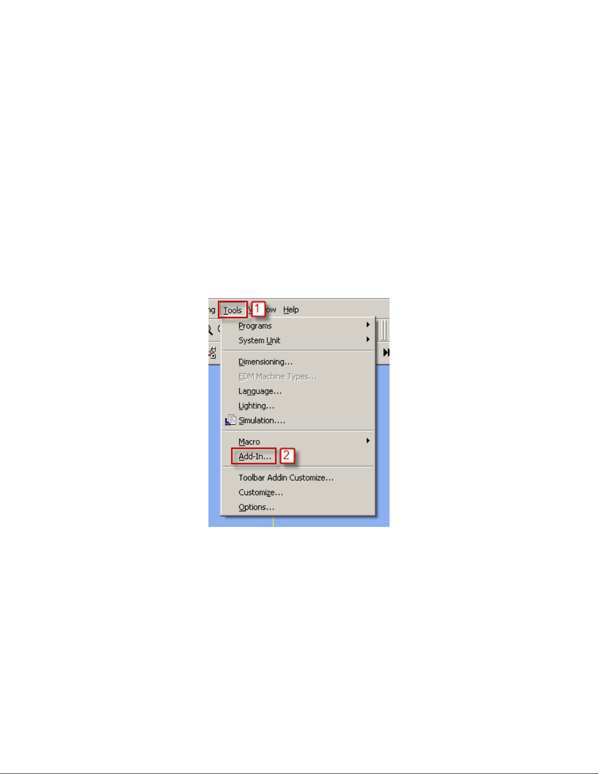
To load an add-in in ESPRIT, from the Tools menu, select Add-In...:
1
Page 9
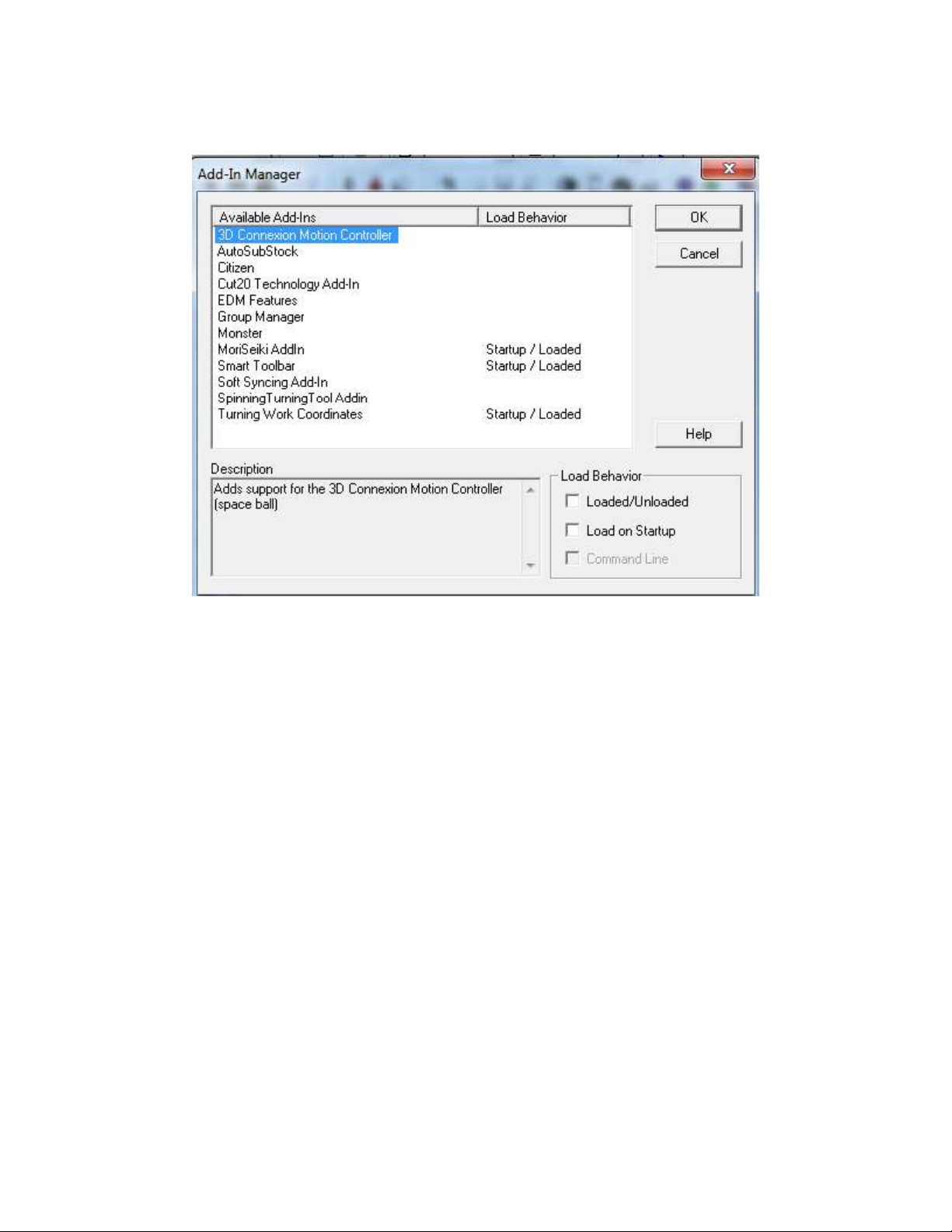
You will then see the add-in window:
2
Page 10
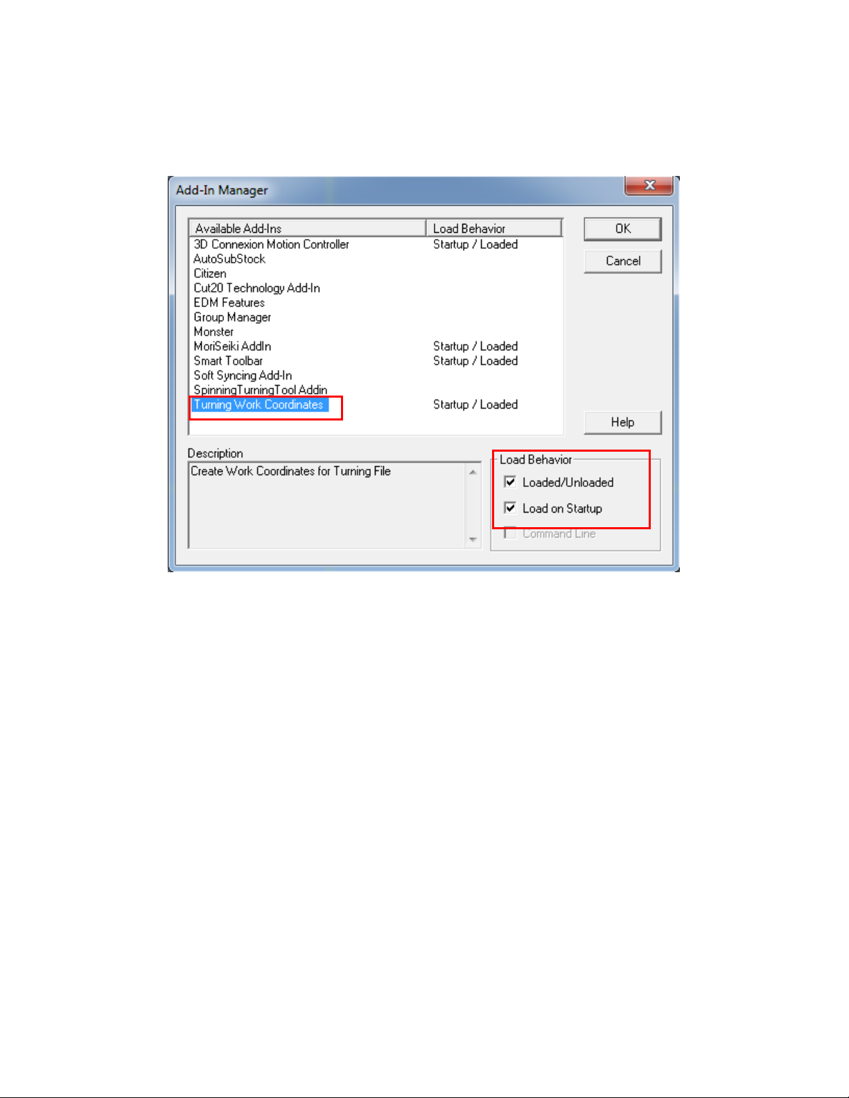
To load an add-in, highlight it in the Available Add-Ins list and check in Load Behavior
the box Loaded/Unloaded.
Check box Load on Startup so the addin will automatically load each time you start
ESPRIT
For the Mori Seiki NT series, you will need to load the following add-ins:
Turning Work Coordinates
Optional Addins that can also be loaded if needed:
Spinning Turning Tool Addin
AutoSubStock
3
Page 11
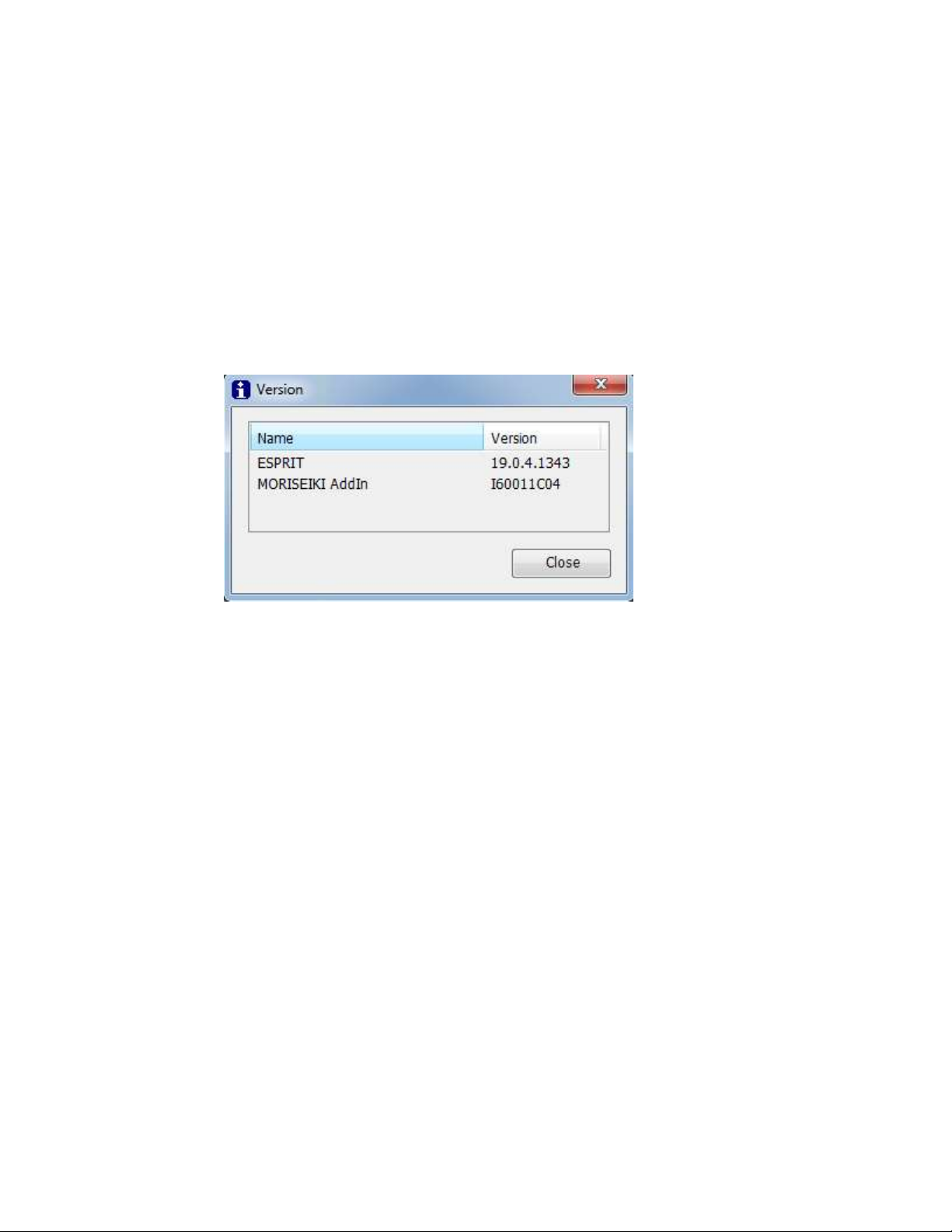
2.2. Mori Seiki ESPRIT for Mapps Addin
Installation of the Mori Seiki ESPRIT for MAPPS Addin is required. The Mori Seiki addin has a
number of components that are required for the programming of the Mori Seiki NT machines.
The Mori Seiki ESPRIT for MAPPS Addin is installed with the Mori Seiki Global installer.
The Mori Seki AutoPark addin is integrated with the ESPRIT Utilities.
ESPRIT for MAPPS addin version I60011C04 or newer is required
4
Page 12
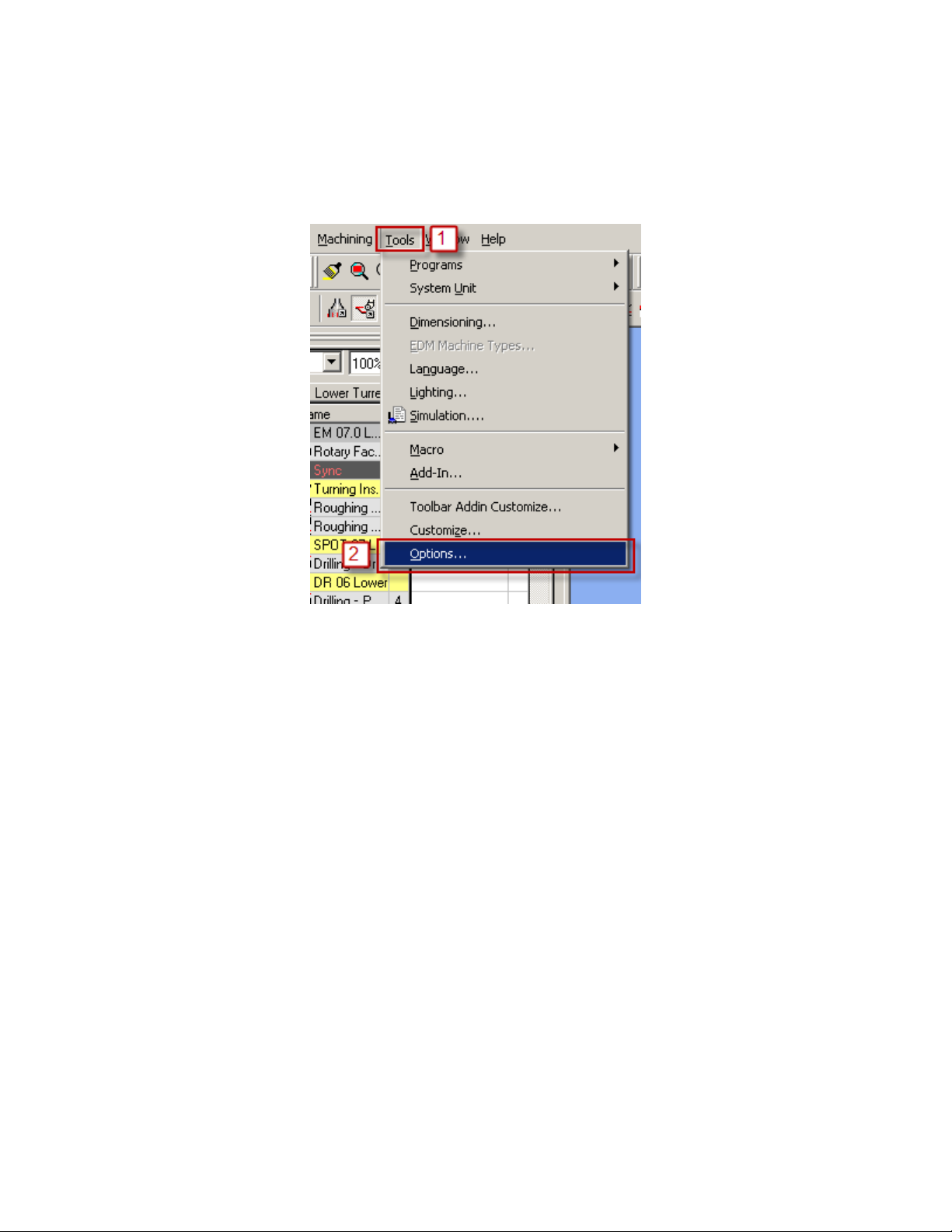
2.3. Stock Automation
In ESPRIT, from the Tools menu, select Options...
5
Page 13
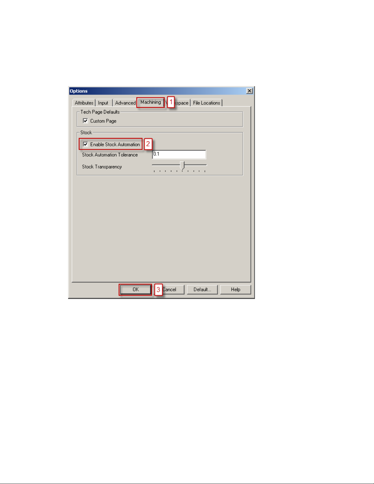
On the Machining tab, if you check Enable Stock Automation, The AutoSubStock add-in should
not be used since the Stock Automation will compute the state and shape of your stock present in
both the spindle 1 and spindle 2:
Please refer to the ESPRIT help file for additional information on stock automation.
6
Page 14
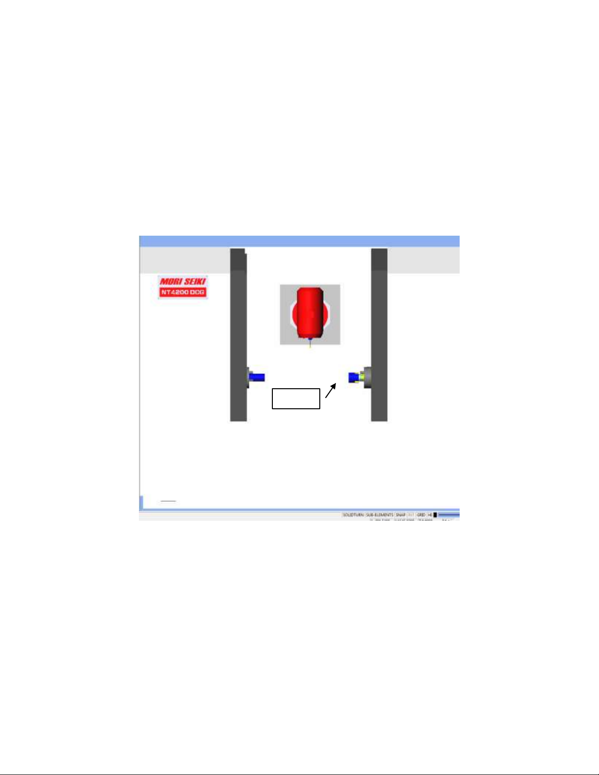
SubStock
2.4. AutoSubStock (optional)
Important note: Note: If the Stock Automation function (above) is used, do not use the
AutoSubStock Addin.
The AutoSubStock add-in needs to be turned on prior to opening a file. This add-in will allow
you to correctly simulate the sub spindle work. It will also allow the simulation of production
work, when cutting on the main and the sub spindles at the same time.
Once you are done programming a part, simply play the entire simulation and once complete
click on Auto Sub Stock. This will save the sub stock in the sub spindle and stop the simulation.
If you restart the simulation, you will be able to see the cut on the main and sub spindles side all
at the same time.
7
Page 15
2.5. Turning Work Coordinates Addin
The Turning Work Coordinate add-in will sort your operations in the appropriate work
coordinates and also offset the NC code for the sub spindle operations. It is necessary to run this
add-in in order to generate correct NC code.
When the Addin is run the operations that have the Main Spindle selected will go under the
Work Coordinate (WC) created for the Main Spindle and the operations that have the Sub
Spindle. If an operation(s) are machined with the B axis at an angle other than -90, 0, +90 will be
placed in a “Baxis” version of the WC for the spindle the “tilted” operation is working on.
2.5.1. Setting Up the Turning WC addin
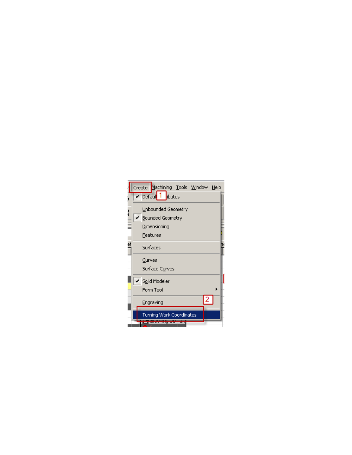
When first staring a new file in Esprit from the Create menu, select Turning Work
Coordinates.
You will then see the Turning Work Coordinates dialog:
8
Page 16
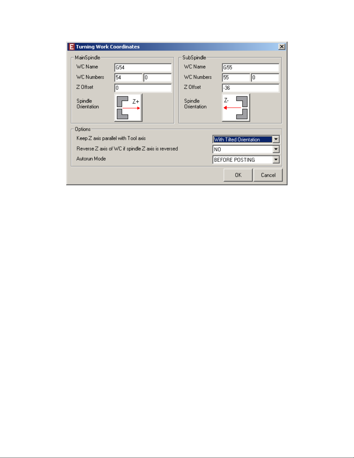
The Turning WC addin will look at your Machine Setup file and determine how the dialog
box needs to be setup for your machine. The Spindle names and orientation information in
the dialog box are taken directly coming from the Machine Setup.
WC Name: Corresponds to the Work Coordinate name. Please note that the name is just
informative and will not affect the NC code. This name will appear in the feature list inside
of Esprit.
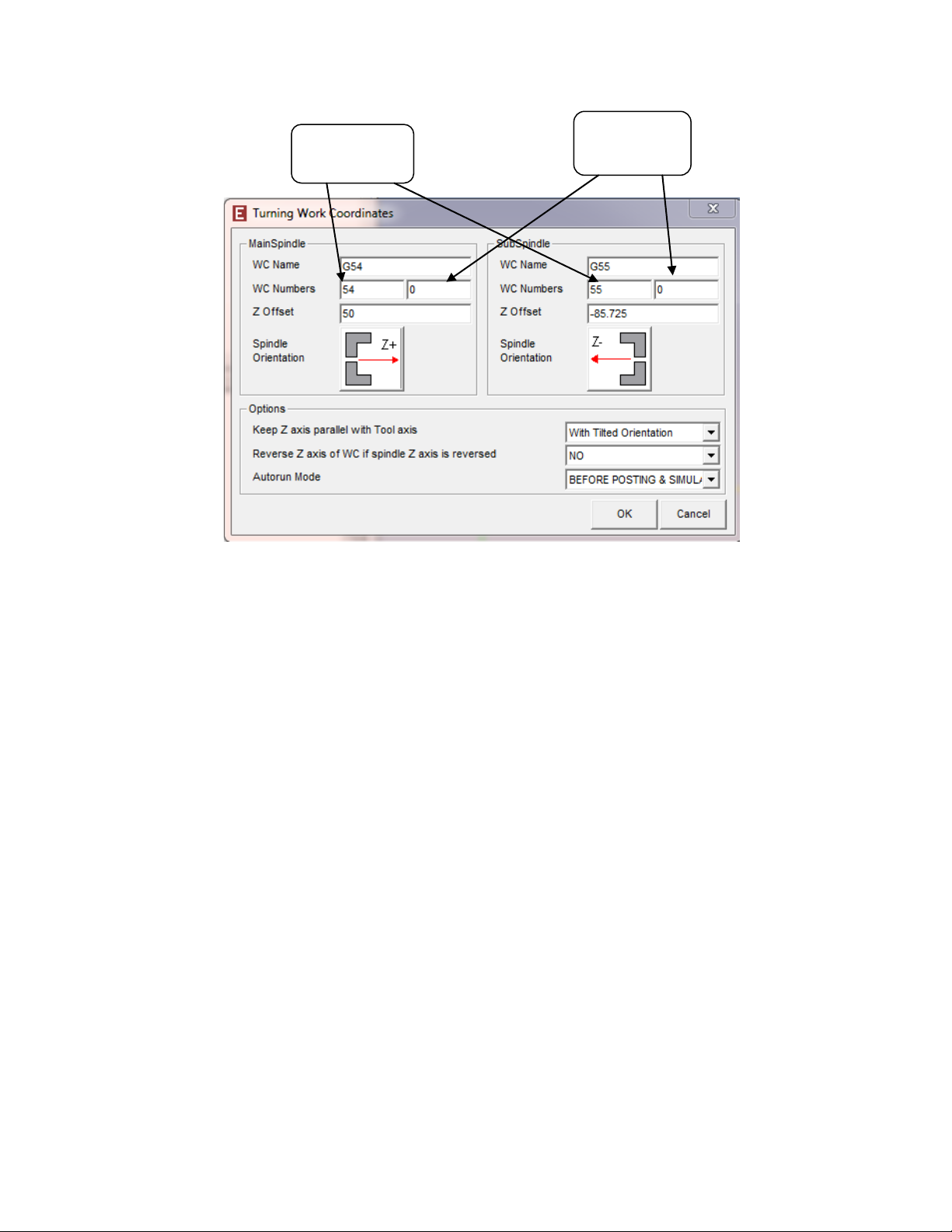
WC Numbers: Both fields are used by the post. The Machine control has two sets of
offsets that can be used. The standard work coordinates (G54-G59) and the extended work
coordinates (G54.1 Pxx)
9
Page 17
Standard
WC Field
Additional
WC Field
o The Standard WC number is used to output G54-G59. Enter 54 to have G54 in
NC code. 55 to have G55 in NC code, etc. If a machine is equipped with 2
spindles a value must be set for both spindles. When using the machines Standard
Work Coordinates (G54-G59) a zero (0) must be entered into the Additional
offset field.
Note: The NT1000 post has G59 is reserved for use on the Sub spindle when it is
tilted. If programming an NT1000 do not enter 59 into a WC in Esprit) .
o The Additional WC number is used to output extended work coordinate in the NC
code (G54.1 Pxx). For example if a 1 is entered into the Additional WC filed a
G54.1 P1 will be output in the NC code. When outputting the extended work
coordinates (G54.1 Pxx) a value of zero (0) must be entered into the Standard WC
field.
Z Offset: Used to setup the location of the work coordinates in Esprit. This is most
commonly only used for the sub spindle.
o Main Spindle: Typically set to zero. This means the program zero for main
spindle is P0 (World Zero) in Esprit.
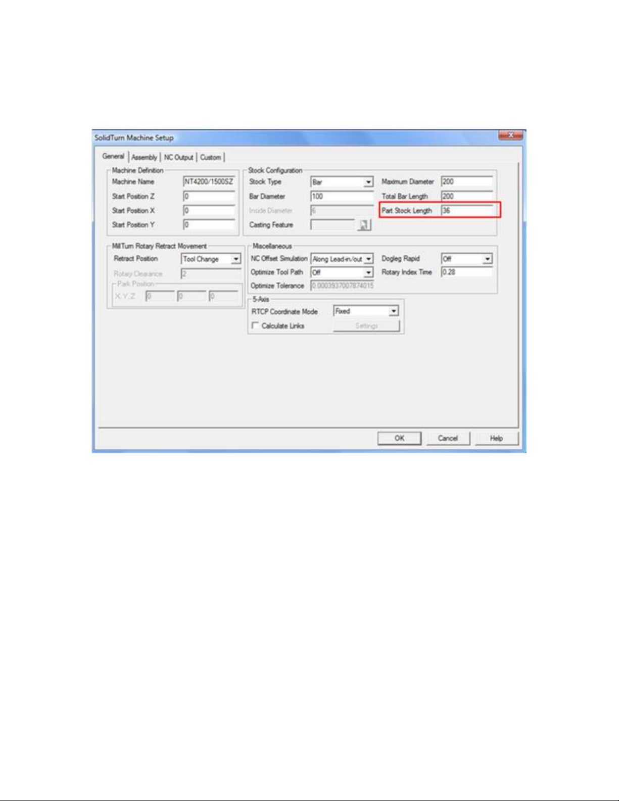
o Sub Spindle: The sub spindle value is typically set to the negative value of the
finish part length. The value is pre-loaded from the Part Stock Length field of the
Machine Setup (on the General tab). For example if the finish part length is
100mm you would enter -100 in the Sub Spindle Z offset Field. The work
coordinate will be offset by minus this amount from P0.
10
Page 18
o The Z offsets MUST have the correct values in them to have correct Z axis values
in your NC code.
Spindle Orientation: This information is coming from the Machine Setup and is just
informative.
11
Page 19
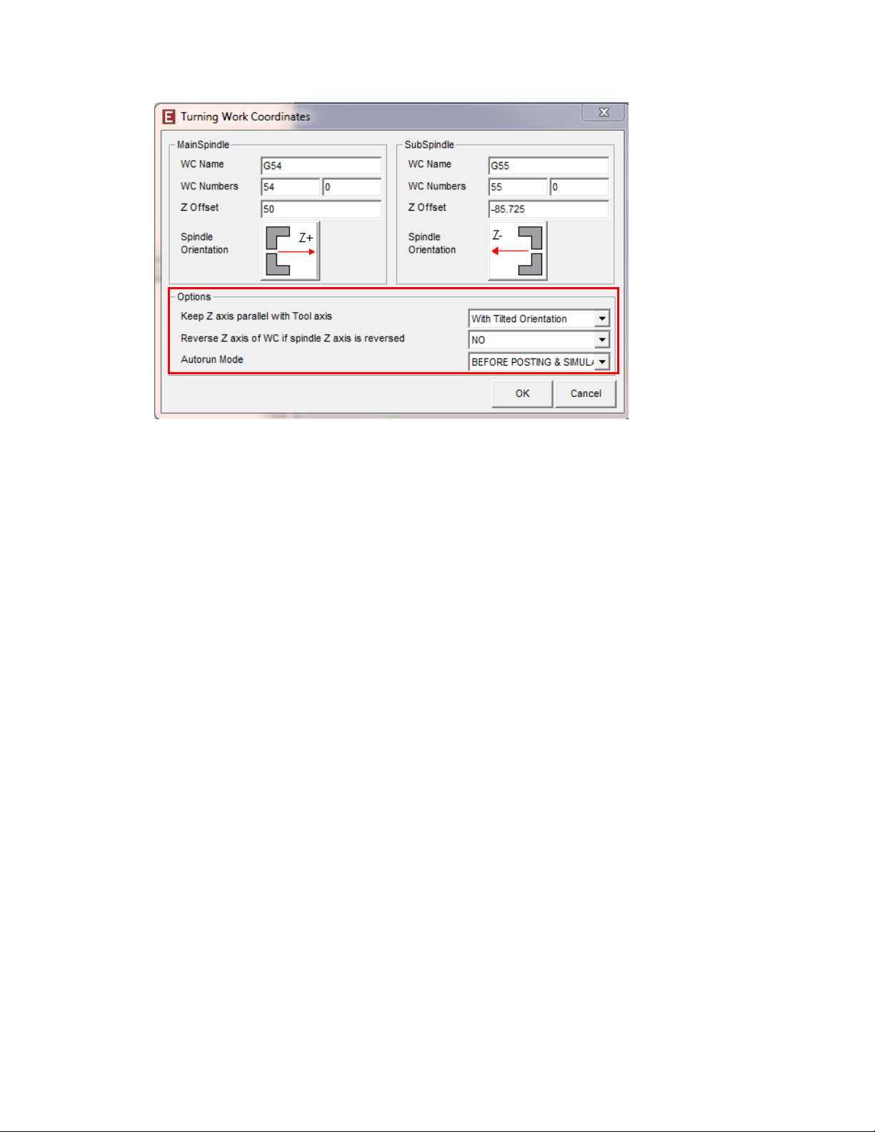
Options Section:
Keep Z axis parallel with Tool axis: This MUST be set to “With Tilted Orientation”
Reverse Z axis of WC if spindle Z axis is reversed: MUST be set to NO
Auto Run Mode: it is best to have the “Before Posting and simulation” Option selected.
This will cause the addin to run every time you simulate and post NC code and ensure
that the operations fall under the correct WC, this ensuring your NC code is correct.
2.6. AutoPark Addin (required on NT1000 machines)
The ESPRIT AutoPark addin was designed to help users park the turrets to the extreme travel
limits without having known the exact location of the travel limits in the machine coordinate
system. The NT machines are setup to use the Auto Park addin to positions the Head\Turret to
the left most position in the travel envelop of the NT machines.
In addition the AutoPark addin is used to position the A axis (Sub Spindle) in the NT1000
machines to ensure correct NT code and simulation.
The AutoPark Addin is only for use with ESPRIT 2012 or newer and the ESPRIT 2012 or newer
Mori Seki addin.
In addition the AutoPark addin will only function correctly if you have the latest Machine Setups
created for the ESPRIT 2012 or newer packages. ESPRIT files created prior to ESPRIT 2012
will need the Machine Setup pages updated to use the AutoPark addin.
12
Page 20

For information as to how to use the addin please refer to the Setting up the park operation with
the AutoPark addin and Setting A-axis Position with the AutoPark Addin sections of this
manual.
13
Page 21
1
2 3 4
5
3. Machine Setup
3.1. Introduction
Some important settings regarding the NC output are set in the Machine Setup.
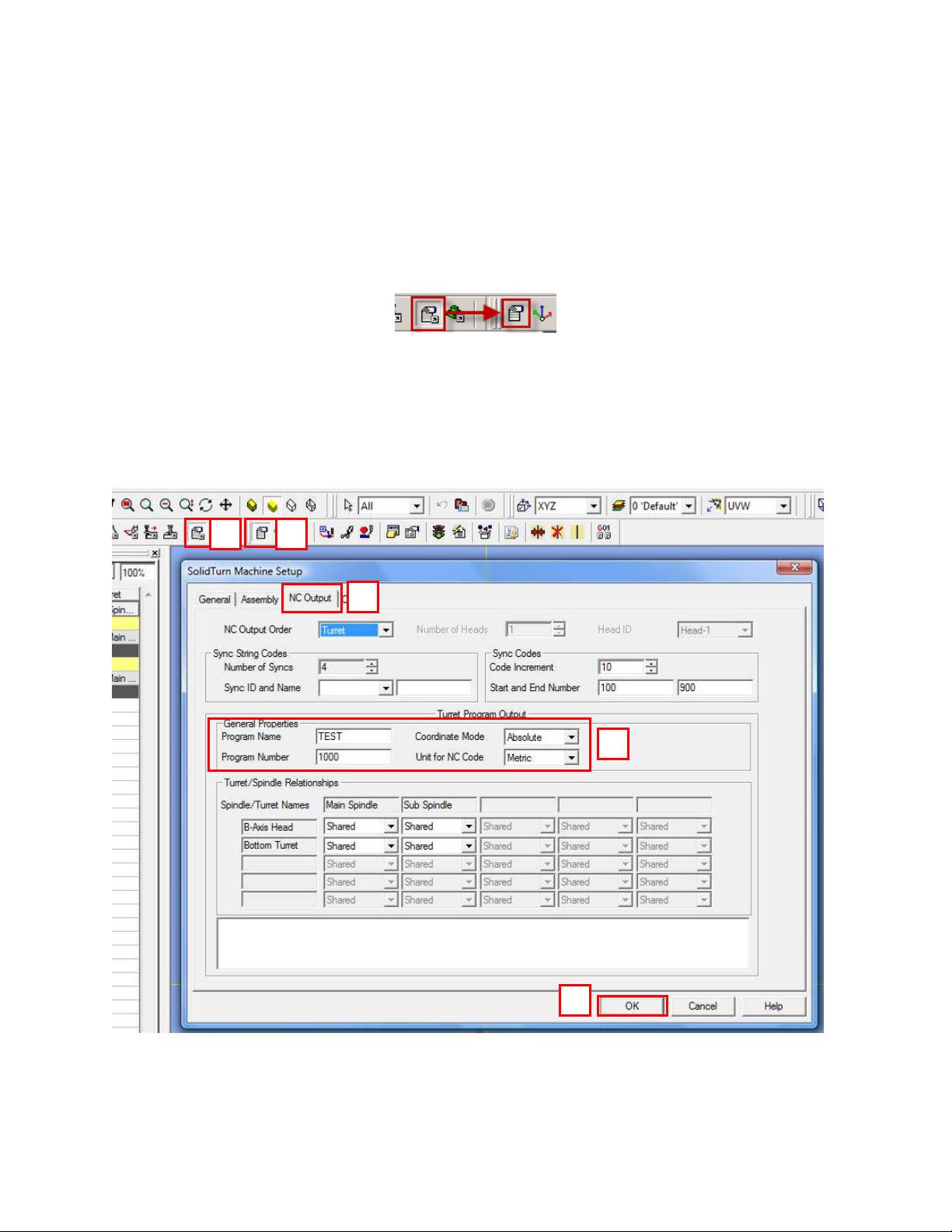
To open the Machine Setup, click on Common Machining and then on Setup:
3.2. Set the Program Name, Program Number
To set the program name and number output at the beginning of your NC code on each channel,
you will need to go to the NC Output tab of the Machine Setup. Under General Properties of the
Turret Program Output, enter the name of your program, its number. You can also specify here
the unit of your NC code and the coordinate mode.
14
Page 22
3.3. Define the Turning Stock
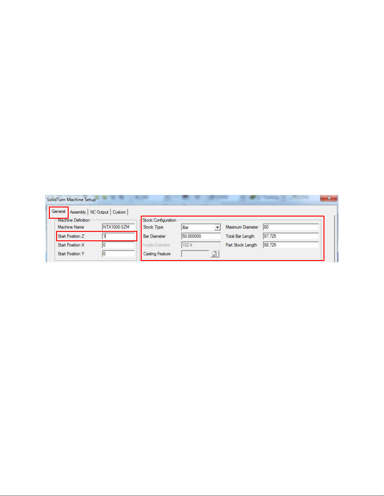
On the General tab of the Machine Setup, you can define your turning stock. For turning
operations, if you are using the Stock Type Automation, your NC output will be linked to the
defined turning stock.
Use Start Position Z to position the stock along the Z axis. It will be used, for example, to define
the front face facing amount.
Use Stock Type to define the shape of your stock: Bar, Tube (Inside Diameter will then be
available) or Casting (Casting Feature will then be available for selection).
Use Bar Diameter to specify the diameter of your stock.
Use Total Bar Length to define the total length of your stock.
Finally use Part Stock Length to define the length of your finish part. This will be used by the
Turning Work Coordinates add-in.
Note: ESPRIT supports a number of different stock configurations. Please consult the ESPRIT
Help file for detailed information.
15
Page 23

In order to use the stock configuration from the machine setup dialog box you must have the
Simulate Turning Stock field (Found in the Simulation Parameter dialog box) checked (as shown
below):
16
Page 24
3.4. Tool Path Optimization with NURBS
With the Mori Seiki NT series machines, it is possible to translate non-uniform rational B-splines
(NURBS) used in modeling sculptured or curved surfaces directly in NC units. This is especially
helpful when programming complex three dimensional molds and tool dies.
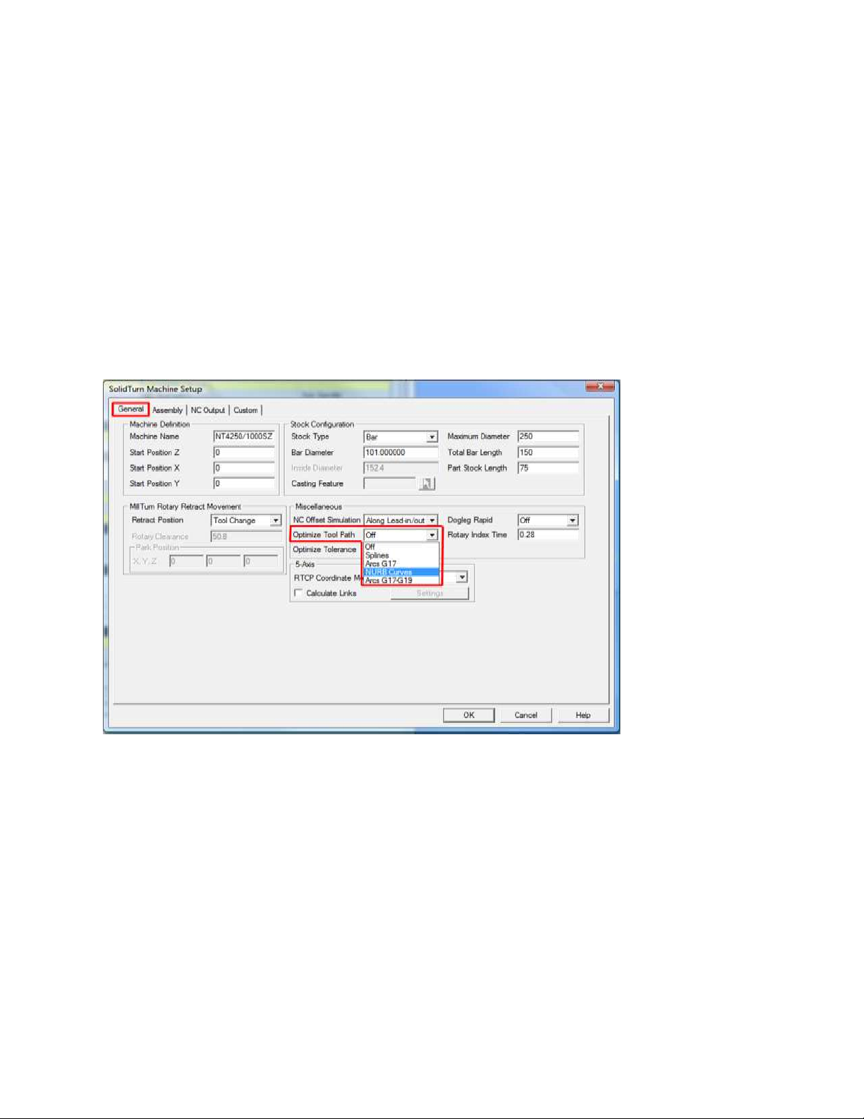
To turn on NURBS Optimization in ESPRIT, navigate to the Machine Setup page and the
General tab. Under “Miscellaneous” there is a pull down labeled “Optimize Tool Path” open this
and scroll down to “NURBS Curves” to select NURBS optimization. Click OK to complete this
function.
Machine Setup General Tab
17
Page 25
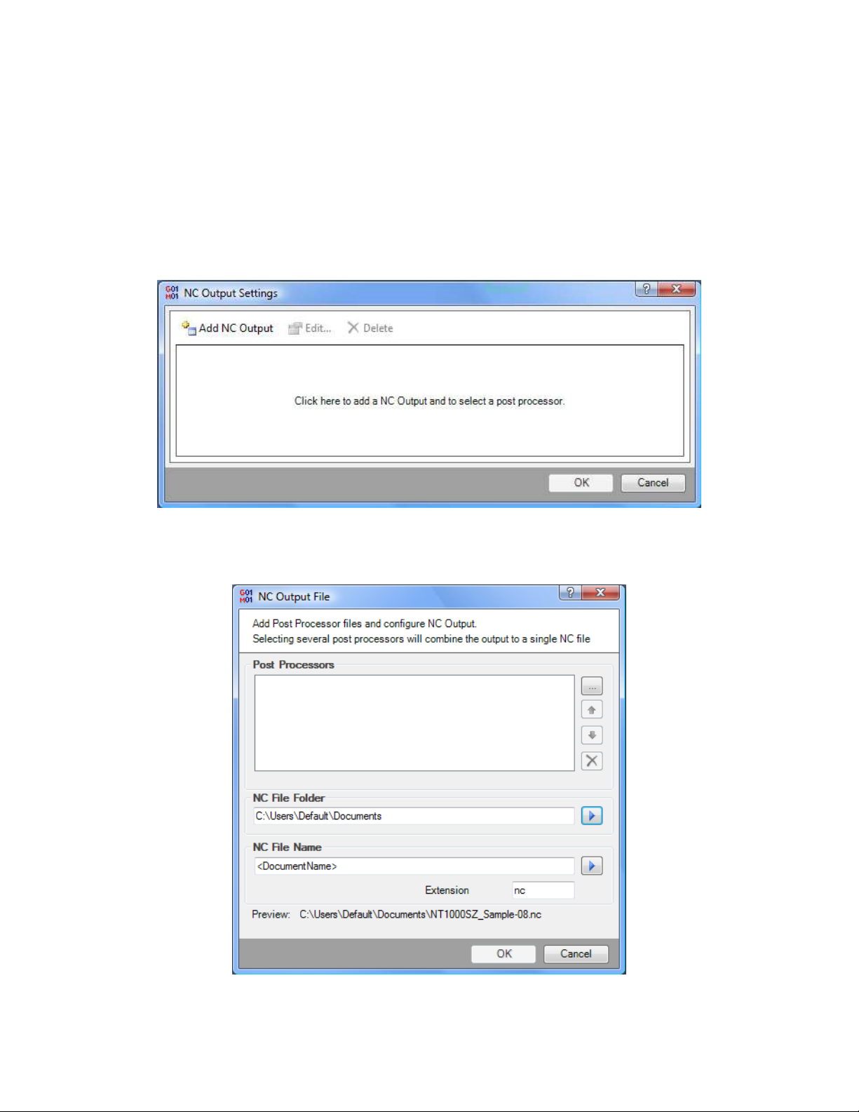
3.5. Selecting Post Processors and Outputting NC Code
Starting in ESPRIT 2011, there is now a new tool to output NC code from any ESPRIT file.
Now, the user simply needs to select NC Code from the Common Machining toolbar. The first
time that NC code is posted, ESPRIT will prompt the user to select the file location of the post
processor(s) to be used. The user will see the following window pop up upon first selecting NC
Code:
By selecting the “Add NC Output” button, the user is able to select the appropriate file location
for their post processor as well as determine the file location of the resultant NC code as well as
the name of the NC code file and file extension type:
18
Page 26
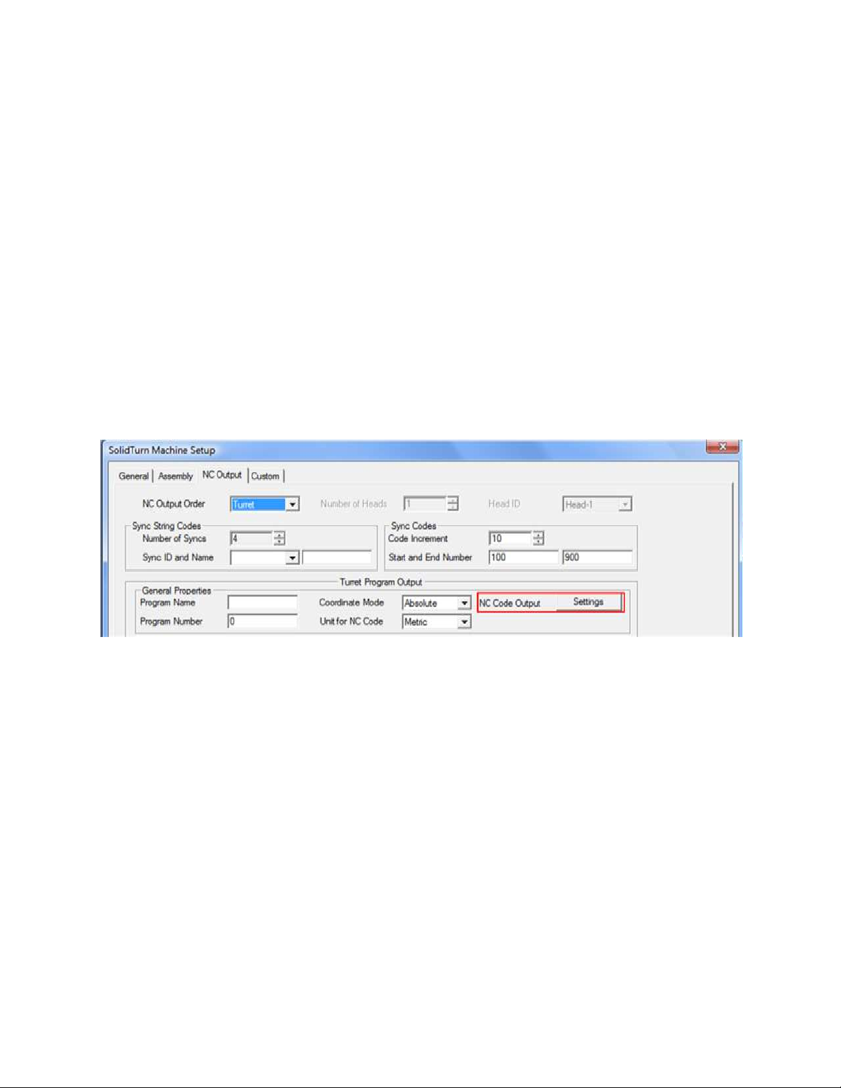
For multi-turret machines such as the NT-SZ, NT1000WZ and NT1000SZ, the user should select
each turrets post processor separately and give each file a unique NC File Name. Once the user
has selected one post processor, they are able to select Add NC Output again and create a new
NC Output file for the other post processor, again with a unique NC File Name.
Once the user selects all necessary post processors and selects OK from the NC Output Settings
window, NC code will be generated and appear in the users selected NC code editor.
The next time the user chooses NC Code from the Common Machining toolbar, the NC code will
automatically be generated, without having to interface with the NC Output Settings window
again.
Note: If the user receives new post processors or would like to make any changes to the file
location or file name, they are able to do this by navigating to the Machine Setup in the Common
Machining toolbar. On the “NC Output” tab, there is a section on the right hand side called NC
Output Settings that will bring the user back into the NC Output Settings window and allow them
to make the necessary changes.
19
Page 27
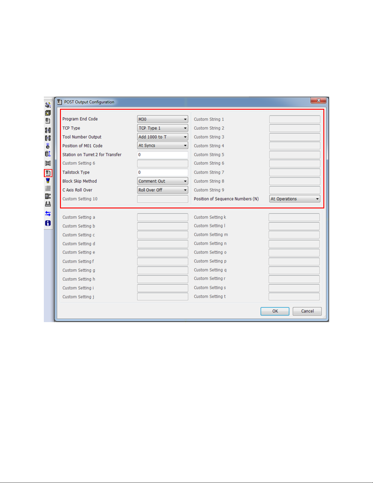
3.6. Machine Parameters
3.6.1. Introduction
Machine parameters can either be set on the Machine Parameters tab of the Machine Setup
Utility (part of the MoriSeik AddIn).
3.6.2. Output of Program End (M02), Sub-Program End (M99) or
Program End and Rewind (M30)
On the POST Output Configuration, set Program End Code to M02 to output M02, set it to
M30 to output M30 or set it to M99 to output M99 at the end of the NC code of each turret.
Please note that M30 is the default.
20
Page 28

3.6.3. TCP Type
This setting is to choose between G43.4 and G43.5 modes when machining in 5 axis
simultaneous mode. Type 1 is G43.4 and Type 2 is G43.5. Please see section 5-axis
Simultaneous Milling Options for more information on these options.
3.6.4. Set position of optional stop code (M01) in the NC code.
Upper head only machines (turrets (NT-S, NT1000-S, NT1000-W) have 2 options for outputting
the optional stop code (M01).
At Operations (at the end of every operation)
At Tool Cancel (at the end of a tool or at the end of an operation where the B axis angle,
spindle changes, or anything else that causes the post to output tool cancel section of NC
code)
By default, optional stop codes are output at the end of every operation.
Machines equipped with a lower turret (NT-SZ, NT1000-SZ, NT1000-WZ) have an a 3 options
for outputting the optional stop code:
At Syncs (at every sync in the ESPRIT file’s operation list)
At Operations (at the end of every operation as well as at every sync)
At Tool Cancel (at the end of a tool or at the end of an operation where the B axis angle,
spindle changes, or anything else that causes the post to output tool cancel section of NC
code, as well as every sync)
By default, optional stop codes will be output on each head after sync codes in the NC code
on a lower turret machine this way, optional stop can be turned on while running the NC
code on both heads at the same time (production mode).
The “At Operations” and “At Tool Cancel” can only run with the optional stop mode on
when running the machine at one head at a time (NC code proofing mode).
3.6.5. Station on Turret 2 for Transfer
If this value is not zero, this station 1 will be used as empty station during part transfer and part
release on release operations in the lower turret (NT-S and NT-SZ). If the tool station for is left
zero the turret will be left at the current station when the turret is parked by the transfer section in
the post.
By default this value is 0
21
Page 29

Note: The lower turret can be parked to the lower turret park location with the park operation
before the transfer is programed. If this is done, the post will not move the turret or change the
station of the turret even if this setting is not zero.
For additional information see the Park Cycles section of this manual.
3.6.6. Tail Stock Type
This option is used to determine an “independent” tail stock is in the sub spindle of the machine
used as a live center or a standard tails stock mounted on the machine.
If a value of 0 is entered in the Tail Stock Type setting, the post will assume the machine is using
an independent tail stock.
If a value of 1 is entered the post will assume the center is in the sub spindle of the machine.
By default this setting is 0
For additional information see the Tailstock section of this manual.
3.6.7. Block Skip Method
When using spindle priority on turning cycles on lower turret type machines (see part Other
Turning Cycles section for additional information), you can use choose which symbol will be
output to skip the turning spindle control (spindle start and spindle stop as well as the spindle
speeds) on the slave turret.
Comment Out will put the spindle commands inside of a comment as follows “( G97 S2139
M04 )” in the slave turrets program
Block Skip will output a block skip “/” before the spindle commands in the slave turrets program
Block Skip 2 will output a block skip “/2” before the spindle commands in the slave turrets
program
By default Comment out is used.
3.6.8. C-Axis Rollover
For the Mori Seiki NT-SZ machine, it is sometimes necessary to limit the C-axis rotation angle
to between -360 and 360 degrees.
Roll Over Off will turn off roll over in the post.
Roll Over On will turn on C-axis roll over in the post.
By default Roll Over Off is used.
22
Page 30

The Roll over function will need to match the mode of the machines control:.
On machine control, if <Roll over for C-axis> is invalid
(NC Parameter 1008 bit 0 = 0):
min. C-axis value is -99999.999°
max. C-axis value is +99999.999°
In ESPRIT use Roll Over Off
On machine control if <Roll over for C-axis> is valid
(NC Parameter 1008 bit 0 = 1):
min. C-axis value is -359.999°
max. C-axis value is 359.999°
In ESPRIT use Roll Over On
When C-axis roll over is on, C-axis will be indexed between -360° and 360°:
C-axis will be indexed with C values.
SolidMillTurn 4-axis wrap and rotary operations with interpolation off cannot be
programmed.
23
Page 31
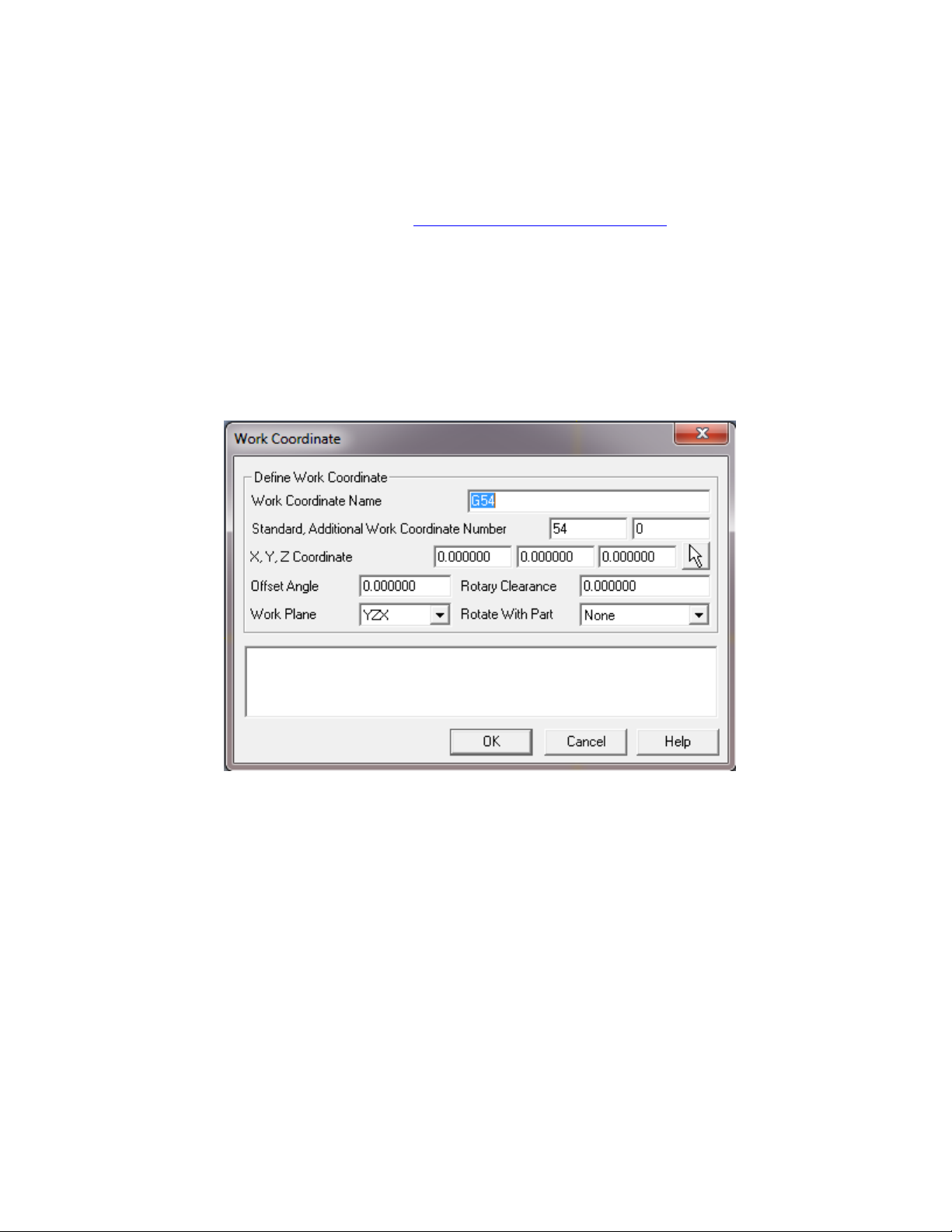
4. Work Coordinates
The most trouble free method of setting up Work Coordinates in Esprit is by using the Turing
Work Coordinate Addin as described in Turning Work Coordinates Addin section. However the
NT post will allow you manually setup the work coordinates in the Esprit file.
The only reason to setup work coordinates manually would be to have more than one offset per
spindle.
To setup Work coordinates manually care must be taken to ensure the work coordinates are
properly created\setup as well as every operation is under the correct work coordinate.
The Standard WC number is used to output G54-G59. Enter 54 to have G54 in NC
code. 55 to have G55 in NC code, etc. If a machine is equipped with 2 spindles a value
must be set for both spindles. When using the machines Standard Work Coordinates (G54G59) a zero (0) must be entered into the Additional offset field.
Note: The NT1000 post has G59 is reserved for use on the Sub spindle when it is tilted. If
programming an NT1000 do not enter 59 into a WC in Esprit) .
The Additional WC number is used to output extended work coordinate in the NC code
(G54.1 Pxx). For example if a 1 is entered into the Additional WC filed a G54.1 P1 will
be output in the NC code. When outputting the extended work coordinates (G54.1 Pxx) a
value of zero (0) must be entered into the Standard WC field.
XYZ coordinates: X and Y values are typically left at 0, Z can be any value desired to
shift the offset from the selected work plane.
24
Page 32

Offset Angle: Must be set to 0
Rotary Clearance: is not currently used by the NT posts
Work Plane: it is Critical that the Work plane selected is either YZX or a plane that is
parallel to the YZX plane.
Rotate with Part MUST be set as follows:
o For turning operations any MillTurn operations at B-90, B0, and B90 set this to
“None”
o For any MillTurn operation that is NOT at B-90, B0, and B90, set this to “Point
only”
For additional information on the use of work coordinates please refer to the help file within
ESPRIT.
25
Page 33
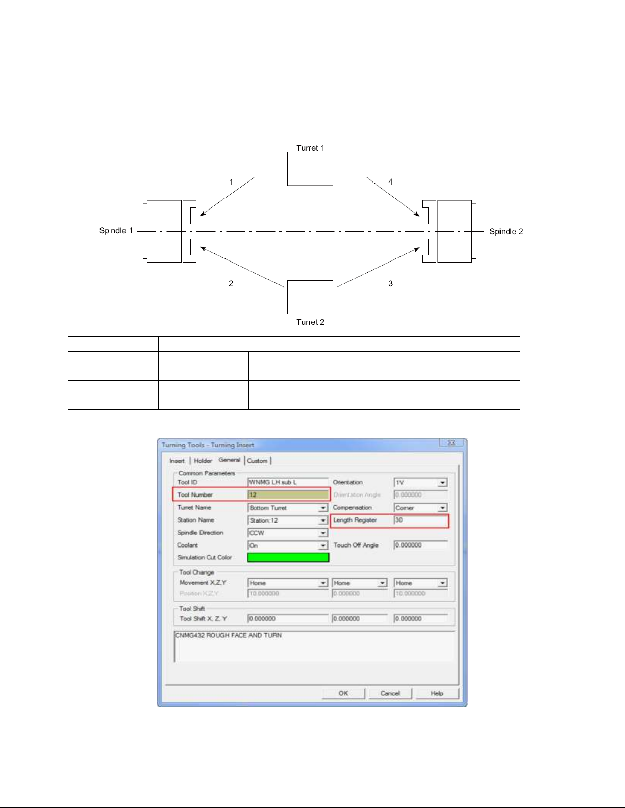
Turret and Spindle to Use
T Code to Specify
1
Turret 1
Spindle 1
T1001 – T1099
2
Turret 2
Spindle 1
T0101-T1212
3
Turret 2
Spindle 2
T0131 – T1242
4
Turret 1
Spindle 2
T1001 – T1099
5. Tools (T-function)
5.1. T-function Specifications
Turning Tool General Page:
26
Page 34
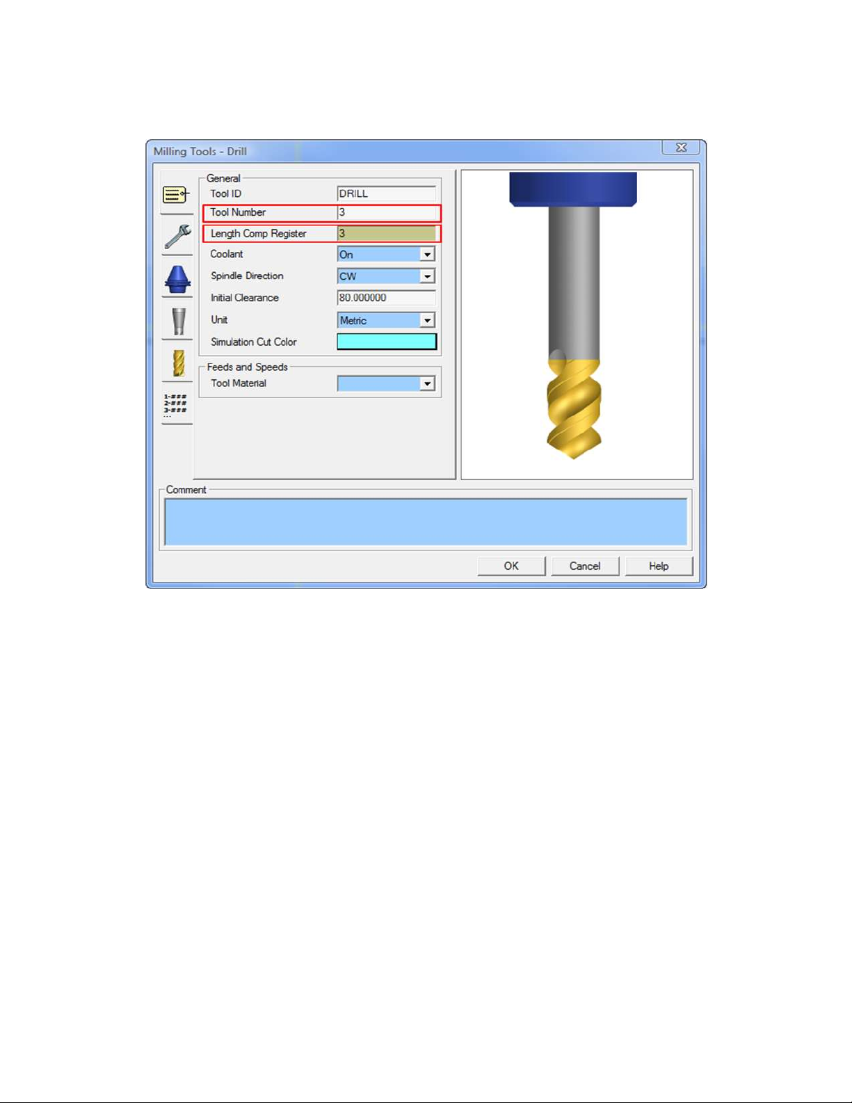
Milling Tool General Page:
27
Page 35
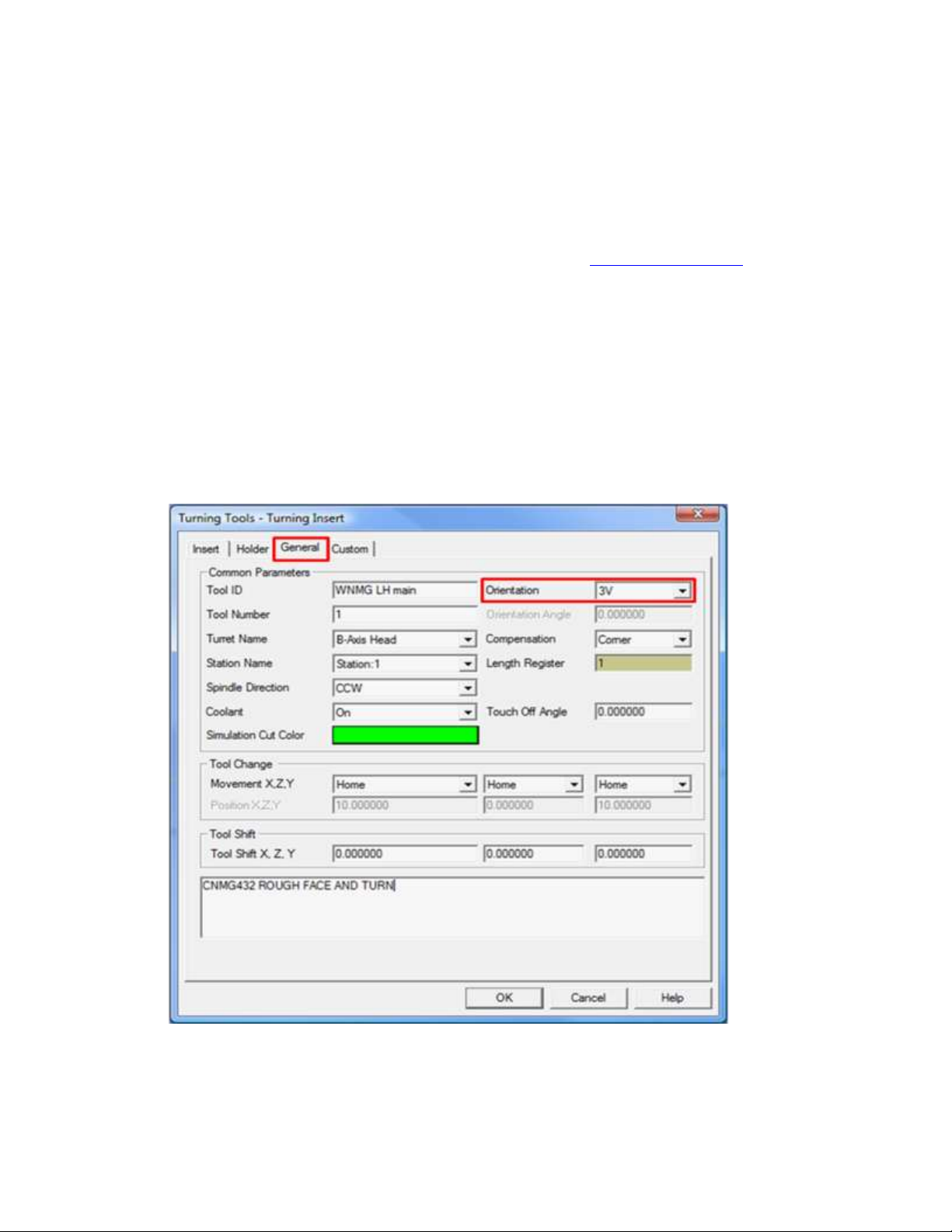
5.1.1. Upper Head (B-Axis Head):
For the NT machine series when machining on Spindle 1 (Main Spindle) or Spindle 2 (Sub
Spindle) with the tool mounted in the Tool Spindle (Head1/B-Axis), if the “Tool Number
Output” option in the Post Output Configuration “Tool Number Output” will determine if the
post processor will add 1000 to the number entered or not. (See Machine Parameters)
If the “Tool Number Output” is set to “Add 1000 to T” and the tool number entered into the tool
page is less than 1000, the post will add 1000 to the T code. If not, the tool number will be
output as entered on the tool’s dialog box
NOTE: All turning tools that are defined on the B-Axis head for the NT series machines should
be set on the “General” tab of the tool page in either a “3V” or “4V” orientation (whichever is
the position of the tool in the D1 orientation of the milling spindle). ESPRIT will automatically
adjust the B-Axis head angle to the correct orientation based on the tool orientation selected in a
given machining operation.
28
Page 36

5.1.2. Lower Turret:
For the NT machine series when machining on spindle 1 (Main Spindle) with the tool mounted
on the Lower Turret (Head 2/Turret 2), the tool number will be output directly as entered in the
Tool Number Dialogue Box. If 1010 is entered in the Tool Number Dialogue Box, T1010 will be
output in the NC code. Also, if the user has entered three numbers in the Tool Number Dialogue
Box, the post processor will add a leading 0 to the tool number. If 101 is entered in the Tool
Number Dialogue Box, T0101 will be output in the NC code.
In the event that the user has entered two or less numbers in the Tool Number Dialogue Box, the
post processor will combine the numbers in the Tool Number Dialogue Box and the Length
Register (Length Comp Register for milling tools) Dialogue Box. If 10 was entered in the Tool
Number Dialogue Box and 27 was entered in the Length Register Dialogue Box, 1027 will be
output in the NC code.
For the NT machine series when machining on spindle 2 (Sub Spindle), the post processor will
add 30 to the tool number entered in the Tool Number Dialogue Box if that tool is mounted on
the Lower Turret (Head 2/Turret 2). If 1010 is entered in the Tool Number Dialogue Box, T1040
will be output in the NC code. Also, if the user has entered three numbers in the Tool Number
Dialogue Box, the post processor will add a leading 0 to the tool number. If 101 is entered in the
Tool Number Dialogue Box, T0131 will be output in the NC code.
In the event that the user has entered two or less numbers in the Tool Number Dialogue Box, the
post processor will combine the numbers in the Tool Number Dialogue Box and the Length
Register (Length Comp Register for milling tools) Dialogue Box and add 30 to the combination.
If 10 was entered in the Tool Number Dialogue Box and 27 was entered in the Length Register
Dialogue Box, 1057 will be output in the NC code.
29
Page 37
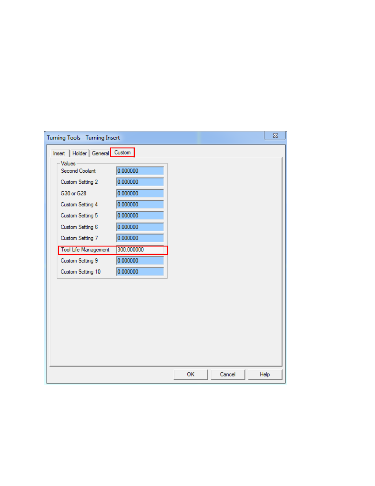
5.2. Tool Life Management
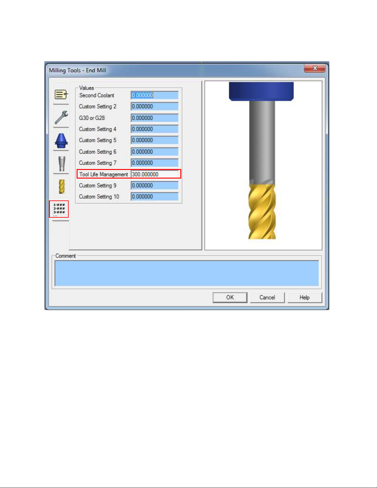
For the Mori Seiki NT Series machines, it is possible to use Tool Life Management to record
data about a particular tools usage. To turn on Tool Life Management, navigate to the Custom
tab of the Tool Page and set the “Tool Life Management” setting to 100 (Tool Custom Setting 8).
This will output an M300 at the end of each operation with that tool and also modify the tool call
depending on if you are using a milling or turning tool.
Turning tool page:
30
Page 38
Milling tool page:
31
Page 39
5.3. Tool Nose Direction (G43 H_ T_)
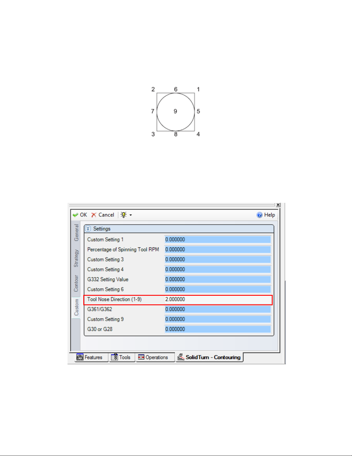
When using a turning tool in the B-axis head of the Mori Seiki NT, it is possible to specify the
direction of the tool nose to be offset according to the following diagram:
The corresponding G code is:
G43 H_. T_.
To program this in ESPRIT, go to the Custom tab of any operation using a turning tool and set
the Tool Nose Direction (1-0) (Custom Setting 7) field to any value between 1 and 9. Values >9
or <1 will omit the T_ output.
32
Page 40
5.4. Second home position
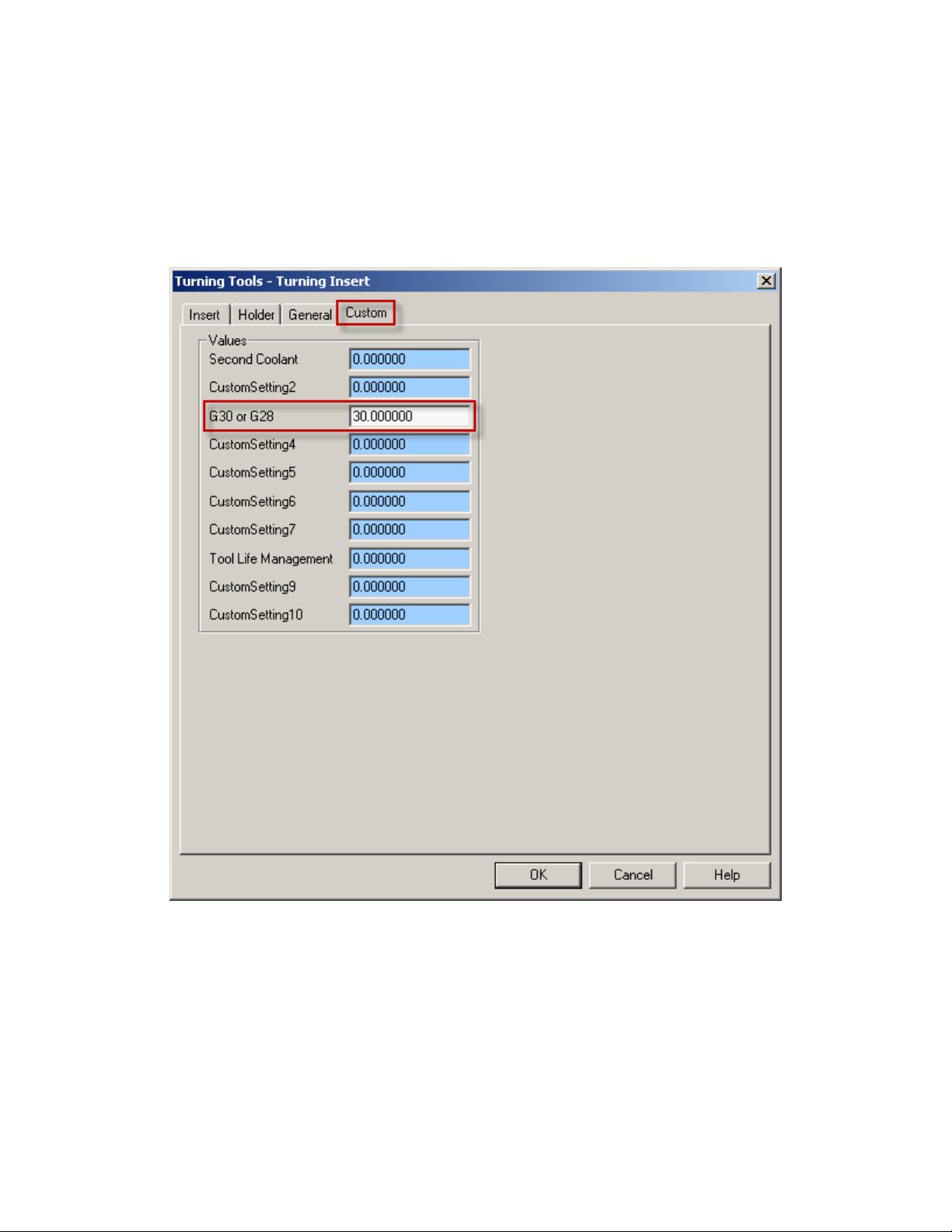
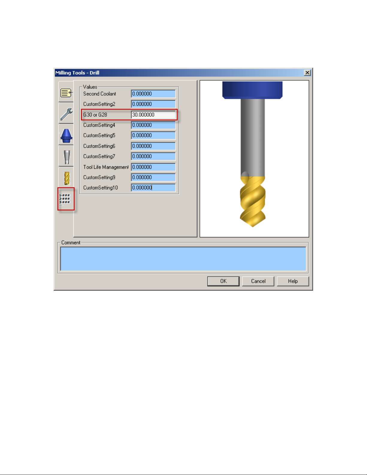
On the Custom tab of the tool page, set “G30 or G28” setting to 30 (Tool Custom Setting 3) to
use the second zero return of the machine (G30 P4) for this tool.
Turning tool page:
33
Page 41
Milling tool page:
:
This will trigger the output of G30 P4 (instead of G28) whenever a turret needs to be sent home.
If you omit (or enter a wrong value) to enter the value in this field, turrets will be sent to the
machine zero point with G28.
34
Page 42
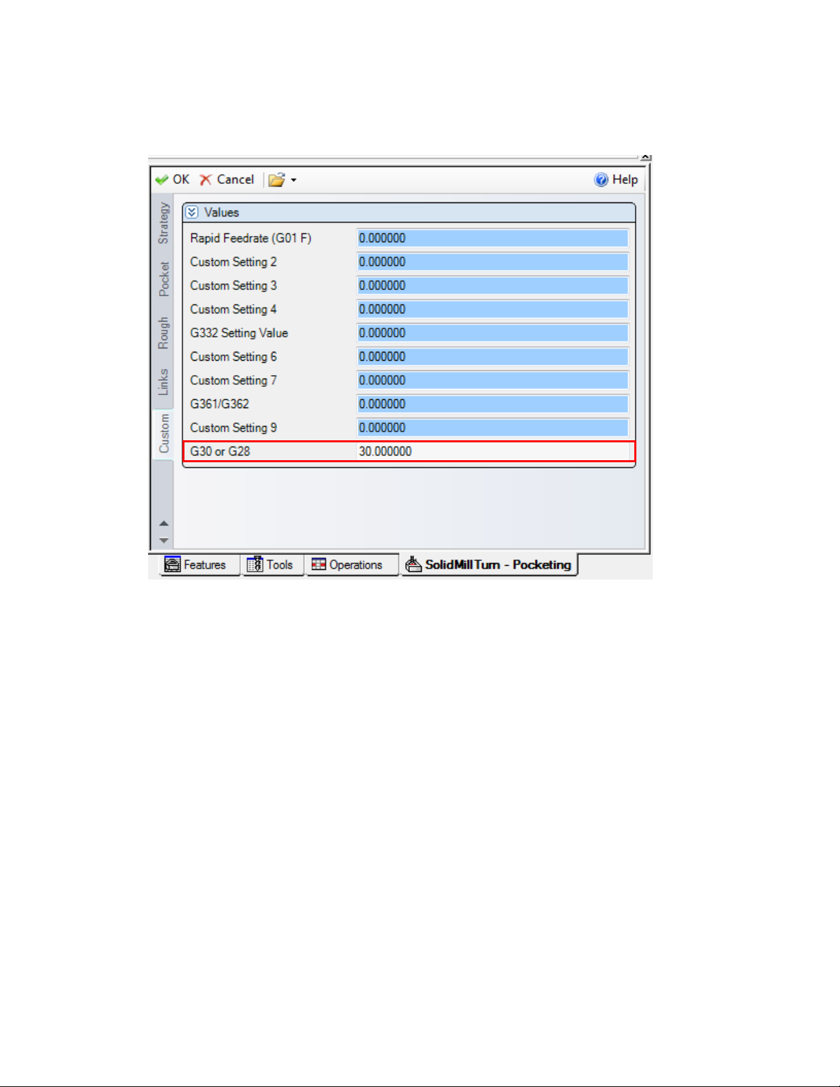
This can also be set within a specific operation page as well as shown below with the “G30 or
G28” (Operation Custom setting 10)
35
Page 43
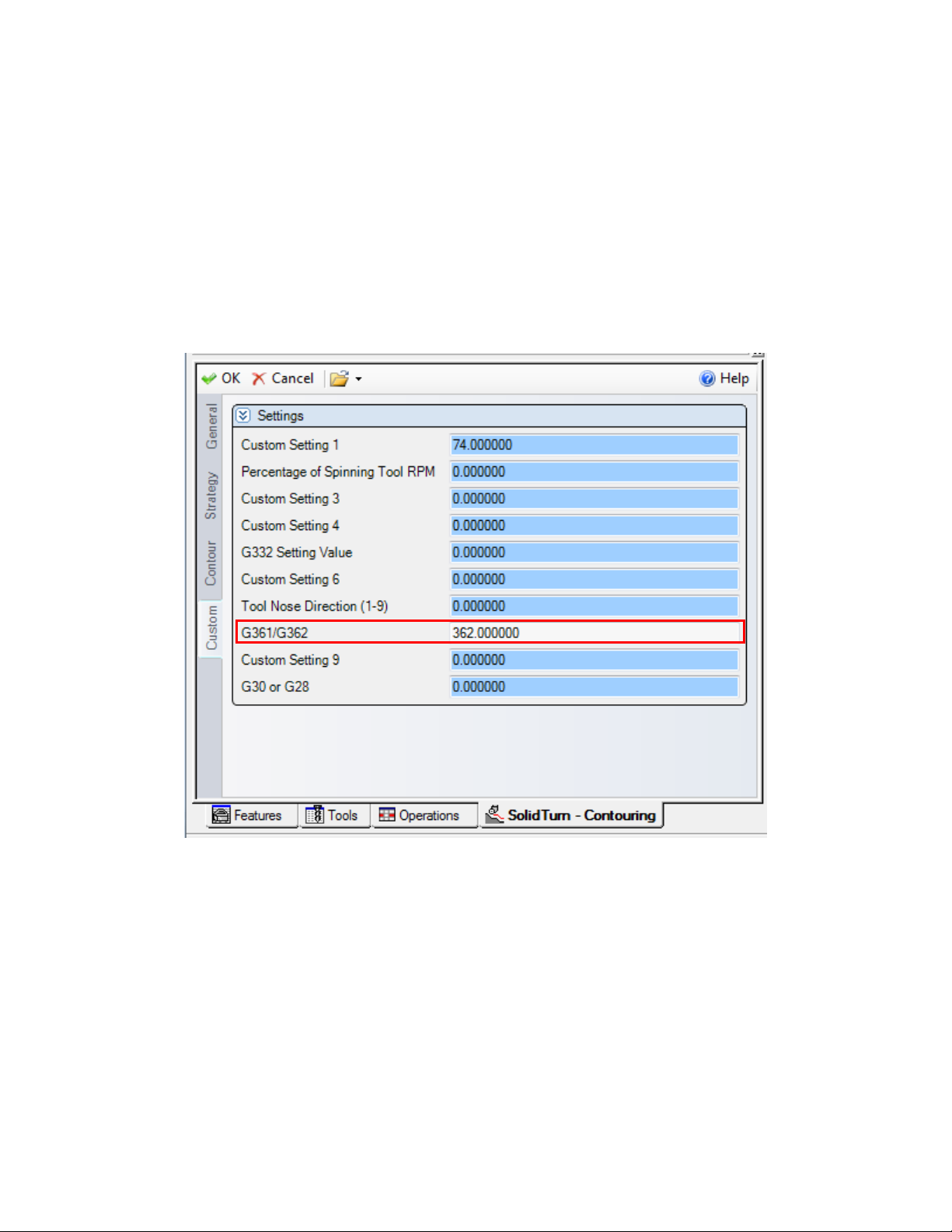
5.5. G361/362 Tool Change Command Setting
For the Upper Turret of the NT-SZ machine, it is possible to output the tool change command
with either G361 or G362 (via 4th zero point).
For any operation where the part is being held by only one spindle (where G361 is standard),
navigate to the Custom Settings tab, and to output G362 instead of G361, set the “G361/G32”
field to 362 (Operation Custom Setting 8). If any value other than 362 is input, G361 will be
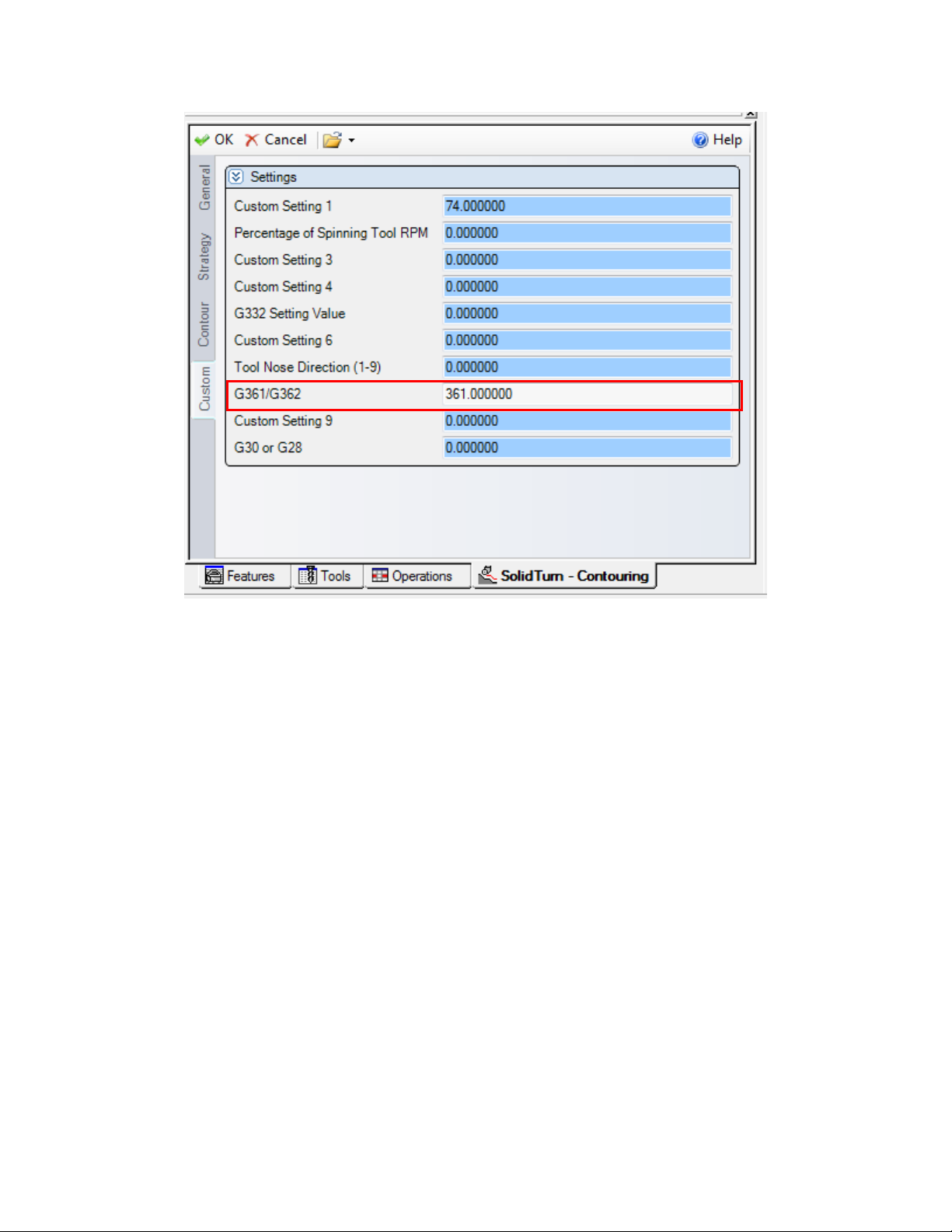
output in the NC Code.
For operations where both spindles are holding the part (simultaneous machining), the G362 tool
change call is standard. If the user would like to instead output G361, set the “G361/G32” to 361.
If any value other than 361 is input, G362 will be output in the NC code.
36
Page 44
37
Page 45
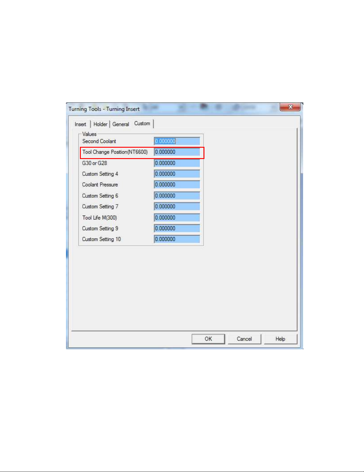
5.6. Tool Change position
NT-S 6600 machines have the ability to change the tool change position. This is done with an R
value on G361/G362 line. This can be programed by setting the desired position number into the
Tool Change Position (Custom Setting 2) field.
38
Page 46
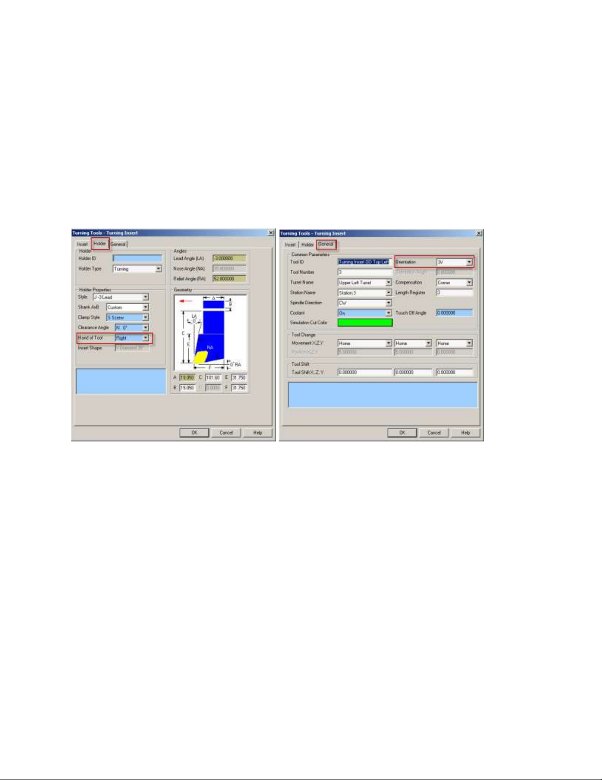
6. Spindle Direction, Speed, and Feedrate
6.1. Turning Spindle Direction and Milling Tool Spindle
Direction
For turning operations using a cutting insert (Roughing, Balanced Roughing, Contouring,
Grooving and Threading), the spindle direction will automatically be computed by the post
processors and will output the correct M-code (M03, M04, M203 or M204) based on the hand of
the tool on the holder and the orientation of the tool. The field Spindle Direction on the General
tab has not effect on the output.
Custom Turning tools do not have the option to select if the tool is a right or left hand tool. In
this case we use the Holder Thickness field. If this value is a positive value the post will know
this is a left hand tool, if it is a negative value it is a right hand tool.
39
Page 47
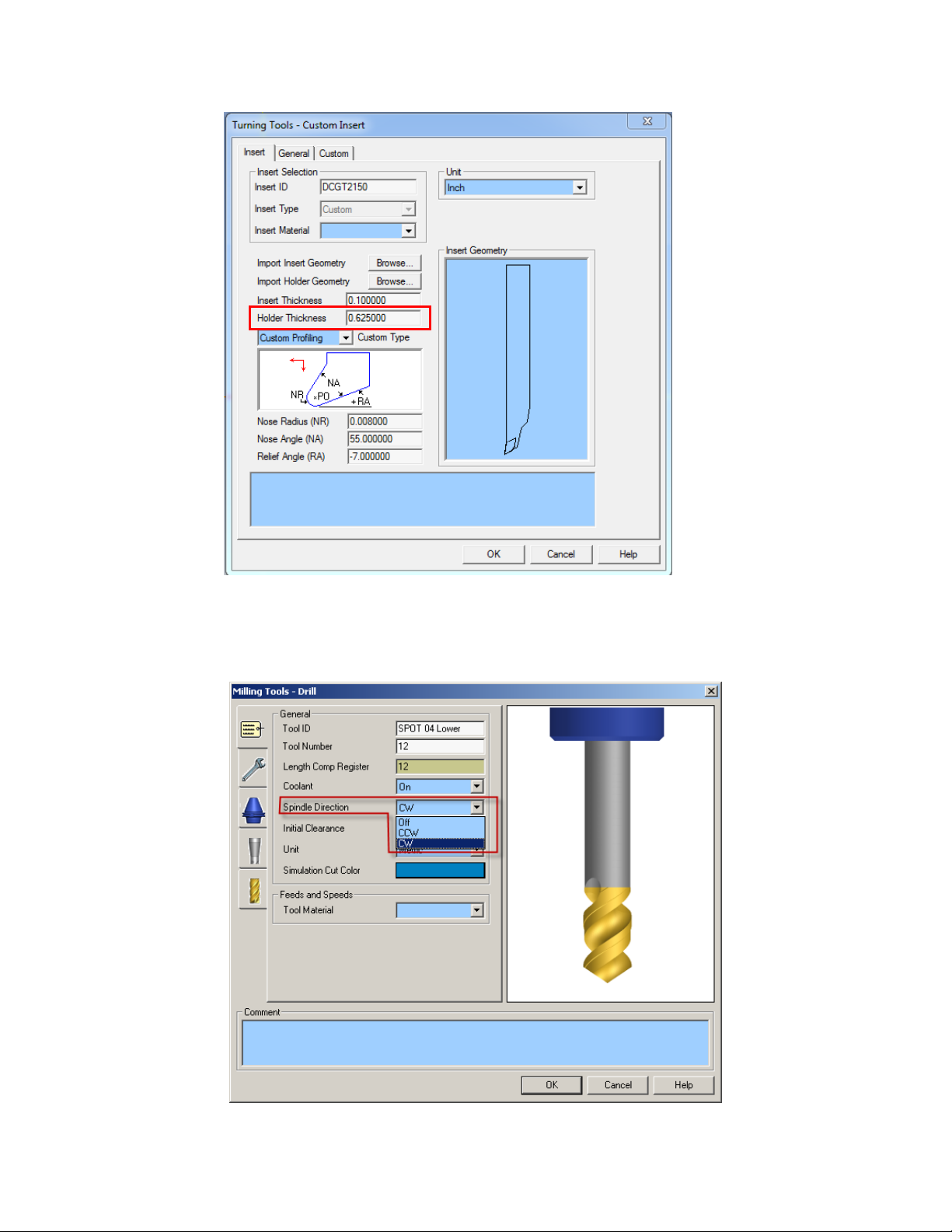
For the turning Drilling and milling operations, the turning spindle direction or milling tool
spindle direction is specified by the Spindle Direction pull down on the first tab of the tool page.
40
Page 48
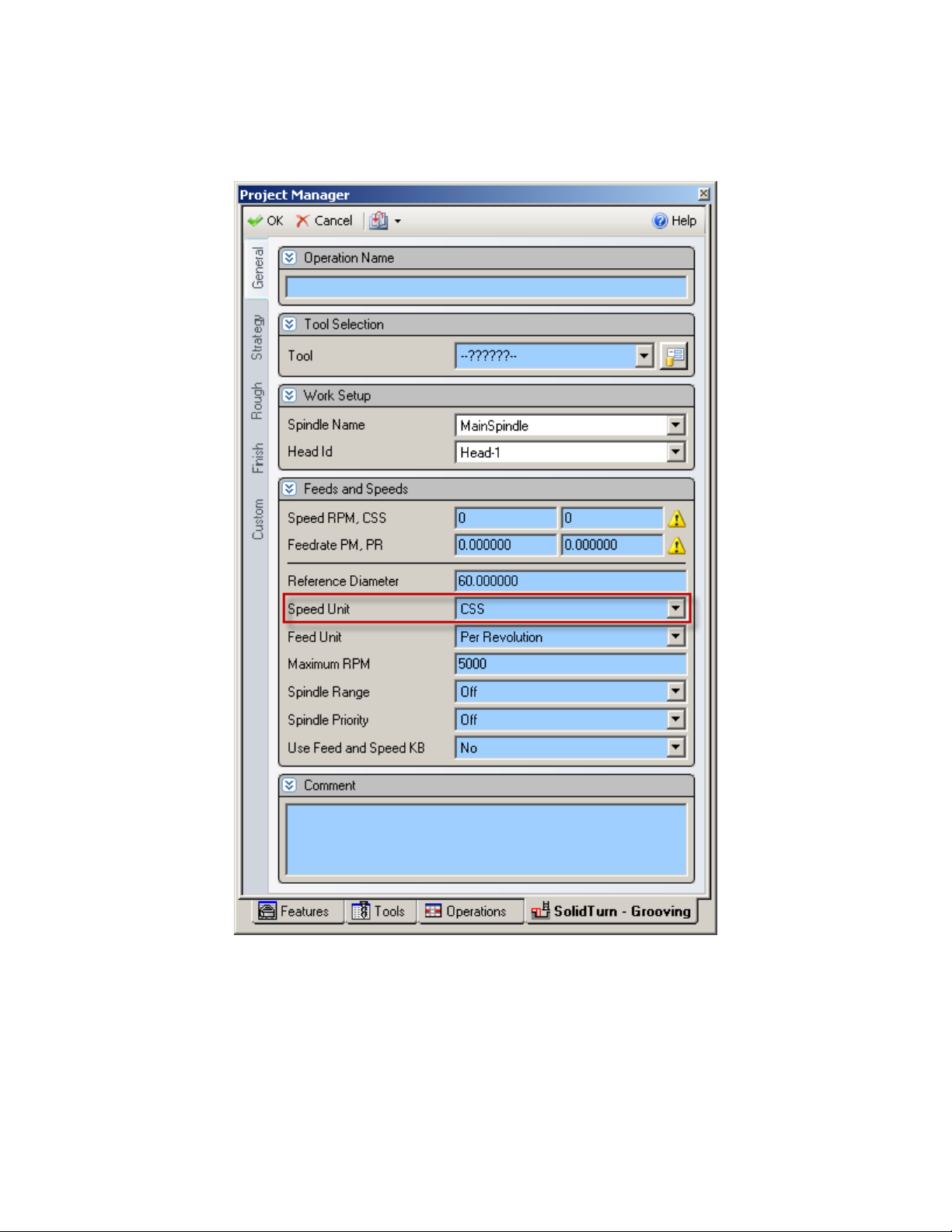
6.2. Spindle Speed output for CSS Unit
On a turning operation page, if you choose to output the turning spindle speed in the unit CSS
(Constant Surface Speed), a warm up speed will first be output with the G97 code before the first
positioning move. The speed value is computed at the first diameter from where the CSS
command will be turned on. Next, after positioning the tool, the CSS tuned on by the output of
G96 S. The cut is done and finally, at the last diameter, the CSS is cancelled by the output of
G97 S with S computed at the current last diameter.
41
Page 49
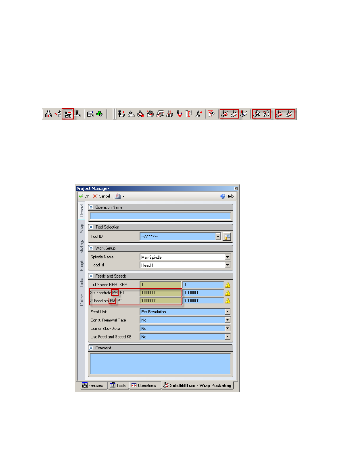
6.3. Feedrate for 4-axis Milling Operations
For Wrap Pocketing and Wrap Contouring operations with Cylindrical Interpolation set to No or
Rotary Face Pocketing and Rotary Face Contouring operations with Polar Interpolation set to
No, a rotary feedrate will be computed by the post processor, based on the linear and rotary (Caxis) moves of the cut.
This computation is necessary since two types of feedrate are involved for 4-axis wrap cuts:
linear feedrates (linear moves along XYZ) in inch/min (or mm/min) and rotary feedrates (angular
moves around the C-axis) in deg/min.
In ESPRIT, when programming such operations, simply enter the desired XY and Z PM (per
minute) feedrate values. The post will then, based on these values; compute the correct 4-axis
feedrate
.
42
Page 50
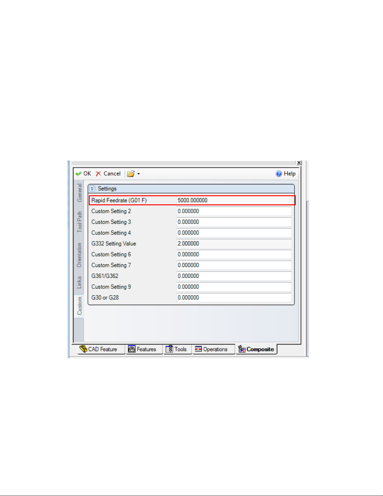
6.4. Feedrate option for rapid moves in 5 axis operations
At times it is better to program a high feedrate move rather than rapid moves (G00). This is
particularly true in 5 axis mode.
In order to output a G01 and a high feedrate instead of a G00 rapid type move in a 5axis
operation set the “Rapid Feedrate” filed to the desired feedrate for the rapid moves within the 5x
operation.
If this value is left 0 G00 will be output for the rapid moves.
This setting is only active in the operation programed. If you want to use the G1 F option for
multiple operations you will need to set this in each operation.
6.5. Turning on AI Contour Control
This function is provided for high-speed, high-precision machining. It enables suppression of the
delays in machine movement during acceleration/deceleration that become larger as the feedrate
increases, and machining profile errors are reduced as a result.
To use the AI Contour Control, the user must first select which cutting mode they would like to
use for an operation. There are four cutting modes possible with AI contour control. They are:
43
Page 51
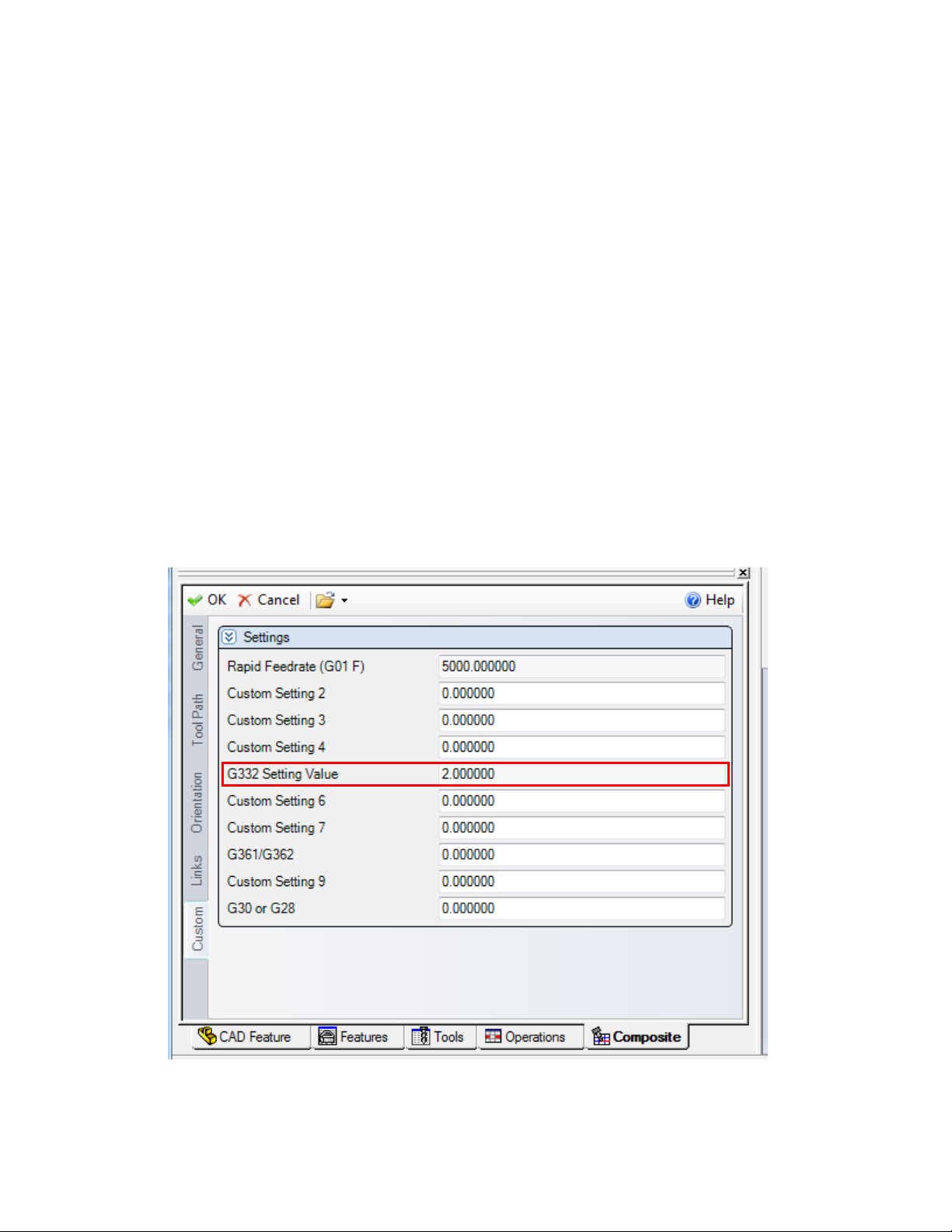
R1: Time Priority Mode
R2: Middle Mode
R3: Accuracy Priority Mode
R4: Custom Mode
For further details about each of these cutting modes, please see the NT Programming Manual.
Once the user has selected which cutting mode is appropriate for a given operation, navigate to
the “Custom” tab of the operation and in the “G332 Setting Value” field (Operation Custom
Setting 5), enter a one (1), two (2), three (3), or four (4) to select R’s 1-4 respectively. If the
G332 Setting Value is zero (0), AI Contour Control will not be activated.
Once this setting has been changed, click OK to exit the operations page.
NOTE: The user must set Operation G332 Setting Value for EVERY operation that they would
like to use AI Contour Control with. ESPRIT will automatically output the corresponding code
to turn off this function at the end of each operation.
44
Page 52
7. 5-axis Simultaneous Milling Options
7.1. Introduction
When programming a simultaneous 5-axis operation in ESPRIT for the NT machine, there are
three options for the format of the output code:
Fixed Type1 Mode (G43.4, XYZ BC WKP=1)
Rotate with Part Type1 Mode (G43.4, XYZ BC WKP=0)
Rotate with Part Type2 Mode (G43.5, XYZ IJK WKP=0)
When cutting in a 5-axis simultaneous mode on an on the sub spindle of an NT1000 machine, the
BW axis MUST be at BW0.
The post supports 5-axis operations in the upper head, even if the operation is only used for wrap
type machining.
7.2. Definitions
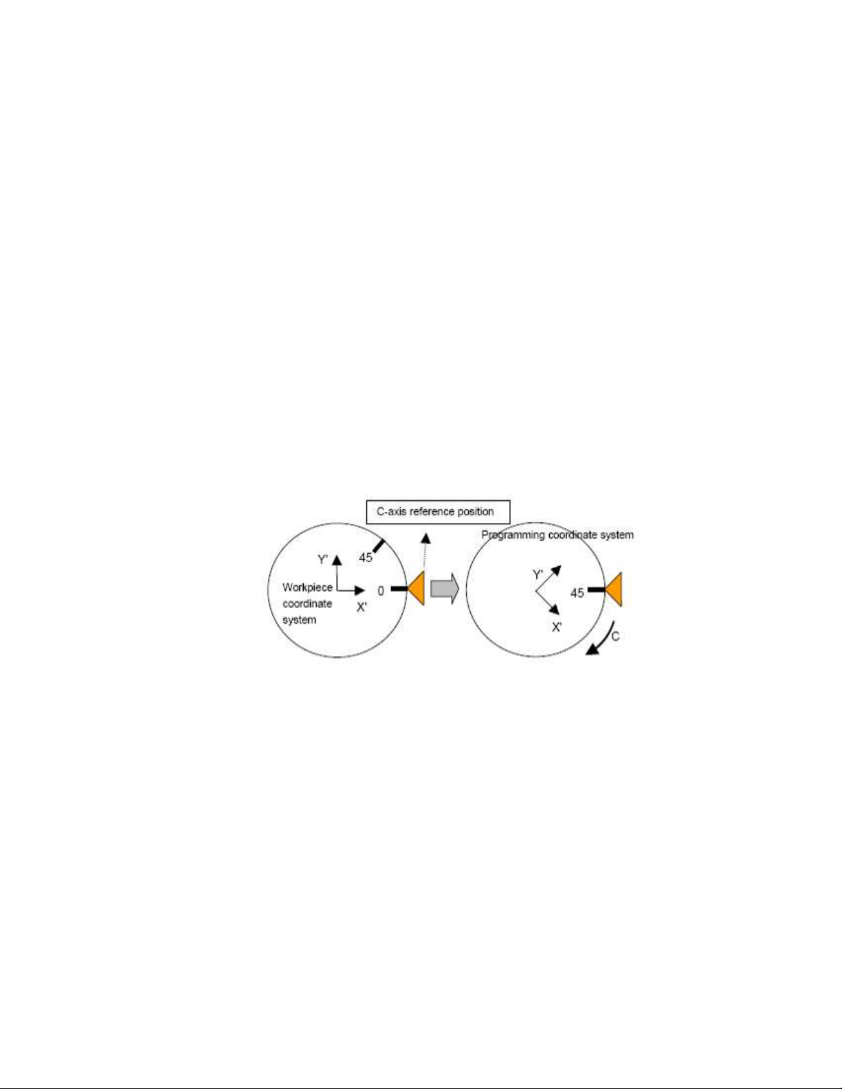
7.2.1. Rotate With Part
o Coordinates are output relative to the table/spindle. The coordinate system is
attached to the work piece and rotates with the part.
o After the RTCP command is specified, the workpiece coordinate system that is
fixed on the table at that point in time becomes the programming coordinate
system. Thereafter, the programming coordinate system rotates as the table turns
around.
o The coordinate system does not rotate with the tool head.
o Type1 outputs code with a G43.4 and coordinates expressed with XYZ for linear
axes and ABC for rotary axes (See sample code below).
o Type2 outputs code with a G43.5 and coordinate expressed with XYZ for linear
axes and IJK for rotary axes (See sample code below).
45
Page 53
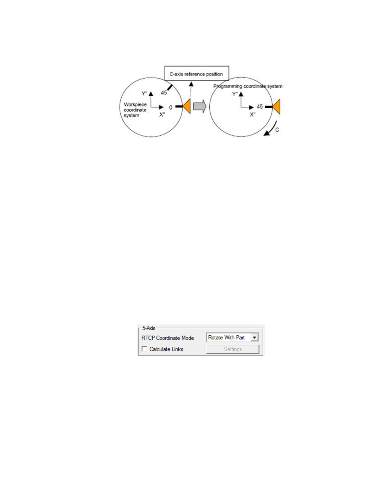
7.2.2. Fixed
o Coordinates are output relative to the current work piece origin (local work
coordinate in ESPRIT). In this case, the programming coordinate system does
NOT rotate as the table turns around but remains fixed on the workpiece
coordinate system.
o This mode changes the coordinates output by the postprocessor when there is at
least one table rotary axis.
o For a tool/tool rotary axis configuration, this mode has no effect. With the Rotate
With Part option, the XYZ coordinates in the NC code are similar to coordinates
output for a machine with two rotary axes on the milling head (tool/tool
configuration).
o Type1 outputs code with a G43.4 and coordinates expressed with XYZ for linear
axes and ABC for rotary axes.
7.3. Operation Types
7.3.1. RTCP Type 1 WKP=0 (G43.4)
ESPRIT Machine Setup ‘RTCP Coordinate Mode’ must be set to Rotate With Part.
TCP Type must be set to “TCP Type 1” in the Post Output Configuration Utility.
7.3.2. RTCP Type 1 WKP=1 (G43.4)
ESPRIT Machine Setup ‘RTCP Coordinate Mode’ must be set to Fixed.
TCP Type must be set to “TCP Type 1” in the Post Output Configuration Utility.
46
Page 54
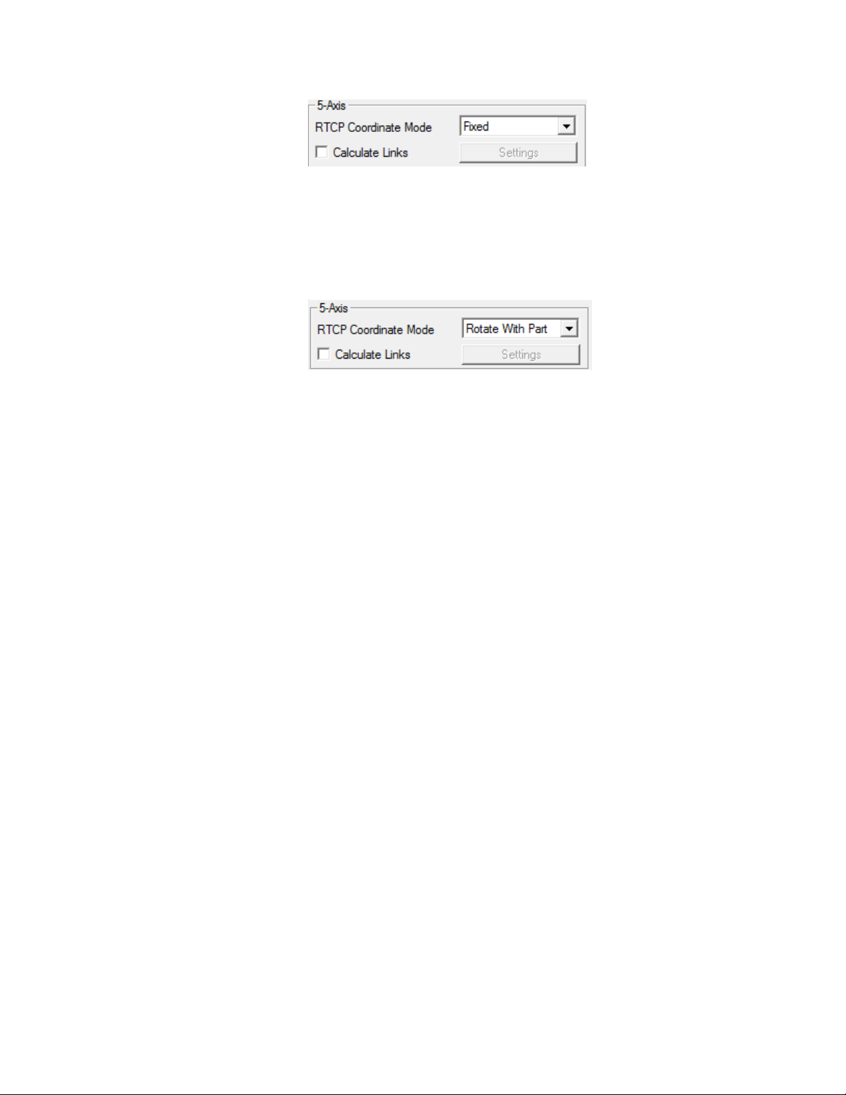
7.3.3. RTCP Type 2 WKP=0 (G43.5)
TCP Type must be set to “TCP Type 2” in the Post Output Configuration Utility as well as
‘RTCP Coordinate Mode’ must be set to Rotate With Part on the Machine Setup\General Tab
.
47
Page 55

1
2
7.4. Additional Information
Machine Parameter
The following parameters need to be set on the Mori Seiki NT-SZ machine before performing 5axis machining:
1. G43.4 XYZBC WKP=1 -> 19696-bit5=1
2. G43.4 XYZBC WKP=0 -> 19696-bit5=0
3. G43.5 XYZIJK WKP=0 -> 19696-bit5=0
4. 19741 =Max. B-pos.
5. 19742 =Min. B-pos.
NOTE that you may only choose ONE RTCP mode for an entire ESPRIT file.
To turn on RTCP Mode navigate to the General tab and to the section called “RTCP” and set this
to “Yes”. You must perform this for each 5-axis operation that you create.
48
Page 56
8. Simultaneous Turning Operations: Turning on the same
spindle with two turrets
8.1. Balance Roughing Cycle
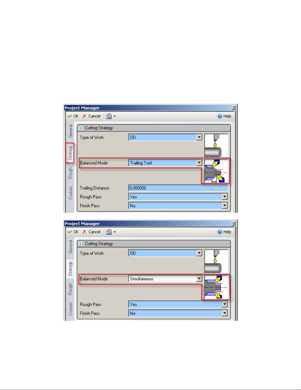
When programming a Balanced Roughing cycle, you have the choice between two different
balanced modes:
Trailing Tool: there is a user defined trailing distance between the two inserts.
Simultaneous: the cut is mirrored between the turrets, the feedrates can be doubled.
For the Trailing Tool balanced mode, a wait code (soft sync) will be output in between each
pass. For the Simultaneous balanced mode, the Balanced Cut Mode (G68) will be turned on on
49
Page 57

both involved heads and will be canceled at the end of the cut by the Balanced Cut Mode Cancel
code (G69).
The spindle speed will only be output in Head 1 (B-axis), not in Head 2.
50
Page 58
8.2. Other Turning Cycles
When two heads are cutting at the same time on the same spindle, the spindle command of a
head can override the spindle command of the other head.
The head with the longest operation must have the control of the spindle speed.
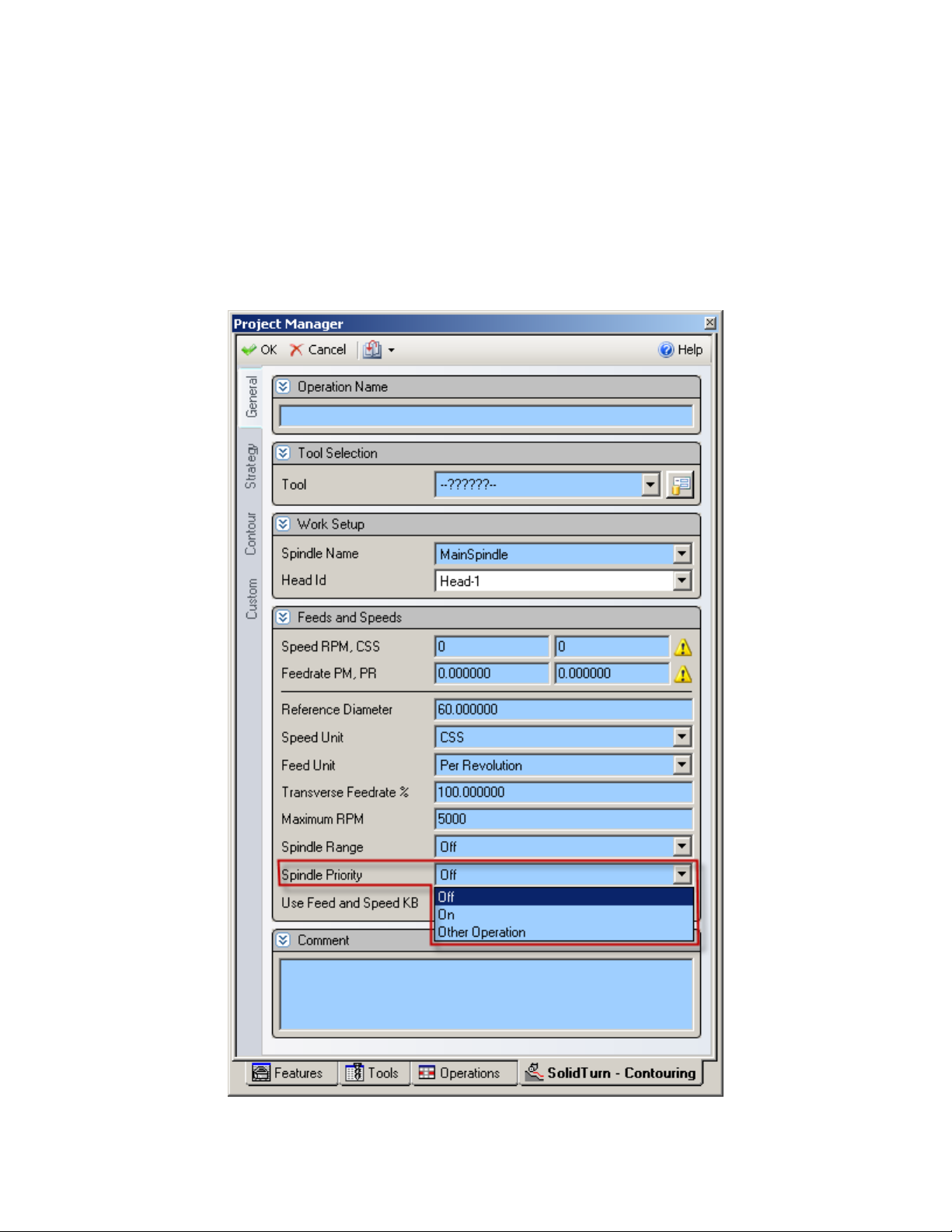
The head controlling the spindle and the head “slave” are set on the operation page of turning
operations, using the Spindle Priority setting:
51
Page 59

Set Spindle Priority to:
On to output the spindle speed (this head is controlling the spindle)
Other Operation: the other head is controlling the spindle and the spindle speeds are
output as shown in Machine Parameters section “Under Block Skip Methods”
Note: If using one of the block skip options make sure to activate the appropriate block delete
function on the control.
52
Page 60

9. Park Operation
9.1. Introduction
The park operation can be used to move either head to any location within the machine travels.
The park operation is most often used in the lower turret to avoid collisions between the B axis
head on the lower turret when working on the face of the part with the upper head at B+/- 90
degrees, when transferring parts from spindle to spindle, doing bar pull operations with the sub
spindle or part release operations.
With the Park cycle of ESPRIT, you will have different possibilities to park a tool located on
head 1 (or 2 for lower turret configurations). It is a great way to park a tool above a spindle to a
clearance position, so you can for example freely machine on the same spindle with another
turret for lower turret configuration machines. You can also send a tool home along the X, Y (Yaxis specifications only) and/or Z axis. You finally can park the turret to its far most left position
(left or right) or anywhere in-between using the machine work coordinate system (G53).
The NT1000 machines also use the park operation to position the A axis (Sub spindle) and BW
axis allow for more clearance when working on the main spindle with the B axis head.
When using the Park operation with the upper head, the Position type park modes are not
supported as the simulation will not match the machine movements. The Home and Machine
modes are fully supported.
In addition the B axis may also be parked with the park operation. Parking the C axis is not
supported by the post at this time..
When parking the lower turret, all modes (Position, Home, and Machine) are supported.
9.2. How to park a tool
On the Park tab of the Park operation page, using the Park Position X, Y & pull-downs and
fields, you can set how and where you want to park your tool.
53
Page 61
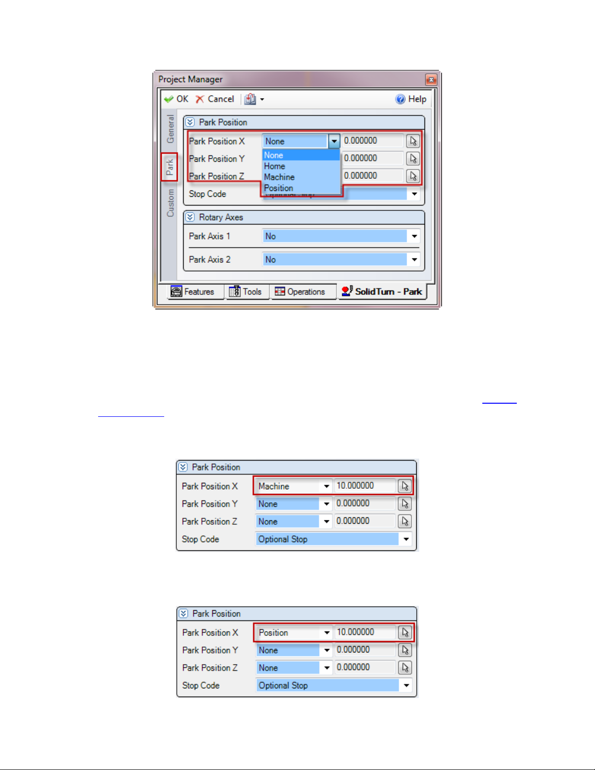
Set Park Position X, Y or Z to:
None: The tool will not move along the selected axis. If you set for example Park
Position X to None, the tool will not move along the X-axis when going to the park
position.
Home: The tool will be sent to the machine zero point with G28 along the selected axis.
Note that second home position G30 can be output instead of G28, please see part Second
home position section for additional information.
Machine: The tool will move along the selected axis in the machine work coordinate
(G53) to the specified position in Position X, Y, Z fields.
Position: The tool will be parked at the specified position in Position X, Y, Z fields at
rapid traverse rate (G00). Position mode is only supported by the lower turret.
54
Page 62
Note: The X; Y & Z positions entered in ESPRIT are absolute in YZX. So the post processor
will compute and output the correct values from this absolute position based on the turret, tool
and the spindle (work coordinate) in use.
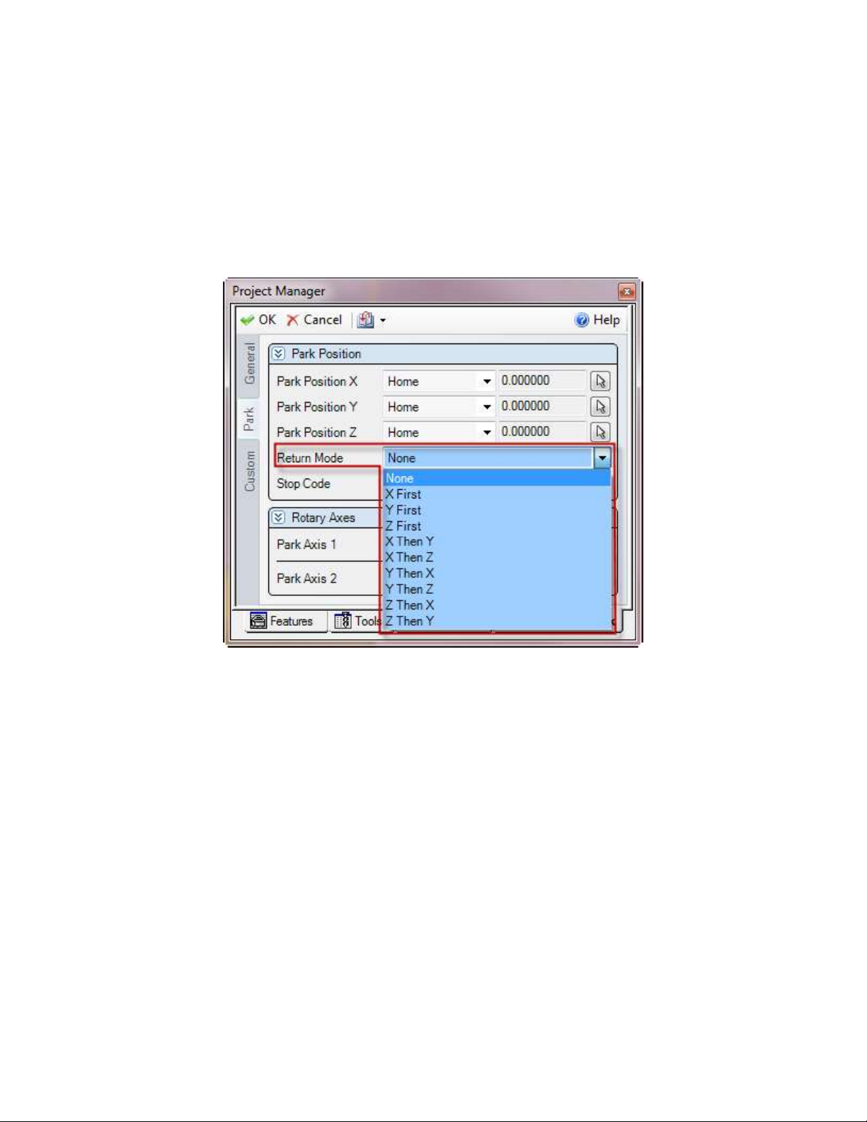
Once your tool movements correctly defined, you will be able to set the Return Mode. It controls
how the axes move to the park position. This setting is available only when at least 2 axes are
allowed to move during the park.
The different existing Return Modes are:
None: All axes move directly to the park position. All axes allowed to move will move
together.
X First: The X axis is moved first to Park Position X. Then all other axes move in a
second step.
Y First: The Y axis moves first. Then all other axes move together.
Z First: The Z axis moves first. Then all other axes move together.
X Then Y: X moves first, then Y, then Z.
X Then Z: X moves first, then Z, then Y.
Y Then X: Y moves first, then X, then Z.
Y Then Z: Y moves first, then Z, then X.
Z Then X: Z moves first, then X, then Y.
Z Then Y: Z moves first, then Y, then X.
The options available for Return Mode depend on the axes selected for movement and their
positions type (None, Home, Machine or Position). See the examples below:
55
Page 63
Example 1:
If Park Position X is set to Home, Park Position Y set to None and Park Position Z set to
Home: the choices for Return Mode become None, X First or Z First.
Example 2:
If Park Position X is set to Home, Park Position Y set to Home and Park Position Z set to
Machine: the choices for Return Mode become Z First, X Then Y, X Then Z, Y Then X, Y
Then Z, Z Then X or Z Then Y.
Since movements in machine work coordinate system (G53) cannot be output in the NC
code on the same line as movements home (G28), ESPRIT is filtering the forbidden
combinations. These combinations will always have Z movement output on its own line in
the NC code.
Example 3:
If Park Position X, Y & Z are all set to Home: all Return Modes become available.
Note that If your machine does not have a Y-axis on the lower turret, any Y-axis movement
programmed with the Park cycle will be ignored.
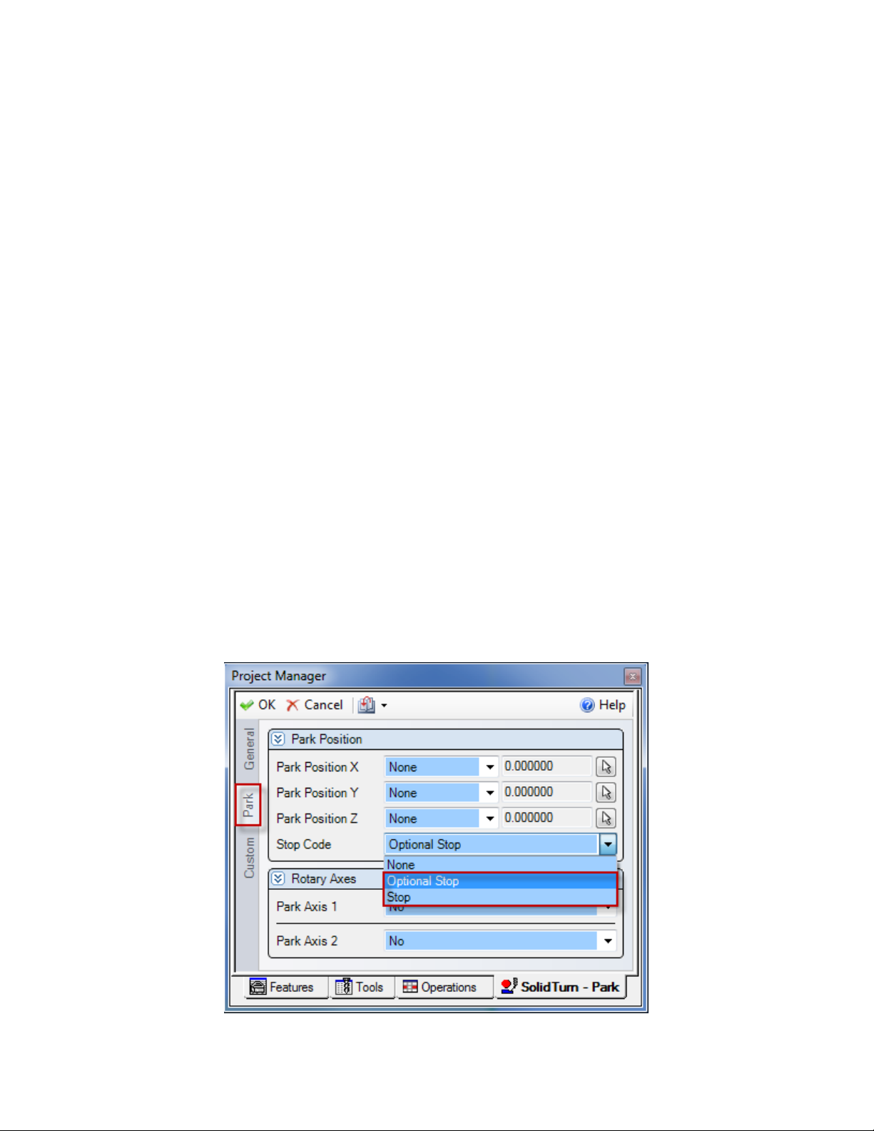
9.3. Stop Code Options
On the Lathe Park tab of the operation, if you set Stop Code to Stop, a Program Stop Code
(M00) will be output. If you set Stop Code to Optional Stop an Optional Stop Code (M01) will
be output. If ether Optional Stop or Stop Code are used, the post will repeat the tool change
information after the park operation to ensure all the necessary commands are active for the next
operation.
56
Page 64
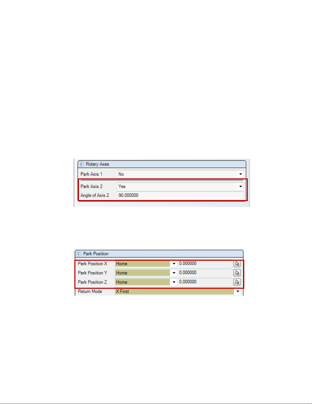
9.4. Setting the B axis angle
If parking the upper head, the angle of the B axis can be controlled by the park operation if
desired. To do this set the Park Axis 2 to Yes and enter the desired angle into the Angle of Axis 2
field.
If the park operation makes a tool change, the B axis will always move to the position of the B
axis in the Rotary angles properties (normally B0) even Park Axis 2 field is set to No. Therefore
if the park operation is making a tool change it is best to set the Park Axis 2 field is set to Yes
and set the desired B axis angle.
If the park operation does not make a tool change the B axis will only be moved Park Axis 2
field is set to Yes, otherwise the B axis will be left at its current angle.
If you park the B axis and you select the G53 Option the machine will move the Z axis home
(G29/G30 W0) prior to moving the B axis, then move to the G53 position.
Note: Parking the C axis (Park Axis 1) is not implemented in the NT posts.
In Addition, since the B axis can only be moved if the XYZ axis are at the home position, the
XYZ axis must all be set to HOME if the B axis is going to be moved by the park operation.
If you would like the XYZ axis to be at a different location after the B axis is positioned, you
will need to do this in a second park operation.
57
Page 65
9.5. Park head/ turret to its minimum travel position (G53)
Moving the head/turret to the far left position by setting the appropriate locations in the park
operation or you can enter in a value in to the park op shown below in the park operation. If this
is done the simulation will match the NC code.
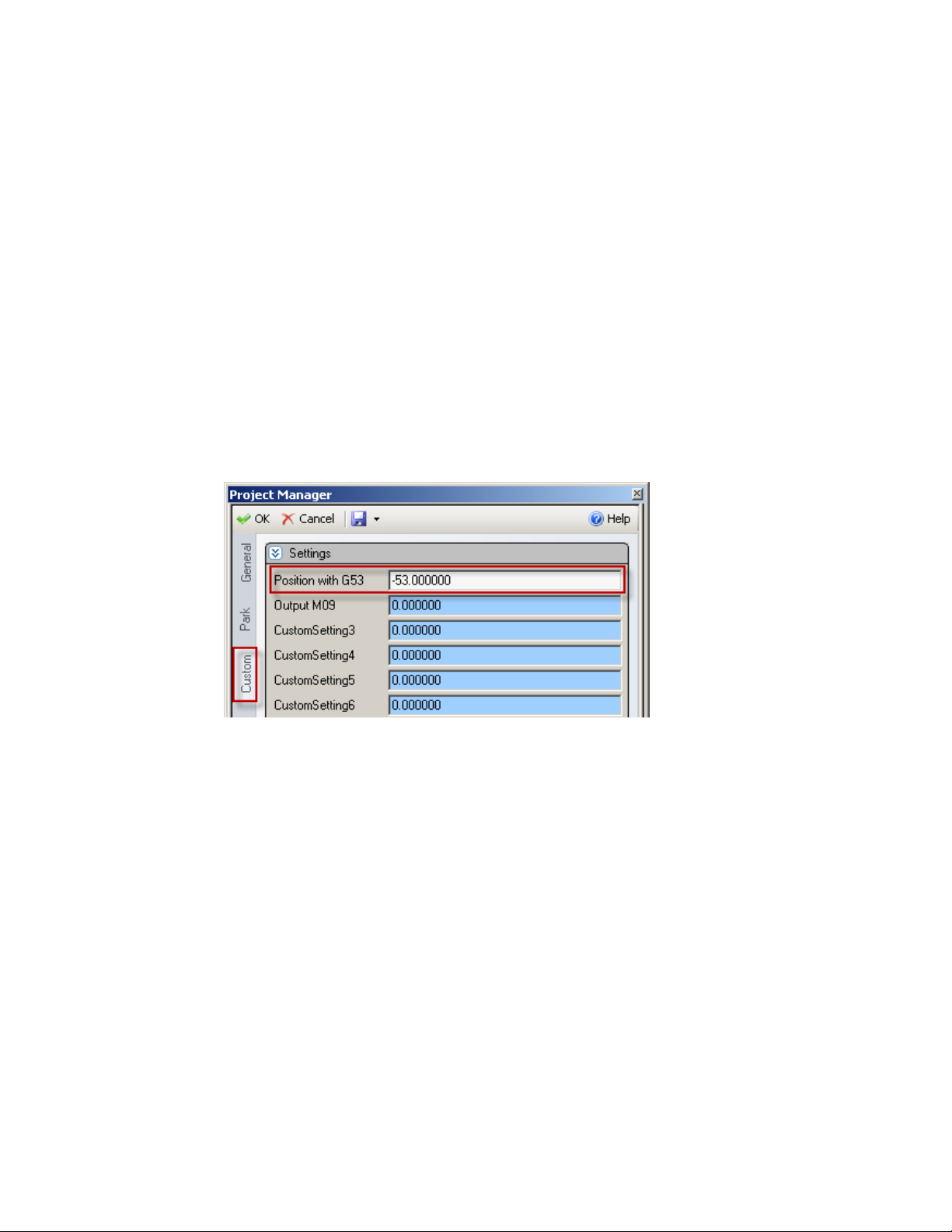
Prior to ESPRIT 2012 we did not have the ability to match the simulation with the NC code so
we provided a method of parking the head/turret by putting a value of “-53” in Position with G53
field (Custom Setting 1) of the Park operation.
If you set Position with G53 to -53, the active turret will be parked to its left maximal travel
position regardless how the park operation is setup but simulation may not match the NC code.
This is the location in which the lower turret needs to be parked prior to a part transfer or part
release. If the Esprit file does not park the turret the post will park the turret before the transfer
or the part release.
58
Page 66
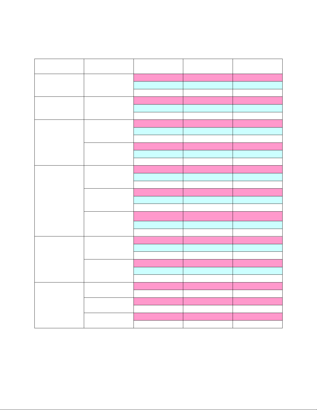
Machine Model
Bed Length
Head/Turret
Left position(mm)
Left position(inch)
1000
Head 1
G53 Z-230.
G53 Z-9.05
Lower turret
G53 Z-305.
G53 Z-12.008
2000
1500
Head 1
G53 Z-780.
G53 Z-30.7
Lower turret
G53 Z-751.
G53 Z-29.56
3100
3150
3200
500
Head 1
G53 Z-470.
G53 Z-18.5
Lower turret
G53 Z-470.
G53 Z-18.5
1000
Head 1
G53 Z-540.
G53 Z-21.25
Lower turret
G53 Z-485.
G53 Z-19.09
4200
4250
4300
700
Head 1
G53 Z-560.
G53 Z-22.04
Lower turret
G53 Z-505.
G53 Z-19.88
1000
Head 1
G53 Z-560.
G53 Z-22.04
Lower turret
G53 Z-505.
G53 Z-19.88
1500
Head 1
G53 Z-817.5
G53 Z-32.18
Lower turret
G53 Z-762.5
G53 Z-30.01
5400
1200
Head 1
G53 Z-670.
G53 Z-26.37
Lower turret
G53 Z-615.
G53 Z-24.21
1800
Head 1
G53 Z-970.
G53 Z-38.18
Lower turret
G53 Z-915.
G53 Z-36.02
6600
3000
Head 1
G53 Z-1575.
G53 Z-62.0
4000
Head 1
G53 Z-2075.
G53 Z-81.69
6000
Head 1
G53 Z-3075.
G53 Z-121.06
Minimum travel position values (in the machine coordinate system G53) for NT machine
configurations:
59
Page 67
Notes
That if the tool selected in the park operation is not the same as the previous tool the turret will
be sent to the tool change location, change the tool, then move to the park location.
The -53 option is now obsolete with the new AutoPark Addin, see the Setting up the park
operation with the AutoPark addin section below.
9.6. Park lower turret prior to a transfer (Z configurations only)
Once correctly setup, you can park the turret using the Park cycle (with G53) prior to a transfer.
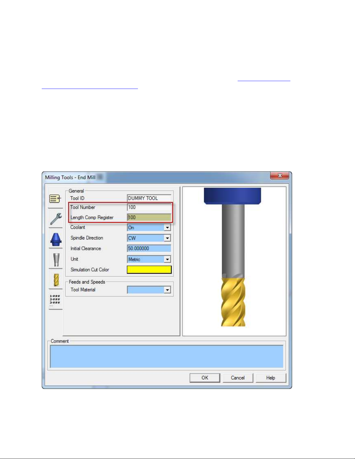
If you want to select a blank station on your turret for the park operation you will first need to
create a dummy tool on the turret, in the right station. Set the Tool Number to whatever you have
decided to use as the empty station and the Length Comp Register to 0.
Then, simply program a Park operation using this previously defined tool prior to the transfer
sequence. Note that since the tool call will be made without tool wear offset number, you will
60
Page 68
need to set Position with G53 to -53 (see section Park head/ turret to its minimum travel position
(G53) ) on the Park operation Custom tab. The turret will be parked using G53.
Note: Prior to a park operation the spindle is always stopped. After a park operation the post
will output a complete tool change section even if no tool change takes place after a park
operation. This is done to ensure all the necessary functions are re-started after a park operation.
9.7. Setting up the park operation with the AutoPark addin
The AutoPark addin is an alternative method of setting up the park operation to move the
Head\Turret to the minimum travel limits. The advantages of the addin is that it automatically
setups up your park locations of the head/turret for both correct NC code and simulation.
If the AutoPark addin has been run and has the turret parked at the AutoPark location, the -53
option in the “Position with G53” field (Custom Setting 1) will be ignored by the post.
If after you park the turret with the AutoPark addin you change a setting in the park operations
locations, the AutoPark addin will then reset its Park Turret Code field to “None” and the Park
operations positions or the -53 option will be used by the post.
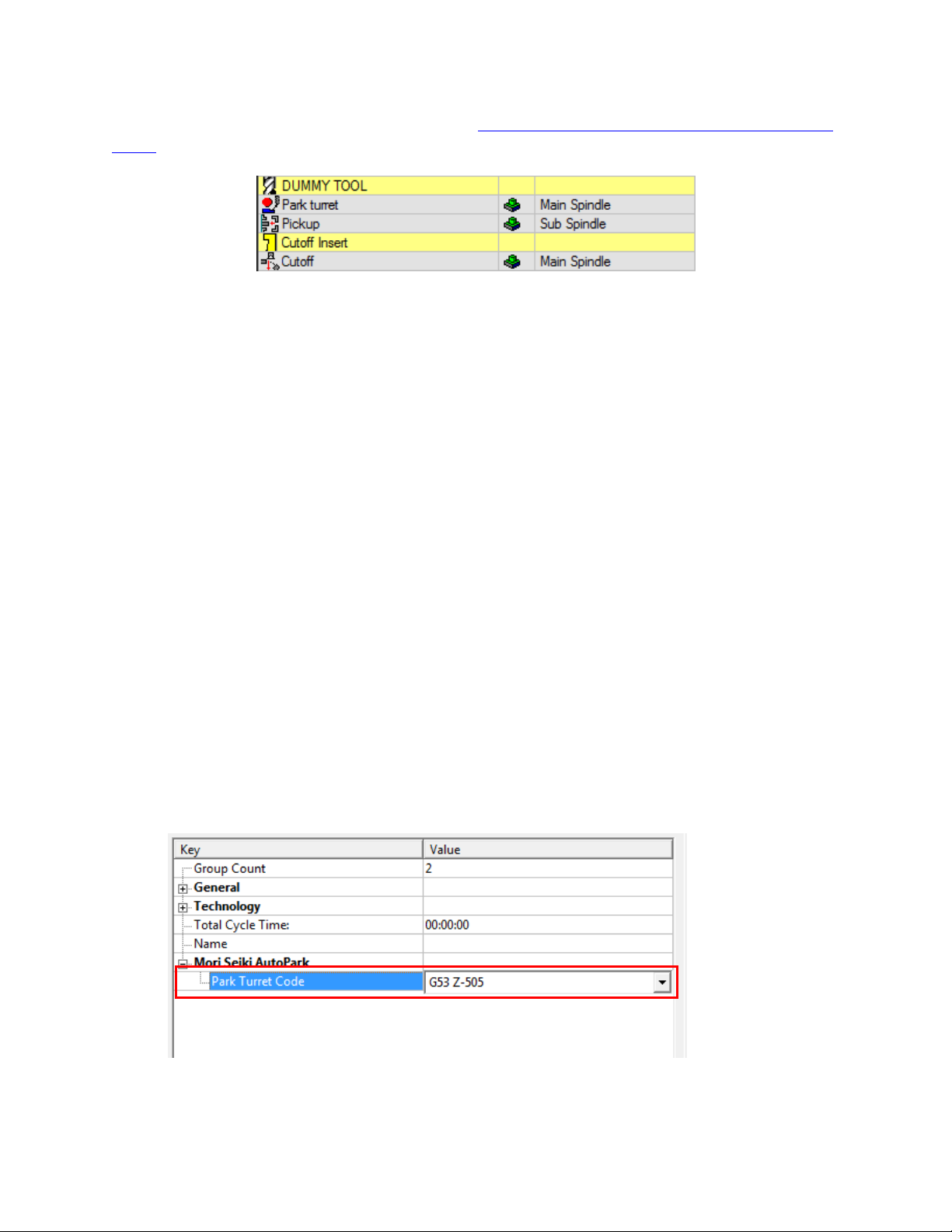
To use the AutoPark addin perform the following steps:
1. Create a park operation, select the tool/or Turret, Spindle as you would normally do
2. Do not set any values in the park tab for the park location of the XYZ axis
3. Press OK to create operation
4. Group park operation
5. Look in the properties dialog box and find the “Mori Seki AutoPark” heading
6. Press “+” to expend the fields under the heading
7. Select the Park Turret Code option in the pull down list.
61
Page 69
Workpiece
Transfer Utility
Icon
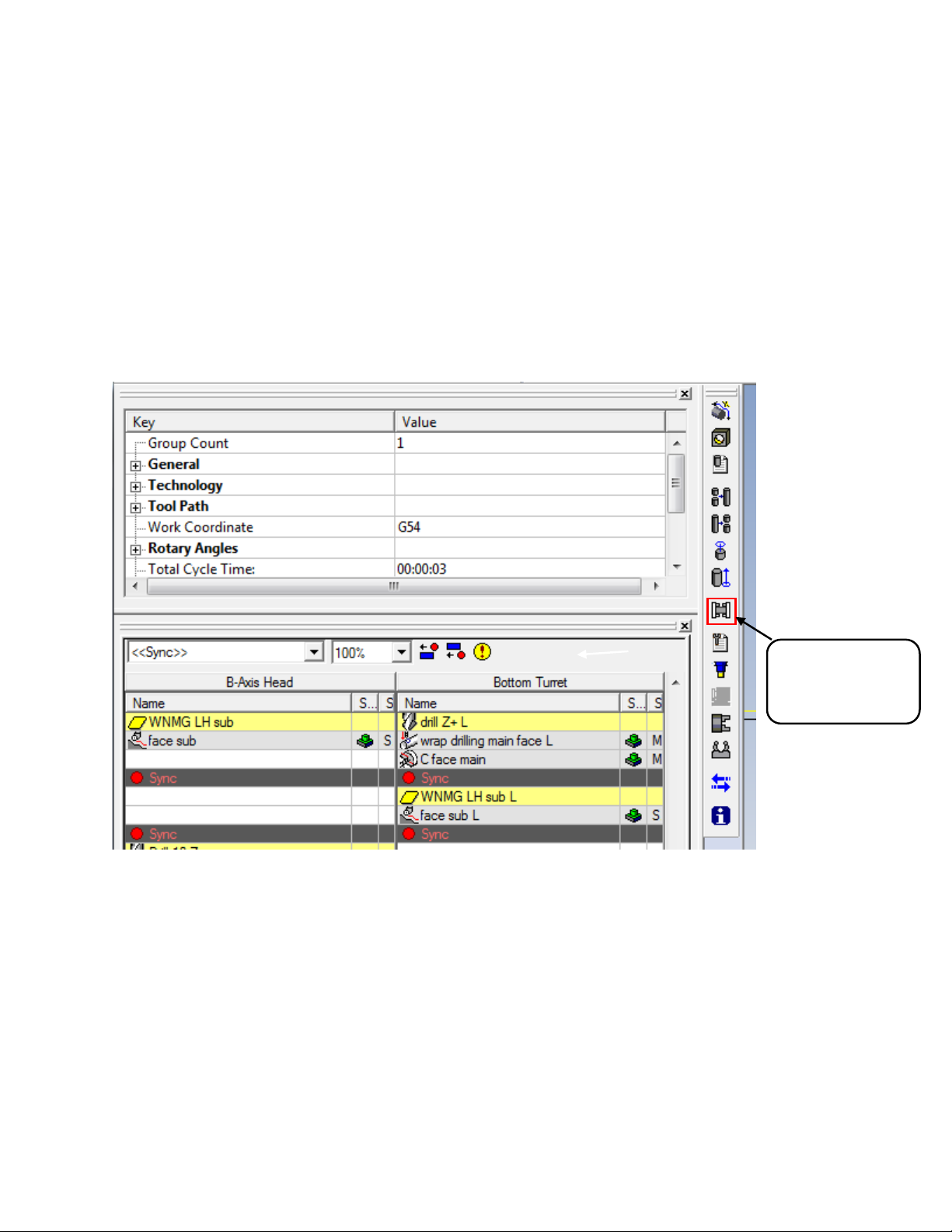
10. How to Program a Part Transfer
10.1. Introduction
The part transfers can be programed using the Mori Seiki Workpiece Transfer utility. This utility
streamlines the creation of the multiple operations used a typical transfers on the NT machines.
In order for the post to create the proper output for the part transfer there must be at least one
operation in the lower turret’s operation list, even if it is just a park operation.
The Workpiece Transfer Utility can be found on the Mori Seiki addin as shown below:
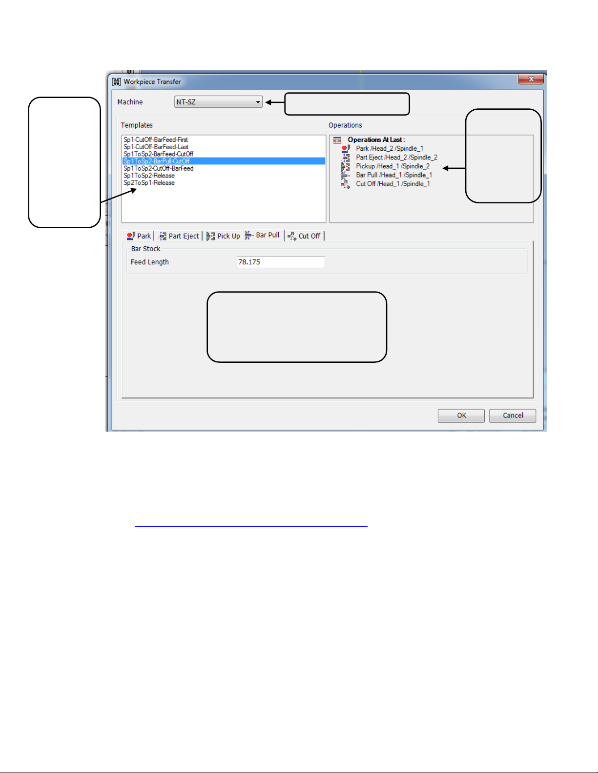
Selecting this Icon brings up the Workpiece Transfer dialog box. In the Workpiece Transfer
dialog box you will noticed that your machine type is selected automatically and the list of the
most common transfers are shown.
62
Page 70
Machine Type
List of
operations
created by
selected
transfer
Tabs for each operation with the
necessary settings
List of
transfer
types
available
in the
utility for
selected
machine
At this point select the transfer you would like to use and fill in the appropriate values and the
transfer will be created for you in the ESPRIT file.
Notes:
Below are a summary of each of the transfer types supported by the utility.
In the Operation Tabs in the Workpiece Transfer Utility section is a detailed expiation of
the settings in operation tabs.
The Workpiece Transfer Utility does not cover every situation yet. You can always
modify what has been created to suite your specific needs. If you find errors or missing
transfers please contact support and let us know so we can update and improve the utility.
If your machine type is not selected you are not using the correct Machine Setup file.
You will need to down load the latest machine setup file and update your ESPRIT file.
In addition if you do not see the list of transfers you have an installation problem and you
should contact support for help in resolving this matter.
63
Page 71
10.2. SP1-CutOff-BarFeed-First
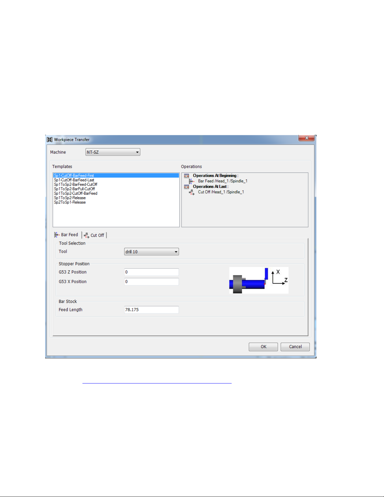
This transfer type really is not a transfer. This type of transfer would be used when only
machining on the main spindle.
The following operations will be created:
Bar feed by stopper on upper head at the top of the operation list
Cutoff Operation. On the upper head.
Refer to the Operation Tabs in the Workpiece Transfer Utility section for a detailed expiation of
the settings in operation tabs.
You may or may not need to park the lower turret before the bar feed operation to avoid collision
with the upper head. This can be done after the transfer is created.
64
Page 72
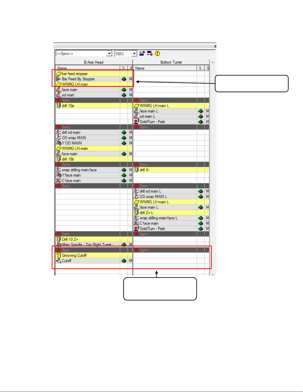
Added bar feed operation
Added Sync and Cutoff
Operation
Below is an example of a file after the transfer was applied to an NT-SZ file:
Note: This same option exists on all of the NT machines, non-lower turret machines will not
have the sync added, otherwise they are the same.
65
Page 73
10.3. SP1-CutOff-BarFeed-Last
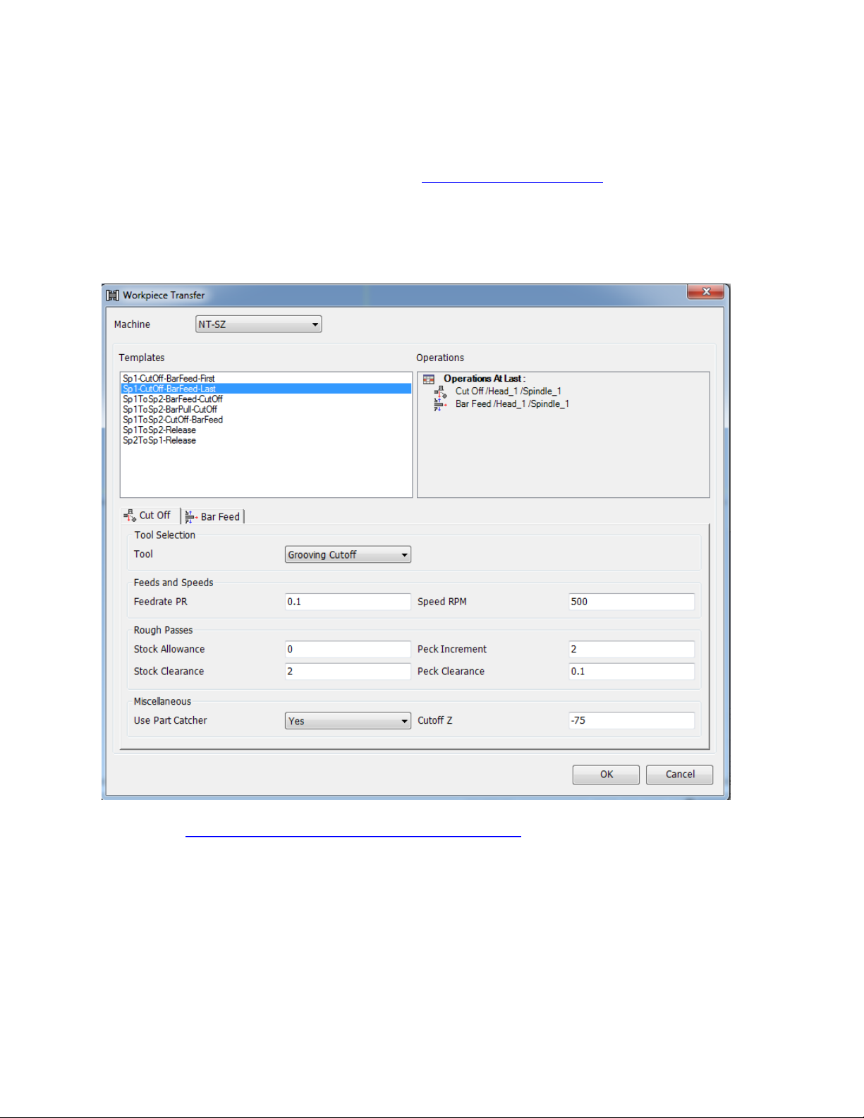
SP1-CutOff-BarFeed-last is very similar to the SP1-CutOff-BarFeed-First shown above.
The following operations will be created:
Cutoff Operation. On the upper head.
Bar feed by stopper on upper head
Refer to the Operation Tabs in the Workpiece Transfer Utility section for a detailed expiation of
the settings in operation tabs.
66
Page 74
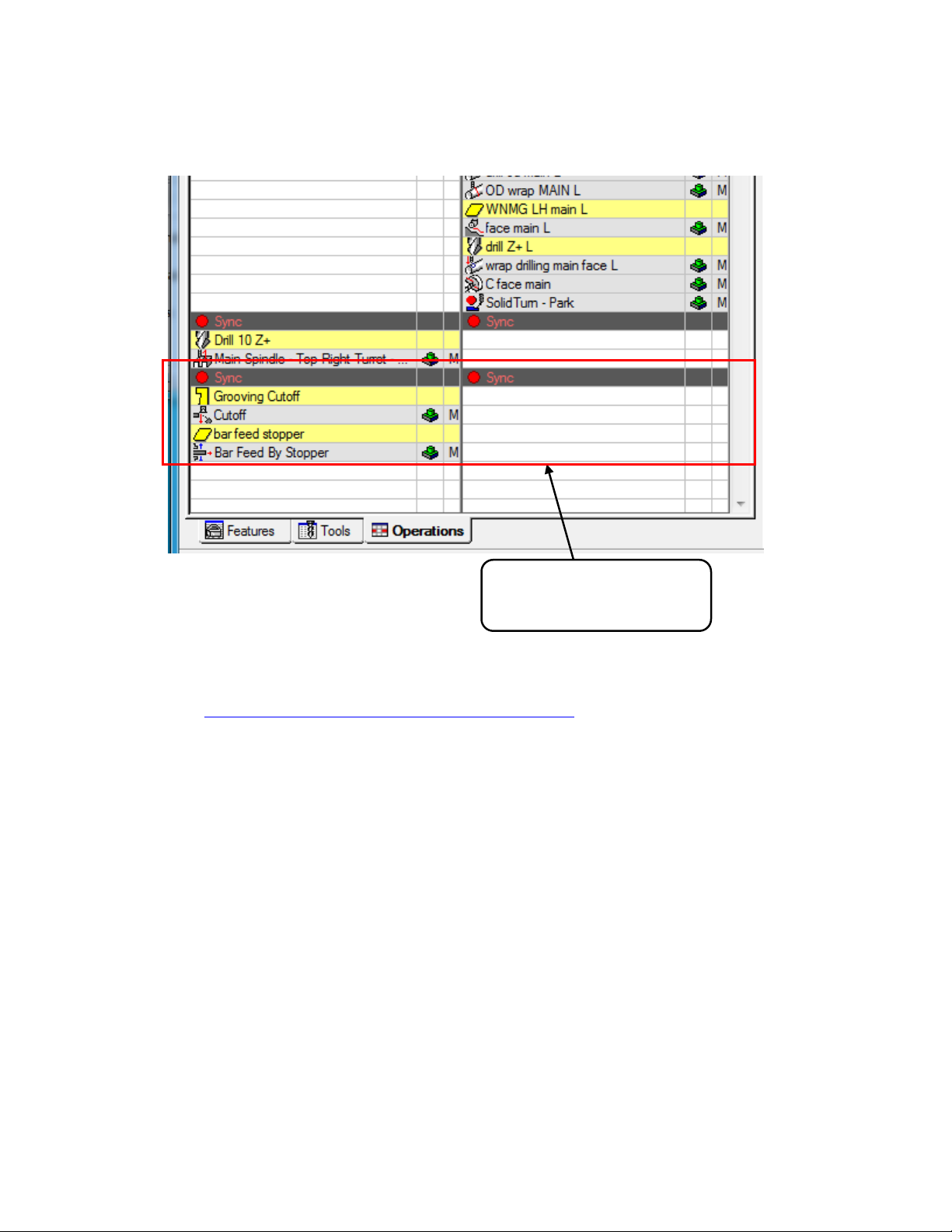
Added Sync Cutoff and
Bar Feed Operations
Below is an example of a file after the transfer was applied to an NT-SZ file:
Note: This same option exists on all of the NT machines, non-lower turret machines will not
have the sync added, otherwise they are the same.
Refer to the Operation Tabs in the Workpiece Transfer Utility section for a detailed expiation of
the settings in operation tabs.
67
Page 75
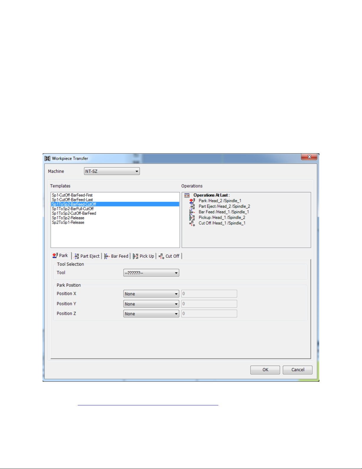
10.4. SP1 To SP2- BarFeed-Cutoff
This is a transfer from the main spindle to the sub spindle.
The following operations will be created:
Park operation on the lower turret (not used on single turret machines)
Part Eject Cycle (on lower turret on NT-SZ, on upper turret on all other machines)
Bar feed by stopper on upper head
Pickup Operation by sub spindle
Cutoff Operation. On the upper head.
Refer to the Operation Tabs in the Workpiece Transfer Utility section for a detailed expiation of
the settings in operation tabs.
68
Page 76
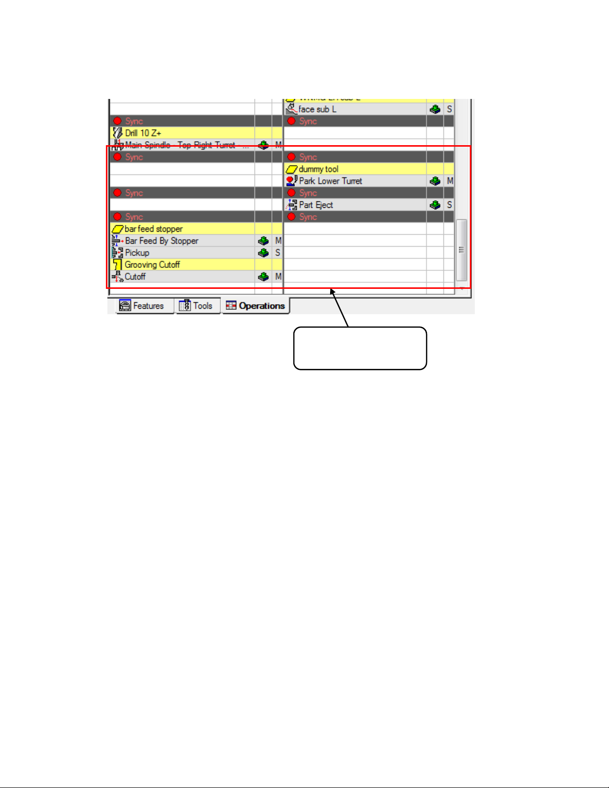
Added Syncs and
Operations
Below is an example of a file after the transfer was applied to an NT-SZ file:
Notes:
This same option exists on all of the NT machines, non-lower turret machines will not have the
sync or park operation added and the part eject cycle will be on the upper turret, otherwise they
are the same.
NT000-SZ and NT000-WZ machines will also have the part eject cycle on the upper head
69
Page 77
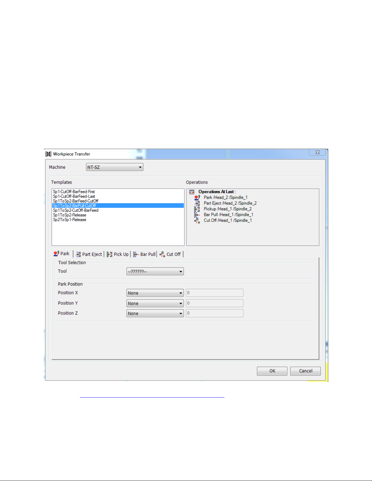
10.5. SP1 To SP2- BarPull-Cutoff
This is a transfer from the main spindle to the sub spindle.
The following operations will be created:
Park operation on the lower turret (not used on single turret machines)
Part Eject Cycle (on lower turret on NT-SZ, on upper turret on all other machines)
Pickup Operation by sub spindle
Bar Pull with sub spindle
Cutoff Operation. On the upper head.
Refer to the Operation Tabs in the Workpiece Transfer Utility section for a detailed expiation of
the settings in operation tabs.
70
Page 78
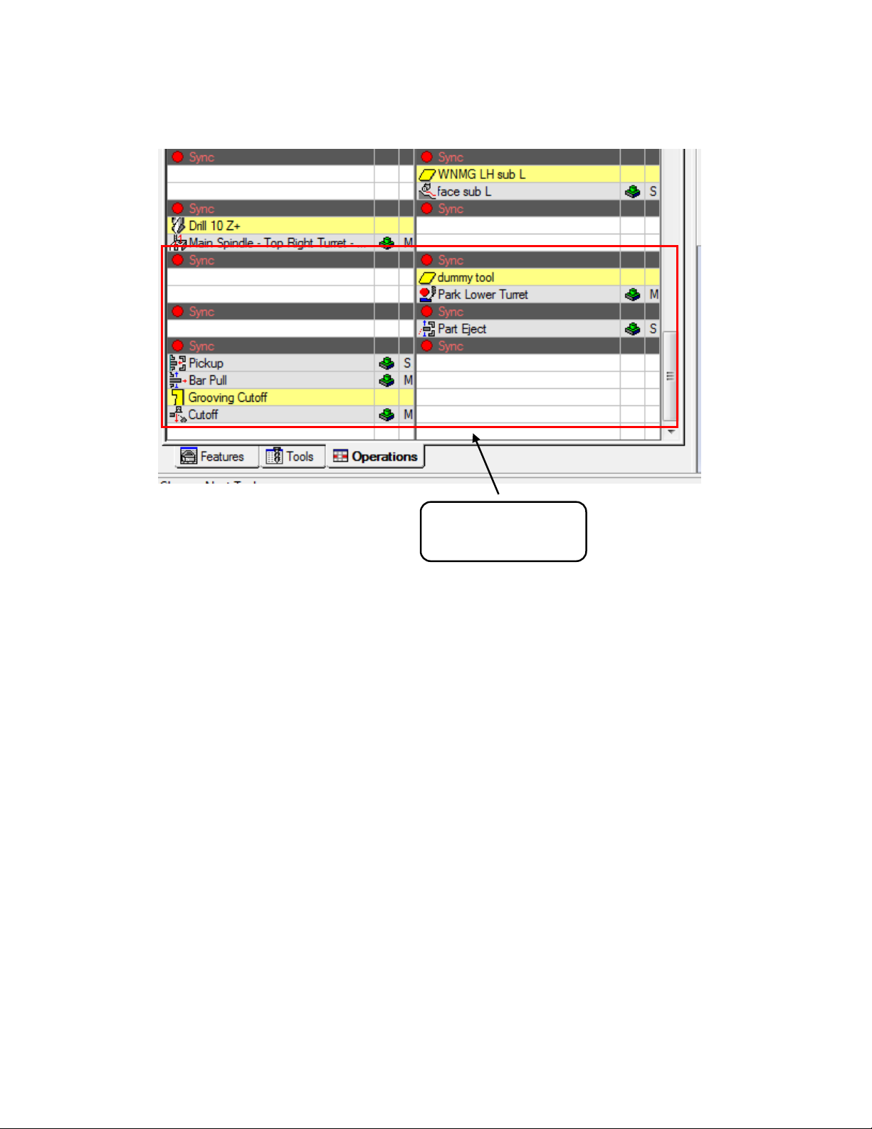
Added Syncs and
Operations
Below is an example of a file after the transfer was applied to an NT-SZ file:
Notes:
This same option exists on all of the NT machines, non-lower turret machines will not have the
syncs or park operation added and the part eject cycle will be on the upper turret, otherwise they
are the same.
NT000-SZ and NT000-WZ machines will also have the part eject cycle on the upper head
71
Page 79
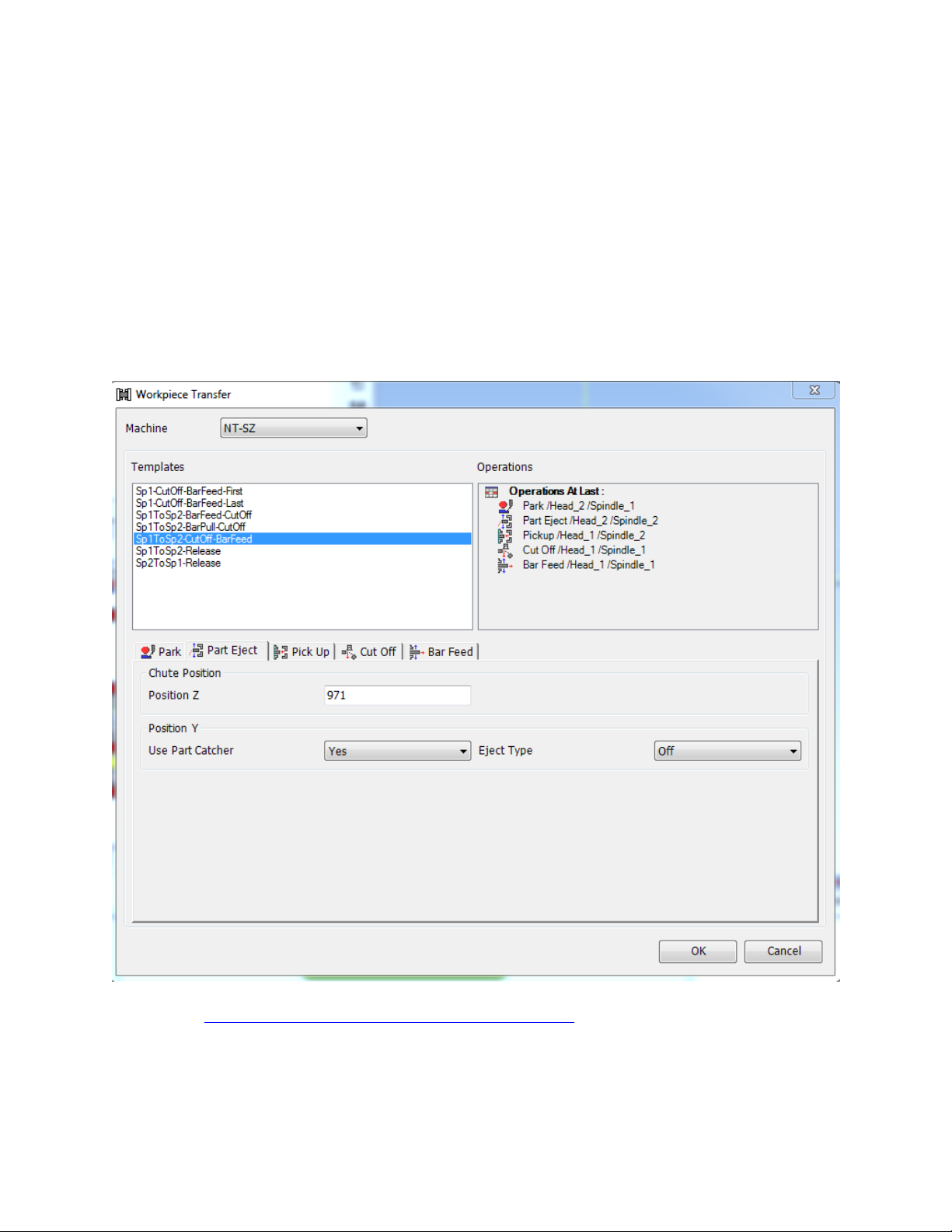
10.6. SP1 To SP2-Cutoff-BarFeed
This is a transfer from the main spindle to the sub spindle.
The following operations will be created:
Park operation on the lower turret (not used on single turret machines)
Part Eject Cycle (on lower turret on NT-SZ, on upper turret on all other machines)
Pickup Operation by sub spindle
Cutoff Operation. On the upper head.
Bar feed by stopper on upper head
Refer to the Operation Tabs in the Workpiece Transfer Utility section for a detailed expiation of
the settings in operation tabs.
72
Page 80
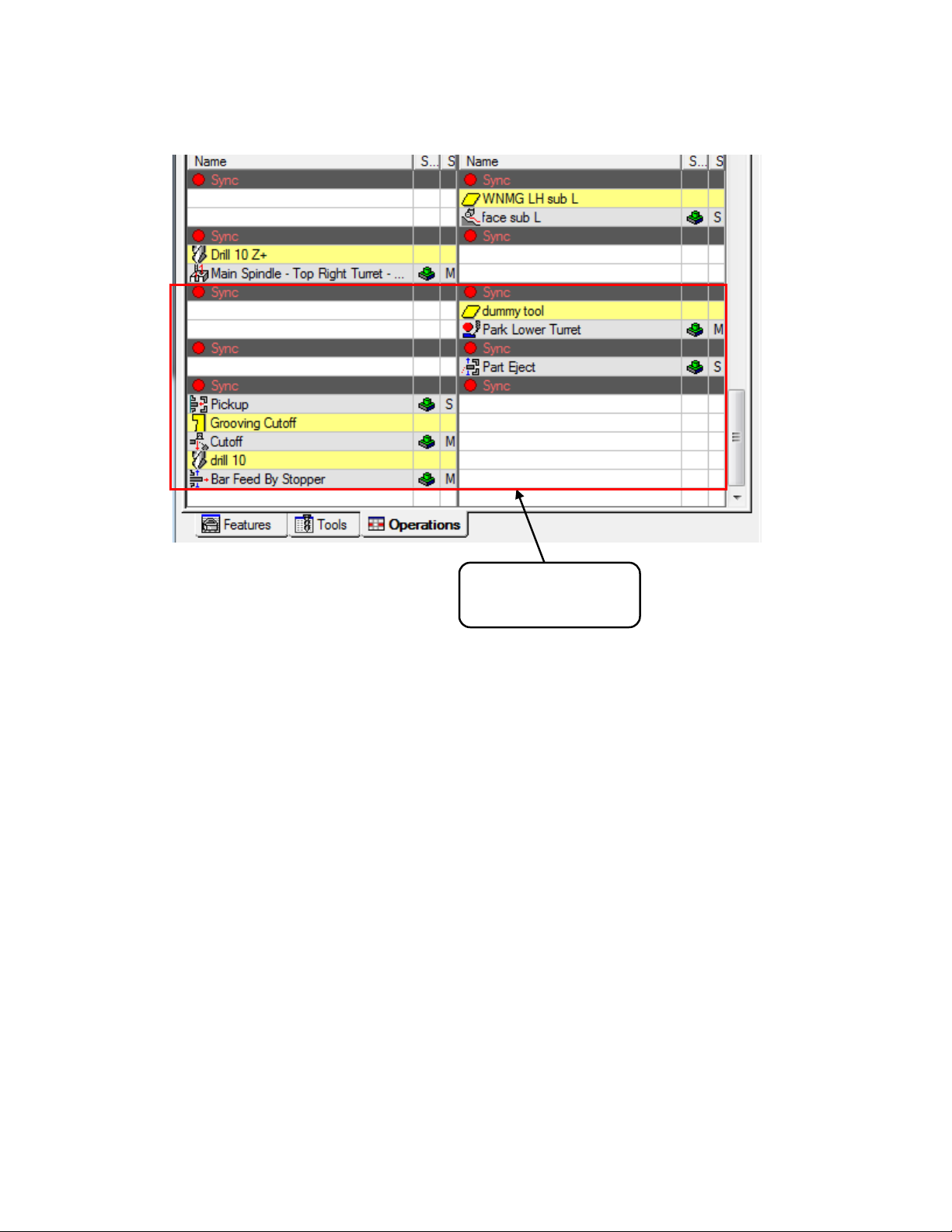
Added Syncs and
Operations
Below is an example of a file after the transfer was applied to an NT-SZ file:
Notes:
This same option exists on all of the NT machines, non-lower turret machines will not have the
syncs or park operation added and the part eject cycle will be on the upper turret, otherwise they
are the same.
NT000-SZ and NT000-WZ machines will also have the part eject cycle on the upper head
73
Page 81

10.7. SP1 To SP2-Release
This is a transfer from the sub spindle to the main spindle.
The following operations will be created:
Park operation on the lower turret (not used on single turret machines)
Part Eject Cycle (on lower turret on NT-SZ, on upper turret on all other machines)
Pickup Operation by main spindle
Release Operation by the sub spindle.
Refer to the Operation Tabs in the Workpiece Transfer Utility section for a detailed expiation of
the settings in operation tabs.
74
Page 82
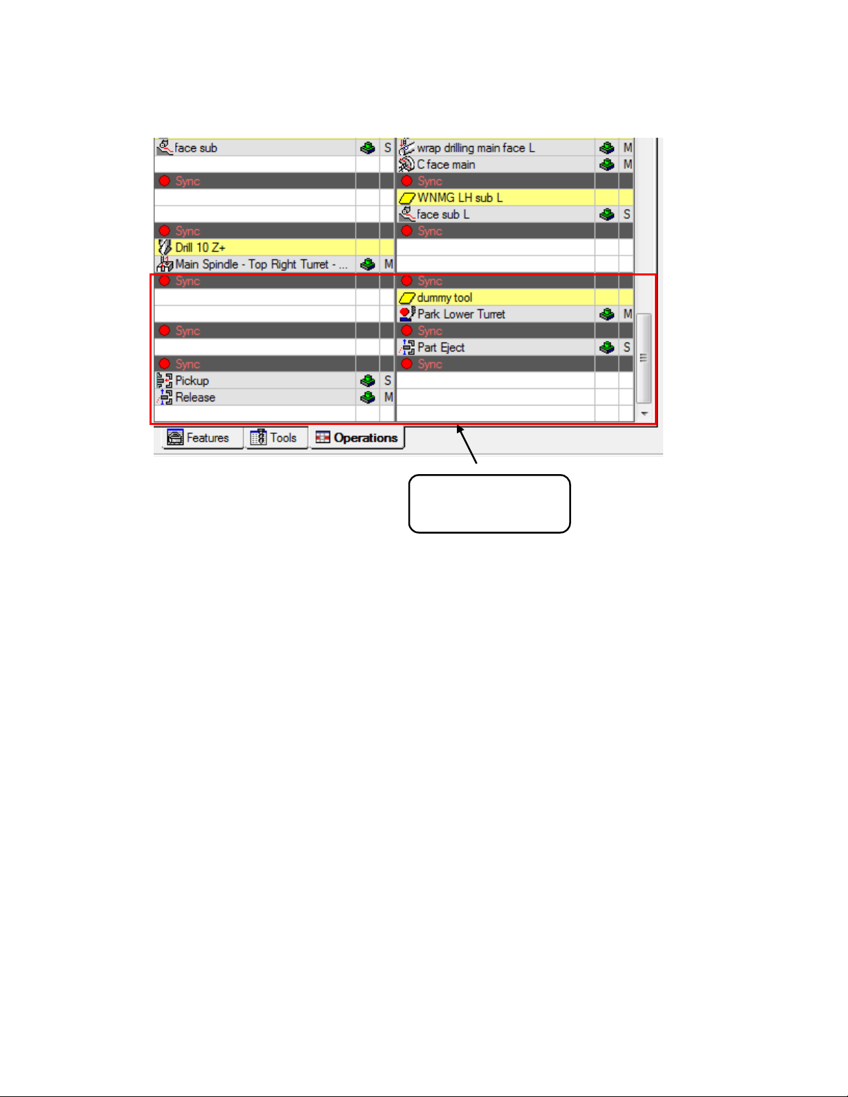
Added Syncs and
Operations
Below is an example of a file after the transfer was applied to an NT-SZ file:
Notes:
This same option exists on all of the NT machines, non-lower turret machines will not have the
syncs or park operation added and the part eject cycle will be on the upper turret, otherwise they
are the same.
NT000-SZ and NT000-WZ machines will also have the part eject cycle on the upper head
75
Page 83
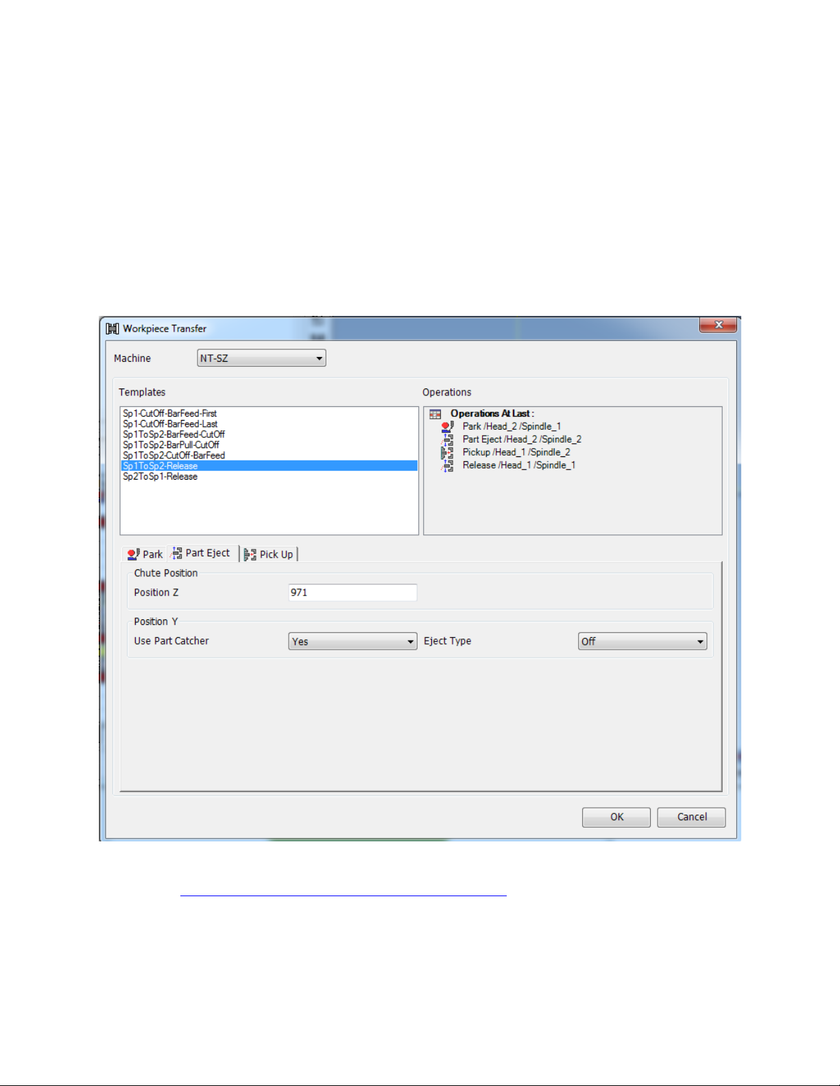
10.8. SP2 To SP1-Release
This is a transfer from the main spindle to the sub spindle. The following operations will be
created:
Park operation on the lower turret (not used on single turret machines)
Part Eject Cycle (on lower turret on NT-SZ, on upper turret on all other machines)
Pickup Operation by sub spindle
Release Operation by the main spindle.
Refer to the Operation Tabs in the Workpiece Transfer Utility section for a detailed expiation of
the settings in operation tabs.
76
Page 84
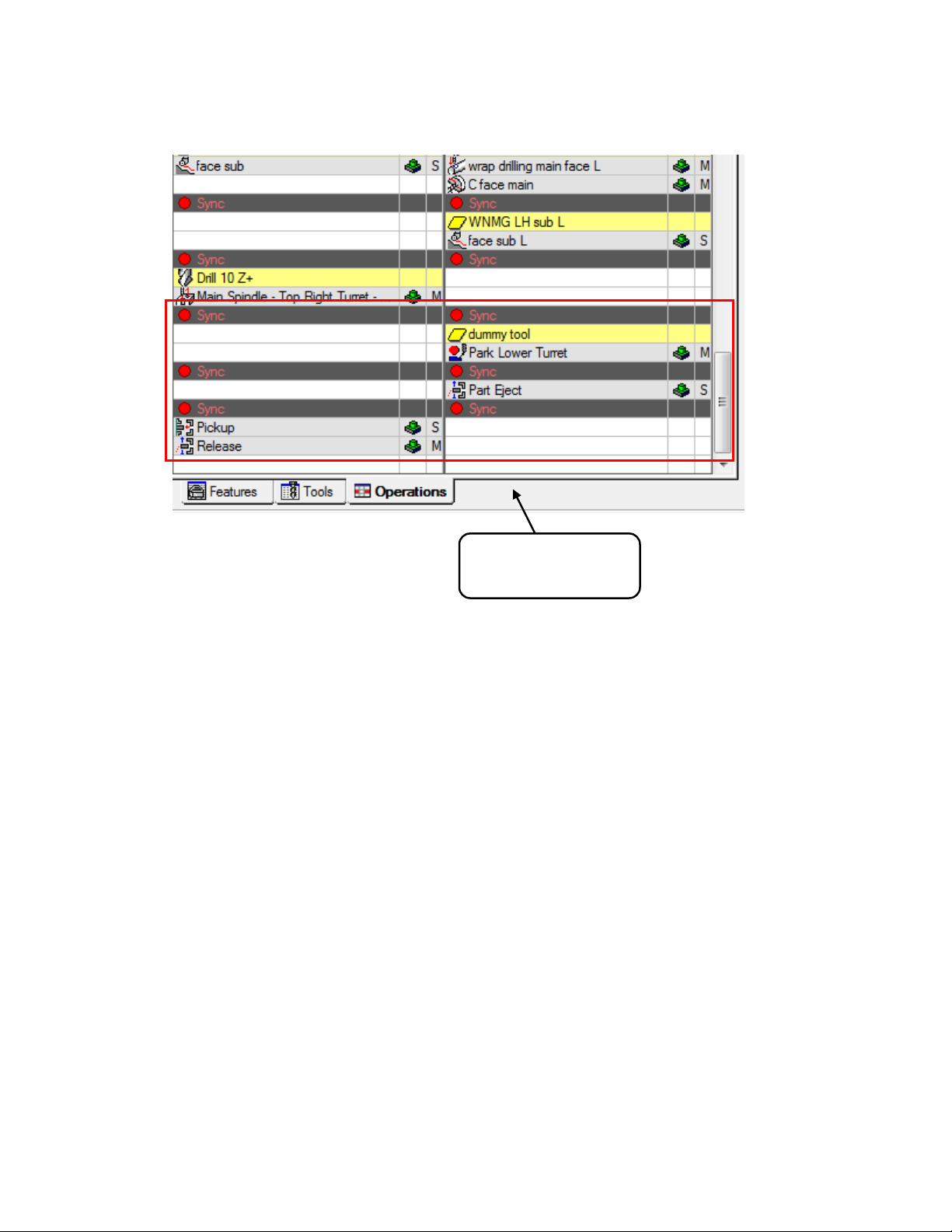
Added Syncs and
Operations
Below is an example of a file after the transfer was applied to an NT-SZ file:
Notes:
This same option exists on all of the NT machines, non-lower turret machines will not have the
syncs or park operation added and the part eject cycle will be on the upper turret, otherwise they
are the same.
NT000-SZ and NT000-WZ machines will also have the part eject cycle on the upper head
77
Page 85
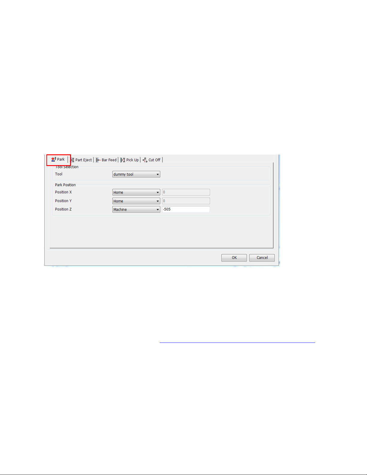
10.9. Operation Tabs in the Workpiece Transfer Utility
In this section the specific settings used by the different tabs (Operations) created by the part
transfer utility and how to modify them once the operation(s) are created.
10.9.1. Park
The park tab is used for lower turret machines. It is used to park the lower turret under the
main spindle during prior to a transfer. The settings on this page will be used in the creation
of a park operation.
The Park Tab has the following settings:
Tool: The addin does not allow us to not select a tool as the new park operation does,
but you can just select the same tool that is used by the previous operation.
Park Position X: Recommend setting is “Home”
Park Position Y: Recommend setting is “Home”
Park Position Z: Recommend setting is “Machine” and the Far left position of your
machines travel (see chart in Park head/ turret to its minimum travel position (G53)
section for this location on your machine model)
78
Page 86
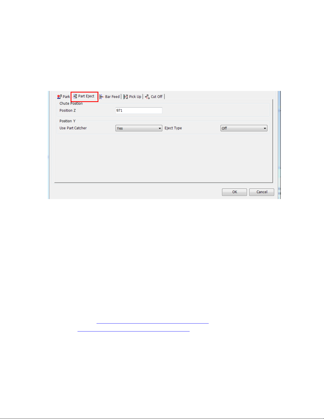
10.9.2. Part Eject
The part Eject Tab is used to fill in specific settings used in the Part Release operation to
release the part from the sub spindle. The settings on this page will be used in the creation of
a release operation.
The Eject Tab has the following settings:
Chute Position Z: This is only used for simulation; this does not affect the NC code.
This is the location on the screen relative to Esprit World Zero that the part will be
released at.
Use Part Catcher (Yes/No): This set the part chute filed in the part release operation.
o If set to NO the post will output M0’s in the NC code to stop the machine to
allow the operator to manually remove the part from the machine. (Lower
Turret machines will have the M00 in both turrets NC code)
o If set to yes the part will be removed automatically via the part chute.
Eject Type (Off/M47) If selected an M47 will be output in the NC code in the part
release.
o Then M47 is not supported on the NT1000 machines this needs to be set to
OFF for an NT1000 machine.
o Then NT-S also uses an M360\M361. The addin does not currently support
the M360\M361 but you can set this manually after the operation is created.
See Workpiece Ejector (NT-S and NT-SZ Only) section below.
See Smart Loader Shutter (M37) (NT1000 only) section below for information on
activating the Smart Loader Shutter on and NT1000 machine. This can be set after the
release operation is created since this feature is not supported by the workpiece
transfer utility at this time.
Note: At the end of the release cycle on an NT1000 machine A axis will be at G330 P4
and the BW axis will be at BW0
79
Page 87
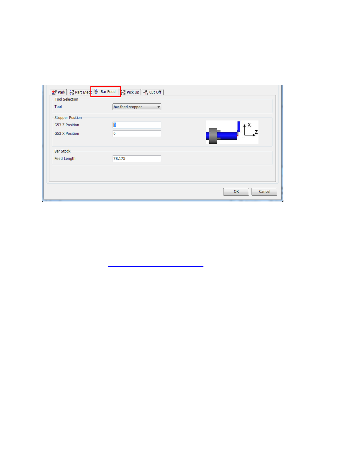
10.9.3. Bar Feed
The bar feed tab is used to setup a bar feed by stopper type of operation. The settings on this
page will be used in the creation of a bar feed operation.
The Bar Feed Tab has the following settings:
Tool: This is the tool used for the bar stopper
Stopper Position G53 Z position: Position in the NC code for the bar stopper location
Stopper Position G53 X position: Position in the NC code for the bar stopper location
o Note if the Stopper position is left zero the NC code will move the bar stopper to
the Z position equal to the value in the bar feed distance.
o Refer to Bar Feed positions relative to G53 section below for additional
information on these values and how to change them after the operation is created.
Bar Stock Feed length: feed length of the stock. This value is critical as it is used to shift
the Z axis for the cutoff location.
o This value must be the exact as every operation following the bar feed operation
will be shifted in Z by this distance.
o Set the Feed Length (2) equal to Length of the part + Cut-off tool width + Length
of stock for facing the front side and the backside of the part.
Notes:
The bar feed operation is only setup for the upper head and takes place at B-90 Degrees.
The simulation of the B axis head will not match the NC code unless you modify the XZ
positions in the bar feed operation.
80
Page 88
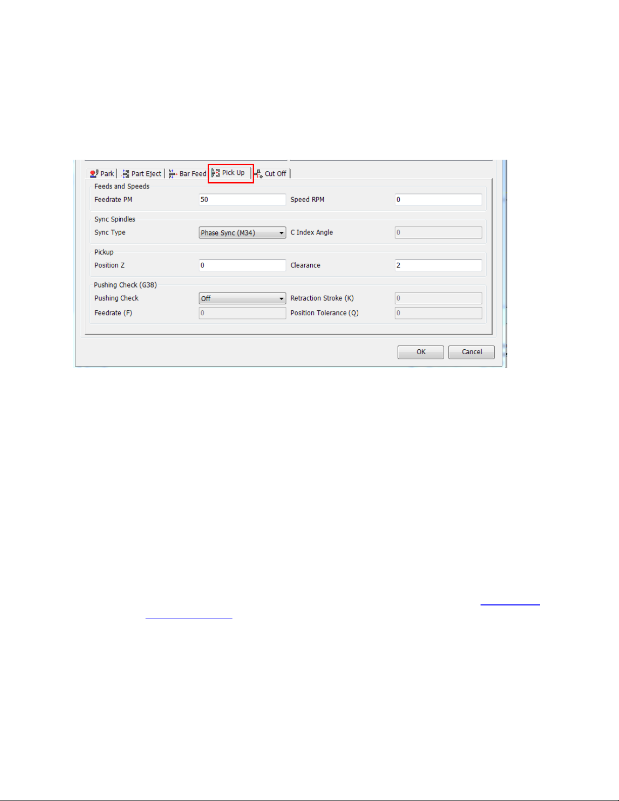
10.9.4. Pick Up
The Pickup Tab is used to set the values needed for the pick up portion of the transfer. The
settings on this page will be used in the creation of a pickup operation.
The Pick Up Tab has the following settings:
Feeds and Speeds
o Feedrate: Feedrate used in the pickup operation
o Speed RPM: Spindle RPM used in the pickup operation (used in M34 or M35
modes only)
Sync Type:
o Phase Sync (M34): Option used for cutoff type transfers
This option will set the Sync Spindle field in the pickup operation to
“Oriented”
o Speed Synced (M35): Option used for cutoff type transfers
This option will set the Sync Spindle field in the pickup operation to
“Speed and Direction Only”
o Spindle Orient (M19): Option used for non-cutoff type transfers
o C-Axis Connect (M45): Option used for non-cutoff type transfers
o C Index Angle: Used when C-Axis Connect Sync type is used. This is the C axis
angle of the spindles during the transfer. Typically set to 0. Refer to C axis angle
for pick operation section below for additional information on these values and
how to change this value after the operation is created
Pickup
o Position Z: Z position relative to World zero in ESPRIT for pickup point (note
this will always be A0 in the NC code)
o Clearance: Distance added to the pickup point to transition from rapid to feed (in
addition to the clearance distance the post adds the sub spindle jaw length to the
initial rapid position)
81
Page 89
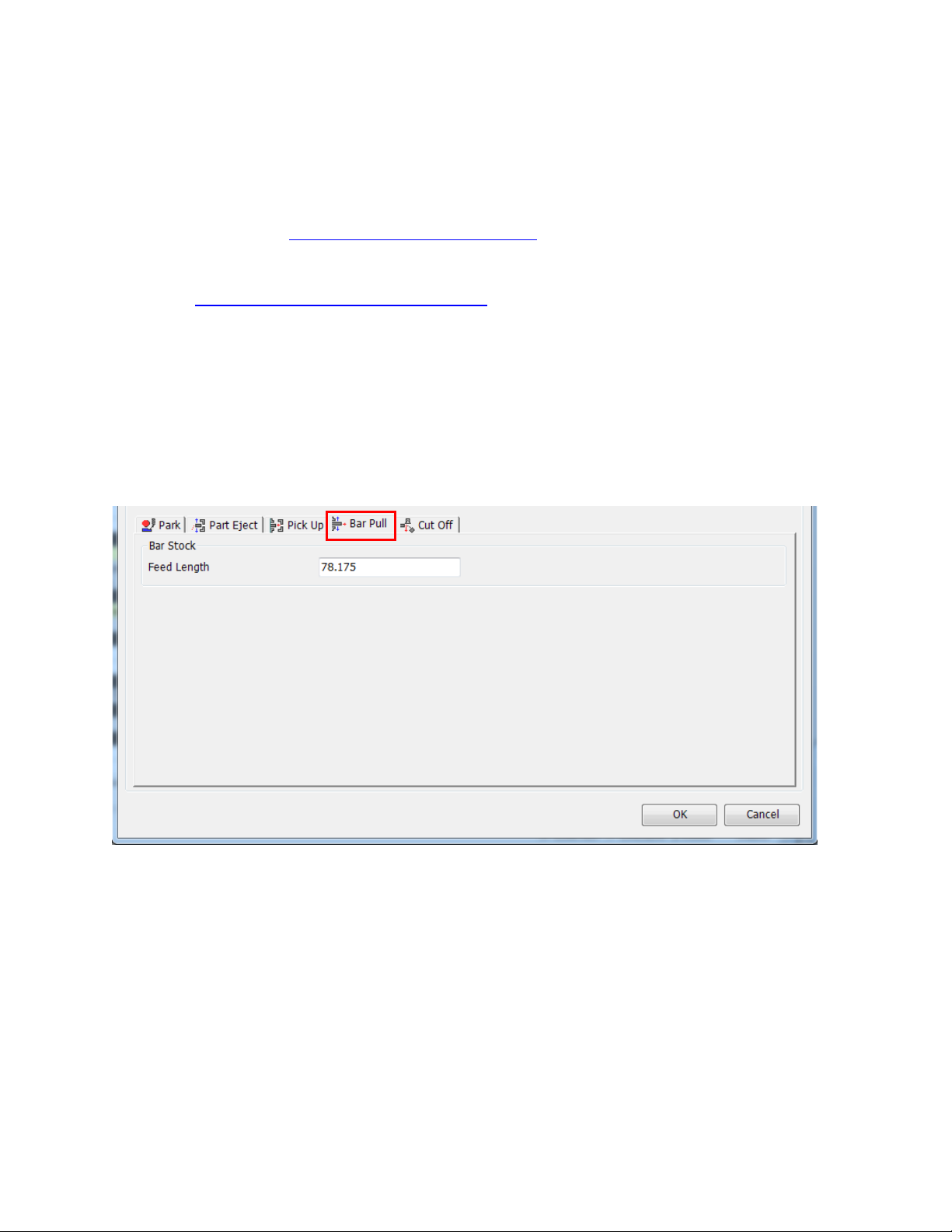
Pushing Check (G38)
o Pushing Check (On\Off): turns on or off the G38 Option
o Feedrate: Feedrate for G38 command
o Retraction Stroke (K): K value for G38 command
o Position Tolerance (Q) : Q value for G38 command
o Refer to Workpiece Pushing Check (G38) section below for additional
information on these values and how to change them after the operation is created
For information about setting up a different work coordinate for the pickup operation see
the Work Coordinate for Pickup Operation section below. This can be set after the pickup
operation is created since this feature is not supported by the workpiece transfer utility at
this time.
10.9.5. Bar Pull
When programming a transfer type with a barpull with the sub spindle, the barpull tab only has
one setting. The settings on this page will be used in the creation of a pickup operation.
Set the Feed Length (2) equal to Length of the part + Cut-off tool width + Length of stock for
facing the front side and the backside of the part.
82
Page 90
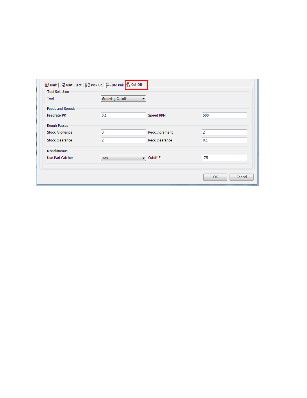
10.9.6. Cutoff
The Cutoff Tab is used to set the values needed for the cutoff portion of the transfer. The settings
on this page will be used in the creation of a cutoff operation.
The Cutoff Tab has the following settings:
Tool: Sets the tool used for the cutoff operation
Feeds and speeds section: Sets Feedrate and RPM for cutoff operation
Rough passes section
o Stock allowance: Sets Rough Stock allowance in the cutoff operation
o Stock Clearance: Sets the Stock Clearance in the cutoff operation
o Peck Increment: Sets Peck Increment in the cutoff operation
o Peck Clearance: Sets Peck Clearance in the cutoff operation
Miscellaneous
Use Part Cather: Sets Use Parts Cather in cutoff operation
Cutoff Z: Z location of the cutoff operation feature that is created by the addin to be used
for the cutoff operation. This is typically the finish length of the part (assuming that the
main spindle work coordinate is a world zero in ESPRIT). This value is always from
World Zero in ESPRIT. This is loaded with the value in the Part Stock Length in the
ESPRIT machine setup page.
83
Page 91

10.10. Custom Settings for Part Transfer Cycles
While programming a part transfer cycle for the Mori Seiki NT Series machines, there are
several options that the user has to tailor the cycle to their needs. Below is a short description of
how to program these special functions in ESPRIT.
Some of these features are supported by the Workpiece Transfer utility and can be setup when
the operations are created, others are not supported by the utility at this time but can be setup
after the operation is created.
Once the operation is created these settings can be modified in the given operation(s) by
navigating to the custom tab in the operation and editing the settings to the desired values.
84
Page 92
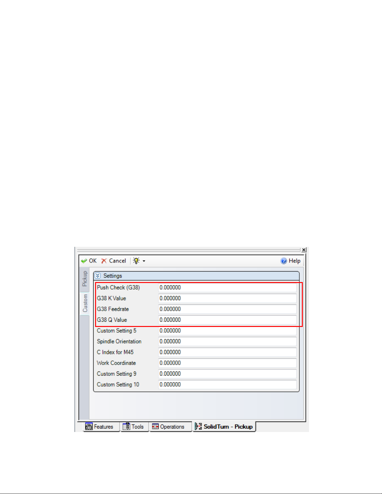
10.10.1. Workpiece Pushing Check (G38)
In the workpiece transfer operation, when the position error of the A-axis servomotor of
headstock 2 reaches the parameter set value, the workpiece is judged to have been brought into
contact with the reference face of chuck 2 or chuck 1. Then, chuck 2 or chuck 1 clamps. In
ESPRIT, it is possible to set the feedrate (F_), tolerance (Q_), and A-axis retraction stroke (K_)
for a G38 workpiece pushing check cycle. The format of the operation is as follows:
G38 A_ K_ F_ Q_
The Push Check settings are entered into the Pickup Operation in Esprit. The Mori Seiki Transfer
will enter these values into the page, but if you need to modify them the values are in the
following locations:
Push Check (G38) (Custom Setting 1) needs to be set to a value of 38 If this is zero the
settings below will have no effect on the NC code.
G38 K value (Custom Settings 2) is the a-axis retraction stroke value K_.
G38 Feedrate (Custom Setting 3) is the federate F_.
G38 Q value (Custom Setting 4) is the tolerance Q_.
Enter the appropriate values for these variables in their respective custom setting box to output
them in the code.
85
Page 93
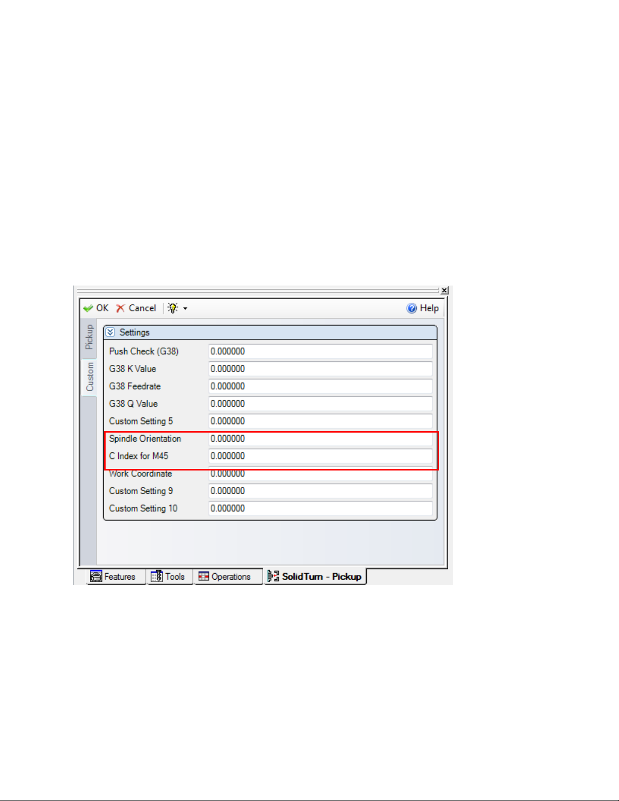
10.10.2. C axis angle for pick operation
During a non-cutoff type of transfer, the turning spindles are stopped.
Using the Spindle Orientation field (Custom Setting 6) on the Custom tab of the Pickup
operation, the user can specify how to orient the spindles. Set Spindle Orientation field to 19 to
use spindle orientation (M19 / M219) or set Spindle Orientation field to 45 to use the milling Caxis mode (M45 / M245).
When using milling C-axis mode, set the C axis Index for M45 field (Custom Setting 7) to
specify the C angle value to position the C axis to during the transfer. Make sure to enter a
correct value for C. For example, if C-axis roll-over is on, C has to be contained between -360
and 360.
NOTE: The milling C-axis mode is the default. So if the user omits a value in the Spindle
Orientation field (leaves it set to zero) or enters a wrong value, the spindles will be indexed using
this mode.
86
Page 94
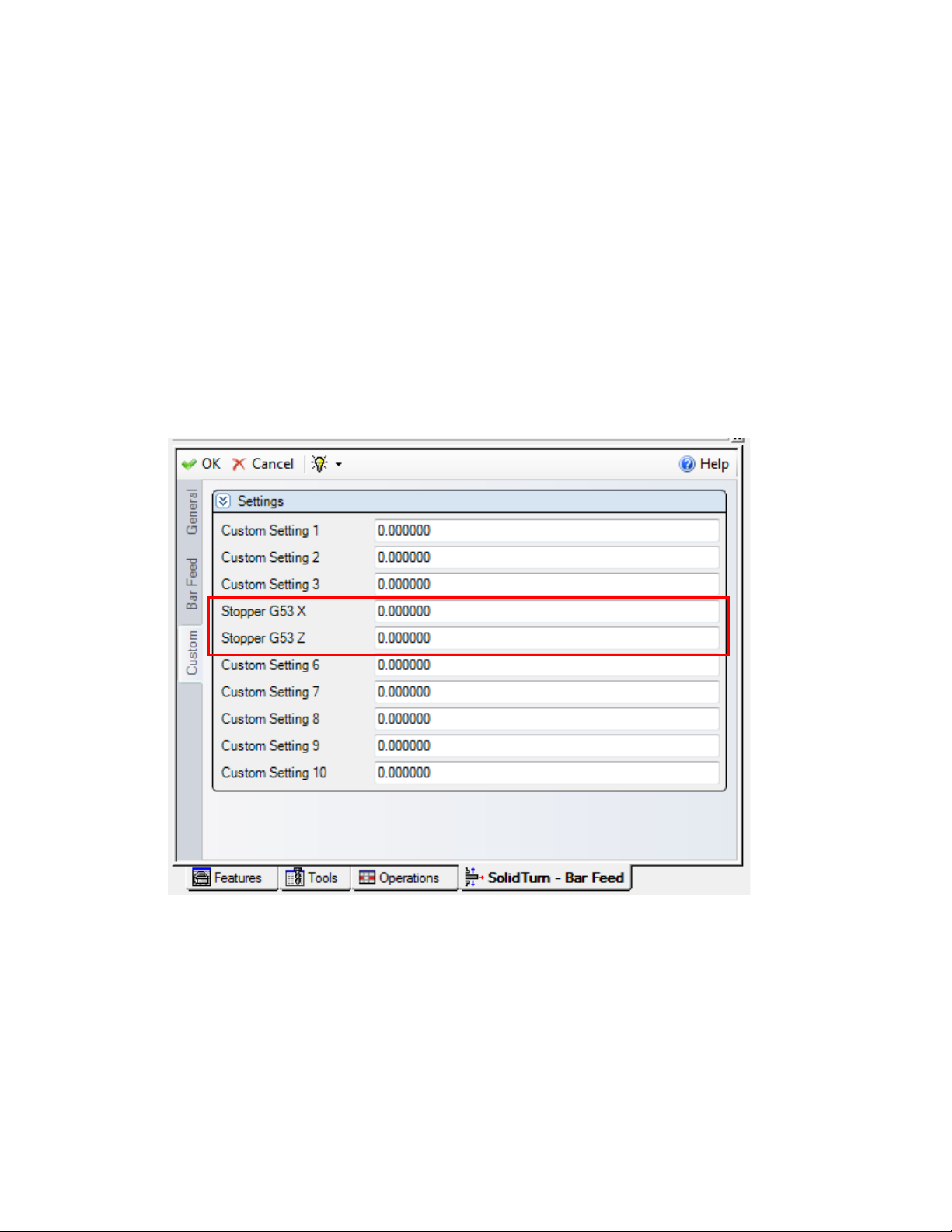
10.10.3. Bar Feed positions relative to G53
The Bar feed operation uses two custom settings to output the stopper position relative to
machine zero (G53)
On the Custom tab, enter in the Stopper G53 X field (Custom Setting 4) the X position (in G53
work coordinate) of the stopper tool and in Stopper G53 X field (Custom Setting 5) the Z
position (in G53 work coordinate) of the stopper tool.
If these values are left zero the post will position the bar stopper to the Z location in the
operation relative to the active work coordinate for the spindle selected in the bar feed operation
(typically this is the main spindle).
87
Page 95
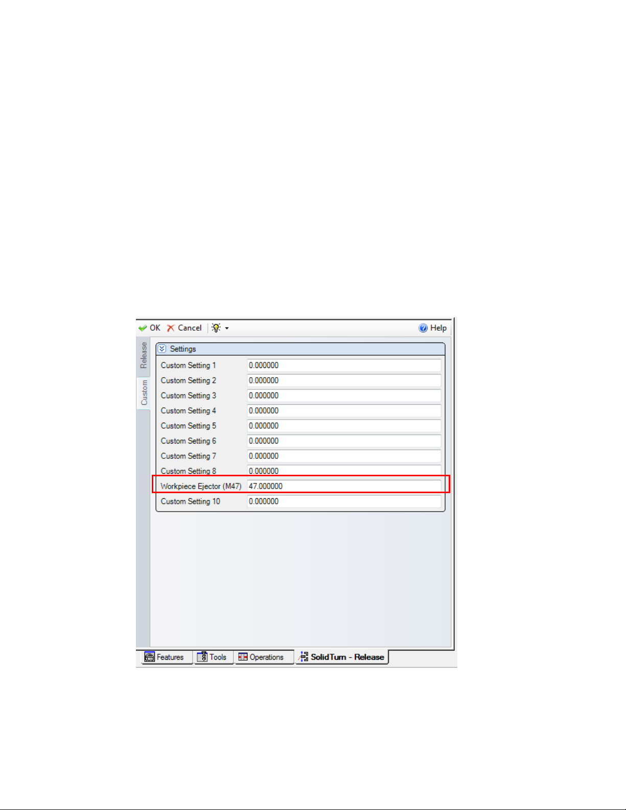
10.10.4. Workpiece Ejector (NT-S and NT-SZ Only)
In the case that the workpiece is small or delicate, it is possible to use the Workpiece Ejector to
ensure that the workpiece has been removed from the chuck. To initiate this function, navigate
to the Custom tab of the Release operation used to eject the part from the sub spindle.
10.10.4.1. NT-S
The NT-SZ has the option of Set the Workpiece Ejector (Custom Setting 9) filed equal to 360 to
output M360/M361 or 47 to output M47 in the part release section of the NC code.
10.10.4.2. NT-SZ
Set the Workpiece Ejector (Custom Setting 9) filed equal to 47 to output M47 in the part release
section of the NC code.
88
Page 96
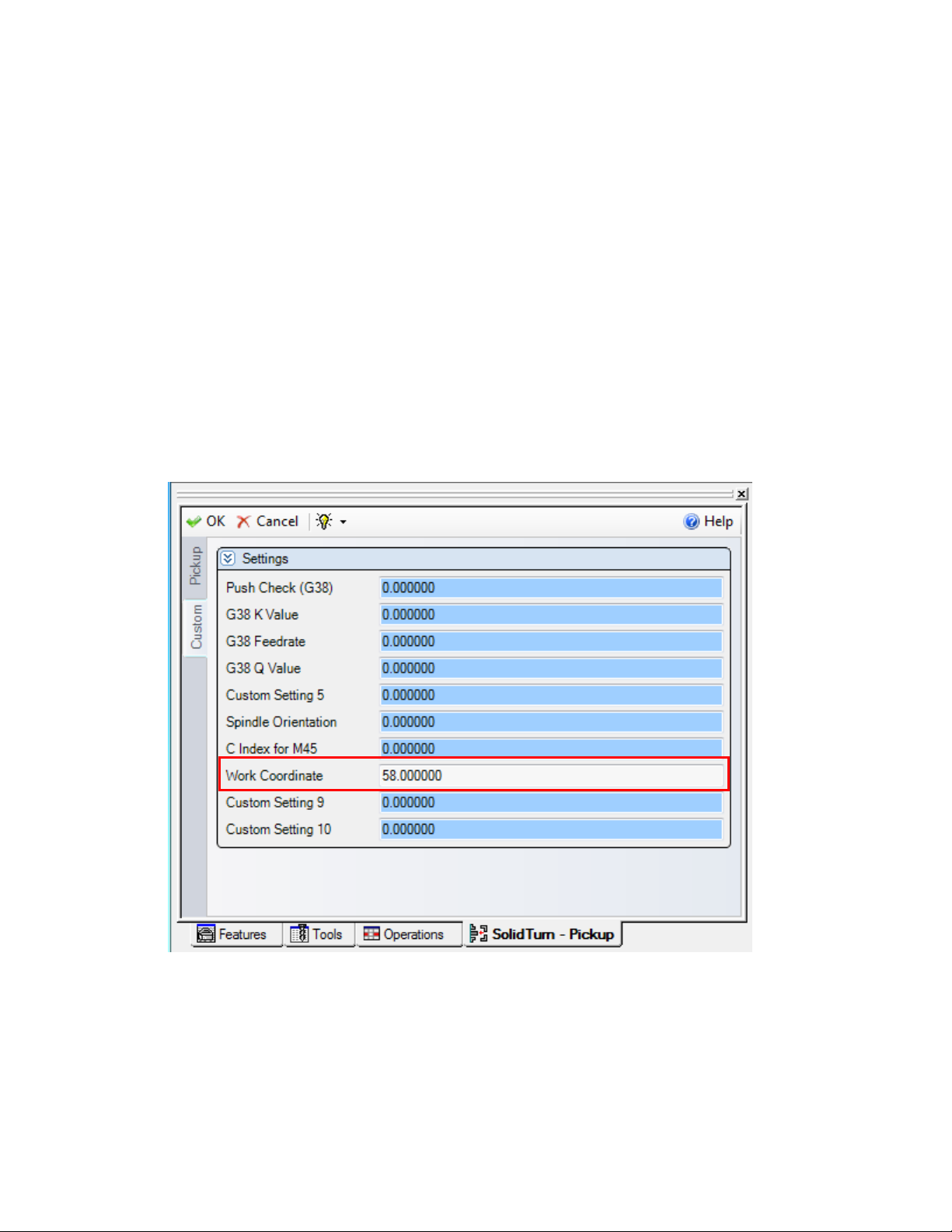
10.10.5. Work Coordinate for Pickup Operation
The turning work coordinate forces the part pickup operation into the Main Spindle Work
coordinate. If the users would like to use a different work coordinate for a pickup operation the
Turning Work Coordinate would not be able to be left in the auto run mode. This is a dangerous
situation.
To avoid this we have setup the Work Coordinate (Custom Setting 8) field in the pickup
operation for the work coordinate for the pickup operation. If this value is left zero or not 54, 55,
56, 57, 58, or 59, the post will output the work coordinate the pickup operation is tied to in the
NC code.
The most common use of using alternative work coordinate for the pickup operation is when the
using multiple pickup operations within the same file for doing long part machine and\or stock
repositioning.
89
Page 97
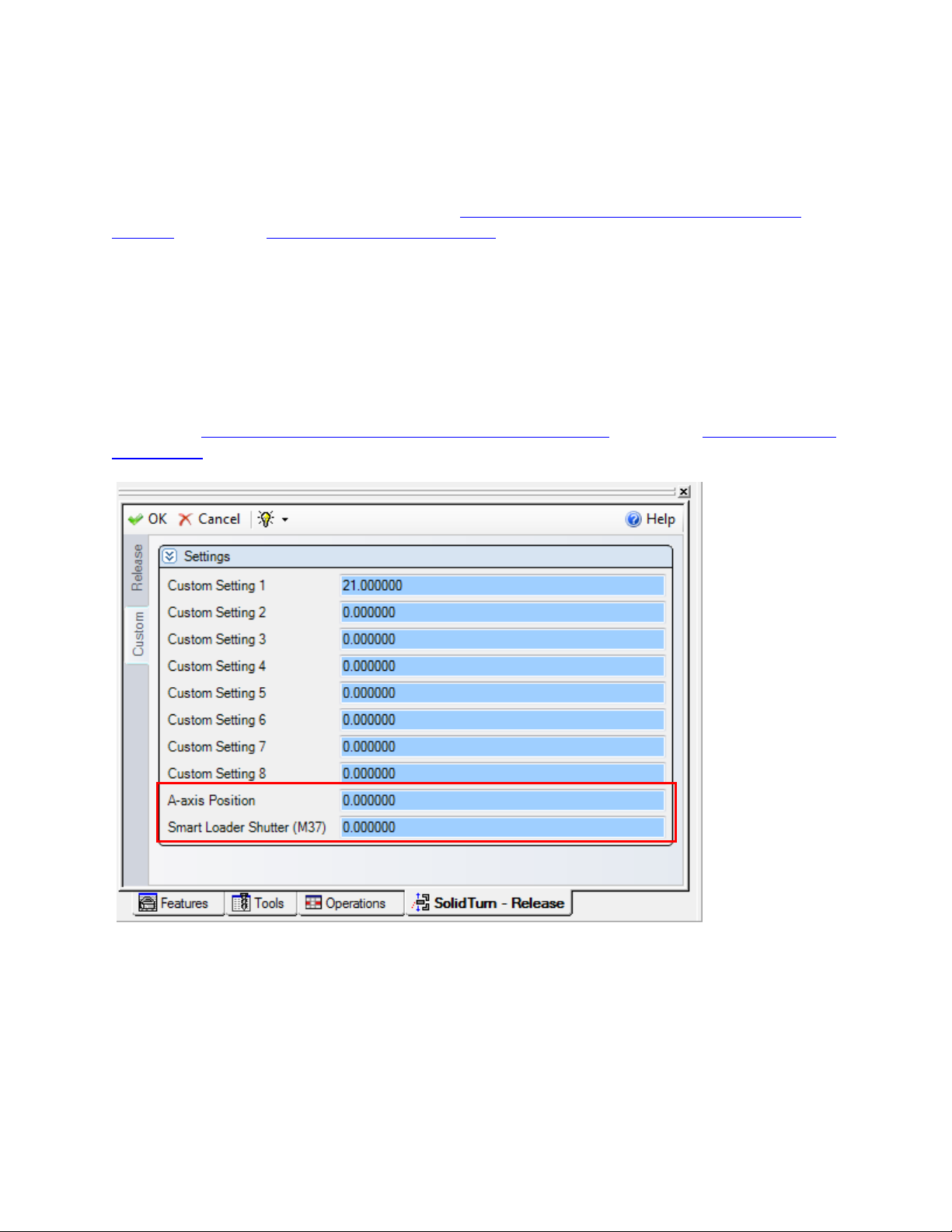
A axis position for part release (NT1000 only)
The NT1000 needs to know where the sub spindle will be when the part is released from the sub
spindle. This is set in Custom setting 9 in the part release cycle. This value needs to be relative
to the machine coordinate system. See section Special considerations when Programming an
NT1000 sub section Part Release from Sub Spindle section for additional information.
10.10.6. Smart Loader Shutter (M37) (NT1000 only)
If the Part Chute option is used on the NT1000 Part eject you have the option to use or not use
the Smart Loader Shutter. This is activated by putting a value of 37 in the Smart Loader Shutter
(Custom Setting 10) in the part release operation.
See section Special considerations when Programming an NT1000 sub section Part Release from
Sub Spindle section for additional information.
90
Page 98
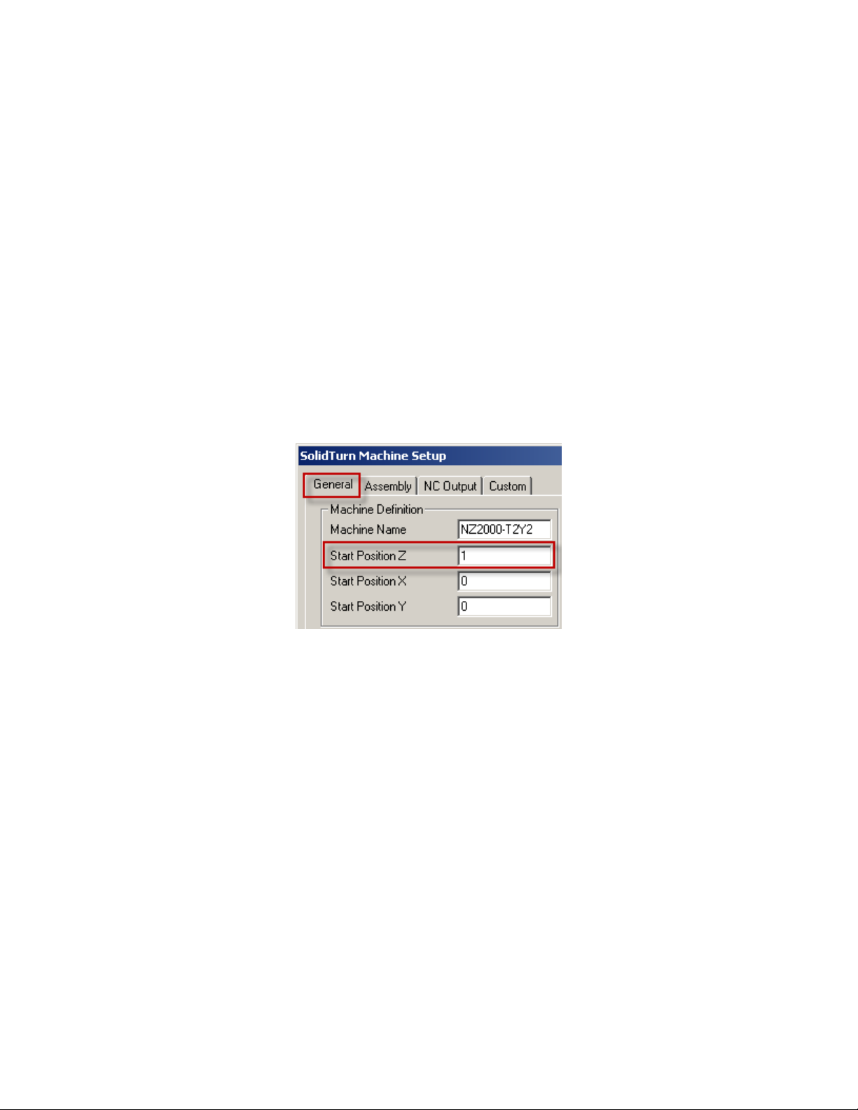
11. Working with Long Parts: Pickup\Barpull then
Simultaneous Machining
To support the stock with both spindles, you first need to pick it up (and, if needed, pull it) with
the spindle 2. You can after program your operations and in the code will be output the necessary
spindles synchronization and un-synchronization codes. Finally, once machining is completed,
you can program one of the transfer scenarios described in the previous parts at the end of the
operation list.
In order for the post to create the proper output to hold onto the part with both spindles transfer
there must be at least one operation in the lower turret’s operation list, even if it is just a park
operation.
Note: On the General tab of the Machine Setup, set the Start Position Z:
Start Position Z = Length of stock for facing the front side of the part or position of the stock in
spindle 1 before pick up for synchronized machining
The typical steps to follow are:
1. Machining the parts on the spindle 1 and spindle 2 sides
2. Catching the finished part in the spindle 2
3. Picking the part in the spindle 1 with the spindle 2
4. Pulling the bar with the spindle 2 (if needed)
5. Machining the part on the spindle 1 side while the spindles are synchronized and
are both supporting the part
6. Perform one of the previously described transfer scenarios to transfer the part to
spindle 2 side
7. Looping for next parts
Notes:
It is possible to program multiple Pickup\Bar Pull operations in a row with no machining
between them) to pull the part out of the spindle further then you have travel in the A axis.
91
Page 99
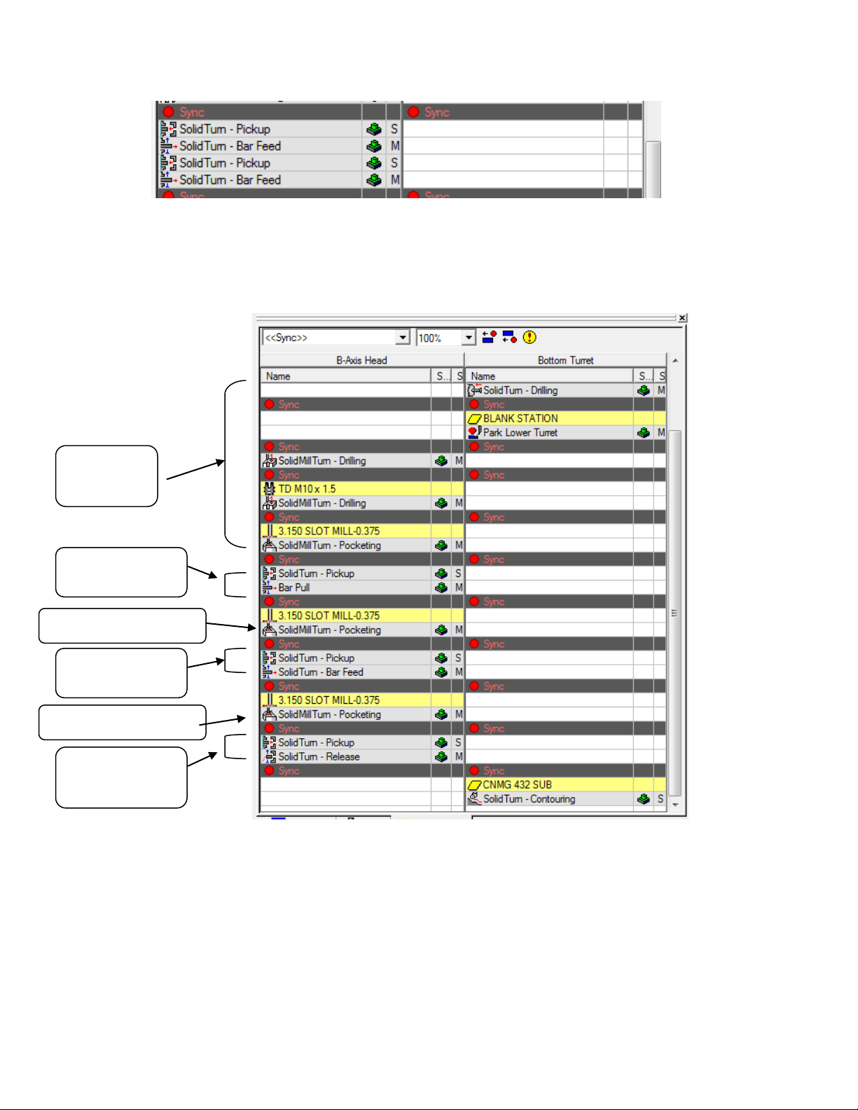
Initial
Machining
Initial Pickup/
Bar Pull
Machining continues
Second Pickup/
Bar Pull
Machining continues
Transfer to Sub
Spindle
It is possible to program several Pickup\Bar Pulls with machining between them to machine the
part at different locations as you pull the part through the machines
If multiple pickup\bar pulls are programed the C axis orientation options will only be read from
the first pickup operation.
Long part machining can be canceled by either performing a release operation or a part transfer.
12. Stock Repositioning
The post supports the ability to pull stock out of either the main or sub spindles with the opposite
spindle with Pick\Barpull\Release operations. This is used to machine some operations with the
92
Page 100

part close to the spindle, then pull the part out longer to machine operations with the sub spindle
while supporting the part with a Steady Rest, Tailstock or unsupported.
Performing these operations is the same as doing a Pickup\Bar pull as described above in the
Working with Long Parts: Barpull and Simultaneous Machining above, but with a release
operation added after the Pickup\Bar pull
93
 Loading...