

Page 1
1
NMV
This manual was prepared with the assumption that the intended reader does have
working knowledge of Esprit and NMV programming experience so that he fully
understands the information it contains.
Page 2

2
Table of Contents
1. Introduction ................................................................................................................. 4
2. Defining Work Coordinates ........................................................................................ 4
2.1. Standard Work Coordinate System G54 to G59 ................................................. 4
2.2. Extended Work Coordinate System G54.1 P1-300 ............................................ 5
2.3. Dynamic Fixture Offset Work Coordinate System G54.2 P............................... 6
2.4 Tilted Plane Work Coordinate System G68.2..................................................... 7
2.5 Macro Work Coordinate System G65 P9681 ..................................................... 8
3. Simultaneous 5 Axis Machining Settings ................................................................... 9
4. Turning Settings ........................................................................................................ 13
5. Drill Cycles ................................................................................................................... 18
5.1 Drill ................................................................................................................... 19
5.2 Additional Drilling Notes ................................................................................. 20
6. 4th Axis Wrap Milling Cycles ....................................................................................... 20
6.1 Cylindrical Interpolation ................................................................................... 20
6.2 Polar Interpolation ............................................................................................ 21
7. 3 Axis Freeform and SolidMill Cycles ......................................................................... 22
7.1 NURB Output ................................................................................................... 22
8. Coolant Codes ............................................................................................................... 23
8.1 Primary Coolant Code....................................................................................... 23
8.2 Secondary Coolant Code................................................................................... 24
8.3 Coolant Pressure Code ...................................................................................... 25
9. Custom Codes ............................................................................................................... 26
9.1 M Codes at the Beginning and End of an Operation ........................................ 26
9.2 AI Contour Control ........................................................................................... 27
9.3 Cutting Mode (G332) ........................................................................................ 27
9.4 Rapid Feedrate (G01 F)…………………..…………………..……………… 28
10. Post Output Configuration .................................................................................... 29
10.1. F15 Format Switch ............................................................................................ 30
10.2. TCP TYPE ........................................................................................................ 30
10.3. Program End Code ............................................................................................ 30
10.4. B and C Go Home Motion ................................................................................ 30
10.5. C-Axis Roll Over .............................................................................................. 30
10.6. Custom String 10 .............................................................................................. 31
10.7. ESPRIT Version................................................................................................ 31
11. Machine Setup Custom Settings ........................................................................... 31
11.1 Fanuc Output Style ........................................................................................... 31
11.2 RTCP Output .................................................................................................... 31
11.3 End of Program M code Output ........................................................................ 31
11.4 Rollover for C Axis ........................................................................................... 32
11.5 Machine Name .................................................................................................. 32
11.6 Machine Model Number ................................................................................... 32
11.7 Tool Holder Type .............................................................................................. 32
11.8 TOOLTABLE ................................................................................................... 32
11.9 StopTCOnly ...................................................................................................... 33
11.10 NTCOnly......................................................................................................... 33
Page 3

3
12. Rotary Retract Movement Setup ................................................................................. 33
12.1 Clearance........................................................................................................... 33
12.2 Tool Change ...................................................................................................... 34
12.2.1 X Safe Positions ............................................................................................. 35
13. Custom Settings Reference List .................................................................................. 35
13.1 Machine Setup .................................................................................................. 35
13.2 Operation Page .................................................................................................. 36
13.3 Tool Page .......................................................................................................... 36
Page 4
4
1. Introduction
This manual documents the Esprit NMV post processor version 3/12/12.
The E12_MSP_NMVDCG_2012-03-12.pst post supports the NMV machine tool with
and without the turning option
The post processor requires ESPRIT 2011 or higher.
2. Defining Work Coordinates
Program Datums on the machine can be defined as Work Coordinates in Esprit. Esprit
supports both Local and World Coordinate Systems. To set the Coordinate System in the
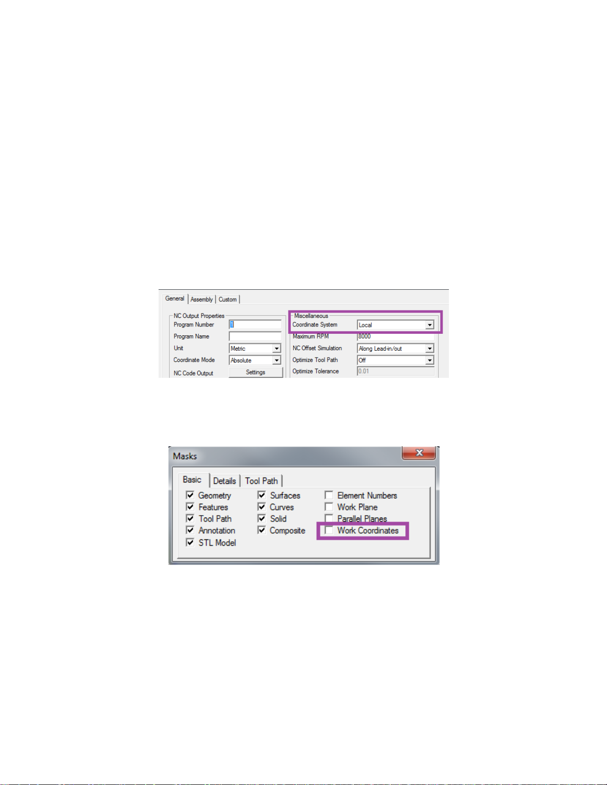
milling environment, go to Common Machining> Machine Setup> Coordinate Systems
and select between Local and World.
For most applications this will be set to Local.
To view your Work Coordinates in Esprit check the Work Coordinate box in in the
Masks box.
The following examples show Work Plane set to XYZ, for Mill. This setting will be
YZX when in MillTurn environment.
2.1. Standard Work Coordinate System G54 to G59
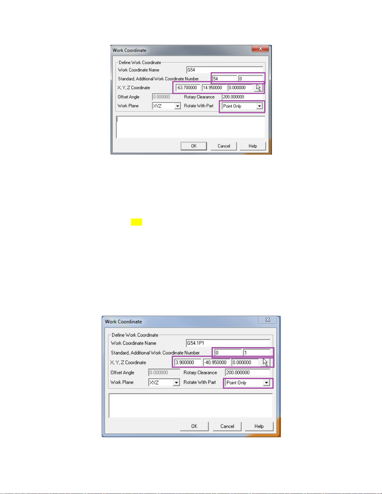
To define a Standard Work Coordinate set the Work Coordinate page as:
Page 5
5
Standard is the Work Coordinate Number and Additional Work Coordinate Number is set
to 0. XYZ is the location of the Work Coordinate in the file relative to the Work Plane.
Rotate with Part needs to be set to Point Only.
M06
G91 G28 Z0
G40 G80
G00 G90 G54
M11
M69
G00 B0.0 C0.0
M10
M68
G17 G94 X-6.538 Y28.5
G43 Z10.0 H02 S11650 M03
M08
2.2. Extended Work Coordinate System G54.1 P1-300
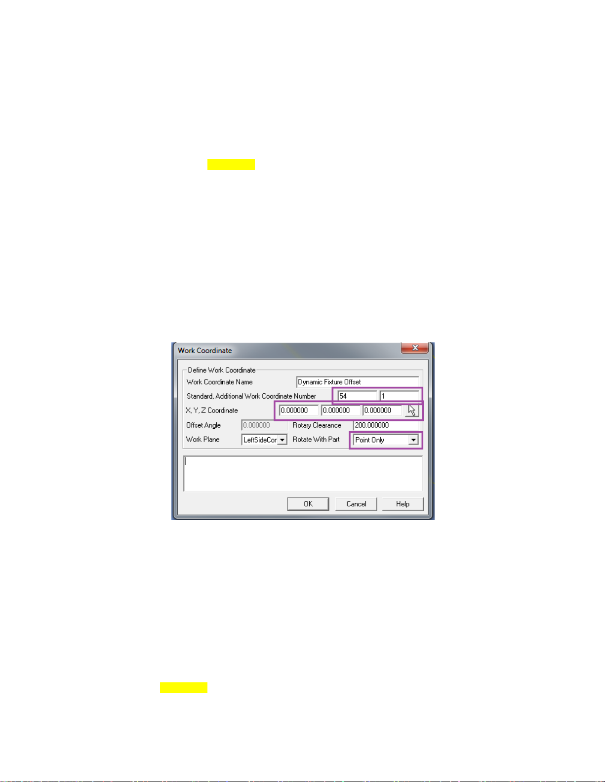
To define an Extended Work Coordinate set the Work Coordinate page as:
Page 6
6
Standard is set to 0 and Additional Work Coordinate Number is set to the P value. XYZ
is the location of the Work Coordinate in the file relative to the Work Plane. Rotate with
Part needs to be set to Point Only.
M06
G91 G28 Z0
G40 G80
G00 G90 G54.1 P1
M11
M69
G00 B0.0 C0.0
M10
M68
G17 G94 X-2.5 Y-6.538
G43 Z10.0 H02 S11650 M03
M08
2.3. Dynamic Fixture Offset Work Coordinate System
G54.2 P
To define a Dynamic Fixture Offset Coordinate System, set the Work Coordinate page
as:
Standard is set to 54 and Additional Work Coordinate Number is set to the P value.
XYZ is the location of the Work Coordinate in the file relative to the Work Plane. Rotate
with Part needs to be set to Point Only.
(SETTING FOR FIXTURE OFFSET G54.2)
G90 G10 L21 P1 X* Y* Z* B0 C0 ( X14.477 Y0.142 Z39.931 )
:
:
M06
G91 G28 Z0
G40 G80
G90 G54
G54.2 P1
M11
Page 7
7
M69
G00 B75.0 C0.0
M10
M68
G17 G94 X-1.164 Y11.441
G43 Z2.0 H02 S2653 M03
M08
Note that the command line for the Dynamic Fixture Offset will be output near the
beginning of the NC file.
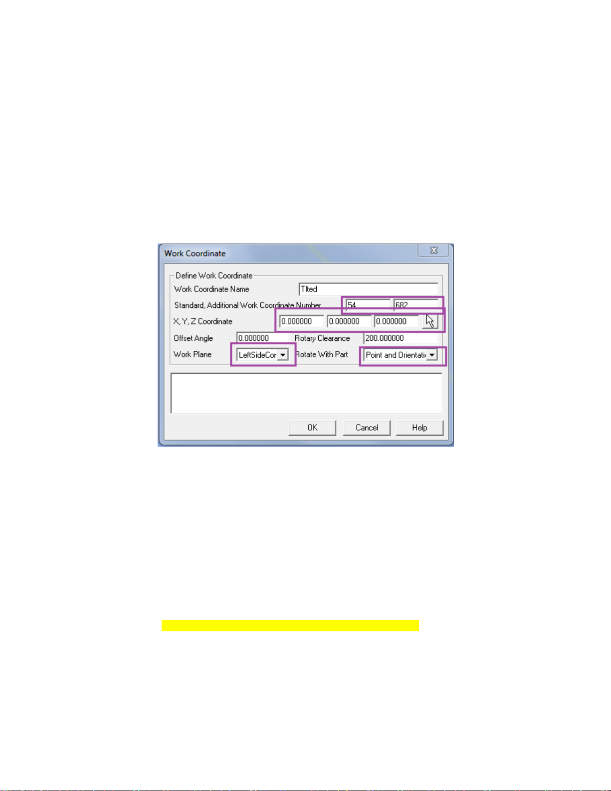
2.4 Tilted Plane Work Coordinate System G68.2
To define a Tilted Plane Work Coordinate System, set the Work Coordinate page as:
Standard is set to 54 and Additional Work Coordinate Number is set to 682. XYZ is the
location of the Work Coordinate in the file relative to the Work Plane. The Work Plane
is the Work Plane of the feature to be machined. Rotate with Part needs to be set to Point
and Orientation
M06
G91 G28 Z0
G40 G80
G00 G90 G54
M11
M69
G00 B75.0 C0.0
G49
G68.2 X14.477 Y0.142 Z39.931 I90. J75. K90.
G53.1
M10
M68
G17 G94 X0.961 Y-9.451
G43 Z2.0 H01 S5000 M03
M08
Page 8
8
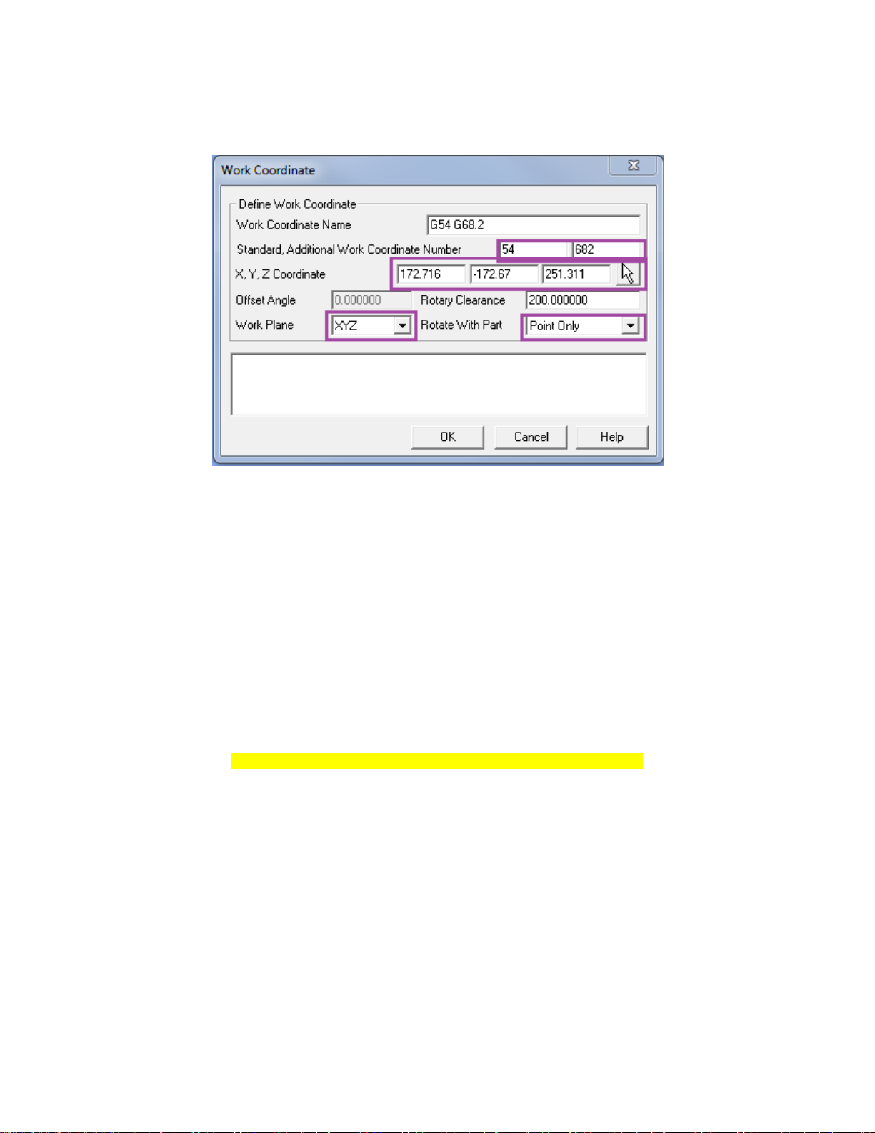
Using another Coordinate System, G68.2 can be defined in Esprit relative to P0. In this
case we define the Work Coordinate page as:
Standard can be set to an existing Work Coordinate and Additional Work Coordinate
Number is set to 682. XYZ is the location of the Work Coordinate in the file relative to
the current Work Plane which is XYZ. The XYZ Coordinate values in this scenario are
most commonly entered using the button on the far right, and digitizing the point in
Esprit where the new Work Coordinate will be located. The Work Plane is set to XYZ.
Rotate with Part needs to be set to Point Only.
M06
G91 G28 Z0
G40 G80
G00 G90 G54
M11
M69
G00 B40.0 C-45.0
G49
G68.2 X172.716 Y-172.67 Z251.311 I45. J40. K-90.
G53.1
M10
M68
G17 G94 X-3.175 Y2.432
G43 Z10.0 H02 S2005 M03
M08
2.5 Macro Work Coordinate System G65 P9681
This item is an option on your machine and may not be installed. Please contact Mori
Seiki to check on its configuration and availability.
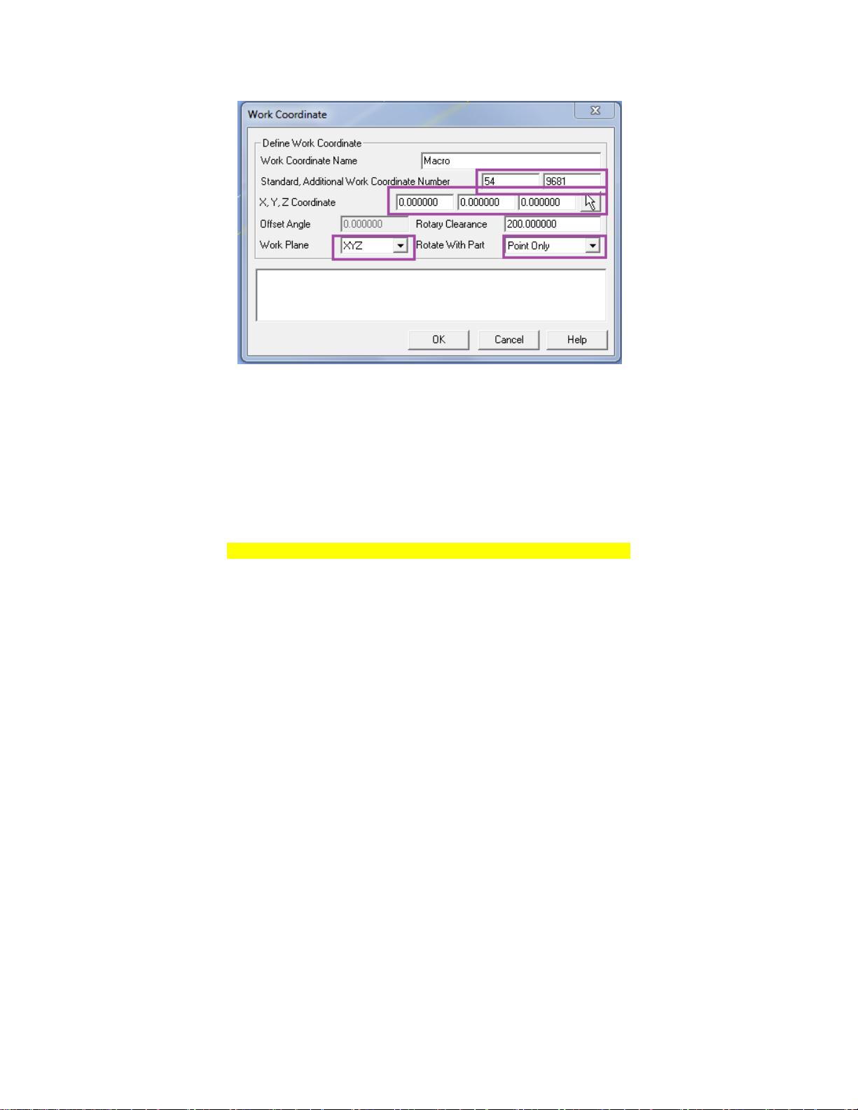
To define a Macro Work Coordinate System, set the Work Coordinate page as:
Page 9
9
Standard is typically set to 54, but it can be set to an existing Work Coordinate.
Additional Work Coordinate Number is set to 9681. XYZ is the location of the Work
Coordinate in the file relative to the current Work Plane which is XYZ. The Work Plane
is set to XYZ. Rotate with Part needs to be set to Point Only.
M06
G91 G28 Z0
G40 G80
G00 G90 G54
G65 P9681 X0.0 Y0.0 Z0.0 B90.0 C-120.0 M54. Q59.
G59
M11
M69
G00 B90.0 C-120.0
M10
M68
G17 G94 X-7.75 Y0.0G43 Z200.0 H02 S8722 M03
M08
3. Simultaneous 5 Axis Machining Settings
Creating 5x axis operations have some specific settings for the NMV machine.
3.1 Work Coordinate Setting
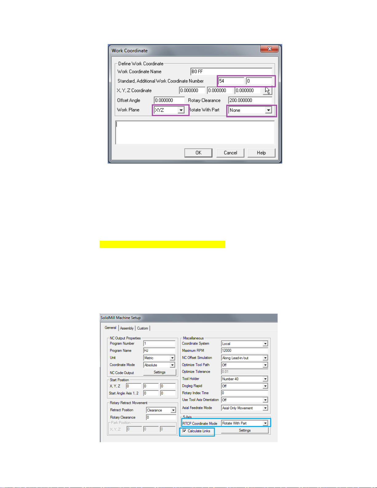
To define a Work Coordinate System for 5x milling operations, set the Work
Coordinate page as:
Page 10
10
Standard is the Work Coordinate Number, typically 54 and Additional Work Coordinate
Number is set to 0. The Work Plane is set to XYZ. Rotate with Part needs to be set to
None.
M06
G91 G28 Z0
G40 G80 G97
M11
M69
G00 G90 G54 G94 G17 X7.046 Y-9.132
G90 B0.0 C0.0
G49
G05 P10000
G43.4 H05 S1000 M03
G00 X7.046 Y-9.132 Z-20.819 B-45.0 C151.675
M08
3.1.1 Machine Setup Settings
Page 11
11
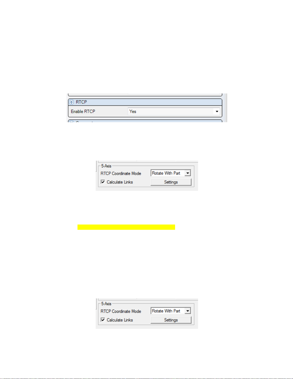
On the Machine Setup Page> RTCP Coordinate Mode Needs to be set to
Rotate With Part
On the Machine Setup Page> Calculate Links Box needs to be Checked.
3.2 RTCP
When creating 5x operations in Esprit for the NMV, remember to enable RTCP on the
operation page.
3.2.1 RTCP Type I (G43.4)
NMV machine supports two types of RTCP, Type I and Type II. To use Type I, set
Parameter 19696 #5=0. On the Machine Setup Page set RTCP Coordinate Mode to
Rotate with Part. Note we also recommend having Calculate Links checked.
M06
G91 G28 Z0
G40 G80 G97
M11
M69
G00 G90 G54 G94 G17 X7.046 Y-9.132
G90 B0.0 C0.0
G49
G05 P10000
G43.4 H05 S1000 M03
G00 X7.046 Y-9.132 Z-20.819 B-45.0 C151.675
M08
3.2.2 RTCP Type II (G43.5)
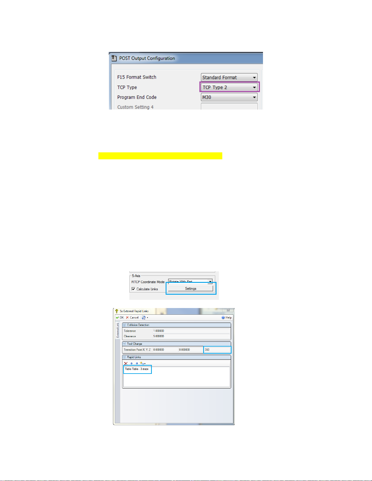
To use Type II, set Parameter 19696 #5=0 on the machine tool. On the Machine Setup
Page set RTCP Coordinate Mode to Rotate with Part. Note we also recommend having
Calculate Links checked.
In the Post Output Configuration Tool, on the Mori Seiki tool bar, select TCP Type 2.
Page 12
12
M06
G91 G28 Z0
G40 G80 G97
M11
M69
G00 G90 G54 G94 G17 X7.046 Y-9.132
G90 B0.0 C0.0
G49
G05 P10000
G43.5 H05 S1000 M03
G00 X7.046 Y-9.132 Z-20.819 I0 J0 K0
M08
3.3 Calculate Links Settings
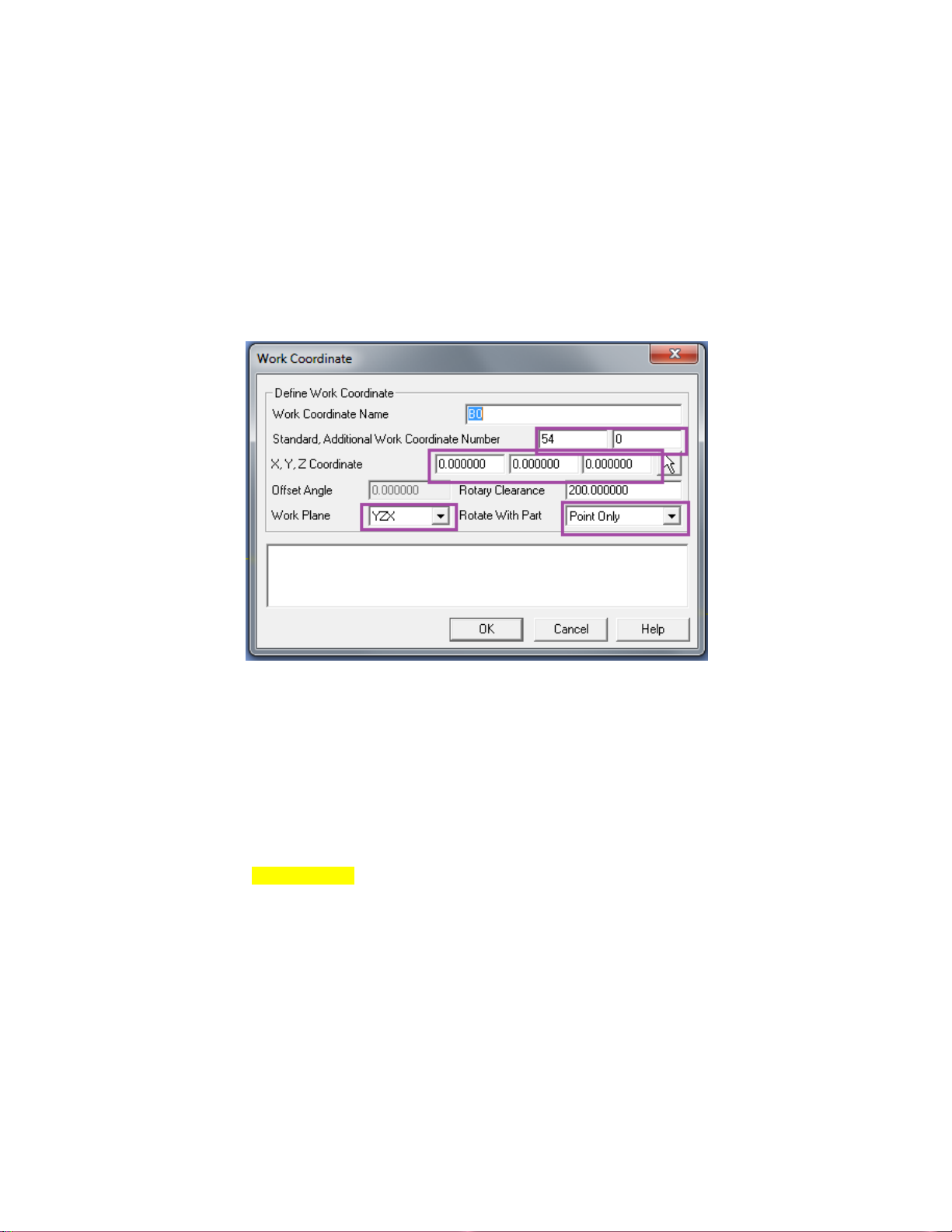
After the Links Box is Checked, the Settings button becomes active. Press the Settings
button to define your links. A recommended Z Transition Point value is something
larger than your part in any axis direction (i.e., outside the machining envelope of the
part). There are many different type of Rapid Links Available; Table-Table is simple,
straightforward and recommended. The Esprit Manual has through explanation of all the
Rapid Links.
Page 13
13
4. Turning Settings
Creating Turning operations and their Work Coordinates have special configuration
settings in Esprit.
4.1 Defining Turning Work Coordinates
4.1.1 B0 Turning
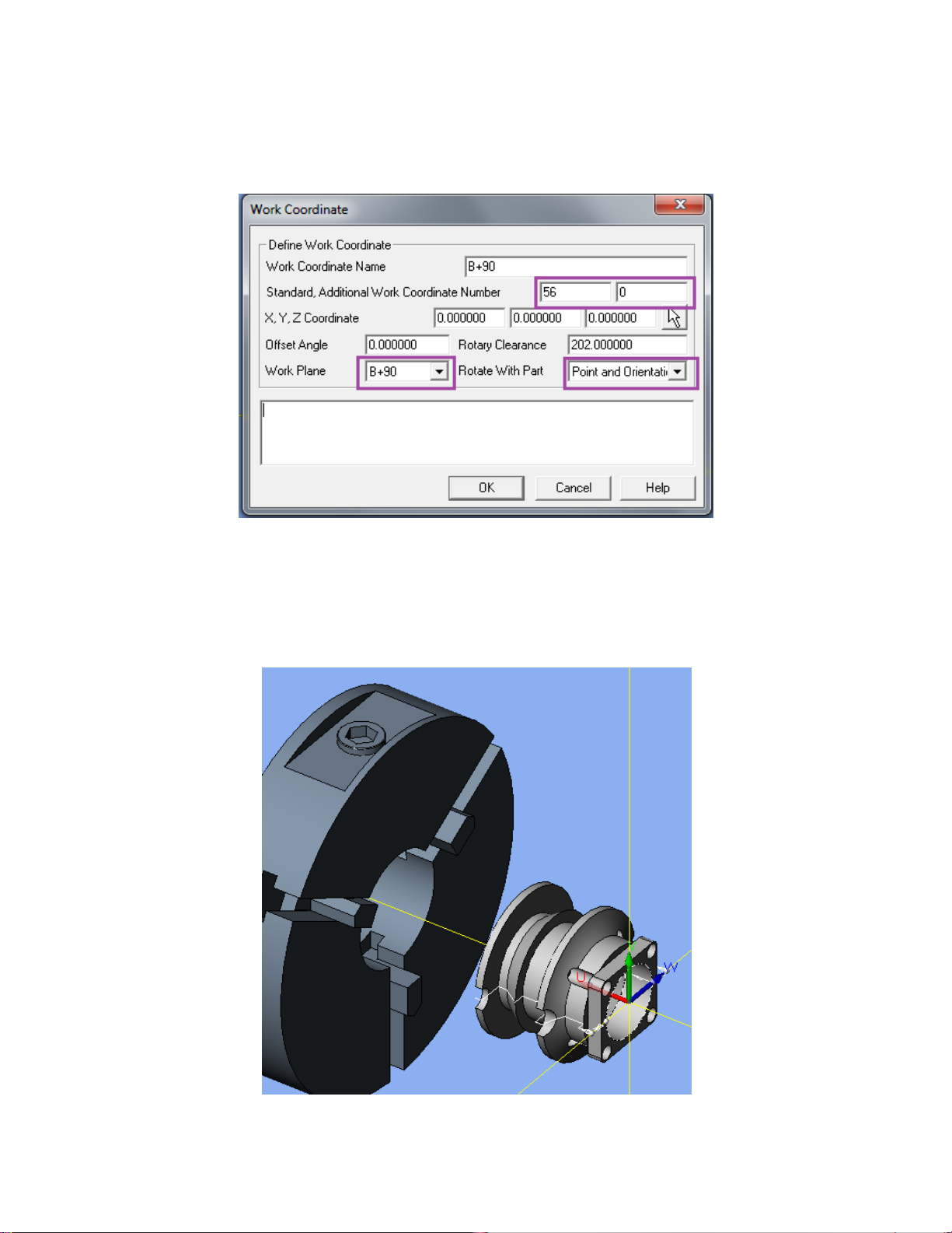
At B0 turning operations can exist on the OD, ID, and Face of the part. To define a Work
Coordinate System for B0 turning, set the Work Coordinate page as:
Standard is typically set to 54, but it can be set to any existing Work Coordinate.
Additional Work Coordinate Number is set to 0. XYZ is the location of the Work
Coordinate in the file relative to the current Work Plane which is YZX. If P0 is the face
of your part these values will be 0,0,0 The Work Plane is set to YZX. Rotate with Part
needs to be set to Point Only.
M06
G91 G28 Z0
G40 G80
G00 G90 G54
M69
G00 B0.0
M68
G49
G92 S500
G18 M11
G43.7 X22.99 Y0.0 H05
M304
G97 S500 M203
M08
Page 14
14
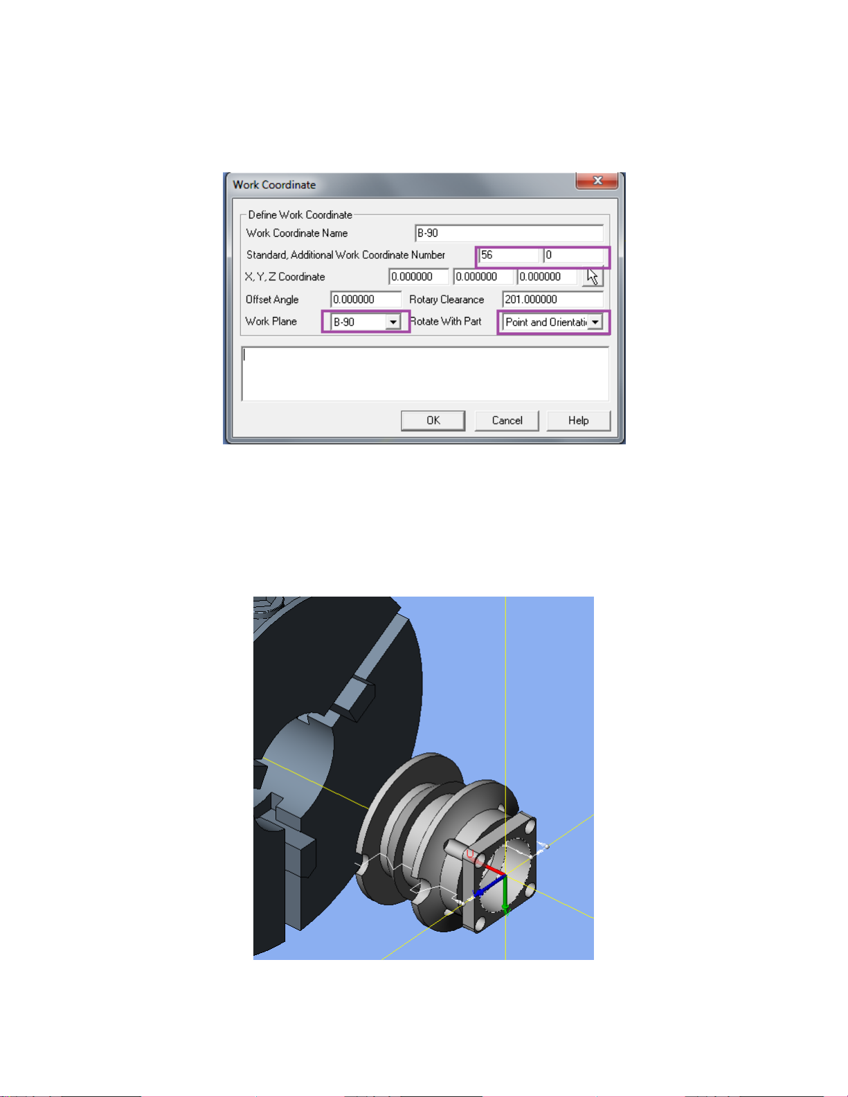
4.1.2 B90 Turning
At B90, turning operations can exist on the OD and Face of the part. To define a Work
Coordinate System for B90 turning, set the Work Coordinate page as:
Standard is typically set to 54, but it can be set to an existing Work Coordinate.
Additional Work Coordinate Number is set to 0. XYZ is the location of the Work
Coordinate in the file relative to the current Work Plane. If P0 is the face of your part
these values will be 0, 0, 0 Rotate with Part needs to be set to Point and Orientation.
The Work Plane in this example is set to B+90. Below is a picture of the B+90 work
plane in an Isometric view:
Page 15
15
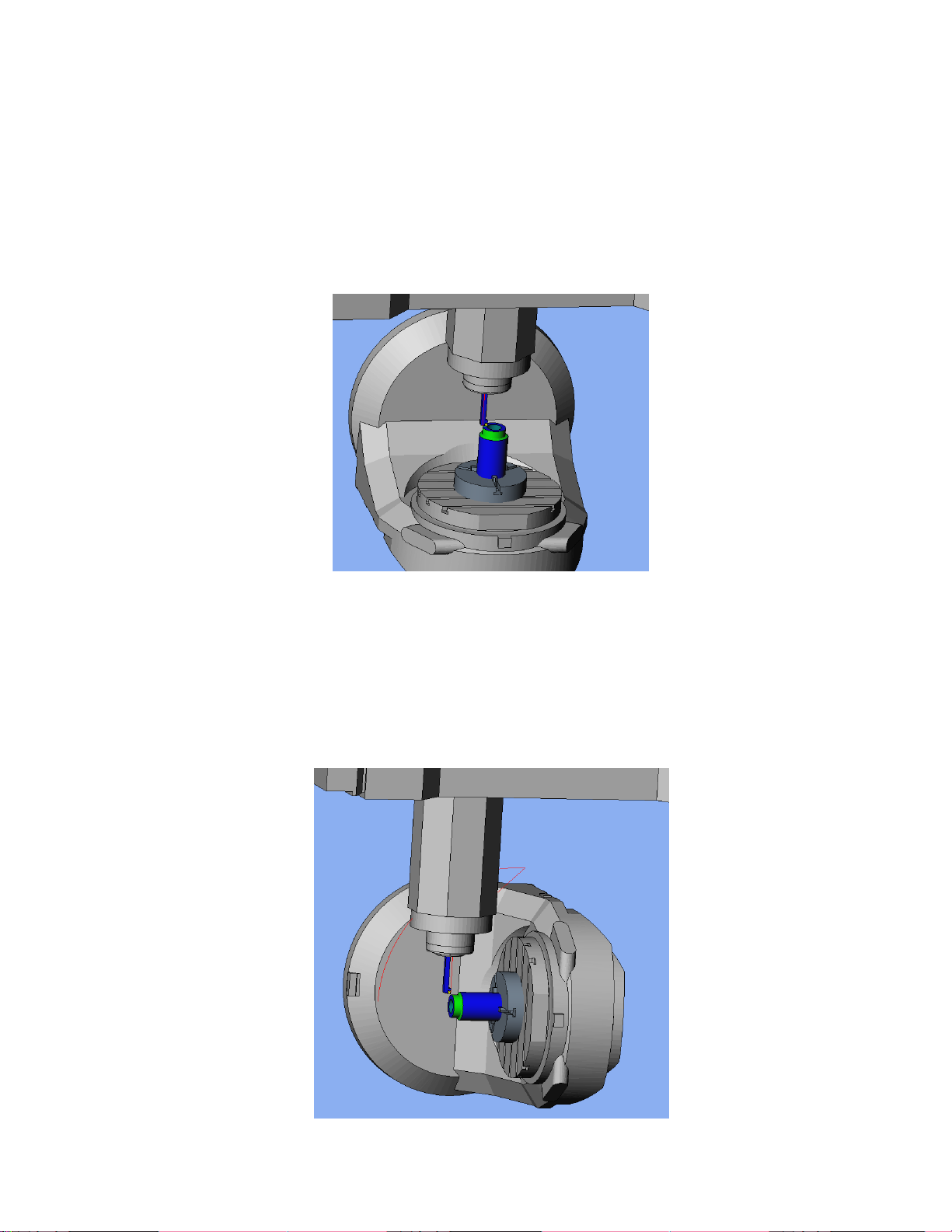
4.1.3 B-90 Turning
At B-90, turning operations can exist on the OD and Face of the part. To define a Work
Coordinate System for B-90 turning, set the Work Coordinate page as:
Standard is typically set to 54, but it can be set to any existing Work Coordinate.
Additional Work Coordinate Number is set to 0. XYZ is the location of the Work
Coordinate in the file relative to the current Work Plane. If P0 is the face of your part
these values will be 0,0,0 Rotate with Part needs to be set to Point and Orientation. The
Work Plane in this example is set to B-90. Below is a picture of the B-90 work plane in
an Isometric view.
Page 16
16
4.2 Defining Turning Tools
Defining turning tools and setting the tool orientation is important for the NMV. Tool
orientation on the Tool Definition page is set to 2H or 3H depending on the type of tool.
This setting can be overwritten on the operation page, where the orientation is set for that
operation only.
4.2.1 B0 Turning Tools
When creating a turning operation when the table is at B0, operations can be on the OD,
ID, and Face.
OD operations can have a tool orientation of 3H and 2H.
ID operations can have a tool orientation of 3H and 2H.
Face operations can have a tool orientation of 3H and 2H.
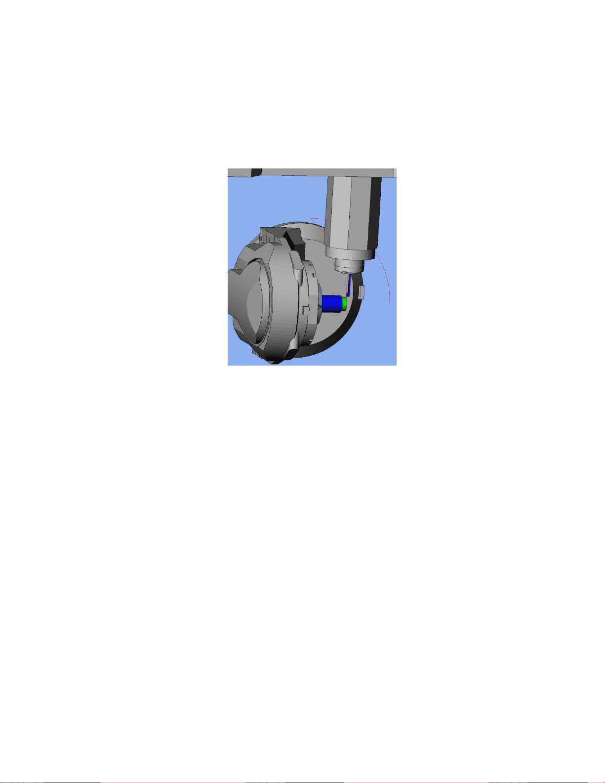
4.2.2 B90 Turning Tools
Page 17
17
For a B90 turning operation, operations can be on the OD and Face.
OD operations can have a tool orientation of 3V and 4V.
Face operations can have a tool orientation of 3V and 4V.
4.2.2 B-90 Turning Tools
For a B-90 turning operation, operations can be on the OD and Face.
OD operations can have a tool orientation of 3V and 4V.
Face operations can have a tool orientation of 3V and 4V.
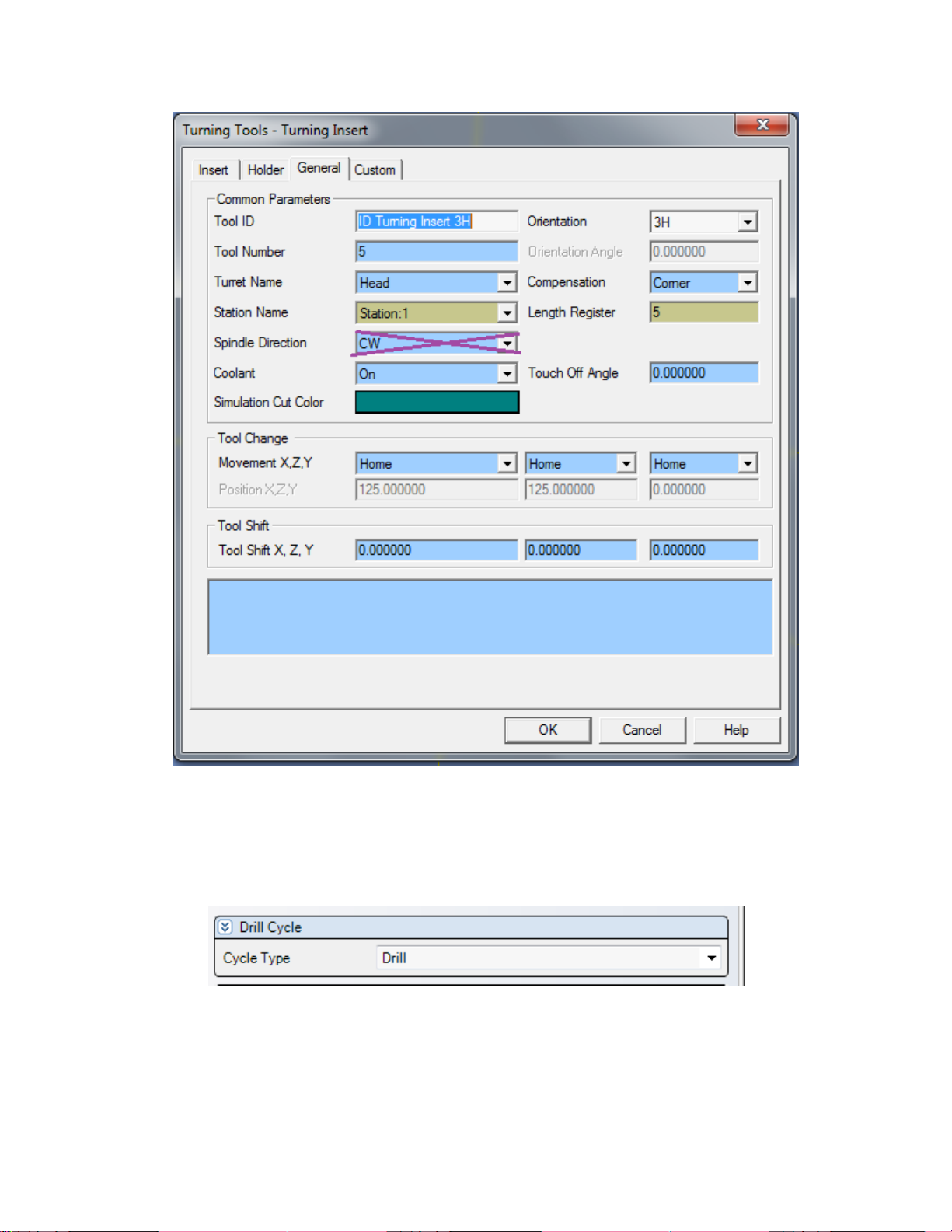
4.3 Spindle Direction for Turning Tools
The NMV post processor will automatically determine the direction of the spindle for
turning operations based on the orientation of the tool, the hand of the tool, the angle of
the table, and the type of cut. It is no longer necessary to set the Spindle Direction on the
Tool Page.
Page 18
18
5. Drill Cycles
Drilling, Boring and Tapping cycles on the NMV can be set using the Drill operation
page. Selecting Cycle Type on the Drill operation page determines the output in the NC
file.
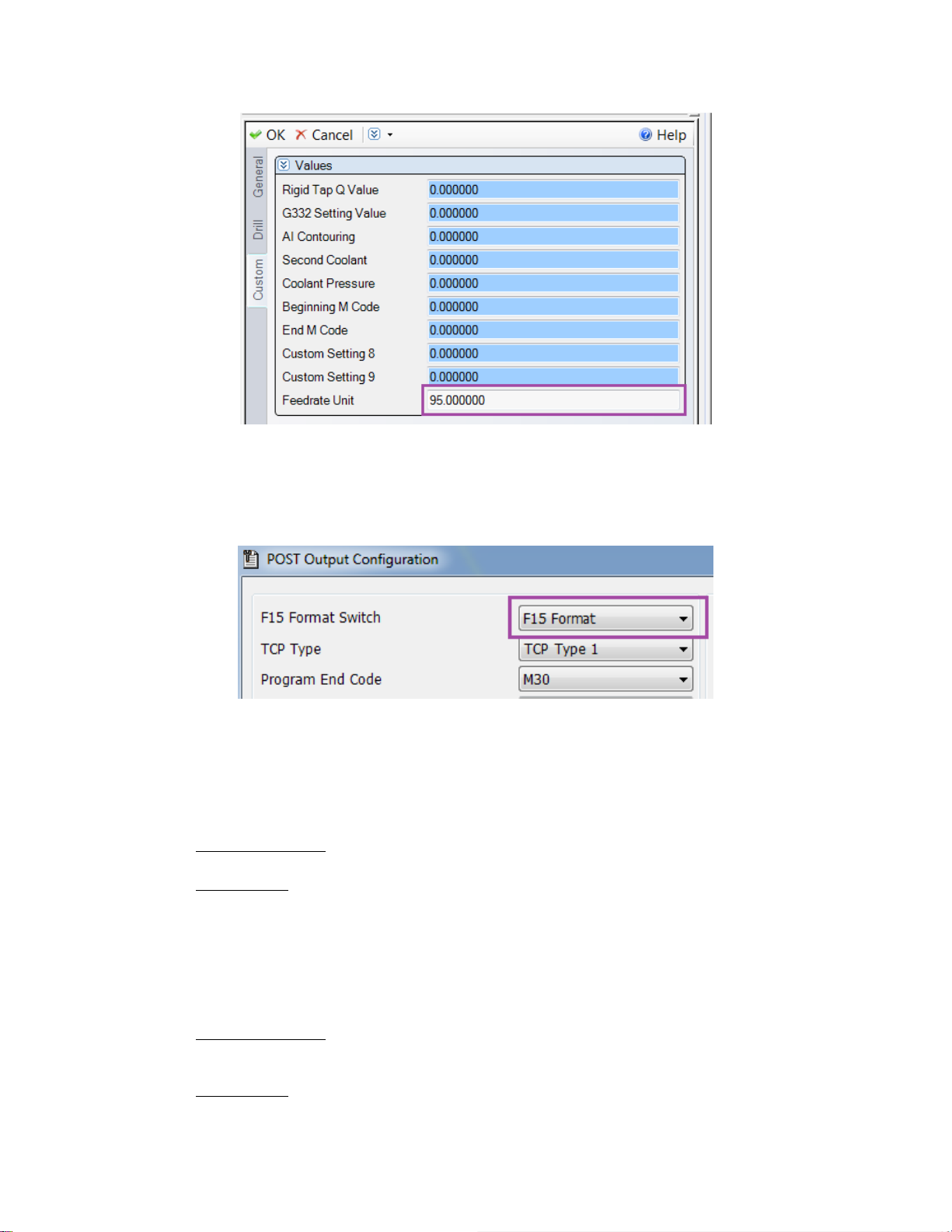
Any cycle can output the PM or PR feedrate. By default the PM feedrate is output. Enter
95 into Feedrate Unit on the Custom on the operation to output a G95 and a PR feedrate
value.
Page 19
19
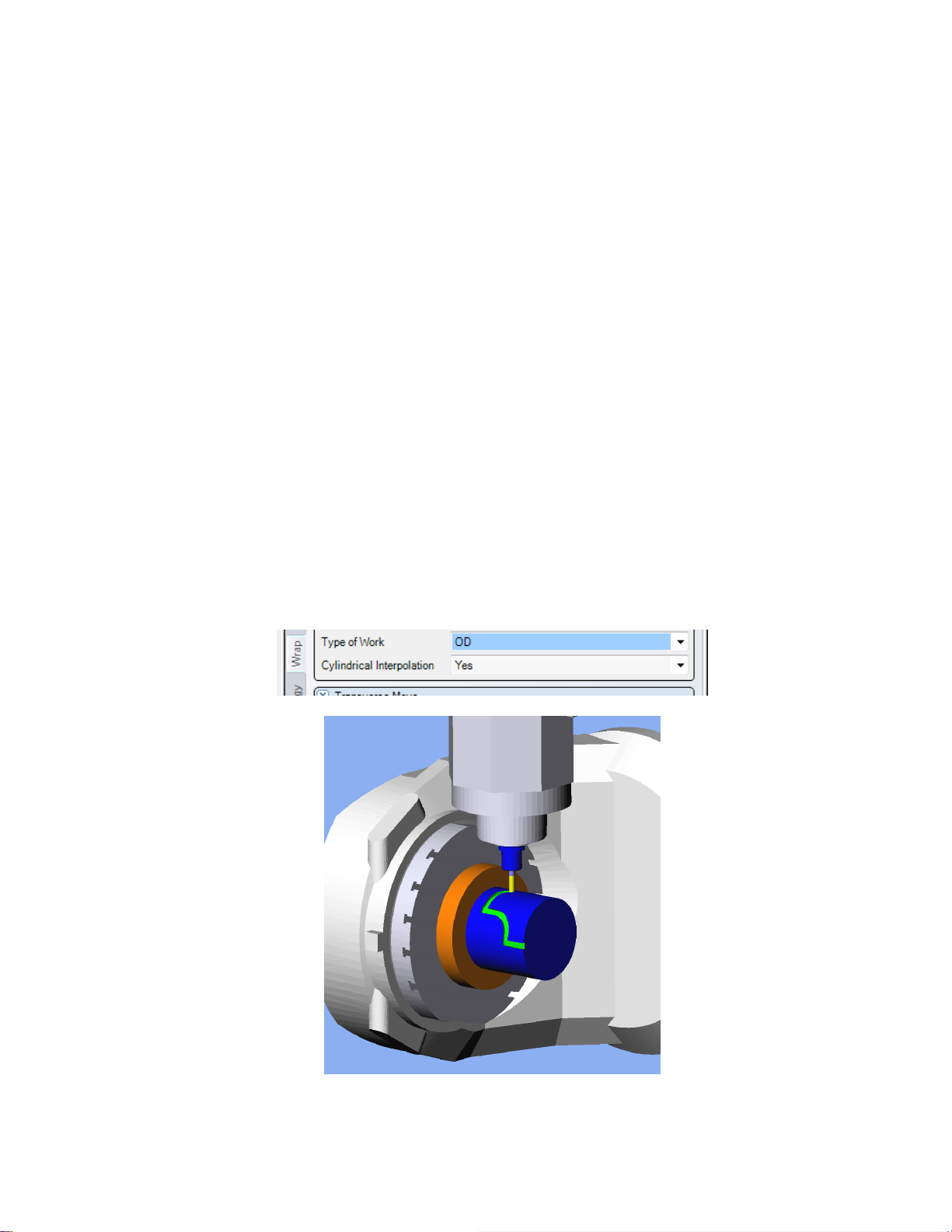
The NMV post can be set to output Standard Fanuc format(16/18) or F15 format.
Standard format is the default. To change to F15 format, select the Post Output
Configuration Tool, on the Mori Seiki tool bar, select F15 Format. Changing the format
changes the output of some of the drilling cycles.
5.1 Drill
G99 G81 Z-3.583 R2.0 F686.66
5.2 Peck
G99 G83 Z-11.73 R-3.0 Q16.0 F844.91
5.3 Tap
Standard Format:
G98 G84(74) Z-15.0 R-3.0 F796.0
F15 Format:
G98 G84.2(84.3) Z-15.0 R-3.0 F796.0
5.2 Bore
G98 G85 Z-18.862 R-3.0 F2958.85
5.3 Peck2
G99 G73 Z-38.627 R-3.0 Q10.0 F952.49
5.4 Tap2
Standard Format:
M29 S318
G98 G84(74) Z-36.935 Q235.0 R-3.0 F795.0
F15 Format:
G98 G84.2(84.3) Z-36.935 Q235.0 R-3.0 F795.0
Page 20
20
5.5 Bore2
G98 G86 Z-25.0 R-3.0 F8877.3
5.6 Bore3
G98 G87 Z-36.295 R-8.0 Q7.329 P500 F2958.85
5.7 Bore4
G98 G88 Z-18.006 R-3.0 P500 F8877.3
5.8 Bore5
G98 G89 Z-15.0 R-3.0 P500 F8877.3
5.9 Bore6
G98 G76 Z-21.75 R-3.0 P500 F4438.65
5.10 Bore7
G98 G82 Z-18.006 R-3.0 P500 F2958.85
5.2 Additional Drilling Notes
th
6. 4
Esprit supports wrap milling operations on the diameter or face of a part. Cylindrical and
Polar Interpolation can be used to shorten the length of the NC file.
Axis Wrap Milling Cycles
6.1 Cylindrical Interpolation
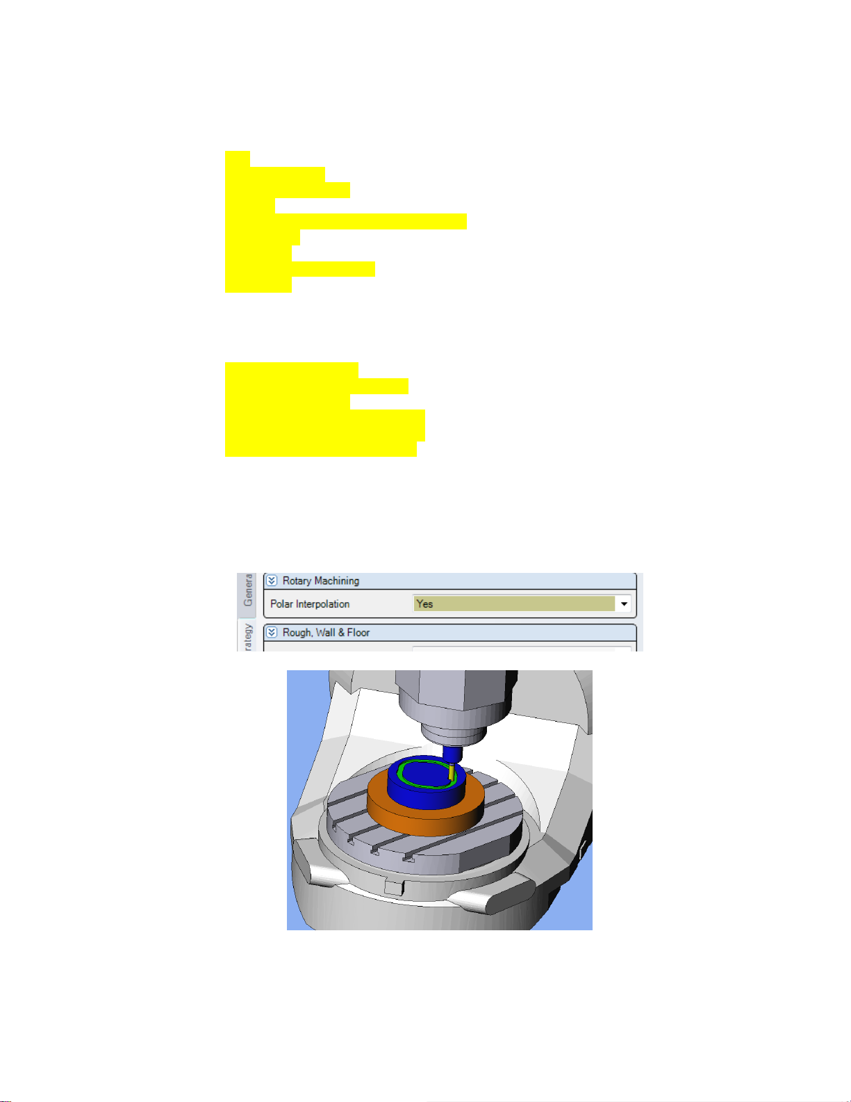
Cylindrical Interpolation is available on Wrap Contour and Wrap Pocket operations.
NC output with Cylindrical Interpolation ON:
Page 21
21
:
M08
M11
G07.1 C100.0
G01 Z75.0 F0.87
X191.3
G17 G03 X141.3 C193.006 R50.0
G01 X93.8
C182.005
G02 X43.8 C153.357
G01 X8.0
:
NC output with Cylindrical Interpolation OFF:
:
M08
G01 Z75.0 F0.144
X191.3 C164.358 F0.087
C164.431 F3.589
X191.299 C164.503 F3.589
X191.298 C164.611 F2.393
X191.296 C164.72 F2.393
:
6.2 Polar Interpolation
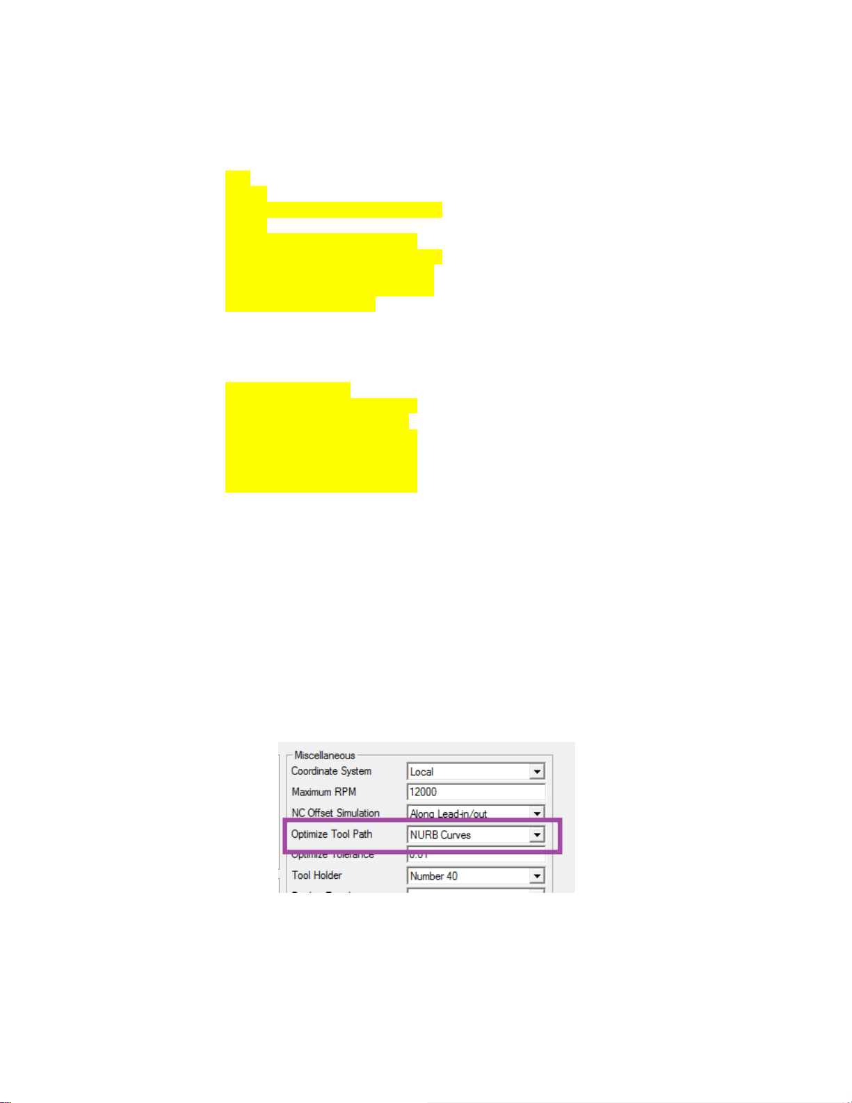
Polar Interpolation is available on Rotary Face Pocketing and Rotary Face
Contouring.
Page 22
22
NC output with Polar Interpolation ON:
:
M08
M11
G12.1
G01 X33.887 C-52.179 F50.0
Z-5.0
X41.836 C-57.381 F100.0
G02 X45.555 C-53.148 R20.0
G03 X37.187 C59.306 R70.0
G02 X31.874 C64.167 R20.0
G03 X-31.874 R40.0
:
NC output with Polar Interpolation OFF:
:
M08
G01 Z-5.0 F50.0
X62.424 C-56.914 F98.74
X62.631 C-56.831 F98.7
X62.839 C-56.749 F98.66
X63.046 C-56.666 F98.63
X63.254 C-56.585 F98.59
X63.461 C-56.504 F98.56
7. 3 Axis Freeform and SolidMill Cycles
Esprit has many different types of operation to create 3 axis operations.
7.1 NURB Output
The NMV post processor has NURB and non NURB Output. Select the type of output
you want on the Machine Setup Page> Optimize Tool Path. Optimize Tool Path needs
to be set before the operation is created. If you forget to set it before creating the
operation, simply rebuild the operation and current Optimize Tool Path setting will be
applied.
Page 23

23
NC output with NURB Output ON:
:
M08
Z7.581
M00
G04 P5000
G01 Z5.581 F26.26
G06.2 P4 K0 X38.343 Y20.251 Z5.581 R1. F140.06
K0 X37.908 Z6.974 F105.05
K0 X37.161 Z8.404
K0 X36.02 Z9.857
K.045 X34.336 Z11.822
K.05 X31.627 Z13.46
:
NC output with NURB Output OFF:
:
M08
Z7.581
M00
G04 P5000
G01 Z5.581 F26.26
X-38.093 Z6.307 F105.05
X-37.843 Z6.911
X-37.593 Z7.438
X-37.343 Z7.911
:
8. Coolant Codes
Coolant codes can be selected inside Esprit for output in the NC file. Up to two coolant
codes can be output per tool.
8.1 Primary Coolant Code
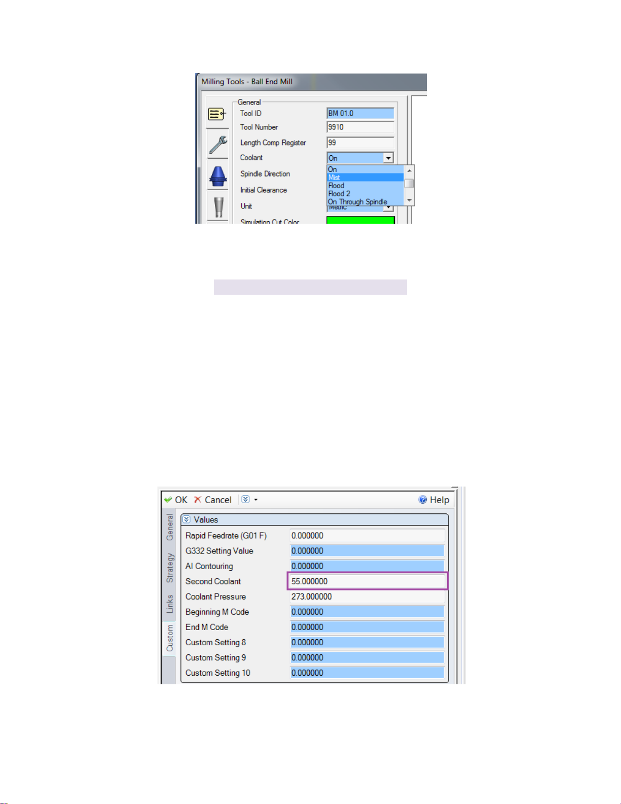
The primary coolant code is set by using the pull down on the tool page.
Page 24
24
Esprit Pull down
NMV M Code
On
M08
Mist
M51
Flood
M52
Flood 2
M53
On Through Spindle
M88
Mist Through Spindle
M55
Flood Through Spindle
M72
Flood2 Through Spindle
M80
Here is a chart showing the available coolant codes in Esprit and M codes they are
mapped to for the NMV machine.
8.2 Secondary Coolant Code
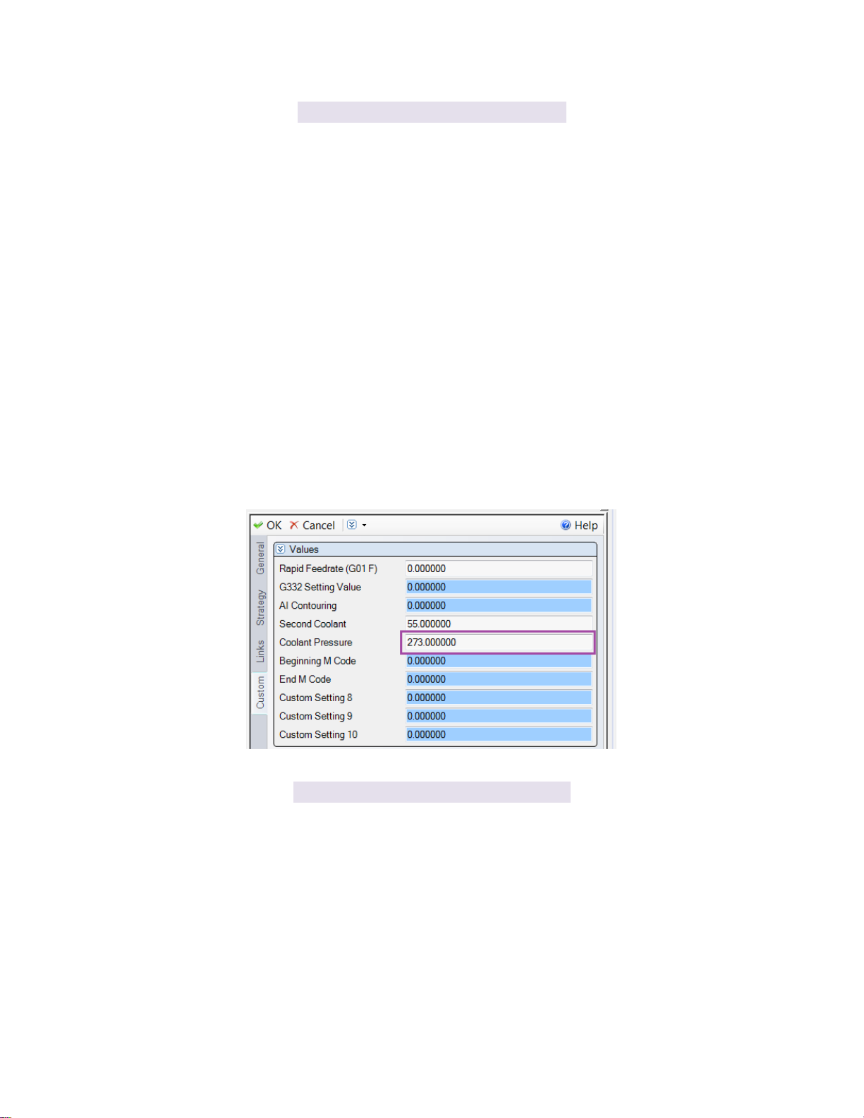
The secondary coolant code is set by using Second Coolant on the Custom Tab of the
operation page.
Here is a chart showing the available coolant codes in Esprit using Custom Code 4 and M
codes they are mapped to for the NMV machine.
Page 25
25
Second Coolant
NMV M Code
51
M51
52
M52
53
M53
55
M55
72
M72
80
M80
88
M88
164
M164
165
M165
226
M226
Coolant Pressure
NMV M Code
270
M270
271
M271
272
M272
273
M273
274
M274
275
M275
276
M276
277
M277
Note: When using Oil Hole Drill (M50), Sensor Air Blow (M53), Spindle Air Blow
(M164), Oil-Hole Air Blow (M165), Oil Mist Collector (M180), and Semi Dry (M226) as
the only coolant; the primary coolant type should be set to off.
8.3 Coolant Pressure Code
The coolant pressure code is set by using Coolant Pressure on the Custom Tab of the tool
page.
Here is a sample of NC code with the 3 coolant related codes highlighted.
Page 26
26
M11
M69
G00 B0.0 C0.0
M10
M68
M273
G17 G94 X-35.017 Y103.75
G43 Z2.0 H01 S7767 M03
M52
M55
G01 Z0.0 F4734.76
X0.046 F6313.02
9. Custom Codes
The Custom Codes in Esprit allow the user to set machine specific functions. Some
common to the operation pages are detailed here.
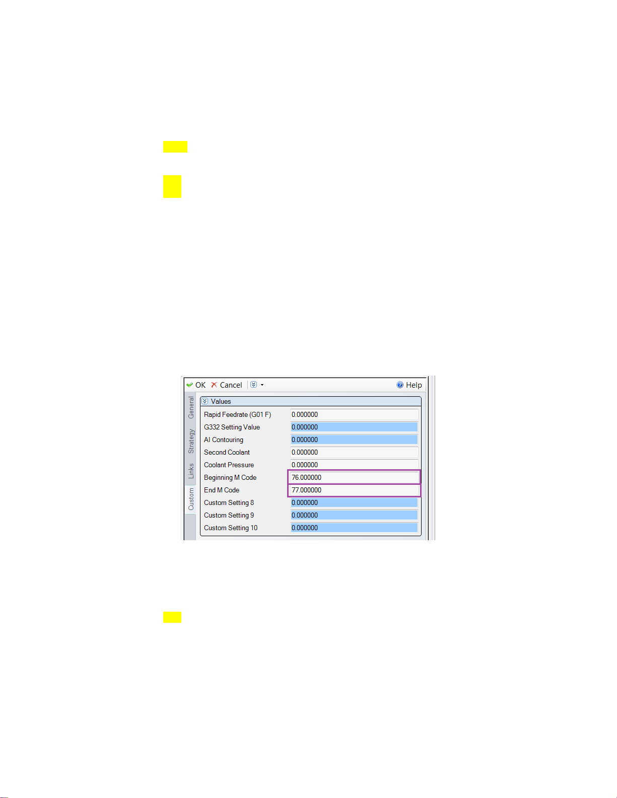
9.1 M Codes at the Beginning and End of an Operation
Custom codes can be used to output any M code near the beginning of an operation and
at the end of an operation. Beginning M Code defines the code at the beginning of an
operation and End M Code 7 can define one at the end.
M11
M69
G00 B0.0 C0.0
M10
M68
M76
G17 G94 X-35.017 Y103.75
G43 Z2.0 H01 S7767 M03
M08
G01 Z0.0 F4734.76
X0.046 F6313.02
G02 X46.987 Y92.5 R103.75
:
G01 X31.82
Page 27
27
G02 X0.046 Y-103.75 R103.75
AICC
AI Contouring
G05 P10000
1
G05.1 Q1
2
G05.1 Q3
3
G08 P1
4
G01 X-35.017
Z2.0 F4734.76
M77
M01
:
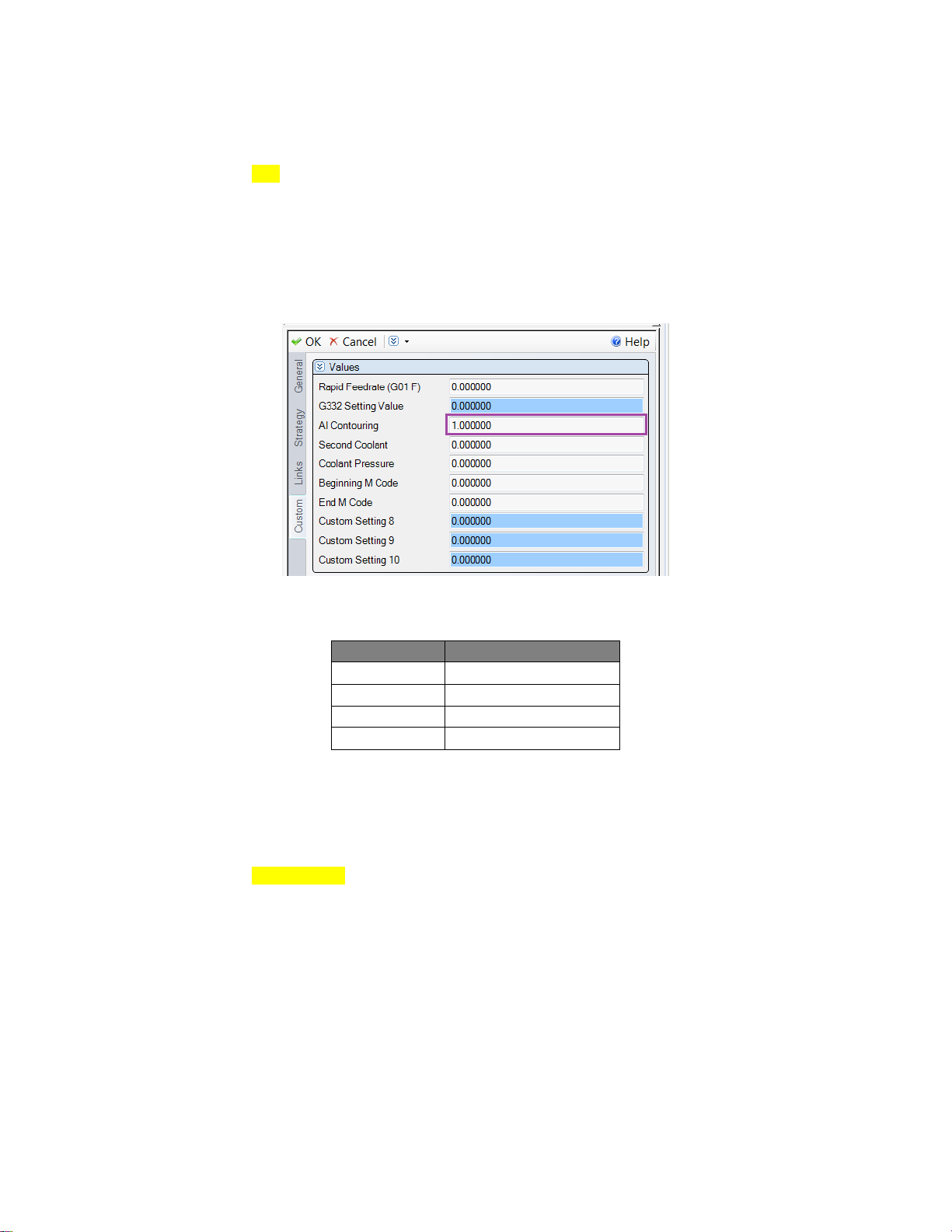
9.2 AI Contour Control
To use AI Contour Control, enter the corresponding value into AI Contouring on the
Custom tab of the operation page.
Here is a table defining the mapping.
Example NC showing the placement of the AI Code:
G00 B0.0 C0.0M10
M68
G17 G94 X-35.017 Y103.75
G05 P10000
G43 Z2.0 H01 S7767 M03
M08
G01 Z0.0 F4734.76
X0.046 F6313.02
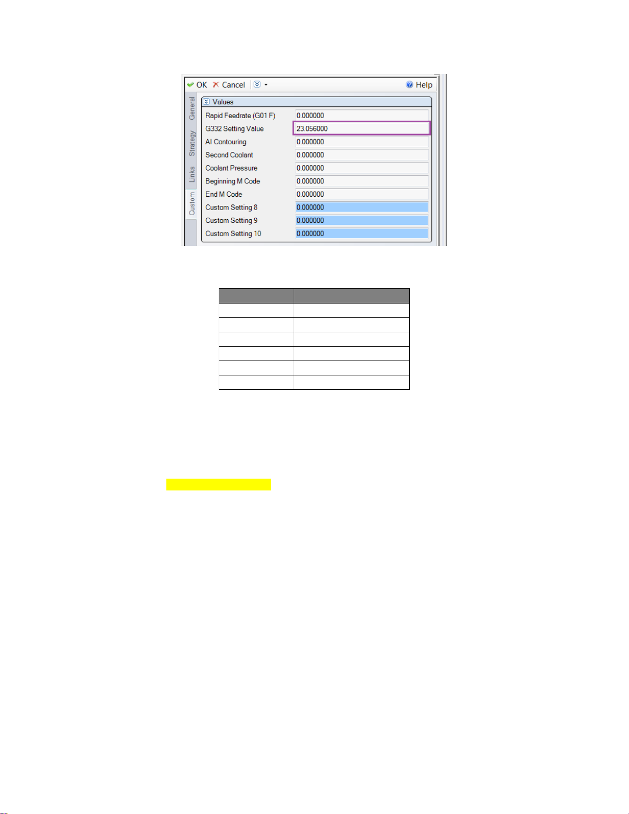
9.3 Cutting Mode (G332)
To use Cutting Mode during a cycle, place the corresponding value into G332 Setting
Value on the Custom Tab of the Operation Page. To use G332 with T, or T and A
parameters, integers cannot be entered. For a T only value output, enter a decimal value.
For a T and A values, enter the T value to the left of the decimal point, and the A value to
the right of the decimal point.
Page 28
28
Cutting Mode
G332 Setting Value
G332 R1
1
G332 R2
2
G332 R3
3
G332 R4
4
G332 T
.001-.999
G332 T A
1.001-200.999
Here is a table defining the mapping.
Example NC showing the placement of the AI Code:
G00 B0.0 C0.0
M10
M68
G17 G94 X-35.017 Y103.75
G332 T0.056 A23.0
G05 P10000
G43 Z2.0 H01 S7767 M03
M08
G01 Z0.0 F4734.76
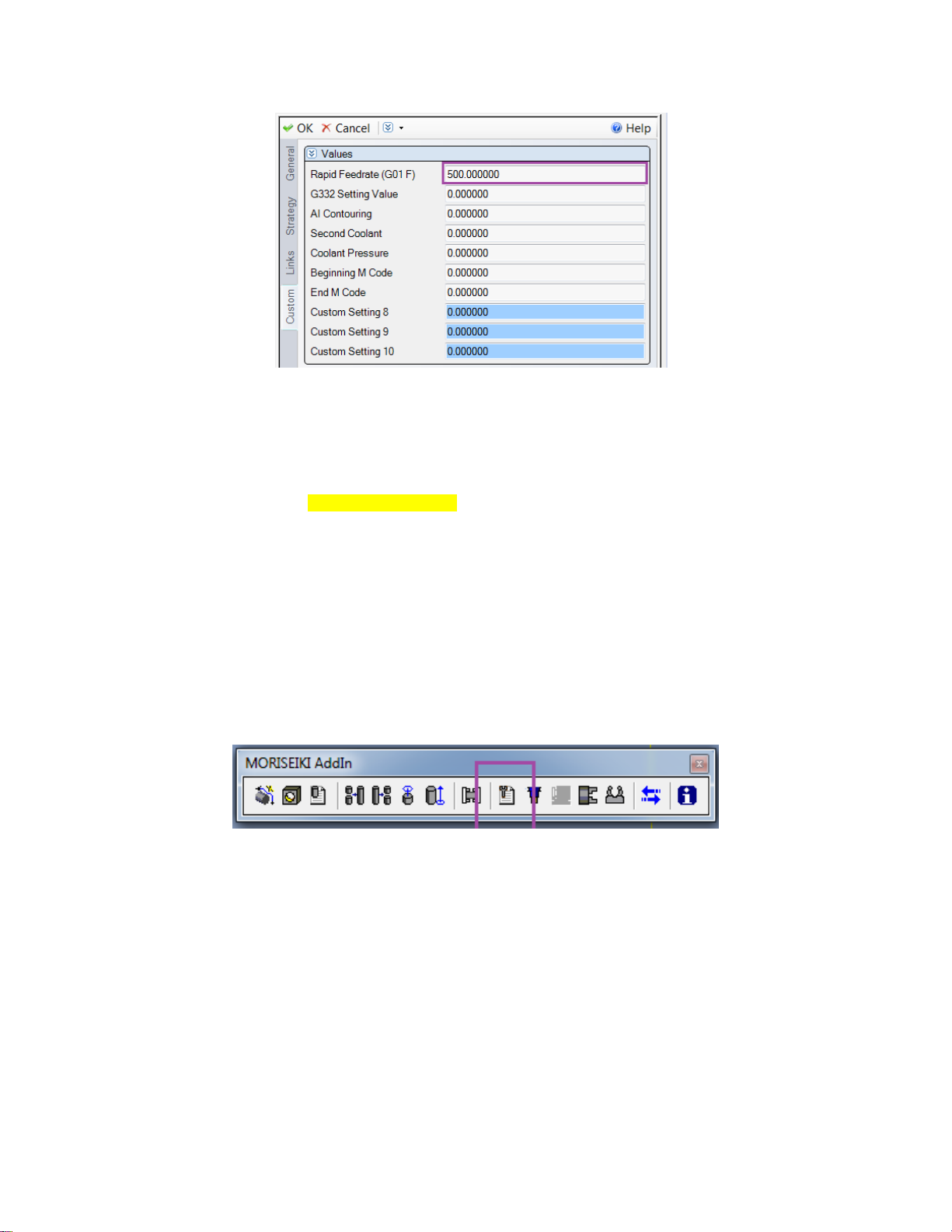
9.4 Rapid Feedrate (G01 F)
On the Custom Tab of the Operation Page, ‘Rapid Feedrate (G01 F)’ allows the user to
change rapid moves (G00) to feed moves (G01) for the entirety of the operation. By
entering a Feed value, the switch will be enabled with the number input as the Feed.
Page 29
29
G00 B0.0 C0.0
M10
M68
G17 G94 X115.0 Y100.0
G43 Z-3.0 H17 S7767 M03
M08
G01 Z-5.0 F500.0 // Rapid Move becomes a Feed Move
X-115.0 F6313.02
Z-3.0 F500.0
X115.0 Y92.5
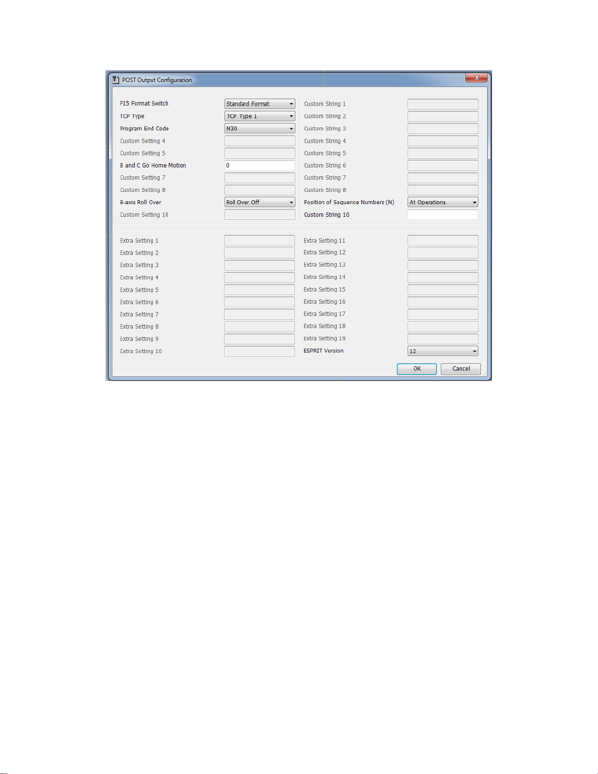
10. Post Output Configuration
The Post Output Configuration program on the Mori Seiki Addin toolbar is a tool for
setting values specific to your NMV machine. The Post Output Configuration program is
available for all Mori Seiki machines in Esprit, but the values may change depending on
the machine.
Page 30
30
10.1. F15 Format Switch
Switches from standard Fanuc format (16/18) to F15 format
10.2. TCP TYPE
Select the type of RTCP output for 5 axis operations; 1 (XYZ BC) or 2 (XYZ IJK).
10.3. Program End Code
Select the type of code for end of Program; M02, M30 or M99
10.4. B and C Go Home Motion
Allows the user to suppress some B and C home movements.
0: No moves are suppressed
1: Beginning of Operation moves Only
2: End of Operation moves Only
3: Both Begin and End Operation moves are suppressed
10.5. C-Axis Roll Over
Controls the output of the C axis.
Roll Over Off: C axis Values in the NC file will between -99999.999 and
+99999.999 (Parameter 1008 on Control must be set to 0 also).
Page 31
31
Roll Over On: C axis Values in the NC file will between -360. and +360.
(Parameter 1008 on Control must be set to 1 also).
10.6. Custom String 10
Allows the user to enter text commands to control other features of the machine. Please
see chapter 12 for a complete and detailed list.
10.7. ESPRIT Version
Displays the version of Esprit being used.
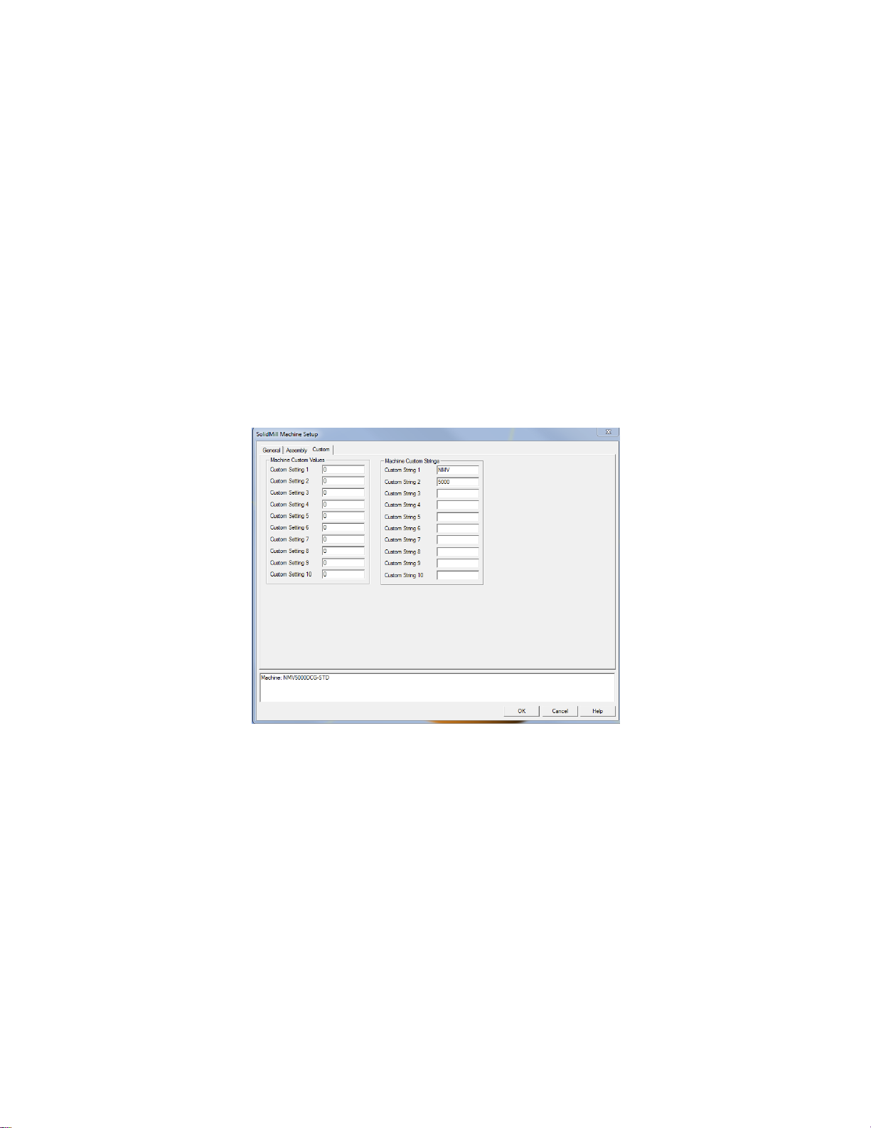
11. Machine Setup Custom Settings
Your system already has a configuration for the NMV in it which has all of the axis and
solids defined. In addition to the basic user settings on the General tab there are some
user configurable settings on the Custom Tab.
11.1 Fanuc Output Style
Custom Setting 1changes the NC code output format from Fanuc 16/18 to Fanuc 15. The
default (0) is 16/18. To change to Fanuc 15 enter a 1.
11.2 RTCP Output
Custom Setting 2 changes the RTCP output format from type I to type II. The default (0)
is type I. To change type II enter 435.
11.3 End of Program M code Output
Custom Setting 3 determines the M code output at the end of the NC file. The default (0)
is M30. Enter 99 to output M99, and anything else will output M02.
Page 32

32
11.4 Rollover for C Axis
Custom Setting 9 determines the rollover for C axis. The default (0) will output C axis
Values on the Machine will between -99999.999 and +99999.999 (Parameter 1008 on
Control Must be set to 0 also). Enter 1 and C axis Values on the Machine will between -
360. and +360. (Parameter 1008 on Control Must be set to 1 also).
11.5 Machine Name
Custom String 1 sets the name of the machine to be programmed. This should already be
set to NMV.
11.6 Machine Model Number
Custom String 2 sets the model number name of the machine to be programmed. The
NMV post processor supports 1500, 3000, 5000, and 8000 machines.
11.7 Tool Holder Type
Custom String 3 sets the tool holder type on the name of the machine to be programmed.
The NMV post processor supports DCG, DCG-40 and DCG-50. This does not affect the
output of the post.
11.8 TOOLTABLE
Entering TOOLTABLE into Custom String 10 creates a listing of all the tools used in the
Esprit file at the beginning of the NC file.
%
O1007 ( NMV_SAMPLE 7 )
(ESPRIT)
( MACHINE: NMV5000 WITHOUT TURNING OPTION)
(MACHINE: NMV5000DCG-STD)
(POST PROCESSOR : MoriSeikiNMV-2011-9-22)
(10/28/2011 4:10:13 PM)
(T7 H7 DR 02.5)
(T53 H53 DR 22.5)
(T18 H18 LFTHND 24)
(T6 H6 DR 0.689 in)
(T21 H21 TD M20 x 2.5)
(T4 H4 DR 0.196)
(T19 H19 LFTHND 6)
M200 (CHIP CONVEYOR START)
G49 G00 G21 G40 G80 G94
M05
T7
G91 G28 Z0
M11
M69
G91 G28 B0 C0
Page 33
33
11.9 StopTCOnly
By default, the NMV post will output a stop code ‘M01’ at the end of every operation.
Entering StopTCOnly (stop code for tool changes only), into Custom String 10 will tell
the post to only output the stop code at the end of an operation when a tool change will
occur. This data is not case sensitive.
11.10 NTCOnly
By default, the NMV post will output an N block at the beginning of every operation.
Entering NTCOnly (N block for tool changes only), into Custom String 10 will tell the
post to only output an N block at the beginning of an operation when a tool change
occurs. This data is not case sensitive.
12. Rotary Retract Movement Setup
Retract Position on the Machine Setup lets the user set the retract location of the tool
when the part is indexing between 2 operations. Currently the NMV supports Clearance
and Tool Change.
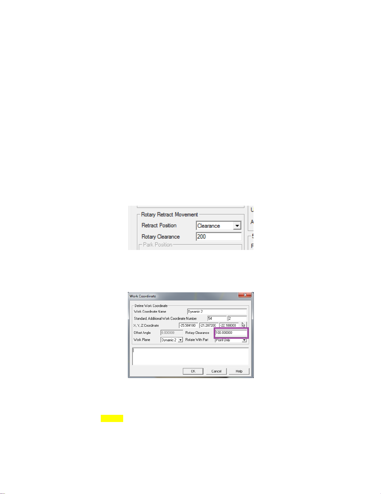
12.1 Clearance
If the Retract Position is set to Clearance, the tool will retract to the Rotary Clearance
value set on the active Work Coordinate page.
:
Y-21.469
Z24.188 F66.3
G00 Z50.0
Z100.0
G49
G54.2 P0
M01
Page 34

34
N2 (FACING 33,0 -1 DIFF W/O )
(EM 18.0 T2 H0 )
G90 G54
G54.2 P2
M11
M69
G00 B33.69 C0.0
M10
M68
G17 G94 X21.927 Y-73.965
G43 Z50.0 H0 S884 M03
M08
Z24.188
G01 Z22.188 F66.3
Y-6.051 F132.6
:
12.2 Tool Change
If the Retract Position is set to Tool Change, the tool will be sent home using ‘G91 G28
Z0 ; G90 G53 X__ Y0. The Rotary Clearance value set on the Work Coordinate page
will not be used. The X value is a safe position based on the angle of your table.
:
Y-21.469
Z24.188 F66.3
G00 Z50.0
G91 G28 Z0
G90 G53 X495.0 Y0.0
G49
G54.2 P0
M01
N2 (FACING 33,0 -1 DIFF W/O )
(EM 18.0 T2 H0 )
G91 G28 Z0
G90 G53 X5.0 Y0.0
G90 G54
G54.2 P2
M11
M69
G00 B33.69 C0.0
M10
M68
G17 G94 X21.927 Y-73.965
G43 Z50.0 H0 S884 M03
M08
Z24.188
G01 Z22.188 F66.3
Y-6.051 F132.6
:
Page 35
35
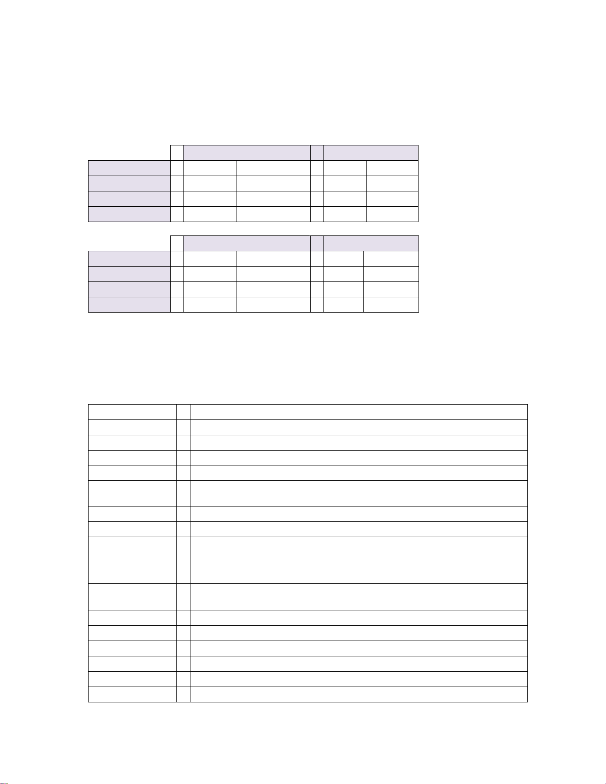
12.2.1 X Safe Positions
NMV 1500
NMV 3000
Table Angle
Metric
Inch
Metric
Inch
-135 --> -30
X415
X16.3385
X495
X19.4882
-30 --> +30
X240
X9.4488
X275
X10.8267
+30 --> +135
X5
X.1969
X5
X.1969
NMV 5000
NMV 8000
Table Angle
Metric
Inch
Metric
Inch
-135 --> -30
X725
X28.5433
X1195
X47.0471
-30 --> +30
X365
X14.3700
X600
X23.622
+30 --> +135
X5
X.1969
X5
X.1969
Custom Setting 1
Switches from standard format to F15 format: 0 is standard 1 is F15
Custom Setting 2
Turns on TCP type 2: 435 outputs TCP Type 2; 0 Outputs Type 1
Custom Setting 3
Switches Between M30 and M02: 0 is M30; 1 is M02
Custom Setting 4
Custom Setting 5
Custom Setting 6
Suppress B and C Home Movements; 0: None , 1: Beginning of Operation
Only, 2: End of Operation Only, 3: Both Begin and End
Custom Setting 7
Custom Setting 8
Custom Setting 9
Rollover for C Axis; 0: Caxis Values on the Machine will between -
99999.999 and +99999.999 (Parameter 1008 on Control Must be set to 0
also) 1: Caxis Values on the Machine will between -360. and +360.
(Parameter 1008 on Control Must be set to 1 also)
Custom Setting
10
Custom String 1
NMV
Custom String 2
1500, 3000, 5000, or 8000
Custom String 3
DCG, DCG-40 or DCG-50
Custom String 4
Custom String 5
Custom String 6
The safe X location that the tool moves to is determined the model of your machine, the
angle of the table, and unit of the NC file. Here is a simple chart showing the safe
positions.
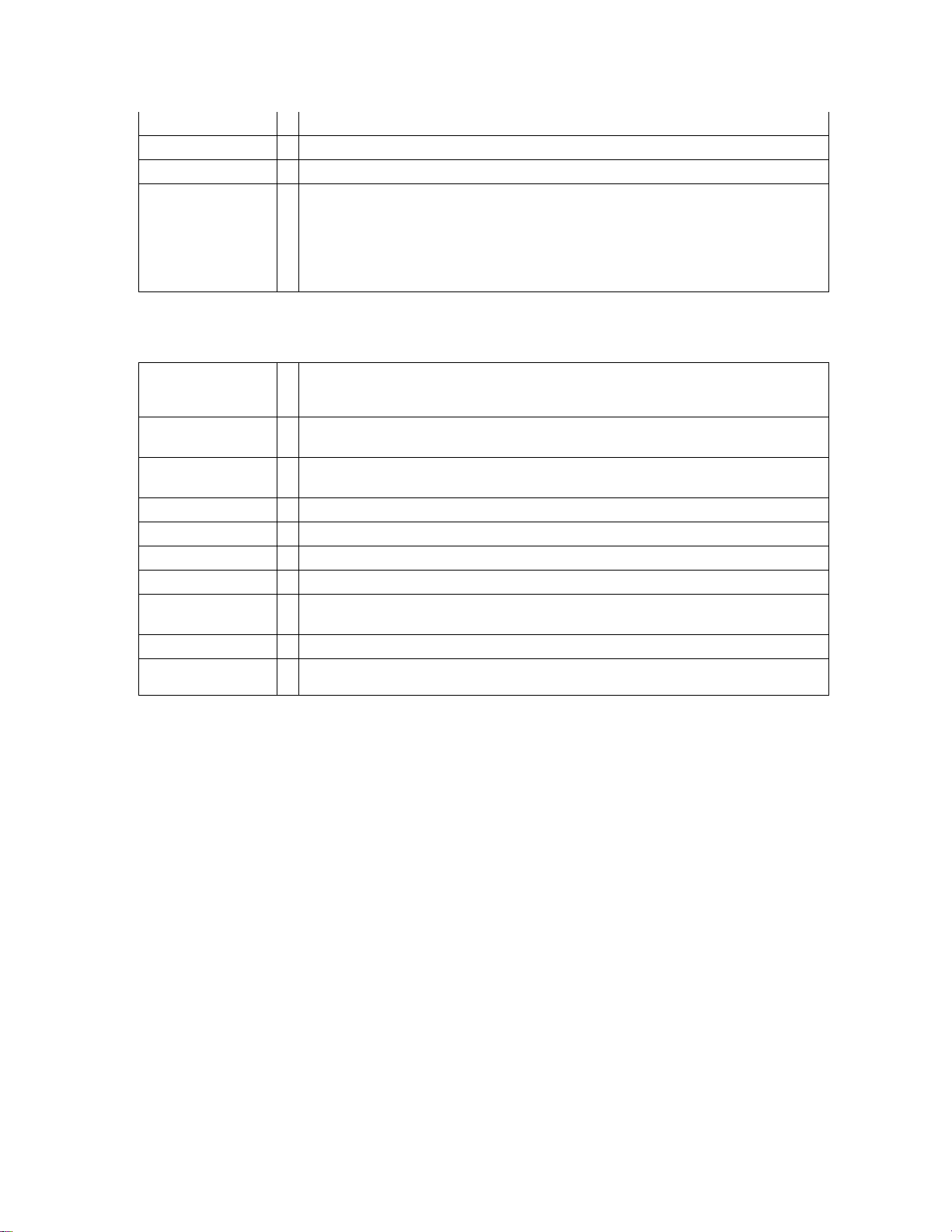
13. Custom Settings Reference List
Here is a list of all of the Custom Settings for the NMV post processor.
13.1 Machine Setup
Page 36
36
Custom String 7
Custom String 8
Arc Output; IJK: IJK, IJKR: IJK with (Rvalue), blank: R
Custom String 9
Custom String 10
TOOLTABLE; Outputs a Listing of Tools at the top of the NC file
NTCOnly ; Limits the Output of N blocks for operations which start with a
Tool Change
StopTCOnly; Ouputs M01 only for Tool Changes
COOLANTORDER1; moves the position of the First Coolant to before the
first movement of the operation
Custom Setting 1
For Tapping Cycles: Q-Value for synchronized tapping;
For Contouring type operations, = 0 Rapid Moves output, <>0 Feedrate
moves are output with a G01 and the enter value as a feedrate.
Custom Setting 2
Cutting Mode G332; Value Entered as an R value(integer) or as T and A
values(real)
Custom Setting 3
AI Contouring; 0:Off, 1: G05 P10000, 2:G05 Q1, 3:G05.1 Q3 X0 Y0 Z0,
4:G08 P1
Custom Setting 4
Secondary Coolant Codes; Value Entered Appears as M Code
Custom Setting 5
Coolant Pressure Levels ; Value Entered Appears as M Code
Custom Setting 6
Beginning of Operation M Code; Value Entered Appears as M Code
Custom Setting 7
End of Operation M Code; Value Entered Appears as M Code
Custom Setting 8
Shift Value for Continuous Baxis Contouring; Entered value is the amount
of Shift
Custom Setting 9
Custom Setting
10
Sets the Feedrate Unit for Drilling Cycles. 95=G95.
13.2 Operation Page
13.3 Tool Page
Currently no Custom Settings are being used on the Tool Page.
 Loading...