

Page 1

Page 2

ECI Multi Functional Weighing Controller Operating Manual
Esit Technical Support
Esit Support Line for Turkey
GSM : 0533 732 15 74
Email: [email protected]
Istanbul
Phone: Direct Line 0216 585 18 88 / 0216 585 18 18 Extension: 141 /142
Fax : 0216 585 18 89
Hendek
Phone: 0264 614 16 41 / 0264 614 16 42
Fax : 0264 614 16 43
Izmir
Phone: 0232 433 02 99
Fax : 0232 433 12 42
Ankara
Phone: 0312 397 01 10
Fax : 0312 397 07 73
Adana
Phone 0322 428 11 71
Fax : 0322 428 11 72
Esit Istanbul Head Office
Address Nişantepe Mahallesi Handegül Sokak No:6 Çekmeköy 34794 Istanbul
Phone: 0216 585 18 18
Fax : 0216 585 18 19
E-mail: [email protected]
Page 2
Page 3

ECI Multi Functional Weighing Controller Operating Manual
Page 3
Page 4

ECI Multi Functional Weighing Controller Operating Manual
1 Considerations
• Do not power-up the device before making sure that the device connections are made according to this
manual.
• Do not open the case or disconnect-insert the connections before disconnecting the device from the power
source.
• Note that the load cell and communication cables are not very close to the energy lines.
• Note that the cables are not crushed.
• Operate the device within the stated temperature range.
• The device has been developed for indoor use. Do not expose sunlight, rain and other external factors.
Page 4
Page 5

ECI Multi Functional Weighing Controller Operating Manual
Table of Contents
1 Considerations ........................................................................................................................................................... 4
2 Introduction .............................................................................................................................................................. 15
3 Physical Dimensions ................................................................................................................................................ 17
4 Specifications........................................................................................................................................................... 19
4.1 Technical Specifications .................................................................................................................................... 19
4.2 Use Properties................................................................................................................................................... 20
5 Installation and Connections .................................................................................................................................... 22
5.1 Standard Modules ............................................................................................................................................. 24
5.1.1 Slot1: Terminal (Supply and Communication Module) ................................................................................. 25
5.1.2 Slot2: Weighing (Load Cell) Module ........................................................................................................... 28
6 Screenshots ............................................................................................................................................................. 32
6.1 Weighing Main Screen ...................................................................................................................................... 32
6.1.1 Screen Layout ............................................................................................................................................. 33
Page 5
Page 6

ECI Multi Functional Weighing Controller Operating Manual
6.1.2 Symbols ...................................................................................................................................................... 33
6.1.3 Keys............................................................................................................................................................ 35
6.2 Menu Screen ..................................................................................................................................................... 36
6.2.1 Screen Layout ............................................................................................................................................. 36
6.2.2 Symbols ...................................................................................................................................................... 37
6.2.3 Keys............................................................................................................................................................ 38
6.3 Change Parameter Screen (Numeric or Alpha-Numeric Entry Type) ................................................................. 39
6.3.1 Screen Layout ............................................................................................................................................. 39
6.3.2 Symbols ...................................................................................................................................................... 40
6.3.3 Keys............................................................................................................................................................ 40
6.4 Change Parameter Screen (Selective Type) ...................................................................................................... 42
6.4.1 Screen Layout ............................................................................................................................................. 42
6.4.2 Symbols ...................................................................................................................................................... 43
6.4.3 Keys............................................................................................................................................................ 43
Page 6
Page 7

ECI Multi Functional Weighing Controller Operating Manual
6.5 Ordered Menu Screen ....................................................................................................................................... 44
6.5.1 Screen Layout ............................................................................................................................................. 44
6.5.2 Symbols ...................................................................................................................................................... 45
6.5.3 Keys............................................................................................................................................................ 46
6.6 Confirmation Screen .......................................................................................................................................... 47
6.6.1 Screen Layout ............................................................................................................................................. 47
6.6.2 Symbols ...................................................................................................................................................... 48
6.6.3 Keys............................................................................................................................................................ 48
6.7 Message Screen ............................................................................................................................................... 49
6.7.1 Screen Layout ............................................................................................................................................. 49
6.7.2 Symbols ...................................................................................................................................................... 50
7 Using the Device ...................................................................................................................................................... 52
7.1 Program Selection ............................................................................................................................................. 53
7.1.1 Start-up Screen ........................................................................................................................................... 53
Page 7
Page 8

ECI Multi Functional Weighing Controller Operating Manual
7.1.2 Program Selection Screen .......................................................................................................................... 54
7.2 Menu List........................................................................................................................................................... 55
7.3 Using the Menu ................................................................................................................................................. 56
7.3.1 Terminal Menu ............................................................................................................................................ 56
7.3.2 Weighing Menu ........................................................................................................................................... 85
7.3.3 Optional Communication Menu ................................................................................................................. 104
7.3.4 Optional In/Out Menu ................................................................................................................................ 116
7.3.5 Optional In/Out Menu ................................................................................................................................ 124
7.3.6 Optional Expansion Menu ......................................................................................................................... 133
7.4 Indication Program .......................................................................................................................................... 140
7.4.1 Zeroing ..................................................................................................................................................... 140
7.4.2 Tare .......................................................................................................................................................... 140
8 Calibration ............................................................................................................................................................. 141
8.1 Load Calibration .............................................................................................................................................. 141
Page 8
Page 9

ECI Multi Functional Weighing Controller Operating Manual
8.2 mV/V Calibration ............................................................................................................................................. 146
8.3 Coefficient Calibration ..................................................................................................................................... 150
8.4 Zero Calibration ............................................................................................................................................... 153
9 Software Update .................................................................................................................................................... 157
10 Annex 1: Optional Modules .................................................................................................................................. 162
10.1 Slot3 (Optional Communication Slot) : ........................................................................................................... 162
10.1.1 E-MDL-COM (Serial Communication Module): ....................................................................................... 162
10.1.2 E-MDL-PRF ............................................................................................................................................ 166
10.2 Slot 4 (Opti onal Input/Output Menu): .............................................................................................................. 167
10.2.1 E-MDL-RLY (Relay Module): ................................................................................................................... 167
10.2.2 E-MDL-DAC (Analogue Output Module): ................................................................................................. 169
10.3 Slot5 (Optional Input/Output Menu) ............................................................................................................... 172
10.4 Slot6 (Optional Expansion Slot) ..................................................................................................................... 172
10.4.1 E-MDL-BCD (Binary Output Module) ....................................................................................................... 172
Page 9
Page 10

ECI Multi Functional Weighing Controller Operating Manual
10.4.2 E-MDL-EXP (Relay Expansion Module) ................................................................................................. 175
11 Annex 2: Batching Program ................................................................................................................................. 180
11.1 System Operation .......................................................................................................................................... 180
11.2 Batching Program Screen .............................................................................................................................. 182
11.2.1 Screen Layout ......................................................................................................................................... 183
11.2.2 Keys ........................................................................................................................................................ 185
11.3 Batching Program Status Messages .............................................................................................................. 186
11.4 Batching Menu .............................................................................................................................................. 187
11.5 Batching Menu Usage ................................................................................................................................... 188
11.6 Batching Program Application........................................................................................................................ 205
11.6.1 Up to 4 Silos ........................................................................................................................................... 205
11.6.2 Up to 16 Silos.......................................................................................................................................... 205
11.6.3 Batching Connections ............................................................................................................................. 205
11.6.4 Identifying the Batching System to the Device ......................................................................................... 211
Page 10
Page 11

ECI Multi Functional Weighing Controller Operating Manual
12 Annex 3: Filling Program ...................................................................................................................................... 217
12.1 Filling Program Features ............................................................................................................................... 217
12.2 System Operation .......................................................................................................................................... 218
12.2.1 Bag Filling: .............................................................................................................................................. 219
12.2.2 Scale Filling: ........................................................................................................................................... 220
12.3 Main Screen Overview .................................................................................................................................. 221
12.3.1 Screen Layout ......................................................................................................................................... 222
12.3.2 Keys ........................................................................................................................................................ 223
12.4 Filling Program Status Messages .................................................................................................................. 224
12.5 Filling Menu: .................................................................................................................................................. 226
12.6 Using the Filling Menu ................................................................................................................................... 227
12.7 Filling Program Application ............................................................................................................................ 245
12.7.1 Different Application Examples ................................................................................................................ 246
12.7.2 Filling Connections .................................................................................................................................. 247
Page 11
Page 12

ECI Multi Functional Weighing Controller Operating Manual
12.7.3 Identifying the Filling System to the Device ............................................................................................. 251
13 Annex 4: Batching Configurator ........................................................................................................................... 259
14 Annex 5 Modbus Usage ....................................................................................................................................... 266
14.1 Device Menu Settings .................................................................................................................................... 266
14.2 Connection Point Settings ............................................................................................................................. 266
14.3 Modbus Commands ...................................................................................................................................... 267
14.4 Modbus Directly Accessible Memory Map ..................................................................................................... 267
14.4.1 Indication Program .................................................................................................................................. 270
14.4.2 Batching Program ................................................................................................................................... 271
14.4.3 Filling Program ........................................................................................................................................ 272
14.5 Examples: ..................................................................................................................................................... 274
14.5.1 Reading more than one register. ............................................................................................................. 274
14.5.2 Writing to the register. ............................................................................................................................. 276
14.5.3 Removing the Security Lock.(Command Register =1, RegA =1357h, RegB=2192h) ............................... 277
Page 12
Page 13

ECI Multi Functional Weighing Controller Operating Manual
14.5.4 Writing to EEPROM section .................................................................................................................... 278
14.6 Command Register Functions ....................................................................................................................... 279
14.6.1 Taring ..................................................................................................................................................... 281
14.6.2 Selecting Recipe ..................................................................................................................................... 281
14.6.3 Start Batching ......................................................................................................................................... 282
14.6.4 Stop Batching.......................................................................................................................................... 282
14.6.5 Setting the Relay 1 Minimum Value......................................................................................................... 283
14.6.6 Setting the Relay 2 Maximum Value ........................................................................................................ 284
15 Annex 6 Profibus Addresses ................................................................................................................................ 286
15.1 Indication Program ........................................................................................................................................ 286
15.2 Batching Program .......................................................................................................................................... 287
15.3 Filling Program .............................................................................................................................................. 288
16 Annex 7 Ethernet IP Addresses ........................................................................................................................... 291
16.1 Indication Program ........................................................................................................................................ 291
Page 13
Page 14

ECI Multi Functional Weighing Controller Operating Manual
16.2 Batching Program .......................................................................................................................................... 292
16.3 Filling Program .............................................................................................................................................. 293
17 Error, Warning and Information Messages ........................................................................................................... 295
Page 14
Page 15

ECI Multi Functional Weighing Controller Operating Manual
2 Introduction
ECI is a smart signal converter and control device which is designed for weigh measuring systems. It is a
fast, sensitive device with a high accuracy class. It is designed suitably for using at industrial applications and standard
weigh measuring areas. It is used as weigh, force and pressure measuring areas. Many optional modules can be
added/modified easily thanks to the modular smart “plug and play” expansion structure.
This operating manual contains exemplary wording related to the installation, operati on and fiel d operation
of the ECI.
All written and visual materials contained in this operating manual are the property of ESİT Elektronik
Sistemleri İmalat ve Tic. Ltd. Şti.
Page 15
Page 16

ECI Multi Functional Weighing Controller Operating Manual
Page 16
Page 17
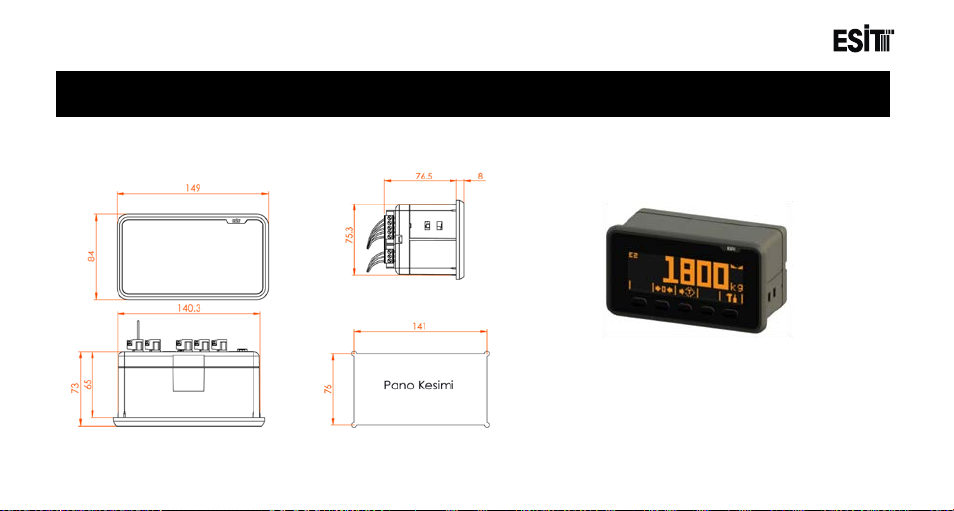
ECI Multi Functional Weighing Controller Operating Manual
Standard Model
Weight 360 g
3 Physical Dimensions
Page 17
Page 18

ECI Multi Functional Weighing Controller Operating Manual
Page 18
Page 19
ECI Multi Functional Weighing Controller Operating Manual
Model
ECI, E Series
Load Cell Input
+/- 2.50–160mV/V
A/D Speed (/second)
1600
Screen Resolution
6 digit (1/1.000.000)
Supply
12-24V DC
Display
LCD (101x33 pixel graphic, 4.5 inch)
Communication Terminal (Standard)
RS-232 (9600-115200bps)
Communication Remote Display (Standard)
For Remote Display (Opto-Coupler)
Communication Option Module (Optional)
RS-232-RS-485 / RS-422 (E-MDL-COM insulated)
Load Cell Feeding
10 VDC (280mA, maximum 10 load cells)
Operating Temperature
-10C / +50C
Protection Class
IP65 (Front Panel)
4 Specifications
4.1 Technical Specifications
(Standard: Supplied as standard hardware with the device)
(Optional: Inserted to the device as additional hardware)
Page 19
Page 20

ECI Multi Functional Weighing Controller Operating Manual
4.2 Use Properties
• Multi-language support
• 5 touch keys
• Plain use and setting thanks to the indexed menu system structure
• Internal batching and filling program
• Smart “plug and play” expan sion stru cture
• Gain setting adjustable according to the sensor output (capable of reading between ±20mV and ±1.6V)
• Connect ivity up to 1 0 load cells (350R)
• Software update by using USB
• Calibration without installation on the basis of the load cell data
• Facility to carry the calibration information between different devices.
• Easy test opportunity wi t h t he service menus (Serial Output, Digital inputs/outputs, LCD, memory, ADC input)
• 3 sectional weighing range (Wide Range , Multi Partition options)
• Automatic scale interval (e) and dot space adjustment
• gResolver, Smart numerical filter technology
• Storing current weighing device values and calibration info
• Monitoring the Load Cell info real time as mV/V from the service menu
• 16 recipe and double speed batching up to 8 silos
• Up to 24 optional digital output and up to 16 digital input
• Optional 2 x 0/10V – 4/20mA analogue output
• USB reporting
Page 20
Page 21

ECI Multi Functional Weighing Controller Operating Manual
Page 21
Page 22
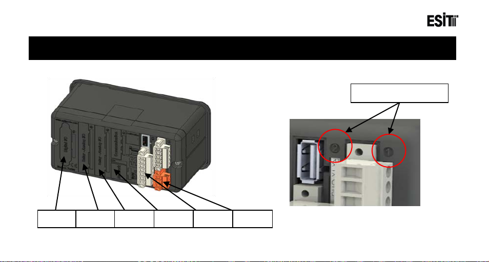
ECI Multi Functional Weighing Controller Operating Manual
Slot Numbers
Slot6
Slot5
Slot4
Slot3
Slot2
Slot1
5 Installation and Connections
The number of each slot is shown as follows on the back cover of the ECI device
Page 22
Page 23

ECI Multi Functional Weighing Controller Operating Manual
• Slot1: Used for the Terminal (Supply & Communication) Module. Following module(s) can be used;
E-ECI-PWR (Standard) module can be inserted.
• Slot2: Used for Weighing (Load Cell) Module. Following module(s) can be used;
E-ECI-LC (Standard) module can be inserted.
• Slot3: Used for optional Communication Module. Following module(s) can be used;
E-MDL-COM (Optional), RS232 + RS485/RS422 Module
E-MDL-PRF (Optional), Profibus Module
E-MDL-EIP (Optional), Ethernet IP Module
• Slot4: Used for Optional Input/Output modules. Following module(s) can be used;
E-MDL-RLY, 4in/4out Module (Optional)
E-MDL-DAC, 0-10V / 4-20mA Analogue +2in/1out Module (Opti onal )
• Slot5: Used for Optional Input/Output modules. Foll owing module(s) can be used;
E-MDL-RLY, 4in/4out Module (Optional)
E-MDL-DAC, 0-10V / 4-20mA Analogue +2in/1out Module (Opti onal )
• Slot6: Used for Expansion modules. Following module(s) can be used;
E-MDL-EXP, 8in/16out expansion module (Optional)
E-MDL-BCD, 20out/2In Optical Insulated BCD or Binary Output Module (Optional)
Page 23
Page 24
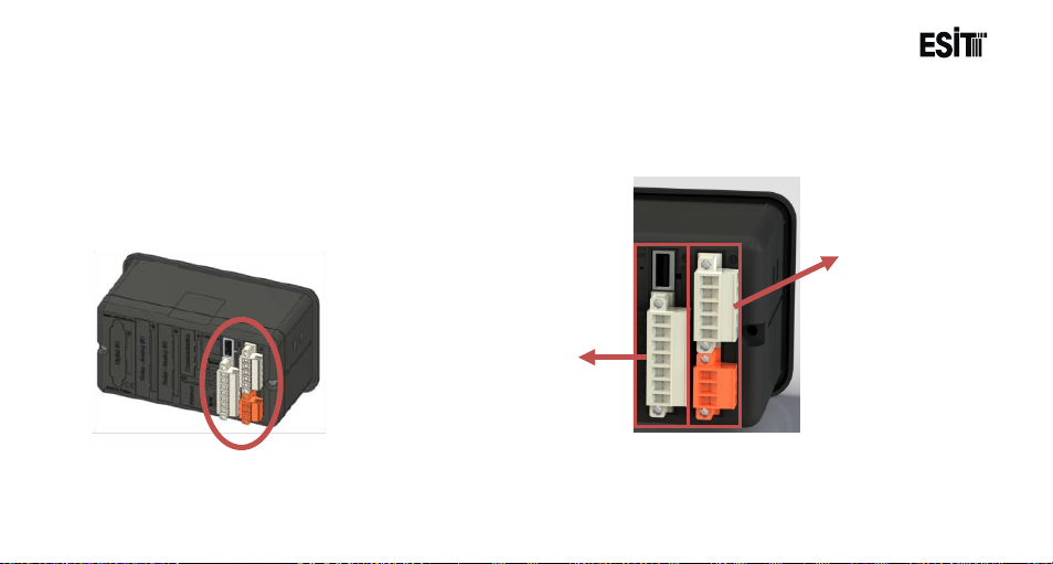
ECI Multi Functional Weighing Controller Operating Manual
Terminal Module
Weighing
Module
5.1 Standard Modules
Standard modules are the units that are given in the base mode with the ECI E series devices. Respective
modules and explanations are given below.
Page 24
Page 25
ECI Multi Functional Weighing Controller Operating Manual
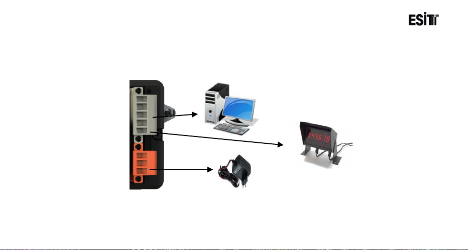
Remote Display Connection
RS232
Supply Connection
5.1.1 Slot1: Terminal (Supply and Communication Module)
Page 25
Page 26
ECI Multi Functional Weighing Controller Operating Manual
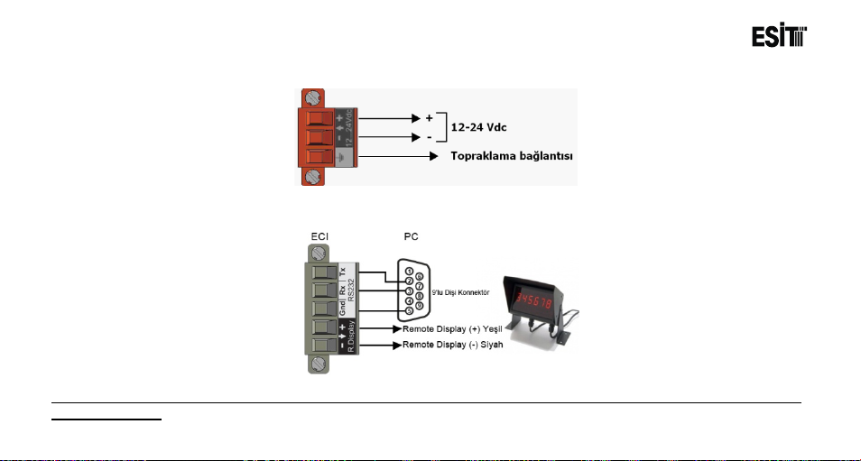
5.1.1.1 Supply Connection
5.1.1.2 Communication Connections
Note: When the “R.Display” output is used with Esit brand Remote displays, red and White cables of the Display must
be short circuited
Page 26
Page 27
ECI Multi Functional Weighing Controller Operating Manual
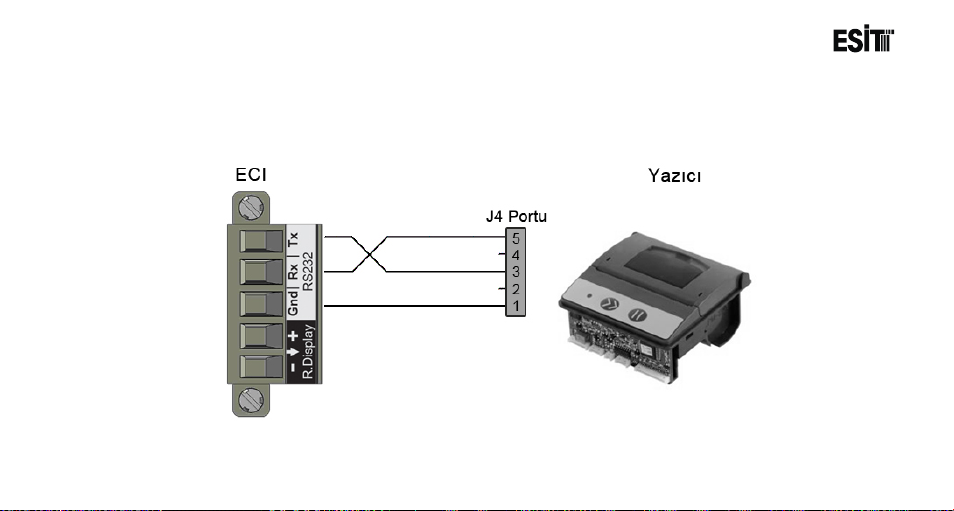
5.1.1.3 Printer Connection
Page 27
ECI, supports EPM203-MRS model printer. Printer connection must be as follows.
Page 28
ECI Multi Functional Weighing Controller Operating Manual
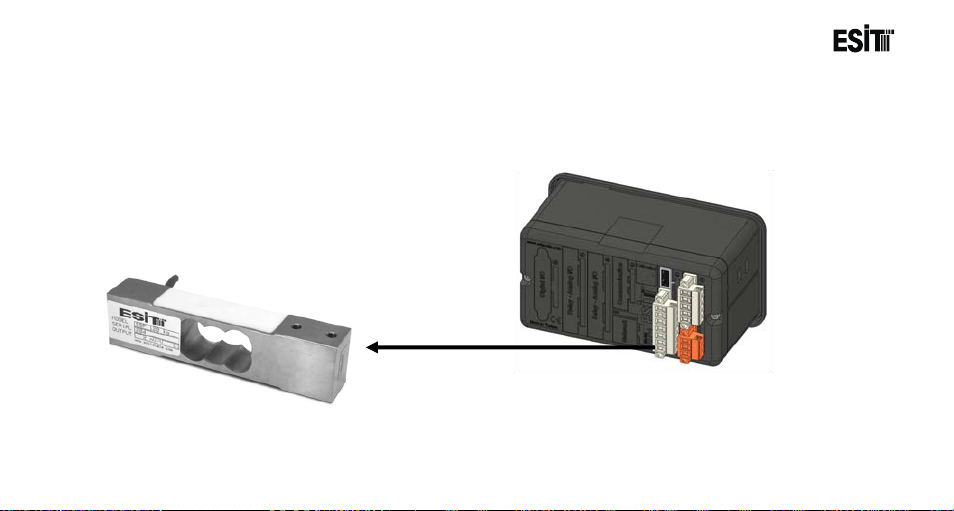
5.1.2 Slot2: Weighing (Load Cell) Module
5.1.2.1 Esit Load Cell Connection
Page 28
Page 29
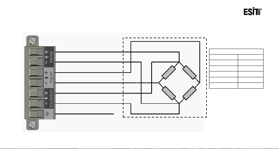
ECI Multi Functional Weighing Controller Operating Manual
Esit Colours
Sense +
Blue
Sense -
Orange
Out +
White
Out -
Red
Supply +
Green
Supply -
Black
Grounding
Sense +
Sense -
Out +
Out -
Supply +
Supply -
5.1.2.2 Six (6) Cable Load Cell Connection
Page 29
Page 30
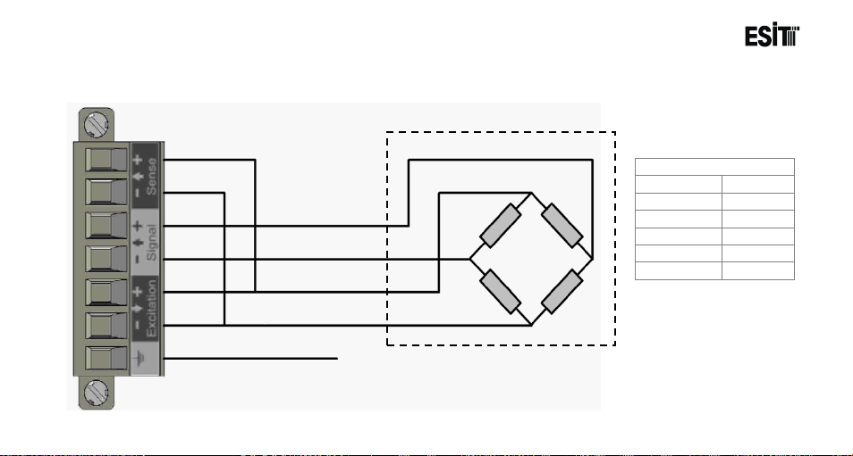
ECI Multi Functional Weighing Controller Operating Manual
Grounding
Out +
Out -
Supply +
Supply -
Esit Colours
Sense -
Green
Sense -
Black
Out +
White
Out -
Red
Supply +
Green
Supply -
Black
Sense-terminal is short
5.1.2.3 Four (4) Cable Load Cell Connection
circuit with Supply – terminal
and Sense+terminal is short
circuit with Supply + terminal
Page 30
Page 31

ECI Multi Functional Weighing Controller Operating Manual
Page 31
Page 32
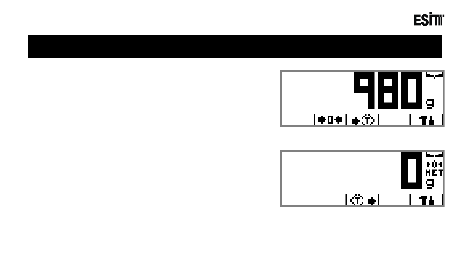
ECI Multi Functional Weighing Controller Operating Manual
6 Screenshots
6.1 Weighing Main Screen
Main screen shot will be as shown at side
The screen will be displayed as shown at side when the tare is
removed
Page 32
Page 33
ECI Multi Functional Weighing Controller Operating Manual
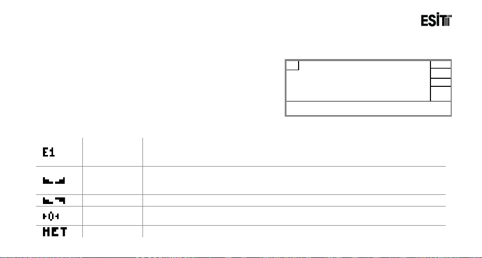
Indicates current weighing range. It is displayed when the measuring type is
and E3 represents the final zone.
Shows that the change in the weight value is within the stagnancy limits for a
(less than a one scale interval).
Mobility
Zero
Indicator
Net
Shows that the tare has been removed and the displayed value is the net value.
1. Weighing Indicator
2. Keys
3. Weighing Range
4. Mobility
5. Zero Indicator
6. Tare Status
7. Unit
3 1 2
4
5
6
7
6.1.1 Screen Layout
6.1.2 Symbols
Weighing
Range
Stagnancy
Page 33
selected as “Multi Partition” or “Multi Range”. E1: Lower Zone, E2: Upper Zone
certain period
Shows that the change in the weight value is out of the stagnancy limits.
Indicates that deviation from zero is less than 1/4e (resolution).
Page 34

ECI Multi Functional Weighing Controller Operating Manual
Page 34
Page 35
ECI Multi Functional Weighing Controller Operating Manual
6.1.3 Keys
Reset Key
Tare Key
Used for resetting the display.
Used for taking the weight on the load cell as tare.
Tare Clean Key
Menu Key
Page 35
Used for cancelling the tare value and showing the gross value.
Used for bringing the display menu where the device settings are made.
Page 36

ECI Multi Functional Weighing Controller Operating Manual
1. Menu Logo
3. Lock
4. Menu Names
5. Keys
1
2 3 4
5
6.2 Menu Screen
Menu screenshot is as shown at side.
6.2.1 Screen Layout
2. Menu No
Page 36
Page 37
ECI Multi Functional Weighing Controller Operating Manual
Shows that a parameter has to be changed in order to Access the
menu.
Shows that it is required to add or replace hardware in order to
Access the menu.
6.2.2 Symbols
Menu Logo
Respective menu logo.
Menu No
Software Lock
Hardware Lock
Page 37
Respective menu number.
Page 38
ECI Multi Functional Weighing Controller Operating Manual
6.2.3 Keys
Left Arrow Key
Up Arrow Key
Down Arrow Key
Right Arrow Key
Enter Key
Page 38
Used for shifting to an upper menu on the menu screen.
Used for browsing among the options on the menu screen.
Used for browsing among the options on the menu screen.
Used for shifting to an lower menu on the menu screen.
Used for entering to the menu next to the menu number.
Page 39
ECI Multi Functional Weighing Controller Operating Manual
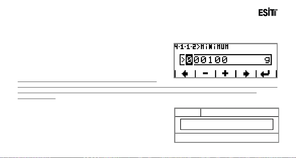
1. Menu No
2. Menu Title
3. Value to be Adjusted
4. Keys
2 3 4
1
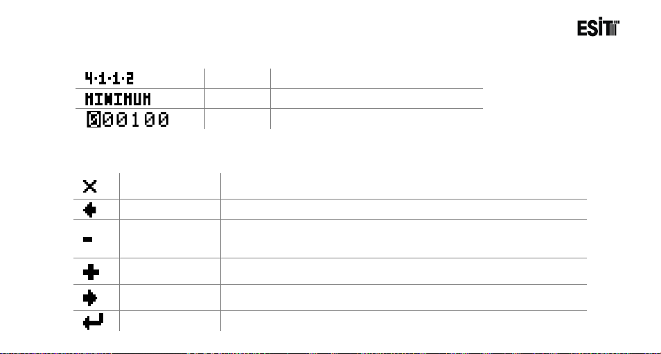
6.3 Change Parameter Screen (Numeric or Alpha-Numeric Entry Type)
The change parameter screen will be displayed as shown
at side:
Note: The values entred in the screen must the multiplies of the
“Resolution” parameter. For example if the ”Resolution” is selected as 5 and the value entered in this screen is 101, an
information message appears and the number is automatically rounded to 100 and returned to the parameter
changing screen.
6.3.1 Screen Layout
Page 39
Page 40
ECI Multi Functional Weighing Controller Operating Manual
Used for returning to the menu screen from the parameter settings
screen
Used for decreasing the digit on which the cursor is located in the
screen.
Used for increasing the digit on which the cursor is located in the areas
where numerical value is entered in the parameter setting screen.
Right Arrow
Key
6.3.2 Symbols
Menu No
Title
Option
Respective menu number.
Name of the current menu
Value to be adjusted
6.3.3 Keys
Exit Key.
Left Arrow Key
Minus Key
Plus Key
Page 40
Confirm Key
Used for shifting the cursor to the left.
areas where numerical value is entered in the parameter setting
Used for shifting the cursor to the right.
Used for confirming the selected screen.
Page 41

ECI Multi Functional Weighing Controller Operating Manual
Page 41
Page 42

ECI Multi Functional Weighing Controller Operating Manual
1. Menu No
2. Menu Title
3. Option No
4. Option
5. Arrow
6. Keys
2 3 5 6 4
1
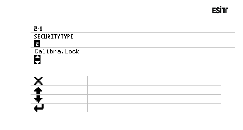
6.4 Change Parameter Screen (Selective Type)
The selective type change parameter screen will be
displayed as shown at side:
6.4.1 Screen Layout
Page 42
Page 43
ECI Multi Functional Weighing Controller Operating Manual
Shows if there is any option above or below the
selection list
Used for returning to the menu screen from the parameter settings
screen
6.4.2 Symbols
Menu No
Menu Title
Option No
Option
Arrow
Respective menu number.
Name of the respective parameter.
Number of the parameter option.
Explanation of the respective parameter option.
6.4.3 Keys
Exit Key.
Up Arrow Key
Down Arrow Key
Enter Key
Page 43
Used for browsing among the options in the selection list.
Used for browsing among the options in the selection list.
Used for conforming the value selected.
Page 44
ECI Multi Functional Weighing Controller Operating Manual
1. Menu No
2. Menu Title
3. Sub-Menu Title
4. Sub-Menu No
5. Sub-Menu
Number
6. Option No
7. Option
8. Arrow
9. Keys
1
2 3 4
5
6 7 8
9
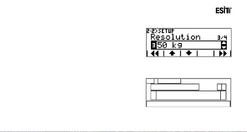
6.5 Ordered Menu Screen
Ordered menu is made for providing convenience in the menus
with more than one sub-menu. For example, there are Unit,
Capacity, Resolution and Measuring Type sub-menus in the
Settings menu under the Weighing menu. When you enter this
menu, you can change every parameter related to the weighing
setting subsequently. The ordered menu screenshot will be as
sown at side
6.5.1 Screen Layout
Page 44
Page 45
ECI Multi Functional Weighing Controller Operating Manual
Number of SubMenu
Shows if there is any option above or below
the selection list
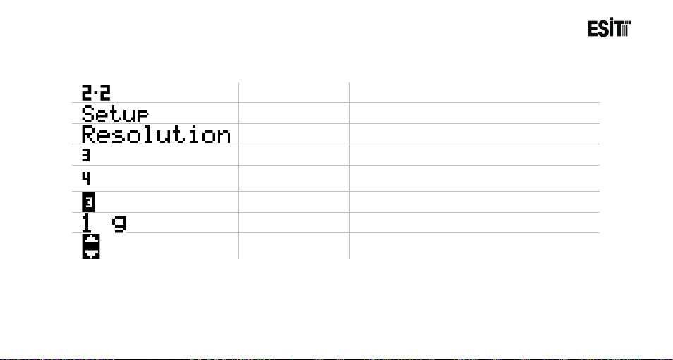
6.5.2 Symbols
Menu No
Menu Title
Sub-Menu Title
Sub-Menu No
Option No
Option
Arrow
Page 45
Respective menu number.
Name of the current menu.
Name of the current sub-menu.
Sub-Menu number.
Number of Sub-Menus of the respective menu
Option number
Respective option
Page 46

ECI Multi Functional Weighing Controller Operating Manual
Used for returning to the menu screen from the ordered menu
screen
6.5.3 Keys
Return Key
Page 46
Up Arrow Key
Down Arrow Key
Forward Key
Exit Key.
Used for returning to the previous menu in the ordered menu.
Used for browsing among the options in the selection list.
Used for browsing among the options in the selection list.
Used for forwarding to the next menu in the ordered menu.
Page 47
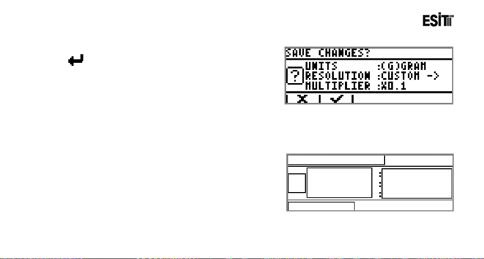
ECI Multi Functional Weighing Controller Operating Manual
1. Screen Title
2. Confirmati on Logo
3. Parameters Changed
4. New Parameter Values
5. Keys
1
2
3
4
5
6.6 Confirmation Screen
When key is pushed after entering to menu and changing
any parameter, the confirmation screen as shown at side will
appear before saving the new parameter.
6.6.1 Screen Layout
Page 47
Page 48
ECI Multi Functional Weighing Controller Operating Manual
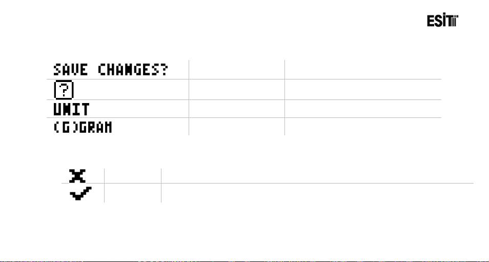
Confirmation Screen
Title
Confirmation Screen
Logo
Confirm
Key
6.6.2 Symbols
Respective menu title.
Parameters Changed
Parameter Value
Respective menu logo.
Name of the parameter changed
New value of the parameter changed.
6.6.3 Keys
Cancel Key
Page 48
Used for returning to the previous menu without saving the parameters changed.
Used for saving the parameters changed.
Page 49

ECI Multi Functional Weighing Controller Operating Manual
1. Message Screen Title
2. Message No
3. Message Logo
4. Message
1
2
3
4
6.7 Message Screen
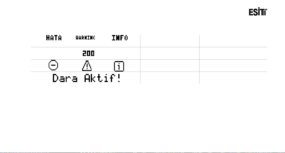
The message screen shown at side will display when it is
necessary to inform the user.There are 3 types of message
These are information, warning and error messages.
6.7.1 Screen Layout
Page 49
Page 50
ECI Multi Functional Weighing Controller Operating Manual
Respective message
number.
The logo related to the
message type.
6.7.2 Symbols
Message Screen Title
Indicates the message type
Page 50
Message No
Message Screen Logo
Message
The message content
Page 51

ECI Multi Functional Weighing Controller Operating Manual
Page 51
Page 52

ECI Multi Functional Weighing Controller Operating Manual
7 Using the Device
The device is turned on by supplying energy after making the Supply and Load Cell connections. Start-up logo and
version number will be displayed on ECI LCD screen during the start-up. Then the functional test will be performed
and the Optional card inserted will be recognized and tested. Lastly, the main screen will be displayed and the
measuring starts.
Page 52
Page 53

ECI Multi Functional Weighing Controller Operating Manual
7.1 Program Selection
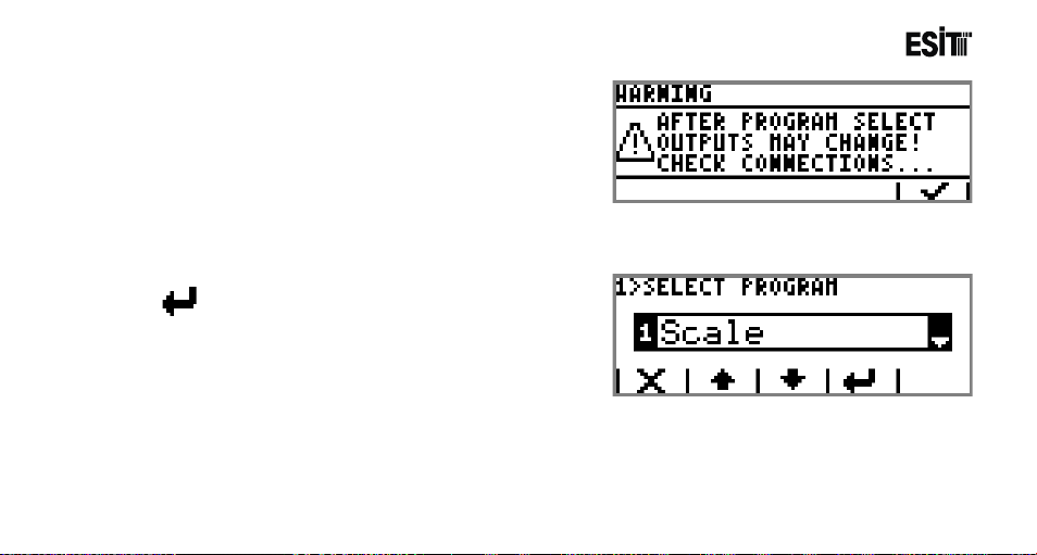
ECI, supports more than one operating screens (programs) (such as "Weighing," Batching", "Filling" etc).
Operating screen selection is made when the first energy is given to the device. After gi ving the first energy, when
the following screenshot appears, the 1. and 3. keys from the left are pushed together
7.1.1 Start-up Screen
The desired program is selected from "Select Program"
menu appeared. Related screenshot is shown below.
Page 53
Page 54
ECI Multi Functional Weighing Controller Operating Manual
The status of the outputs may change when the program is
changed. Thus, the respective warning message is
displayed before the program selection screen.
7.1.2 Program Selection Screen
After selecting the desired program, selection is confirmed
with key and it is shifted to the desired operating
program.
Page 54
Page 55

ECI Multi Functional Weighing Controller Operating Manual
1. Terminal
2. Weighing
3. Optional Communication Menu
7.2 Menu List
Menu List is as follows:
1.1. Language
Selection
Page 55
1.2. Date
1.3. Time
1.4. Communication
1.5. USB Recording
1.6. Keys
1.7. Service
2.1. Security Type
2.2. Settings
2.3. Filter
2.4. Zero/Tare
2.5. Calibration
2.6. Service
4. Optional In/Out Menu
5. Optional In/Out Menu
6. Optional Expansion Menu
Page 56
ECI Multi Functional Weighing Controller Operating Manual
7.3 Using the Menu
7.3.1 Terminal Menu
The menus related to the Terminal module inserted to slot 1
of the device are displayed under this menu.
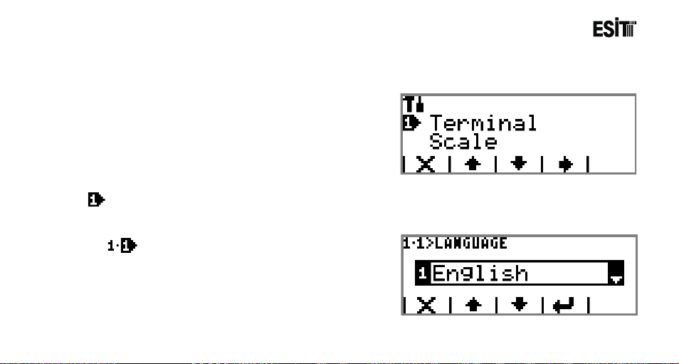
Terminal
It is the main menu that contains the device settings and the settings related to Slot1.
Language Selection
The language selection for the device. The options
are;
1) Turkish
2) English
Page 56
Page 57
ECI Multi Functional Weighing Controller Operating Manual
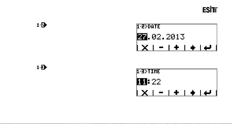
Date
Date settings are made. The date data can be changed
in dd.mm.yyyy format.
Time
Time settings are made. The time data can be
changed in hh.mm format.
Page 57
Page 58
ECI Multi Functional Weighing Controller Operating Manual
Character
‘ ‘
‘ ‘
‘ ‘
‘ ‘
‘ 2‘
‘ 1‘
‘ 4‘
‘ 8‘
‘.’
‘ 0‘
CR
Ascii
32
32
32
32
50
49
52
56
46
48
13
Hex
20
20
20
20
32
31
34
38
2E
30
0D
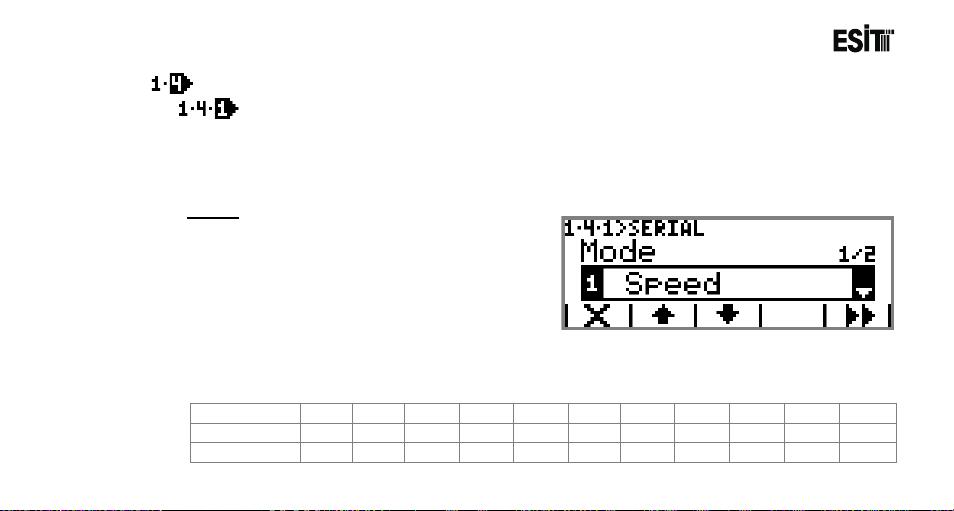
Communication
Serial Out
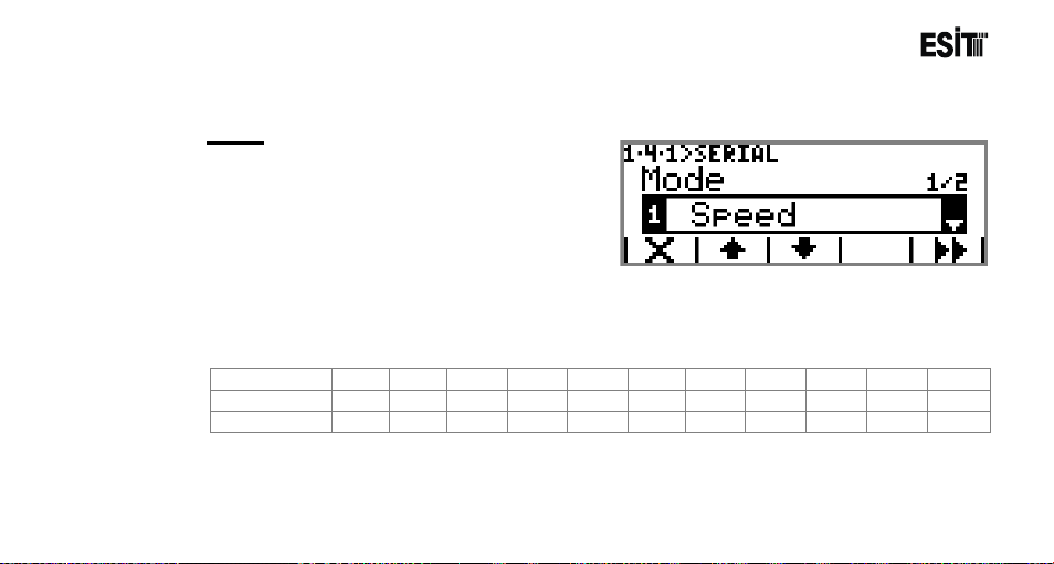
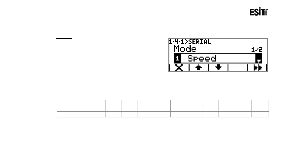
Contains the terminal serial out settings. This menu is an ordered type menu. Sub-menus are Mode
and Period. It functions differently in Indication, Batching and Filling programs. Explanation i s m ade
below for each program
Indicat ion Progr am
Mode
It is the communication type selection. The
options are;
1) Speed: Net weight information is sent
continuously.
(Baudrate is 115200bps)
For example;
The screen value of "2148.0kg" is sent as follows.
Page 58
Page 59

ECI Multi Functional Weighing Controller Operating Manual
Page 59
Page 60
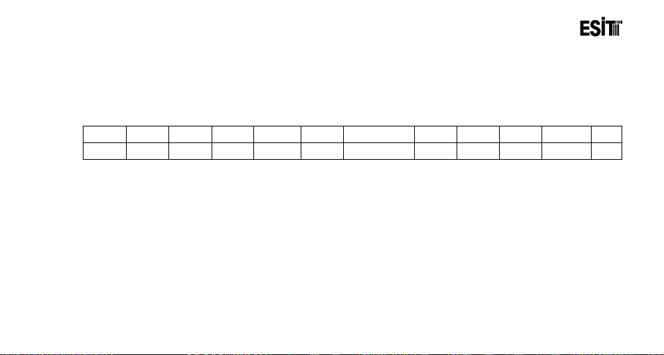
ECI Multi Functional Weighing Controller Operating Manual
Net
TAB
Tare
TAB
Gross
TAB
Date
TAB
Time
TAB
Status
CR
169.2
Chr 9
128.5
Chr 9
297.7
Chr 9
12/02/2013
Chr 9
09:52
Chr 9
S
CR
2) Accuracy: Net weight information is sent continuously. (Baudrate is 9600bps)The form at of the
data string sent is same as the Speed mode
3) Detail: The weight information is sent in detail.(Baudrate is 9600bps).The format of the data
string sent is as follows.
Status
E:Error
Z:Absolute Zero
S:Stagnancy
- :This symbol appears when non of the abovementioned conditions occur.
Page 60
Page 61

ECI Multi Functional Weighing Controller Operating Manual
4) Stability: Net weight information is sent 10 times when the stability is observed.(Baudrate is
9600 bps.) The format of the data string sent is same as the Speed mode.
5) Command: Functions as a query from a remote computer or similar device (Baudrate is
9600bps)
Not case sensitive
Command List:
'R' : Resets the device (Reset).
'Z' : Functions as reset key.
'T' : Functions as tare key.
'W' : Recovers the existing measurement results
'A' : Returns ADC internal count value.
'V' : Returns device version number.
'GIn' : Rotates the card type numeric entries of the modules inserted in slot 4 and 5. The card
types and inputs in slot 4 and and 5 are rotated with GI0 and GI1 commands respectively.
'GOn' : Recovers the card type numeric entries of the modules inserted in slot 4 and 5.
Yuvadaki modüllerin sayısal çıkışlarını geri döndürür.GO0 komutuyla 4.
Are rotated with GI0 and GO1 commands Yuvadaki çıkışlar döndürülür.
Page 61
Page 62

ECI Multi Functional Weighing Controller Operating Manual
1 0 0 1 Input4
Input3
Input2
Input1
0 0 1
1
Exit4
Exit3
Exit2
Exit1
For example;
Command: GI0
Response: 1001->LSB(Input1)
0: No Input:
1: Input exists
For example;
Command: GO0
Response: 3
The binary number system equivalent of the response received: 0011
1: Exit
0: No Exit
Page 62
Page 63

ECI Multi Functional Weighing Controller Operating Manual
6) Printer: It is the printer connection option. This option is locked as it is not active under the
indication program.
Period
Selection for RS232 serial out sending frequency.
The options are;
1) 6/Min
2) 1/Sec
3) 10/Sec
4) 100/Sec
5) 400/Sec
6) 800/Sec
Not: Period menu is not shown when "Command" or "Stability" modes are selected.
When "Speed" Mode is selected, Period can be selected as 100-800/Sec
When "Accuracy" mode is selected, Period can be selected as 6/Min-10/Sec
When "Detail" mode is selected, Period can be selected as 6/Min-10/Sec
Page 63
Page 64
ECI Multi Functional Weighing Controller Operating Manual
Character
‘ ‘
‘ ‘
‘ ‘
‘ ‘
‘ 2‘
‘ 1‘
‘ 4‘
‘ 8‘
‘.’
‘ 0‘
CR
Ascii
32
32
32
32
50
49
52
56
46
48
13
Hex
20
20
20
20
32
31
34
38
2E
30
0D
Batching Program
Mode
It is the communication type selection. The
options are;
1) Speed: Net weight information is sent
continuously during the batching operation.
(Baudrate is 115200bps)
For example;
The screen value of "2148.0kg" is sent as follows.
Page 64
Page 65
ECI Multi Functional Weighing Controller Operating Manual
Silo
Name
Meter
Total number of Batching Resets when the recipe is changed or the device is
restarted.
Silo No
Number of the last silo from which good was taken
Silo Weight
Quantity of the goods taken from the last silo
Total
Last batching amount
Date
Last batching date
Time
Last batching time
2) Accuracy: Net weight information is sent continuously during the batching operation. (Baudrat e
is 9600bps)The format of the data string sent is same as the Speed mode
3) Detail: The information is sent in detail after the batching operation is over. (Baudrate is
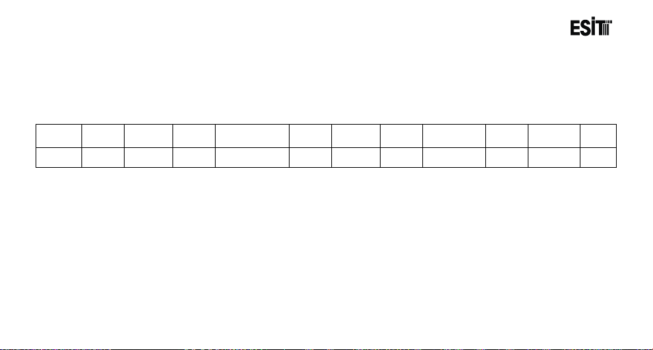
9600bps).The format of the data string sent is as follows.
Meter TAB
2 Chr 9 Silo3 Chr 9 300 Chr 9 1200 Chr 9 16.04.2013 Chr 9 08:50:19 CR
Page 65
TAB Silo Weight TAB Total TAB Date TAB Time CR
Page 66
ECI Multi Functional Weighing Controller Operating Manual
4) Stability: The total batching weight is sent after the batching is over.(Baudrate is 9600 bps.) The
format of the data string sent is same as the Speed mode.
Command: This mode is not active in batching mode.
5) Printer: It is the printer connection option.
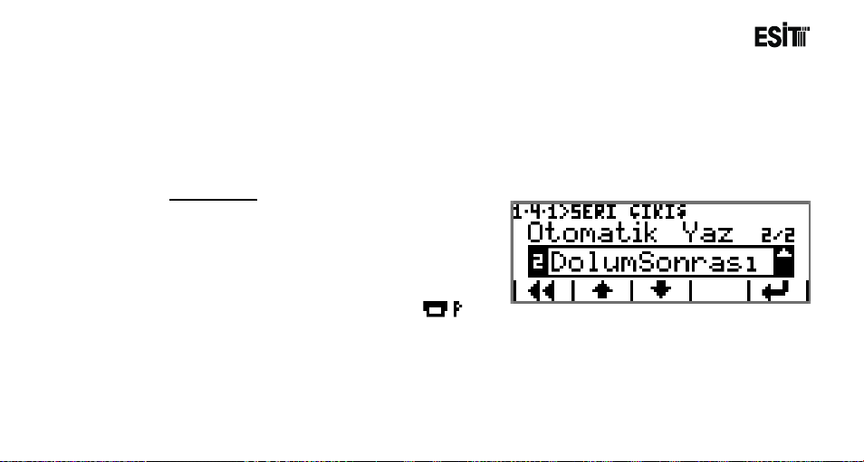
Auto Print
It is the printer operation mode selection. The
options are;
1) Manuel: Printing is only possible from the
"Report" screen.
2) After Filling: Printing operation is made
according to the settings in "Printer Settings
Menu" after the batching is completed. key
is also used for manual printing at the report screen.
Page 66
Page 67
ECI Multi Functional Weighing Controller Operating Manual
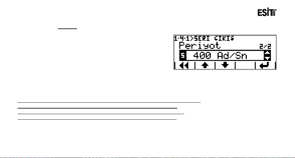
Period
Selection for RS232 serial out sending frequency.
The options are;
7) 6/Min
8) 1/Sec
9) 10/Sec
10) 100/Sec
11) 400/Sec
12) 800/Sec
Not: Period menu is not shown when "Command" or "Stability" modes are selected.
When "Speed" Mode is selected, Period can be selected as 100-800/Sec
When "Accuracy" mode is selected, Period can be selected as 6/Min-10/Sec
When "Detail" mode is selected, Period can be selected as 6/Min-10/Sec
Page 67
Page 68
ECI Multi Functional Weighing Controller Operating Manual
Character
‘ ‘
‘ ‘
‘ ‘
‘ ‘
‘ 2‘
‘ 1‘
‘ 4‘
‘ 8‘
‘.’
‘ 0‘
CR
Ascii
32
32
32
32
50
49
52
56
46
48
13
Hex
20
20
20
20
32
31
34
38
2E
30
0D
Filling Program
Mode
It is the communication type selection. The
options are;
1) Speed: The filling weight is sent continuously
during the filling.
(Baudrate is 115200bps)
For example;
The screen value of "2148.0kg" is sent as follows.
Page 68
Page 69
ECI Multi Functional Weighing Controller Operating Manual
Filling
Quantity
Chr
9
Chr
9
Chr
9
Chr
9
Chr
9
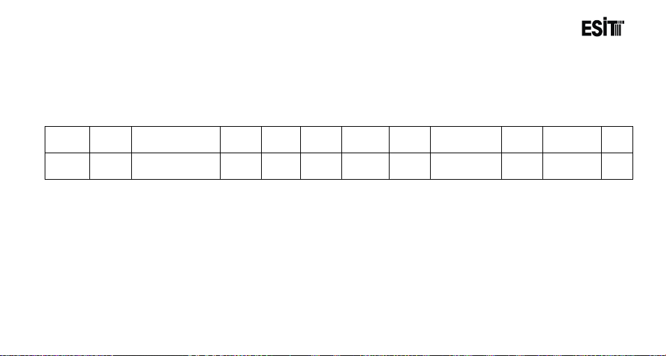
Meter
Total number of filling. Resets when the product is changed or the device is restarted.
Filling
Quantity
Tare
The weight value on the weighing platform when the filling started
Gross
Sum of the filling quantity and the Tare value
Date
Time
Time of the Last Filling
2) Accuracy: The filling weight is sent continuously during the filling.
(Baudrate is 9600bps)The format of the data string sent is same as the Speed mode
3) Detail: The information is sent in detail after the filling operation is over. (Baudrate is
9600bps).The format of the data string sent is as follows.
Meter TAB
TAB Tare TAB Gross TAB Date TAB Time CR
3
1000
100
1100
16.04.2013
09:25:50 CR
Value of the Last Filling
Date of the Last Filling
Page 69
Page 70
ECI Multi Functional Weighing Controller Operating Manual
4) Stability: The final filling weight is sent after the filling is over.(Baudrate is 9600 bps.) The format
of the data string sent is same as the Speed mode.
5) Command: This mode will be shown as locked as it is not active in filling program.
6) Printer: It is the printer connection option.
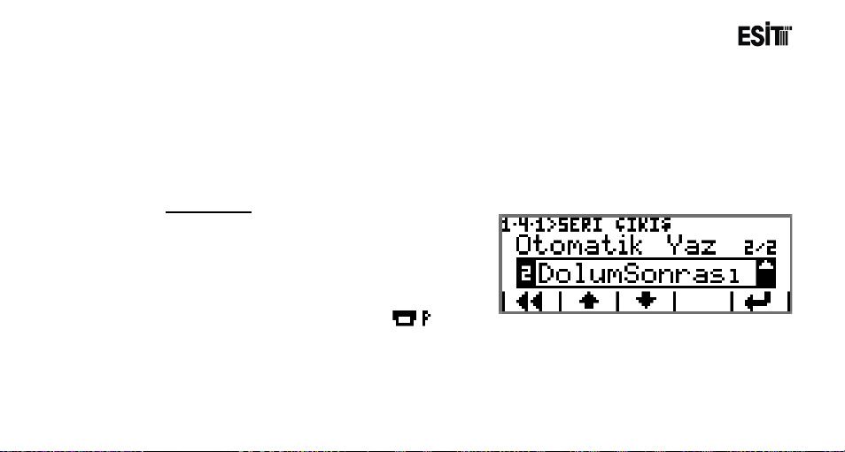
Auto Print
It is the printer operation mode selection. The
options are;
1) Manuel: Printing is only possible from the
"Report" screen.
2) After Filling: Printing operation is made
according to the settings in "Printer Settings
Menu" after the filling is completed. Key is
also used for manual printing at the report screen.
Page 70
Page 71
ECI Multi Functional Weighing Controller Operating Manual
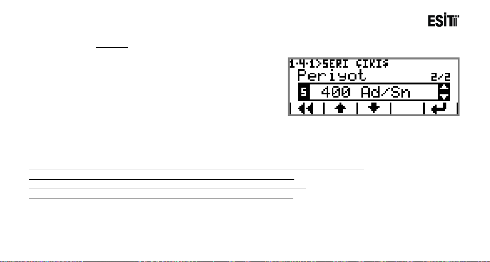
Period
Selection for RS232 serial out sending frequency.
The options are;
1) 6/Min
2) 1/Sec
3) 10/Sec
4) 100/Sec
5) 400/Sec
6) 800/Sec
Not: Period menu is not shown when "Command" , "Stability" or "Detail modes are selected.
When "Speed" Mode is selected, Period can be selected as 100-800/Sec
When "Accuracy" mode is selected, Period can be selected as 6/Min-10/Sec
When "Detail" mode is selected, Period can be selected as 6/Min-10/Sec
Page 71
Page 72
ECI Multi Functional Weighing Controller Operating Manual
Remote Display(In Indication and Filling Programs)
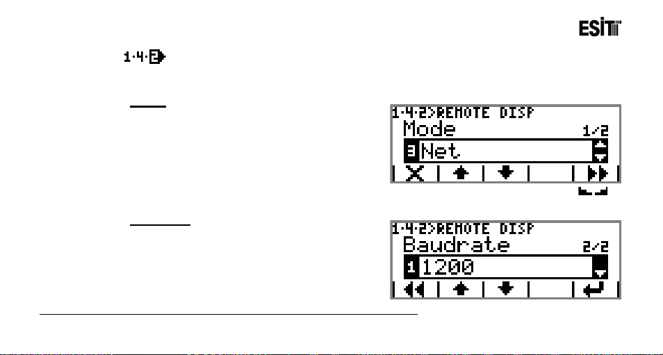
It is the section that contains the remote display out (opto-coupler) settings. This menu is an ordered
type menu. Sub-menus are Mode and Baudrate.
Mode
The options are;
1) Inactive: No data transfer can be made to the
remote display.
2) Gross: Gross value is sent to the remote
display.
3) Net: Net value is sent to the remote display.
4) Stable-Net: The "Net" value is sent to the remote display when the Stagnancy indicator( ) is
active.
Baudrate
It is the selection for remote display
communication speed. The options are;
1) 1200
2) 2400
3) 4800
Not: The Baudrate menu is not displayed when "Inactivate" mode is selected
Page 72
4) 9600
Page 73
ECI Multi Functional Weighing Controller Operating Manual
Remote Display(In Batching Program)
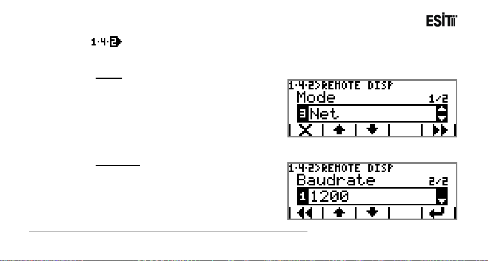
It is the section that contains the remote display out (opto-coupler) settings. This menu is an ordered
type menu. Sub-menus are Mode and Baudrate.
Mode
The options are;
1) Inactive: No data transfer can be made to the
remote display.
2) Silo: The value of the sil o filled is sent to the
remote display.
3) Total: Total batching val ue is sent to the
remote display.
4) Weight: Gross weight value is sent to the remote display.
Baudrate
It is the selection for remote display
communication speed. The options are;
1) 1200
2) 2400
3) 4800
4) 9600
Not: The Baudrate menu is not displayed when "Inactivate" mode is selected
Page 73
Page 74
ECI Multi Functional Weighing Controller Operating Manual
USB Recording
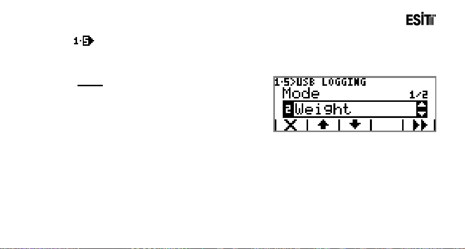
It is the menu where the recording settings are made. This menu is an ordered type menu. Sub-menus
are Mode and Period. It is active under filling and indication programs.
Mode
It is the recording type selection. The options are;
1) Inactive: No recording is made.
2) Weight: Net weight value is recorded.
3) Detail: Weight data is recorded in detail.
Page 74
Page 75
ECI Multi Functional Weighing Controller Operating Manual
Net
CR
Net
TAB
Tare
TAB
Gross
TAB
Date
TAB
Time
TAB
Status
CR
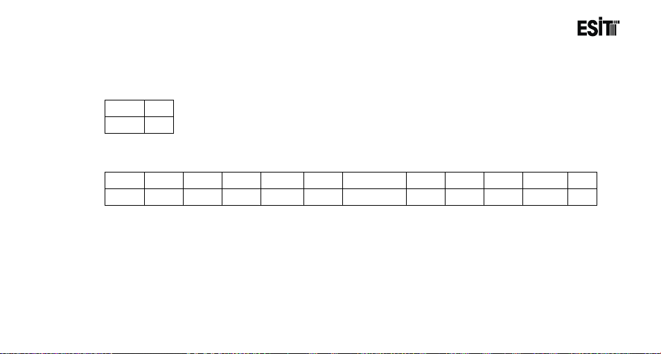
The format of the data recorded in indication program is as follows.
USB recording mode "Weight"
169.2 CR
USB recording mode "Detail"
169.2 Chr 9 128.5 Chr 9 297.7 Chr 9 12/02/2013 Chr 9 09:52 Chr 9 S CR
Status
E:Error
Z:Absolute Zero
S:Stagnancy
- :This symbol appears when non of the abovementioned conditions occur.
The name of the saved file is as "YearMonthDayeMode" format. For example; 20130412D
Page 75
Page 76
ECI Multi Functional Weighing Controller Operating Manual
Net
CR
Meter
TAB
Date
TAB
Time
TAB
Total
TAB
Silo1
TAB
Silo2
CR
Meter
It is the batching number. Resets when the recipe is changed or the device is
turned on.
Date
Date data in Day.Month.Year format.
Time
Time data in Hour.Minute.Second format.
Total
The amount of goods batched
Silo1
Quantity of the goods taken from Silo1
Silo2
Quantity of the goods taken from Silo2
The format of the data recorded in batching program is as follows.
USB recording mode "Weight"
100 CR
USB recording mode "Detail"
1 Chr 9 12/02/2013 Chr 9 09:52 Chr 9 100 Chr 9 75 Chr 9 25 CR
Page 76
Page 77

ECI Multi Functional Weighing Controller Operating Manual
The name of the saved file is as "YearMonthDayeMode"_RecipeName format. For example;
12042013W_RECETE1
Page 77
Page 78
ECI Multi Functional Weighing Controller Operating Manual
Net
CR
Meter
TAB
Total
TAB
Tare
TAB
Gross
TAB
Date
TAB
Time
CR
Meter
It is the batching number. Resets when the recipe is changed or the device is
turned on.
Total
The amount of goods batched
Tare
It is the tare value received at the beginning of the filling when the Automatic
Tare "On" is selected
Gross
Sum of the total and tare value
Date
Date data in Day.Month.Year format.
Time
Time data in Hour.Minute.Second format.
The format of the data recorded in filling program is as follows.
USB recording mode "Weight"
1000 CR
USB recording mode "Detail"
1 Chr 9 1000 Chr 9 100 Chr 9 1100 Chr 9 12/02/2013 Chr 9 09:52:23 CR
Page 78
Page 79

ECI Multi Functional Weighing Controller Operating Manual
The name of the saved file is as "YearMonthDayeMode"_ProductName format. For example;
12042013D_Nohut
Page 79
Page 80
ECI Multi Functional Weighing Controller Operating Manual
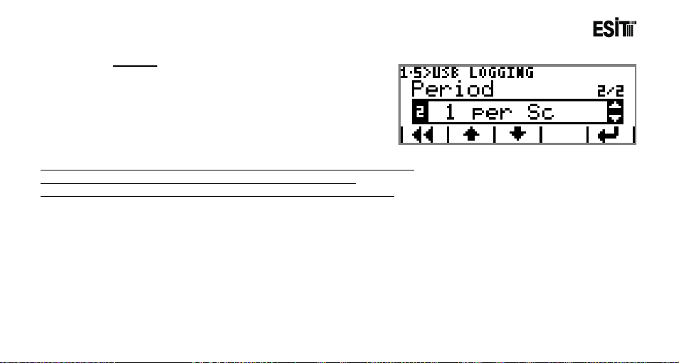
Period
It is the selection for USB Recording frequency. The
options are;
1) 10/Sec
2) 1/Sec
3) 1/Min
4) 4/Hour
Not: The Period menu is not displayed when "Inactivate" mode is selected
Period menu is not displayed in Batching and Filling programs.
When "Detail" mode is selected, Period can not be selected as 10/Sec
Page 80
Page 81
ECI Multi Functional Weighing Controller Operating Manual
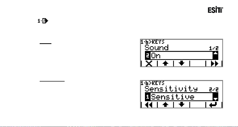
Keys
It is the menu where the key settings are made. This menu is an ordered type menu. Sub-menus are
"Tone" and "Sensitivity".
Tone
It is the key tone selection. The options are;
1) On
2) Off
Sensitivity
It is the selection for the perception setting of the
keys The options are;
1) Sensitive: It is the option where the perception is
the highest. Suitable for using with gloves.
2) Standard: It is the state of normal operation.
3) Stable: It is the option where the perception is the
lowest.
Page 81
Page 82
ECI Multi Functional Weighing Controller Operating Manual
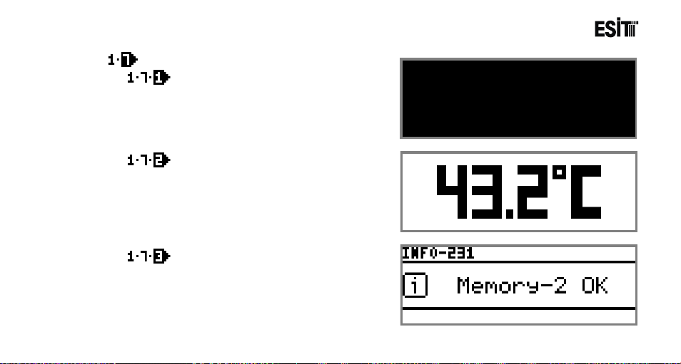
Service
LCDPixelTest
It is the screen test menu in LCD. Pixel and rear
light control is made.
CPU Temperature
Inside temperature of the device is displayed for 3
seconds.
Memory Test
It is used for understanding whether the memory is
functional or not.
Page 82
Page 83
ECI Multi Functional Weighing Controller Operating Manual
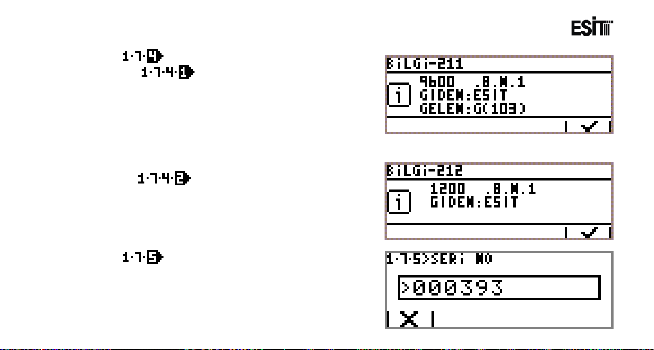
CommunicationTest
Terminal
It is used for understanding whether the
communication port is functional or not. The
data received from the serial port is displayed
at the receiving section. "ESIT" wording is sent
to the serial port at the same time.
It is used for understanding whether the
communication port is functional or not. "ESIT"
wording is sent to the remote display.
Used for displaying the device serial number.
Page 83
Remote Display
Serial No
Page 84
ECI Multi Functional Weighing Controller Operating Manual
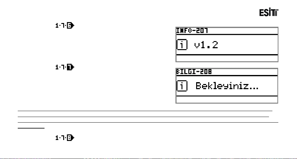
Version No
Used for displaying the device version number.
FactorySettings
Used for returning the device parameters to the
Factory settings.
Note: The device can also be returned to the factory settings by pressing to the calibration key for 10 seconds while
the device is at the main screen. The warning screen appearing later on will display that the factory settings will be
returned and sound warning is given. The factory settings will be returned when it is pressed for an additional period of
25 seconds.
Page 84
Restart
Used for restarting the device.
Page 85
ECI Multi Functional Weighing Controller Operating Manual
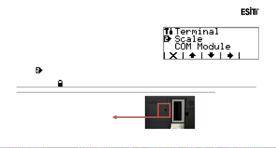
Calibration Key
7.3.2 Weighing Menu
The menus related to the weighing module inserted to slot 2
of the device are displayed under this menu.
Weighing
It is the menu that contains weighing device (Slot2-Load Cell Module) parameters.
Note: If the symbol presents in any of the sub-menus of the Weighing menu, then the menu cannot be accessible.
In such case, it is necessary to press the calibration case to activate in order to access the menu.
Page 85
Page 86
ECI Multi Functional Weighing Controller Operating Manual
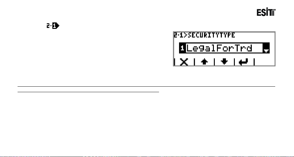
Security Type
Contains the weighing device security settings. The
options are;
1) Commercial Use:Weighing parameters and
calibration cannot be changed. (Locked)
2) CalibrationLock: Weighing parameters can be
changed but the calibration cannot be changed.
(Locked)
3) Unlocked: Weighing parameters and calibration can be changed.
Note: If the security type is selected as "Commercial Use" or "Calibration Lock", primarily the calibration key should be
pressed and the lock should be removed for making any change.
Page 86
Page 87
ECI Multi Functional Weighing Controller Operating Manual
Settings
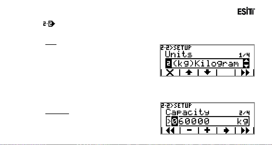
This menu is an ordered type menu where the weighing parameters are set forth. The sub-menus are
"Unit", "Capacity", "Resolution" and "Measuring Type".
Unit
Determines the unit of the weighing device . The
options are;
1) (g)Gram
2) (kg)Kilogram
3) (t)Ton
4) (N)Newton
5) (lb)Libre
6) (lt)Litre
7) (mV/V) Input
8) (m3)Cubic meter
9) None
Capacity
It is the capacity value of the device. The capacity of
the load cell must not be exceeded.
Page 87
Page 88
ECI Multi Functional Weighing Controller Operating Manual
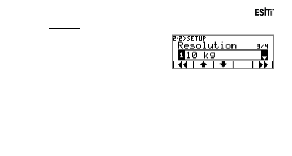
Resolution
It is the scale interval (e) selection.
e: It is the smallest screen change quantity.
Scale Interval
Scale Interval is automatically calculated as the
multiplies of 1, 2 and 5 depending on the capacity
parameter and presented as a selection. The options
are;
1) Capacity / 6000: The value calculated as 1/6000
as standard.
2) Capacity / 3000: The value calculated as 1/3000 as standard.
3) Capacity / 1500: The value calculated as 1/1500 as standard.
4) Custom: This option is selected if it is desired to select a resolution other than these first three
options.
Page 88
Page 89
ECI Multi Functional Weighing Controller Operating Manual
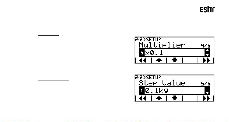
When the custom resolution is selected Multiple and Scale Interval menus appear and the product of
the values selected in these menus are determined as the walking step.
Multiples
The options are;
1) 1000
2) 100
3) 10
4) 1
5) 0.1
6) 0.01
7) 0.001
Scale Interval
The options are;
1) 1
2) 2
3) 5
Page 89
Page 90
ECI Multi Functional Weighing Controller Operating Manual
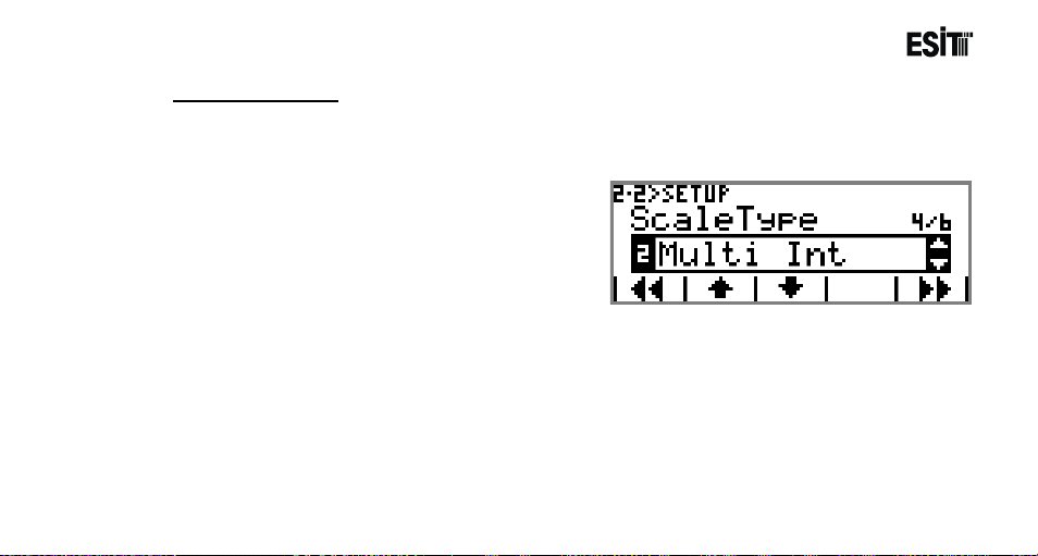
Measuring Type
Determines the operation of the weighing device. In weighing devices;
“e”: is referred as the scale interval It is the difference between two subsequent indications.
There may be a signle "e" division as well as more than one partitions. The options related to this
parameter are;
1) Single Partiti on
2) Multi Interval
3) Multi Partition
Page 90
Page 91
ECI Multi Functional Weighing Controller Operating Manual
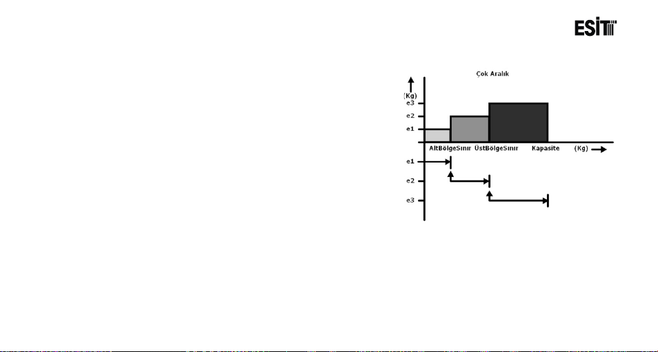
Single Partiti o n: The weighing device with a single scale interval and capacity.
Multi Interval: In this operation there are 3 different scale intervals and
capacities. There is a different scale interval in each capacity range;
Weight < LowerZoneLimit + 9e1 e1 (the first zone scale interval)
LowerZoneLimit + 9e1 < Weight < UpperZoneLimit + 9e2 e2 = 2*e1
(the second zone scale interval)
UpperZoneLimit + 9e1 < Weight < Capacity + 9e3 e3 = 2*e2 (the
third zone scale interval)
"e1" scale interval is determined with Resolution paramet er. e2 and e3
are determined automatically. If the respective zone capacity +9e is
observed when the weight is increased, it is proceeded to the next
scale interval. When the weight is decreasing, it is decreased to the
previous scale interval when it is shifted from the upmost zone to the
lowest one or from the lower zone to the 1. zone. The scale interval can
be the multiples of 1,2 and 5. For example when e1=2, e2=2*e1=2*2=4 and calculated as 5 which is the next scale
interval.
Page 91
Page 92
ECI Multi Functional Weighing Controller Operating Manual
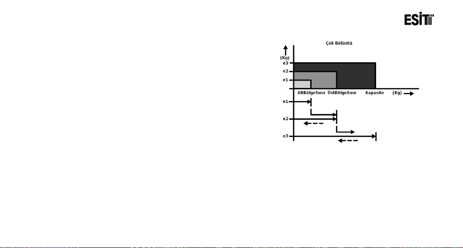
Multi Partition: In this operation there are 3 different scale intervals
and capacities. There is a different scale interval in each capacity
range;
e1 (first zone scale interval): is determined with Resolution
parameter
e2 = 2*e1 (the second zone scale interval): is determined
automatically
e3 = 2*e2 (the third zone scale interval): is determined automatically
If the respective zone capacity +9e is observed when the weight is
increased, it is proceeded to the next scale interval. However, the
scale interval does not change when shifting from the 3. zone to the
2. one or from the 2. zone to the 1. one when the weight is
decreasing. It is shifted to e1 when the weight is below 0,5 e(i).
The scale interval can be the multiples of 1,2 and 5. For example when e1=2, e2=2*e1=2*2=4 and calculated as 5
which is the next scale interval. It is shifted to 3 partition operation mode when the measuring type is selected as "Multi
Interval" or "Multi Partition". In such case, following menus are displayed respectively in order to determine t he upper
and lower Zone limits.In multi partition systems Capacity>UpperZoneLimit>LowerZoneLimit must be entered.
Page 92
Page 93
ECI Multi Functional Weighing Controller Operating Manual
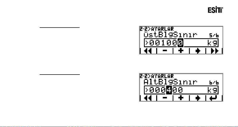
UpperZoneLimit:
It is activated when the measuring type is selected
as "Multi Interval" or "Multi Partition". It is the
maximum value that relates to the 2. scale interval
(e2).
LowerZoneLimit:
It is activated when the measuring type is selected
as "Multi Interval" or "Multi Partition". It is the
maximum value that relates to the 1. scale interval
(e1).
Page 93
Page 94
ECI Multi Functional Weighing Controller Operating Manual
Filter
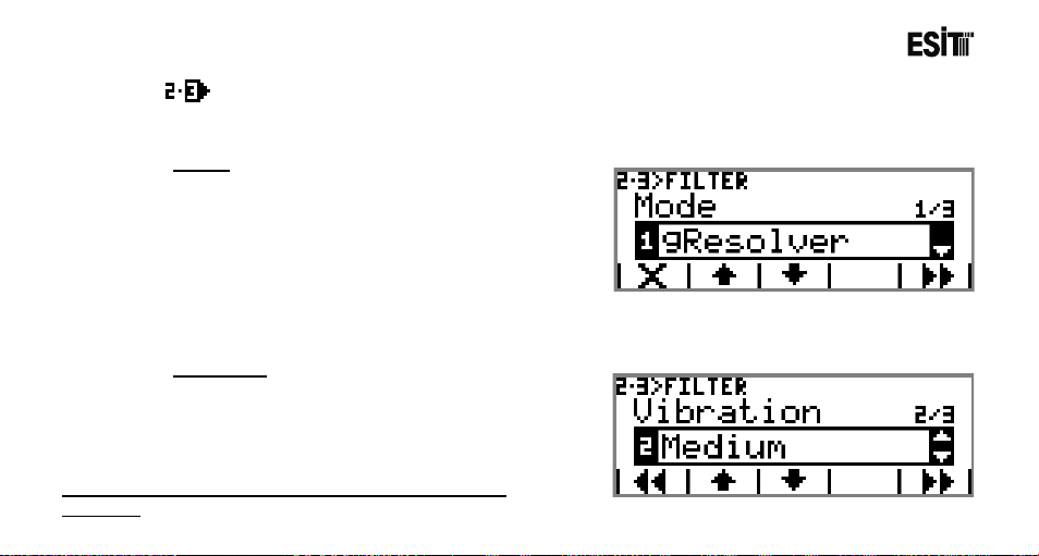
It is the menu where the filter settings are made. This menu is an ordered type menu. The sub-menus are
"Mode", "AverageQuantity", "Speed", "Vibration" and "Stability Period".
Mode
It is the filter mode selection. The options are;
1) Gresolver: It is the advanced numerical filtering
option. The input signal is processed through
advanced mathematical functions and gives rapid and
stable results.
2) Moving Average: It is the standard numerical
filtering option. Moving average method is used.
3) No Filter: No filter is applied.
Vibration
It is the selection for the vibration intensity in the
environment. The options are;
1) Low
2) Medium
Note: When Moving Average is selected no "Vibration" is
displayed.
Page 94
3) High
Page 95
ECI Multi Functional Weighing Controller Operating Manual
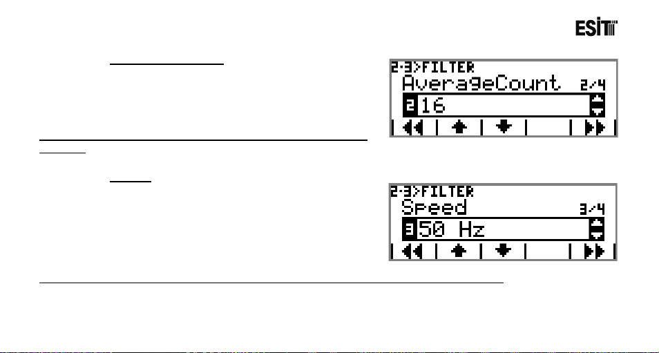
Average Quantity
The selection for the number data to be used for the
moving average filter. The options are;
1) 8
2) 16
Note: When gResolver mode is selected, "AverageQuantity" is not
displayed
Note: When gResolver mode is selected, "Speed" is not displayed It is detected automatically.
Page 95
3) 32
Speed
It is the ADC measuring speed. The options are;
1) 6.25 Hz
2) 12.5 Hz
3) 50 Hz
4) 100 Hz
5) 400 Hz
6) 800 Hz
Page 96
ECI Multi Functional Weighing Controller Operating Manual
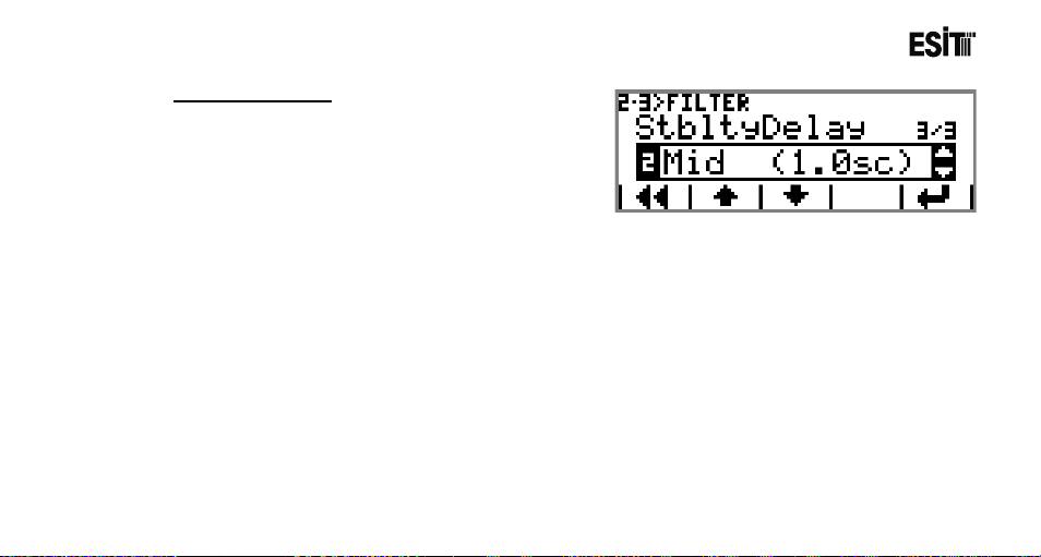
Stability Period
The options are;
1) Short (0.5 sec): Current measurement value is
monitored for 0,5 sec.
2) Medium (1.0 sec): Current measurement value is
monitored for 1 sec.
3) Long (2.0 sec): Current measurement value is
Page 96
monitored for 2 sec.
Page 97
ECI Multi Functional Weighing Controller Operating Manual
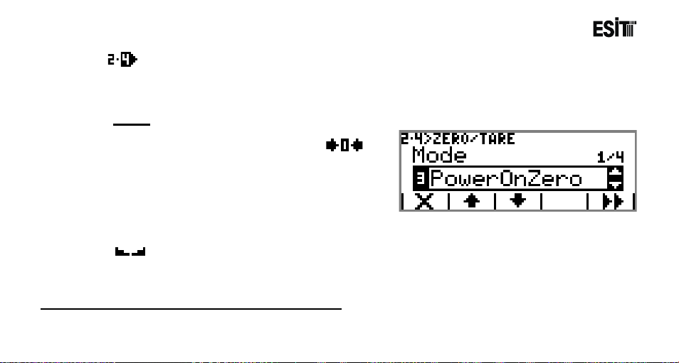
Zero/Tare
It is the menu where the zeroing and taring are made. This menu is an ordered type menu. The
sub*menus are "Mode", "Zero Limit", "Starting Zero" and "Stagnancy".
Mode
The options are;
1) Manuel: Zeroing is only made by using
key.
2) Zero Monitoring: The shifts in the weight value
are zeroed as long as the gross value is zero.
3) Start-up: The option of zeroing at start-up. It
operates with the % ratio selected in "Start-up Zero"
menu. Zero monitoring is also active.
4) Auto-Zeroing: It is the full automatic zeroing option. Start-up is also active. In case of stagnancy (
), the screen is resetted in the % ratio as selected in "Zero Limit" menu once in every 3 seconds.
Note: Zero Monitoring operates only in Indication program.
Page 97
Page 98
ECI Multi Functional Weighing Controller Operating Manual
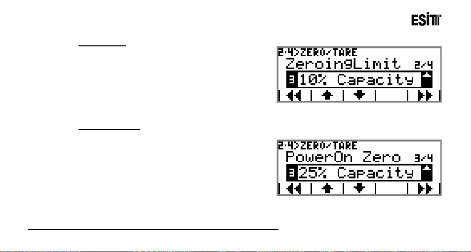
Zero Limit
1) %1 Capacity: Zeroing is made if the weight value
of less than 1 % of the Capacity.
2) %2 Capacity: Zeroing is made if the weight value
of less than 2 % of the Capacity.
3) %10 Capacity: Zeroing is made if the weight value
of less than 10 % of the Capacity.
Start-up Zero
Determines at which ratio of the "Capacity" value will the zeroing be made at first start-up of the device.
The options are;
1) %5 Capacity: Zeroing is made if the weight value
of less than 5 % of the Capacity.
2) %10 Capacity: Zeroing is made if the weight
value of less than 10 % of the Capacity.
3) %25 Capacity: Zeroing is made if the weight value
of less than 25 % of the Capacity.
Note: The start menu is not displayed when "Manuel" mode is selected.
Page 98
Page 99
ECI Multi Functional Weighing Controller Operating Manual
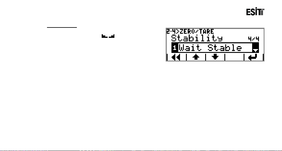
Stagnancy
The options are;
1) Stab.Wait: Stagnancy( ) is necessary for
taring and zeroing. If there is no stagnancy warning
message is displayed on the screen.
2) Always: Tari ng and zeroing is made regardless of
stagnancy.
Page 99
Page 100
ECI Multi Functional Weighing Controller Operating Manual
Calibration
It is explained in detail in Calibration section.
Service
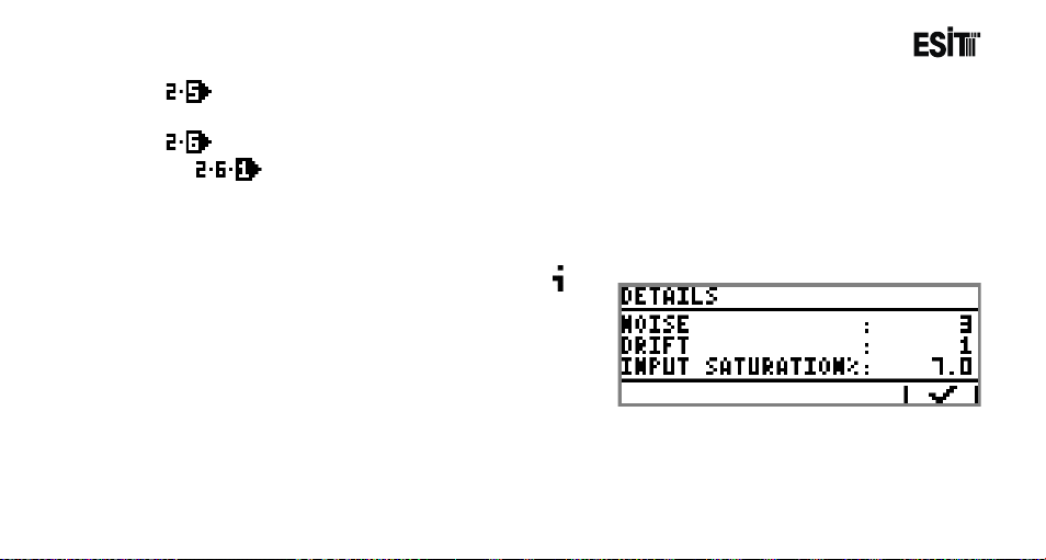
Sys.Doctor
System doctor interprets the values obtained from the load cell and provides detailed information on
the ambient vibration, load status and drift.
Detailed information can be seen by pressing
key.
Noise: Provides the ambient vibration.
Drift: Shows that the load is not stable and has the
tendency to dislodge continuously.
Entry Saturation: Provides the capacity
percentage of the load cell used.
Page 100
 Loading...