

Page 1

IP Server 900
Hardware Installation Manual
Copyright © 2013 ESI (Estech Systems, Inc.).
IVX is a registered trademark of Estech Systems, Inc. Ethernet is a registered trademark of
Xerox Corporation. Motorola and ColdFire are registered trademarks of Motorola, Inc. Rayovac is a
registered trademark of Rayovac Corporation. Act! is a registered trademark of Sage Software, Inc.
Goldmine is a trademark of Goldmine Software Corporation. Microsoft, Windows, Word, NT and
Outlook are registered trademarks of Microsoft Corporation. Panasonic and DBS are registered
trademarks of Matsushita Electric Corporation of America. Novell and Netware are registered
trademarks of Novell, Inc. Smart Jack is a trademark of Westell Technologies, Inc. Information
contained herein is subject to change without notice. Certain features described herein may not be
available at initial release. ESI products are protected by various U.S. Patents, granted and pending.
Visit ESI at www.esi-estech.com.
0450-1305
Rev. E
Page 2
TABLE OF CONTENTS
Overview ........................................................................ A.1
Master Control Unit .................................................................... A.1
Main board .................................................................................. A.1
Memory Module .......................................................................... A.1
Power supply .............................................................................. A.2
Module options ........................................................................... A.2
Cautions and regulatory information ......................... B.1
Cautions ...................................................................................... B.1
Regulatory Information ............................................................... B.2
Précautions et informations réglementaires ............. B.3
Précautions ................................................................................. B.3
Informations réglementaires ...................................................... B.4
Ordering and installing PRI circuits ............................ C.1
PRI configuration description ..................................................... C.1
System capacities......................................................... D.1
Licensing ....................................................................... E.1
Phones ............................................................................ F.1
ESI IP phones .............................................................................. F.1
ESI digital phones........................................................................ F.2
ESI Cordless Handsets ............................................................... F.3
Expansion Consoles ................................................................... F.4
Phone overlays ............................................................................ F.4
VIP 7 Softphone........................................................................... F.4
Hardware installation ................................................... G.1
Site location ................................................................................ G.1
IP 900 D/A Carrier Card installation instructions ...................... G.1
IP Server 900 module installation instructions .......................... G.2
IP Server 900 IP Resource Module installation instructions .... G.3
About replacing modules ........................................................... G.4
Memory Module installation or replacement ............................. G.5
LED functions ............................................................................. G.5
ESI Presence Management installation .................................... G.5
External connections ................................................... H.1
Grounding instructions ............................................................... H.1
Power .......................................................................................... H.1
MOH port .................................................................................... H.3
External paging device connection ........................................... H.3
CO line connection ..................................................................... H.3
Module connections ................................................................... H.3
60-Key Expansion Console connection .................................... H.4
60-Key Second Expansion Console connection ...................... H.5
Installing ESI’s Cordless Handsets ........................................... H.6
Index
Important: For information concerning the programming of an IP Server 900, see the IP Server 900 Programming
Manual (ESI document # 0450-1307).
Page 3
IP Server 900 Hardware Installation Manual Overview
A.1
D/A Module Slot 1
D/A Module Slot 2
D/A Module Slot 3
D/A Module Slot 1
D/A Module Slot 2
D/A Module Slot 3
D/A Module Slot 4
Main Board
Carrier Card
WAN
LAN
USB
Modular RJ
-
45
EXP1 EXP2 EXP3
eSATA
Overview
Master Control Unit
PWR
UIP Module Slot R1
G.729a Module Slot R2
D/A Module Slot 4
MOH,
Compact
Paging,
Flash
IP Server 900 Master Control Unit Layout
Modular RJ-45
Plugs
Jacks
The IP 900 Master Control Unit is designed for easy installation and component access. It houses the
IP Server 900’s main board, a CompactFlash® Memory Module1 socket, and external connections for a power
supply, Music On Hold (MOH), an external paging system, a USB or eSATA drive for ESI Media Management,
LAN and WAN, and RJ-45 plugs for modules (see “Module options,” page A.2). The IP 900 Master Control Unit
measures 16.5″ W × 1.5″ H × 11.75″ D.
Note: The IP Server 900’s eSATA drive port does not support device “hot-plugging” or “hot-swapping” operations.
Power down the system, install the eSATA storage device, and reboot to synchronize the storage device
with the IP Server 900.
Main board
The main board combines leading-edge hardware components — including a Motorola® ColdFire® processor
and DSP structure — along with proprietary operating system software. The board provides system control of the
Memory Module, control of all modules and expansion cabinets, a built-in Network Services Processer (NSP)
which provides remote access via TCP/IP and supports certain optional ESI PC software applications, and builtin Application Services Card (ASC) functionality.
The main board offers 64 universal IP (UIP) ports, expandable to 127 ports with a UIP resource module. It
also accepts a G.729a resource module which provides an optional 48 sessions of the G.729a audio codec for
use on SIP COs or ESI-Link channels. In addition, it allows up to four analog or digital (D/A) modules (see
“Module options,” page A.2), and connects to an optional expansion carrier card that allows up to four more
modules. For ESI Media Management, the built-in ASC functionality allows 32 channels of call recording and 12
channels of video recording.
Memory Module
The Memory Module — a CompactFlash with proprietary formatting — contains all system programming,
configuration data, and pre-loaded voice prompts. The Memory Module provides voice storage of 140 hours at
64 kilobits per second — the industry's highest-quality sampling rate.
1
CompactFlash Memory Modules and system modules are packaged separately and are mounted in the system’s cabinet during installation.
Page 4
IP Server 900 Hardware Installation Manual Overview
A.2
Power supply
The Master Control Unit includes a 33 VDC, 80-watt power supply prepackaged.
Optional rack-mount Power Distribution Shelf
An optional Power Distribution Shelf is available that can be mounted in a standard 19-inch rack. Each
Power Distribution Shelf, which can hold up to six power supplies, includes a six-outlet power strip with on/off
switch and 15' power cord.
Module options
The IP Server 900 supports a wide range of modules with capacities as shown below:
Module
4-FXO
4-FXS
D8
T1/PRI
UIP
G.729a
Phones COs
4 Analog
4 Analog
8 digital
63 UIP ports for ESI IP phones, SIP phones, or SIP COs
24 (T1)
or 23B +1D (PRI)
48 simultaneous channels using
G.729a codec
ESI-Link
channels
Maximum Modules1
8
8
8
2
(1 per Carrier Card • 2 per system)
1
1
Module descriptions
• 4-FXO — Provides circuits for up to four analog loop-start CO lines. This card uses four CO ports.
Note: Ground-start CO lines are not supported.
• 4-FXS — Connects up to four analog devices, such as fax machines and cordless phones. This module
uses four phone ports and no CO ports. Each port provides a standard 24-volt, two-wire phone
connection. Only one analog device can be connected to each port.
• D8 — Connects up to eight ESI digital phones. This module uses eight phone ports and no CO ports.
• T1/PRI — Provides either a T1 interface supporting 24 DS0 channels or an ISDN PRI interface
supporting 23 B (bearer) channels and one D (datalink) channel.
Note: A jumper must be installed on pins 7 and 8 of J2 to enable ISDN PRI functions. The module
• UIP — Provides 63 universal IP ports which can be used for any combination of: local or remote ESI IP
phones, local or remote SIP phones, SIP COs, or ESI-Link channels. This module must be installed in the
slot closest to the rear of the MCU. This slot is labeled with white silkscreen on the main board as UIP
MODULE.
Note: SIP phones and SIP COs require additional licensing.
• G.729a — Provides 48 G.729a sessions for use on SIP COs or ESI-Link channels. This module must be
installed in the slot closest to the front of the MCU. This slot is labeled with white silkscreen on the main
board as CODEC MODULE.
supports, and any or all of the available channels can be assigned as, loop-start, ground-start, E&M
or DNIS/DID CO types with immediate, wink-start, or dial-tone-start signaling. This module is
equipped with a built-in CSU that can be connected directly to a network interface unit, SmartJack, or
ISDN PRI. All 24 CO ports are allocated (regardless of whether they are assigned or used).
1
The maximum module capacity is also dependent on the system’s dialing plan (four-digit or three-digit).
Page 5
IP Server 900 Hardware Installation Manual Cautions and regulatory information
B.1
Cautions and regulatory information
Cautions
Important: This information complies with the requirements of Underwriters’ Laboratories (UL) and UL Standards 1950,
When using this telephone equipment, always exercise basic safety precautions in order to minimize the risk of fire,
electric shock or injury to persons. Before proceeding, please read the following:
• Do not use liquids or aerosols to clean any system equipment; rather, use a cloth that is only slightly damp.
• The ESI system contains no components that are serviceable by either non-Resellers or non-manufacturer
technicians. All service must be referred to the Reseller for further handling.
• Do not install the cabinet in areas with extreme heat or improper ventilation.
• Install the cabinet only in “low-traffic” or “non-public” areas.
• To reduce the risk of fire, use only 24 AWG or larger telecom wire.
60950, and 60950-1, as applicable.
Power supply
Heed all warnings and instructions in documentation or marked on the cabinet or peripheral equipment.
Fuse
Contact the factory before attempting to replace the fuse. The fuse is located on the main board in the Master
Control Unit, and on the backplane in an Expansion Unit.
Battery (located on the main board)
Caution: There is a risk of explosion if the onboard battery is replaced by an incorrect type. Replace only with Ray-O-Vac
BR1225 (or equivalent). Dispose of used batteries according to the battery manufacturer’s instructions.
Notice: This product is intended to be supplied by a Listed Direct Plug-In Power Unit marked ‘Class 2’ and provided
with electrical ratings.
Page 6

IP Server 900 Hardware Installation Manual Cautions and regulatory information
B.2
Regulatory Information
United States of America
Registration
The CO line telephone numbers, FCC registration number, and ringer equivalence number (REN) of this
equipment must be provided to the telephone company before installation. (See below for FCC registration
number and ringer equivalence number.)
FCC Part 15
This equipment has been tested and found to comply with the limits for a Class A digital device, pursuant to
Part 15 of the FCC Rules. These limits are designed to provide reasonable protection against harmful
interference when the equipment is operated in a commercial environment. This equipment generates, uses
and can radiate radio frequency energy and — if not installed and used in accordance with the instruction
manual — may cause harmful interference to radio communications (in which case, the user will be required
to correct the interference at his/her own expense).
FCC Part 68
This equipment complies with Part 68 of the FCC Rules. On the bottom of this equipment is a label that
contains, among other information, the FCC Registration Number and Ringer Equivalence Number (REN) for
this equipment. You must, upon request, provide this information to your telephone company.
The REN is helpful to determine the quantity of devices you say connect to your telephone line and still have
all of those devices ring when your telephone number is called. In most, but not all, areas, the sum of the
RENs of all devices connected to one line should not exceed five (5.0). To be certain of the number of devices
you may connect to your line, as determined by the REN, you should contact your local telephone company
to determine the maximum REN for your calling area.
If your telephone equipment causes harm to the telephone network, the telephone company may discontinue
your service temporarily. If possible, the telephone company will notify you in advance but, if advance notice
is not practical, you will be notified as soon as possible. You will be informed of your right to file a complaint
with the FCC.
Your telephone company may make changes to its facilities, equipment, operations or procedures that could
affect the proper functioning of your equipment. If so, you will be notified in advance, to give you an
opportunity to maintain uninterrupted telephone service.
If you experience trouble with this telephone equipment, the telephone company may ask that you disconnect
this equipment from the network until the problem has been corrected or until you are sure that the equipment
is not malfunctioning.
This equipment may not be used on coin service provided by the telephone company. Connection to party
lines is subject to state tariffs.
Installation: The device is equipped with a T568B connector.
Registration Number: 1T1MF08B33727.
Ringer Equivalence Number (REN): 0.8.
Hearing-aid compatibility
This equipment, utilizing telephone phone equipment manufactured by ESI, meets all FCC requirements for
hearing-aid compatibility.
Page 7
IP Server 900 Hardware Installation Manual Cautions and regulatory information
B.3
Précautions et informations réglementaires
Précautions
Important: Cette information est conforme aux exigences des Underwriters’ Laboratories (UL) et les normes UL 1950,
Lorsque vous utilisez cet équipement téléphonique, toujours prendre les précautions de sécurité élémentaires
afin de minimiser les risques d'incendie, d'électrocution ou de blessures. Avant de procéder, s'il vous plaît
lisez ce qui suit:
• N'utilisez pas de liquides ou d’aérosols pour nettoyer tout l’équipement du système, mais plutôt utiliser un
chiffon qui est seulement légèrement humide.
• Le système ESI ne contient aucun composant qui sont utilisables soit par non-revendeurs ou de non-fabricant
de techniciens. Tous les services doivent être soumis au revendeur pour la manipulation.
• Ne pas installer l'armoire dans les zones à la chaleur extrême ou une mauvaise ventilation.
• Installez l'armoire que “à faible trafic” ou “non-public” domaines.
• Pour réduire le risque d’incendie, utiliser seulement 24 AWG ou plus gros fil de télécommunications.
60950, et 60950-1, le cas échéant.
Alimentation
Respectez tous les avertissements et les instructions dans la documentation ou marqué sur le boîtier ou de
l’équipement périphérique.
Fusible
Contactez l’usine avant de tenter de remplacer le fusible. Le fusible est situé sur le tableau principal à l’Unité de
Contrôle Maître, et sur le fond de panier dans une Unité d’Extension.
Batterie
Attention: Il ya un risque d’explosion si la batterie embarquée est remplacé par un type incorrect. Remplacer
Avis: Ce produit est conçu pour être alimenté par un directs énumérés Plug-In Power Unit marqué ‘classe 2’ et
uniquement avec Ray-O-Vac BR1225 (ou équivalent). Jetez les batteries usagées conformément aux
instructions du fabricant de batteries.
fourni avec notes d’électricité.
Page 8

IP Server 900 Hardware Installation Manual Cautions and regulatory information
B.4
Informations réglementaires
États-Unis d’Amérique
Enregistrement
Les numéros de CO ligne téléphonique, le numéro d’enregistrement FCC et le numéro d’équivalence
sonnerie (REN en anglais) de cet équipement doit être fourni à la compagnie de téléphone avant l’installation.
(Voir ci-dessous pour le numéro d’enregistrement FCC et le numéro d’équivalence sonnerie.)
La Partie 15 des Règlements de la FCC
Cet équipement a été testé et trouvé conforme aux limites pour un numérique de classe A, conformément à
la Partie 15 des règlements de la FCC. Ces limites sont conçues pour fournir une protection raisonnable
contre les interférences nuisibles lorsque l’équipement est utilisé dans un environnement commercial. Cet
équipement génère, utilise et peut émettre des fréquences radio et — s’il n'est pas installé et utilisé
conformément aux instructions du manuel — peut provoquer des interférences nuisibles aux communications
radio (dans ce cas, l’utilisateur devra corriger l’interférence à son/sa propres frais).
La Partie 68 des Règlements de la FCC
Cet équipement est conforme à la Partie 68 des règlements de la FCC. Sur le fond de cet équipement est
une étiquette qui contient, entre autres informations, le numéro d’enregistrement FCC et le numéro
d’équivalence sonnerie (REN en anglais) pour cet équipement. Vous devez, sur demande, fournir cette
information à votre compagnie de téléphone.
Le REN est utile pour déterminer la quantité d’appareils que vous dites se connecter à votre ligne
téléphonique et ont encore tous ceux qui sonneront quand votre numéro de téléphone est appelé. Dans la
plupart, mais pas tous, régions, la somme des REN de tous les appareils connectés à une ligne ne doit pas
dépasser cinq (5,0). Pour être certain du nombre de dispositifs que vous pouvez brancher à votre ligne, tel
que déterminé par le REN, vous devriez communiquer avec votre compagnie de téléphone locale afin de
déterminer le REN maximum pour votre zone d’appel.
Si votre équipement téléphonique cause des nuisances au réseau téléphonique, la compagnie de téléphone
peut interrompre votre service temporairement. Si possible, la compagnie de téléphone vous avisera à
l’avance, mais, si un préavis n’est pas pratique, vous serez avisé dès que possible. Vous serez informé de
votre droit de déposer une plainte auprès de la FCC.
Votre compagnie de téléphone peut apporter des changements à ses installations, équipements, opérations
ou procédures pouvant affecter le bon fonctionnement de votre équipement. Si oui, vous en serez informé à
l’avance, pour vous donner une chance de maintenir un service téléphonique sans interruption.
Si vous rencontrez des problèmes avec cet équipement téléphonique, la compagnie de téléphone peut vous
demander de déconnecter cet équipement du réseau tant que le problème a été corrigé ou jusqu'à ce que
vous êtes sûr que le matériel n’est pas défectueux.
Cet équipement ne peut être utilisé avec les services payants fournis par la compagnie de téléphone.
Connexion à des lignes est soumis aux tarifs locaux.
L’installation: L’appareil est équipé d’un connecteur T568B.
Numéro d'Enregistrement: 1T1MF08B33727.
Numéro d’Équivalence Sonnerie (REN en Anglais): 0.8.
Prothèse Auditive Compatibilité
Cet équipement, en utilisant l’équipement poste téléphonique fabriqué par ESI, respecte toutes les exigences
de la FCC pour la compatibilité des prothèses auditives.
Page 9
IP Server 900 Hardware Installation Manual Ordering and installing PRI circuits
C.1
Ordering and installing PRI circuits
This section addresses things to consider when ordering and installing ISDN PRI circuits on the IP Server 900.
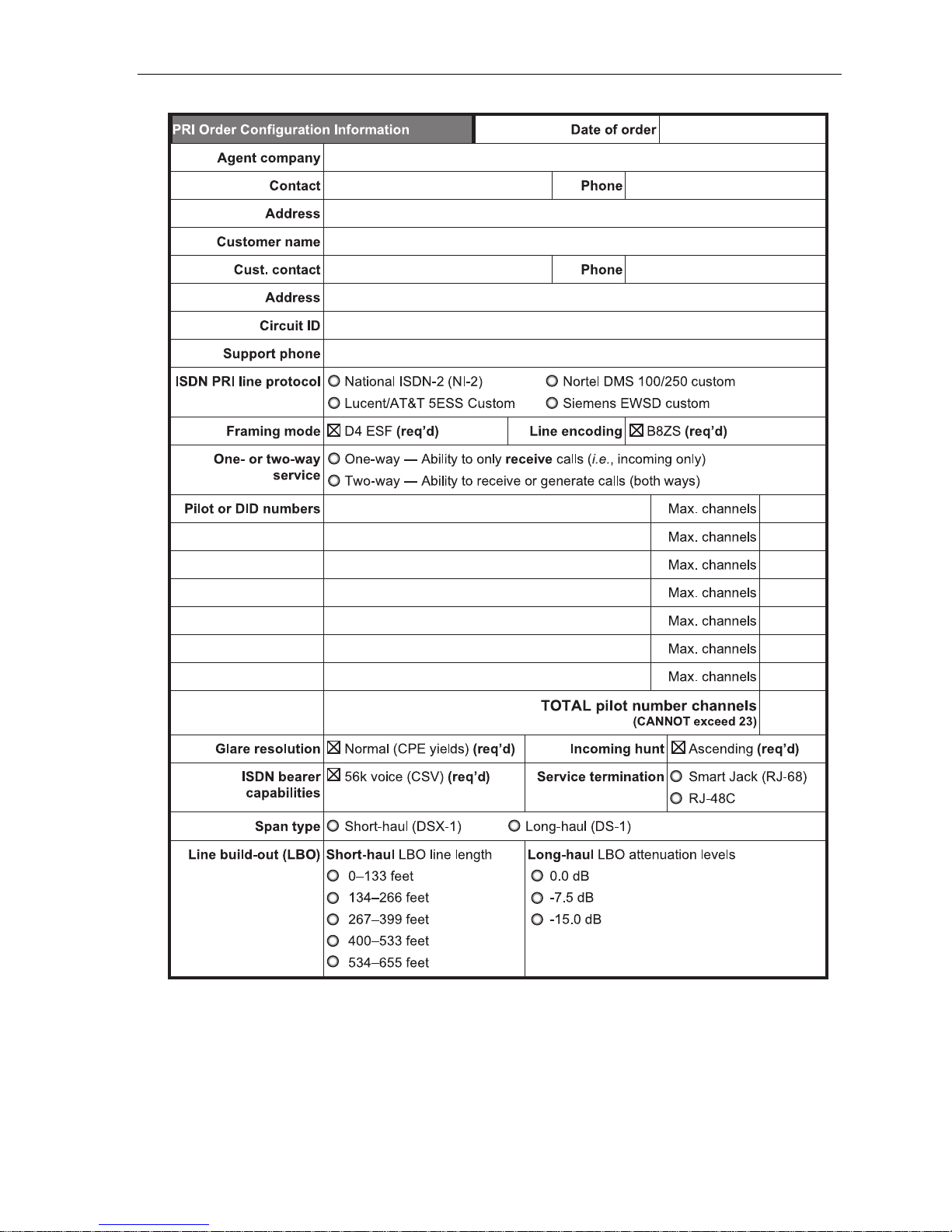
When ordering and provisioning such circuits, you must correctly define certain parameters in order for the PRI
to function correctly. This section is a template for a PRI order form you can use to order PRI circuits that — if
provisioned according to the order form — will be fully compatible with the IP Server 900.
PRI configuration description
• Agent Company — The name of the company ordering the PRI on behalf of the customer.
• Contact — The individual placing the PRI order.
• Address — Address of the agent company.
• Customer Name — The name of the end user’s company.
• Circuit ID — The circuit number (or sequence of characters and numbers) that the service provider uses to
identify the PRI circuit. This is used for identification when troubleshooting or reporting issues.
• Support Phone Number — The service provider’s Customer Service phone number.
• PRI Line Protocol — The ISDN protocol offered by the service provider. ESI strongly recommends using the
NI-2 (National ISDN-2) protocol.
• Framing and Line Encoding — You must use ESF (extended super frame) framing and B8ZS (binary eight-
zero substitution) encoding.
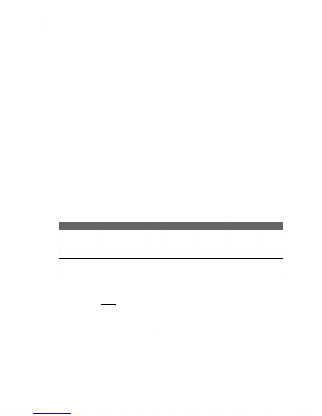
• Pilot/DID Numbers — In the IP Server 900 number delivery on a PRI circuit is separated into pilot numbers
and Direct Inward Dialing (DID) numbers. It can support up to 100 pilot numbers and up to 600 DID numbers.
DID numbers are dedicated to ring to a specific phone or department and can come in on any PRI channel. Pilot
numbers ring down a specific PRI channel or group of channels, typically referred to as a hunt group. When you
create a pilot number in the IP Server 900 you must enter the maximum number of PRI “B” channels (one to 23)
that can be used for that pilot number’s hunt group. For example:
Pilot number Name Chs. Day ring 1 Day ring 3 Day ring 5 Day ring 9
2145554378 ABC SYSTEMS 10 Dept. 290
2145552390 ABC SYS SVC 9 Dept. 291
2145555678 ABC SYS INTL 4 X100, X101 X100, X101 X102 Dept. 290
Important: The total number of channels assigned across all pilot numbers should not exceed 23. Exceeding this
limit may cause system instability.
• Glare Resolution — Glare is a condition wherein an outgoing call and an incoming call attempt to seize the
same circuit at the same time. On loop-start analog lines this usually causes the two callers to be connected
because loop-start lines do not manage glare resolution. PRI COs, however, utilize glare resolution protocols
that define what the CO will do with a call if glare is detected. The IP Server 900 requires that connected PRI
circuits be set to the normal (also called standard) protocol rather than the yielding protocol. This means that
the system will block the outgoing call if glare is detected.
• Incoming Hunt — In order to help prevent glare, PRI providers will attempt to send calls down the PRI in the
opposite order that the phone system attempts to send them out. The IP Server 900 sends calls out in a
descending order, meaning the first call goes out channel 23. When ordering the PRI the service provider
needs to set the circuit to hunt in an ascending order, meaning incoming calls will start at channel one.
• ISDN Bearer Capabilities — This is the supported PRI feature set. The IP Server 900 supports only 56K
voice (CSV).
Page 10
IP Server 900 Hardware Installation Manual Ordering and installing PRI circuits
C.2
• Service Termination — ESI recommends that the PRI circuit be terminated on an eight-pin RJ-68 (also called
a SmartJack). If an RJ-68 isn’t available, you may use an eight-pin RJ-48 jack. If you use an external Channel
Service Unit (CSU) be sure to turn off the internal CSU in the IP Server 900.
Important: ESI recommends using Category 5 (or better) twisted-pair cable with a length of at least six feet when
connecting a cable between the PRI and CSU or Smart Jack.
• Span Type — When the distance from the IP Server 900 to the CSU, SmartJack, or multiplexer (all of which
are considered repeaters) is less than 655 feet use the DSX-1 setting. For longer distances use DS-1. This
value is used in combination with the Line Build-Out setting below to define loss levels and compensation
when programming the PRI circuit in the IP Server 900.
• Line Build-Out (LBO) — For long-haul (DS-1 span) circuits, the CSU must usually be set to correct for signal
loss across the longer cabling. This is called Line Build-Out, and is used in combination with Span Type
setting above to determine the attenuation levels used by the IP Server 900.
Note: The sample order form template on the next page is available on the ESI Web site. There you can
download a Microsoft Word document version — listed as Technical Update #176 — that can be filled
out on a PC.
Page 11
IP Server 900 Hardware Installation Manual Ordering and installing PRI circuits
C.3
Page 12

IP Server 900 Hardware Installation Manual System capacities
D.1
System capacities
Important: Each ESI Presence Management RFID Reader (digital model) consumes one digital phone port.
Phones and COs
The specifications shown below reflect system maximum capacities and configurations. Not all of the phone and
CO maximums can be reached simultaneously.
Maximum modules 8 8
Dialing plans (-digits)
CO Line groups 9, 8, 71–76 Yes Yes
SIP CO capability Yes Yes
Maximum port configuration1 500 400
– Maximum phones 191 168
– Maximum IP phones 127 127
– Maximum digital phones 64 64
– Maximum analog phones 32 32
Maximum CO lines 192 84
– Maximum T1/PRI Modules 2 2
– ESI-Link channels 127 127
– Total number of SIP COs 127 84
Max. members, CO ring assignment list 64 64
Dedicated ports
Dialing plans (-digits)
Voice mail/auto attendant ports 32 32
Conference ports
(max. of 16 members per conference)
Overhead paging ports 1 1
Serial/SMDR ports n/a n/a
Four Three
Four Three
64 64
Departments
Max departments 64 20
Dialing plans (-digits)
Department types: Ring-all, ACD, UCD, inorder, pick-up, attendant
Max members, non-ring-all depts. 64 64
Max members, ring-all depts. 64 64
Four Three
Yes Yes
Automatic Call Distribution (ACD)
Max ACD departments 64 64
Dialing plans (-digits)
Max ACD agents per department 64 64
Max ACD agents (system-wide) 191 168
Four Three
Shared-office tenanting
Tenants 8 8
Dialing plans (-digits)
Four Three
Translation tables
Pilot numbers 100 100
Dialing plans (-digits)
Max. DID entries 600 600
Four Three
1
Includes ESI-Link channels.
Page 13

IP Server 900 Hardware Installation Manual System capacities
D.2
System speed-dial numbers
System speed-dial numbers 1,000 100
Dialing plans (-digits)
Four Three
Voice mail capacities
Voice mail storage (hours) 140 140
Dialing plans (-digits)
Broadcast mailbox (one to all extensions) Yes Yes
Cascade notification mailboxes 20 10
Group mailboxes/max. members 32/64 32/64
Guest/info mailboxes 1,000 190
Maximum phone mailboxes 191 168
Q & A mailboxes 20 10
Four Three
Maximum installations of VIP 7 applications
Installations, VIP 7 PC Attendant Console 8 8
Dialing plans (-digits)
Installations, VIP 7 ACD Supervisor 8 8
Four Three
ESI Presence Management features
RFID Reader access door records 10,000 10,000
Dialing plans (-digits)
RFID Reader entries in Fn. 3721 32 32
Max. RFID tags (“electronic keys”) 500 500
Four Three
ESI Mobile Messaging features
Maximum phones 191 168
Dialing plans (-digits)
Maximum guest mailboxes 250 250
Four Three
ESI Video Viewer and ESI Video Adapters
ESI Video Adapters (see below) 12 12
RFID Readers per ESI Video Adapter 1 1
User extns./depts. per ESI Video Adapter 64 64
ESI Video Viewer users 20 20
Dialing plans (-digits)
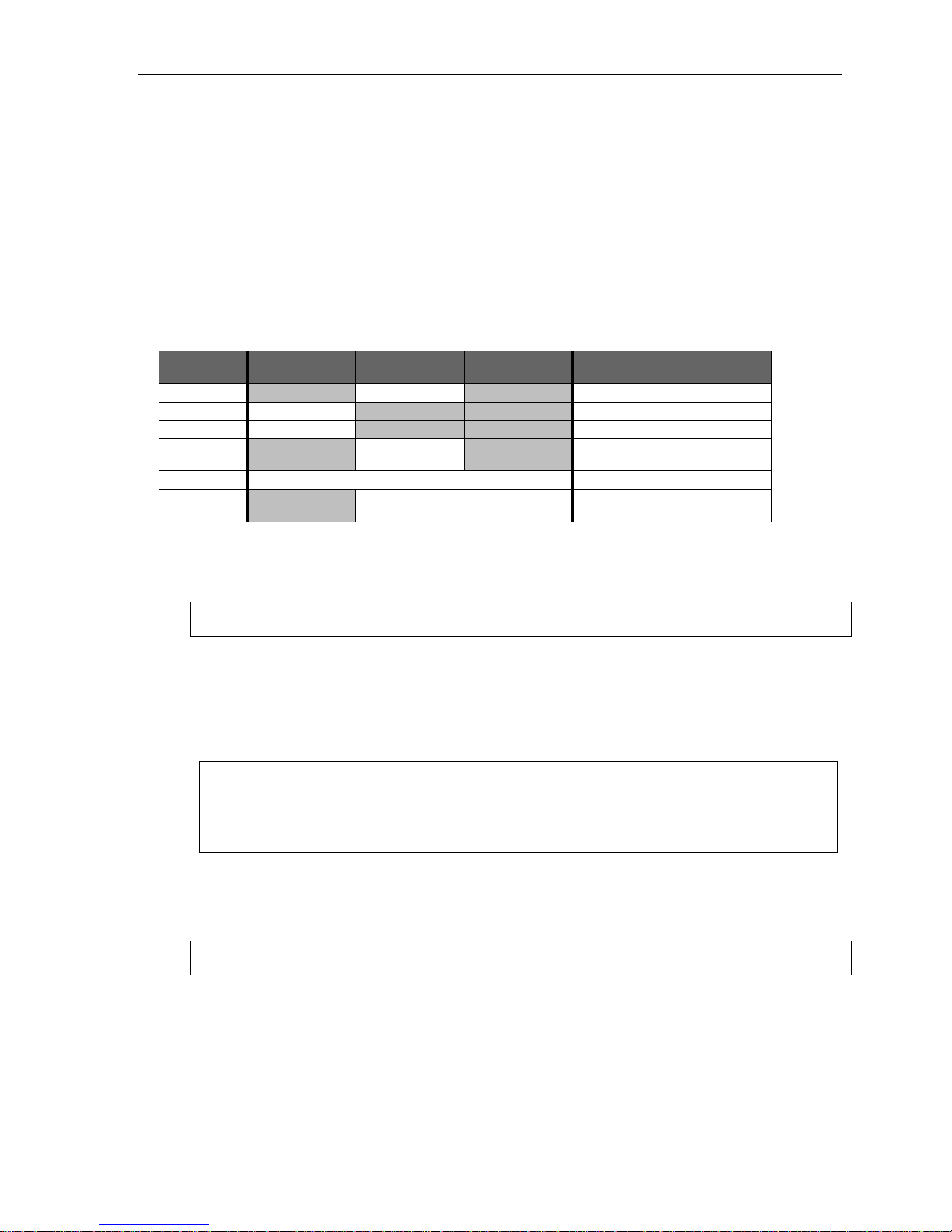
Although the system supports up to 12 cameras, a variety of other factors can affect the maximum number of usable cameras.
The frequency and duration of video recordings from each camera as well as overall network load to the system — such as
local or remote IP phones, SIP trunks, SIP stations, and usage of ESI applications (e.g., ESI Mobile Messaging, VIP 7, or
ESI Presence Management) — can severely impact the performance of both the cameras and the IP Server 900. The following
chart can be used as a general guideline for determining the number of cameras supported based on system configuration
and usage:
Number of users Light usage Medium usage Heavy usage
20
40
60
120
12 cameras 12 cameras 10 cameras
12 cameras 10 cameras 8 cameras
10 cameras 8 cameras 5 cameras
8 cameras 6 cameras 4 cameras
Four Three
ESI Media Management features
Video recordings 12 12
Dialing plans (-digits)
Audio recordings 32 32
SMDR events Yes Yes
Fob activity Yes Yes
ESI Media Manager users 20 20
Four Three
1
See the ESI Presence Management Installation Manual (ESI document # 0450-0792).
Page 14

IP Server 900 Hardware Installation Manual Licensing
E.1
Licensing
There are various types of licenses needed to activate certain features and functionality in the IP Server 900.
The following features, products, and capabilities require license activation:
• Universal IP (UIP) Ports used for:
o ESI IP phones
o SIP phones
o SIP CO lines
o ESI-Link channels
o Local IP phone operation
o Remote (off-site) IP phone operation
• ESI Media Management
o Audio recordings
o Video recordings
• ESI Mobile Messaging
• G.729a codec
• SIP CO lines
• SIP phones
1
• Meet-me conferencing
• ESI RFID tags for ESI Presence Management
• ESI Video Viewer
• VIP 72
• VIP 7 ACD Agent
• VIP 7 ACD Supervisor
• VIP 7 PC Attendant Console.
• VIP 7 Softphone
(also requires purchase of local or remote IP phone license)
• Voice mail
o Channels
o Message storage (in hours)
License activation
To have licenses activated by ESI Technical Support:
1. Licenses must already have been ordered from ESI.
2. The IP Server 900 must have either:
• A public IP address assigned to the NSP
3
(with associated port forwarding in NAT environments);
or
• A CO line connected to it (
analog, PRI, or T1).
3. You’ll need the following information to provide to the ESI representative:
• The ESI sales order number.
• The customer (site) name.
• The public IP address of the NSP or the phone number of the CO line.
IP phone licenses
Each IP Phone4 connected to the system will require an available UIP port as well as activation of a UIP license
and any other required license. If a new extension number is assigned to the phone and there are not enough
licenses available, the phone will display the error LICENSE EXCEEDED when connected to the IP Server 900.
It is important to keep this licensing in mind for SIP phones or CO lines, because each SIP phone or CO line will
require not only an available UIP port, but an UIP license and a SIP phone or SIP CO license.
1
ESI desktop IP phones programmed for remote operation can still operate as local phones on the LAN.
2
VIP 7 ACD Agent uses the same license part numbers as VIP 7, allowing mixing and matching as the customer may require; e.g., 100 licenses could
be used for 60 VIP 7 installations and 40 VIP 7 ACD Agent installations. For licensing information for VIP 7 PC Attendant Console and VIP 7 ACD
Supervisor refer to their respective Product Overviews (available from www.esi-estech.com). VIP 7 Softphone is sold as a single license, which
provides one user with VIP 7 features and Softphone-specific capabilities. The VIP 7 Softphone license is selected, at the time of purchase, for local
or remote operation.
3
For more information about the NSP, refer to NSP Installation Made Simple (ESI #0450-0669).
4
An ESI 60 (IP model), ESI 40 (IP model), 48-Key IP Feature Phone II, IP Cordless Handset (Local or Remote), VIP Softphone, or SIP phone.
Page 15

IP Server 900 Hardware Installation Manual Phones
F.1
Phones
ESI IP phones
Current models
• ESI 60 (IP versions) — 10/100 or Gigabit Ethernet. Three-line, 56-character display (adjustable backlit
display available); speakerphone; headset jack; 48 programmable feature keys; supports VIP 7 and the
60-Key Expansion Consoles.
• ESI 40 (IP version) — 10/100 Ethernet. Three-line, 56-character display (adjustable backlit display
available); speakerphone; headset jack; 16 programmable feature keys; supports VIP 7 and the 60-Key
Expansion Consoles.
• 48-Key IP Feature Phone II (includes full duplex and backlit models
speakerphone; headset jack; 30 programmable feature keys; supports VIP 7 and the 60-Key Expansion
Consoles.
• Remote IP Cordless Handset II and Local IP Cordless Handset II -- DECT 6.0 technology; two-line,
32-character display; speakerphone; eight programmable feature keys. Also supports range-extending
Repeater units.
Features and support for standards
1
) — Three-line, 56-character display;
An ESI desktop IP phone looks and works like a regular digital phone as described on page F.2, but connects
from within the local premises via an IP network connection rather than twisted-pair cabling. If used remotely,
an ESI desktop IP phone connects to the IP Server 900 through the public internet. Each ESI desktop IP
phone derives its power from Power over Ethernet (PoE) via either a PoE switch on the local premises, or
through and individual PoE adapter. ESI desktop IP phones support the following features and standards:
• Power via IEEE 802.3af Power over Ethernet (PoE).
• Local or remote (off-site) operation.
• Use the G.711 audio codec in local operation and the G.726 codec during remote operation. The
G.711 transfer rate is 206 Kbps; the G.726 transfer rate is 90 Kbps.
• Use DHCP
2
to obtain an IP address:
– In local operation DHCP can be provided by the IP Server 900 or an external server.
– In remote operation the phone will use the DHCP server at the remote site to obtain its
addressing.
• Complies with IEEE 802.1q and 802.1p (VLAN) Layer 2 switching and prioritization.
• Complies with Layer 3 DiffServ (RFC 2475) Quality of Service (QoS) implementations.
Important: Each ESI IP phone draws up to 7.25 watts3 at 48 volts DC; therefore, each advertises itself to a Power over
Notes: When connecting an ESI desktop IP phone to a PoE source, the PoE cable must be connected to the jack
ESI has tested each ESI desktop IP phone with several PoE sources. For a current list of tested devices,
Ethernet switch as a Class 3 device per the 802.3af standard. Most PoE switches adhering to this standard
will provide up to 12.5 watts for each Class 3 device.
labeled NETWORK on the base of the phone. The jack labeled PC DOES NOT support PoE.
consult the ESI Knowledge Base at http://support.esiresellers.com.
Important: None of the IP phones listed in this section will work with ESI’s legacy IP E-Class or IVX® systems. Similarly,
1
Supported only on software versions 25.1.2.5 and later; see ESI Technical Update 335.
2
Dynamic Host Configuration Protocol, an IP standard described in RFC 2131 (http://www.ietf.org/rfc/rfc2131.txt).
3
An ESI desktop IP phone’s power consumption takes into account an optional 60-Key Expansion Console.
previous IP Feature Phone models (including the Remote IP Feature Phone) don’t work with the IP Server 900
but, instead, are intended for use with only IP E-Class and appropriate IP-enabled IVX systems.
Page 16

IP Server 900 Hardware Installation Manual Phones
F.2
ESI digital phones
The IP Server 900 supports several different models of ESI digital phones, each of which connects to the
cabinet via standard two-wire twisted pair.
Current models
• ESI 60 (digital version) — Three-line, 56-character display with adjustable backlighting; full-duplex, high-
definition speakerphone; headset jack; 48 programmable feature keys; supports VIP 7 and the 60-Key
Expansion Consoles. Available with full-duplex speakerphone and display with adjustable backlighting.
• ESI 40 (digital version) — Three-line, 56-character display with adjustable backlighting; speakerphone;
headset jack; 16 programmable feature keys; supports VIP 7 and the 60-Key Expansion Consoles.
• ESI 30D — Two-line, 32-character backlit display; speakerphone; 12 programmable feature keys.
• 48-Key Digital Feature Phone (includes full-duplex and backlit models
display; speakerphone; headset jack
Expansion Consoles.
2
; 30 programmable feature keys; supports VIP 7 and the 60-Key
1
) — Three-line, 56-character
Note: Not all modular headsets will work on the 48-Key Feature Phone’s headset jack.3 For information on
supported headset models, visit www.plantronics.com or www.jabra.com.
• Cordless Handset II — DECT 6.0 technology; two-line, 32-character display; speakerphone; eight
programmable feature keys. Also supports range-extending Repeater units.
Note: When a desktop phone is in the highest upright position, use the wall-mount hook located under the handset
to secure the handset when you’re not using the phone.
1
Supported only on software versions 25.1.2.5 and later; see ESI Technical Update 335.
2
Headset jack for 48-Key Feature Phones (Digital, Digital TAPI, Local IP, or Remote IP) manufactured after March, 2004 only.
3
Not all handsets are compatible with your ESI phone; contact your ESI Reseller for a list of compatible models. Noise-cancelling headsets are not
compatible with ESI phones.
Page 17

IP Server 900 Hardware Installation Manual Phones
F.3
ESI Cordless Handsets
The IP Server 900 also supports ESI’s digital, Local IP, and Remote IP Cordless Handsets (but only the ESI
Cordless Handset II models, not the original ESI Cordless Handset).
The ESI Cordless Handset II includes seven familiar fixed feature keys, eight programmable feature keys, a
speakerphone, and a headset jack. The Base Phone for the ESI Digital Cordless Handset II uses a standard line
cord and is line-powered. The Base Phone for each ESI IP Cordless Handset II (Local IP or Remote IP) uses
network cabling and receives (and requires) Power over Ethernet (PoE). The ESI Remote IP Cordless Handset II
Base Phone also includes a jack into which the user can plug an analog CO line. This gives the home-based
teleworker the convenience of using both home and business lines with the ESI Remote IP Cordless Handset II.
Each ESI Cordless Handset II model employs advanced DECT 6.0 technology which, as compared to the
original ESI Cordless Handsets, allows more secure communications and — through the use of one or more
optional ESI Cordless Handset II Repeaters — greater range.
Important: Each ESI IP phone draws up to 7.25 watts1 at 48 volts DC; therefore, each advertises itself to a Power over
Ethernet switch as a Class 3 device per the 802.3af standard. Most PoE switches adhering to this standard
will provide up to 12.5 watts for each Class 3 device.
1
An ESI desktop IP phone’s power consumption takes into account an optional 60-Key Expansion Console.
Page 18

IP Server 900 Hardware Installation Manual Phones
F.4
Expansion Consoles
The 60-Key Expansion Console gives a designated user 60 additional programmable feature keys. It is
supported by the ESI 60 (digital or IP models), ESI 40 (digital or IP models), and the 48-Key Feature Phone
(digital or IP models). The Expansion Console is connected to its host ESI phone via a special cable (provided)
and doesn’t require a separate phone port of its own. Additionally, it may be connected to a 60-Key Second
Expansion Console via a special cable (provided with the 60-Key Second Expansion Console) so that one
phone can have a total of 120 programmable feature keys in addition to its own complement of keys.
A fully configured IP Server 900 allows up to 80 phones to have one or two Expansion Consoles (60-Key and
60-Key Second).
Note: The IP 900 Master Control Unit can support a maximum of eight Expansion Consoles, and each Expansion
Unit can support a maximum of 24 Expansion Consoles — for a system maximum of 80 Expansion Consoles.
Phone overlays
Each ESI phone comes with one overlay for the programmable feature keys. To order additional overlays visit
the DESI
software DESI Lite, which allows you to print on the overlays. For assistance with DESI products contact DESI
(the DESI Web site contains contact information).
™
Web site, www.desi.com. While there you may also want to download the free Windows-based
Tip: The browser-based IP Server 900 System Programmer application also lets you print on the overlays.
VIP 7 Softphone
VIP 7 Softphone integrates the features of VIP 7 and an ESI desktop IP phone into a PC-based, full-audio
phone. With the appropriate license, VIP 7 Softphone can be configured for use locally or remotely.
This product requires a PC equipped with either (a.) a third-party USB headset or (b.) a microphone
and speakers.
Note: For details, see the VIP 7 Product Overview and the VIP 7 Setup and User’s Guide; both are available from
www.esi-estech.com.
Page 19

IP Server 900 Hardware Installation Manual Hardware installation
G.1
Hardware installation
Site location
As with most electronic equipment, the environmental considerations for this site need to observe good common
sense. Provide a dry, clean, and accessible area.
Locate space in the telephone equipment room, which will provide easy connection to the termination blocks and
110 VAC power. The location should be no further than 1,000 feet from the farthest phone.
0
Ambient room temperature must be 40
–800 (F.), and relative humidity no higher than 90%.
Notes: Do not place the equipment or run phone cabling near high voltage electrical equipment or electrical lines
susceptible to high voltage surges from air conditioner compressors, etc.
Do not mount the equipment in a place that receives direct sunlight.
IP 900 D/A Carrier Card installation instructions
Important: Before installing, verify that the system is running the appropriate system software. If it isn’t, download the
ALWAYS power-down the system BEFORE adding or replacing any hardware. Also, be sure to
Whenever you change the module configuration, you must create a backup file for the new configuration to
After removing an IP 900 D/A Carrier Card from the box, install it as follows in the IP Server 900.
1. Loosen the two thumbscrews on either side of the Master Control Unit that secure the base tray to the top,
and then slide the bottom tray out and away from the top cover.
2. With the bank of eight RJ-45 connectors facing toward you, align the IP 900 D/A Carrier Card with the six
mounting standoffs. Use the screws that ship with the IP 900 D/A Carrier Card to secure the new IP 900
D/A Carrier Card to the standoffs. (You may have leftover screws.) DON’T over-tighten the screws; it will
strip the standoffs.
3. A cable is attached to connector J20 of the new IP 900 D/A Carrier Card. Connect the cable’s other end to
connector J15 of the Master Control Unit’s main board.
4. Connect the four-wire power cord attached to the IP 900 D/A Carrier Card to the main board of the Master
Control Unit labeled PC POWER (J8).
5. Slide the bottom tray back into the top case, and secure the two pieces together by tightening the
thumbscrews.
6. If you have no more IP 900 D/A Carrier Cards or modules to install at this time, power-up and program
the system.
correct version from the ESI Resellers’ Web site and install it on the system
observe all proper procedures regarding the prevention of electrostatic discharge (ESD) when performing
the following procedures; otherwise circuit boards may suffer damage.
be able to perform the Restore function later.
.
Page 20

IP Server 900 Hardware Installation Manual Hardware installation
G.2
IP Server 900 module installation instructions
Important: Before installing, verify that the system is running the appropriate system software. If it isn’t, download the
ALWAYS power-down the system BEFORE adding or replacing any hardware. Also, be sure to observe
Whenever you change the module configuration, you must create a backup file for the new configuration to
correct version from the ESI Resellers’ Web site and install it on the system.
all proper procedures regarding the prevention of electrostatic discharge (ESD) when performing the
following procedures; otherwise, circuit boards may suffer damage.
be able to perform the Restore function later.
After removing an IP Server 900 module from the box, install it as follows:
1. Loosen the two thumbscrews on either side of the Master Control Unit that secure the base tray to the top,
and then slide the bottom tray out and away from the top cover.
Notes: The main board and IP 900 Carrier Card support the installation of four separate modules on each
Master Control Unit connectors IP 900 D/A Carrier Card connectors
M1 — J12 and J13 M1 — J11 and J13
M2 — J21 and J22 M2 — J15 and J14
M3 — J31 and J32 M3 — J16 and J17
M4 — J40 and J41 M4 — J18 and J19
Each module has a 20-pin and a 40-pin connector, each of which is keyed to allow the module to be
component, allowing up to 8 modules to be installed within the system. Modules are numbered in an
order of 1–4 on each and will be connected using the following connectors:
installed a certain way. Also, modules can be installed in any order, allowing you to skip module
positions, if desired, to save room for later growth.
2. Holding the module with the 40-pin and 20-pin connectors facing towards the Carrier Card, select the
location where you wish to install the module and press it gently into place.
Note: If removing a previously installed module, use the two pull tabs to gently remove the module.
3. Slide the bottom tray back into the top case, and secure the two pieces together by tightening the
thumbscrews.
4. If you have no more modules or Carrier Cards to install at this time, power-up and program the system.
Page 21

IP Server 900 Hardware Installation Manual Hardware installation
G.3
IP Server 900 IP Resource Module installation instructions
Important: Before installing, verify that the system is running the appropriate system software. If it isn’t, download the
ALWAYS power-down the system BEFORE adding or replacing any hardware. Also, be sure to
Whenever you change the module configuration, you must create a backup file for the new configuration to
correct version from the ESI Resellers’ Web site and install it on the system.
observe all proper procedures regarding the prevention of electrostatic discharge (ESD) when performing
the following procedures; otherwise, circuit boards may suffer damage.
be able to perform the Restore function later.
After removing an IP Server 900 IP Resource Module (either the UIP Resource Module or the G.729a Resource
Module) from the box, install it in the Master Control Unit as follows.
1. Loosen the two thumbscrews on either side of the unit that secure the base tray to the top, and then slide
the bottom tray out and away from the top cover.
Notes: The main board supports the installation of two separate IP Resource Module, which are numbered
R1 — J16 and J17 (UIP MODULE)
R2 — J25 and J26 (CODEC MODULE)
Each IP Resource Module has two 40-pin connectors, each of which is keyed to allow the module to
in an order of 1–2 and will be connected using the following connectors:
be installed a certain way.
2. Holding the IP Resource Module with the two 40-pin connectors facing toward the Carrier Card, identify
the location where the IP Resource Module should be installed, and press it gently into place.
Note: The UIP Resource Module MUST be installed in slot R1, which is labeled as UIP MODULE.
The G.729a Resource Module MUST be installed in slot R2, which is labeled as CODEC MODULE.
Note: If removing a previously installed module, use the two pull tabs to gently remove the module.
3. Slide the bottom tray back into the top case, and secure the two pieces together by tightening
the thumbscrews.
4. If you have no more resource modules or Carrier Cards to install at this time, power-up and program
the system.
Page 22

IP Server 900 Hardware Installation Manual Hardware installation
G.4
Connector
M1–M4
Pins
Pins
Pins
Pins
Connector
M1–M4
Pins
Pins
Pins
Pins
Connector
M1–M4
Pins
Pins
About replacing modules
Important: The main board, expansion board, and expansion cable cannot be removed or replaced under power. The
Notes: When you replace a module with a new one, the system will detect the module type.
If the new module’s type is different than that of the original, the newly installed module won’t come on-line.
If the new module’s type is the same as that of the original module, the system will automatically upload
entire system must be powered-down when you install, remove, or replace any of these components.
Hot-swapping of modules is NOT supported.
software to the new module. This upload process can take from four minutes to one hour, depending on the
type of module and how busy the system is at the time.
When replacing modules, you must observe the following rules and limitations:
1. The replacement module must be identical to the port card being removed (i.e.: an FXO must be
replaced with an FXO; a T1/PRI must be replaced with a T1/PRI; etc.).
2. BEFORE you remove the module, the system must be powered down.
3. When removing the module, follow the appropriate instructions (page G.2 or G.3).
4. After replacing the module, power the system back up.
Refer to this graphic for the following module installation details:
FXO and FXS Modules
row(s)
A only T568B First line
pin out as
4 and 5
or phone
D8 Module
row(s)
A T568B First
B T568B Fifth
pin out as
4 and 5
digital phone
digital phone
T1/PRI Module
row(s)
A only T568B Receive
Use a standard patch cord to the SmartJack.
pin out as
4 and 5
T and R
1 and 2
Second line
or phone
1 and 2
Second
digital phone
Sixth
digital phone
1 and 2
Transmit
T and R
3 and 6
Third line
or phone
3 and 6
Third
digital phone
Seventh
digital phone
7 and 8
Fourth line
or phone
7 and 8
Fourth
digital phone
Eighth
digital phone
Page 23

IP Server 900 Hardware Installation Manual Hardware installation
G.5
LED appearance
What it means
Memory Module installation or replacement
Important: Always power-down the system (all cabinets) before adding or replacing the Memory Module.
Also, be sure to observe all proper procedures regarding the prevention of electrostatic discharge (ESD)
when performing the following procedures otherwise circuit boards may suffer damage.
LED functions
The unit's various LEDs are designed to provide visual feedback as follows:
Power LED
The Power LED is located on the left side of the system’s faceplate, and is illuminated when power is being
applied to the system. This LED blinks periodically to indicate that the main processor is operational.
Solid red Boot-loader is running and loading the FPGA
Solid green System is loading DSPs
Rapidly flashing red Boot-loader is loading call processing into memory
Solid green System is reading configuration and loading port cards
Slow red “heartbeat” System powered up and ready
Activity LEDs
The Activity LEDs are located above their respective connectors on each installed module. Each LED is
illuminated when any port on its associated module is in use.
Note: Disconnecting a connector when its respective LED is lit will disconnect any of its ports that are in use.
Upon power-up, approximately five minutes are required for the system to configure. The Power LED will
flash red periodically, like a “heartbeat”, to indicate that the power-up sequence has been completed.
Note: When a T1/PRI Module’s LED is…
…not lit at all, the T1/PRI circuit is in service but is idle.
…lit solidly, the T1/PRI circuit is out of service.
ESI Presence Management installation
For information on installing ESI Presence Management, see its ESI Presence Management Installation Manual
(ESI document # 0450-0792).
Page 24

IP Server 900 Hardware Installation Manual External connections
H.1
External connections
Grounding instructions
System grounding (supplemental ground) is as follows:
• The conductor wires can be no smaller than the ungrounded branch-circuit supply conductors (usually AWG16 or higher gauge).
• Acceptable wire: bare or covered with green (or green-and-yellow-striped) jacket.
• Conductors (and power receptacles) shall connect to earth ground at the service equipment (usually a cold
water pipe or copper ground rod).
• The supplemental ground must: be used regardless of power cord ground, be connected to the ground lug on
the bottom of the cabinet, and retain ground connection when the power supply module is unplugged.
• Connect the grounding lugs of all units to system ground
Note: IP Server 900 lines are protected against a 10 KV surge only if the earth ground procedures described
above are followed.
Power
The cabinet requires a 110 VAC outlet (if possible, a dedicated outlet). Use only the Class-2 power supply
module provided. A clean, isolated power source in conjunction with a UPS is STRONGLY recommended.
When fully loaded, the IP Server 900 consumes 80 watts.
If AC power is interrupted, the system will drop all connections. When power is restored, the system will resume
normal operation in approximately five minutes, having retained its full programming and clock setting.
UPS
For system protection and to maintain uninterrupted operation, an uninterruptible power supply is
STRONGLY recommended. ESI recommends a UPS minimum rating of 230 VA per system.
Refer to the particular UPS unit’s specifications to determine expected backup duration during a power outage.
Note: The following information about UPSs comes from Technical Update #216.
Most people have heard about UPSs, but seem to think that there is just one kind of device that goes by that
name. In fact, there are several different major designs in use by today’s major UPS manufacturers. These
makers share much of the blame for confusing UPSs’ end users by, far too often, lumping different designs
under the “UPS” name.
UPSs can first be broken down into system types:
• Stand-by — A very simple design that affects power only when either a lag/brownout occurs below, or a
spike/surge occurs above, a certain threshold. When either occurs, the unit trips — i.e., goes into
battery mode. This "cleans" the voltage and helps to keep any load safe. Industry average "trip"
times are 2–8 ms. No other filtration of AC power is performed.
• Line interactive — Constantly monitors inbound voltages, and uses special circuitry to boost low voltages
and clamp high voltages without having to use the batteries. Indeed, the batteries are used only if the
input voltage drops below acceptable levels (typically about 12% below normal), goes out completely
or rises to dangerous levels (typically about 14% above normal) at which components will be
damaged if line voltage is not removed. Industry average transfer time is 1–3 ms. (If voltage stays
within its normal window, this unit continues to pass voltage, unaltered, from the wall.)
• On-line (or full on-line) — Constantly filters the power and performs a function known as double
conversion (AC to DC to AC). This assures that the load — in this case, phone equipment — will
receive not only uninterrupted, true sine wave output but also the cleanest, steadiest power possible
throughout any foreseeable power disruptions or voltage irregularities. According to industry specs, it
is not unusual for these types of units to be able to regulate utility power, even when it drops to 27%
below or rises to 33% above normal, all without using their batteries.
Page 25

IP Server 900 Hardware Installation Manual External connections
H.2
From this point, UPSs can be further broken down by inverter types, which determine output. These are:
• Square wave.
• Modified sine wave (or quasi sine wave).
• Sine wave.
Most devices with wall-mounted chargers, such as cordless drills or screwdrivers, can behave erratically —
sometimes not allowing the charge circuit to engage at all — when operating with modified sine or square
wave inverters. Small wall-based transformer-style power supplies, similar to those ESI phone systems use,
can experience overheating problems with modified sine or square wave outputs, which occur while some
UPSs are operating in battery mode. This overheating could eventually cause damage to the power supplies;
and, in time, the damage could cause a spike through the phone system — seriously damaging some of the
static-sensitive components inside the casing.
While the true sine wave UPS output power curve smoothly increases to its peak, then smoothly
decreases (allowing connected loads and equipment to operate the same as they would from utility supplied
wall power), the modified sine wave and square wave UPS output power curve will shoot straight up, level off
at peak voltage and then drop straight down. Additionally troublesome is that the modified sine wave sits at
zero voltage for a short period during the transition to or from batteries — which is the main difference
between it and the square wave output of some UPS. Please note that this short interval during which the
modified sine wave UPS sits at zero voltage can directly affect the transfer time of the UPS and could,
theoretically, be enough to cause the phone equipment to reset or even “freeze.”
Though it is hard to predict exactly when different ESI systems will have problems with modified sine wave or
square waveform UPSs (meaning during a power failure event or the recovery from one), it’s fair to assume
that a problem will eventually arise from the use of such UPSs. Therefore, ESI recommends that only true
sine wave output UPSs provide backup power to our phone systems and equipment.
Page 26

IP Server 900 Hardware Installation Manual External connections
H.3
MOH port
The MOH (messages-, or music-, on-hold) connector — located on the Master Control Unit faceplate — is a
standard 1/
from an external source such as a CD player.
8
″ monophonic mini-jack, used for loading custom MOH recordings or for playing live music-on-hold
External paging device connection
A dry-contact overhead-paging device can be connected to the IP Server 900 through the
RJ-11 OH Paging connector, which is located on the front of the Master Control Unit
faceplate. Although this is a six-pin connector, only two pairs are needed between the
paging device and the connector:
• To pin-out the connector for normally open operation, connect the audio wires to pins 3 and 4 and the
control pair to pins 1 and 2.
• To pin-out the connector for normally closed operation, connect the audio wires to pins 3 and 4 and the
control pair to pins 5 and 6.
CO line connection
SIP COs
The IP Server 900 supports SIP COs via Universal IP (UIP) ports. Partial SIP applications are supported
through line programming.
Currently supported SIP COs are:
• Broadvox
• Cbeyond
• Clearfly
• Comporium
• Cornerstone
• Cox Cable
• EasyTel
• Genband
• MetTel
• Netcarrier
• nTelos
• 1-VOIP
• TCT
• Vintalk
• Voxitas
Local loop
The IP Server 900’s advanced CO line circuitry provides for open loop detection and the system’s built-in
Caller ID interface. Loop start lines are connected via the appropriate M1–M4 connector.
Note: Observe correct order of connection to preserve proper rotary hunting of the CO lines.
In order to more accurately calibrate the system echo canceller algorithms to tune out echo on analog CO lines,
the system runs an FXO tuning routine during the initial boot of the system. This tuning process performs
some tests on the local loop to set values proactively so that calls are clear at the initial use of the system.
In order for these calibrations to run, it is imperative that each FXO line that is to be used is plugged in at
initial bootup. Failure to do so can result in severe echo or other audio disturbances. If this is not possible —
such as when the system is pre-built and programmed in a lab environment — it will be necessary to contact
ESI Technical Support after the system cutover to have the FXO tuning done manually by ESI personnel.
Page 27

IP Server 900 Hardware Installation Manual External Connections
H.2
Transmit
Receive
T1/PRI
For T1 or PRI applications, the IP Server 900 can use the T1/PRI Module.1 Depending on how you configure
it, the T1/PRI Module supports either (a.) a single T1 circuit at 24 DS0 channels or (b.) a PRI circuit
supporting 23 “B” (bearer) channels and one “D” (data link) channel. Partial T1 or PRI applications are
supported through line programming. The T1 or PRI line is connected via the appropriate M1–M4 connector
on the Carrier Card (T568B connection). The connection uses pins 1, 2, 4, and 5 as follows:
T Pin 1
R Pin 2
T Pin 5
R Pin 4
The T1/PRI Module has built-in CSU functionality. The integrated CSU can be enabled or disabled via system
programming2. The following functionality is provided: line, payload, DTE and none (normal operation)
loopback modes with the ability to respond back controlled via system programming; alarm conditions, and
both ANSI T1.403 and TR 54016 performance messages for ESF only.
Important: If you’re installing more than one T1 or PRI, the T1/PRI Module in the lowest number slot will
synchronize (“slave”) the system with the public network. The system will synchronize to only one clock
source. Therefore, ESI strongly recommends that the first T1/PRI Module in the system be connected to
the T1 or PRI that’s connected either to the local CO or the nationwide long-distance provider, either of
which typically will provide very-high-accuracy clocking (Strata 3). The T1/PRI Module doesn’t provide
master or sub-master clocking for private-network T1 spans.
When working with a T1 line, the T1/PRI Module supports these CO types:
• Loop start
• Ground start
• E&M (including E&M–DID/DNIS/ANI) — When an E&M CO is selected, the choices for outgoing
signaling type are immediate start, wink start and dial tone start; and the incoming signaling type choices
are immediate start and wink start. The E&M CO can be set for 2-way traffic, inbound traffic only or
outbound traffic only.
The DID and DNIS/ANI translation table allows the translation of DID/DNIS digits to an ID, mailbox, extension
or department. You can program 600 entries in the table. There is also an entry for exceptions in the table.
This allows reroutes of any DID/DNIS calls that aren’t programmed or detected to an ID, mailbox, extension
or department and defaults to the operator.
The card supports the following framing format and line coding:
• ESF/B8ZS (default)
• SF(D4)/AMI
• ESF/AMI
• SF/B8ZS
Line compensation (or line build-out) is provided as necessary between the CSU or Smart Jack™ and the
IP Server 900. The system does not support pulse dialing; all incoming dialing will default to DTMF digits.
When working with a PRI line, the DLC (i.e., the DLC, DLC12, or DLC82) supports these switch protocols:
• National-NI2 (default)
• Nortel-DMS100
• AT&T/Lucent-5ESS
• Siemens-EWSD
DID for the PRI is an enable/disable field. When DID is enabled, the PRI pilot table becomes active and works
in combination with the DID tables.
1
You may wish to review “Module options,” page A.3.
2
See the explanation of Function 2124 in the IP Server 900 Programming Manual (ESI #0450-1307).
Page 28

IP Server 900 Hardware Installation Manual External Connections
H.3
Connector
M1–M4
Pins
P
ins
Pins
Pins
Connector
M1–M4
Pins
Pins
Pins
Pins
Connector
M1–M4
Pins
Pins
Module connections
Refer to this graphic for the following module installation details (for more details, see “About replacing modules,”
page G.4):
4-FXO and 4-FXS Modules
row(s)
A only T568B First line
pin out as
4 and 5
or phone
D8 Module
row
A T568B First
B T568B Fifth
pin out as
4 and 5
digital phone
digital phone
T1/PRI Module
row(s)
A only T568B Receive
Use a standard patch cord to the SmartJack.
pin out as
4 and 5
T and R
3 and 6
Second line
or phone
3 and 6
Second
digital phone
Sixth
digital phone
1 and 2
Transmit
T and R
1 and 2
Third line
or phone
1 and 2
Third
digital phone
Seventh
digital phone
7 and 8
Fourth line
or phone
7 and 8
Fourth
digital phone
Eighth
digital phone
Page 29

IP Server 900 Hardware Installation Manual External Connections
H.4
60-Key Expansion Console connection
Notes: The 60-Key Expansion Console can be connected to an ESI 60, ESI 40, or 48-Key Feature Phone.
If connecting both a 60-Key Expansion Console and a 60-Key Second Expansion Console to an ESI phone
see “60-Key Second Expansion Console connection,” page H.5.
1. The 60-Key Expansion Console (right) includes an expansion cable.
Connect one end of the expansion cable to the appropriate connector
on the bottom of the ESI phone (below). Then, connect the other end
of the expansion cable to the 60-Key Expansion Console.
2. To keep cabling out of the way, thread the expansion cable into the
slots on the bottom of the phone and 60-Key Expansion Console.
3. Program the keys on the 60-Key Expansion Console using the same
procedure as with the ESI phone (press PROG/HELP 2).
4. If necessary, remove the clear plastic overlay from the keys on the
Expansion Console.
5. For the customer’s convenience, label the paper overlay to show how
the keys are programmed (we suggest you use the browser-based
IP Server 900 System Programmer application for this).
6. Install the labeled paper overlay on the 60-Key Expansion Console.
7. Install the clear plastic overlay over the paper overlay, to protect it.
®
8. Use the provided Velcro
tape to attach the left side of the 60-Key Expansion Console to the right side of
the ESI phone.
Connectors on bottom of
ESI 60 or ESI 40
Connectors on bottom of
48-Key Feature Phone
Page 30

IP Server 900 Hardware Installation Manual External Connections
H.5
60-Key Second Expansion Console connection
Notes: If connecting only one Expansion Console to an ESI phone, see “60-Key Expansion Console connection,”
The 60-Key Second Expansion Console connects to the 60-Key Expansion Console and cannot connect
page H.4.
directly to any ESI phone to which you can connect a 60-Key Expansion Console.
1. The Second Expansion Console
(which is physically identical to a
60-Key Expansion Console)
includes an expansion “Y” cable
1
(right)
. Lay out the cable across
the back of the equipment so that
the AC adapter is on left and the
end of the cable is on the right.
2. Connect the right end of the
expansion “Y” cable to the
appropriate connector on the
bottom of the ESI phone (below).
3. Then, connect the expansion “Y” cable’s middle plug to the 60-Key Expansion Console, the left plug to
the Second Expansion Console, and the AC adapter to an appropriate 110 VAC outlet to provide power to
the Second Expansion Console (above).
4. To keep cabling out of the way, thread the expansion “Y” cable into the slots on the bottom of the phone
and the two Expansion Consoles.
5. Program the keys on the two Expansion Consoles using the same procedure as with the ESI phone (press
PROG/HELP 2).
6. If necessary, remove the clear plastic overlay from the keys on the two 60-Key Expansion Consoles.
7. For the customer’s convenience, label the paper overlay to show how the keys are programmed (we suggest
you use the browser-based IP Server 900 System Programmer application for this).
8. Install the labeled paper overlays on the two 60-Key Expansion Consoles.
9. Install the clear plastic overlays over the paper overlays, to protect them.
®
10. Use the provided Velcro
tape to attach the left side of the 60-Key Expansion Console to the right side of
the ESI phone, and the right side of the 60-Key Expansion Console to the left side of the Second
Expansion Console).
Connectors on bottom of
ESI 60 or ESI 40
1
This diagram shows the backs of the Expansion Consoles.
Connectors on bottom of
48-Key Feature Phone
Page 31

IP Server 900 Hardware Installation Manual External Connections
H.6
Installing ESI’s Cordless Handsets
Note: The IP Server 900 supports only the ESI Cordless Handset II models (not the original ESI Cordless
Each ESI Cordless Handset comes with:
• A charger/cradle to charge the Handset.
• An AC adapter for use with only the charger.
• A base phone to provide a digital interface between the ESI phone system and ESI Cordless Handset.
This base phone needs no AC power: if the Cordless Handset is digital, the base phone is line-powered;
if the Cordless Handset is IP, the base phone uses Power over Ethernet (PoE).
• Wall-mount(s), a belt clip, and a Quick Reference Guide.
Each ESI Cordless Handset is keyed to only one base phone and takes up one port (digital or IP) on a port card.
Handset models).
Base phone installation
Due to each site’s unique characteristics, the range and distance information we’ll provide herein is
only approximate.
Characteristics that positively affect performance:
• Clear line-of-sight between the base phone and the Cordless Handset.
• Base phone antenna pointed in its uppermost vertical position.
Characteristics that negatively affect performance:
• Large amounts of metal shelving (such as in manufacturing or warehouse areas).
• Close proximity to (within one mile of) a radio tower.
• Concrete walls that divide spaces where Cordless Handsets are used (assuming the base phones are
in one location).
Don’t install the base phone:
• Close to a wall with metal studs.
• On a metal wall.
• Next to a device that emits RFI or EMI
fluorescent light fixture, or fax machine.
1
— e.g., a television, radio, computer, computer printer,
• Next to any other 900 MHz device — e.g., a hand-held inventory control device.
• In a ceiling that has foil-backed insulation.
• Behind doors that typically are closed, tinted windows, one-way glass, or other areas that limit or
cut off transmission to the Cordless Handset.
Base phones must be installed at least 10 feet apart, regardless of whether the base phone is for the
small-model or large-model Cordless Handset. Don’t install more than six base phones in one area
(such as a network room). Choose a location at least 30 feet away if more than six base phones are needed
in a building.
1
RFI is radio frequency interference. EMI is electromagnetic interference.
Page 32

IP Server 900 Hardware Installation Manual External Connections
H.7
A Digital Cordless Handset base phone requires only a line cord to the phone system; AC power isn’t
needed because the base phone receives power from the phone system via the line cord.
An IP Cordless Handset base phone receives PoE. If
PoE isn’t already being supplied, you’ll need to install
the separately purchased PoE adapter (sold in fivepacks as ESI part # 5000-0437). The diagram at right
shows the necessary connections.
Note: If the PoE equipment plugs into AC outlets and a
power failure occurs, all IP Cordless Handsets on
the system will be unable to originate or receive
phone calls. Therefore, either: (a.) use an
appropriately sized uninterruptible power supply
(UPS) to power all the IP equipment (base
phone, PoE adapter, router, etc.) involved in
making phone calls or (b.) have a traditional
POTS (“plain old telephone service”) phone
available for making and receiving CO calls.
Once the base phones are installed and the Cordless Handsets charged, the Cordless Handset will auto-seek
an available channel:
Note: Feedback may result if the Cordless Handset is within three inches of an ESI desktop phone.
ESI Cordless Handset II Repeater
The optional ESI Cordless Handset II Repeater extends the coverage area of the ESI Cordless Handset II in
all directions, including up and down.
If Repeaters are installed so their coverage area overlaps that of the base phone, the base phone can hand
off calls to the Repeaters as the user moves from one coverage area to another. When it’s connected to a
Repeater, the ESI Cordless Handset II operates exactly as it does when connected to its base phone, and the
handoff from the base phone to the Repeater occurs seamlessly without disturbing the end user, even during
an active call.
Each ESI Cordless Handset II base phone supports up to six repeaters, regardless of configuration.
• Each Repeater supports up to two direct connections to other Repeaters.
• No Repeater can be more than three connections — or hops — from the base phone.
All Repeaters, regardless of configuration, must be registered to the base phone.
All Repeaters must be registered directly to the base and then installed in their final locations; each Repeater
will determine the best signal path back to the base station.
For detailed information on installing Repeaters, refer to the ESI Cordless Handset II Repeater Installation
Manual (ESI # 0450-1248).
Page 33

IP Server 900 Hardware Installation Manual External Connections
H.8
ESI Cordless Handset II
Fully charged battery time
Recharge time
Standby time
Approximate range
2
Weight
Size, W × D × H
Repeater installation notes
To achieve optimum operation from your ESI Cordless Handset II Repeater:
• Place the Repeater at least six feet off the ground so it has a clear line-of-sight.
• Make sure the Repeater has good reception from the base phone (or Repeater to which it is
daisy-chained).
• Make sure the Repeater location is close to a standard 120 VAC power outlet.
• Never install electrical cords across traffic areas where they can cause a tripping hazard (additionally,
such cords, if damaged, may create fire or electrical hazards).
• Allow at least 35 feet between Repeaters. If you install Repeaters across multiple floors, be sure to
allow 35 feet vertically, too.
• Install the Repeater away from sources of electrical interference. Examples include audio systems,
office equipment, and microwave ovens.
• Install the Repeater away from heat sources and direct sunlight.
• Install the Repeater away from items that can interfere with radio signals. Examples include metal
doors, thick walls, niches, and cupboards.
In case of trouble
If you have followed the guidelines described herein and still encounter problems with ESI Cordless Handsets,
please call ESI Technical Support at 800 491-3609 or e-mail to techsupp@esi-estech.com. When contacting
ESI Technical Support, be sure to have as much of the following site and usage information as possible:
• Square footage of the building.
• Layout of building/offices, and locations of base phones and repeaters. This can be a hand-drawn
diagram with locations of base phones (you can fax it to ESI at 972 422-9705; be sure to indicate that it
goes to Technical Support). The objective is to give the ESI technician an idea of the site’s layout.
• Number of Cordless Handsets, whether they are Cordless Handsets II or original Cordless Handsets, and
how many are of each type (digital, Local IP, or Remote IP).
• How the troublesome Cordless Handset is being used. For example, is it used by a supervisor who
travels the entire area of the building many times per day, or by an administrative assistant to go a short
distance from an office to a copy room?
• Where the problem occurs — e.g., if a Cordless Handset cuts in and out when used in a certain area of
the building.
ESI Cordless Handset II specifications
(including battery)
(in.)
Approx. 16. hrs.
5–8 hrs.1
Approx. 7 days
Without Repeater: 175 ft.
With Repeater: 320 ft.
5.4 ozs.
2.25 × 1.25 × 6.5
Accessories
ESI sells separately a headset for both ESI Cordless Handset models, and this is the only headset ESI
supports for use with the ESI Cordless Handset. For more information on accessories for ESI Cordless
Handsets, refer to your appropriate Price Schedule or the ESI Cordless Handset II Product Overview
(ESI # 0450-1228).
1
If charged while in the handset. A battery pack placed in the charger’s extra-battery compartment requires 15–19 hours to recharge.
2
Interference may result if cordless base phones are installed within 10 feet of each other. Ranges are approximate, and are dependent on each
site’s unique characteristics. Feedback may result if the Cordless Handset is within three inches of the ESI desktop phone.
Page 34

IP Server 900 Hardware Installation Manual Index
Index
60-Key Expansion Console, F.4, H.4, H.5
60-Key Second Expansion Console, F.4, H.4, H.5
Battery. See Cautions
Cautions, B.1
Battery, B.1
Fuse, B.1
Power supply, B.1
CO lines
Capacities. See System capacities
Connecting, H.3
Console, F.4, H.4, H.5
ESI Cordless Handsets. See Phones
ESI Presence Management, D.1
Expansion Console, F.4, H.4, H.5
Fuse. See Cautions
Grounding, H.1
Hardware installation, G.1–G.5
LED functions, G.5
Main board, A.1
Memory Module, A.1
Module
Installation, G.3
Modules
Capacities, A.2
MOH, H.3
Overlays, F.4
Paging, H.3
Phones
Digital phones, F.2
ESI Cordless Handsets, F.3
IP phones, F.1
VIP Softphone, F.4
Power, H.1
Power Distribution Shelf, A.2
Power supply. See Cautions
Transformers, wall-mount, A.2
PRI, H.2
Regulatory information (U.S. and Canada), B.2
Ringer equivalence number (REN), B.2
Site location, G.1
System capacities, D.1
T1, H.2
UPS (uninterruptible power supply), H.1
VIP Softphone. See Phones
www.esi-estech.com
 Loading...