

Page 1
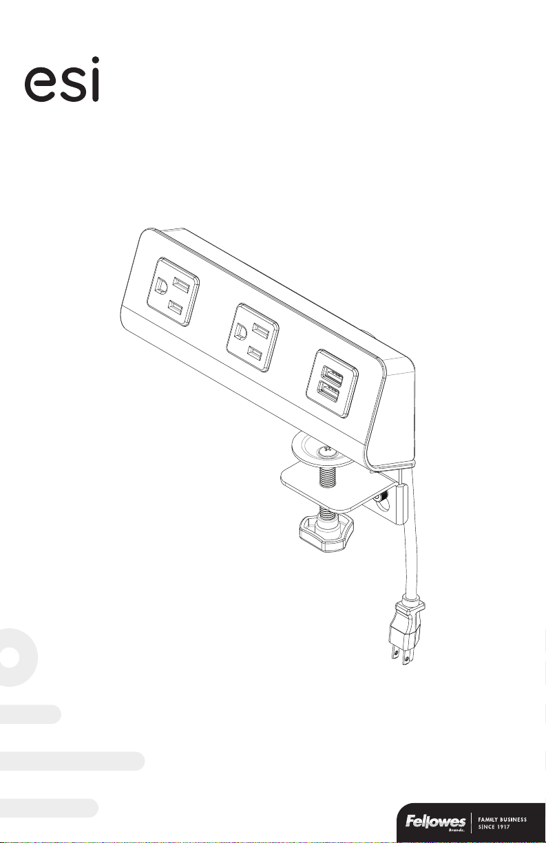
FlexCharge4
™
assembly and operation instructions
personal desktop power
Model #FCH4-DSK-WHT
Model #FCH4-DSK-BLK
Page 2
FlexCharge4 Safety instructions
Safety instructions/warning
Always read the safety instructions carefully.
• Do not install near heat sources such as radiators, heat registers stoves, or
other equipment (including amplifiers) that produce heat.
• Unplug the unit during lightning storms or when unused for extended
periods of time.
• To reduce the risk of fire or electric shock, do not expose this unit to rain or
moisture, including any drips or splashes.
• Objects filled with liquids such as vases, should never be placed on or near
the unit.
• Do not open due to risk of electric shock hazard.
• The outlet used to power the unit should be easily accessible and located
near the equipment.
• The unit is for indoor use only.
• Please refer to the marking label on the unit for input and output ratings. Do
not overload the power supply.
• DO NOT USE this product in life support applications where failure of this
unit can reasonably be expected to cause the failure of the life support
equipment or to significantly aect its safety or eectiveness is not
recommended. Do not use this equipment in the presence of a flammable
anesthetic mixture with air, oxygen or nitrous oxide.
• Failure to adhere to these instructions eectively voids the warranty.
Please review these instructions before beginning the installation. Check that all parts and tools
needed were provided with your order. Contact your supplier if any parts are missing. Do not discard the
packaging until content that the product operates to your satisfaction.
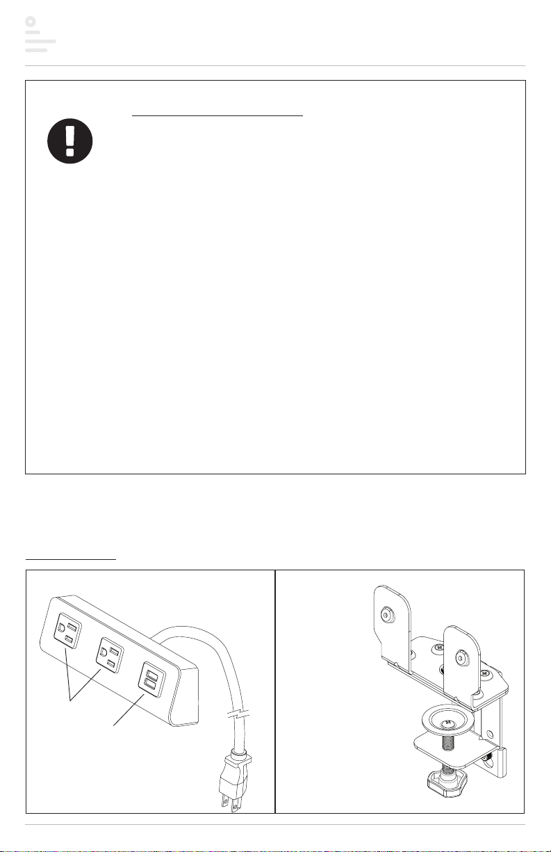
Parts provided
Power module (1) Bottom bracket (1)
power outlets
USB charging ports
Page 1
Page 3
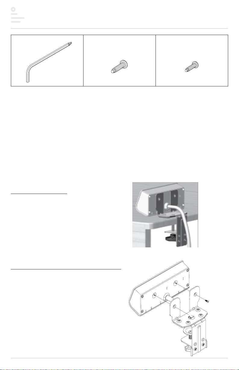
FlexCharge4 Parts and tools
M3x12 Panhead screw (2)M4 Allen key (1) M4x14 Panhead screw (4)
Caution: Hand-tighten screws only.
Additional tools required
• Phillips screwdriver
• Power drill with ⁄” drill bit (under-desk mounts only)
There are three ways to mount the FlexCharge4 power module:
• Edge Mount (page 2)
• Grommet Mount (page 3)
• Under-Desk Mount (page 5)
Choose the best mounting method based on user preference and the mounting circumstances.
Desk clamp (option 1)
With the edge mount method, the product is
clamped to the edge of the work surface.
Step #1 assemble the brackets and clamp
• Route the power cord through the opening in the top
bracket.
• Attach the top bracket to the rear of the power
module using the two M3x12 panhead screws.
Tighten securely.
Page 2
power module
M3x12
Page 4

FlexCharge4 Desk clamp
Step #2 attach bracket/clamp assembly to power module
• Position the assembly in the desired location and clamp securely to the
worksurface by tightening the triangle knob.
• Plug the power cord into an AC outlet
You are now ready to use the two AC power outlets
and two USB charging ports on the FlexCharge4.
Desk clamp (option 2)
The grommet mount method is similar to the edge mount
method, except here the assembly is clamped to the edge of a
2.3” grommet hole rather than the edge of the worksurface.
worksurface
Step #1 remove the desk clamp
• Loosen the (2) M5x8 socket cap screws
using the M4 Allen key.
— Desk clamp can be removed.
Page 3
Page 5

FlexCharge4 Desk clamp continued
Step #2 attach bracket assembly to power module
• Route the power cord through the opening in the top bracket.
• Attach the top bracket to the rear of the power module using
the two M3x12 panhead screws. Tighten securely.
power module
M3x12
2”
Step #3 clamp power module assembly to worksurface
• Re-tighten the two M5x8 screws to the bottom bracket, leaving about ⁄” exposed between the screw
heads and the bracket.
— With worksurface thicknesses between 0.9” and 2”, attach the screws to the bottom two holes.
Attach the clamp to the top two holes if the worksurface thickness is less than 1.5”.
• Insert the bottom bracket through the grommet hole.
• Attach the clamp to the bottom bracket.
— Fit the keyhole openings in the clamp over the M5x8 screw heads. Tighten the screws securely over
the narrow portion of the keyholes using the M4 Allen key.
• Clamp the assembly securely to the worksurface by tightening the triangle knob.
• Plug the power cord into an AC outlet.
0.13
exposed
M5x8
minimum hole
diameter = 2.3”.
worksurface
hook clamp
keyholes onto
screws and tighten
grommet
hole
You are now ready to use the two AC power outlets and two USB charging ports on the FlexCharge4.
Page 4
Page 6

FlexCharge4 Grommet mount
Top Bracke
Desk clamp (option 3)
With this method, the top bracket is turned upsidedown so that it can be mounted to the underside of
the worksurface with M4x14 wood screws. As with the
other methods, the power module is mounted to the
bracket using two M3x12 panhead screws.
Step #1 drill pilot holes
• Use the top bracket as a template to mark where to drill four
pilot holes.
Drill 0.5” deep pilot holes using a 0.125” drill bit.
Caution: Be careful not to not drill through the top of the worksurface.
Step #2 remove the desk clamp
• Loosen the M5x8 socket cap screws using the
M4 Allen key.
• Remove the bottom bracket by loosening the
#6-32x1/4” flathead screws using a Phillips
screwdriver
Step #3 attach bracket to underside of worksurface
• Route the power cord through the opening in the top bracket.
• Attach the bracket in the desired location (typically at the front
of the worksurface on the left or right side) using the four M4x14
wood screws. Tighten securely.
#6-32x1/4
top bracket
bottom
bracket
clamp
M5x8
top bracket
Page 5
Page 7

FlexCharge4 Additional features
Step #4 attach power module to bracket
• Route the power cord through the opening in the top
bracket.
• Attach the power module to the bracket using the two
M3x12 panhead screws. Tighten securely.
You are now ready to use the two AC power outlets and
two USB charging ports on the FlexCharge4.
Additional features
• Built-in surge protection
• Rotation AC outlet orientation designed to accomodate large plugs
• Complies with UL 962A Standard for Furniture Power Distribution Units and
meets respective spill test criteria.
M3x12
M4x14
power module
3.1A USB charging module can charge one
tablet and one smart phone at the same time.
Page 6
Page 8

evolution of motion
™
™
FlexCharge4
personal desktop power
Please contact Customer Service with any
questions or comments at 800.833.3746
or visit our website at esiergo.com
LIMITED WARRANTY
ESI warrants this product to be free from defects in manufacturing for a period of one year from the date of original purchase.
This warranty extends only to the original purchaser, and does not apply if the product has been damaged or fails to function
properly as a result of misuse, abuse, modification, alteration, or improper cleaning or maintenance. This warranty does
not apply to damage in shipment caused by carriers, damage caused during installation, normal wear and tear, or excessive
use (meaning consistent use in excess of an eight hour shift). ANY IMPLIED WARRANTIES OF MERCHANTABILITY OR FITNESS
FOR A PARTICULAR PURPOSE ARE LIMITED IN DURATION TO ONE YEAR FROM THE DATE OF ORIGINAL RETAIL PURCHASE.
ESI’s sole obligation under this warranty or any implied warranty, and the purchaser’s sole remedy, is limited to the repair
or replacement, at ESI’s option, of the product or any defec tive part. Costs (such as installation, labor fees or express
shipping) incurred due to replacement of products are not covered under warranty. IN NO EVENT SHALL FELLOWES, ITS
AFFILIATES, SUBSIDIARIES, RELATED ENTITIES OR THEIR RESPECTIVE OFFICERS, DIRECTORS, OR EMPLOYEES, BE LIABLE
FOR INCIDENTAL, CONSEQUENTIAL, PUNITIVE, EXEMPLARY, OR SPECIAL DAMAGES.
To make a warranty claim, contact ESI at 800-833-3746 or customerservice@esiergo.com. You must provide proof of
purchase, such as the original purchase order number.
The duration, terms and conditions of this warranty are valid worldwide, except where dierent limitations, restrictions or
conditions may be required by local law.
FCH4-DSK Rev F 05/2018© 2018 Fellowes, Inc.
 Loading...