

Page 1
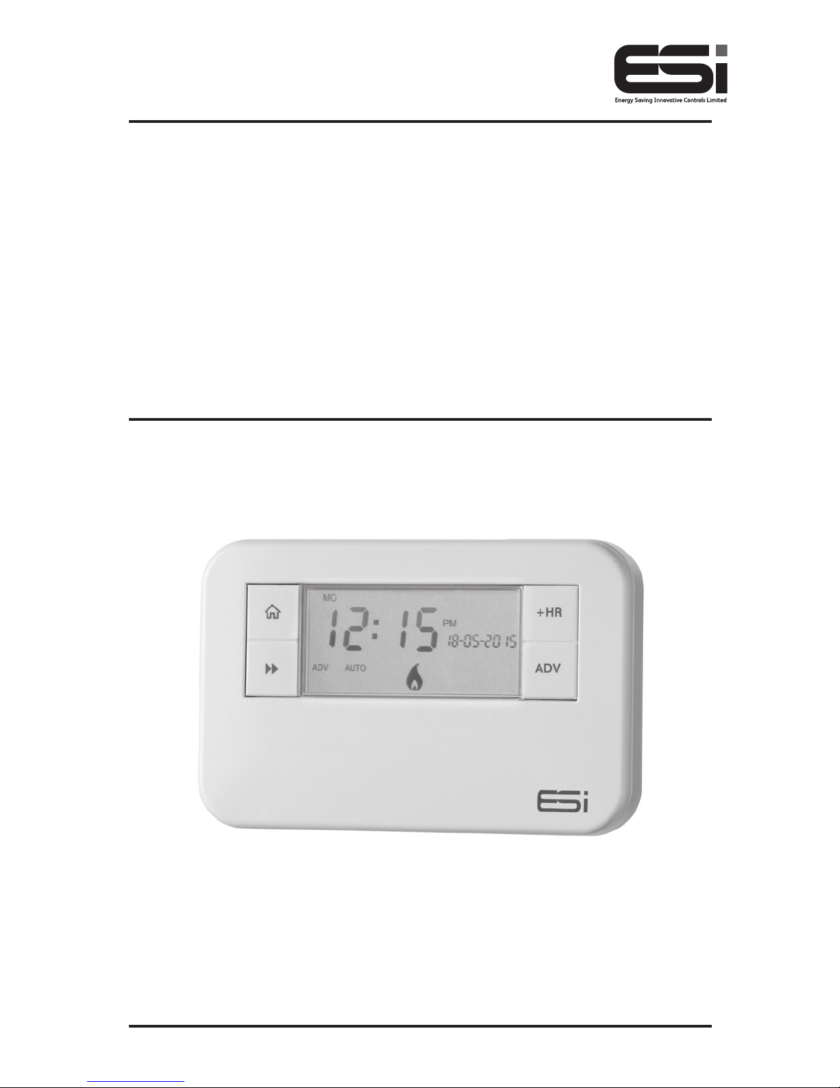
ES1247B16A
16 Amp 1 Channel Multi
Purpose Programmer
Installation Instructions
Page 2

Thank you for choosing ESi Controls.
All our products are tested in the UK so we are
confident this product will reach you in perfect
condition and give you many years of service.
However, for additional peace of mind, we
recommend you register your product online at
www.esicontrols.co.uk/warranty for your
extended warranty.
2
Page 3

3
Technical Data
Contact Rating 16(4) Amp 230VAC
Supply 230V 50/60 Hz a.c.
Switch Rating 230V AC, (4) A SPDT
Fixing
Industry Standard - Surface and Flush
Mounting
Resolution of Programs 10 Minutes
Power Consumption: 10VA Maximum
Insulation Class Double
Enclosure Protection IP30
Case Material Thermoplastic, Flame retardant
Wiring For Fixed wiring only
Temperature Rating T35
Operation Temperature 0°C to 35°C
Display: LCD Program
Clock
24Hr or 12Hr selectable with 1 minute
resolution
BST/GMT Time Change Automatic
Clock Accuracy +/- 1 Sec a day
Program Selectable Auto, On, Off, All Day or Boost
Program On/Off per day
2 On/Off or 3 On/Off Operations
selectable
Program Cycle 24 Hour, 5/2 Day or 7 Day selectable
Boost Settings 1,2 or 3 hour user selectable boost
Category Normal
Page 4

4
The unit must be installed by a suitably qualified person in
accordance with the latest IEE Wiring Regulations.
Isolate mains supply before commencing installation. Please
read all instructions before proceeding.
Ensure that the fixed wiring connections to the mains supply
is via a fuse rated at not more than 20 amps and class ‘A’
switch having a contact separation of a minimum of 3mm in
all poles. Use appropriate cable size for maximum load.
No earth connection is required as the product is double
insulated but ensure continuity of earth throughout the
system. To facilitate this, an earth park terminal is supplied on
the back plate.
If the unit is fitted to a metal surface, IT IS ESSENTIAL that
the metal be earthed. DO NOT use a surface mounting box.
Maintenance
Always isolate the mains supply before commencing any
work, servicing or maintenance on the system. And please
read all instructions before proceeding.
Arrange for an annual maintenance and inspection schedule
to be carried out by a qualified person on every part of the
heating and hot water system.
WARNING: Always isolate the AC mains supply before
installing. This product must be fitted by a competent
person, and installation must comply with the guidance
provided in the current editions of BS767 (IEE wiring
regulations) and part “P” of the building regulations.
Installation safety instructions
Page 5

5
Technical settings
Setting the Installer Settings
1. Move the slider to RUN. Hold down the
Home
button, the Copy Button and + (plus) button (under
the facia) together for 3 seconds to enter the Installer
Setting Mode.
2. The LCD display will show C0dE. Press the +/– buttons
to enter the first digit of the code. Press the Day button
to move to the next digit. Repeat this until all 4 digits
have been entered and then press the Next
button.
N.B. Only when the code entered matches either the pre-set
or master code can the landlord settings be entered. The
factory default code is 0000.
3. When the code has been entered press the Next
button and if the code has been entered correctly,
the LCD will show ProG. Press the +/– key to select the
desired program, choose between:
Prog 0: Functions as a standard 1 Channel Programmer.
Prog 1: When the ESI124716A has been set to program
1, the time switch becomes a simple to use
Electronic Boost controller with a single button
operation, offering three user-selectable boost
periods of 1 hour, 2 hour or 3 hours.
Prog 2. If program 2 is selected, then this allows the
user to boost the power as above, but also
allows the installer to set On and Off times.
Once the On/Offs have been set, all other
functions apart for the standard 1, 2, 3 hour
boost all other functions are locked.
Page 6

6
Prog 3. Program 3 allows the installer to set the On and
Off times and all other functions including the
boost, will be disabled.
4. Press the
Home button or wait for 15 seconds to
automatically confirm and return to Run Mode.
Setting the Programmer Settings
1. Move the slider to RUN. Hold down the
Home
button, the Day button and the – (minus) button
(under the facia) together for 3 seconds to enter the
Technical Setting Mode.
2. Press +/– to choose between 2 or 3 ON/OFFs per day.
3. Press the Next
button and press +/– to choose
between Protection ON/OFF. (If Protection is ON and
the system does not call for heat for one week, the
system will be turned ON for one minute each week
that the system does not call for heat).
4. Press the Next
button and press +/– to choose
between 12-hour clock or 24-hour clock.
5. Press the Next
button and press +/– to choose
between Std (standard time with the changeover at
2.50am) or ECON (economy time with the changeover
at 00.00am, midnight).
Programme / Functions Prog 0 Prog 1 Prog2 Prog 3
Set Time / Date Yes Yes Yes Yes
Set Programme Times Yes No No No
Boost 1/2/3 Hour Yes Ye s Yes No
Advance Yes No No No
Holiday Yes Yes Yes Yes
Run Programme Yes No Yes Yes
Change Auto/On / Off / Run Yes No No No
Page 7

7
6. Press the Home button or wait for 15 seconds to
automatically confirm and return to Run Mode.
Setting the Landlord Service Interval
1. Switch the slider to RUN.
2. Press
Home, Copy and the + buttons together to
enter the landlord settings. A numeric password will be
required to enter these settings.
3. The LCD display will show C0dE. Press the +/– buttons
to enter the first digit of the code. Press the Day button
to move to the next digit. Repeat this until all 4 digits
have been entered and then press the Next
button.
N.B. Only when the code entered matches either the pre-set
or master code can the landlord settings be entered. The
factory default code is 0000.
4. The LCD display will show ProG. Press the Next
button and the LCD will show En. Press the +/– buttons
to turn the landlord functions on/off.
5. If landlord functions are turned on, press the Next
button and the LCD display will show SHO. Select on
and the LCD will display ArEA and this will allow a
contact number to be entered. Press the +/– buttons
to set the area code for the maintenance telephone
number. Press the Day button to move to the next
digit. Repeat this until all digits have been entered and
then press the Next
button.
6. The LCD display will show tELE. Press the +/– buttons
to set the maintenance telephone number. Press the
Day button to move to the next digit. Repeat this until
all digits have been entered and then press the
Next
button.
Page 8

8
7. The LCD display will show duE. Press the +/– buttons
to set the due date (from 1 - 450 days).
8. Press the Next
button and the LCD display will show
ALAr. Press the +/– buttons to set the reminder (from
1 - 31 days). This will then remind the user when the
annual service is due by alternating between displaying
SER and the maintenance telephone number in the
LCD screen according to these settings.
9. Press the Next
button and the LCD display will show
tYPE. Press the +/– buttons to choose between: -
0: Reminds the user when the annual service is due
by alternating between displaying SER and the
maintenance telephone number in the screen
according to installer set settings.
1: Reminds the user when the annual service is due
by alternating between displaying SER and the
maintenance telephone number in the screen
according to installer set settings and only allows the
system to run in manual operation for
60 minutes.
2: Reminds the user when the annual service is due
by alternating between displaying SER and the
maintenance telephone number in the screen
according to installer set settings and does not allow
the system to run (permanently OFF).
10. Press the Next
button and the LCD display will show
nE. Here a new installer code can be entered. Press
+/– to set the first digit, then press the Day button.
Repeat this for all four digits. Press the Next
button
to confirm the changes and the LCD display will show
SET to confirm.
Page 9

9
11. Press the Home button or wait for 15 seconds to
automatically confirm and return to Run Mode.
Fitting the Back Plate
1. Position the wall-plate (terminals along top edge) with
60mm (min) clearance to its right, 25mm (min) above,
90mm (min) below. Ensure that the supporting surface
will fully cover the back of the programmer.
2. Offer the back plate to the wall in the position where the
programmer is to be mounted, remembering that the
back plate fits to the left side of the programmer. Mark
the fixing positions through the slots in the back plate,
drill and plug wall, then secure back plate in position.
3. All necessary electrical connections should now
be made. Ensure that the wiring to the wall-plate
terminals leads directly away from the terminals and
is completely enclosed within the wall-plate aperture.
Wire ends must be stripped and screwed to the
terminals so that minimal bare wire is showing.
To enter a New Installer Code
1. Move the slider to RUN.
2. Press Home, Copy and the + buttons together to enter
the landlord settings. A numeric password will be
required to enter these settings.
3. The LCD display will show C0dE. Press the +/– buttons
to enter the first digit of the code. Press the Day button
to move to the next digit. Repeat this until all 4 digits
have been entered and then press the Next
button.
N.B. Only when the code entered matches either the pre-set
or master code can the landlord settings be entered.
The factory default code is 0000.
Page 10

10
4. The LCD display will show ProG. Continue to press the
Next
button until the LCD will show NE 0000. Press
the Day button and the first digit will flash, then use
the +/– buttons to choose a new code using the Day
button to move between digits.
5. When the desired code is entered correctly, press
Next
button to confirm changes.
6. Press
Home button to exit the menu.
Wiring diagram
Commissioning
Switch on the mains supply. Referring to pages 4, 8, 9 and 13
of the User Instructions:
1. Use the buttons to ensure correct product functionality.
2. Set timing and programme details in accordance with
customer requirements.
3. Normally the unit will be left with channel in ‘Auto’ mode.
4. Set backlight either permanently ON or OFF in
accordance with customer requirements.
Page 11

11
WARNING: Interference with sealed parts renders the
guarantee void.
In the interests of continuous product improvement we reserve
the right to alter designs, specifications and materials without
prior notice and cannot accept liability for errors.
We are continuously developing our products to
bring you the very latest in energy saving technology
and simplicity. However, should you have any questions
setting up your controls please email us at
sales@esicontrols.co.uk or for technical queries call
us on our dedicated technical helpline 07539 117468.
Page 12

Version 6.10.2
© ESi Controls Limited 2017
 Loading...