

ESI Enmo 2NM-C48-SLV, Enmo 2NM-C48-BLK, Enmo 2NM-C48-WHT Assembly And Operation Instructions Manual
Page 1
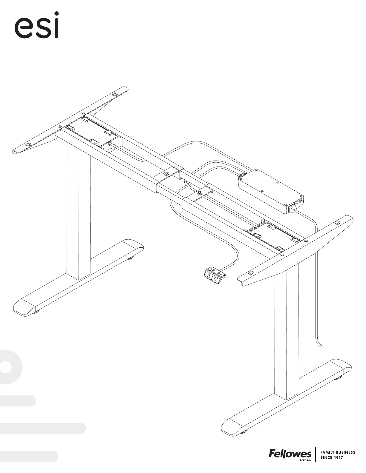
Enmo
™
Assembly and operation instructions
Electric height adjustable table base
Model# 2NM-C48-SLV
Model# 2NM-C48-BLK
Model# 2NM-C48-WHT
Page 2
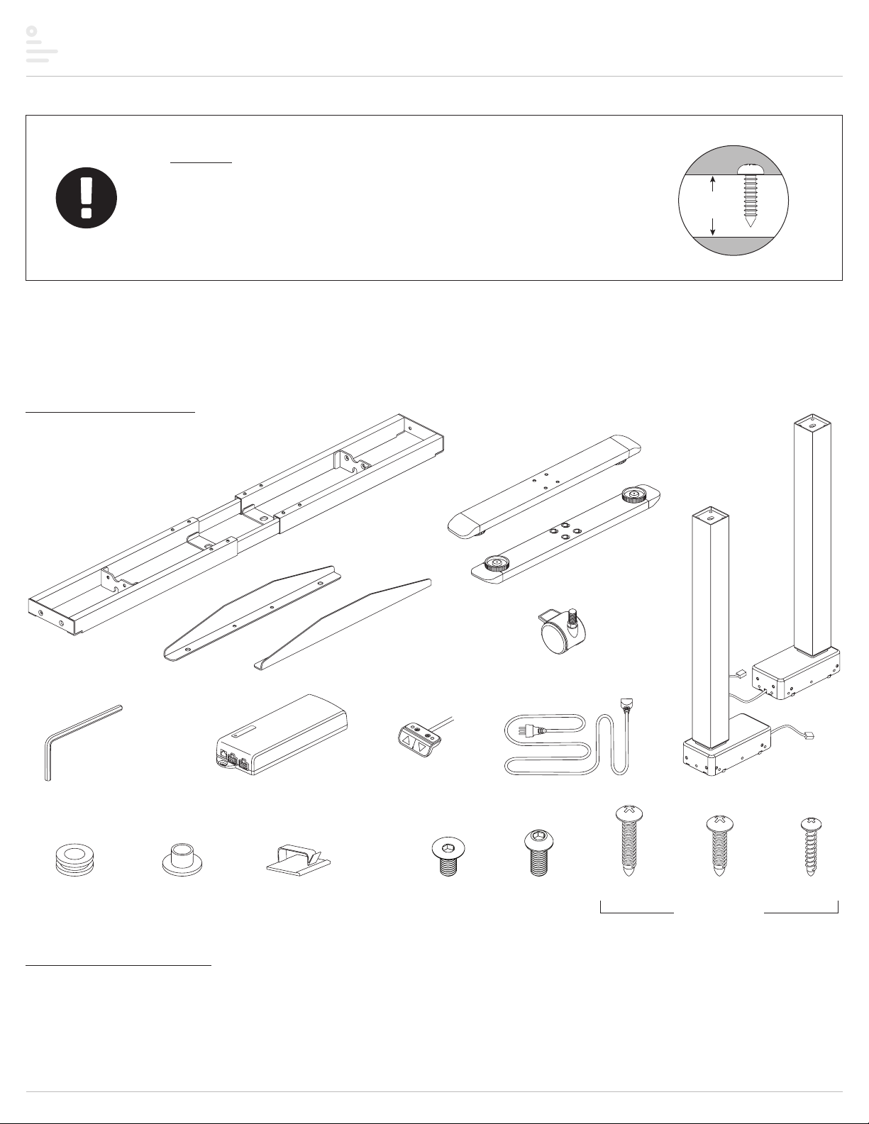
Enmo Components and tools
table
thickness
Caution
• Hand tighten all hex-head screws. Use power drill on self-tapping screws
only.
• Always check that screws used to attach components to the worksurface
are not too long for the thickness of the table.
Please review these instructions before beginning the installation. Use the illustrations below to check that all components needed for your installation
were provided with your order. Do not discard the packaging until the product works to your satisfaction.
Components and tools
4mm Allen key (1)
frame (1)
control
unit (1)
top supports (2)
handset (1)
screws:
feet (2)
legs with
motor (2)
optional caster kit
(includes 4 casters)
power cord (1)
rubber cushions (7)
plastic pads (7)
Additional tools required
• Power drill with Phillips #1 and #2 bits
adhesive cable ties (6)
Page 2
M6x14 (9)M6x12 (13)
ST4.8x25 (7)
ST4.8x19 (3)
ST = self-tapping
ST3.5x19 (3)
Page 3
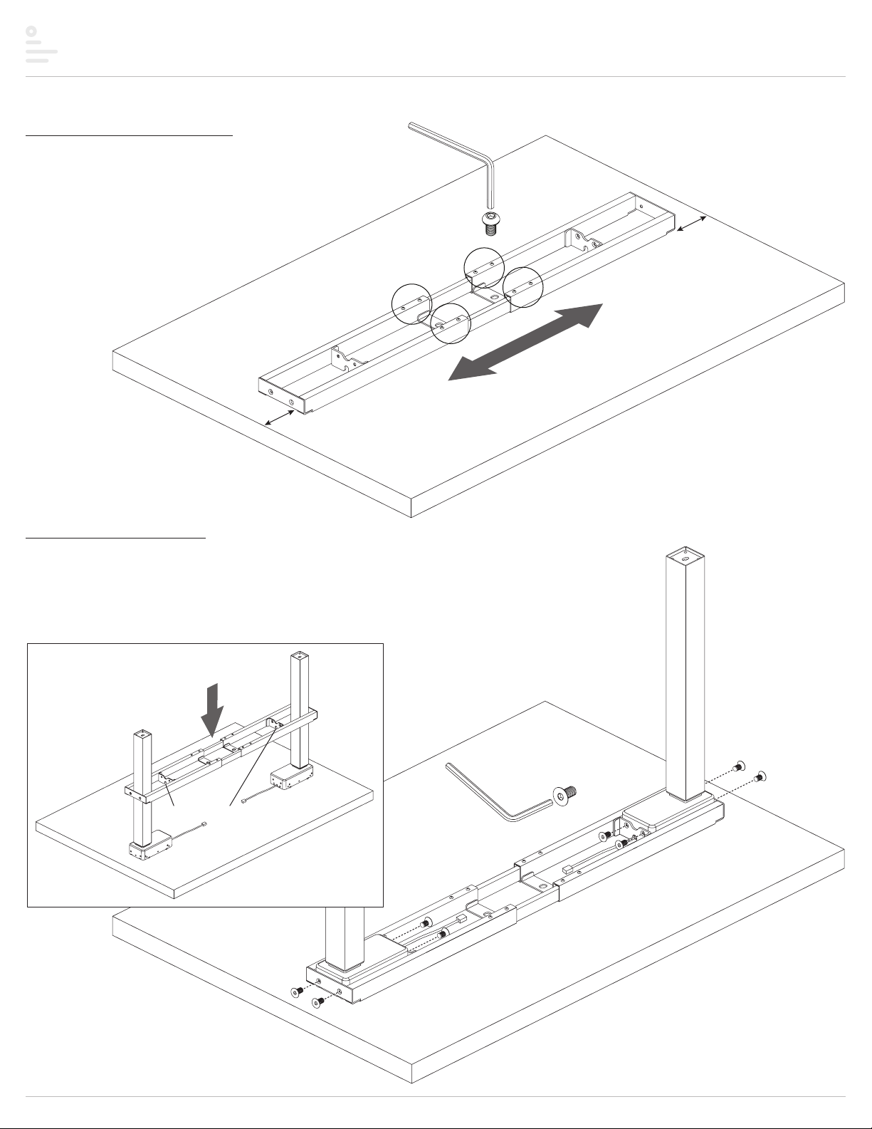
Enmo Assembly
Step #1: adjust frame width
• Place the worksurface facing down on a soft, clean surface.
• Center the frame front to back on the worksurface.
• Adjust the width of the frame.
— Use the 4mm Allen key to loosen all eight pre-installed M6x10
screws in the cross channels.
— Expand the frame so that its ends are 2" to 3" from
the edges of the table.
— Tighten the M6x10 set screws to hold
the width.
2" to 3"
M6x10
(pre-installed)
4mm Allen key
2" to 3"
Step #2: attach the legs
• Place the legs next to the frame, adjacent to their future location.
• Lower the frame over the legs so that the base of the legs fit in the opening between the end of the frame
and the first cross support.
— Fit the openings in the cross supports over the motor cables.
• Attach each leg to the frame with four M6x12 screws per leg, as shown.
lower frame over legs
openings fit over motor cables
4mm
Allen key
M6x12
Page 3
Page 4
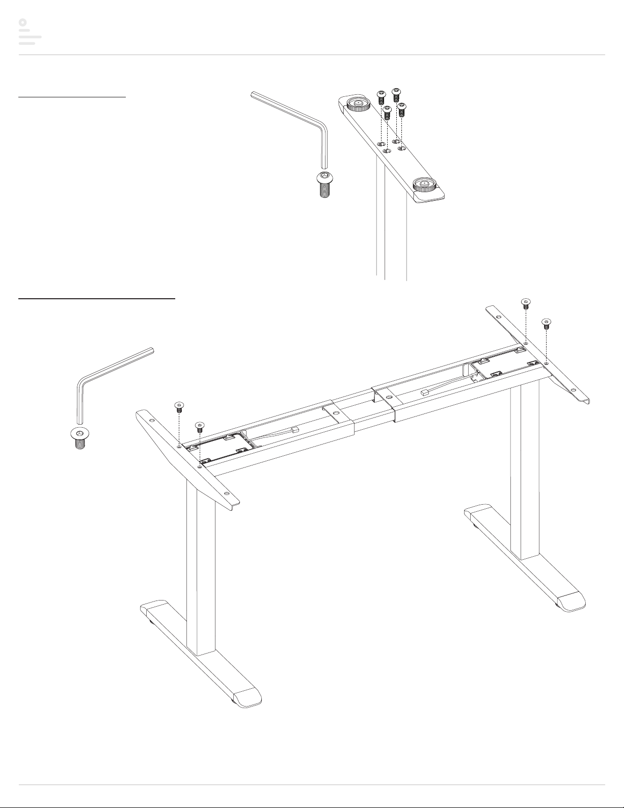
Enmo Assembly
Step #3: attach feet
• Attach a foot to each leg with four M6x14 screws per foot.
4mm Allen key
M6x14
Step #4: attach top supports
• Turn the frame upright.
• Attach the top supports to the end of the frame with two M6x12 screws per support.
4mm Allen key
M6x12
top
support
top
support
Page 4
Page 5

Enmo Assembly
Step #5: install rubber cushions and plastic pads
• Insert rubber cushions into the holes on the ends of the top supports and center of the two crossbeams.
— When properly inserted, the cushions will be centered vertically.
• Press-fit a plastic pad into the underside of each cushion.
rubber cushion
plastic pad
Page 5
Page 6

Enmo Assembly
Step #6: secure frame to worksurface
• Turn the assembly over and place the frame and top supports onto the worksurface.
— Center the assembly on the worksurface, front to back and side to side.
• Using a power drill and #2 Phillips bit, secure the frame to the worksurface with six ST4.8x25 self-tapping screws.
— Screw through the six plastic pads/rubber cushions.
ST4.8x25
Page 6
Page 7

Enmo Assembly
Step #7:
• Remove the two glides attached to each foot.
— Unscrew the glides to remove them.
• Attach two casters to each foot.
— Screw in the casters by turning the stem nut on each caster clockwise.
— Secure the casters in position by tightening the nuts using a 12mm wrench.
if optional caster kit was ordered,
install casters
unscrew glide
screw in
caster
remove
glide
stem nut
Step #8: attach control unit and handset
• Attach the control unit to the worksurface with two ST4.8x19 self-tapping screws.
— Position the control unit on the rear side of the frame’s cross channels in a location where 1) its ports can be reached by the cables from the legs and handset,
and 2) the power cord will be convenient to an outlet or power strip.
• Attach the handset to the worksurface with two ST3.5x19 self-tapping screws.
— Position the handset flush with the front edge of the worksurface, on the left or right side according to user preference. Be sure the cable can reach its port on
the control unit.
tighten with
12mm wrench
control unit
ST4.8x19
handset
ST3.5x19
Page 7
Page 8

Enmo Assembly
cable
tie
Step #9: connect cables and cords
• Connect the cables from the handset and each of the leg motors to their ports on the control unit.
• Plug the female end of the power cord into the control unit.
• Use the adhesive cable ties to organize the cables and power cord.
— Important: The cables and cord must not dangle under the table where they may present a hazard to the user or may accidentally be pulled from their connections.
handset
cable
motor cables
from legs
control
unit
power cord
control
unit
handset
Page 8
Page 9

Enmo Assembly and operation
Step #10: initialize table and test operation
• Plug the power cord into an outlet or power strip.
• Initialize the table by pressing both the UP s and DOWN t buttons on the handset at the same time.
— Continue to press both buttons until you hear a soft beep sound.
— The table will move to its lowest position and then “bump up” slightly.
• Press the UP s and DOWN t buttons individually to test operation.
— End your test with the legs fully lowered.
— Unplug the power cord.
press both to
initialize table
NOTICE: The table must be re-initialized when power is restored.
• If there are problems with operation, check that all cable and cord connections are secure.
— Re-initialize the table. Be sure to press both buttons until you hear the beep sound. Be sure the table moves to its lowest position and then “bumps up” slightly.
— If problems continue, call ESI Customer Service at 800.833.3746.
Step #11: complete the installation
• With the assistance of a helper, turn the table upright and place it in its final position.
— Important: There must be an inch of clearance on all sides of the worksurface (and other moving parts) to ensure free, unobstructed movement.
• If necessary, adjust the leveling glides on the feet to level the worksurface. Each glide can be adjusted up to ½".
• Plug the power cord into an AC outlet.
• Re-initialize the table. See Step #9 above.
NOTICE: Whenever the unit is unplugged or the power is cut, the table must be re-initialized.
Page 9
Page 10

Enmo Troubleshooting
Troubleshooting Guide
Problem Possible Cause Solution
The table stops suddenly during
operation and the control unit beeps
once. The control unit beeps when
the UP s or DOWN t button is
pressed.
The table stops suddenly and the
control unit beeps slowly five times.
The table stops suddenly and the
control unit beeps rapidly five times.
During operation, the table stops
moving and reverses direction
40 mm.
When in its lowest position, the table
will not move when the UP s or
DOWN t button is pressed.
Overuse — operation of the table
has exceeded the duty cycle
(continuous operation time).
The electrical current needed has
exceeded the amount provided.
There is no signal to the control unit
or the legs are not level.
The anti-collision feature has
engaged.
Incomplete re-initialization — there
was no beep and no “bump up” from
the lowest position.
Wait 20 minutes to resume normal use. After 20 minutes, the control unit will
reset and operation can continue.
1) Check that the top load on the table is balanced from side to side.
2) Check that the top load is less than the rated weight.
3) Unplug the power cord. Press either button on the handset. Then plug the
power cord back in. Re-initialize the table by pressing and holding the
UP s and DOWN t buttons at the same time until the control unit beeps
and the table moves to its lowest position, then “bumps up” slightly.
1) Unplug and reconnect all cords and cables at the control unit, ensuring that
all connections are fully engaged.
2) Check that all cables are undamaged.
3) Check that the circuit breaker has not tripped.
4) Re-initialize the table by pressing and holding the UP s and DOWN t
buttons at the same time until the table moves to its lowest position, then
“bumps up” slightly.
Check that there is adequate space (minimum 1") around all parts of the table,
including moving leg components. Remove any obstacles.
Re-initialize the table by pressing and holding the UP s and DOWN t buttons
at the same time until the control unit beeps and the table moves to its lowest
position, then “bumps up” slightly.
The table does not move and the
control unit does not emit any
sounds.
After installation, the table wobbles
or vibrates.
After installation or after a long
time without use, the table columns
vibrate or make noise.
There is no power to the table. 1) Check that the power cord, all motor cables, and control unit cables are fully
plugged in.
2) Check that all cables are undamaged.
3) Check that the circuit breaker has not tripped.
4) Unplug the power cord. Press either button on the handset. Then plug the
power cord back in. Re-initialize the table by pressing and holding the
UP s and DOWN t buttons at the same time until the control unit beeps
and the table moves to its lowest position, then “bumps up” slightly..
The screws were not fully tightened. 1) Check that the fasteners securing the feet to the legs and the legs to the
frame are fully tightened.
2) Check that all fasteners securing the frame to the table are fully tightened.
The internal leg components need to
be actuated.
With a normal load on the table, fully raise and fully lower the table through five
to ten cycles. The vibration or noise should disappear.
Page 10
Page 11

Page 12

™
Enmo
Electric height adjustable table base
Please contact Customer Service with any questions or
comments at 800.833.3746 or visit our website at esiergo.com
LIMITED WARRANTY
ESI warrants this product to be free from defec ts in manufacturing for a period of 15 years on structural parts and 7 years on electrical parts from the date of original purchase. This warranty
extends only to the original purchaser, and does not apply if the product has been damaged or fails to function properly as a result of misuse, abuse, modification, alteration, or improper cleaning or
maintenance. This warranty does not apply to damage in shipment caused by carriers, damage caused during installation, normal wear and tear, or excessive use (meaning consistent use in excess
of an eight hour shif t). ANY IMPLIED WARRANTIES OF MERCHANTABILITY OR FITNESS FOR A PARTICULAR PURPOSE ARE LIMITED IN DURATION TO ONE YEAR FROM THE DATE OF ORIGINAL RETAIL
PURCHASE. ESI’s sole obligation under this warrant y or any implied warranty, and the purchaser’s sole remedy, is limited to the repair or replacement, at ESI’s option, of the product or any defective
part. Costs (such as installation, labor fees or express shipping) incurred due to replacement of products are not covered under warranty. IN NO EVENT SHALL FELLOWES, ITS AFFILIATES, SUBSIDIARIES,
RELATED ENTITIES OR THEIR RESPECTIVE OFFICERS, DIRECTORS, OR EMPLOYEES, BE LIABLE FOR INCIDENTAL, CONSEQUENTIAL, PUNITIVE, E XEMPL ARY, OR SPECIAL DAMAGES.
To make a warranty claim, contact ESI at 800-833-3746 or customerservice@esiergo.com. You must provide proof of purchase, such as the original purchase order number.
The duration, terms and conditions of this warranty are valid worldwide, except where dierent limitations, restrictions or conditions may be required by local law.
2NM Rev A 9/2019© 2019 Fellowes, Inc.
 Loading...