

ESI ALL-FLEX FLEX3-SLV-V1, ALL-FLEX FLEX3-BLK-V1, ALL-FLEX FLEX3-WHT-V1 Assembly And Operation Manual
Page 1
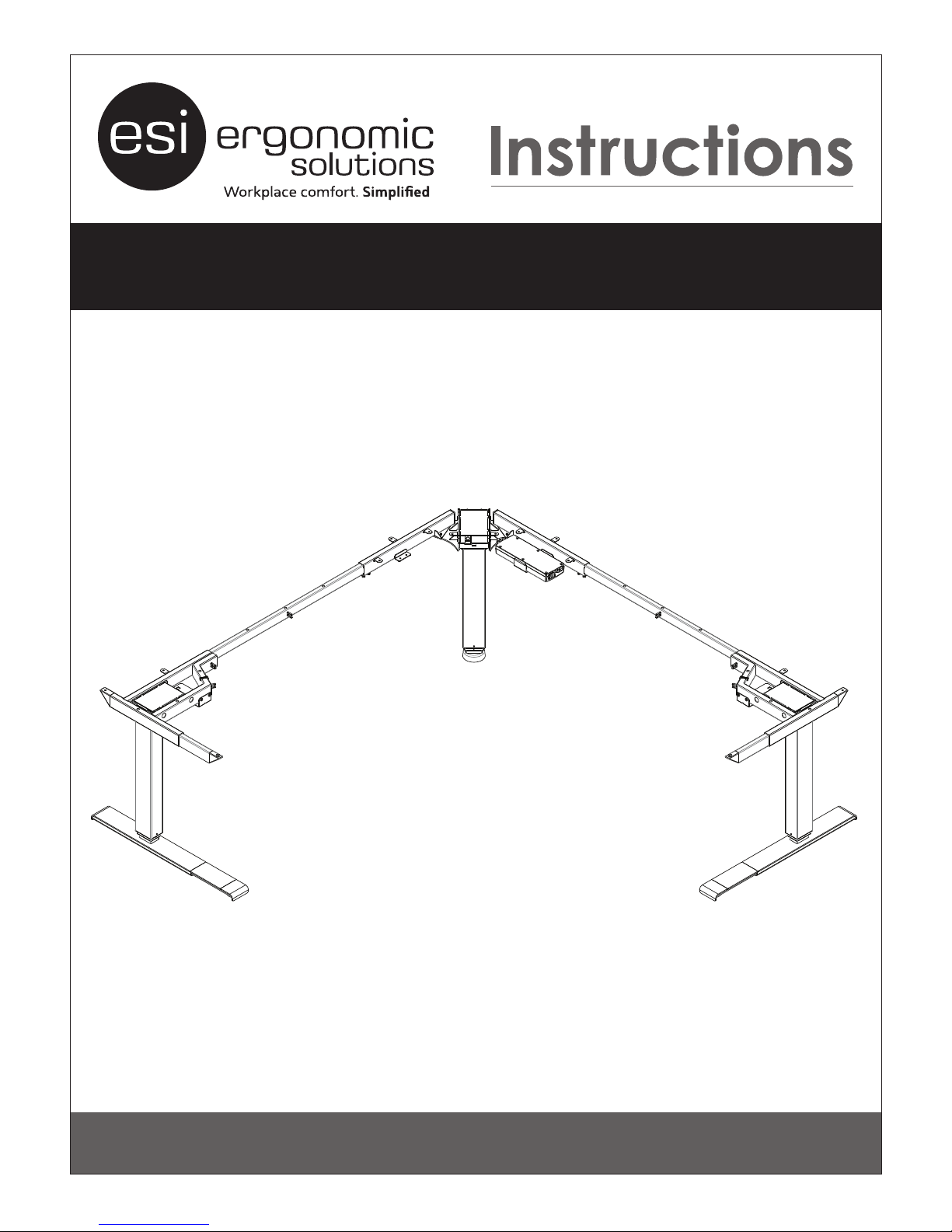
ASSEMBLY AND OPERATION
ALL-FLEX
3 LEG ELECTRIC TABLE BASE
FLEX3-V1 Rev B 6/17
™
Model FLEX3-SLV-V1
Model FLEX3-BLK-V1
Model FLEX3-WHT-V1
Page 2
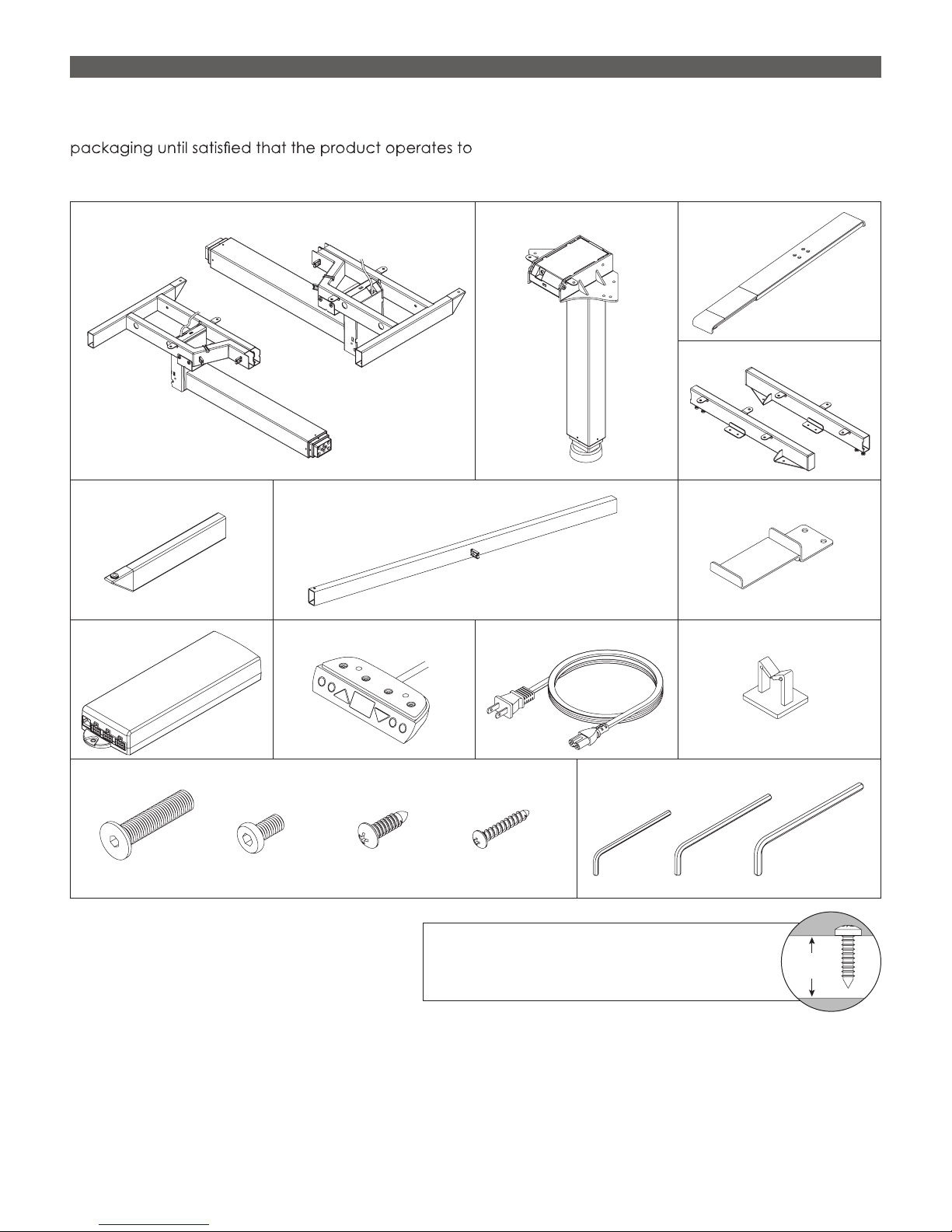
ALL-FLEX™ 3 LEG ELECTRIC TABLE BASE PARTS AND TOOLS
Work
Surface
PLEASE REVIEW these instructions before beginning the assembly procedures. Check that all the parts shown
below were provided with your order. Contact your supplier if any materials are missing. Do not discard the
your satisfaction.
PARTS AND TOOLS PROVIDED
Leg Hinged to Frame (2)
Center Leg (1)
Adjustable Feet (2)
Fasteners
Left
Right
Cross Channel (2)Side Leg Top Support (2) Control Unit Bracket (1)
Digital Keypad (1)Control Unit (1) Cable Clip (4)Power Cable (1)
Allen Keys (1 each))
Center Leg Top Support (2)
Right
Left
M6x15 (14)M10x45 (8)
NOTE: This install requires a power tool or
cordless drill. Except for the hex head
screws, which is not a hand tool install.
ADDITIONAL TOOLS REQUIRED
•
#2 Phillips drill bit
• Power Driver
2
M5x18 (18) M4x23 (2)
CAUTION: Always check that screws used to
attach components to the work surface are
not too long for the thickness of the surface.
3mm 5mm4mm
Page 3
ASSEMBLY ALL-FLEX™ 3 LEG ELECTRIC TABLE BASE
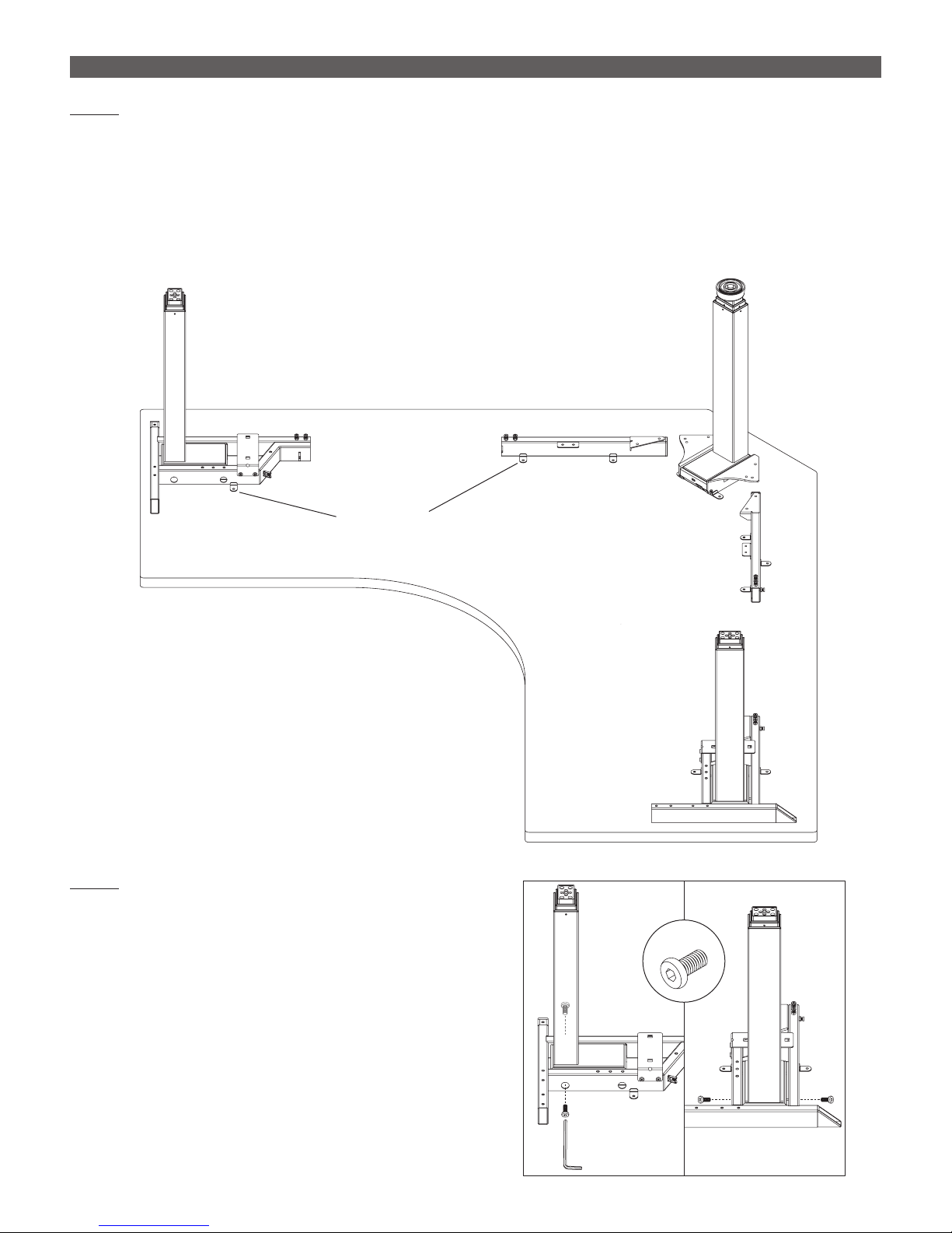
STEP 1
With the work surface facing down on a soft, clean surface, arrange the leg columns and center leg top
supports as shown.
• Unfold the hinged side legs and place them motor-side down at the ends of the work surface.
• Place the center leg motor side down near the 90° or 120° angle of the table.
• The mounting tabs on the leg columns and top supports must be face down so that they are against the
work surface.
Leg Column
with Frame
(Right)
Mounting Tabs
Center Leg
Top Support
(Right)
Center Leg
Center Leg
Top Support
(Left)
Leg Column
with Frame
(Left)
STEP 2
Lock the side leg columns in the upright position.
• Use the 4mm Allen key to install M6x15 hex head
screws into the frame and motor.
M6x15
4mm
Allen Key
3
Page 4
ALL-FLEX™ 3 LEG ELECTRIC TABLE BASE ASSEMBLY
90°
120°
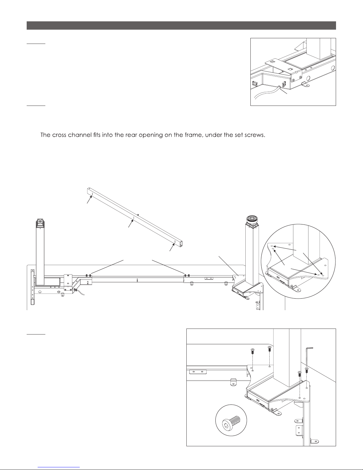
STEP 3
Route the side column motor cables under the notch on the angled
portion of each frame.
Route Cable
STEP 4
Install the cross channels.
• Insert each cross channel into the frame and center leg top support.
—
• Slide the top supports under the center leg brackets. Align the holes on the top supports with the 90° or
120° holes in the brackets. See the illustration below.
• Position each cross channel so that its center line is centered between the frame and the top support.
• The MAX lines must not extend beyond the frame and top support.
Under Notch
Cross Channel
MAX
Frame Top Support
Rear
Center Line
MAX
Set Screws
Cross Channel
STEP 5
Attach the top supports to the center leg brackets.
• Use the 4mm Allen key and four M6x15 hex head
screws.
• Use the inner hole on the bracket for 90° tables
and the outer hole for 120° tables.
Center Leg
Bracket
Top Support
4mm
Allen
Key
4
M6x15
Top
Support
Page 5

ASSEMBLY ALL-FLEX™ 3 LEG ELECTRIC TABLE BASE
3mm
Allen Key
Set
Screws
Store
Adjustment
Plates
STEP 6
Attach the two-piece side top supports. One piece is attached to the frame; the other piece is separate.
• Insert the separate piece of the top support into the top support attached to the frame.
• Align the holes on the inserted piece with the rear set of two holes on the integral top support if the table
depth is less than 30" (76cm). Align the holes with the front set if the table depth is 30" or more.
4mm
Allen Key
Two-Piece
Top Channel
Use Rear Set of Holes
STEP 7
Change the length of the adjustable feet, if necessary.
• The length of the feet may be either 22" (55.9cm) or 28"
(71.2cm). The feet are shipped in the 28" length. They
should be changed to the shorter length if the work
surface depth is less than 28".
• To change the length to 22":
A. Remove the two plastic Phillips screws holding
the adjustment plate in place.
B. Use the 5mm Allen key to remove the four hex
head screws.
C. Use the 3mm Allen key to loosen the two set
screws.
D. Slide the feet to the 22" length. Reinstall the four
hex head screws and tighten the set screws.
• Store unused adjustment plates in the brackets
attached to the frame, securing them with the two
plastic Phillips screws.
24" Table
Adjustable
A
Allen Key
30" Table
Use Front Set of Holes
28"
22"
Length
C
B
5mm
D
5
Page 6

ALL-FLEX™ 3 LEG ELECTRIC TABLE BASE ASSEMBLY
STEP 8
Attach a foot to each of the legs.
• Use four M10x45 screws per foot.
• Tighten the screws with an 5mm Allen key.
5mm Allen Key
M10x45
STEP 9
Adjust the position of the frame before attaching it to the work surface.
• Align the rear of the feet with the rear of the table.
• Center the center leg on the 90° or 120° angle.
• Check that the top supports on each side are approximately 1" (25mm) from the ends of the table.
• The rear of the feet should align with the rear of the table. With that alignment, the center leg top
supports will be 6½" from the rear of the table.
• Check that each cross channel’s center line is centered between the frame and top support, and that
the MAX lines do not extend beyond the frame and top support.
6½"
Align Rear of Feet
with Rear of Table
90°
1" 1"
1"
6½"
120°
6
Page 7

ASSEMBLY ALL-FLEX™ 3 LEG ELECTRIC TABLE BASE
STEP 10
Once the frame is in its nal position, attach it to the work surface using the M5x18 screws (16 total required).
• Attach the screws through the mounting tabs on the frame, center leg column, and center leg top
supports, as well as the holes at the ends of the side column top supports.
• Use a power drill with #2 Phillips bit. This is not a hand tool install.
• After attaching the frame, tighten all 12 set screws, as shown below.
M5x18
Tighten All 12
Set Screws
STEP 11
Attach the control unit bracket to one of the center
leg top suports.
• Secure the control unit bracket to the frame using
two M6x15 screws and the 4mm Allen key.
• The bracket may be attached on either side of
the center column. (Note that the digital keypad
will be attached on the same side.)
M6x15
4mm Allen Key
Control Unit
Bracket
7
Page 8

ALL-FLEX™ 3 LEG ELECTRIC TABLE BASE ASSEMBLY
Cables
STEP 12
Attach the control unit to the work surface.
• Slide the control unit under the bracket and
attach it using M5x18 wood screws. The motor
cable and keypad ports should face away from
the center column.
• Allow at least 2¼” (57mm) between the back of
the control unit and the center column assembly
to allow room for power cord attachment.
STEP 13
Attach the digital keypad flush with the front edge of
the work surface.
• Use the two M4x23 wood screws.
• Attach the keypad on the same side as
the control unit.
M5x18
Control Unit
M4x23
STEP 14
Make connections to the control unit.
• Connect the cable from the digital keypad.
• Connect the motor cables from the three motors.
• Connect the power cord to the control unit.
• Plug the power cord into an AC outlet.
CAUTION: Do not operate the table until after
“zero setting” the system. See the following step.
Digital Keypad
flush with the work
surface edge
Digital
Keypad
Cable
Motor
Power
Cable
Control
Unit
8
Page 9

ASSEMBLY ALL-FLEX™ 3 LEG ELECTRIC TABLE BASE
Press and Hold Both Buttons
STEP 15
“Zero set” the system before testing operation. (Note that with the table and keypad will be upside-down,
the UP ▲ and DOWN ▼ buttons face their opposite directions.)
• Press and hold the UP ▲ and DOWN ▼ buttons at
the same time. Continue to hold the buttons. The
legs will retract until they reach their bottom point.
• Release the buttons once the system beeps. If it
Digital Keypad
does not beep, continue to hold the buttons for
Work Surface
3 seconds after the legs reach the lowest point. The
system is now “zero set.”
• Press the UP ▲ or DOWN ▼ buttons to test operation. End your test with the legs lowered and unplug the
power cord.
• If there are problems with operation, check that all cable and cord connections are secure. If problems
continue, call ESI Customer Service.
STEP 16
Use the pre-installed cable clips plus the additional clips provided, to secure the cables in position.
• Cables must not interfere with table operation.
• Cables must not interfere with the user.
Pre-Installed
Cable Clip
Cable Clip
9
Page 10

ALL-FLEX™ 3 LEG ELECTRIC TABLE BASE ASSEMBLY
STEP 17
With the assistance of a helper, turn the table upright and place it in its nal position.
IMPORTANT: There must be 1" (25mm) of clearance on all sides of the work surface (and other moving parts)
to ensure free, unobstructed movement.
• Adjust the leveling glides on the feet to level the work surface, if necessary.
• Plug the power cord into an AC outlet.
• See the following page for operating procedures.
10
Page 11

OPERATION ALL-FLEX™ 3 LEG ELECTRIC TABLE BASE
Memory
Table
UP
Memory
DOWN
Buttons
Button
Height
Button
Buttons
CAUTION: The “zero setting” procedure
must be completed before operating the
table. See Step 15 on page 9.
GENERAL OPERATION
Move the table up or down by pressing UP s or DOWN t until
the work surface reaches the desired height.
The table will continue to move up or down until you release the
button or until the maximum or minimum height is reached.
IMPORTANT: Be sure there are no obstructions to table
movement along its full range of travel.
SETTING A MEMORY POSITION
The memory buttons allow you to save up to four specic
positions of the work surface. To set a memory position:
• Adjust the work surface to the position you want to save. (The
display on the control pad shows the work surface height.)
• Press the UP s button and one of the memory buttons at the
same time for 3 to 5 seconds.
Table movement stops when you
release the UP s or DOWN t button.
Example: Press the UP s button and
memory button number 3 at the
same time for 3 to 5 seconds. The
display will ash “P3” indicating that
the current table position has been
saved in memory.
• The display will ash “P” and the number of the memory
button.
• Repeat for the other memory buttons, if desired.
MOVING TO A MEMORY POSITION
• Press and hold the desired memory button.
• The work surface will move to the preset position.
Continue to press the memory button
until table movement stops.
11
Page 12

800.833.3746 esiergo.com
© 2017 ESI Ergonomic Solutions. All rights reserved. FLEX3-V1 Rev B 6/17
 Loading...