

Page 1
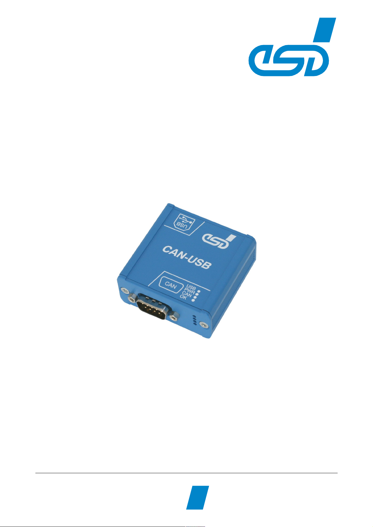
CAN-USB/2
USB 2.0-CAN-Interface
Hardware Manual
to Product C.2066.xx
CAN-USB/2
Hardware Manual • Doc. No.: C.2066.21 / Rev. 1.4
Page 1 of 25
esd electronic system design gmbh
Vahrenwalder Str. 207 • 30165 Hannover • Germany
http://www.esd.eu
Phone: +49 (0) 511 3 72 98-0 • Fax: +49 (0) 511 3 72 98-68
Page 2

N O T E
The information in this document has been carefully checked and is believed to be entirely reliable.
esd makes no warranty of any kind with regard to the material in this document, and assumes no
responsibility for any errors that may appear in this document. In particular descriptions and
technical data specified in this document may not be constituted to be guaranteed product features
in any legal sense.
esd reserves the right to make changes without notice to this, or any of its products, to improve
reliability, performance or design.
All rights to this documentation are reserved by esd. Distribution to third parties, and reproduction
of this document in any form, whole or in part, are subject to esd's written approval.
© 2013 esd electronic system design gmbh, Hannover
esd electronic system design gmbh
Vahrenwalder Str. 207
30165 Hannover
Germany
Trademark Notices
CANopen® and CiA® are registered community trademarks of CAN in Automation e.V.
Linux® is the registered trademark of Linus Torvalds in the United States and/or other countries.
Windows is a registered trademark of Microsoft Corporation in the United States and other countries.
All other trademarks, product names, company names or company logos used in this manual are reserved by their
respective owners.
Page 2 of 25
Hardware Manual • Doc. No.: C.2066.21 / Rev. 1.4
CAN-USB/2
Page 3
Document file:
I:\Texte\Doku\MANUALS\CAN\CAN-USB-2\Englisch\CAN-USB2_Hardware_en_14.odt
Date of print: 2013-03-06
Document type
number:
DOC0800
PCB version: CAN-USB/2 Rev. 1.2
Document History
The changes in the document listed below affect changes in the hardware as well as changes in
the description of the facts, only.
Revision Chapter Changes versus previous version Date
1.4
6 Updated chapter 'Correctly Wiring Electrically Isolated CAN Networks'
2013-03-068 New Declaration of Conformity
9 Updated chapter 'Order Information'
Technical details are subject to change without further notice.
CAN-USB/2
Hardware Manual • Doc. No.: C.2066.21 / Rev. 1.4
Page 3 of 25
Page 4
Safety Instructions
● When working with CAN-USB/2 follow the instructions below and read the manual carefully to protect yourself from
injury and the CAN-USB/2 from damage.
● Do not open the housing of the CAN-USB/2.
● Never let liquids get inside the CAN-USB/2. Otherwise, electric shocks or short circuits may result.
● Protect the CAN-USB/2 from dust, moisture and steam.
● Protect the CAN-USB/2 from shocks and vibrations.
● The CAN-USB/2 may become warm during normal use. Always allow adequate ventilation around the CAN-USB/2 and
use care when handling.
● Do not operate the CAN-USB/2 adjacent to heat sources and do not expose it to unnecessary thermal radiation.
Ensure an ambient temperature as specified in the technical data.
● Do not use damaged or defective cables to connect the CAN-USB/2 and follow the CAN wiring hints in chapter:
"Correctly Wiring Electrically Isolated CAN Networks".
● In case of damages to the device, which might affect safety, appropriate and immediate measures must be taken, that
exclude an endangerment of persons and objects.
● Current circuits which are connected to the device have to be sufficiently protected against hazardous voltage (SELV
according to EN 60950-1).
● The CAN-USB/2 may only be driven by power supply current circuits, that are contact protected.
A power supply, that provides a safety extra-low voltage (SELV or PELV) according to EN 60950-1, complies with this
conditions.
Qualified Personal
This documentation is directed exclusively towards personal qualified in control and automation engineering.
The installation and commissioning of the product may only be carried out by qualified personal, which is
authorized to put devices, systems and electric circuits into operation according to the applicable national
standards of safety engineering.
Conformity
The CAN-USB/2 is an industrial product and meets the demands of the EU regulations and EMC standards
printed in the conformity declaration at the end of this manual.
Warning: In a residential, commercial or light industrial environment the CAN-USB/2 may cause radio
interferences in which case the user may be required to take adequate measures.
Intended Use
The intended use of the CAN-USB/2 is the operation as an USB 2.0-CAN-Interface
The guarantee given by esd does not cover damages which result from improper use, usage not in
accordance with regulations or disregard of safety instructions and warnings.
● The operation of the CAN-USB/2 in hazardous areas, or areas exposed to potentially explosive materials is
not permitted.
● The operation of the CAN-USB/2 for medical purposes is prohibited.
Service Note
The CAN-USB/2 does not contain any parts that require maintenance by the user. The CAN-USB/2 does not
require any manual configuration of the hardware. Unauthorized intervention in the device voids warranty
claims.
Disposal
Devices which have become defective in the long run have to be disposed in an appropriate way or have to
be returned to the manufacturer for proper disposal. Please, make a contribution to environmental protection.
Page 4 of 25
Hardware Manual • Doc. No.: C.2066.21 / Rev. 1.4
CAN-USB/2
Page 5

Table of contents
1. Overview......................................................................................................................................7
2. Case View with LED and Connector Description..........................................................................8
2.1 LED-Displays.........................................................................................................................9
3. Hardware Installation ................................................................................................................. 10
4. Technical Data...........................................................................................................................11
4.1 General Technical Data.......................................................................................................11
4.2 USB-Interface and Microcontroller.......................................................................................11
4.3 CAN Interface...................................................................................................................... 12
4.4 Serial Interface.....................................................................................................................12
4.5 Software Support.................................................................................................................12
5. Connector Assignments.............................................................................................................13
5.1 CAN Interface at DSUB9 Connector....................................................................................13
5.2 USB Socket......................................................................................................................... 14
6. Correctly Wiring Electrically Isolated CAN Networks..................................................................15
6.1 Light Industrial Environment (Single Twisted Pair Cable).....................................................15
6.1.1 General Rules............................................................................................................. 15
6.1.2 Cabling........................................................................................................................ 16
6.1.3 Termination................................................................................................................. 16
6.2 Heavy Industrial Environment (Double Twisted Pair Cable).................................................17
6.2.1 General Rules............................................................................................................. 17
6.2.2 Device Cabling............................................................................................................ 18
6.2.3 Termination................................................................................................................. 18
6.3 Electrical Grounding.............................................................................................................19
6.4 Bus Length...........................................................................................................................19
6.5 Examples for CAN Cables...................................................................................................20
6.5.1 Cable for Light Industrial Environment Applications (Two-Wire)..................................20
6.5.2 Cable for Heavy Industrial Environment Applications (Four-Wire)...............................20
7. CAN Troubleshooting Guide.......................................................................................................21
7.1 Termination..........................................................................................................................21
7.2 Electrical Grounding.............................................................................................................22
7.3 Short Circuit in CAN Wiring..................................................................................................22
7.4 CAN_H/CAN_L-Voltage ......................................................................................................22
7.5 CAN Transceiver Resistance Test ......................................................................................23
8. Declaration of Conformity...........................................................................................................24
9. Order Information.......................................................................................................................25
CAN-USB/2
Hardware Manual • Doc. No.: C.2066.21 / Rev. 1.4
Page 5 of 25
Page 6
Overview
1. Overview
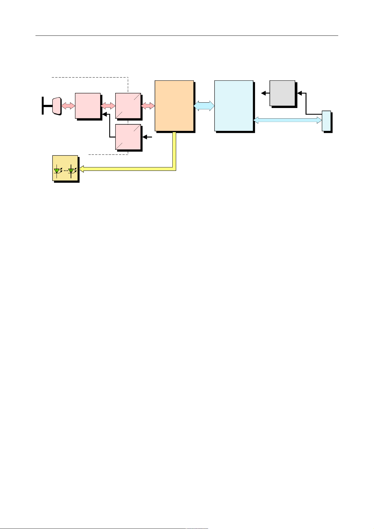
Figure 1: Block-circuit diagram of CAN-USB/2 module
The CAN-USB/2 module is an intelligent CAN interface with an ARM7 micro controller for local
CAN data management. The module supports the USB 2.0 Hi-Speed interface with data transfer
rates of 480 Mbit/s.
The ISO 11898-compliant CAN interface allows a maximum data transfer rate of 1 Mbit/s. Like
many other features of CAN interfaces, the bit rate can be set by means of software. CAN interface
and other voltage potentials are electrically isolated by means of a digital isolator and DC/DC
converters.
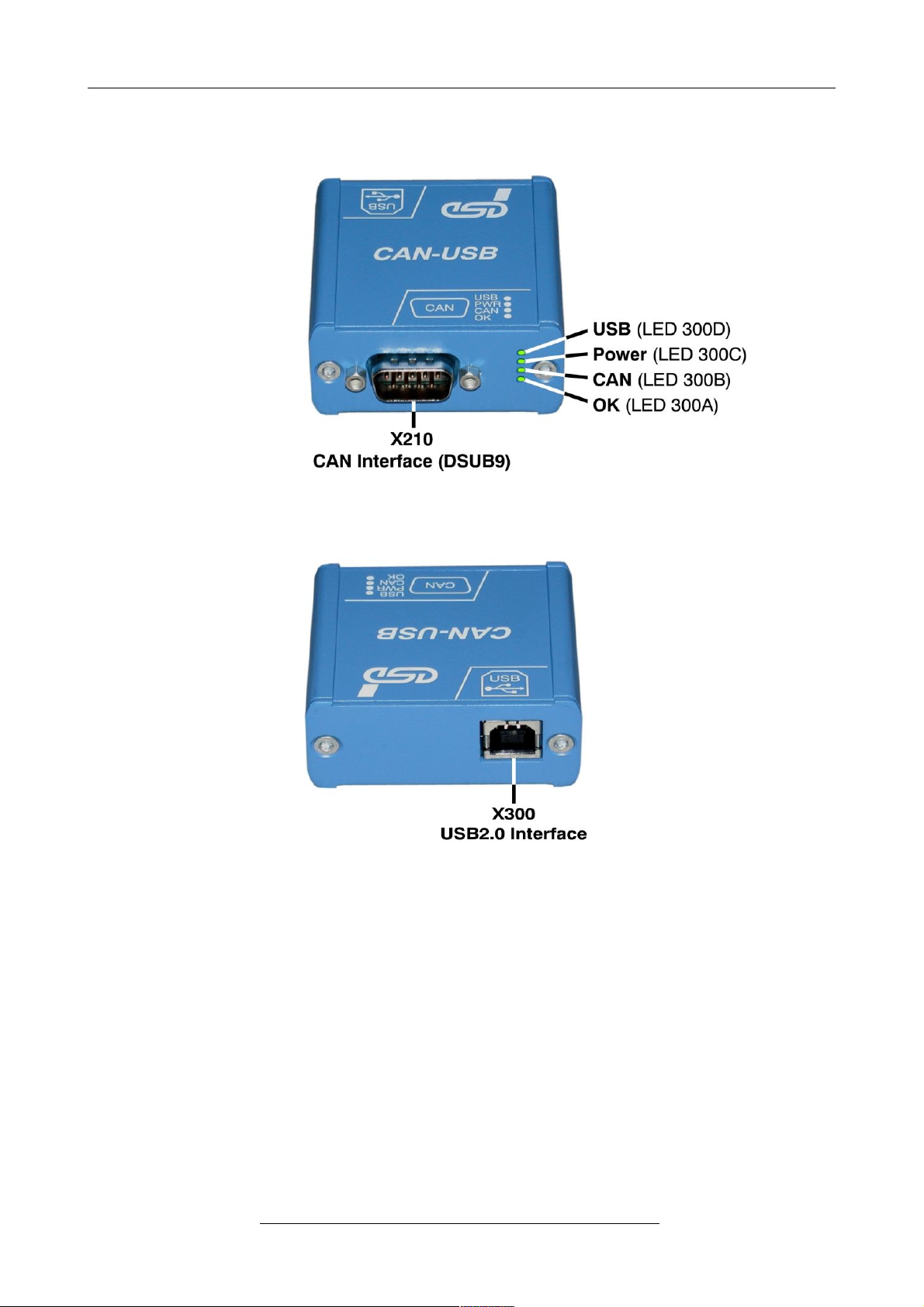
The supply voltage is fed via the USB bus. The module is equipped with four green LEDs in the
front panel which indicate the current module status.
CAN-USB/2
Hardware Manual • Doc. No.: C.2066.21 / Rev. 1.4
Page 7 of 25
+5 V=
+5 V=
Physical
CAN
Layer
C
A
N
B
U
S
CAN
ARM 7
Microcontroller
USB Controller
LEDs
Digital
Isolator
Electrical Isolation
DC/DC
Converter
DSUB9
CiA pinning
Power
Supply
5 V(DC)
USB-
Connector
Page 7
Case View with LED and Connector Description
2. Case View with LED and Connector Description
Figure 2: PCB top view
Figure 3: USB Interface
Page 8 of 25
Hardware Manual • Doc. No.: C.2066.21 / Rev. 1.4
CAN-USB/2
Page 8
Case View with LED and Connector Description
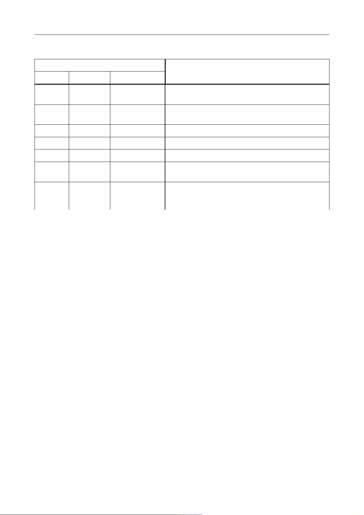
2.1 LED-Displays
LED
NAME Number Status
Description
USB LED300D
on
USB module is enumerated
(a node-ID is assigned to the USB module)
Power LED300C
on
module is in operation,
the 5 V power supply is applied to the module
CAN LED300B on data is received or send on the CAN bus
OK LED300A on CAN interface is initialized, bit rates are set
off bit rate not set
fast flashing
(appr. 10 Hz)
CAN interface is initialized and in mode ‘Listen Only’;
the bit rate is already set
slow flashing
(appr. 1 Hz)
CAN interface is initialized and in mode ‘Automatic
Baudrate Detection’ (from firmware version 1.0.0.4
and CAN driver version 2.5.2 on)
Table 1: Description of LED display
CAN-USB/2
Hardware Manual • Doc. No.: C.2066.21 / Rev. 1.4
Page 9 of 25
Page 9
Hardware Installation
3. Hardware Installation
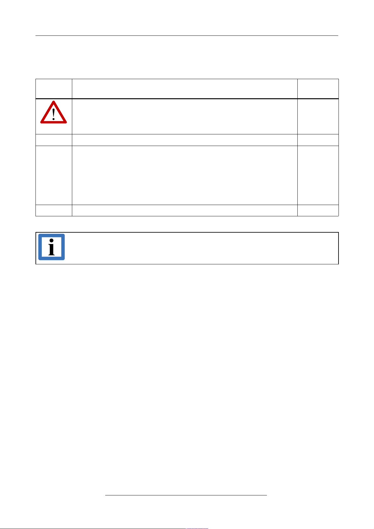
To put the CAN-USB/2 into operation, please follow the installation notes.
Step Procedure
see
page
Read the safety instructions at the beginning of this document
carefully, before you start with the hardware installation!
4
1. Connect the CAN-USB/2-module with the USB bus of the PC -
2. Please note that the CAN bus has to be terminated at both ends! esd
offers special T-connectors and termination connectors. Additionally the
CAN_GND signal has to be connected to earth at exactly one point in
the CAN network. Therefore the CAN termination connectors offered by
esd have got a grounding contact.
A CAN participant with a CAN interface which is not electrically isolated
corresponds to the grounding of the CAN-GND.
-
3. Switch on the power supply voltage of the CAN-USB/2. -
Note:
The software installation is described in the manual ‘CAN-API, Installation Guide’.
Page 10 of 25
Hardware Manual • Doc. No.: C.2066.21 / Rev. 1.4
CAN-USB/2
Page 10
Technical Data
4. Technical Data
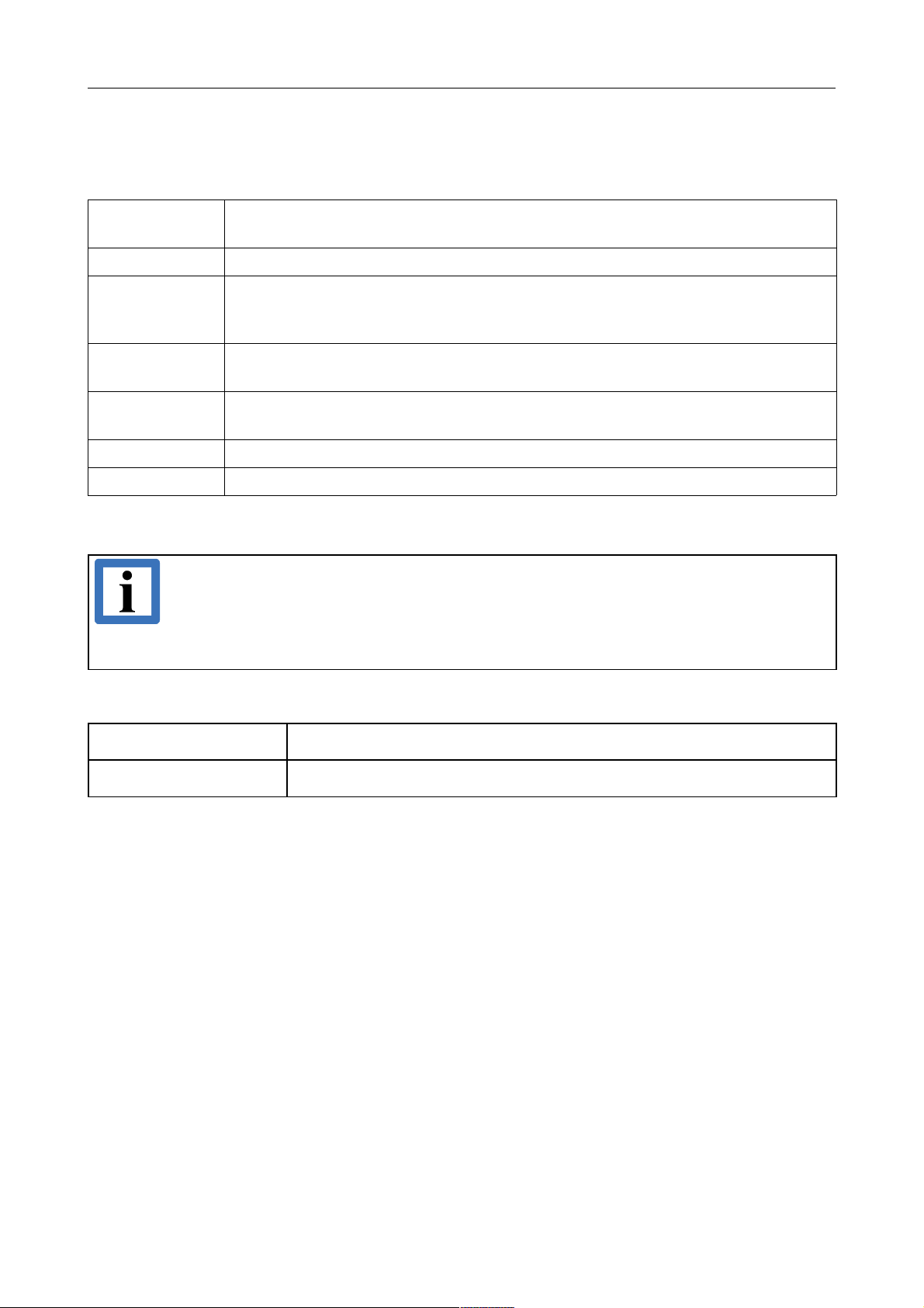
4.1 General Technical Data
Temperature
range
0...50°C ambient temperature
Humidity 90 %, non-condensing
Power supply
via USB 2.0 bus,
nominal voltage: 5 V
current consumption: max. 250 mA *
Connectors
X210 (DSUB9/male) - CAN bus
X300 (USB socket, series B) - USB bus
Case
dimensions
55 mm x 55 mm x 25 mm
IP-rating IP 40
Weight 70 g
Table 2: General data of the module
Note:
Please note that the current consumption of the module of 250 mA has to be supplied
(high powered bus-powered device).The maximum current consumption of 250 mA has
to be guaranteed also if a hub is used. Therefore it is highly recommended to use a
self-powered hub.
4.2 USB-Interface and Microcontroller
USB-interface USB 2.0, bit rate up to 480 Mbit/s
Microcontroller ARM7 microcontoller
Table 3: USB interface and microcontroller
CAN-USB/2
Hardware Manual • Doc. No.: C.2066.21 / Rev. 1.4
Page 11 of 25
Page 11
Technical Data
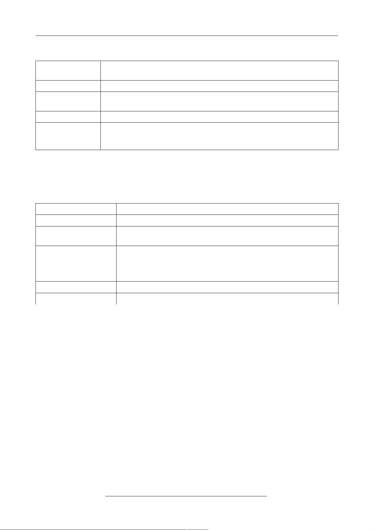
4.3 CAN Interface
Number of CAN
interfaces
1
CAN protocol ISO 11898-1 (11 and 29 bit CAN identifier are supported)
Physical Layer
CAN High Speed interface according to ISO 11898-2, transmission rate
programmable from 10 Kbit/s to 1 Mbit/s
Bus termination terminating resistor has to be set externally, if required
Electrical isolation
of CAN-interfaces
from other units
via digital isolators and DC/DC-converters
Table 4: Data of the CAN interface
4.4 Serial Interface
Number 4 asynchronous serial interfaces
Controller integrated in CPU or external DUART
Bit rate
Value range: 9600 Baud ... 115200 Baud
Default setting: 9600 Baud, 8 Bit, No Parity 1 Stop-Bit
Physical Interface
Serial 1: RS232 with RxD, TxD, RTS CTS, DSR, DTR
Serial 2: RS232 with RxD, TxD
Serial 3: RS485
Serial 4:
Software Standard operating system driver
Connector 9-pin DSUB
Table 5: Data of the serial interface
4.5 Software Support
Device drivers for Windows® and Linux® are available. Drivers for other operating systems,
especially real-time operating systems, are available on request.
Page 12 of 25
Hardware Manual • Doc. No.: C.2066.21 / Rev. 1.4
CAN-USB/2
Page 12
Connector Assignments
5. Connector Assignments
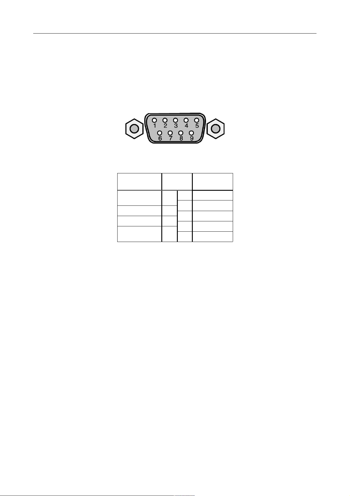
5.1 CAN Interface at DSUB9 Connector
Device connector: RJ45 socket, 8-pin
Pin Position:
Pin Assignment:
Signal Pin Signal
1
reserved
CAN_GND
62CAN_L
CAN_H
73CAN_GND
reserved
84reserved
reserved
95Shield
Signal Description:
CANx_L, CANx_H ... CAN signals of the CAN interface x (x... 1 - 4)
CANx_GND... reference potential of the local CAN physical layer of CAN interface x
(x... 1 - 4)
- ... reserved for future applications, do not connect!
CAN-USB/2
Hardware Manual • Doc. No.: C.2066.21 / Rev. 1.4
Page 13 of 25
Page 13
Connector Assignments
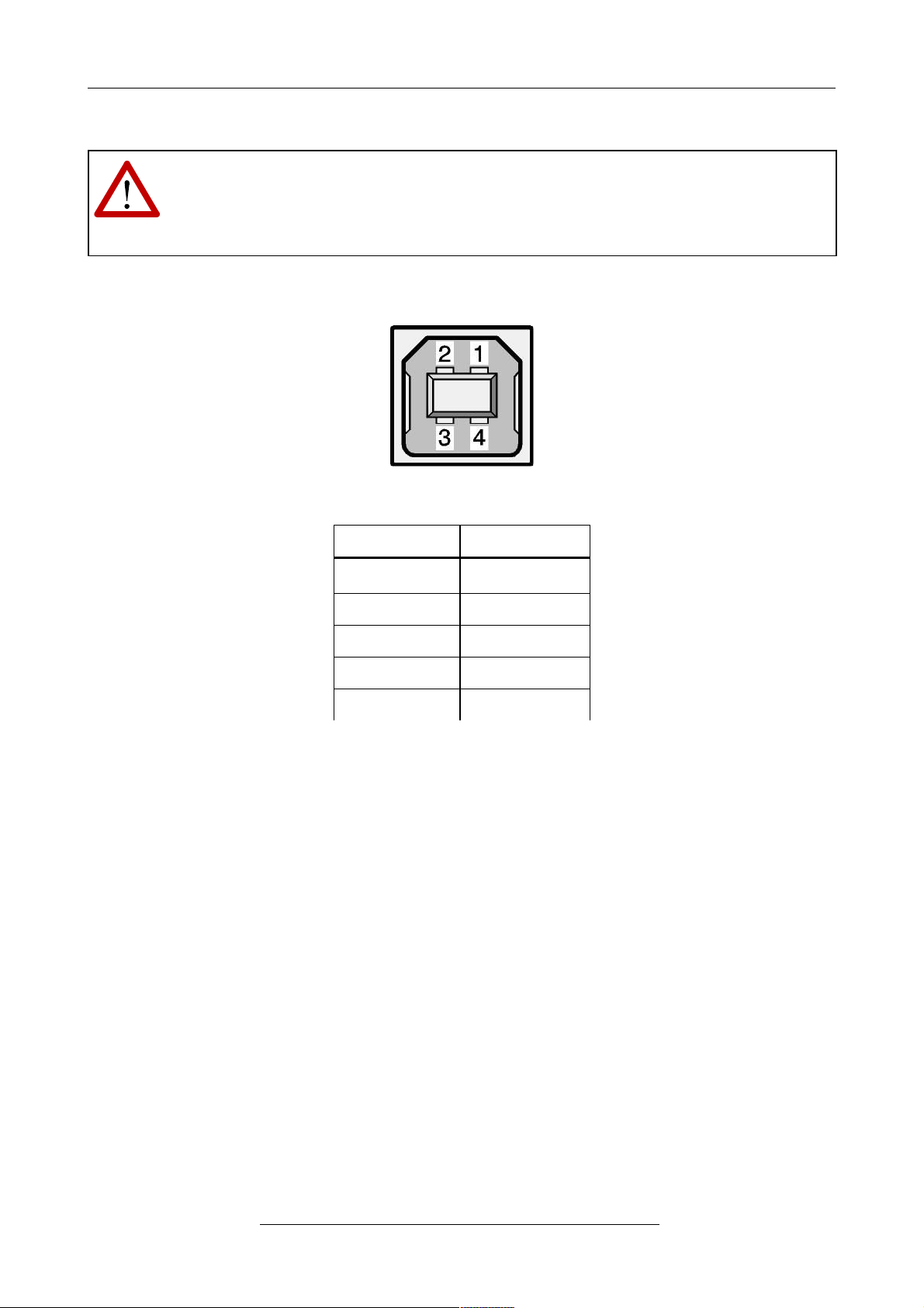
5.2 USB Socket
Note:
The module may only be operated at USB nets with USB interface version numbers ≥
1.1-interface! Using versions earlier than 2.0 reduces the data transfer rate.
Pin Position:
Pin Assignment:
Pin Signal
1
V
BUS
2 D-
3 D+
4 GND
Shell Shield
USB socket (series B)
Page 14 of 25
Hardware Manual • Doc. No.: C.2066.21 / Rev. 1.4
CAN-USB/2
Page 14
Correctly Wiring Electrically Isolated CAN Networks
6. Correctly Wiring Electrically Isolated CAN Networks
For the CAN wiring all applicable rules and regulations (EC, DIN), e.g. regarding electromagnetic
compatibility, security distances, cable cross-section or material, have to be met.
6.1 Light Industrial Environment (Single Twisted Pair Cable)
6.1.1 General Rules
Note:
esd grants the EC Conformity of the product, if the CAN wiring is carried out with at
least single shielded single twisted pair cables that match the requirements of ISO
118982-2. Single shielded double twisted pair cable wiring as described in chapter 6.2.
ensures the EC Conformity as well.
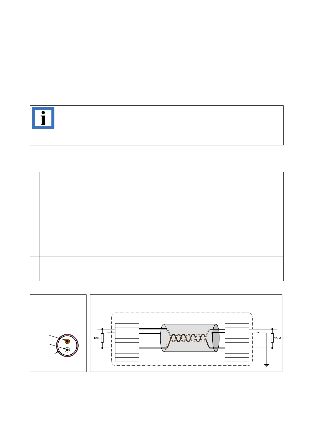
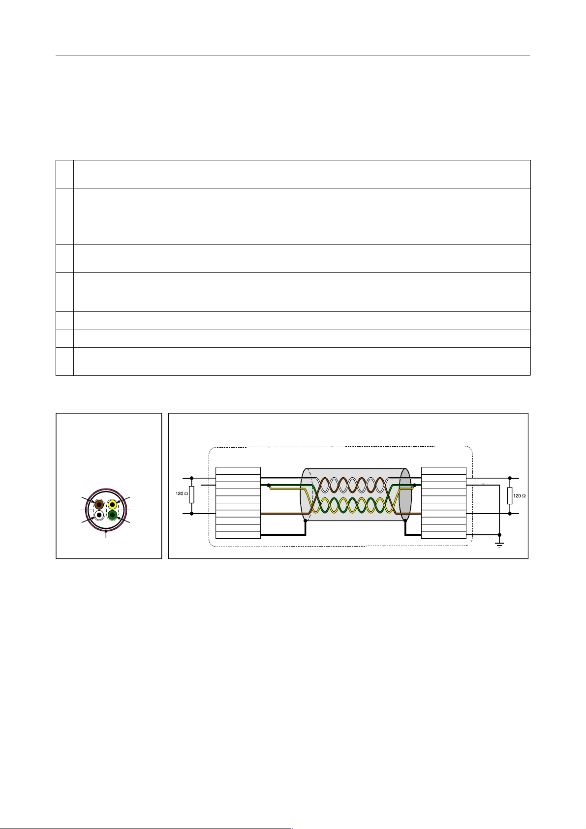
The following general rules for CAN wiring with single shielded single twisted pair cable must be
followed:
1
A cable type with a wave impedance of about 120 Ω ±10% with an adequate wire cross-section
(0.22 mm²) has to be used. The voltage drop over the wire has to be considered!
2
For light industrial environment use at least a two-wire CAN cable. Connect
•• the two twisted wires to the data signals (CAN_H, CAN_L) and
the cable shield to the reference potential (CAN_GND)!
3
The reference potential CAN_GND has to be connected to the functional earth (FE) at exactly one
point.
4
A CAN net must not branch (exception: short cable stubs) and has to be terminated with the
characteristic impedance of the line (generally 120 Ω ±10%) at both ends (between the signals CAN_L
and CAN_H and not at GND)!
5
Keep cable stubs as short as possible (l < 0.3 m)!
6
Select a working combination of bit rate and cable length.
7
Keep away cables from disturbing sources. If this cannot be avoided, double shielded wires are
recommended.
Figure. 4: CAN wiring for light industrial environment
CAN-USB/2
Hardware Manual • Doc. No.: C.2066.21 / Rev. 1.4
Page 15 of 25
CAN GND
CAN_H
CAN_GND
n.c.
n.c.
n.c.
n.c.
CAN_L
1
4
5
6
7
9
2
3
8
9
1
4
5
6
7
3
8
2
earth (FE)
CAN_L
CAN_H
CAN_GND
Single shielded
twisted pa ir cable
(two-wire cable,
1x 2x 0.22mm²)
CAN_GND
(at wire shield)
Wire Layout
Signal assignment of single shielded twisted pair cable
with earth and termination
n.c.
n.c.
n.c.
n.c.
n.c.
n.c.
n.c.
n.c.
n.c.
n.c.
n.c.
n.c.
n.c.
n.c.
n.c. = not connected
DSUB9 connector
(female or male)
pin designation
connector case connector case
DSUB9 connector
(female or male)
pin designation
CAN wire with connectors
Page 15
Correctly Wiring Electrically Isolated CAN Networks
6.1.2 Cabling
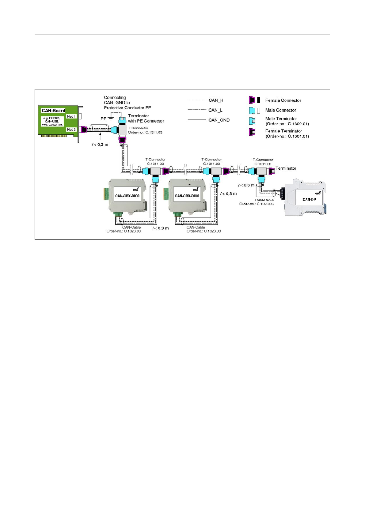
● for devices which have only one CAN connector per net use T-connector and stub (shorter
than 0.3 m) (available as accessory)
Figure. 5: Example for proper wiring with single shielded single twisted pair wires
6.1.3 Termination
● Use external termination plugs, because they can be rediscovered more easily than internal
terminations within the CAN devices!
● 9-pin DSUB-termination connectors with male and female contacts and earth terminal are
available as accessories
Page 16 of 25
Hardware Manual • Doc. No.: C.2066.21 / Rev. 1.4
CAN-USB/2
Page 16
Correctly Wiring Electrically Isolated CAN Networks
6.2 Heavy Industrial Environment (Double Twisted Pair Cable)
6.2.1 General Rules
The following general rules for the CAN wiring with single shielded double twisted pair cable must
be followed:
1
A cable type with a wave impedance of about 120 Ω ±10% with an adequate wire cross-section
(0.22 mm²) has to be used. The voltage drop over the wire has to be considered!
2
For heavy industrial environment use a four-wire CAN cable. Connect
•
•
•
two twisted wires to the data signals (CAN_H, CAN_L) and
the other two twisted wires to the reference potential (CAN_GND) and
the cable shield to functional earth (FE) at least at one point!
3
The reference potential CAN_GND has to be connected to the functional earth (FE) at exactly one
point.
4
A CAN bus line must not branch (exception: short cable stubs) and has to be terminated with the
characteristic impedance of the line (generally 120 Ω ±10%) at both ends (between the signals CAN_L
and CAN_H and not at GND)!
5
Keep cable stubs as short as possible (l < 0.3 m)!
6
Select a working combination of bit rate and cable length.
7
Keep away CAN cables from disturbing sources. If this can not be avoided, double shielded cables are
recommended.
Figure. 6: CAN wiring for heavy industrial environment
CAN-USB/2
Hardware Manual • Doc. No.: C.2066.21 / Rev. 1.4
Page 17 of 25
CAN GND
CAN_L
CAN_H
CAN_GND
n.c.
n.c.
n.c.
n.c.
n.c.
n.c.
n.c.
n.c.
n.c.
n.c.
CAN_L
CAN_H
CAN_G ND
Shield
CAN_G ND
twisted
twisted
5
6
7
9
8
1
4
3
2
9
1
4
5
6
7
3
8
2
Single shielded
double twisted pair cable
(four-wire cable,
2x 2x 0.22mm²)
wire shield
earth (FE)
Wire Layout
(Example)
Signal assignment of single shielded double twisted pair cable
with earth and termination
n.c. = not connected
DSUB9 connector
(female or male)
pin designation
connector case
DSUB9 connector
(female or male)
pin designation
CAN cable with connectors
connector case
Page 17
Correctly Wiring Electrically Isolated CAN Networks
6.2.2 Device Cabling
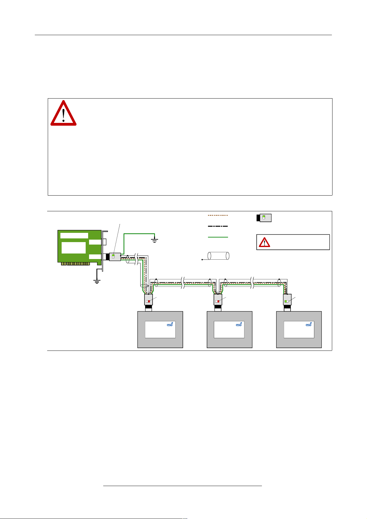
● To connect CAN devices which are equipped with one CAN connector per net, use
T-connectors and cable stubs (shorter than 0.3 m).
Attention:
If single shielded double twisted pair cables are used, realize the T-connections by
means of connectors that support connection of two CAN cables at one connector
where the cable’s shield is looped through e.g. DSUB9 connector from ERNI
(ERBIC CAN BUS MAX, order no.:154039).
The usage of esd’s T-connector type C.1311.03 is not recommended for single
shielded double twisted pair cables because the shield potential of the conductive
DSUB housing is not looped through this T-connector type.
Furthermore, mixed use of single twisted and double twisted cables should be
avoided!
Figure. 7: Example for proper wiring with single shielded double twisted pair cables
6.2.3 Termination
● Use external termination plugs, because they can later be rediscovered more easily than
internal terminations within the CAN devices!
● A 9-pin DSUB-connector with integrated switchable termination resistor can be ordered e.g.
from ERNI (ERBIC CAN BUS MAX, female contacts, order no.:154039).
Page 18 of 25
Hardware Manual • Doc. No.: C.2066.21 / Rev. 1.4
CAN-USB/2
CAN_L
CAN_GND
CAN_H
FE
esd
CAN Modul
Shield (Abschirmung)
esd
CAN Modul
esd
CAN Modul
CAN_GND connected
to functional earth (FE)
at exactly one point
Net 2
Net 1
e.g. CPCI /405,
PMC-CAN/3 31,
EPPC-405, e tc.
CAN-Board
termination
switched OFF
CAN T-Connector
(DSUB9 connector, female),
with switchable
termination
CAN
T-Connector
connected to earth (FE)
via computer housing
termination
switched OFF
CAN
T-Connector
CAN
T-Connector
termination
switched
ON
termination
switched
ON
Attention:
Watch for the correct positi on of the
termination sw itches at t he connectors!
CAN
T-Connector
Page 18
Correctly Wiring Electrically Isolated CAN Networks
6.3 Electrical Grounding
● CAN_GND has to be connected between the CAN devices, because esd CAN devices are
electrically isolated from each other!
● CAN_GND has to be connected to the earth potential (FE) at exactly one point of the
network!
● Each CAN interface without electrically isolated interface acts as an earthing point. For this
reason do not connect more than one CAN device without electrically isolated CAN
interface!
● Earthing can e.g. be made at a connector/T-connector.
6.4 Bus Length
● Optical couplers are delaying the CAN signals. esd modules typically reach a wire length of
37 m at 1 Mbit/s within a closed net without impedance disturbances like e.g. cable stubs
>> 0.3 m.
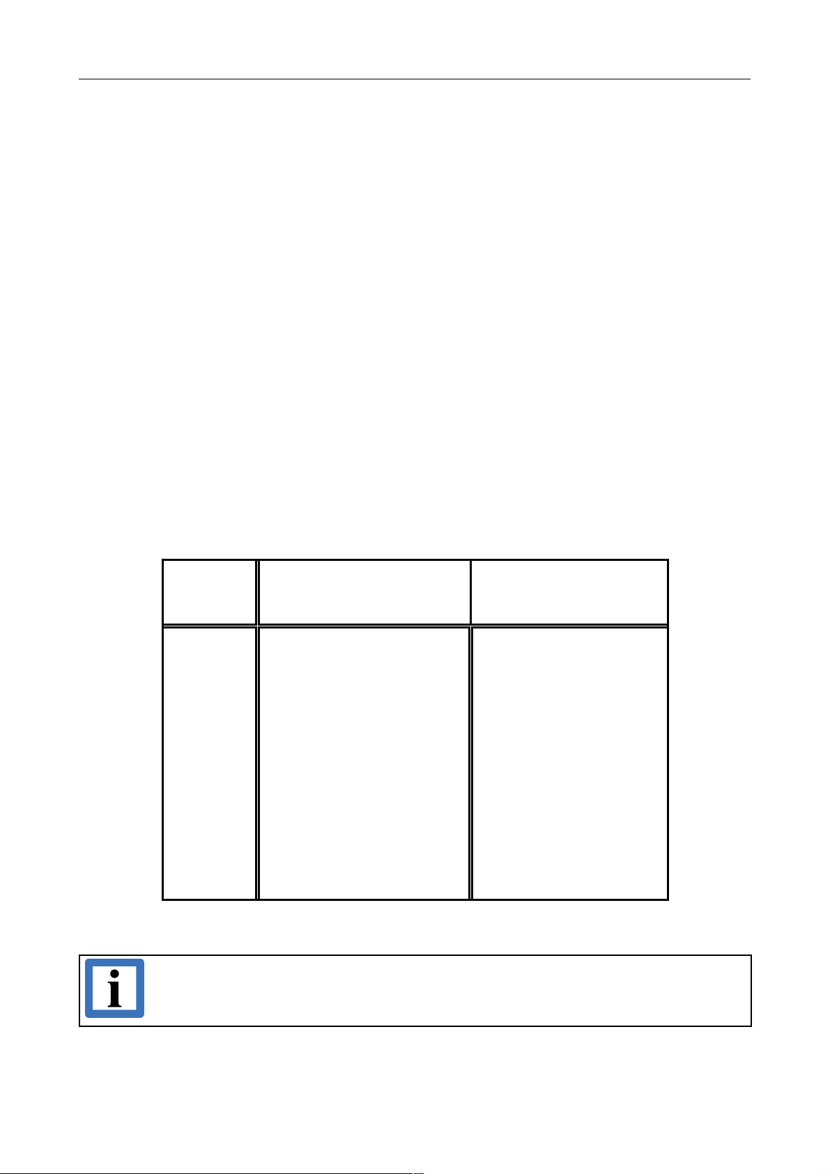
Bit rate
[Kbits/s]
Typical values of reachable
wire length with esd
interface l
max
[m]
CiA recommendations
(07/95) for reachable wire
lengths l
min
[m]
1000
800
666.6
500
333.3
250
166
125
100
66.6
50
33.3
20
12.5
10
37
59
80
130
180
270
420
570
710
1000
1400
2000
3600
5400
7300
25
50
-
100
-
250
500
650
-
1000
-
2500
-
5000
Table 6: Recommended cable lengths at typical bit rates (with esd-CAN interfaces)
Note:
Please note the recommendations according to ISO 11898 for the selection of the cross
section of the wire depending of the wire length.
CAN-USB/2
Hardware Manual • Doc. No.: C.2066.21 / Rev. 1.4
Page 19 of 25
Page 19
Correctly Wiring Electrically Isolated CAN Networks
6.5 Examples for CAN Cables
6.5.1 Cable for Light Industrial Environment Applications (Two-Wire)
Manufacturer Cable Type
U.I. LAPP GmbH
Schulze-Delitzsch-Straße 25
70565 Stuttgart
Germany
www.lappkabel.com
e.g.
UNITRONIC ®-BUS CAN UL/CSA (1x 2x 0.22)
(UL/CSA approved) Part No.: 2170260
UNITRONIC ®-BUS-FD P CAN UL/CSA (1x 2x 0.25)
(UL/CSA approved) Part No.: 2170272
ConCab GmbH
Äußerer Eichwald
74535 Mainhardt
Germany
www.concab.de
e. g.
BUS-PVC-C (1x 2x 0.22 mm²) Order No.: 93 022 016 (UL appr.)
BUS-Schleppflex-PUR-C (1x 2x 0.25 mm²) Order No.: 94 025 016 (UL appr.)
6.5.2 Cable for Heavy Industrial Environment Applications (Four-Wire)
Manufacturer Cable Type
U.I. LAPP GmbH
Schulze-Delitzsch-Straße 25
70565 Stuttgart
Germany
www.lappkabel.com
e.g.
UNITRONIC ®-BUS CAN UL/CSA (2x 2x 0.22)
(UL/CSA approved) Part No.: 2170261
UNITRONIC ®-BUS-FD P CAN UL/CSA (2x 2x 0.25)
(UL/CSA approved) Part No.: 2170273
ConCab GmbH
Äußerer Eichwald
74535 Mainhardt
Germany
www.concab.de
e. g.
BUS-PVC-C (2x 2x 0.22 mm²) Order No.: 93 022 026 (UL appr.)
BUS-Schleppflex-PUR-C (2x 2x 0.25 mm²) Order No.: 94 025 026 (UL appr.)
Note:
Configured CAN cables can be ordered from esd.
Page 20 of 25
Hardware Manual • Doc. No.: C.2066.21 / Rev. 1.4
CAN-USB/2
Page 20
CAN Troubleshooting Guide
7. CAN Troubleshooting Guide
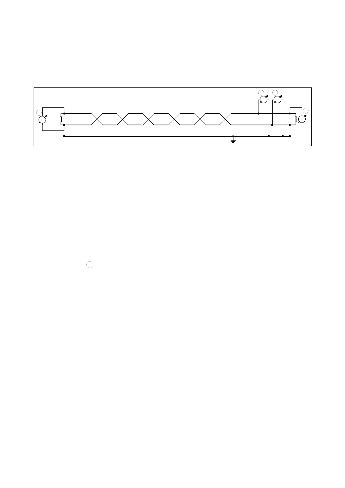
The CAN Troubleshooting Guide is a guide to find and eliminate the most frequent hardware-error
causes in the wiring of CAN-networks.
Figure. 8: Simplified diagram of a CAN network
7.1 Termination
The termination is used to match impedance of a node to the impedance of the transmission line
being used. When impedance is mismatched, the transmitted signal is not completely absorbed by
the load and a portion is reflected back into the transmission line. If the source, transmission line
and load impedance are equal these reflections are eliminated. This test measures the series
resistance of the CAN data pair conductors and the attached terminating resistors.
To test it, please
1. Turn off all power supplies of the attached CAN nodes.
2. Measure the DC resistance between CAN_H and CAN_L at the ends of
the network (see figure above) and at the centre of the network (if the network cable
consists of more than one line section).
The measured value should be between 50 Ω and 70 Ω. The measured value should be nearly the
same at each point of the network.
If the value is below 50 Ω, please make sure that:
- there is no short circuit between CAN_H and CAN_L wiring
- there are not more than two terminating resistors
- the nodes do not have faulty transceivers.
If the value is higher than 70 Ω, please make sure that:
- there are no open circuits in CAN_H or CAN_L wiring
- your bus system has two terminating resistors (one at each end) and that they are 120 Ω
each.
CAN-USB/2
Hardware Manual • Doc. No.: C.2066.21 / Rev. 1.4
Page 21 of 25
1
120
CAN_H
CAN_GND
CAN_L
CAN_L
CAN_H
CAN_GND
V
120
2
3
1
V
1
Page 21
CAN Troubleshooting Guide
7.2 Electrical Grounding
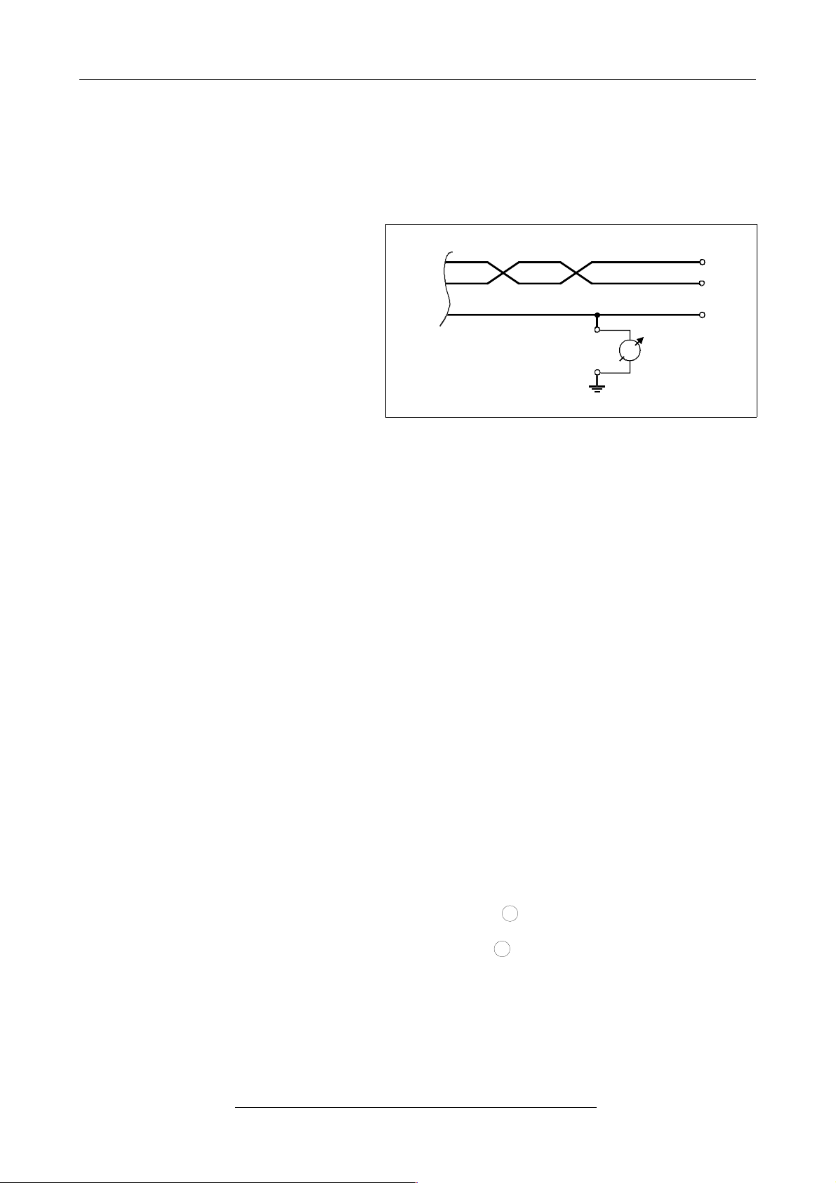
The CAN_GND of the CAN network has to be connected to the functional earth potential (FE) at
only one point. This test will indicate if the CAN_GND is grounded in several places.
To test it, please
1.
2.
3.
Disconnect the CAN_GND from the
earth potential (FE).
Measure the DC resistance
between CAN_GND and earth
potential (see figure on the right).
Connect CAN_GND to earth potential.
Figure. 9: Simplified schematic diagram of ground test measurement
The resistance should be higher than 1 MΩ. If it is lower, please search for additional grounding of
the CAN_GND wires.
7.3 Short Circuit in CAN Wiring
A CAN bus might possibly still be able to transmit data if there is a short circuit between CAN_GND
and CAN_L, but the error rate will increase strongly. Make sure that there is no short circuit
between CAN_GND and CAN_L!
7.4 CAN_H/CAN_L-Voltage
Each node contains a CAN transceiver that outputs differential signals. When the network
communication is idle the CAN_H and CAN_L voltages are approximately 2.5 volts. Faulty
transceivers can cause the idle voltages to vary and disrupt network communication.
To test for faulty transceivers, please
1. Turn on all supplies.
2. Stop all network communication.
3. Measure the DC voltage between CAN_H and GND
(see figure above).
4. Measure the DC voltage between CAN_L and GND
(see figure above).
Page 22 of 25
Hardware Manual • Doc. No.: C.2066.21 / Rev. 1.4
CAN-USB/2
2
3
>1M
CAN_H
CAN_GND
CAN_L
functional earth
(FE)
Page 22
CAN Troubleshooting Guide
Normally the voltage should be between 2.0 V and 4.0 V.
If it is lower than 2.0 V or higher than 4.0 V, it is possible that one or more nodes have faulty
transceivers. For a voltage lower than 2.0 V please check CAN_H and CAN_L conductors for
continuity. For a voltage higher than 4.0 V, please check for excessive voltage.
To find the node with a faulty transceiver please test the CAN transceiver resistance (see below).
7.5 CAN Transceiver Resistance Test
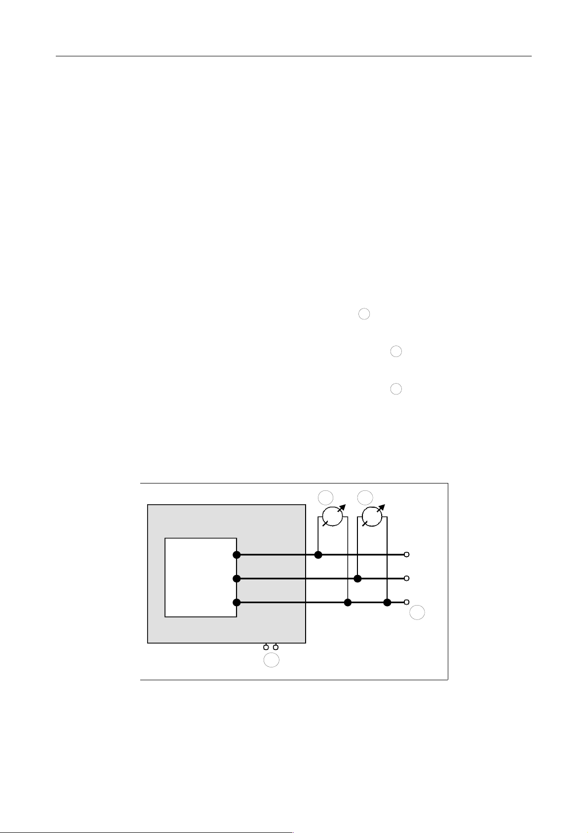
CAN transceivers have one circuit that controls CAN_H and another circuit that controls CAN_L.
Experience has shown that electrical damage to one or both of the circuits may increase the
leakage current in these circuits.
To measure the current leakage through the CAN circuits, please use an resistance measuring
device and:
1. Switch off the node and disconnect it from the network
(see figure below).
2. Measure the DC resistance between CAN_H and CAN_GND
(see figure below).
3. Measure the DC resistance between CAN_L and CAN_GND
(see figure below).
The measured resistance has to be about 500 kΩ for each signal. If it is much lower, the CAN
transceiver it is probably faulty.
Another sign for a faulty transceiver is a very high deviation between the two measured input
resistance (>> 200%).
Figure. 10: Measuring the internal resistance of CAN transceivers
CAN-USB/2
Hardware Manual • Doc. No.: C.2066.21 / Rev. 1.4
Page 23 of 25
4
5
6
CAN_H
CAN_GND
CAN_L
5 6
4
4
Power
CAN
transceiver
disconnect
power!
disconnect
CAN!
CAN node
Page 23
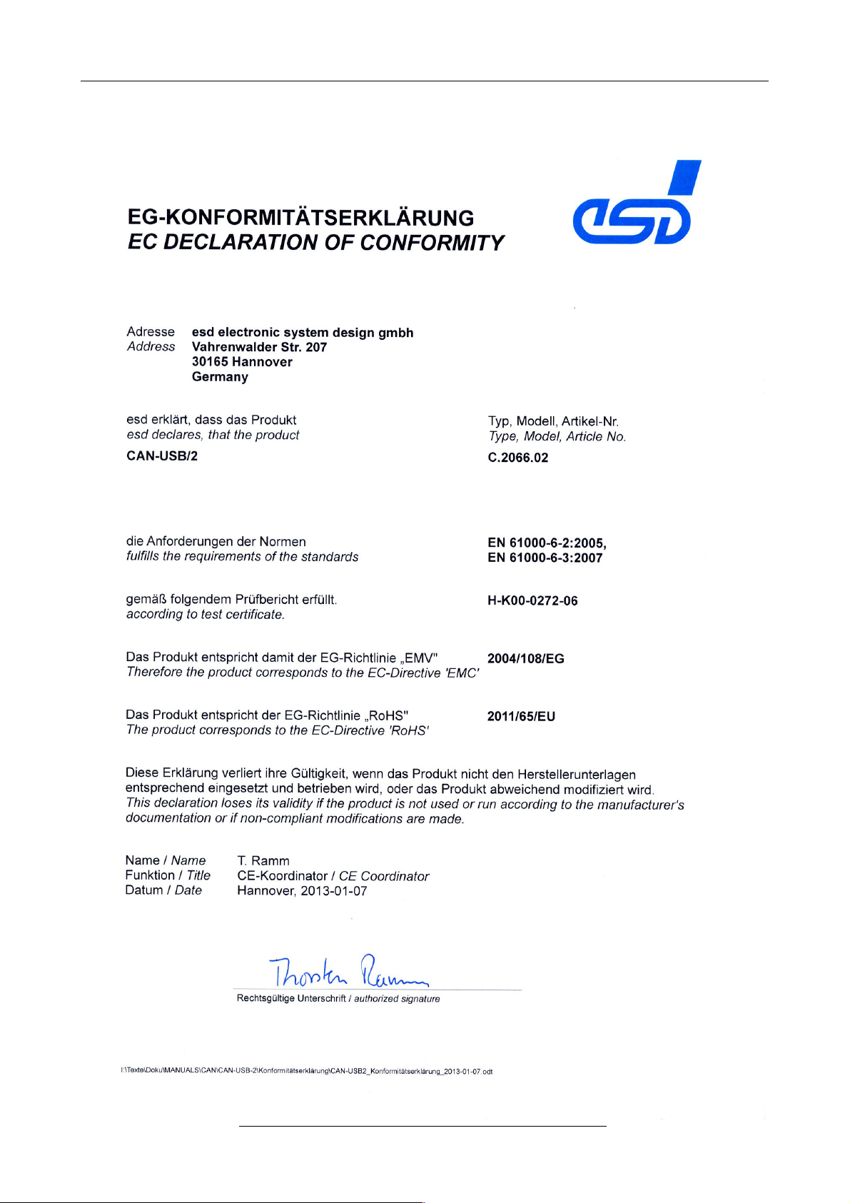
Declaration of Conformity
8. Declaration of Conformity
Page 24 of 25
Hardware Manual • Doc. No.: C.2066.21 / Rev. 1.4
CAN-USB/2
Page 24
Order Information
9. Order Information
Type Properties Order No.
CAN-USB/2 1 x CAN 2.0A/B, ISO 11898, USB 2.0 C.2066.02
* includes CAN layer 2 software driver on CD-ROM for Windows and Linux
Software
CANopen-LCD
Windows/Linux
CANopen® license for Linux and Windows incl. CDROM
C.1101.06
J1939 Stack for Windows
J1939 Stack for esd-CAN-Hardware, includes
Windows-XP object code, J1939 Simulation Tool,
esd CAN Windows driver license
C.1130.10
For detailed information about the driver availability of your special operating system, please contact our sales team.
Table 7: Order information
PDF Manuals
Manuals are available in English and usually in German as well. Available manuals are listed in the
following table.
Please download the manuals as PDF documents from our esd website www.esd.eu for free.
Manuals Order No.
CAN-USB/2-MD Hardware manual in German C.2066.21
CAN-USB/2-ME Hardware manual in English C.2066.21
CAN-API-ME
API manual 1/2: Functions (English)
API manual 2/2: Installation (English)
C.2001.21
J1939-ME J1939 software manual in English C.1130.21
CANopen-ME CANopen manuals in English C.2002.21
Table 8: Available manuals
Printed Manuals
If you need a printout of the manual additionally, please contact our sales team: [email protected] for
a quotation. Printed manuals may be ordered for a fee.
CAN-USB/2
Hardware Manual • Doc. No.: C.2066.21 / Rev. 1.4
Page 25 of 25
 Loading...