

Page 1

Revised Version: V1.0 on 2004/5/25
Quick Start Guide
ON
OFF
RS232
u
u
REC
θ
HOLDRS232 D/Q/
ALWAYS DISCHARGE THE CAPACITOR BEFORE TESTING
FORCE SENSE SENSE FORCE
P SAUTO
L/C/R
RANGEFREQ
TOL
CAL
REL
ON
OFF
RS232
u
u
REC
θ
HOLDRS232 D/Q/
ALWAYS DISCHARGE THE CAPACITOR BEFORE TESTING
FORCE SENSE
P SAUTO
RANGEFREQ L/C/R
SENSE FORCE
TOL
CAL
REL
This guide provides an overview. Detail User Manual is available
on the accompanying CD-ROM. Please execute the program of
“LCR.HTM ” in the CD-ROM, it will guide you to find the related
document.
P/N: 91-25177-1 Print in Taiwan
Copyright© 2004 LT. All rights reserved.
Page 2
SAFETY INFORMATION
In this manual, "WARNING", is reserved for condi ti o ns and actions that
pose hazard(s) to the user; "CAUTION", is reserved for conditions and
actions that may damage your meter. Before using the meter, read the
following safety information carefully.
1. Before applying power, ensure that power cord and the proper line
voltage indicated for power source being used.
2. This product is grounding through the grounding conductor of the
power cord. To avoid electric shock, the grounding conductor must
be connected to earth gr ound. Be fore making any connectio ns to th e
input terminals of the products, ensure that the properly grounded.
3. To avoid personal injury, never operate the instrument without
covers or panels removed.
4. Do not operate this product in wet, damp or explosive atmosphere.
5. This meter is for indoor use, altitude up to 2,000 m.
6. The warnings and precautions should be read and well understood
before the instrument is used.
7. Use this device only as specified in this manual; otherwise, the
protection provided by the meter may be impaired.
8. When measuring in-circuit components, first de-energi ze the circuits
before connecting to the test leads.
9. Discharge the capacitor before testing.
10. The meter is safety-certified in compliance with EN61010 (IEC
1010-1). EMC is certified in compliance with EN61326-1.
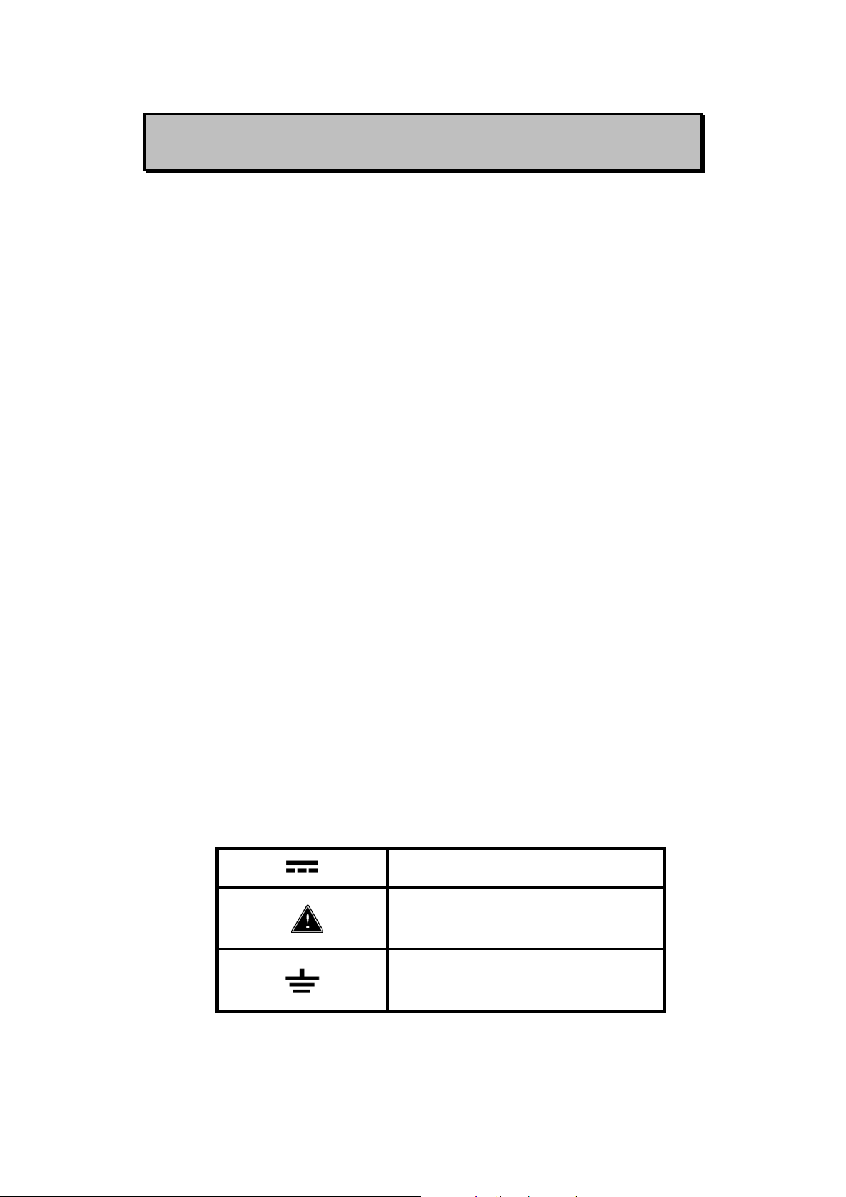
11. International electrical symbols used in this manual as follows:
DC - Direct Current
See Explanation In The Manual
Protective conductor terminated.
Table-1. International Electrical Symbols
2
Page 3
INTRODUCTION
The meter is a bench type instrument for testing inductance,
capacitance and resistance. If this device is damaged or something is
missing, contact the place of purchase immediately.
This 19,999-count L/C/R meter is a special microprocessor-controlled
meter for measuring functions of inductance, capacitance and
resistance. Extremely simple to operate, the instrument not only takes
absolute parallel mode measurements, but also capable of series mode
measurement. The meter provides direct and accurate measurements
of inductors, capacitors and resistors with different testing frequencies.
It is selectable for auto and manual ranging.
Front panel pushbuttons maximize the convenience of function and
feature selection such as data hold; maximum, minimum and average
record mode; relative mode; tolerance sorting mode; frequency and
L/C/R selection.
The test data can be transferred to PC through an optional full isolated
optical RS232C interface.
A tilt stand provides position flexibility for viewing and operating the
meter. Its portability and stackable design makes this valuable
instrument for electronic engineer, communications technician, schools
and laboratories using.
3
Page 4
FRONT PANEL ILLUSTRATION
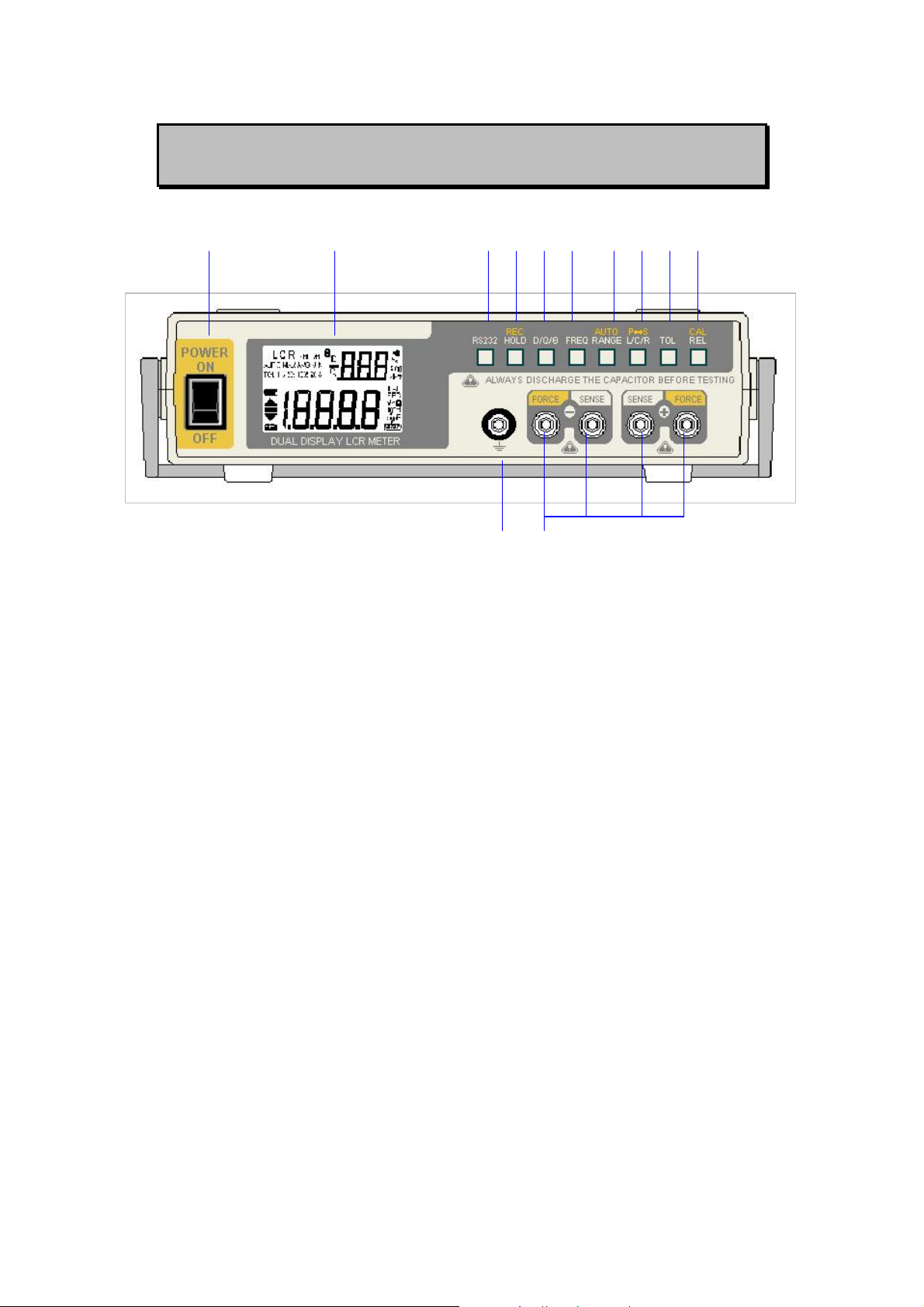
1 2 3 4 5 6 7 8 9 10
Figure-1. Front panel
1. POWER SWITCH: used to turn the power ON and OFF.
2. LCD display
3. RS232: Press this button to toggle RS232 function On/OFF.
4. HOLD (REC): Press this button to hold data. Press this button for
more than 1 second to enter Static Recording for Maximum,
Minimum and Average reading.
5. D/Q/θ: Press this button to select Dissipation factor, Quality factor
and Phase angle displays.
6. FREQ: Press this button to select test frequency.
7. RANGE (AUTO): Press this button to select measuring range.
Press this button for more than 1 second to set auto range.
8. L/C/R (P-S): Press this button to select Inductance, Capacitance
and Resistance measurements. Press this button for more than
one second to toggle parallel and series mode.
11 12
9. TOL: Tolerance mode selection button
10. REL (CAL): Relative mode and Calibration selection button
11. Protective Ground to be connected a plate for preventing noise
influence.
12. Input Terminals.
4
Page 5
REAR PANEL ILLUSTRATION
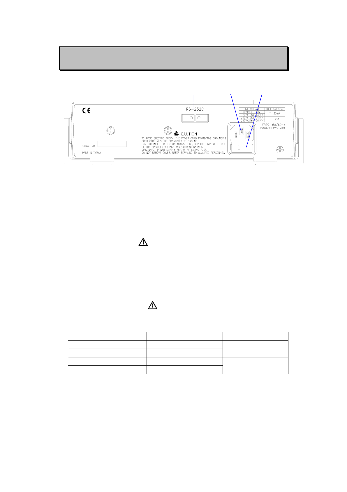
1 2 3
Figure-2. Rear Panel.
1. Optical RS-232 interface port.
2. Power cord socket.
3. Line voltage selector and fuse holder: to select line voltage and fuse
replacement.
CAUTIONS
In order to avoid damaging this instrument, make sure that the unit is
set to the correct line voltage for your area. Also make sure that the
correct fuse is used for the line voltage. These line voltages are 100V,
120V, 220V and 240V at 50/60HZ.
WARNING
To avoid damage the equipment use only specified fuse when change
the power line voltage. Please refer to following table
SELECTOR LINE VOLTAGE FUSE 5x20mm
100V 90~110V 50/60Hz
120V 108~132V 50/60Hz
220V 198~242V 50/60Hz
240V 216~264V 50/60Hz
Although this instrument is protected against reverse polarity damage
the circuit being powered may not include such protection. Always
carefully observe polarity incorrect polarity may damage the equipment
T 125mA
T 63mA
under test. Do not ex ceed the v oltag e rating o f the cir cuit being pow ered.
5
Page 6
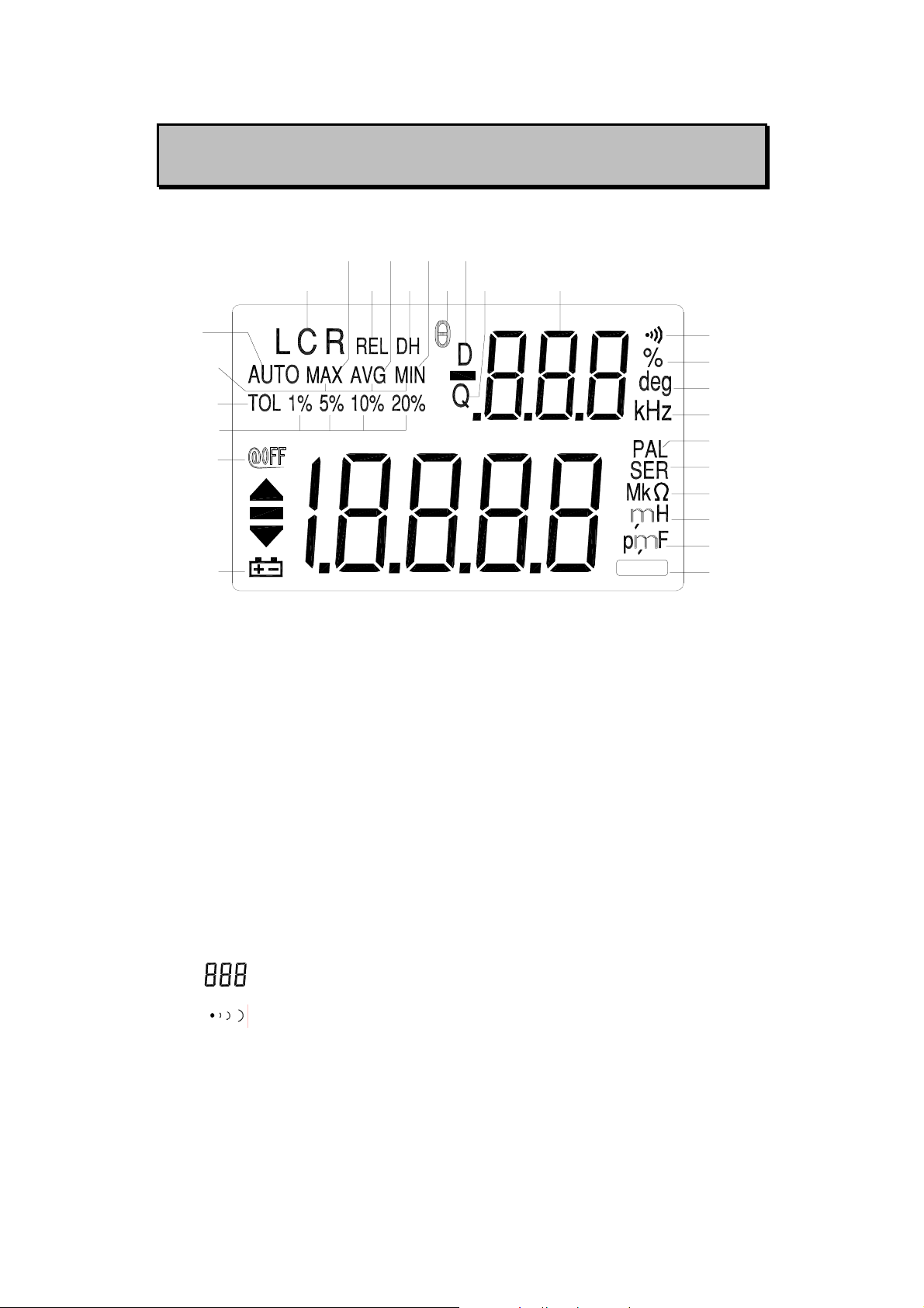
LCD DISPLAY ILLUSTRATION
34610
2
1
16
17
18
19
20
Figure-3. LCD Display.
1. AUTO: Auto-ranging indicator
2. LCR: L, C or R function indicator
119875
12
13
14
15
21
22
23
u
u
RS232
24
25
26
3. MAX: Maximum reading indicator
4. AVG: Average reading indicator
5. REL: Relative mode indicator
6. MIN: Minimum reading indicator
7. DH: Data hold indicator
8. Θ: Phase angle indicator
9. Q: Quality factor indicator
10. D: Dissipation factor indicator
11.
12.
13. %: Tolerance (percentage) indicator
14. deg: Phase angle degree indicator
15. kHz: Measuring frequency indicator
16. MAX AVG MIN: Recording mode indicators
17. TOL: Tolerance mode i ndi cat or
: Secondary display
: Beeper tone indicator for tolerance mode
6
Page 7
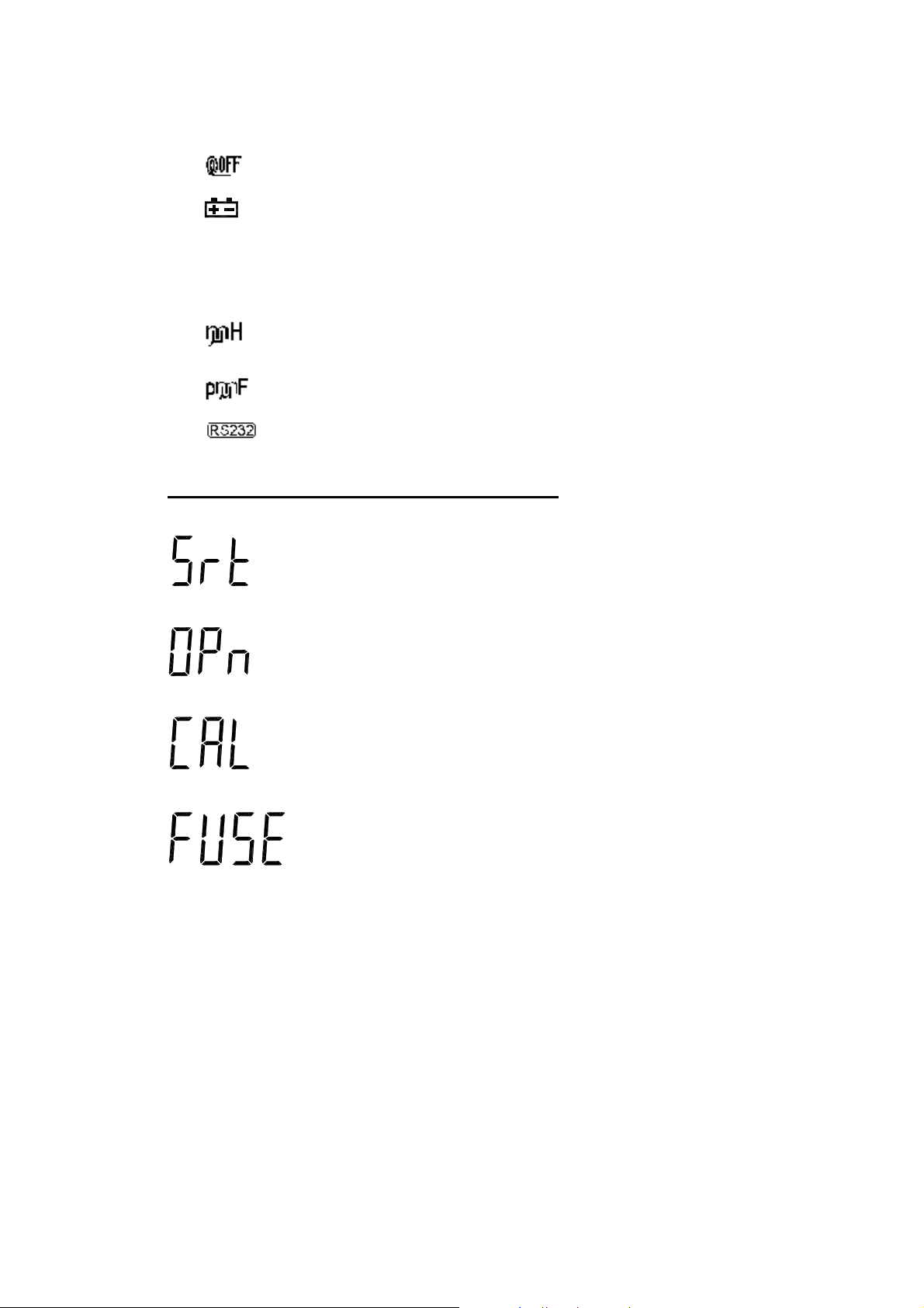
18. 1%5%10%20%: Tolerance sorting (percent) indicator
19.
20.
21. PAL: Parallel mode indicator
22. SER: Series mode indicator
23. MkΩ: Resistance (Ohm) indicator
24.
25.
26.
: Non-used.
: Non-used.
: Inductance (Henry) indicator
: Capacitance (Farad) indicator
: RS232 indicator
Special Indication Characters
: Indicates short connectors
: Indicates open connectors
: Indicates calibration mode
: Indicates damaged or open fuse
7
Page 8
MEASURING L/CR
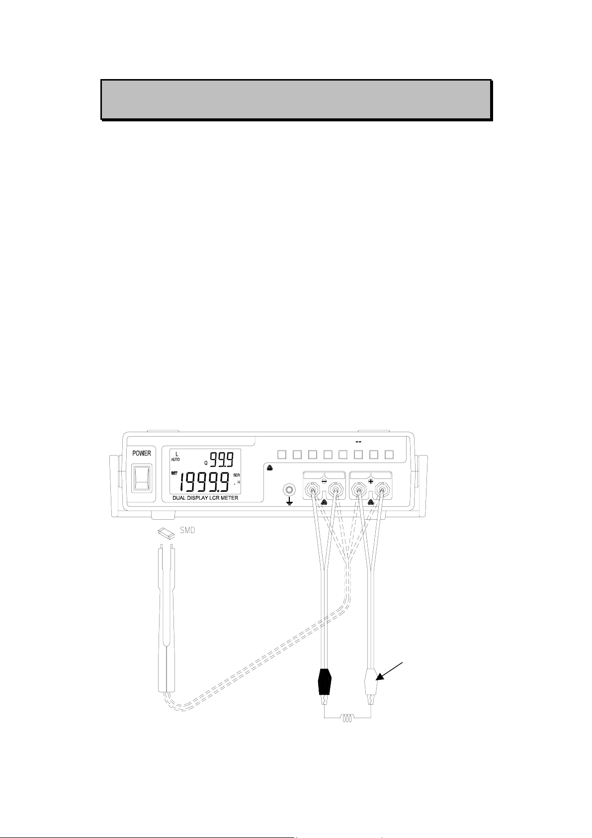
Inductance/ Capacitance/ Resistance Measurement
1. Press “L/C/R” button to select inductance (L), capacitance (C) or
resistance (R) measurement.
2. Connect the BNC ends of red clip or SMD Tweezers to “SENSE +”
and “FORCE +”, respectively.
3. Connect the BNC ends of black clip or SMD Tweezers to “SENSE
-” and “FORCE -”, respectively.
4. Connect the test clips to the component leads as required or using
SMD Tweezers to measure SMD component.
5. Press “FREQ” button to select testing frequency.
6. Press “D/Q/θ” button to select Q or D factor for secondary display
as necessary.
7. Remove your hands from clips then read the display readings.
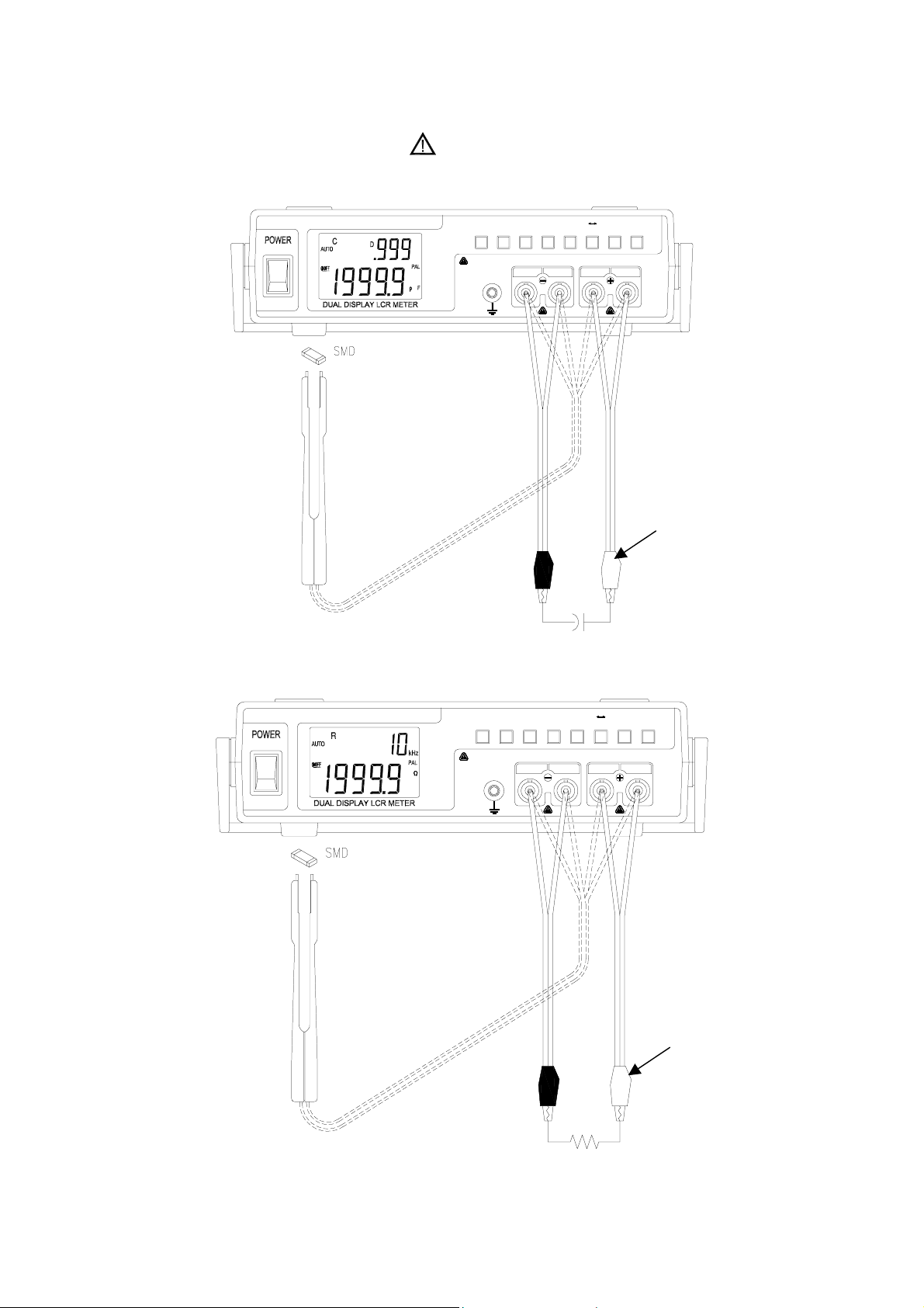
8. Please refer to Figure-4~6 for inductance, capacitance and
resistance measurement.
ON
OFF
REC
θ
HOLDRS232 D/Q/
ALWAYS DISCHARGE THE CAPACITOR BEFORE TESTING
u
FORCE SENSE
P SAUTO
RANGEFREQ L/C/R
SENSE FORCE
CAL
TOL
REL
Red clip
Figure-4. Inductance Measurement
8
Page 9
WARNING
To avoid electrical hazards, discharge the capacitor to be tested before
measuring.
REC
θ
HOLDRS232 D/Q/
ON
OFF
ALWAYS DISCHARGE THE CAPACITOR BEFO RE TEST ING
FORCE SENSE
Figure-5. Capacitance Measurement.
P SAUTO
RANGEFREQ L/C/R
SENSE FORCE
CAL
REL
TOL
Red Clip
ON
OFF
REC
θ
HOLDRS232 D/Q/
ALWAYS DISCHARGE THE CAPACITOR BEFORE TESTING
FORCE SENSE
P SAUTO
RANGEFREQ L/C/R
SENSE FORCE
TOL
CAL
REL
Red Clip
Figure-6. Resistance Measurement.
9
Page 10
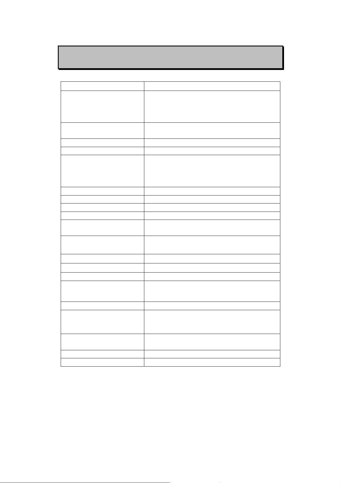
GENERAL SPECIFICATION
Parameters Measured
Measuring Circuit Mode Inductance (L)
–Defaults to series mode
Capacitance/ Resistance (C/R)
-Defaults to parallel mode
Displays L/C/R: Maximum display 19999
D/Q: Maximum display 999 (Auto Range).
Ranging Mode Auto & Manual
Measuring Te rminals 4 BNC terminals with one ground terminal
Test Frequency
Accuracy: ±0.1 %
Backlit display Included
Tolerance mode 1%, 5%, 10%, 20%
Test Signal Level 0.8Vrms approx.
Measuring Rate 1 time/second, nominal
Response time
Temperature Coefficient
Operation Temperature
Storage Temperature
Power Consumption 15VA Max.
Power Requirements
Protective Fuse 0.1A/250V Fuse (input protective)
Standard Accessories User manual in CD-ROM
Optional Accessories RS232 package
Dimensions (L/W/H) 211/ 261/ 71 mm
Weight 1.6 Kg
Approx. 1 second/ DUT (device under test)
0.15 x (Specified Accuracy) / ℃(0-18℃ or
28-40℃)
-20℃ to +50℃; 0-80% R.H.
AC 100/120V, 50/60Hz Fuse: T 125mA
AC 220/240V, 50/60Hz Fuse: T 63mA
Test alligator clips with BNC (Pair)
Power cord
SMD Tweezers
L/C/R/D/Q/Θ
100Hz=100 Hz
120Hz= 120 Hz
1KHz =1010 Hz
10KHz= 9.6 KHz
(@ manual range)
0℃ to 40℃; 0-70% R.H.
10
Page 11
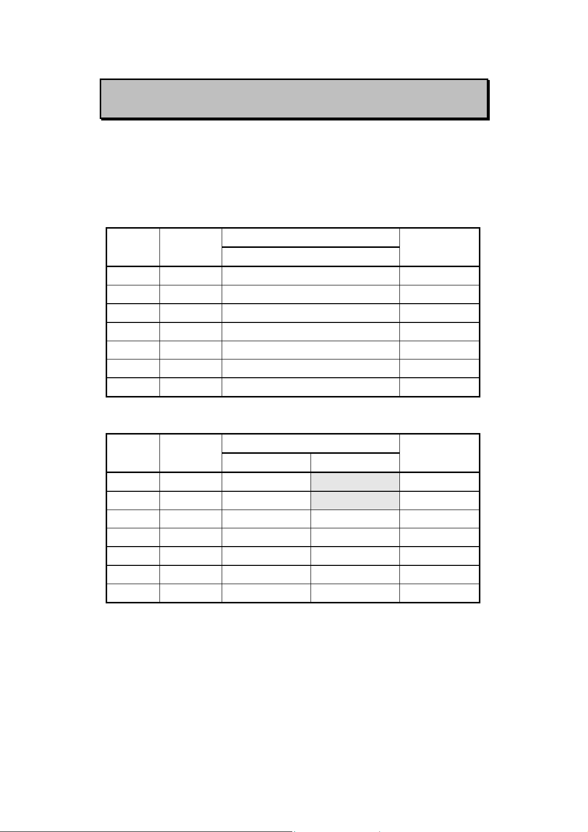
ELECTRICAL SPECIFICATION
Accuracy is expressed as: ± (% of reading + no. of least significant
digits) at 23℃± 5℃and <75% R.H.
Resistance (Parallel mode)
Test Frequency: 100 / 120 Hz
Range Maximum
Display
10MΩ 9.999MΩ
2000KΩ 1999.9KΩ
200KΩ 199.99KΩ
20KΩ 19.999KΩ
2000Ω 1999.9Ω
200Ω 199.99Ω
20Ω 19.999Ω
Test Frequency: 1K / 10K Hz
Range Maximum
Display
10 MΩ 9.999MΩ
2000 KΩ 1999.9KΩ
200 KΩ 199.99KΩ
@1K Hz @10KHz
0.6%+5
0.3%+5
0.3%+2 0.6%+5 -
Accuracy
Specified Note
100 Hz/ 120Hz
0.6%+5 After open cal.
0.3%+3 After open cal.
0.3%+2 -
0.3%+2 -
0.3%+2 -
0.5%+3 After short cal.
0.6%+40 After short cal.
Accuracy
2.5%+10
0.8%+10
Specified Note
After open cal.
*N2
After open cal.
*N2
20 KΩ 19.999KΩ
2000 Ω 1999.9 Ω
200 Ω 199.99 Ω
20 Ω 19.999 Ω
0.3%+2 0.6%+5 -
0.3%+2 0.6%+5 -
0.5%+3 1.2%+25 After short cal.
0.6%+40 1.2%+200 After short cal.
Note:
1. DUT (Device Under Test) & test lead should be used under
properly shielding condition.
2. The accuracy is specified for parallel mode in these ranges.
11
Page 12
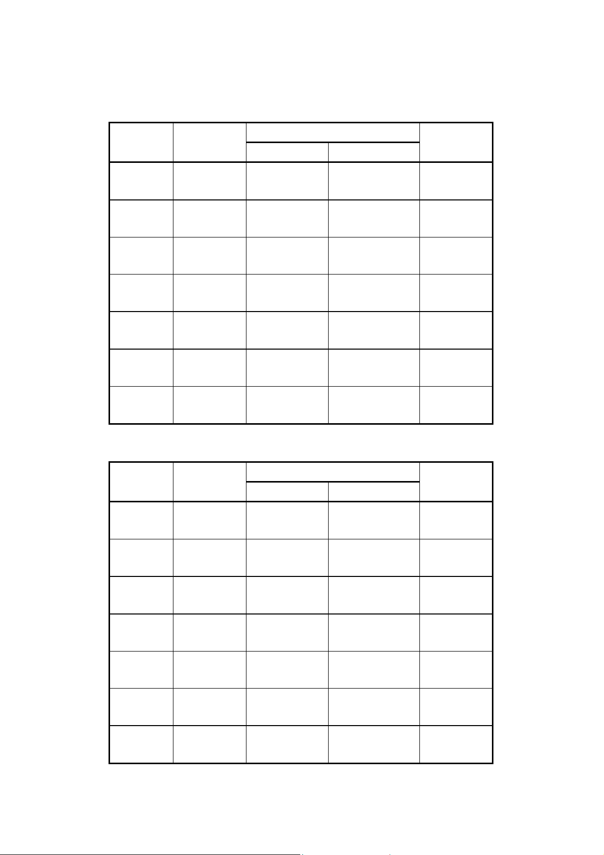
Capacitance (Parallel mode)
Test Frequency: 100 / 120 Hz
Accuracy Range Maximum
Display
10mF 19.99mF
*N4
1000μF 1999.9μF
*N5
200μF 199.99μF
Capacitance DF
2.5%+5
(DF<0.1)
0.6%+5
(DF<0.1)
0.4%+3
DF<0.5
20μF 19.999μF
0.4%+3
(DF<0.5)
2000nF 1999.9nF 0.4%+3
(DF<0.5)
200nF 199.99nF 0.4%+5
(DF<0.5)
20nF 19.999nF 0.6%+5
(DF<0.1)
5%+100/Cx+5
(DF<0.1)
1%+100/Cx+5
(DF<0.1)
0.4%+100/Cx+5
(DF<0.5)
0.4%+100/Cx+5
(DF<0.5)
0.4%+100/Cx+5
(DF<0.5)
0.4%+100/Cx+5
(DF<0.5)
1%+100/Cx+5
(DF<0.1)
Spec. Note
After short
cal.
After short
cal.
-
-
-
After open
cal.
After open
cal.
Test Frequency: 1 KHz
Range Maximum
Display
1mF 1.999mF
*N4
200μF 199.99μF
Capacitance DF
2.5%+5
(DF<0.1)
0.6%+5
(DF<0.1)
20μF 19.999μF
0.4%+3
(DF<0.5)
2000nF 1999.9nF 0.4%+3
(DF<0.5)
200nF 199.99nF 0.4%+3
(DF<0.5)
20nF 19.999nF 0.4%+5
(DF<0.5)
Accuracy
5%+100/Cx+5
(DF<0.1)
1.2%+100/Cx+5
(DF<0.1)
0.4%+100/Cx+5
(DF<0.5)
0.4%+100/Cx+5
(DF<0.5)
0.4%+100/Cx+5
(DF<0.5)
0.4%+100/Cx+5
(DF<0.5)
Spec. Note
After short
cal.
After short
cal.
-
-
-
After open
cal.
2000pF 1999.9pF 0.6%+5
(DF<0.1)
1.0%+100/Cx+5
(DF<0.1)
After open
cal.
12
Page 13
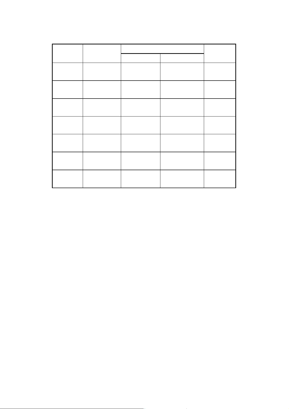
Test Frequency: 10 KHz
Accuracy Range Maximum
Display
50μF 50.0μF
20μF 19.999μF
2000nF 1999.9nF 1.0%+5
200nF 199.99nF 1.0%+5
20nF 19.999nF 1.0%+5
2000pF 1999.9pF 1.2%+6
200pF 199.99pF 2.0%+8
Capacitance DF
2.0%+10
(DF<0.1)
2.0%+6
(DF<0.2)
(DF<0.5)
(DF<0.5)
(DF<0.5)
(DF<0.5)
(DF<0.1)
8%+100/Cx+10
(DF<0.1)
3.0+100/Cx+8
(DF<0.2)
1.0%+100/Cx+6
(DF<0.5)
1.0%+100/Cx+6
(DF<0.5)
1.0%+100/Cx+6
(DF<0.5)
2.0%+100/Cx+6
(DF<0.5)
4.0%+100/Cx+8
(DF<0.1)
Spec. Note
After short
cal.
After short
cal.
-
-
-
After open
cal.
After open
cal.
Notes:
1. Q Value is the reciprocal of DF.
2. DUT (Device Under Test) & test lead should be used under properly
shielding condition.
3. Cx=Counts of displayed C value, e.g. C=88.88μF then Cx=8888.
4. This reading can be extended to 1999 MAX display with accuracy
not specified.
5. This reading can be extended to 19999 MAX display with accuracy
not specified.
6.
The accuracy for ceramic capacitor will be influenced depending on
the dielectric constant (K) of the material used to make the ceramic
capacitor. Related influence factors, please refer to the chapter
“Component dependency factors” on the accompanying CD-ROM.
13
Page 14
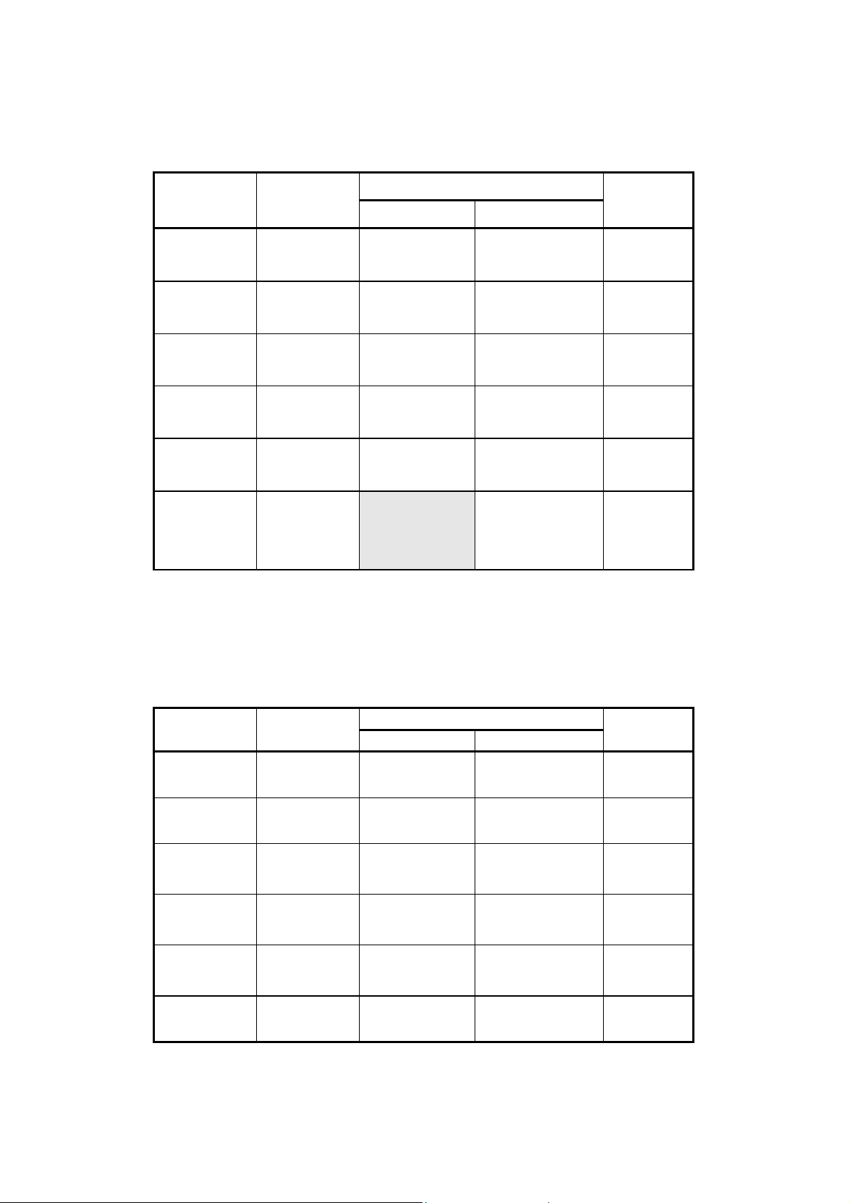
Inductance (Series mode)
Test Frequency: 100 / 120Hz
Accuracy (DF<0.5) Range Maximum
Display
Inductance DF
1000H 999.9H 0.3%+(Lx
/10000) %+5
200H
199.99H 0.3%+(Lx
*N1
1%+100/Lx+5 After open
0.8%+100/Lx+5 -
Spec. Note
cal.
/10000)%+5
20H
19.999H 0.3%+(Lx
*N1
0.8%+100/Lx+5 -
/10000)%+5
2000mH
1999.9mH 0.3%+(Lx
*N1
0.8%+100/Lx+5 -
/10000)%+5
200mH 199.99mH 0.8%+(Lx
/10000)%+5
20mH 19.999mH 1.0%+(Lx
/10000)%+5
1.5%+100/Lx+5 After short
cal.
5%+100/Lx+5 After short
cal.
*N2
Notes:
1. For lower than 10% of rang e, ad di ti onal 10 digits should be ad ded to
the accuracy.
2. The accuracy is specified for series mode in this range.
Test Frequency: 1 KHz
Range
Maximum
Display
Accuracy (DF<0.5)
Inductance DF
100H 99.99H 0.3%+(Lx
/10000) %+5
20H 19.999H 0.3%+(Lx
/10000)%+5
2000mH 1999.9mH 0.3%+(Lx
/10000)%+5
200mH 199.99mH 0.3%+(Lx
/10000)%+5
20mH 19.999mH 0.5%+(Lx
/10000)%+5
2000µH 1999.9µH
1.0%+(Lx
/10000)%+5
Spec. Note
1.0%+100/Lx+5 After open
cal.
0.8%+100/Lx+5 -
0.8%+100/Lx+5 -
0.8%+100/Lx+5 -
2.5%+100/Lx+5 After short
cal.
5%+100/Lx+5 After short
cal.
14
Page 15
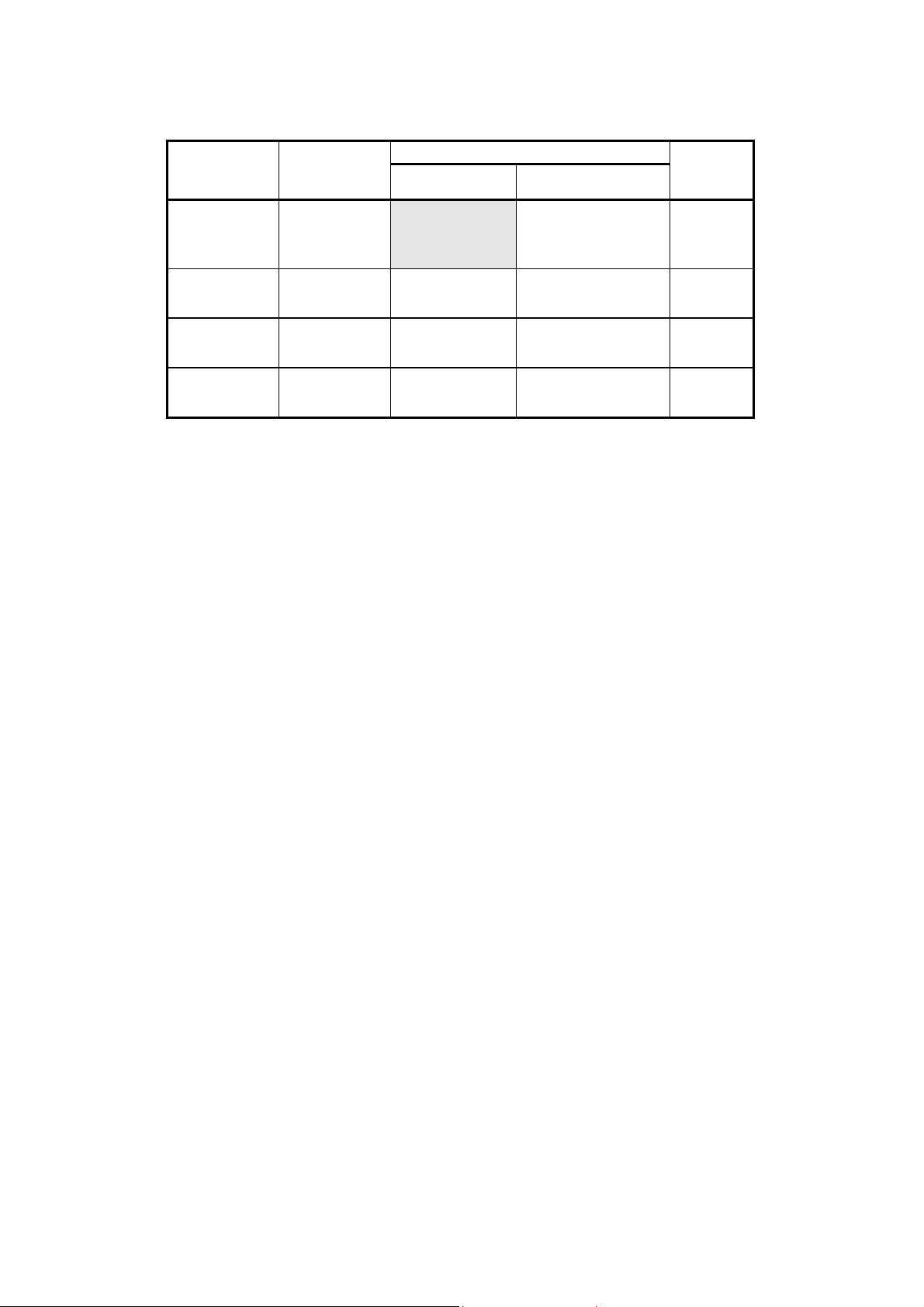
Test Frequency: 10 KHz
Maximum
Range
Display
Accuracy (DF<0.5)
Inductance DF
Spec.
Note
1000mH 999.9mH 2.0%+(Lx
1.5%+100/Lx+10 -
/10000)%+ 8
*N4
200mH 199.99mH 0.6%+(Lx
1.5%+100/Lx+10 -
/10000)%+8
20mH 19.999mH 0.6%+(Lx
2.0%+100/Lx+15 -
/10000)%+10
2000µH 1999.9µH
1.0%+(Lx
/10000)%+10
5.0%+100/Lx+20 After
short cal.
Notes:
1. Q Value is the reciprocal of DF.
2. This specification is based on the measurement performed by
specified test leads.
Lx=counts of displayed L value, e.g. L=88.88H, then Lx=8888.
3.
4. The accuracy is specified for series mode in this range.
15
Page 16
MAINTENANCE
WARNING
To avoid electrical shock, do not perform any service
unless you are qualified to do so.
Service
If the instrument fails to operate, to check line-power, power cord, fuses
and test leads, and replaces them if necessary. If the instrument still
can’t work, double check operating procedure as described in this
instruction manual. When servicing, use specified replacement parts
only. The meter must be completely turned off while replacing the fuse.
WARNING
To avoid electrical shock or damaging the meter, never
get water inside the case.
Cleaning the Meter
Before cleaning this meter, make sure the power is
switched to OFF position and the power cord has been
removed. To clean the meter, wipe the dirty parts with
gauze or soft cloth soaked with diluted neutral detergent.
Do not get too wet to prevent the detergent from
penetrating into inside parts and causing damages. After
cleaning, make sure the instrument is dried completely
before using.
16
 Loading...