


COMBI ν LINE
Blood-Gas-Electrolyte-Metabolite Analyser
For In-Vitro-Diagnostic Use
Instruction Manual
 Eschweiler GmbH & Co. KG
Development - Manufacturing - Sales - Technical Service
Made in Germany
Instruction Manual
ManualVersion
The latest Manual version is: 4.01
Order No.: 40 8 90 11 Print: IM-401 combiline 2_2010.PDF
Copyright © 2010 by
Eschweiler GmbH & Co. KG, Holzkoppelweg 35, 24118 Kiel
No part of this Manual may be reproduced in any form without the written permission of Eschweiler GmbH & Co. KG.
Manual History
Manual |
ANALYSER-Software |
Revision |
Version |
Version |
Date |
|
|
|
4.01 |
2500 |
April 2010 |
Software Copyrights
The software for the combiLINE Analyser is the User and Instrument Control Software for the combiLINE. The combiLINE Software is the intellectual property of Eschweiler GmbH & Co. KG hereafter Eschweiler.
Intellectual property rights shall remain with Eschweiler.
You are entitled to use the combiLINE Software and the printed accompanying material at your place of work only.
Any violations of property rights or copyright or trademark or conditions of use may be subject to legal action.
Manufacturer
Eschweiler GmbH & Co. KG
Holzkoppelweg 35
24118 Kiel, Germany
Phone: |
-49- 431-54 65 80 |
FAX: |
-49- 431-54 94 23 |
Internet: http://www.eschweiler-kiel.de
E-Mail: info@eschweiler-kiel.de
Instruction Manual

Consumable solutions and spare parts from other manufacturers used in ESCHWEILER Analysers.
We point out specifically that fault-free operation of our analysers can be guaranteed only when original ESCHWEILER solutions and spare parts are
used.
The name ESCHWEILER with its decades of experience in the field of blood
gas analysis also stands for the quality of the spare parts and consumable solutions. ESCHWEILER sensors and solutions form a functional unit
whosecomponentsareoptimallyadaptedtoeachother.Measuringaccuracy and long life of the sensors are the goal of this system.
Through intensive development work, the chemical compositions of our solutions have been adjusted optimally to the ESCHWEILER sensors and
guarantee, besides precise measurements, the greatest possible protection of the sensitive sensor surfaces.
For example, special wetting solutions are used which have a decisive influence on the unconstrained contact between sensor and solution in the measuring capillary. At the same time suitable preservatives prevent the
growth of micro-organisms in the consumable solutions and keep them from being introduced into the measuring capillaries of the ESCHWEILER
analysers.
The characteristics and concentrations of both the wettingand the preservative substances are selected according to the special requirements of our sensors.
Fault-free operation of our analysers with measuring accuracy and long
sensor life are the main goals of our quality requirements. Only if
ESCHWEILER original parts and solutions are used we can meet these requirements.
Please support us in doing this!
Instruction Manual

Contents
COMBI ν LINE
Contents
! Safety Issues.............................................. |
5 |
|
! 1 |
Hazards and Precautions ................................................. |
5 |
! 2 |
Maintenance and Hygiene ................................................ |
7 |
! 3 |
First-Aid Measures ........................................................... |
8 |
! 4 |
Repairs .............................................................................. |
8 |
1 Introduction ................................................ |
9 |
||
1.1 |
Intended Use ..................................................................... |
9 |
|
1.2 |
System Description .......................................................... |
9 |
|
|
1.2.1 |
System Overview and Terms .............................. |
10 |
|
1.2.2 |
Functional Description ........................................ |
21 |
|
1.2.3 |
Specimen Collection .......................................... |
22 |
|
1.2.4 |
Storage of Standard Data ................................... |
24 |
|
1.2.5 |
Software Overview ............................................. |
25 |
1.3 |
Power Up Procedure ...................................................... |
26 |
|
2 Installation Procedure............................. |
29 |
|
2.1 |
Unpacking ....................................................................... |
29 |
2.2 |
Operating Conditions ..................................................... |
30 |
2.3 |
Installation Process ....................................................... |
30 |
2.4 |
Transport of the Combiline ............................................ |
34 |
2.5 |
Storage of the Combiline ............................................... |
34 |
3 Measurement and Special Functions |
... 36 |
||
3.1 |
Using Syringe or Capillary ............................................ |
37 |
|
|
3.1.1 Display and Print Results ................................... |
40 |
|
3.2 |
Accessories for capillaries ............................................ |
41 |
|
3.3 |
Quality ControlTest ........................................................ |
42 |
|
3.4 |
Respiration Gas .............................................................. |
44 |
|
|
3.4.1 Urine Measurement ................................................. |
45 |
|
3.5 |
Operation Menus ............................................................ |
46 |
|
|
3.5.1 |
OPERATION Menu ............................................ |
47 |
|
3.5.1.1 |
Rinse ............................................................ |
47 |
|
3.5.1.2 |
Calibration ..................................................... |
47 |
|
3.5.1.3 |
Calibration with BGA-Solution ....................... |
49 |
|
3.5.1.4 |
Calibration with ISE-Solution ........................ |
49 |
|
3.5.1.5 |
Activation of Hb-Sensor ................................ |
50 |
|
3.5.1.6 |
Sensor Parameter ......................................... |
53 |
|
3.5.1.7 |
Economy Mode ............................................. |
55 |
|
3.5.2 |
SERVICE - TEST Menu ..................................... |
56 |
|
3.5.2.1 |
Test pCO2-Sensor voltage / BGA 3 ............... |
56 |
|
3.5.2.2 |
Test pCO2-Sensor voltage / BGA 4 ............... |
56 |
|
3.5.2.3 |
Test pH-/ISE-Sensor Voltage/ CAL3 .............. |
57 |
|
3.5.2.4 |
Test pH-/ISE-Sensor Volt./ISE CAL4+M ........ |
57 |
|
3.5.2.5 |
Test O2-SensorVoltage/Gas ......................... |
57 |
|
|
||
combiLINE - Instruction Manual - Version 4.01 |
Page1 |
||

Contents
COMBI ν LINE
3.5.2.6 |
Test Air Pressure and Temperature ................ |
58 |
3.5.2.7 |
Test Light Barriers ......................................... |
59 |
3.5.2.8 |
Protein Removal ........................................... |
60 |
3.5.2.9 |
Reagent Test (Test of Liquid Transport) .......... |
61 |
3.5.3 |
STANDARD DATA Menu ..................................... |
62 |
3.5.3.1 |
Calibration Data ............................................ |
62 |
3.5.3.2 |
Date and Time ............................................... |
63 |
3.5.3.3 |
Correlation .................................................... |
64 |
3.5.3.4 |
Settings ........................................................ |
65 |
3.5.3.5 |
Sensor Selection ........................................... |
66 |
3.5.3.6 |
AB-Parameter Selection ................................ |
67 |
3.7 Replacements ................................................................. |
68 |
|
3.7.1 |
Calibration Solution ............................................ |
68 |
3.7.2 |
Wash Solution .................................................... |
68 |
3.7.2.1 |
CAL3 / CAL 4 ..................................................... |
69 |
3.7.3 |
Waste Solution ................................................... |
69 |
3.7.4 |
Printer Paper ...................................................... |
70 |
4 Error Messages ....................................... |
71 |
|
4.1 |
Error Eleminations ......................................................... |
71 |
4.2 |
Error Indications ............................................................ |
71 |
4.3 |
pCO2-Slope Error ........................................................... |
73 |
4.4 |
pO2-Slope Error ............................................................. |
74 |
4.5 |
pH-Slope Error ............................................................... |
75 |
4.6 |
ISE-Slope Error .............................................................. |
76 |
5 Explanation of Testparameter ................ |
77 |
|
5.1 |
EnteredValues ................................................................ |
77 |
5.2 |
Measured Parameters .................................................... |
78 |
5.3 |
Calculated Parameter ..................................................... |
79 |
|
6 Maintenance ............................................. |
81 |
||
|
6.1 |
Maintenance Schedule ................................................... |
81 |
|
|
6.2 |
Maintenance of Sensors ................................................ |
83 |
|
|
|
6.2.1 |
Removal of Sensors ........................................... |
84 |
|
|
6.2.2 |
Installation of Sensors ....................................... |
85 |
|
|
6.2.3 |
Principle of pH-measurement ............................. |
87 |
|
|
6.2.3.1 |
Regeneration of the pH-Sensor .......................... |
89 |
|
|
6.2.4 |
Principle of pCO2-measurement ......................... |
92 |
|
|
6.2.4.1 |
Regeneration of the pCO2-Sensor ................. |
93 |
|
|
6.2.5 |
Principle of pO2-measurement ........................... |
97 |
|
|
6.2.5.1 |
Regeneration of the pO2-Sensor ................... |
98 |
|
|
6.2.6 |
Principle of K+ -measurement ........................... |
102 |
|
|
6.2.6.1 |
Exchange of the ISE-Sensor Membrane Shell103 |
|
|
|
6.2.7 |
Principle of the Na+-measurement .................... |
105 |
|
|
6.2.8 |
Principle of Ca++-measurement ........................ |
106 |
|
|
6.2.9 |
Principle of Cl- -measurement ........................... |
107 |
|
|
6.2.10 |
Principle of Li+ -measurement ........................... |
108 |
|
|
6.2.11 |
Reference Sensor ............................................. |
109 |
|
|
6.2.13 |
Metabolite sensors ............................................ |
112 |
|
|
|
||
Page 2 |
combiLINE - Instruction Manual - Version 4.01 |
|
||

Contents
COMBI ν LINE
|
6.3 |
Moisture Absorber......................................................... |
113 |
|
6.4 |
Fuse Replacement ......................................................... |
114 |
|
6.5 |
Replacement of Fan Filter ............................................. |
114 |
|
6.6 |
Replacement of Roller Pump Tubes ............................. |
115 |
|
6.7 |
Replacement of Sample-Port-Adapter .......................... |
116 |
|
6.8 |
Disposal of the Combiline ............................................ |
116 |
7 |
APPENDIX .............................................. |
119 |
|
|
7.1 |
List of Consumables ..................................................... |
119 |
|
7.2 |
List of Spare Parts......................................................... |
121 |
|
7.3 |
Specifications for Safety ............................................... |
123 |
|
7.4 |
Declaration of Conformity ............................................. |
124 |
|
7.5 |
Technical Specifications ............................................... |
125 |
|
7.6 |
Materials Provided with the Combiline ........................ |
127 |
|
7.7 |
Interface Description ..................................................... |
129 |
|
7.8 |
Reference Literature ...................................................... |
129 |
8 |
Index........................................................ |
130 |
|
combiLINE - Instruction Manual - Version 4.01 |
Page3 |

Contents
COMBI ν LINE
Page 4 |
combiLINE - Instruction Manual - Version 4.01 |
Safety Issues
COMBI ν LINE
! Safety Issues
Please read the Instruction Manual in its entirety prior to operating the Combiline. In order to ensure a high level of performance, all warnings
and references to technical safety in this Instruction Manual have to be followed.
!1 Hazards and Precautions
DANGER
CAUTION
Biohazard
NOTE
The cautions and safety regulations in this Instruction Manual meet international classifications:
Warns of a risk of injury or of a risk to life (for example by electrical shock).
Warns of a risk of injury or of the analyser being severely damaged.
Warns of a risk of biological material like blood or other human or animal specimen. Risk of infection! Potential infectious area/material!
Introduces rules to be observed.
Electrical safety
DANGER
The following safety issues have to be observed at all times:
-Check that the operating voltage is set correctly before you connect the device to the main power supply.
-To connect the analyser to the main power supply, use only sockets which are grounded to avoid the risk of an electrical shock.
-Use only grounded extension power cords. The used power cord has to correspond to the country specific regulations.
-Never intentionally disconnect the grounding contacts.
There is the risk of electrical shock if the protective conductor is interrupted within or outside the analyser, and/or the grounded contacts have been disconnected from the line.
-Never remove protective guards or secured components since you could expose electrically live parts in this way.
-Electrical connection contacts (plugs, sockets, etc.) can be electrically live.
combiLINE - Instruction Manual - Version 4.01 |
Page5 |

Safety Issues
COMBI ν LINE
-Even after an analyser has been switched off, components (e.g. capacitors) can be under voltage as the result of an electrical charge.
-All current carrying parts are sources of danger for an electrical shock.
-Surfaces (floors, work tables) have not to be moist when you are working with any electrical device.
-Carry out only the maintenance work and/or the replacement of parts described in these Instruction Manual.
-Unauthorized work on the analyser can lead to the guarantee obligation becoming null and void with necessary expensive service work to correct it.
-All work, which requires the analyser to be opened, have to be carried out by an authorised technician who is familiar with the risks related thereto.
-Use only replacement fuses of the stated type and with the stated nominal current. Never use fuses, which have been “repaired”.
-There is a Lithium battery on MAIN BOARD that have to be replaced by the authorised technical service every 5 years! In case of a battery fault, all memorised parameter might be lost.
Mechanical Safety(Analyser is operating)
CAUTION
Biological Material - Risk of
Infection
Biohazard
-Never open or unscrew analyser's casing parts while it is switched
ON. There is a risk of injury due to moving parts as fans, pumps, stepper-motors or any other mechanical movements.
-Wear gloves in all cases if there is a risk of infection.
-Avoid any direct contact with samples that are potentially infectious or which may generate other risks to the human body (Aids, Hepatitis etc). In case of direct body contact go and wash the contaminated area immediately. Use a suitable skin disinfection solution. Ask your doctor for aid.
-If sample material (blood) or reagent is spilled onto the analyser, wipe it off immediately and refer to the chapter ! 2 Maintenance and Hygiene.
-Do not open a waste bottle as long as the analyser is in process.
Page 6 |
combiLINE - Instruction Manual - Version 4.01 |
Safety Issues
COMBI ν LINE
Reagents and Controls
- Observe the suggestions in the package inserts for an exact use of
the reagents and quality controls. Note that reagents and quality con-
trol material can be biological material!
CAUTION
-Don't use Reagents, Controls and other Liquids after expiration date!
-Avoid any liquid penetration into the analyser.
Restrictions for Samples, Reagents and Controls
- For consumables no guarantee can be provided for any resistance against organic solvents. For this reason, do not use any organic sol-
vents unless such solvents are expressly indicated.
CAUTION
-Do not use any other rinsing or cleaning solutions as recommended by the manufacturer or representative.
-Waste liquid has to be disposed in compliance with the legislation.
Accuracy and Precision of the
Measured Results
CAUTION
Fire and Explosion Hazards
CAUTION
Operator Qualification
-In order to ensure a flawless operation of the analyser measure control samples and watch the function of the analyser closely.
-Faulty measurement results may result in an incorrect diagnosis or range danger for patient.
-Do not place any flammable or hazardous explosive material in the proximity of the device. Electrical sparks could cause fire or explosions.
-The analyser should only be operated by trained personnel. Improper operation of the analyser might cause inaccurate measuring results!
!2 Maintenance and Hygiene
CAUTION
-No organic acid based cleaning substances should be applied. In-
stead use cleaner designed for cleaning and disinfecting laboratory analysers. Only use a dampened cloth to clean the analyser.
-Never spray or pour cleaning solution directly onto the analyser, that may negatively impact the analyser’s functions significantly.
-Keep the analyser clean and do not spill liquids onto it.
-In case liquids were spilled onto the analyser, immediately absorb liquid with a suitable cloth.
-Contact your distributor if your control measurements do not produce the expected results.
combiLINE - Instruction Manual - Version 4.01 |
Page7 |

Safety Issues
COMBI ν LINE
Recommended Disinfectant Solutions.
A suitable disinfectant is available by BODE Chemie, Hamburg:
Bacillol®, is recommended for areas at risk of infection, where rapid contact times and drying times are necessary.
BODE Chemie GmbH & Co
Melachtonstr.27 - 22525 Hamburg, Germany
Phone:+49- (0)40-54 00 60 - Internet:www.bode-chemie.de
Another suitable disinfectant is available by S&M Schülke & Mayr:
TERRALIN® Liquid
Schülke & Mayr GmbH
Robert-Koch-Str.2 - 22851 Norderstedt, Germany
Phone: + 49- (0)40-521 00-0 - Internet:www.schuelke-mayr.com
See the website for your nearest representation. Ask for an EC Material
Safety Data Sheet according to EC 91/155.
! 3 First-Aid Measures
If a person swallowed any chemical solution may be while servicing,
wash out mouth with water.
If provided person is unconscious, than call a physician.
If inhaled, remove to fresh air. If breathing becomes difficult, than call a physician.
In case of contact, immediately wash skin with soap and copious amount of water.
In case of contact with eyes, flush with copious amounts of water for at least 15 minutes.
Assure adequate flushing by separating the eyelids with fingers, than call a physician.
! 4 Repairs
CAUTION
Useful hint
NOTE
-Repairs to the analyser may only be carried out by trained personnel, and replacement parts have to comply with the analyser specifications.
-In case of analyser problems contact your representative.
In this Manual a bullet "•" draws your attention to an instruction. Example:
• Press enter-key to confirm ...
Page 8 |
combiLINE - Instruction Manual - Version 4.01 |

Introduction
COMBI ν LINE
1 Introduction
1.1 Intended Use
IVD
1.2 System Description
Functions
Operation
Generals
The ESCHWEILER Combiline is a microprocessor-controlled automatic analysis system for quantitative measurement and calculation of pH-, electrolyte-, haemoglobinblood gasand metabolite parameter of a single sample of human whole blood or serum.
The Combiline is intended for use by trained operators in hospital labs and/or specialist doctor's offices for in-vitro-diagnostics.
The samples are inserted directly into the Sample-Port from capillary tubes, syringes, vacutainers or other sample-intake systems.
The material to be measured, is automatically sucked into the analysis system from capillaries and is injected from syringes, into which can be seen from outside window.
The sample quantity needed, to fill the analyser system completely, is controlled by a Light Barrier.The sample volume is approx. 50-150µl depending on the model type.
The analysis system consists of individually replaceable Sensor modules. The thermostating at 37.0°C ± 0,2 is done by a solid-state thermostat and is not software controlled (refer to chapter 3.5.2.6).
The calibration of the Sensors is fully automatic or can be carried out manually.
Sampleand calibration waste is collected in a disposable Waste Bottle with a filling level control. Empty Wash Solution Bottles are used as
Waste Bottles.
The Combiline is operated with the help of a menu-controlled dialogue by Soft-keys and a 16-line LCD display. By this Keypad inputs such as changes in the standards (Hb, FIO2 and RQ), the calibration parameter or the date and time can be made.
In the SERVICE menu / REAGENTTEST the individual functions are carried out as long as the corresponding key is pressed.
If a Calibration Solution Bag or Bottle is empty, this is shown in the display. After a new bag or bottle has been replaced and the QUIT-key has been pressed, the analysis system is ventilated automatically. The
Combiline is then ready for use again.
If the Waste Bottle is full, this is also indicated. After the Waste Bottle has been replaced, the Combiline is ready to measure again.
At all times the Combiline remains switched ON and is continuously calibrated in a programmed cycle. In times of reduced sample activity, for example at night, the Combiline can be operated in an Economy mode with extended calibration cycle times.
combiLINE - Instruction Manual - Version 4.01 |
Page9 |

Introduction
COMBI ν LINE
All Sensors can be switched ON or OFF individually by the user as needed.
The system remains ready for operation. It is also possible to select the computed values which are to be expressed individually.
Maintenance
Several easily operated testand function programs are available for the user, which make it possible to localize functional disturbances quickly. The operability of the Combiline and the Sensors is monitored automatically and continuously. Irregularities, for example in the function of the Sensors or the supply with working materials, are indicated at once.
1.2.1System Overview and Terms
The Combiline
Dialogue Area consists of:
LCD-Display and Keypad
Built-in Printer
Support Area consists of:
Washand Waste Solution Bottle
Combiline BGA: Waste Bottle, BGA1, BGA2, WASH1
Combiline ISE: Waste Bottle, CAL3, CAL4+M, WASH2
Combiline BGA+E: Waste Bottle, WASH2, BGA3, BGA4, CAL3, CAL4
Combiline meta: Waste Bottle, WASH2+M, BGA3, BGA4, CAL3,
CAL4+M
Analysis Area consists of:
Sample Port
Sensor Array, thermostated at 37.0°C
Figure 1 Combiline, front view
Dialogue Area
|
Headline |
|
|
|
|
|
|
|
|
|
|
|
|
|
Display of: |
Display of |
|
|
|
|
|
|
|
|
|
||
|
|
|
|
|||
|
- Menus, |
|
|
|||
|
Functions |
|
|
|
|
|
|
- Information |
|
|
|||
|
|
|
|
|
||
|
|
|
|
|
|
|
|
- Parameter |
|
|
|
|
|
|
|
|
|
|
||
|
|
|
|
|
|
|
|
Feetline |
|
|
|
|
|
|
|
|
|
|
|
|
|
|
|
|
|
|
|
Figure 2 Dialogue Area
Page 10 |
combiLINE - Instruction Manual - Version 4.01 |

Introduction
COMBI ν LINE
LCD Display
Software dialogues are shown by the 16 line (30 characters each) LCD Display which is back-lighted. The contrast is adjusted by the manufacturer and can be readjusted by the Technical Service only.
The software dialogue appears in four sections on the display.
The headline (upper section) indicates the analyser status and actions e.g.: STAND BY, WARM UP PHASE, CALIBRATION DATA etc.
In the middle section, between headline and feetline the software indicates Software menus, measured results, system parameter etc.
The feetline (lower section) indicates the system time on the left side (e.g.: 14:27) and the timer countdown for the next automatic system calibration (e.g.: CAL 25 min) on the right side.
The right section indicates functions to be carried out by pressing the corresponding right hand Soft-Key like e.g.: OPERATION, START CALIBRATION, QUIT etc.
Keypad
numerical keys 0 - 9
decimal point key clear data key ENTER key
Figure 3 Keypad
With the numerical keys all number entries can be made in dialogues, except during measurement.
For example:
-sample identification number.
-FIO2- and RQ-values.
-values for configuration of the analyser, such as calibration parameter or time and date.
Decimal point key
With this key commas and decimal points required for numerical entries can be entered.
Clear data key
With the correction key "C", numbers entered in an activated menu can be deleted. This makes a new entry possible without opening the dialogue again.
Built-in Printer
The built-in printer and its thermal paper (56 mm wide) are located on upper side of the Combiline.
A red stripe on the left side of a print-out indicates that the paper supply is only sufficient for a few more print-outs. For paper replacement refer to chapter 3.7.4, for technical details refer to chapter 7.5
combiLINE - Instruction Manual - Version 4.01 |
Page11 |

Introduction
COMBI ν LINE
Beeper
A sound is heard by a beeper:
-after switching the power ON
-after specimen is detected by a light barrier
-to remove a syringe or capillary from Sample Port
Analysis Area
The white cover can be taken down to access the analytic parts.
Regulator for Display Contrast
Sensor Array
Valve Array. Window for the visual control of liquid flow.
Roller Pump 1
Roller Pump 2 (for Metabolites)
Figure 4 Analysis Area
Sample Port
The Sample Port is designed for the use of syringes, capillary tubes, vacutainers or other sample-intake systems.
It is equipped with a tube for washing or cleaning purposes.
Page 12 |
combiLINE - Instruction Manual - Version 4.01 |

Introduction
COMBI ν LINE
Sample introduction by a capillary
To start a measurement of a capillary sample, press MEASURE key and follow the display dialogue.
Insert capillary into the Sample Port until a resistant is given. The capillary is automatically guided to the analysis system (metal canula). After pressing the ENTER key, the sample is aspirated automatically from the capillary.
Figure 5 Sample Port and sample introduction
Sample introduction by a syringe
To start a measurement of a syringe sample, press MEASURE key and
follow the display dialogue.
Insert syringe into the Sample Port and inject sample material slowly into the Port until you hear a beep-sound. Remove the sy-
ringe from the sample port after the second beep-sound.
Before introducing a syringe into the Sample-Port, make sure that the syringe is filled completely and without air-bubbles!
NOTE
Sensor Array
The Sensor Array is the central unit of the analysis system and is thermostated at 37.0°C ± 0.2.The Combiline can be equipped with different Sensors depending on the customer's needs.
If the analyser is equipped with a Haemoglobin-Sensor, it is installed on the left side of the array.
Release the Sensor Catch lever only for Sensor maintenance, otherwise the analysis system is open! Make sure that the analyser system is closed!
combiLINE - Instruction Manual - Version 4.01 |
Page13 |

Introduction
COMBI ν LINE
sample light barrier
sensor catch closed pos.
Figure 7 Sensor Array
Support Area
NOTE
A Sensor Catch is located beside the Ref.-Sensor whitch locks up the liquid system of the Sensor group. If any liquid is flowing through the analysis system, a back-light is on to display the liquid flow and possible sediments can be seen. For more information about the Sensors refer to chapter 6.2 Maintenance of Sensors.
The light barrier (LB2) at the end of the Sensor group controls the flow of the Calibrationand Washing solution and also the filling level of an introduced sample. (LB1 is out of function).
Example: Ca++-Sensor with exploded parts
Ca++ |
measurement |
|
capillary |
||
|
Figure 8 Calcium-Sensor (example)
The Combiline carries out Sensor calibrations automatically in a preprogrammed cycle of 90 min, but in ECONOMY mode in a cycle of 240 minutes.
To determine the relationship between the Sensor signals and the partial pressure and ISE values of samples, the Combiline uses high and low level Calibration Solutions.
For determination of Blood-Gas results, calibration solutions BGA1 and BGA2 are used in the COMBILINE BGA. For this BGA3 and BGA4 are used in the COMBILINE BGA+E and versions with metabolites. For determination of the electrolyte concentrations the calibration solutions CAL3 and CAL4 are used in COMBILINE BGA+E and COMBILINE ISE
BGA: blood gas analysis; ISE: Ions selective electrode; meta: metabolites
Calibrator Solution Bags and Wash Solution are consumables, see chapter 7.1 List of Consumables.
Page 14 |
combiLINE - Instruction Manual - Version 4.01 |

Introduction
COMBI ν LINE
Calibration Solution Bags
NOTE
The bags are connected to the analysis system by the bag's Septum to the corresponding Adaptor.Don't misplace Bags!
The Adaptor with a Slide Bar is named after the corresponding Calibration Solution Bag and is software controlled by a light barrier.
Use only ESCHWEILER Calibration Solutions for COMBILINE analysers, otherwise disturbances could appear or results could be wrong!
Refer to chapter 3.7.1 for the replacement of Calibration Solution Bags. Don't replace a Calibration Solution Bag while the COMBILINE is powered OFF!
If a Calibration Solution Bag is empty this is shown on Display.
Figure 9 Support Area COMBILINE BGA
In COMBILINE BGA the Calibration Solution Bag BGA1 serves for
determining the low Sensor signal (lower calibration point) of the pCO2 and pH.The Calibration Solution Bag BGA2 serves for determining
the high Sensor signal (upper calibration point) of the pCO2 and pH.
In COMBILINE BGA+E and all metabolite versions the Calibration Solution Bag BGA3 serves for determining the low Sensor signal (lower
calibration point) of the pCO2 .
The Calibration Solution Bag BGA4 serves for determining the high
Sensor signal (upper calibration point) of the pCO2
In COMBILINE ISE, BGA+E and all metabolite versions the Calibration
Solution Bottle CAL3 serves for determining the low Sensor signal
(lower calibration point) of the ISE and pH sensors.
In COMBILINE ISE and BGA+E the Calibration Solution Bottle CAL4 serves for determining the high Sensor signal (upper calibration point) of the ISE and pH sensors.
The calibration parameter are stored in the internal memory.
combiLINE - Instruction Manual - Version 4.01 |
Page15 |

Introduction
COMBI ν LINE
WASH2(+M) BGA3 BGA4 |
CAL4 (+M) |
||||||
Waste |
|
|
|
|
CAL3 |
||
|
|
||||||
|
|
|
|
|
|
|
|
|
|
|
|
|
|
|
|
Figure 9 and 9a Support Area Combiline BGA+E / Combiline meta
|
|
CAL3 |
CAL4+M |
CAL4 |
|
K+ |
1.80 mmol/l |
5.50 mmol/l |
5.50mmol/l |
||
Na+ |
110 mmol/l |
155 mmol/l |
150 mmol/l |
||
Ca+ |
0.50 mmol/l |
1.50 mmol/l |
1.50 mmol/l |
||
Cl- |
90 mmol/l |
130 mmol/l |
130 mmol/l |
||
Li- |
0.35 mmol/l |
2.0 mmol/l |
2.0 mmiol/l |
||
pH |
6.91 |
7.38 |
7.38 |
|
|
GLU |
|
5.00 mmol/l |
|
|
|
LAC |
|
5.00 mmol/l |
|
|
|
|
|
|
|
|
|
Table 1 Concentrations of CAL3 and CAL4 +M and CAL4
The concentrations given in table 1 for CAL3, CAL4+M and CAL4 are continually stored in the internal memory of the
NOTE Combiline.Therefore solutions with different concentrations cannot be used!
The Bag's label indicates the name of the Calibration Solution and the
- ordernumber |
- content of 130 ml |
||
- charge number |
- |
storage condition at 18-25°C |
|
- |
expiration date |
- |
standard values |
- |
CE-mark |
|
|
Consumption of Calibration Solutions
The Combiline needs for every calibration process 0.8 ml Calibration
Solution from each bag / bottle.
Page 16 |
combiLINE - Instruction Manual - Version 4.01 |
Introduction
COMBI ν LINE
Wash Solution WASH1 / WASH2
One bottle of WASH1 contains 330 ml of WASH1 Solution. One bottle of
WASH2 contains 250ml of WASH2 Solution in combiline BGA+E and 330ml of WASH2 in combiline ISE. It is absolutely necessary for cleaning the Sample Port, the analysis system and at last all tubes.
Wash SolutionWASH2+M
One bottle of WASH 2+M contains 250ml of WASH2+M Solution.
|
WASH+M is used in combiline meta only.It is absolutely necessary for |
|
cleaning the Sample Port, the analysis system and at last all tubes. |
|
|
|
Use only original ESCHWEILER Wash Solutions for |
|
Combiline analysers, otherwise disturbances could appear or |
CAUTION |
results could be wrong! |
|
|
The Wash Solution Bottle has to be replaced when the message WASH
SOLUTION/PLEASE CHECK is indicated on Display. The empty Wash Solutions Bottle must be used for the Waste Bottle replacement. For replacement of Wash Bottle refer to chapter 3.7.2.The WASH2+M SOLUTION Bottle is controlled by a level Sensor!
The bottle's label indicates the name of the solution and the
- ordernumber |
- amount |
||
- |
charge number |
- |
storage condition at 18-25°C |
- |
expiration date |
- |
CE-mark |
Consumption ofWash SolutionWASH1 andWASH2
The Combiline needs for every washing cycle 2.0ml WASH1 or WASH2
Solution.
Consumption ofWash SolutionWASH2+M
Waste Bottle
CAUTION
The Combiline needs for every washing cycle 3.0ml WASH2+M Solution.
A washing cycle will be performed automatically after every measurement.
If there is no measurement requested after 10 min of the last measurement or calibration process, the analysis system will be filled with 0.7ml
Wash Solution until the next measurement is requested or a calibration process is started automatically by the software.
The Waste Bottle adapter cap is equipped with a level Sensor. A full Waste Bottle is indicated on Display: WASTE BOTTLE / PLEASE CHECK. It is recommended to replace the full Waste Bottle with an empty Wash Solution Bottle. Refer to chapter 3.7.3 for the replacement of the Waste Bottle.
The cap must be cleaned and decontaminated regularly in accordance to the maintenance schedule!
Note that the content of theWaste Bottle is potential infectious biological material.Wear suitable GLOVES if you intended to replace theWaste Bottle to protect yourself!
Disposal of Waste Solution
Biological material has to be disposed off in accordance with the national guidelines for the disposal of biological material!
Biohazard
combiLINE - Instruction Manual - Version 4.01 |
Page17 |

COMBI ν LINE
Solution summary
designation |
amount |
order no. |
COMBILINE BGA |
|
|
WASH 1 |
330ml |
40 6 10 00 |
BGA 1 |
130ml |
40 6 10 20 |
BGA 2 |
130ml |
40 6 10 30 |
COMBILINE |
ISE |
|
WASH 2 |
330ml |
40 6 10 15 (3-4.110) |
CAL 3 |
330ml |
40 6 10 60 (3-4.100) |
CAL 4 |
330ml |
40 6 10 65 (3-4.500) |
COMBILINE BGA+E |
|
|
WASH 2 |
250ml |
40 6 10 10 |
BGA 3 |
130ml |
40 6 10 40 |
BGA 4 |
130ml |
40 6 10 50 |
CAL 3 |
150ml |
40 6 10 45 |
CAL 4 |
150ml |
40 6 10 55 |
combiLINEmeta |
|
|
WASH 2+M |
250ml |
40 6 10 11 |
BGA 3 |
130ml |
40 6 10 40 |
BGA 4 |
130ml |
40 6 10 50 |
CAL 3 |
150ml |
40 6 10 45 |
CAL 4+M |
150ml |
40 6 10 56 |
Page 18 |
combiLINE - Instruction Manual - Version 4.01 |
Introduction
COMBI ν LINE
Rear side
|
|
|
|
|
|
|
|
|
|
|
|
|
|
|
|
|
|
|
|
|
|
|
|
|
|
|
|
|
|
|
|
|
|
|
|
|
|
|
|
|
|
|
|
|
|
Mains plug |
RS232 plug |
|
|
|
|
|||
|
|
|
|
|||||||
|
Mains Fuses |
Operation LED for SD-Card |
|
|
||||||
|
|
|||||||||
Mains Switch |
SD-Card |
|
|
|
|
|
||||
|
|
|
|
|
||||||
Fan |
|
|
|
|
|
|
|
|||
|
Figure 10 Rear View |
|
|
|
|
|
|
|
||
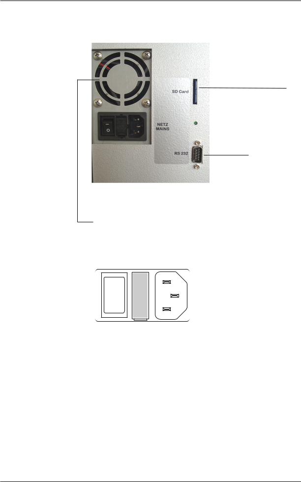
Power Connection
0 I
Figure 11 Power connector/Fuse compartment
The Power connector is located at the rear side of the Combiline and contains:
-the Power Switch ON = I/OFF = 0
-fuse compartment (for replacement refer to chapter 6.4)
-a cold device plug
combiLINE - Instruction Manual - Version 4.01 |
Page19 |

Introduction
COMBI ν LINE
Power Requirement
Note that the mains voltage must meet following requirements
The necessary operating voltage is indicated on the Type Plate.
|
Voltage |
|
Frequency |
|
Main fuses |
|
|
|
|
|
|||
|
|
|
||||
|
115 - 230V~ |
|
50/60 Hz |
|
2 x 250 V T2,5A time lag |
|
|
|
|
|
|
|
|
|
|
|
|
|
|
|
Please observe Type Plate on the rear side!
|
The Combiline has to meet the local requirements! If not, don't |
|
use it and call for the Technical Service! |
CAUTION |
|
|
|
|
The Main Cable used has to meet the local regulations (e.g. VDE, |
|
CSA-C22.2, no 21 and no 49).The cable has to be designed with |
|
NYLHY. The recommended length is 0.5 m, and the minimum |
CAUTION |
cross-section is 3 x 0,75 mm2. |
|
|
ModelType Identification
ESCHWEILER
|
|
|
combi |
|
LINE |
|
|
|
|
|
|
|
|
Type |
|
|
|
|
|
|
CL1234568-12-Hb |
No. |
CL1001 |
|
|||
|
|
|
|
|
|
|
|
|
|
|
|
|
|
AC 115V-230V~ / 50-60Hz / 70W
|
|
|
|
|
|
|
|
T 2.5A / 250V |
|
|
|
|
|
|
|
|
|
|
|
|
|
|
|
|
|
|
|
|
|
|
|
|
|
|
|
|
|
|
ESCHWEILER GmbH & Co KG, Holzkoppelweg 35, D-24118 Kiel |
|
|||||||||||
www.eschweiler-kiel.de |
|
Made in Germany |
|
|||||||||
|
Figure 12 Type Plate |
|
||||||||||
The Combiline Type Plate indicates: |
|
|||||||||||
- CE Certification |
|
|
|
- Type: Combiline xx |
||||||||
- SNo.:Combiline Serial Number |
- Volt: Operating voltage |
|||||||||||
- VA: Max. power consumption |
- Hz: Power frequency |
|||||||||||
- Manufacturer Address |
- Internet Address |
|||||||||||
Model variations |
|
|
|
|
||||||||
Combiline BGA |
= BGA (Blood-gas) |
|
||||||||||
Combiline ISE |
= ISE (Electrolytes) |
|
||||||||||
Combiline BGA+E |
= BGA + ISE |
|
||||||||||
Combiline BGA HB |
= equipped additionally with Hb-Sensor |
|||||||||||
Combiline BGA+E HB |
= equipped additionally with Hb-Sensor |
|||||||||||
Combiline meta |
= equipped additionally with metabolites |
|||||||||||
Combiline meta HB |
= equipped with metabolites and Hb-Sensor |
|||||||||||
Fan
The system is protected against overheating by two cooling fans. They are running continuously. At the rear side of the Combiline one fan is equipped with a dust filter which has to be replaced regularly, see chapter 6.5.
Page 20 |
combiLINE - Instruction Manual - Version 4.01 |

Introduction
COMBI ν LINE
RS232 Interface
The Serial interface RS232 can be used for the data transfer to the host computer. Refer to chapter 7.7 for the interface description.
Labels
A yellow label is located at the Mains Connector to indicate high voltage.
A white/blue label indicates TÜV SÜD ; i.e. the analyser is tested about safety.
1.2.2Functional Description
The Liquid System is a closed system, in which calibrations will be performed automatically in programmed cycles. Calibration Solutions, Air and Wash Solution are transported through the Sensor unit by a Pump and several Control-Valves.
The transportation of a sample and other solutions is guaranteed by an electronically controlled Roller-Pump and with help of light-barriers.
By pressing the MEASURE soft-key the system prepares for the introduction of a sample by the use of a Syringe or Capillary. Further instructions about the procedure will be shown on display.
A Capillary is coupled to the Liquid System (metal canula) automatically by the Sample Port Guide. The suck in of the sample will take
place automatically after pressing the ENTER key.
A Syringe is coupled in the same way, but the sample must be injected into the Port manually.
The measuring process is normally completed after 45-60 seconds, the results are shown automatically and are printed out.
The sample material, or in the case of a calibration the Calibration Solution, will be sucked out by a Vacuum-Pump and is guided into the Waste Bottle with the help of Control-Valves.
After a measurement, an automatic washing cycle takes place in order to clean Tubes, Sample Port and Sensor capillaries.
The Vacuum Pump produces only a low pressure, (no liquid is transported through) for the fast disposal of sample material, Washor Calibration Solution.
Moisture, that possibly reaches the Vacuum Pump, is intercepted by the Moisture-Absorber, this must be controlled regularly and emptied manually if necessary by the service stuff.
While transporting liquids, the Sensor-Array is background-illuminated in order to be able to recognize disturbances in the flow as well as sediments. Protein-sediments can cause potential-changes at the Sensors, regular maintenance-measures are therefore necessary.
combiLINE - Instruction Manual - Version 4.01 |
Page21 |

Introduction
COMBI ν LINE
1.2.3 Specimen Collection
Procuring a sample
NOTE
Use of heparin
Proper extraction and handling of blood samples before the analysis for blood gas analytical determinations are extremely important, in order to assure that the measured values received correspond to the actual (real) blood conditions.
It is recommended to contact professional workgroups in other hospitals to exchange knowledge and experience with them regularly to be up to date.
Use only heparinised sample collecting devices (syringes or capillaries)!
If the Combiline is equipped with
-Na+-Sensor, don't use Na+-heparin!
-Li+-Sensor, don't use Li+-heparin!
In these cases use ammonia-heparin with a concentration of 80 ie/ml vol. Otherwise corresponding measuring values could be wrong!
Arterial blood
Samples for pHand blood gas analysis are preferably taken from an artery. Usually the extraction is accomplished through puncture of the arteria femoralis, -brachialis or -radialis.Through catheterizing and surgical operations, however, access to other arteries is also possible.
Use of venous blood samples has found its way into clinical laboratories to some extent, but it must be kept in mind that although the material procurement is simpler in comparison to arterial puncture, venous blood can only be used when parameter of the metabolic components alone are to be determined.
Syringes
The samples are taken in airtight glassor plastic syringes. Glass syringes are used more frequently because the easy-action plunger reacts passively to the arterial pulsation of the flowing blood.
The syringe plunger must, however, be coated with paraffin oil on the sides to seal it, and then the clearance volume must be filled with heparin free of air bubbles. Other anticoagulants such as Citrat, Oxalate,
EDTA cannot be used because they shift the electrolyte values and pHvalue and thus considerably distort the acid-base parameter.When plastic syringes are used, the clearance volume must also be filled with heparin.The gas permeability of most synthetic syringes, however, represents a source of error for O2 and CO2, so that the analysis should take place immediately after extraction. The time of the analysis can be extended up to 2 hours for cooled samples.
Venous blood
When puncturing a vein, the following points must be observed: If a tourniquet is used, extraction must follow quickly, because a haemostasis causes a rise in the capillary pCO2 and a reduction of the pH. During extraction the tourniquet must not be loosened, the fist should not be closed and no pumping should take place. Since the venous blood permits only a limited statement about the acid-base household, this method has been largely replaced through the capillary technique.
Page 22 |
combiLINE - Instruction Manual - Version 4.01 |

Introduction
COMBI ν LINE
Arterialized capillary blood
Procuring of arterialized capillary blood from the periphery is relatively simple. Capillary blood, which is extracted after hyperaemia through puncture of the skin, corresponds in its composition with arterial blood, since it comes mainly from arteriols. The skin is preferably punctured in the ear lobe, in infants in the heel. The blood must flow freely and in sufficient quantity. The point of extraction should not be pinched, because this leads to the addition of blood from the venol and of tissue fluid, distorting the results.
Local hyperaemia can be achieved mechanically, thermically or chemically. Chemical hyperaemia using Finalgon salve or Rubriment oil has been proved very effective. After application, it should be allowed to react for 5-10 minutes, then rubbed off with dry tissue paper, then wiped off with 70-80% alcohol. After the puncture using a one-way stiletto, discard the first drop and catch the blood which then flows out spontaneously in heparinized capillaries, free of air bubbles.
Capillaries
Extraction is done according to the method recommended by Siggard-
Andersen.The horizontally-held capillary is introduced into the middle of the drop of blood to avoid contamination with air.The capillaries are closed after being filled and the blood thoroughly mixed with heparin. The two ends of the capillaries are closed with plastic caps, and the capillaries are then rolled between the palms of the hands. This assures an excellent mixture of blood and heparin.(See chapter 3.2)
Storage of the samples
In storing the samples it must be kept in mind that metabolism continues to take place after extraction. For the metabolism of the cells, especially the leukocytes, sour metabolites (e.g. milk acids) are formed, which alter the acid-base parameter.The degree of this acid formation depends on the number of leukocytes and especially on the temperature.
With a normal number of 5000-10.000 leukocytes/mm3 blood, analysis should take place within 15-20 minutes.Through cooling at 0-4°C the period can be extended up to 2 hours. Furthermore the pCO2 will fall because of the temperature reduction, so that the gas exchange is facilitated by the lower partial pressure slope to the atmosphere.
If, in the case of longer storage below the measuring temperature, the plasma is separated and the measurement is then carried out at a higher temperature, the results are a higher pH-value and lower gas values than in whole blood. The logical consequence is that the erythrocytes must be resuspended before warming up to measuring temperature (that is before the sample is put into the analyser).
combiLINE - Instruction Manual - Version 4.01 |
Page23 |

Introduction
COMBI ν LINE
1.2.4Storage of Standard Data
How to understand Standard Data:
Standard Data are parameter which are entered in the Menu STANDARD
DATA e.g. Calibration data, Date and Time etc.
The Standard Data of the Combiline are stored in an internal memory buffered by a Lithium-Battery. This means that the Standard Data entered by the user are saved in the memory during brief power interrup-
tions or if it is switched off manually.
Combiline was switched off for less than 8 minutes
When the Combiline is switched on again, a calibration is carried out automatically using the Standard Data, which have been entered previously.
Combiline was switched off for less than 24 hours
In this case all manually entered data are still saved in the memory. After switching on, the analyser starts the Warm-Up Phase. After that a calibration follows automatically using the Standard Data, which have been entered previously.
Combiline switched off for more than 24 hours
After power on, the analyser requires the parameter for BGA 1 / 3 and
BGA 2 / 4 by showing the Calibration Data dialogue as long as the parameter are entered.
The parameter for Hb (haemoglobin) are still saved in the memory. All previously entered Standard Data are returned to the values programmed by the factory except Date and Time. The Combiline is cali-
brated automatically after a one-hour Warm-Up Phase.Standard Data can be changed manually during the Warm-Up Phase.
Factory settings (standard-configuration)
Unit: Partial pressure = mmHg, Metabolites = mmol/l HB-Standard: 15g/dl
FIO2: 20.9% RQ: 0.85
Printouts: 1
Correlation: 1,000 (pH = 0,000) Electrodes: ACTIVE (all)
Hb-activation: Hb-sensor not active
Calibration Data pCO2/pH*: must be set by the operator!
* only for Model types with pCO2- and pH-Sensor!
Page 24 |
combiLINE - Instruction Manual - Version 4.01 |
Introduction
COMBI ν LINE
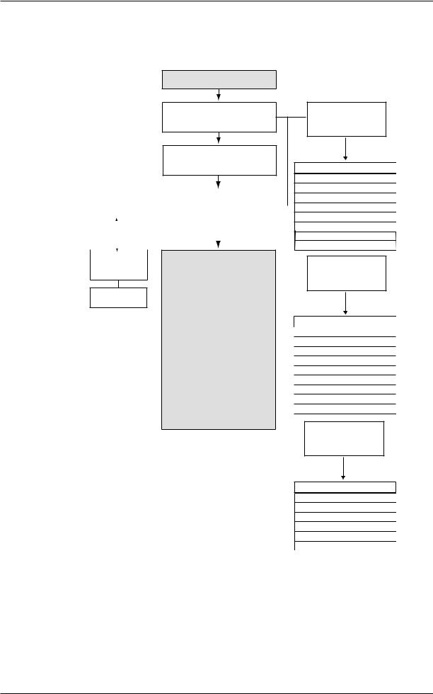
1.2.5 Software Overview
POWER UP COMBILINE
Rev. 2.500
WARM UP PHASE
OF 1 HOUR
AUTO-CALIBRATION
OF SENSORS
ECONOMY |
|
|
|
STAND BY |
|
||
PROGRAM |
|
|
|
DIALOGUE |
|
||
|
|
|
|
|
|
|
|
|
|
|
|
|
|
|
|
|
|
|
|
|
|
|
|
|
|
|
|
|
|
|
|
|
|
|
|
|
|
|
|
DISPLAY
MEASURED
MEASURING DIALOGUES
Sample introduction by selection of:
MEASURE
(SYRINGE or CAPILLARY) specify:
-BGA and meta values only
-ISE and meta values only
QC specify:
-LEVEL 1
-LEVEL 2
-LEVEL 3
-LEVEL 4
ASPIRATION GAS
Attention!
Sofware functions marked with *
are not accessible during Warming Up!
Software functions marked with ** are not available in BGA types!
Software functions marked with ***
are not available in ISE types!
Figure 13 Software Overview
press 1 x OPERATION key to select Menu
OPERATION
1 = RINSE
2 = CALIBRATION *
3 = CALIBRATION BGA * **
4 = CALIBRATION ISE * **
5 = ACTIVATION HB *
6 = SENSOR PARAMETER *
7= ECONOMY MODE *
8 = DISPLAY MEASURED
press 2 x OPERATION key to select Menu
SERVICE - TEST
1 = BGA 1 / 3 ***
2 = BGA 2 / 4 ***
3 = CAL 3 **
4 = CAL 4 **
5 = GAS ***
6 = AIR / TEMP
7 = LIGHT BARRIER
8 = PROTEIN *
9 = REAGENT TEST
press 3 x OPERATION key to select Menu
STANDARD DATA
1 = CALIBRATION DATA ***
2 = DATE / TIME
3 = CORRELATION
4 = SETTINGS
5 = SENSOR SELECTION
6 = AB-PARAMETER ***
combiLINE - Instruction Manual - Version 4.01 |
Page25 |

Introduction
COMBI ν LINE
1.3 Power Up Procedure
This chapter explains what the Combiline is doing after switching on, what dialogues appear and what functions will be performed until the STAND BY dialogue appears.
Power up the Combiline only after the installation procedure as
described in chapter 2.3.
CAUTION
Switching ON
NOTE
• Set the Power Switch on the rear in position I.
Only if the Combiline was switched off for more than 24 hours, a dialogue appears first to enter the BGA 1 / 3 + BGA 2/4 values. See chapter 1.2.4.
The following dialogue appears for about 3 seconds.
NOT READY |
RESTART |
PLEASE WAIT |
RESET |
|
|
As long as this dialogue appears you can press the corresponding softkey:
-RESTART: The analyser will warm-up. All entered parameters and all settings made are present in the memory.
-RESET: The analyser will warm-up. All parameters and all settings are reset to the manufacturer settings. The analyser demands the input of the parameter for the Calibration Solutions BGA 1 / 3 and BGA 2 / 4.
The WARM UP PHASE dialogue appears as shown below.
WARM UP PHASE |
PROGRAM |
|
PO2 |
= ACTIVE |
|
PCO2 |
= ACTIVE |
|
PH |
= ACTIVE |
|
K |
= ACTIVE |
|
NA |
= ACTIVE |
|
CA |
= ACTIVE |
|
C L |
= ACTIVE |
|
LI |
= ACTIVE |
|
GLU |
= ACTIVE |
|
LAC |
= ACTIVE |
|
HB |
= OFF |
START |
|
|
CALIBRATION |
10:45 |
AUTO 54 MIN |
|
Page 26 |
combiLINE - Instruction Manual - Version 4.01 |
 Loading...