

Escalade sports P1369 User Manual
OWNER’S MANUAL
MAJESTIC 8FT. SLATRON DROP POCKET POOL TABLE
MODEL NO. P1369
1. READ THIS MANUAL CAREFULLY BEFORE STARTING ASSEMBLY.
Read each step completely before beginning each step.
2. SOME SMALLER PARTS MAY BE SHIPPED INSIDE LARGER PARTS. CHECK INSIDE ALL PARTS
AND CARTONS BEFORE ASSEMBLING OR ORDERING PARTS.
3. USE THE HARDWARE IDENTIFIER TO IDENTIFY AND SORT ALL FASTENERS. CHECK ALL CARTONS
FOR KITS. ALL HARDWARE IS NOT LOCATED IN ONE KIT.
THIS TABLE IS CONTAINED IN FIVE SEPARATE CONTAINERS:
PLEASE DO NOT RETURN PRODUCT TO THE STORE!
Contact Escalade® Sports customer service department at:
Phone: 1-866-556-2757 Toll Free !
Fax: 1-866-873-3532Toll Free !
E-mail: pooltables@escaladesports.com
Mailing Address: Escalade® Sports, PO Box 889, Evansville, IN 47706
Please visit our World Wide Web site at:
www.escaladesports.com
On-Line Trouble Shooting Frequently Asked Questions
Technical Assistance On-Line Parts Requests
Additional Escalade® Sports Product Information
Escalade® Sports products may be manufactured and/or licensed under the following patents:
D446275
Additional patents may be pending. One or more of the listed patents and/or pending patents may cover specific product.
2L-6814-00
CAUTION
THE SPRAY ADHESIVE USED FOR APPLYING PLAYFIELD CLOTH IS EXTREMELY FLAMMABLE AND UNDER
PRESSURE
CHILDREN
AREA
To ensure safety, do not attempt to assemble system without following instructions carefully. Proper and complete assembly, use, and supervision is essential for
proper operation and to reduce the risk of accident or injury. A high probability of serious injury exists if this system is not installed, maintained, and
operate properly.
! CAREFULLY READ CAUTIONS ON SPRAY ADHESIVE CONTAINER! KEEP OUT OF THE REACH OF
! DO NOT USE OR STORE NEAR HEAT SOURCE, FLAMES, SPARKS OR WHEN SMOKING! WORK
MUST BE WELL VENTILATED. OPEN DOORS AND WINDOWS WHEN USING SPRAY ADHESIVE.
Tools Needed: (Not Included)
• Hammer (Claw Type)
• Needle Nose Pliers
• Standard Screwdriver
• Phillips Screwdriver
• Power Screwdriver
(optional but very helpful)
NOTE: Rails are made with cushion rubber at a height that requires standard 2 1/4” diameter balls.
Your dealer has a complete line Billiard Accessories.
NOTE: This table adds weight to any floor. Be sure floor can withstand this kind of weight. If floor sags,
table will be impossible to level.
Page
• Putty Knife
• Tape Measure
• Sanding Block
• Awl or 8d Nail
• Scissors
• Sandpaper (80 grit)
• 7/16” Open End Wrench
• Hammer (Small Ball Peen Type)
• Carpenters Level or 36” Straight Edge
• 1/2” Open End Wrench
• Rachet with 1/2” and 7/16” sockets
2
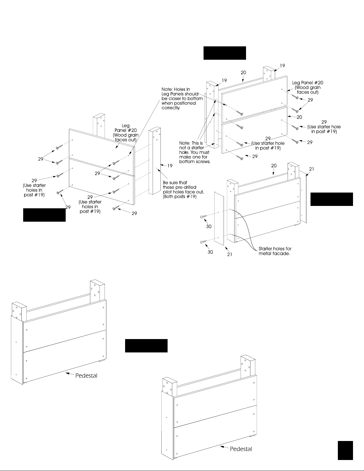
ASSEMBLE TWO LEG PEDESTALS AS FOLLOWS:
1. Begin by opening hardware kits and sort hardware.
Attach leg panels #20 to leg posts #19 using screws
#29. (Note: Set of screw holes should be closer to the
bottom of the panel when positioned correctly.) Start by
installing the top screws in bottom leg panel using the
pre-drilled starter holes in post #19. Square edge of leg
panel up to edge of post #19 then, install the bottom two
screws #29. Butt top leg panel #20 up to bottom leg
panel and secure in place using screws #29. (See Figure
1a) Do not tighten screws #29 until instructed to do so.
Be sure the wood grain faces out away from
posts #19.
Figure 1b
Figure 1a
Figure 1c
2. Attach inside leg panels #20 to leg posts #19 in same manner
as outside leg panels (See Figure 1b) Do not tighten screws #29
until instructed to do so. Be sure the wood grain faces out
away from posts #19.
3. Attach metal leg facades #21 to pedestals. Attach leg facade
using two screws #30 and two plastic spacers #13. Locate leg
facade #21 by lining up the holes in the facade with the starter
holes in the leg post. See figure 1c.
4. Set up pedestals so that they face each other.
Figure 2
Page
3
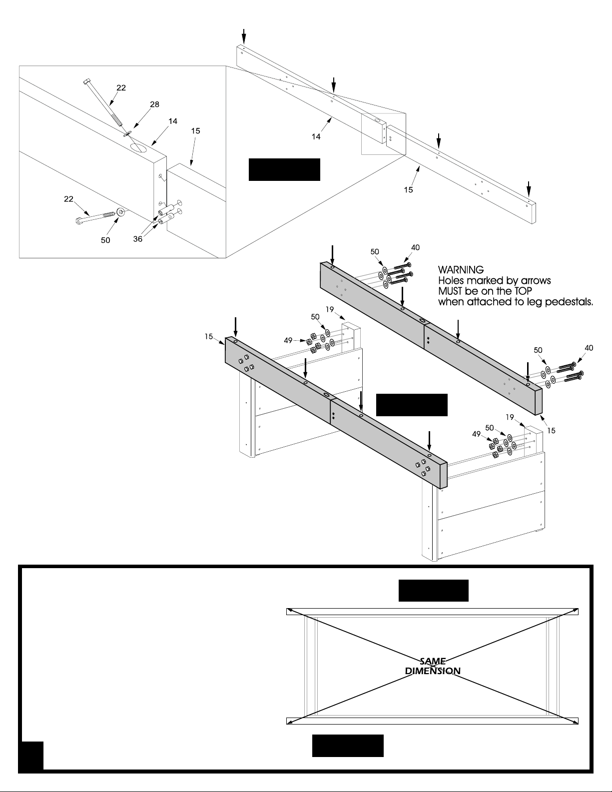
Figure 3
5. Attach a beam mate #15 to main beam #14 using
two bolts #22, two washers #28 and two dowel
connectors #36. See figure 3. Tighten bolts tight.
Repeat for other main beam #14.
Important! Holes marked by
arrows must be on top on
both beam sections.
6. Attach a beam assembly by using
four bolts #40, eight washers
#50, and four locknuts #49 for
each of the leg post #19. Place one
washer between the bolts and beam
and one between leg posts and locknuts.
Tighten these bolts securely. (See figure
4)
7. Attach other beam #15 to the other side the
same way. (See figure 4)
Make sure the holes in the edge of the beams #15 are on
the top of the beams when attached.
8. Place the frame in its final location. Square
the base frame assembly by measuring
diagonally from the corner of one beam to
the opposite corner of the other beam. (See
Figure 5) Nudge the frame until both diagonals are equal (within 1/16 inch). Go back
and tighten all loose screws, nuts and bolts.
Figure 4
Top View
Page
4
Figure 5
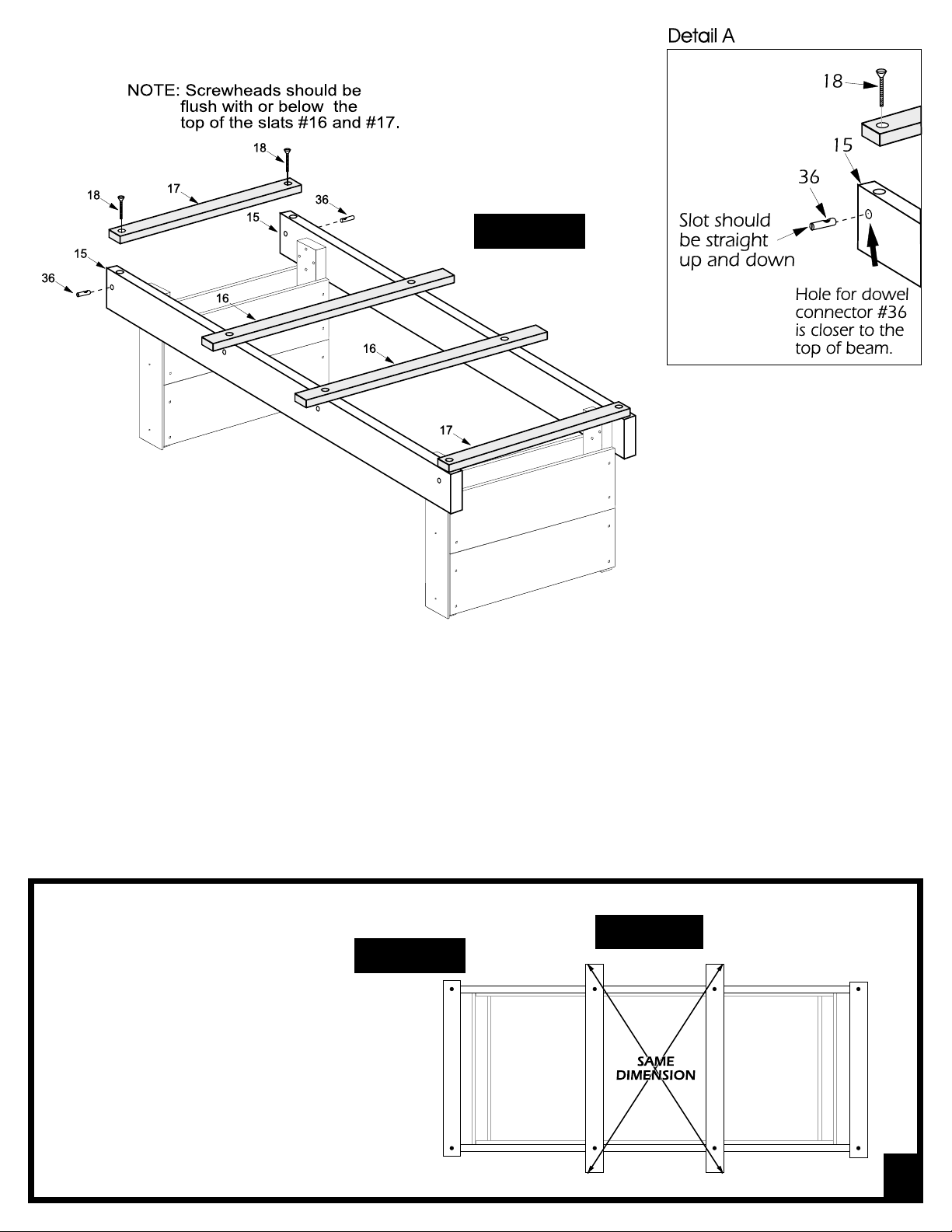
Figure 6
9. Place long slats #16 (50 inches long) and short slats #17 (36 inches long) across table from beam to beam as shown
in figure 6. Make sure to use the two shorter slats #17 on the ends of the beams and the two longer slats #16 in the center
as shown. Insert four dowel connectors #36 into the four holes in the side of each of the beams #15 these holes should be
closer to the top of the beams #4. (See Detail A). Attach the slats #16, and #17 to the wooden beams #15 by placing
screws #18 through the slats and into the dowel connectors #36 that are in the beams #15 and tighten, make sure not to
over tighten them. (See figure 4 and detail A))
HINT: When holes are lined up, the slot in the dowel connector should be vertical. After holes line up, insert screws #18 into
slats and down into dowel connectors. It is recommended to start the screws by hand and not forcing them with power tools
until you are sure threads are engaged properly. Do not tighten completely yet.
Top View
Figure 7
10. Square up the long slats #16 by measuring
diagonally, similar to the method used earlier to square up base frame. (See Figure 7)
After squaring up slats, tighten all the screws
holding slats #16 and #17 to the beams.
Page
5
 Loading...