


GB
Aristo
WO100
4
Instruction manual
Valid from program version 1.60444 405 074 GB 110428

1 INTRODUCTION 4. . . . . . . . . . . . . . . . . . . . . . . . . . . . . . . . . . . . . . . . . . . . . . . . . . .
1.1 Selection of language 4. . . . . . . . . . . . . . . . . . . . . . . . . . . . . . . . . . . . . . . . . . . . . . . . . . . . . .
1.2 Control panel 5. . . . . . . . . . . . . . . . . . . . . . . . . . . . . . . . . . . . . . . . . . . . . . . . . . . . . . . . . . . . .
2 SETTING RANGE 6. . . . . . . . . . . . . . . . . . . . . . . . . . . . . . . . . . . . . . . . . . . . . . . . . .
3 WELDING PARAMETERS 7. . . . . . . . . . . . . . . . . . . . . . . . . . . . . . . . . . . . . . . . . . .
3.1 Sectors 7. . . . . . . . . . . . . . . . . . . . . . . . . . . . . . . . . . . . . . . . . . . . . . . . . . . . . . . . . . . . . . . . . .
3.2 Welding current 8. . . . . . . . . . . . . . . . . . . . . . . . . . . . . . . . . . . . . . . . . . . . . . . . . . . . . . . . . . .
3.2.1 Pulsed current/continuous current 8. . . . . . . . . . . . . . . . . . . . . . . . . . . . . . . . . . . . . . .
3.2.2 Special pulsing 9. . . . . . . . . . . . . . . . . . . . . . . . . . . . . . . . . . . . . . . . . . . . . . . . . . . . . . .
3.3 Wire feed 10. . . . . . . . . . . . . . . . . . . . . . . . . . . . . . . . . . . . . . . . . . . . . . . . . . . . . . . . . . . . . . . . .
3.4 Rotation 10. . . . . . . . . . . . . . . . . . . . . . . . . . . . . . . . . . . . . . . . . . . . . . . . . . . . . . . . . . . . . . . . . .
3.5 Arc voltage control (AVC) 10. . . . . . . . . . . . . . . . . . . . . . . . . . . . . . . . . . . . . . . . . . . . . . . . . . .
3.6 Weaving 11. . . . . . . . . . . . . . . . . . . . . . . . . . . . . . . . . . . . . . . . . . . . . . . . . . . . . . . . . . . . . . . . .
3.7 Gas 12. . . . . . . . . . . . . . . . . . . . . . . . . . . . . . . . . . . . . . . . . . . . . . . . . . . . . . . . . . . . . . . . . . . . .
3.8 Preheating 12. . . . . . . . . . . . . . . . . . . . . . . . . . . . . . . . . . . . . . . . . . . . . . . . . . . . . . . . . . . . . . . .
3.9 Slope 12. . . . . . . . . . . . . . . . . . . . . . . . . . . . . . . . . . . . . . . . . . . . . . . . . . . . . . . . . . . . . . . . . . . .
4 MENU STRUCTURE 13. . . . . . . . . . . . . . . . . . . . . . . . . . . . . . . . . . . . . . . . . . . . . . . .
5 MENUS 14. . . . . . . . . . . . . . . . . . . . . . . . . . . . . . . . . . . . . . . . . . . . . . . . . . . . . . . . . . .
5.1 Weld area 14. . . . . . . . . . . . . . . . . . . . . . . . . . . . . . . . . . . . . . . . . . . . . . . . . . . . . . . . . . . . . . . .
5.1.1 Parameters 14. . . . . . . . . . . . . . . . . . . . . . . . . . . . . . . . . . . . . . . . . . . . . . . . . . . . . . . . . .
5.1.2 File manager 20. . . . . . . . . . . . . . . . . . . . . . . . . . . . . . . . . . . . . . . . . . . . . . . . . . . . . . . . .
5.1.3 Information 21. . . . . . . . . . . . . . . . . . . . . . . . . . . . . . . . . . . . . . . . . . . . . . . . . . . . . . . . . . .
5.1.4 Joint information 21. . . . . . . . . . . . . . . . . . . . . . . . . . . . . . . . . . . . . . . . . . . . . . . . . . . . . .
5.1.5 Settings 23. . . . . . . . . . . . . . . . . . . . . . . . . . . . . . . . . . . . . . . . . . . . . . . . . . . . . . . . . . . . .
5.1.6 Limits 24. . . . . . . . . . . . . . . . . . . . . . . . . . . . . . . . . . . . . . . . . . . . . . . . . . . . . . . . . . . . . . .
5.2 Design area 24. . . . . . . . . . . . . . . . . . . . . . . . . . . . . . . . . . . . . . . . . . . . . . . . . . . . . . . . . . . . . .
5.3 Settings 24. . . . . . . . . . . . . . . . . . . . . . . . . . . . . . . . . . . . . . . . . . . . . . . . . . . . . . . . . . . . . . . . . .
5.3.1 Appearance 25. . . . . . . . . . . . . . . . . . . . . . . . . . . . . . . . . . . . . . . . . . . . . . . . . . . . . . . . . .
5.3.2 Users settings 26. . . . . . . . . . . . . . . . . . . . . . . . . . . . . . . . . . . . . . . . . . . . . . . . . . . . . . . .
5.4 Login 28. . . . . . . . . . . . . . . . . . . . . . . . . . . . . . . . . . . . . . . . . . . . . . . . . . . . . . . . . . . . . . . . . . . .
5.5 Library 28. . . . . . . . . . . . . . . . . . . . . . . . . . . . . . . . . . . . . . . . . . . . . . . . . . . . . . . . . . . . . . . . . . .
5.5.1 Weld programs 29. . . . . . . . . . . . . . . . . . . . . . . . . . . . . . . . . . . . . . . . . . . . . . . . . . . . . . .
5.5.2 Search filter 29. . . . . . . . . . . . . . . . . . . . . . . . . . . . . . . . . . . . . . . . . . . . . . . . . . . . . . . . . .
5.6 Manual mode 30. . . . . . . . . . . . . . . . . . . . . . . . . . . . . . . . . . . . . . . . . . . . . . . . . . . . . . . . . . . . .
5.6.1 Motor selection 30. . . . . . . . . . . . . . . . . . . . . . . . . . . . . . . . . . . . . . . . . . . . . . . . . . . . . . .
5.6.2 Gas valve control 31. . . . . . . . . . . . . . . . . . . . . . . . . . . . . . . . . . . . . . . . . . . . . . . . . . . . .
5.6.3 Run motor 31. . . . . . . . . . . . . . . . . . . . . . . . . . . . . . . . . . . . . . . . . . . . . . . . . . . . . . . . . . .
5.6.4 Weaving simulation 31. . . . . . . . . . . . . . . . . . . . . . . . . . . . . . . . . . . . . . . . . . . . . . . . . . .
5.7 Tool editor 31. . . . . . . . . . . . . . . . . . . . . . . . . . . . . . . . . . . . . . . . . . . . . . . . . . . . . . . . . . . . . . . .
5.7.1 Load/save 32. . . . . . . . . . . . . . . . . . . . . . . . . . . . . . . . . . . . . . . . . . . . . . . . . . . . . . . . . . .
5.7.2 Edit settings 33. . . . . . . . . . . . . . . . . . . . . . . . . . . . . . . . . . . . . . . . . . . . . . . . . . . . . . . . . .
5.7.3 Edit motor data 34. . . . . . . . . . . . . . . . . . . . . . . . . . . . . . . . . . . . . . . . . . . . . . . . . . . . . . .
5.8 Logs 34. . . . . . . . . . . . . . . . . . . . . . . . . . . . . . . . . . . . . . . . . . . . . . . . . . . . . . . . . . . . . . . . . . . . .
5.8.1 Event log 34. . . . . . . . . . . . . . . . . . . . . . . . . . . . . . . . . . . . . . . . . . . . . . . . . . . . . . . . . . . .
5.8.2 Quality data 37. . . . . . . . . . . . . . . . . . . . . . . . . . . . . . . . . . . . . . . . . . . . . . . . . . . . . . . . . .
5.9 Manual welding 38. . . . . . . . . . . . . . . . . . . . . . . . . . . . . . . . . . . . . . . . . . . . . . . . . . . . . . . . . . .
5.10 Generate 41. . . . . . . . . . . . . . . . . . . . . . . . . . . . . . . . . . . . . . . . . . . . . . . . . . . . . . . . . . . . . . . . .
Rights reserved to alter specifications without notice.
TOCe
- 2 -

6 TECHNICAL TERMS 42. . . . . . . . . . . . . . . . . . . . . . . . . . . . . . . . . . . . . . . . . . . . . . . .
ORDERING NUMBER 43. . . . . . . . . . . . . . . . . . . . . . . . . . . . . . . . . . . . . . . . . . . . . . . . .
Rights reserved to alter specifications without notice.
TOCe
- 3 -

GB
1 INTRODUCTION
The manual describes the use of a control panel. WO100
4
For general information about operation, see the instruction manual for the power
source and control unit.
The text displayed in the panel is available in the following languages: Swedish,
Norwegian, Danish, Finnish, English, German, French, Dutch, Spanish, Italian,
Portuguese, Greek, Polish, Czech, Hungarian, Slovenian and Russian.
1.1 Selection of language
The first time you start up the machine, the following is displayed.
On delivery the system is set to English. To select your preferred language:
S Press the ”Menu” button
so that the menu is
activated and shows the
options available at this
level.
S Turn the knob until
”Settings” is highlighted,
then press the knob.
S ”Appearance” is
highlighted, press the knob.
S ”General” is highlighted,
press the knob. The
”Language” field with the
word ”English” is framed.
Turn the knob to select
your preferred language.
S Activate your preferred language by pressing the knob.
bi16d1ea
- 4 -
© ESAB AB 2007
GB
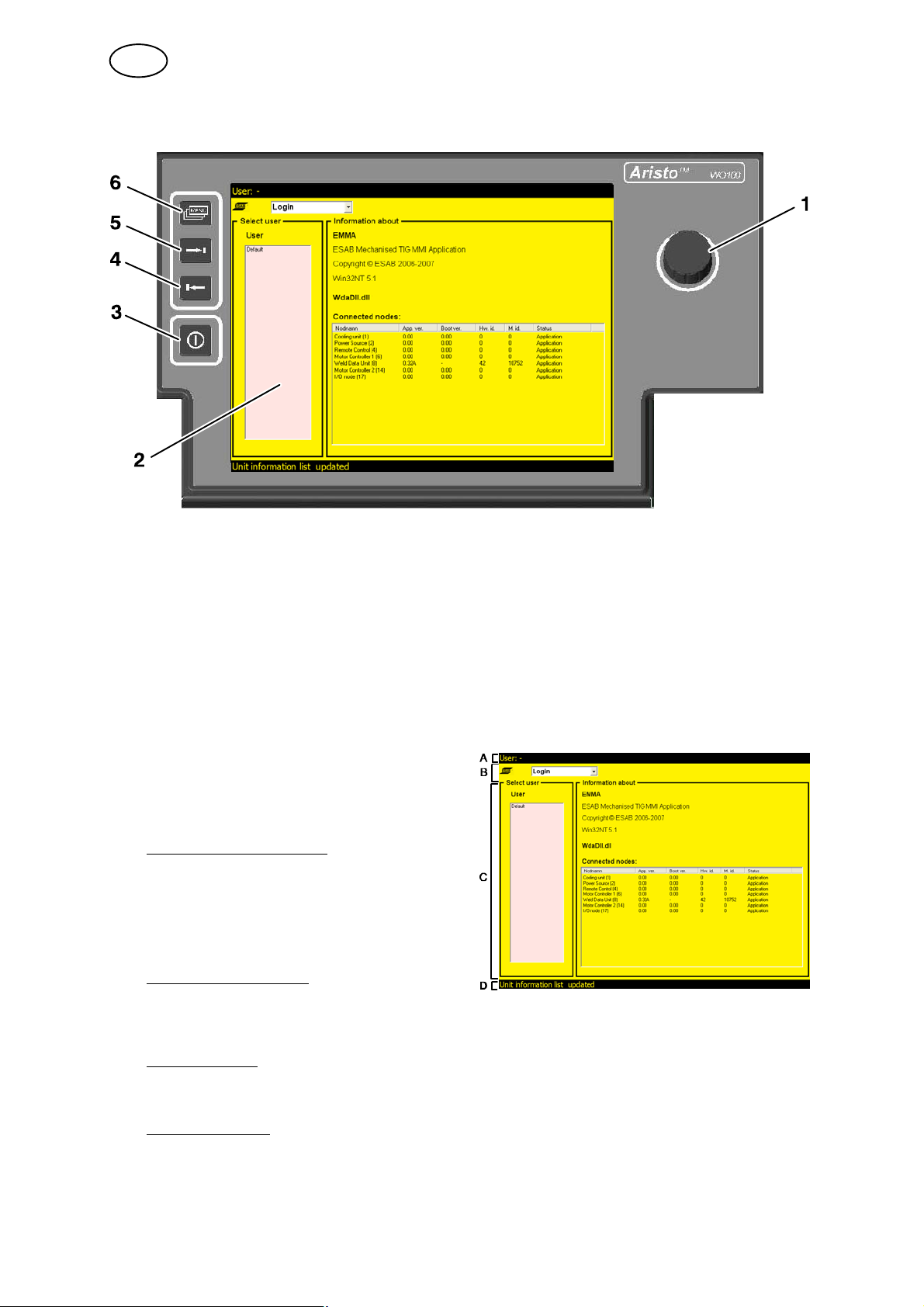
1.2 Control panel
1 Knob
For moving, activating and setting parameter values.
There are three knob functions:
S Turn to the left
S Turn to the right
S Press the knob, activate
2 Display
There are four view fields in the
display:
Upper status field (A)
Information about the weld area's
program name, user, which type of
tool is connected and the tube
dimension.
Main menu field (B)
Different menus, see chapter 5 ”Menu
Structure”.
View field (C)
For editing weld programs, saving programs, information, appearance, etc.
Status field (D)
Shows general information, error messages and current welding data (position,
voltage, current)
- 5 -
bi16d1ea
© ESAB AB 2007

GB
3 Quick stop/Restart
Immediate stop of the welding process. Gas postflow occurs according
to information from end sector.
Pressing the button again initiates restart with parameters from start
sector; the welding process continues from the point in the weld
program at which the interruption occurred.
4 Left arrow
Moving to the left in the menus and back in the main menus
5 Right arrow
Moving to the right in the menus and forward in the main menus
6 Main menu
Moving to the main menu field
2 SETTING RANGE
Parameter Setting range
Sector
Breakpoints
Degrees
Welding current
Peak current
Background current
Pulse time
Background time
Special pulsing
Wire feed
Peak wire feed speed
Background wire feed speed
Rotation
Rotation speed
Rotation direction
Pulsed rotation
1)
0 - 50
0.000 - 9.999
0 - 3599°
3 - 400 A
3 - 400 A
0.01 - 25 s
0.01 - 25 s
Off and On
15 - 250 cm/min
15 - 250 cm/min
5 - 100 % of the welding tool's maximum speed
Forwards and Backwards
0.05 - 25 s
2)
2)
AVC
Peak voltage
Background voltage
Delay time
Weaving
Weaving amplitude
Weaving speed
Pause time (right and left)
bi16d1ea
8 - 33 V
8 - 33 V
0.5 - 6000 s
0 - 12 mm (5 mm)
2 - 12 mm/s (5 mm/s)
0.1 - 10 s (1 s)
- 6 -
© ESAB AB 2007
GB
Parameter Setting range
Gas
Weld gas preflow time
Weld gas postflow time
Start gas
Root gas
Preheating
Preheating time 0 - 600 s
Slope
Slope up time
Slope down time
1)
The maximum welding current for air-cooled tube welding tools is 100 A.
The maximum welding current for water-cooled tube welding tools is 400 A.
See also the instruction manual for the tube welding tool in question.
2)
Depends on power source
0 - 6000 s
0 - 6000 s
0 - 6000 s
0 - 6000 s
0.1 - 25 s
0.1 - 25 s
3 WELDING PARAMETERS
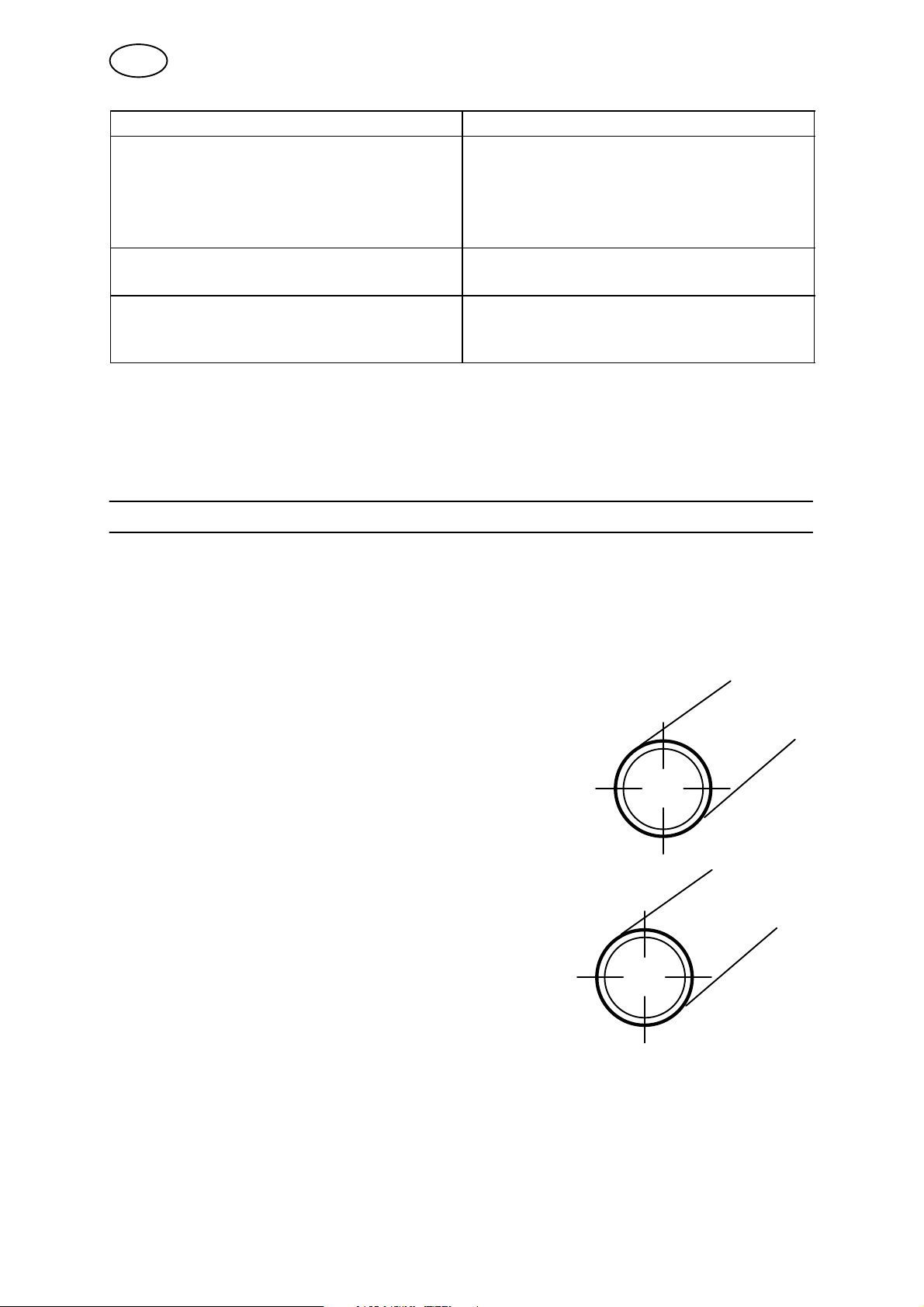
3.1 Sectors
A program for tube welding can be divided into different sections: sectors. Each
sector corresponds to one section of the tube's circumference. The maximum
number of sectors for one program is 50.
A sector can be assigned its own set of values
for different welding parameters, such as
current, rotation speed and wire feed speed, etc.
This allows the welding to be performed using
different welding parameter settings for different
sections of the tube joint.
The division into sectors is done by
indicating different breakpoints or degrees
around the circumference of the tube. Each
breakpoint or degree constitutes the starting
point for a new sector. In the figure,
breakpoint 0.000, 0 degrees, is the starting
point for sector 1, breakpoint 0.250, 90
degrees, the starting point for sector 2, and
so on.
The power source allows welding of up to
10 turns in the same weld joint. (The
welding tool can be rotated 10 times around
the tube.)
Sector 4 Sector 1
Sector 3 Sector 2
0.000
Sector 4 Sector 1
0.750 0.250
Sector 3 Sector 2
0.500
Note: A sector may not be less than 10 thousandths, or 3.6 degrees, of a turn.
bi16d1ea
- 7 -
© ESAB AB 2007
GB
S Turn 1 =
breakpoints 0.000 - 0.999
0 - 359 degrees
S Turn 3 =
breakpoints 2.000 - 2.999
720 - 1079 degrees
S Turn 5=
breakpoints 4.000 - 4.999
1440 - 1799 degrees
S Turn 7=
breakpoints 6.000 - 6.999
2160 - 2519 degrees
S Turn 9=
breakpoints 8.000 - 8.999
2880 - 3239 degrees
S Turn 2 =
breakpoints 1.000 - 1.999
360 - 719 degrees
S Turn 4 =
breakpoints 3.000 - 3.999
1080 - 1439 degrees
S Turn 6=
breakpoints 5.000 - 5.999
1800 - 2159 degrees
S Turn 8 =
breakpoints 7.000 - 7.999
2520 - 2879 degrees
S Turn 10 =
breakpoints 9.000 - 9.999
3240 - 3599 degrees
To conclude a weld program, a so-called end sector is indicated.
For a sector to be counted as an end sector the following two conditions must be
fulfilled:
S There is no subsequent sector.
S The welding current value for the sector is 0 ampere.
3.2 Welding current
Six parameters are represented in the parameter group for welding current:
S Peak current
S Background current
S Pulse time
S Background time
S Special pulsing
S Slope, see point 3.9.
Pulse time
Background time
Peak current
Background current
TIG welding with pulsed current
Welding current can be pulsed or continuous (not pulsed).
3.2.1 Pulsed current/continuous current
When welding using a pulsed current, peak current, background current, pulse
time and background time must be given a value.
When welding using a continuous current, however, you need only enter a
parameter value for peak current. Entering a value for background current will result
in a pulsed current.
bi16d1ea
- 8 -
© ESAB AB 2007

GB
The welding current (pulsed current) can be synchronized with the weaving motion
so that the peak current will start when the electrode is at the extremes of the
weaving motion. This is also called special pulsing. (Even when special pulsing is
not used, peak current still starts at the extremes of the weaving motion.)
3.2.2 Special pulsing
Special pulsing means that the welding current is synchronized with the weaving
motion, i.e. you get peak current when the electrode is at the extremes of the
weaving motion. Thus, the peak current time is determined by the pause time for
each extreme.
Special pulsing can be used in combination with both continuous and pulsed
rotation. Special pulsing with pulsed rotation, also called square-wave pulsing,
means that the gear ring rotates when the electrode is at either extreme of the
weaving motion.
A = Background current
B = Peak current
Rotation direction Rotation direction
Special pulsing with
continuous rotation
Special pulsing with
pulsed rotation
With special pulsing, the wire feed can be either continuous or pulsed. With pulsed
wire feed, synchronization with the welding current takes place in the manner
described above, see also chapter 3.3”Wire Feed Speed”.
bi16d1ea
- 9 -
© ESAB AB 2007

GB
3.3 Wire feed
Wire feed speed is used to indicate the feed speed for the filler wire in cm/minute.
Speed can be pulsed or continuous (not pulsed).
Three parameters are represented in the parameter group for wire feed:
S Peak wire feed
S Background wire feed
S Slope, see point 3.9.
For welding using a continuous (not pulsed) wire feed, only the peak wire feed
parameter needs to be entered.
For welding with a pulsed wire feed speed, both the peak wire feed and the
background wire feed parameters need to be entered.
The pulsed wire feed speed is always automatically synchronized with the welding
current so that the wire feed speed is high when using peak current and low when
using background current.
3.4 Rotation
Used to indicate the rotation speed of the electrode around the workpiece. It is
indicated in mm/min.
The rotation speed can be pulsed or continuous (not pulsed).
Four parameters are represented in the parameter group for rotation:
S Rotation speed
S Rotation direction
S Pulsed rotation
S Slope, see point 3.9.
Pulsed rotation is automatically synchronized with the welding current so that the
welding tool is stationary at peak current and rotates at background current.
3.5 Arc voltage control (AVC)
Used during welding with welding tools equipped with an AVC unit.
Arc voltage control (AVC) means that the arc voltage, and therefore the arc length
(the distance between the electrode point and workpiece), is regulated automatically
during ongoing welding.
Four parameters are represented in the parameter group for arc voltage control
(AVC):
S Peak voltage (Arc voltage at peak current)
S Background voltage (Arc voltage at background current)
S Delay time
S Slope, see point 3.9.
The parameters peak voltage and background voltage are used to enter the
reference value for arc voltage control at peak current and background current. With
continuous current, only the peak voltage parameter needs to be entered.
bi16d1ea
- 10 -
© ESAB AB 2007

GB
If no value is indicated for peak voltage, use a value measured immediately after
welding began as the reference value.
If no value is indicated for background voltage and pulsed welding current is
entered, there is no arc voltage control with background current.
Note: It is not possible to indicate a time slope in sector 1 for peak voltage and
background voltage.
It is possible to enter a delay time as a means of stablising the arc before arc
voltage control commences. During this delay time the AVC unit is completely
locked.
If you do not enter a delay time, the following happens:
S The delay time is the same (at least 5 seconds) as any slope up time for the
welding current. If the entered slope up time is less than 5 seconds, the AVC unit
will start up once the slope ends, but only by increasing the arc voltage (arc
length).
S If no slope up time has been entered for the welding current, a fixed delay time
of 5 seconds applies. The AVC unit is not completely locked but can increase the
arc voltage (arc length).
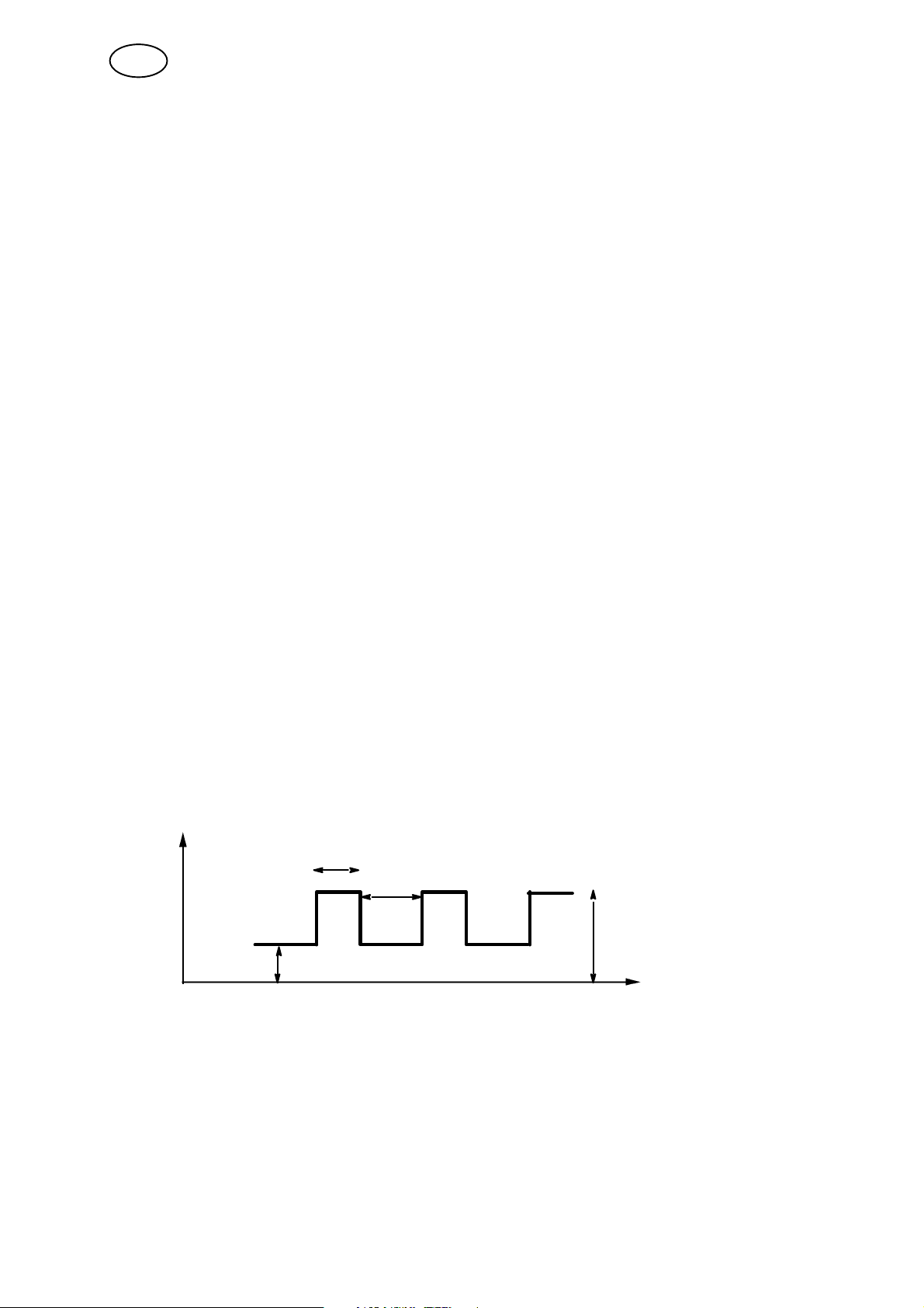
3.6 Weaving
Used if you want to weave the electrode sideways during welding when using
welding tools equipped with a weaving unit.
Five parameters are represented in the parameter group for weaving:
S Weaving amplitude
S Weaving speed
S Left pause time
S Right pause time
S Slope, see point 3.9.
Amplitude (mm)
Left pause time (s)
Right pause time (s)
Weaving speed (mm/s)
Weaving
The weaving motion can be synchronized with the welding current (pulsed current)
so that the peak current will start when the electrode reaches the extremes of the
weaving motion. This is also called `special pulsing' and is described further in
chapter 3.2.2 ”Special Pulsing”.
bi16d1ea
- 11 -
© ESAB AB 2007

GB
3.7 Gas
Three parameters are represented in the parameter group for shielding gas:
S Weld gas
S Start gas
S Root gas
Weld gas refers to the shielding gas on the upper side of the weld joint. The weld
gas parameter indicates how long the shielding gas is to flow on the upper side of
the joint before and after welding. The weld gas is monitored by a flow guard min.
4.5 l/min.
Some shielding gases, for example, helium (He), can cause problems with regard to
igniting the arc. If this type of shielding gas is to be used as weld gas, it may be
advisable to use a different gas mixture at the actual instance of starting, a so-called
start gas.
Root gas refers to the shielding gas on the underside of the weld joint. The root gas
parameter indicates how long the shielding gas is to flow on the underside of the
joint before and after welding.
If one value is entered for weld gas and another for start gas in sector 1, only the
start gas will flow. The weld gas starts flowing once the arc is ignited.
3.8 Preheating
Preheating is used to heat the workpiece at the starting point in order to ensure
correct penetration of the molten pool and is defined as the time elapsing between
arc ignition and the start of the rotary motion. If no value has been entered for
preheating, rotation will start as soon as the arc ignites.
3.9 Slope
A slope may be indicated for certain parameters. A slope is the time during which the
value of the parameter gradually changes from the value in the preceding sector to
the value entered for the current sector.
Slope up = gradual increase, if the preceding value is lower than the entered value.
Slope down = gradual decrease, if the preceding value is higher than the entered
value.
The maximum period a slope can run depends on the duration of a particular sector.
If the slope time is of the same duration as the sector, this is called a `sector slope'.
bi16d1ea
- 12 -
© ESAB AB 2007

GB
4 MENU STRUCTURE
Weld area
Parameters File manager Information Joint info. Settings Limits
Table
· Edit table
· Show/hide
· Weld
control
· Edit
Parameters File manager Information Joint info. Settings Limits
Graphical
· Current
· Wire feed
· Rotation
· Weaving
· AVC
· Gas
· General
· Description
· Tube
· Electrode
· Wire
· Gas
Design area
· Visualization
· Parameter
values
· Tool
settings
· Tube
settings
Table
· Edit table
· Show/hide
· Edit
Graphical
· Current
· Wire feed
· Rotation
· Weaving
· AVC
· Gas
· General
· Description
· Tube
· Electrode
· Wire
· Gas
· Visualization
· Parameter
values
· Tool
settings
· Tube
settings
bi16d1ea
- 13 -
© ESAB AB 2007

GB
Settings Login Library Manual
mode
Appearance User · Weld
program
· Search filter · Run motor
· General
· Quality
data
Tool
editor
Load/
save
· Tool
selection
· Tool
action
Change
settings
· General
· Parameter
limits
Change
motor data
· Change
parameter
· Show para
meters
· Motor selection
· Gas valve control
· Weaving simulation
Logs Manual
Event
log
Generate
welding
Quality data
· Quality data
files
· Contents
5 MENUS
There are two work areas where you can view and edit welding parameters, Weld
area (see chapter 5.1) and Design area (see chapter 5.2).
5.1 Weld area
In this view, you can view and edit parameters in a weld program and control the
welding process. The weld program in the weld area controls the welding process.
You can enter the weld area's parameters by loading a weld program from the
library, generating a basic weld program or editing the parameters manually.
5.1.1 Parameters
This menu option is solely an archive for other menu options.
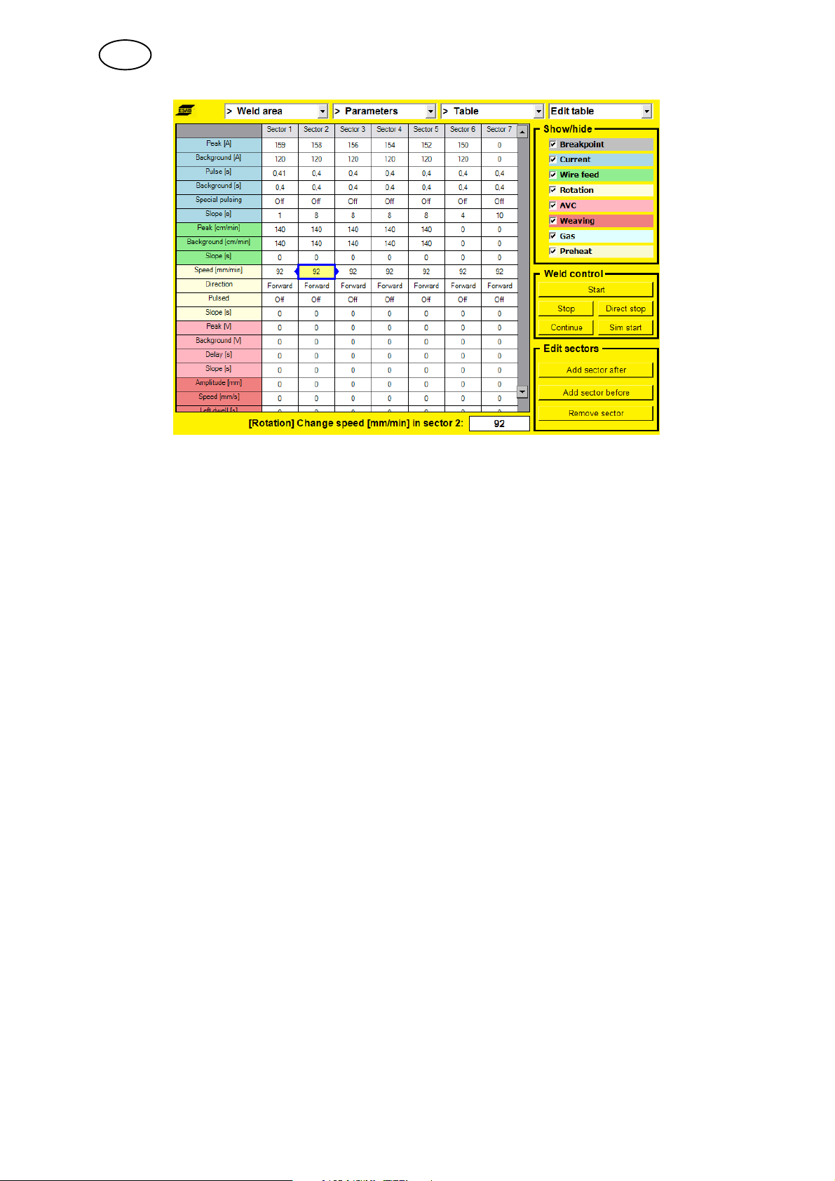
Weld area --> Parameters --> Table
Here you can view and edit welding parameters in table form and start and stop the
welding process.
bi16d1ea
- 14 -
© ESAB AB 2007
GB
Each parameter in a parameter group is highlighted in the group's colour.
A selected welding parameter in the table is indicated by a blue box with two arrows.
S To move through the table, turn the knob.
S To change direction, press the knob.
S To change a parameter value, click on the right arrow and change the parameter
values using the knob.
Menu shortcuts:
S Edit table
Highlights the table with welding parameters
S Show/hide
Shows or hides groups of welding parameters in the table.
Here you can choose which parameters are to be shown in the table by selecting
groups of parameters.
S Weld control
Highlights the start button in the weld control box.
The buttons in this box control the welding process. You can start, stop, direct
stop, continue or simulate the start of the welding process.
S Edit sectors
Highlights the button 'Add sector after' in the Edit sectors box.
The number of sectors can be increased or decreased using this box. It is
possible to add new sectors before or after an existing sector and remove
sectors in the weld program.
- 15 -
bi16d1ea
© ESAB AB 2007

GB
Weld area --> Parameters --> Graphical--> Current
In this view, you can view and edit welding parameters for current in a graphical
representation.
The current's peak and background values are represented in a coordinate system.
The Y-axis represents the current's value in ampere, while the X-axis represents
time.
The current's various values per sector are connected and form a line.
Green indicates the peak current value per sector, while blue indicates the
background current value per sector.
Slope is represented as an angled line from the start of the sector, which ends where
the slope time stops on the X-axis.
S Zoom
Here you can adjust the scale of the X-axis in the coordinate system.
S Weld control
The buttons in this box control the welding process. You can start, stop, direct
stop, continue or simulate the start of the welding process.
S Sector information
The figures in this field show the other parameters concerned with the parameter
group for current. The sector's breakpoint is represented by a dash in a circle
(cross-section of a tube).
If the weld program extends over more than one turn, these turns are shown as
a sequence of slightly smaller circles.
The preheating time is shown in tenths of a second under the breakpoint
information.
Special pulsing on or off is shown as an image, where a red cross indicates that
special pulsing is not being used.
The relationship between pulse times is shown as a pulse cycle. Separate times
for peak and background pulse.
bi16d1ea
- 16 -
© ESAB AB 2007

GB
S Figure for breakpoints
It is possible to move, add or remove breakpoints using the knob in the figure for
breakpoints. By skipping forward to the figure and highlighting it, you can turn the
knob and move a white dash or `cursor'.
Moving a breakpoint:
S Press the knob once the cursor is on or directly next to the breakpoint cursor
(black) to be moved.
The breakpoint is `collected' by the cursor and follows this when it is turned
around in the circle.
S To confirm the new breakpoint, press the knob.
Creating a new breakpoint
S Move the cursor by turning the knob and press the knob once at the point
where you want the new breakpoint to be created.
Removing a breakpoint:
S Press the knob once the cursor is on or directly next to the breakpoint cursor
to be removed.
The breakpoint is `collected' by the cursor and follows this when it is turned
around in the circle.
S Turn the knob to the previous or next breakpoint and press the knob once.
Weld area --> Parameters --> Graphical--> Wire feed
Here you can view and edit parameters that control wire feed per sector.
The coordinate system shows the speed at which the wire will be fed out at the peak
and background value per sector.
Slope is represented as an angled line from the start of the sector for the duration
entered for the slope.
bi16d1ea
- 17 -
© ESAB AB 2007

GB
Weld area --> Parameters --> Graphical--> Rotation
Rotation speed is viewed and edited in a coordinate system with one line for each
value and time slope. The coordinate system shows breakpoints as dashed lines.
If pulsed rotation is off, this is shown by a pulse that is crossed out.
Weld area --> Parameters --> Graphical--> Weaving
This view shows the parameters that affect weaving. The amplitude is viewed and
edited in the coordinate system. Speed and pause times are viewed and edited in
the sector information field.
bi16d1ea
- 18 -
© ESAB AB 2007

GB
Weld area --> Parameters --> Graphical--> AVC
Here you can view and edit parameters that control AVC. Peak and background
voltage are shown in the coordinate system.
Delay time is viewed and edited in the sector information field.
Weld area --> Parameters --> Graphical--> Gas
Times for weld, start and root gas are viewed and edited in this view.
bi16d1ea
- 19 -
© ESAB AB 2007

GB
5.1.2 File manager
This view is used to save, copy, clear and verify weld programs.
S Save weld program
To save a weld program, select where you want the program to be saved, either
on the control unit (User defined programs) or on a USB memory device
(External memory).
Specify a file name and click the 'Save weld program' button using the knob.
S Copy weld program to another area
Depending on which work area is active, it is possible to copy the contents of
one area to another area by clicking the 'Copy this wld program to design area'
button or 'Copy this weld program to weld area' button.
S Clear, reset weld program
If you want to begin a brand new weld program, click the 'Clear weld area'
button or 'Clear design area' button.
S Verify
This function is used to check whether the weld program in the current work area
fulfils the system's requirements as follows:
S A tool is selected for the weld program.
S The connected tool is the same as the one the program is designed for (only
applies to weld area).
S The program has at least two sectors (start and stop sector).
S The final sector in the program is a stop sector (the welding current is zero).
S Selected tube diameter is supported by the selected tool.
S The welding parameters in each sector are within the limits (min. and max.
values) for the selected tool.
bi16d1ea
- 20 -
© ESAB AB 2007

GB
5.1.3 Information
Used to enter information about the weld program. This information does not affect
the welding process, but is an aid for describing the program in words.
S General
Program name is shown at the top of the list. This is not the same as file name in
file manager. If a program name is assigned, this is the suggestion offered for
the file name.
S Description
S Tube
S Electrode
S Wire
S Gas
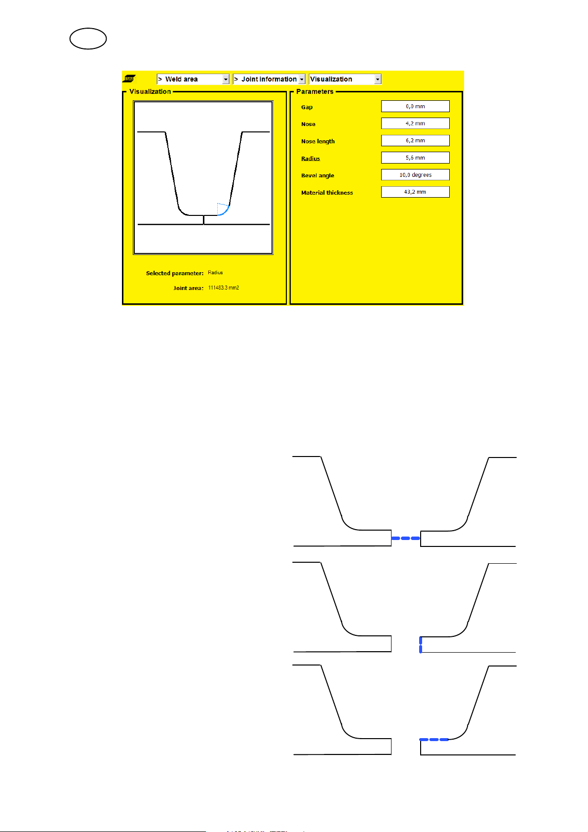
5.1.4 Joint information
In this view, you can view and change how the joint will look to suit the weld
program. This is only information about the weld program. It does not affect the
welding process.
In the ”Visualization, Visualization” field, it is possible to view a graphical
representation of the joint. In the ”Parameters” field, you can view those values
relevant to the joint. Values that affect the joint can be changed in both fields.
bi16d1ea
- 21 -
© ESAB AB 2007
GB
Visualization
S Turn the knob and a blue line will indicate which parameter has been selected.
S Press the knob and the line will turn red. The value can be changed by turning
the knob.
Parameter
S Use the arrows to move between the various parameters.
S Turn the knob to change the value.
Gap
Nose
Nose length
bi16d1ea
- 22 -
© ESAB AB 2007
GB
Radius
Bevel angle
Material thickness
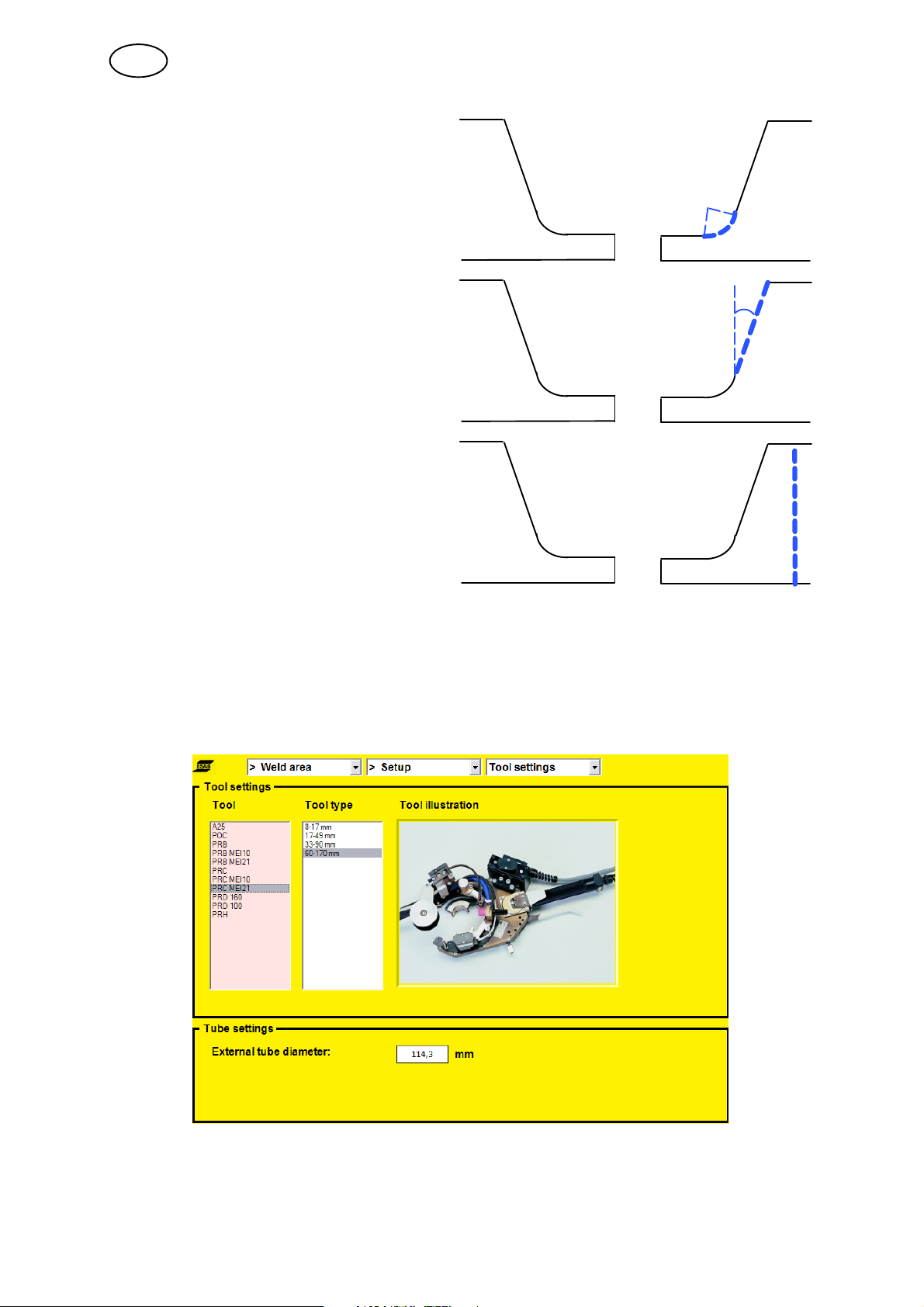
5.1.5 Settings
This view allows you to select tools and the external tube dimension for which the
weld program has been created. In the ”Tool settings” field, you can scroll through
the tools and look at an overview of the tools under ”Tool illustration”. To select a
tool, press the knob and then select the type of tool by turning and pressing the
knob.
The external tube dimension is selected by turning the knob. To confirm, press the
knob. The selected tool (”Tool ”) and dimension (”Ø:”) are visible in the top status
field, when using views from a work area.
bi16d1ea
- 23 -
© ESAB AB 2007

GB
5.1.6 Limits
This view can be used to limit how much a user can change preset parameter values
in a weld program.
In order for the restrictions to be activated, the check box ”Limits activated” must be
checked.
5.2 Design area
Weld programs can be created in the design area for use in the weld area or saved
in the library for subsequent use. To see how the design area works, refer to chapter
5.1Weld Area. The design area works in a similar way to the weld area.
The greatest difference between the two areas is that you cannot control the welding
process from the design area.
5.3 Settings
You can change the appearance of the panel and manage users in the system via
the Settings menu.
bi16d1ea
- 24 -
© ESAB AB 2007

GB
5.3.1 Appearance
Settings --> Appearance --> General
S Language
Choose from Swedish, Norwegian, Danish, Finnish, English, German, French,
Dutch, Spanish, Italian, Portuguese, Greek, Polish, Czech, Hungarian, Slovenian
and Russian.
S Angle system
Choose between thousandth points or degrees.
S Start view
Choose between starting the panel with the login menu or last viewed menu.
bi16d1ea
- 25 -
© ESAB AB 2007
GB
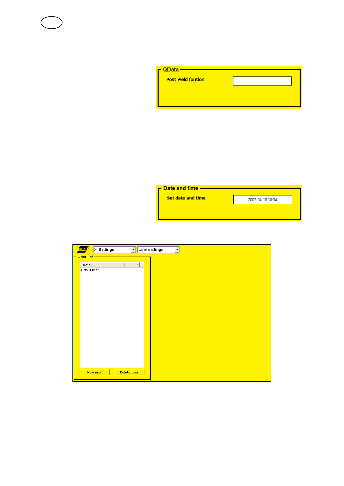
Settings --> Appearance --> QData
S Post weld function
Choose from:
S None
S Print
S Save
S Print + save
The values that are saved and printed out are set values and the measurement
values from the concluded welding process. Printing uses the integral printer in
the control unit.
The values are saved in the control panel under the ”quality data” menu, see
chapter 5.8.
Settings --> Appearance --> Date and time
Here you can view and enter the
date and time used in the system.
5.3.2 Users settings
In this view, you can add, change and delete users.
bi16d1ea
- 26 -
© ESAB AB 2007
GB
”Default user” appears the first time this menu is accessed.
To add a new user:
S Press the right or left arrow until ”New user” is
highlighted.
S Press the knob.
S Turn the knob until a suitable ID appears.
S Press the knob. The next box will be
highlighted.
S Turn the knob until a suitable letter appears,
press the knob, and so on.
S Once the name is ready, press the right
arrow until ”ok” is highlighted.
S Press the knob.
A new user appears in the list.
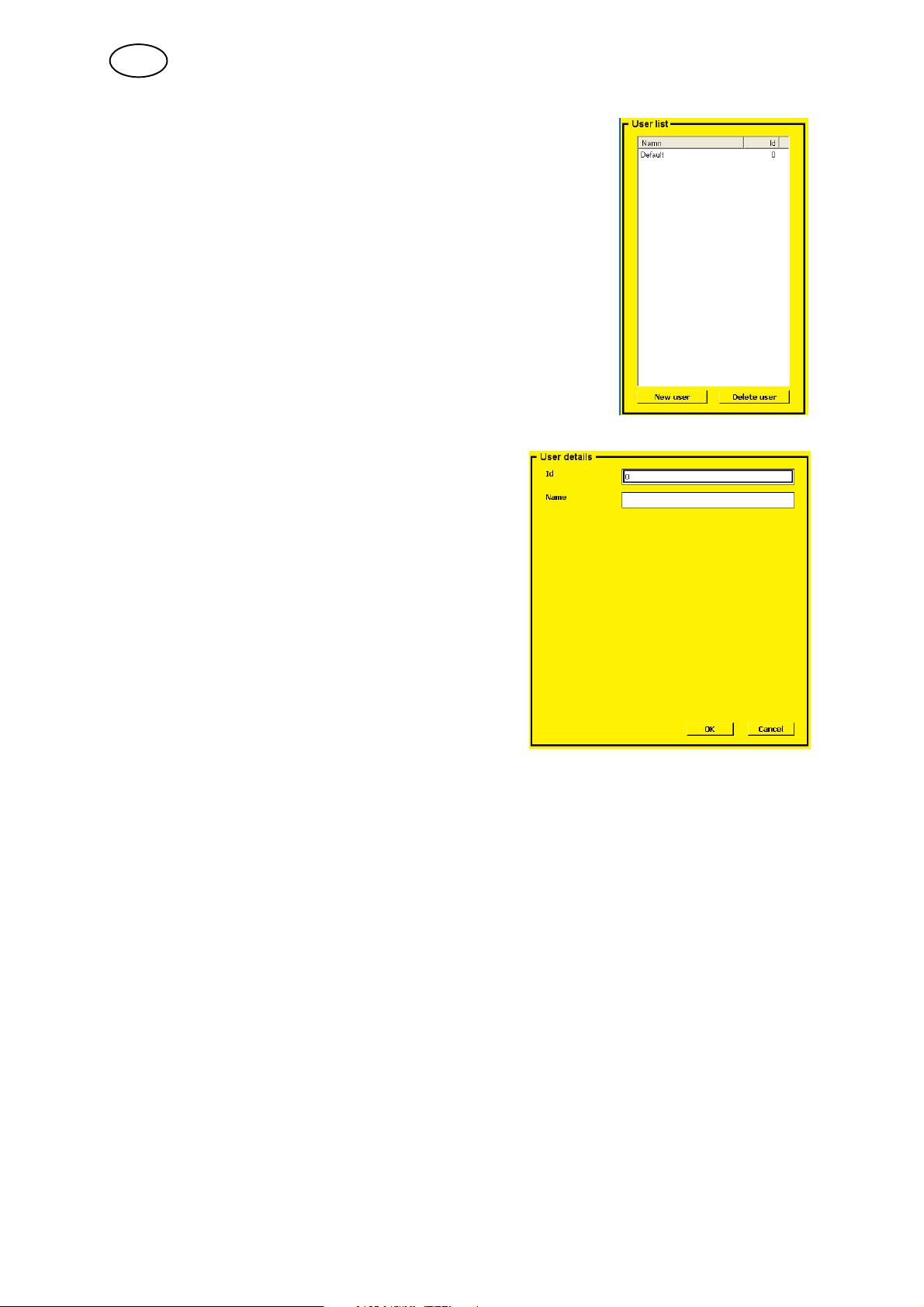
To change a user:
S Highlight the user list (by pressing the arrow keys).
S Turn the knob to select the user you want to change and press the knob.
A new field appears at the side of the user list, which allows you to change the
selected user's name or ID. Confirm the changes using ”OK”.
To delete a user:
S Highlight the user.
S Press the knob, move to the ”Delete user” button and click on the button.
The user disappears from the list.
bi16d1ea
- 27 -
© ESAB AB 2007

GB
5.4 Login
The login menu is used to select users and view which program version applies for
the panel and which units are connected. It is also possible to view version
information on the connected units/nodes.
The user name is shown in the top status field, see chapter Control Panel 1.2.
5.5 Library
Programs can be erased and retrieved for the weld area or the design area using the
library menu.
Please note that each program stored in the library is 4 - 6 Kb. The control unit's
internal memory is 1 Gb, so there is only a very small risk of the library becoming full.
NOTE! Predefined programs that begin with ESAB cannot be erased. These
programs are tested and are intended to serve as start data for similar dimensions.
bi16d1ea
- 28 -
© ESAB AB 2007
GB
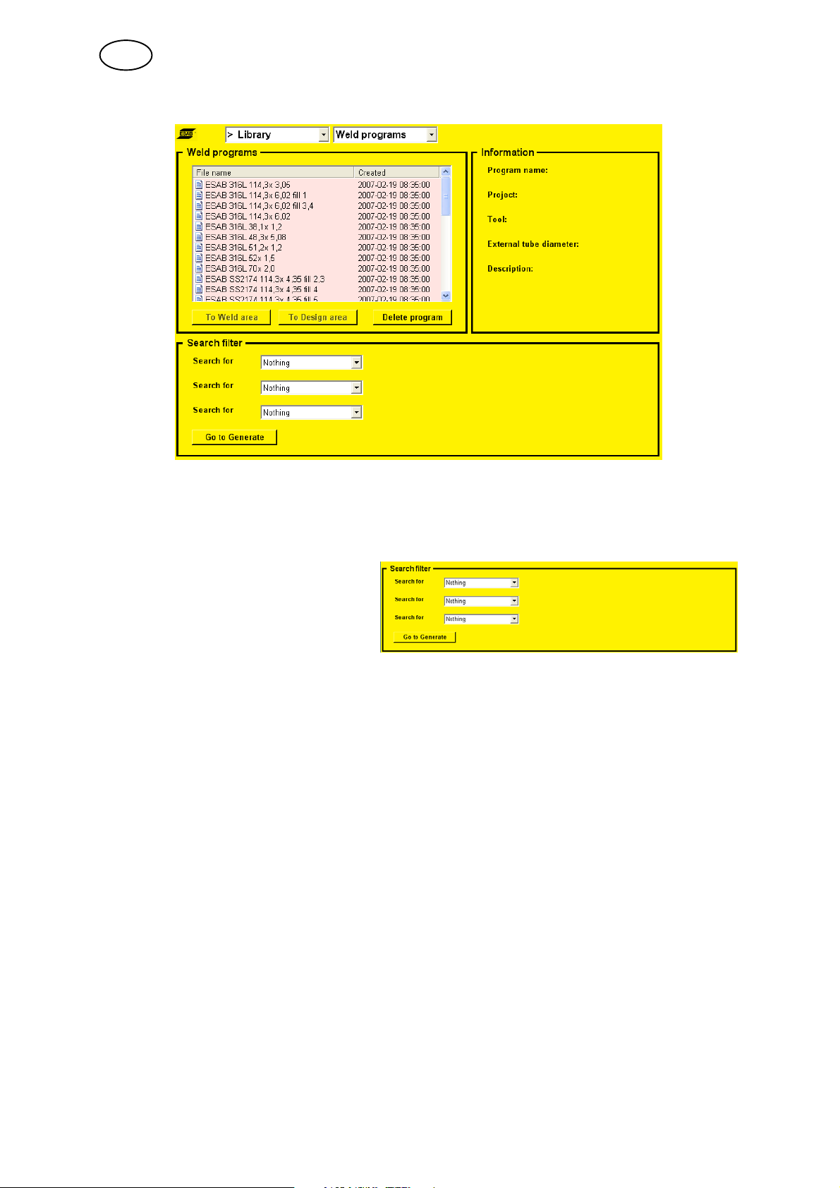
5.5.1 Weld programs
5.5.2 Search filter
Using the search filter menu it is possible to search by the following criteria in the
programs stored in the library:
S Nothing
S Name
S Project
S Material
S External tube diameter
S Tube wall thickness
If there are programs that match the criteria, these programs are displayed in the
”Weld programs” menu.
If there are no programs that match the selected criteria, continue on to ”Go to
Generate”, see chapter Generate 5.10.
bi16d1ea
- 29 -
© ESAB AB 2007
GB
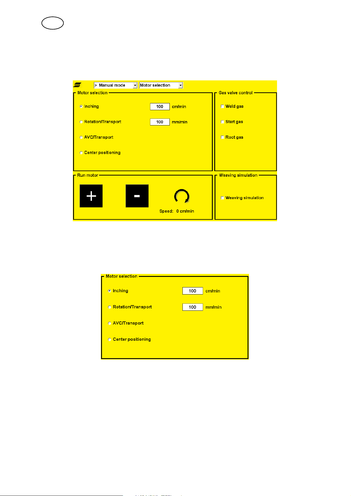
5.6 Manual mode
All motors can be checked using this menu.
5.6.1 Motor selection
Here you can choose which motor to run and also enter the motor speed.
Note: This view only shows those motors available in the system. The tool selected
in ”Weld area --> Settings” affects the information shown.
S Wire inching
Used when loading a new wire bobbin, for example.
S Rotation/Transport
Used to move the welding tool around the workpiece.
S AVC/Transport
Used to move the electrode holder up and down.
S Center positioning
Used to offset the centre point.
- 30 -
bi16d1ea
© ESAB AB 2007
GB
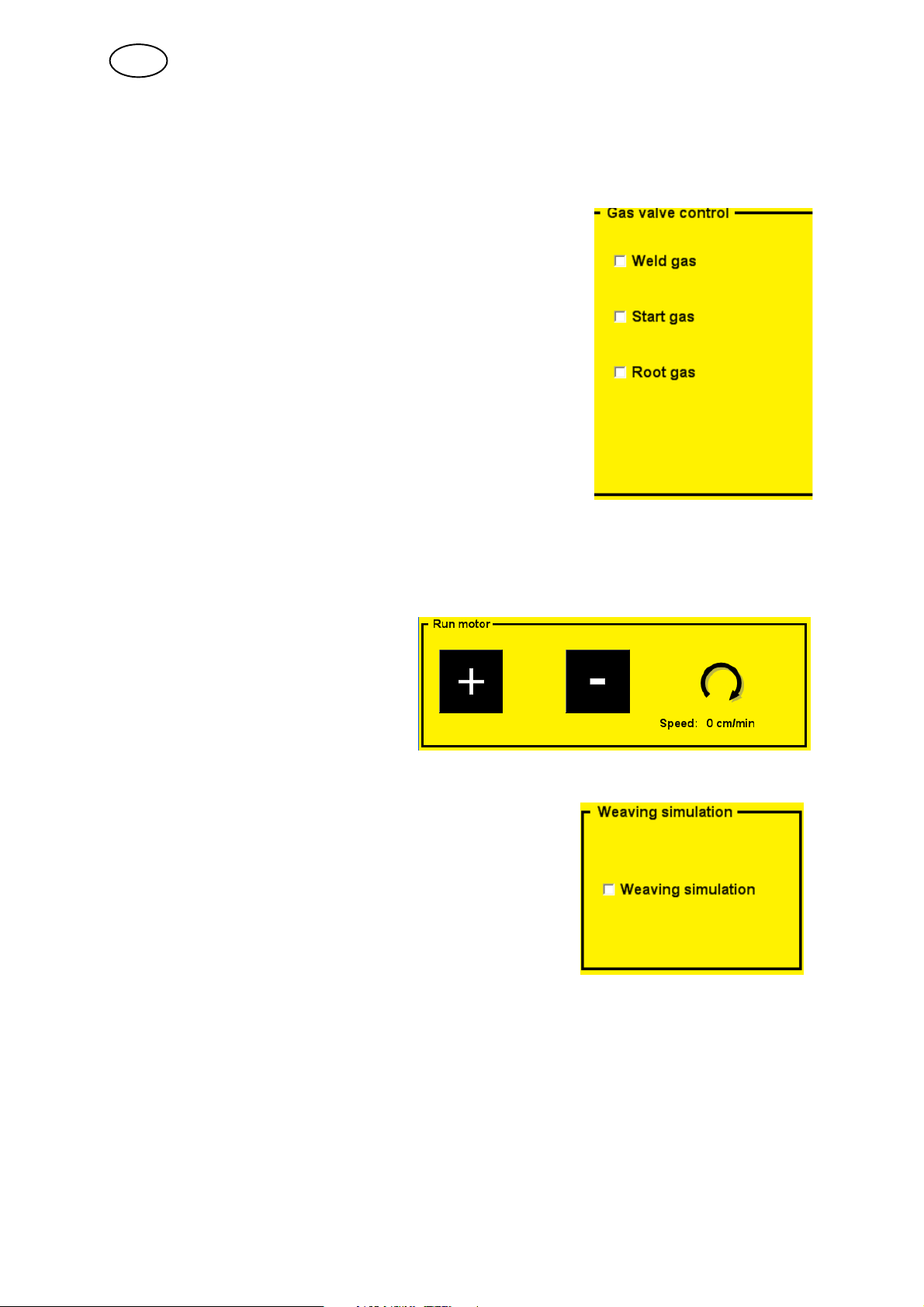
5.6.2 Gas valve control
Used when measuring the gas flow or to flush any air or moisture from the gas
hoses before welding begins.
Starts and stops the flow of gas.
If you exit this view, the gas valves close automatically.
5.6.3 Run motor
Used to view the current value of the motors.
Note! Hold in the knob to activate motor drive.
Run selected motor forwards ”+” or
backwards ”-”, and view current
speed for selected motor.
5.6.4 Weaving simulation
Used to run simulated weaving.
5.7 Tool editor
This menu is used for viewing and editing tool parameters. You can create new tools
from scratch or use predefined tools. Tools that are created by a user can be
removed, changed and saved. Predefined tools supplied with the system cannot be
changed or removed.
Please note that the tool currently being used is designated a specific work area, a
tool area. All changes performed in the views described below only affect the tool
area and are not saved until this is requested by the user.
bi16d1ea
- 31 -
© ESAB AB 2007

GB
5.7.1 Load/save
In this view, you can load a tool to work from when creating a new tool, clear
user-defined tools and save tools.
Select a tool to use (enter parameters in the tool area) by moving to the list of tools
using the left or right arrow. Turn the knob to select (highlight) a tool.
Move to the button ”Load tool”, press the knob and confirm that this is the tool you
want to use.
It is also possible to use a tool specification (tool type), for example, a tool with a
particular diameter range.
Delete a created tool by selecting it in the list, press the knob on ”Delete tool, Delete
tool” and confirm that you want to delete it using ”Yes”. It is not possible to delete
any tools supplied with the system.
You can save the created tool as a new tool or in place of an existing tool (you
cannot replace tools supplied with the system).
To save the tool as a new tool (or new tool type):
S Move to the list of tools (or tool types) using the arrow keys.
S Turn the knob to highlight ”New.... ” in the list.
S Click the menu button and select ”Tool action”.
S Move to the ”Save tooll” button.
S Press the knob and confirm that you want to save the tool as a new tool using
the ”Yes” button.
To replace an existing tool, use the same procedure as above but instead select an
existing tool from the list of tools.
You can upload tools to the system from a USB memory device, if you have a
”MechTIG_Tools.xml” tool file at the root of the file structure.
bi16d1ea
- 32 -
© ESAB AB 2007

GB
Proceed as follows:
S Connect a USB memory device to the panel's USB terminal, where the
”MechTIG_Tools.xml” file is at the very root of the file structure.
S Move to the ”Load tools from usb-memory” button using the arrow keys.
S Press the knob and confirm using ”Yes” to invalidate all the changes made to the
tool.
Clear or reset all parameters in the tool area by moving to the ”Clear tooll” button
and pressing the knob. Confirm using ”Yes” to invalidate any changes made in the
tool area.
To save all your tools to a USB memory device:
S Connect a USB memory device to the panel's USB terminal.
S Move to the ”Save tools to usb-memory” button and press the knob.
S Confirm using ”Yes” to save the tools and overwrite any tools stored on the USB
memory device.
5.7.2 Edit settings
This view is used once you have loaded a tool or when you want to create a brand
new tool. Here you can view and edit all parameter values for a tool.
The ”General settings” field contains general settings for the tool, while the
”Parameter limits” field defines the highest and lowest values for a parameter.
For min. values the value 0 means that the minimum value has not been set, while
for max. values 65535 means that the maximum value has not been set. (In some
instances, where decimals are used, 655,30 or 6553,5 may indicate not set).
bi16d1ea
- 33 -
© ESAB AB 2007

GB
5.7.3 Edit motor data
In this view, you can view and edit specific motor settings. There are motor settings
for each motor (rotation, wire feed, weaving and AVC). There are currently three
parameters per motor. The parameters are ”Setting parameter”, ”Scalefactor
position” (”numerator” and ”denominator”) and ”Scalefactor speed” (”numerator” and
”denominator”).
Add the value 100 for the parameter ”Scalefactor position (numerator)” for the motor
that controls rotation.
Proceed as follows:
S Move to the text field under ”Motor parameter” using the arrow keys.
S Turn the knob until ”Scalefactor position (numerator)” is visible in the text field
and press the knob.
S Change the value to 100 by turning the knob. Press the knob to continue.
S Turn the knob so that ”Rotation” appears in the text field. Confirm by pressing
the knob.
S Press the knob to add (or edit) the value in the list of parameters for the rotation
motor.
You can remove motor parameters by highlighting a parameter in the list of motor
parameters, pressing the knob, moving to the ”Delete” button and pressing the knob
to delete the selected parameter from the list.
5.8 Logs
This menu allows you to view logs compiled by the system.
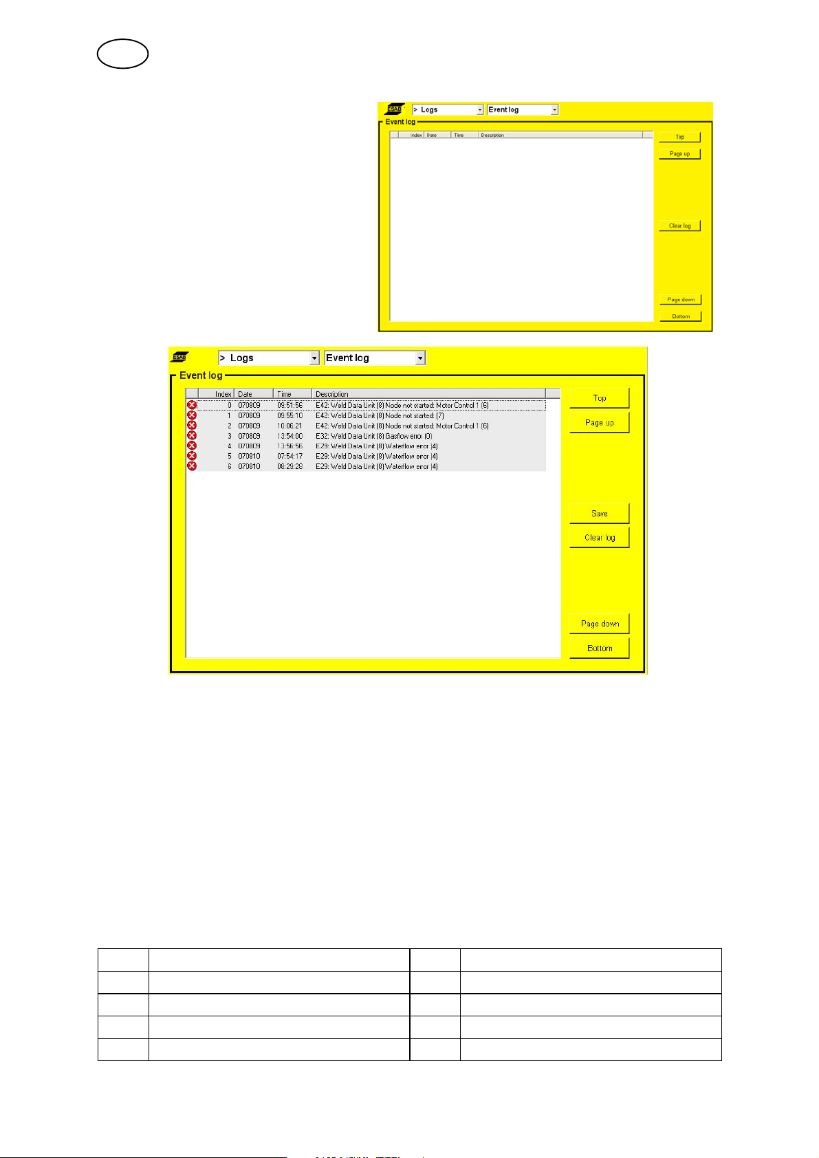
5.8.1 Event log
Event log
When a fault occurs, this is indicated by the symbol , which is displayed to the
right of the ESAB logo. When you go into the Event log menu, the symbol
disappears.
bi16d1ea
- 34 -
© ESAB AB 2007
GB
Used to display operating messages
In order to clear or remove all operating messages from the log, move the focus to
the ”Clear log” button with the arrow keys and press the knob. Confirm that you want
to remove all events by pressing ”Yes” with the knob. The event log is reloaded and
is now empty.
It is also possible to save the event log onto an external USB memory.
Proceed as follows:
S Insert a USB memory in the panel's USB contact, move the focus with the arrow
keys to the ”Save” button.
S Press the knob. The text ”Event log saved” appears in the lower status bar if the
log was saved correctly.
Operating messages
Unit Unit
1 = cooling unit 8 = weld data unit
2 = power source 14 = motor control 2, AVC, oscillation
4 = remote control 17 = I/O node
6 = motor control 1, rotation, wire feed
bi16d1ea
- 35 -
© ESAB AB 2007

GB
Below describes event codes which the user can take action by him self. Is any other
code shown, send for a service technician.
Code Description
5 Intermediate DC voltage outside limits
The voltage is too high or too low. Too high a voltage can be due to severe transients on
the mains power supply or to a weak power supply (high inductance of the supply or a
phase missing).
The power unit is stopped and cannot be started.
Action: Turn off the mains power supply to reset the unit. If the fault persists, send for a
service technician.
6 High temperature
The thermal overload cut-out has tripped.
The current welding process is stopped and cannot be restarted until the cut-out has reset.
Action: Check that the cooling air inlets or outlets are not blocked or clogged with dirt.
Check the duty cycle being used, to make sure that the equipment is not being overloaded.
If the fault is repeated, send for a service technician.
11 Motor servo fault, (rotation, wire feed, oscillation, AVC)
When a motor cannot maintain its speed. Welding stops.
Action: Check that the tool / wire feed unit has not become trapped or is moving too
slowly. Check that the weaving unit's oscillating movement has not reached the outer limit.
If so, adjust the centre position. If the fault persists, send for a service technician.
11 Current servo fault, (power source)
The voltage is too high or too low. Too high a voltage can be due to severe transients on
the mains power supply or to a weak power supply (high inductance of the supply or a
phase missing).
The power unit is stopped and cannot be started.
Action:Turn off the mains power supply to reset the unit. If the fault persists, send for a
service technician.
12 Internal communication error (warning)
The load on the system's CAN-bus is temporarily too high.
The power unit may have lost contact with the panel.
Action: Check that all the equipment is correctly connected.
If the fault persists, send for a service technician.
14 Communication error
The system's CAN-bus has temporarily stopped working due to the load being too high.
The current welding process stops.
Action: Check that all the equipment is correctly connected. Turn off the mains power
supply to reset the unit. If the fault persists, send for a service technician.
17 Lost contact with unit
Lost contact with unit. The gas is not turned off; it must be turned off manually.
Start is prevented
Action: Check the cables. If the fault persists, send for a service technician.
19 Battery voltage low
Battery voltage too low. If the battery is not replaced, all stored data will be lost.
This fault does not disable any functions.
Action: Send for a service technician to replace the battery.
20 Incorrect set values stored in welding program
Non-permitted values have been discovered at start-up.
Action: Change parameters in the welding program. If the fault persists, send for a service
technician.
bi16d1ea
- 36 -
© ESAB AB 2007

GB
Code Description
29 No cooling water flow
The flow monitor switch has tripped.
The current welding process is stopped and starting is prevented.
Action: Check cooling water circuit, pump and hoses.
32 No gas flow
The gas flow is less than 3.5 l/min. Start prevented.
Action: Check the gas valve, hoses and connectors.
41 Failed welding start
The power source does not manage to light the welding arc.
Action: Check welding cables and tool.
5.8.2 Quality data
Here you can view data saved
under the post weld function, see
chapter 5.3.
Logs --> QData --> QData files
The QData file is saved with the
date and a serial number.
The files can be saved to a USB
memory device using ”Save”.
Logs --> QData --> QData content
The QData file's set values and
measurement values are visible in
this field.
bi16d1ea
- 37 -
© ESAB AB 2007
GB
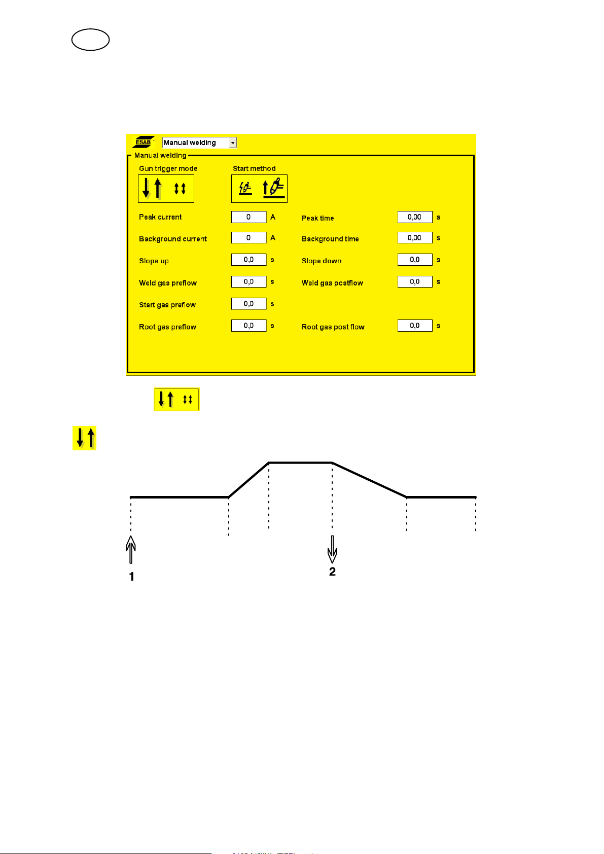
5.9 Manual welding
This menu is used for welding performed with a manual TIG torch.
Trigger mode
2 stroke
Gas preflow Slope
up
Functions when using 2-stroke control of the welding torch.
Slope down Gas postflow
In 2-stroke control mode, pressing the TIG torch trigger switch (1) starts gas preflow
(if used) and ignites the arc. The current rises to the set value (as controlled by the
slope up function, if in operation). Releasing the trigger switch (2) reduces the
current (as controlled by the slope down function, if in operation) and extinguishes
the arc. Gas postflow follows, if in operation.
bi16d1ea
- 38 -
© ESAB AB 2007

GB
4 stroke
Gas preflow Slope
up
Functions when using 4-stroke control of the welding torch.
Slope down Gas postflow
In 4-stroke control mode, pressing the trigger switch (1) starts gas preflow (if used).
At the end of the gas preflow time, the current rises to the pilot level (a few
amperes), and the arc is ignited. Releasing the trigger switch (2) increases the
current to the set value (as controlled by the slope up function, if in operation). When
the trigger switch is next pressed (3), the current is reduced to pilot level again (as
controlled by the slope down function, if in operation). Releasing the switch again (4)
extinguishes the arc and starts gas postflow.
Start method
HF
The HF function ignites the arc by means of a spark produced when the electrode is
brought closer to the workpiece.
LiftArct
The LiftArct function ignites the arc when the electrode is brought into contact with
the workpiece and then lifted away from it.
Igniting the arc using the LiftArc functiont. Step 1: the electrode is held against the workpiece. Step
2: the trigger switch is pressed, and a low current starts to flow. Step 3: the welder lifts the electrode
from the workpiece; the arc ignites, and the current rises automatically to the set value.
bi16d1ea
- 39 -
© ESAB AB 2007

GB
Peak current
The higher of two current values in the event of pulsed current.
Background current
The lower of two current values in the event of pulsed current.
Peak time
The time the pulse current is on during a pulse period.
Background time
Background current time that together with the pulse current time produces the pulse
period.
Pulse time
Background time
Peak current
Background current
TIG welding with pulsed current
Slope up
The slope up function means that when the TIG arc ignites the current rises slowly to
the set value. This provides `gentler' heating of the electrode, and gives the welder a
chance to position the electrode properly before the full current value is reached.
Slope down
TIG welding uses ”slope down”, where the current falls slowly over a controlled time,
to avoid craters and/or cracks in a completed weld.
Gas preflow
This controls the time during which shielding gas flows before the arc is ignited. Also
see information under chapter 3.7.
Gas postflow
This controls the time during which shielding gas flows after the arc is extinguished.
Also see information under chapter 3.7.
bi16d1ea
- 40 -
© ESAB AB 2007

GB
5.10 Generate
A complete basic weld program can be generated here that can be added to the
design area or directly to the weld area. The program can be used as the basis for
creating your own program.
Specify:
S Tube material
S Tube wall thickness
Max. 3 mm for stainless steel and max. 2.7 mm for carbon steel.
S External tube diameter
S Tool and tool type
Activate by pressing ”Generate in weld area” or ”Generate in design area”.
Automatically opens the weld area or design area menu.
It is now possible to continue working on the program in the weld area or design
area. See chapter ”Weld Area” 5.1 or ”Design Area” 5.2.
bi16d1ea
- 41 -
© ESAB AB 2007

6 TECHNICAL TERMS
2 stroke 2-stroke control of the welding torch.
4 stroke 4-stroke control of the welding torch.
Amplitude Weave.
Arc voltage
control, AVC
Background current The lower of two current values when using pulsed current.
Background time Background current time that together with the peak current time produces
Background voltage Arc voltage control when using background current.
Background wire feed
speed
Breakpoint Starting point for a new sector.
Delay time The time it takes for the arc voltage to stabilize before arc voltage control
Design area Weld programs are created in this menu.
End sector Last welding sector in a welding sequence.
Generate Search for a complete basic weld program.
Library Memory for storing weld programs.
Peak current The higher of two current values when using pulsed current, or the current
Peak voltage Arc voltage control at peak current.
Peak wire feed speed Wire feed speed at peak current.
Preheating time Delay time for welding movement when preheating the workpiece.
Pulse time The time the current is ”on” during a pulse period.
Root gas Shielding gas for the underside of the weld joint (root side).
Rotation speed The rotation speed of the electrode around the workpiece.
Sector A specific section of tube.
Sector system How the division into sectors is displayed, by degrees or breakpoints.
Slope down Gradual reduction of a value.
Slope up Gradual increase in a value.
Special pulsing Welding current synchronizes with the weaving motion.
Square-wave pulsing Special pulsing with pulsed rotation.
Start gas Special shielding gas with high ionizing qualities, which facilitates arc
Start sector First welding sector in a welding sequence.
Verify Check whether the program stays within the limit values.
Weaving Weave tungsten electrode sideways.
Weld area Programs in the weld area control the welding process.
Weld gas Shielding gas for the upper side of the weld joint.
Automatic regulation of the electrode distance.
the pulse period.
Wire feed speed during specified background time.
begins.
value when using continuous current.
ignition.
bi16d1eb
- 42 -
© ESAB AB 2007

WO100
4
Ordering number
Ordering no. Denomination
0444 405 070 Instruction manual SE
0444 405 071 Instruction manual DK
0444 405 072 Instruction manual NO
0444 405 073 Instruction manual FI
0444 405 074 Instruction manual GB
0444 405 075 Instruction manual DE
0444 405 076 Instruction manual FR
0444 405 077 Instruction manual NL
0444 405 078 Instruction manual ES
0444 405 079 Instruction manual IT
0444 405 080 Instruction manual PT
0444 405 081 Instruction manual GR
0444 405 082 Instruction manual PL
0444 405 083 Instruction manual HU
0444 405 084 Instruction manual CZ
0444 405 086 Instruction manual RU
Instruction manuals and the spare parts list are available on the Internet at www.esab.com
- 43 -
bi16o4
© ESAB AB 2007

NOTES
.............................................................................................................................................................
.............................................................................................................................................................
.............................................................................................................................................................
.............................................................................................................................................................
.............................................................................................................................................................
.............................................................................................................................................................
.............................................................................................................................................................
.............................................................................................................................................................
.............................................................................................................................................................
.............................................................................................................................................................
.............................................................................................................................................................
.............................................................................................................................................................
.............................................................................................................................................................
.............................................................................................................................................................
.............................................................................................................................................................
.............................................................................................................................................................
.............................................................................................................................................................
.............................................................................................................................................................
.............................................................................................................................................................
.............................................................................................................................................................
.............................................................................................................................................................
.............................................................................................................................................................
.............................................................................................................................................................
.............................................................................................................................................................
.............................................................................................................................................................
.............................................................................................................................................................
.............................................................................................................................................................
.............................................................................................................................................................
.............................................................................................................................................................
.............................................................................................................................................................
.............................................................................................................................................................
- 44 -
notes
© ESAB AB 2007

NOTES
.............................................................................................................................................................
.............................................................................................................................................................
.............................................................................................................................................................
.............................................................................................................................................................
.............................................................................................................................................................
.............................................................................................................................................................
.............................................................................................................................................................
.............................................................................................................................................................
.............................................................................................................................................................
.............................................................................................................................................................
.............................................................................................................................................................
.............................................................................................................................................................
.............................................................................................................................................................
.............................................................................................................................................................
.............................................................................................................................................................
.............................................................................................................................................................
.............................................................................................................................................................
.............................................................................................................................................................
.............................................................................................................................................................
.............................................................................................................................................................
.............................................................................................................................................................
.............................................................................................................................................................
.............................................................................................................................................................
.............................................................................................................................................................
.............................................................................................................................................................
.............................................................................................................................................................
.............................................................................................................................................................
.............................................................................................................................................................
.............................................................................................................................................................
.............................................................................................................................................................
.............................................................................................................................................................
- 45 -
notes
© ESAB AB 2007

ESAB subsidiaries and representative offices
Europe
AUSTRIA
ESAB Ges.m.b.H
Vienna-Liesing
Tel: +43 1 888 25 11
Fax: +43 1 888 25 11 85
BELGIUM
S.A. ESAB N.V.
Brussels
Tel: +32 2 745 11 00
Fax: +32 2 745 11 28
BULGARIA
ESAB Kft Representative Office
Sofia
Tel/Fax: +359 2 974 42 88
THE CZECH REPUBLIC
ESAB VAMBERK s.r.o.
Vamberk
Tel: +420 2 819 40 885
Fax: +420 2 819 40 120
DENMARK
Aktieselskabet ESAB
Herlev
Tel: +45 36 30 01 11
Fax: +45 36 30 40 03
FINLAND
ESAB Oy
Helsinki
Tel: +358 9 547 761
Fax: +358 9 547 77 71
FRANCE
ESAB France S.A.
Cergy Pontoise
Tel: +33 1 30 75 55 00
Fax: +33 1 30 75 55 24
GERMANY
ESAB GmbH
Solingen
Tel: +49 212 298 0
Fax: +49 212 298 218
GREAT BRITAIN
ESAB Group (UK) Ltd
Waltham Cross
Tel: +44 1992 76 85 15
Fax: +44 1992 71 58 03
ESAB Automation Ltd
Andover
Tel: +44 1264 33 22 33
Fax: +44 1264 33 20 74
HUNGARY
ESAB Kft
Budapest
Tel: +36 1 20 44 182
Fax: +36 1 20 44 186
ITALY
ESAB Saldatura S.p.A.
Bareggio (Mi)
Tel: +39 02 97 96 8.1
Fax: +39 02 97 96 87 01
NORWAY
AS ESAB
Larvik
Tel: +47 33 12 10 00
Fax: +47 33 11 52 03
POLAND
ESAB Sp.zo.o.
Katowice
Tel: +48 32 351 11 00
Fax: +48 32 351 11 20
PORTUGAL
ESAB Lda
Lisbon
Tel: +351 8 310 960
Fax: +351 1 859 1277
ROMANIA
ESAB Romania Trading SRL
Bucharest
Tel: +40 316 900 600
Fax: +40 316 900 601
RUSSIA
LLC ESAB
Moscow
Tel: +7 (495) 663 20 08
Fax: +7 (495) 663 20 09
SLOVAKIA
ESAB Slovakia s.r.o.
Bratislava
Tel: +421 7 44 88 24 26
Fax: +421 7 44 88 87 41
SPAIN
ESAB Ibérica S.A.
Alcalá de Henares (MADRID)
Tel: +34 91 878 3600
Fax: +34 91 802 3461
SWEDEN
ESAB Sverige AB
Gothenburg
Tel: +46 31 50 95 00
Fax: +46 31 50 92 22
ESAB international AB
Gothenburg
Tel: +46 31 50 90 00
Fax: +46 31 50 93 60
SWITZERLAND
ESAB AG
Dietikon
Tel: +41 1 741 25 25
Fax: +41 1 740 30 55
UKRAINE
ESAB Ukraine LLC
Kiev
Tel: +38 (044) 501 23 24
Fax: +38 (044) 575 21 88
North and South America
ARGENTINA
CONARCO
Buenos Aires
Tel: +54 11 4 753 4039
Fax: +54 11 4 753 6313
BRAZIL
ESAB S.A.
Contagem-MG
Tel: +55 31 2191 4333
Fax: +55 31 2191 4440
CANADA
ESAB Group Canada Inc.
Missisauga, Ontario
Tel: +1 905 670 02 20
Fax: +1 905 670 48 79
MEXICO
ESAB Mexico S.A.
Monterrey
Tel: +52 8 350 5959
Fax: +52 8 350 7554
USA
ESAB Welding & Cutting Products
Florence, SC
Tel: +1 843 669 44 11
Fax: +1 843 664 57 48
Asia/Pacific
CHINA
Shanghai ESAB A/P
Shanghai
Tel: +86 21 2326 3000
Fax: +86 21 6566 6622
INDIA
ESAB India Ltd
Calcutta
Tel: +91 33 478 45 17
Fax: +91 33 468 18 80
INDONESIA
P.T. ESABindo Pratama
Jakarta
Tel: +62 21 460 0188
Fax: +62 21 461 2929
JAPAN
ESAB Japan
Tokyo
Tel: +81 45 670 7073
Fax: +81 45 670 7001
MALAYSIA
ESAB (Malaysia) Snd Bhd
USJ
Tel: +603 8023 7835
Fax: +603 8023 0225
SINGAPORE
ESAB Asia/Pacific Pte Ltd
Singapore
Tel: +65 6861 43 22
Fax: +65 6861 31 95
SOUTH KOREA
ESAB SeAH Corporation
Kyungnam
Tel: +82 55 269 8170
Fax: +82 55 289 8864
UNITED ARAB EMIRATES
ESAB Middle East FZE
Dubai
Tel: +971 4 887 21 11
Fax: +971 4 887 22 63
Africa
EGYPT
ESAB Egypt
Dokki-Cairo
Tel: +20 2 390 96 69
Fax: +20 2 393 32 13
SOUTH AFRICA
ESAB Africa Welding & Cutting Ltd
Durbanvill 7570 - Cape Town
Tel: +27 (0)21 975 8924
Distributors
For addresses and phone
numbers to our distributors in
other countries, please visit our
home page
www.esab.com
THE NETHERLANDS
ESAB Nederland B.V.
Amersfoort
Tel: +31 33 422 35 55
Fax: +31 33 422 35 44
www.esab.com
110426© ESAB AB
 Loading...