

Page 1
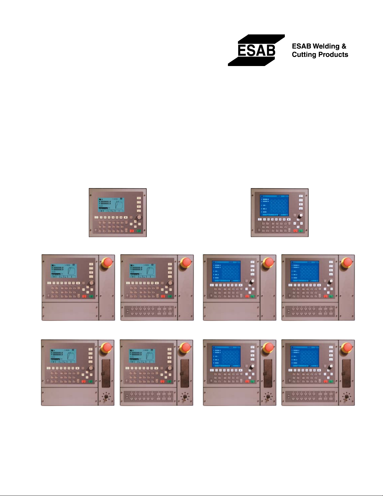
Vision LE
Computer Numerical Control
Start-up Manual
LE-Basic Module
LE-S LE-F
LE-X LE-FX
LE-Color Basic Module
LE-CS LE-CF
LE-CX LE-CFX
Form Number 0558005197
Date: 10/04
Start-up
Page 2

The equipment described in this manual is
potentially hazardous. Use caution when installing,
operating and maintaining this equipment.
The purchaser is solely responsible for the safe
operation and use of all products purchased,
including compliance with OSHA and other
government standards. ESAB Cutting Systems
has no liability for personal injury or other
damage arising out of the use of any product
manufactured or sold by ESAB. See standard
ESAB terms and conditions of sale for a specifi c
statement of ESAB’s responsibilities and
limitations on its liability.
ESAB Cutting Systems is not responsible for
any errors that may appear in this document.
Information in this document is subject to change
without notice.
This manual is ESAB Part No. 0558005197
This manual is for the convenience and use of the
cutting machine purchaser. It is not a contract
or other obligation on the part of ESAB Cutting
Systems.
* ESAB Cutting Systems, 2004
Printed In U.S.A.
Page 3

'MB(
Preface
There are optional features and confi gurations
available. For completeness, all of these are
described in this manual. However, not all options
described in this manual are present on all controls.
In addition, more capabilities and features may be
added in the future, which are not covered in this
manual. ESAB Cutting Systems reserves the right
to change or add features and capabilities without
notice.
Page 4

VISION LE
Startup
Contents Page 2
Contents
1 Introduction.....................................................................................................1
2 Safety .............................................................................................................2
2.1 Safety Precautions .......................................................................................2
2.2 Danger Warnings ..........................................................................................3
2.3 Accident Prevention......................................................................................3
2.4 Emergency Measures ...................................................................................5
2.5 Application and Usage Conditions .................................................................5
3 Startup Window ...............................................................................................6
3.1 Constant Editor ............................................................................................9
3.2 Parameters of Intelligent Stations ............................................................... 13
3.3 Speed Measurement and Display of Rotational Speed .................................18
3.4 Creating a Copy of the System ................................................................... 22
3.5 Formatting a floppy disk............................................................................. 24
3.6 Startup Help ............................................................................................... 26
3.6.1 Determining Working Ranges ................................................................ 28
3.6.2 Setting the Machine Zero Point ..............................................................30
3.6.3 Measuring Tool Offsets ......................................................................... 31
4 Service Window ............................................................................................ 32
4.1 Deviation Display....................................................................................... 33
4.2 LCD Contrast Setting and Testing ............................................................... 34
4.3 MIP Signal Display ..................................................................................... 35
4.4 AF-KF Control............................................................................................37
4.5 Display of Synchronization Errors............................................................... 38
4.6 Mini Operating System ............................................................................... 39
4.7 Error - Status Display.................................................................................41
5 System of the VISION LE .............................................................................. 46
5.1 Files of the internal memory....................................................................... 46
5.2 System Constants ...................................................................................... 48
5.3 Machine constants (MAS.KON) ................................................................... 58
5.4 MIP Constants (MIP.KON) .......................................................................... 69
5.5 Device Constants (DEV.KON) ..................................................................... 74
5.6 Configuration (ANCDEF.KON) ..................................................................... 78
6 Error Messages (Codes of Disk Errors).......................................................... 80
7 Symbol Overview .......................................................................................... 83
7.1 Startup window ........................................................................................... 83
7.2 Deviation Display / LCD Test (Shift/F1).......................................................86
7.3 MIP Signal Display (Shift/F2)......................................................................87
7.4 AF/KF Control (Shift/F3)............................................................................. 88
7.5 Synchronization Display (Shift/F4) .............................................................. 89
7.6 Mini Operating System (Shift/F5) ................................................................ 90
8 Index............................................................................................................ 91
41&63A0204 (vision_le_m_us_inb.doc )
Page 5

VISION LE
Startup
Safety Page 1
1 Introduction
VISION LE is a numeric contouring control system especially designed for the use with flame-cutting
machines.
Note
Since the various types of the VISION-LE control differ in their functional range it can occur that not
all functions described in this manual are availlable on each specific control.
41&63A0204 (vision_le_m_us_inb.doc )
Page 6

VISION LE
Startup
Safety Page 2
2 Safety
For your own safety, please heed the safety precautions
and danger warnings given in this section!
2.1 Safety Precautions
I.
A copy of this safety-related information shall be provided
to the operating pe rsonnel.
II.
In order to safely operate the control system, it is
necessary to have read and understood the operating
manual provided with the cutting machine. The operating
personnel must be properly trained under all
circumstances.
III.
All applicable safety guidelines and specifications for the
"electrical equipment" on machines and auxiliary
equi pment as well as operating devices must be heeded.
IV.
With regard to flame-cutting, the accident prevention
guideline "Welding, cutting and related work operations"
applies (UVV VBG 15).
V.
In order to prevent the entry of non-authorized persons
into the operating area of the machine, the operator must
carry out, where necessary, suitable safety precautions for
eliminating hazards in accordance with UVV VBG 5, e.g. as
safety fencing as per DIN 24533, Danger signs.
41&63A0204 (vision_le_m_us_inb.doc )
Page 7
VISION LE
Startup
Safety Page 3
2.2 Danger Warnings
I.
When installing the control system on the cutting machine
as well as the auxiliary equipment, the prescribed
connection voltage and particularly the proper co nnection
of the ground conductor must be checked.
II.
Test and repair work shall be performed exclusively by
trained technical personnel.
III.
Only original spare parts shall be used for the electrical
equipment.
IV.
Do not weld on the cutting machine!
V.
You must heed the danger warnings in the machine
manual!
2.3 Accident Prevention
I.
The door to the control system should be kept closed
under normal circumstances in order to avoid dust
accumulation and to protect the operating personnel from
accidentally touching the electrical equipment. The control
system shall be opened only by technical personnel.
Protective devices shall not be modified. Fuses shall not
be jumpered, nor shall their characteristics be modified.
II.
When working with grounded test equipment such as an
oscilloscope, make ce rtain that the grounding jack of the
test equipment is always connected to the ground point of
the control system (test cable). If necessary, use an
isolation amplifier for floating measurements.
41&63A0204 (vision_le_m_us_inb.doc )
Page 8

VISION LE
Startup
Safety Page 4
III.
When working with live circuits, e.g. during test and
alignment work, you should exercise great caution. It is
wise to have a helper stand in the vicinity of the machine's
MAIN POWER switch so that the power can be cut off
immediately in case of an emergency.
VI.
If at all possible, work on the electrical equipment should
be performed only when the machine has been switched
off. During such work, make certain that the power switch
cannot be flipped on (e.g. hang a safety lock).
V.
During the following work, the system or parts thereof
must be switched off:
When the work is completed or during longer interruptions
in the work, power down the MAIN POWER switch of the
machine as well as the auxiliary equipment.
VI.
If any cables, connectors or electrical devices are
damaged, immediately power down the MAIN POWER
switch of the machine. The damaged parts must be
repaired by trained technical personnel.
VII.
Boards or connections may be removed only when the
machine is switched off. Avoid mixing up boards or
connections --> Read the label or code. In case of doubt,
refer to the documentation or ask someone who knows.
VIII.
Please heed the following guidelines as well:
Connection conditions of the power company
OSHA safety guidelines
IEC safety guidelines
Safety precautions in operating manuals for the various
work procedures, such as oxy-fuel cutting, plasma cutting,
etc.
41&63A0204 (vision_le_m_us_inb.doc )
Page 9

VISION LE
Startup
Safety Page 5
2.4 Emergency Measures
If the machine or control system catches on fire, only use
carbon dioxide (CO2) or a suitable powder to extinguish
the fire!
If your clothes catch on fire, do not run away!
Lie on the ground and roll around to extinguish the
flames, or use fire-extinguishing blankets.
2.5 Application and Usage Conditions
This control system is a component of a machine and may
be used only for this machine.
Only those applications are allowed which the operating
manual of the respective machine expressly permits.
See the appropriate machine description for the allowable
ambient conditions for operating this control system.
For safety reasons, do not attempt to modify, upgrade, or
enhance the control system.
41&63A0204 (vision_le_m_us_inb.doc )
Page 10
VISION LE
Startup
Startup Window Page 6
3 Startup Window
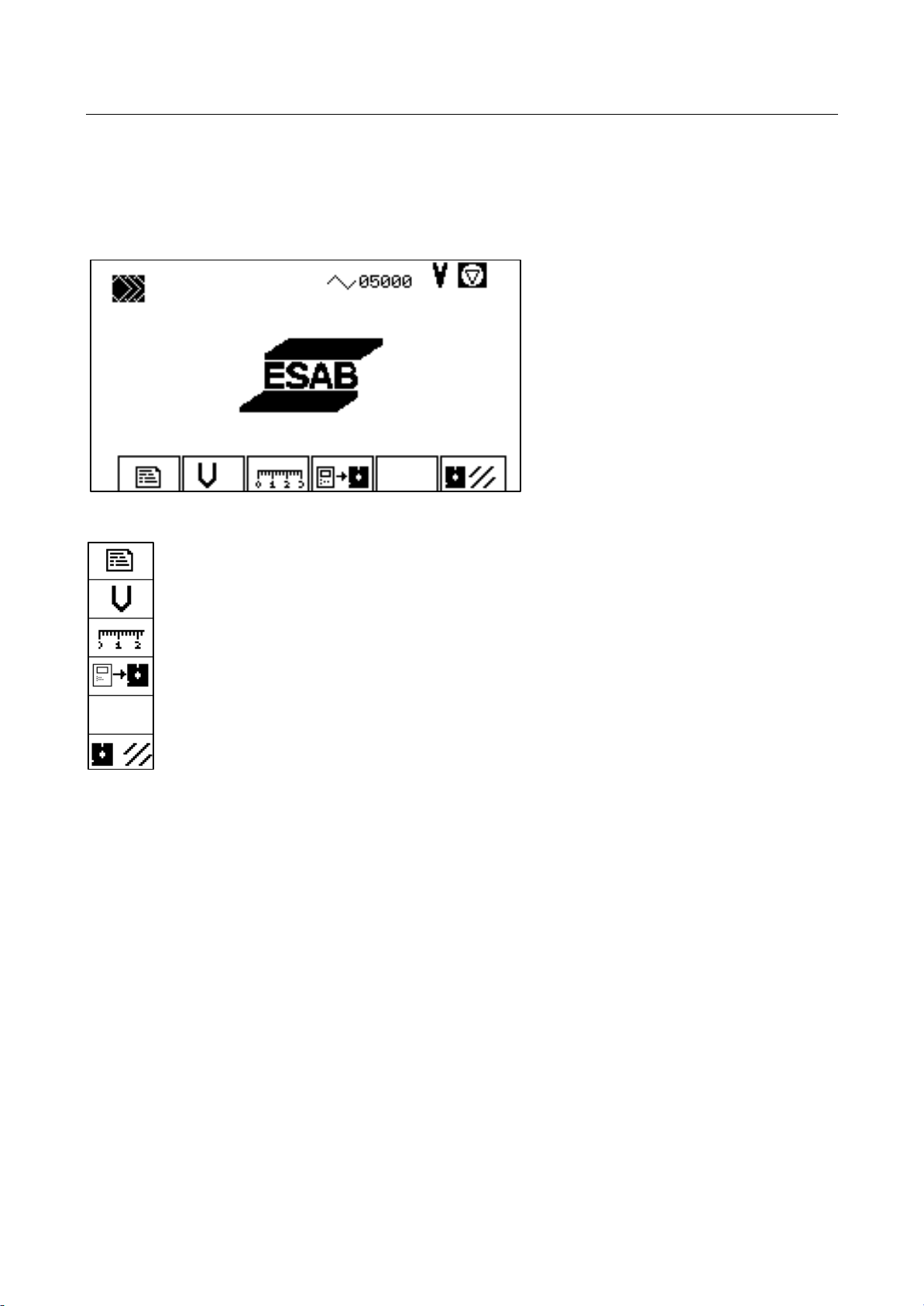
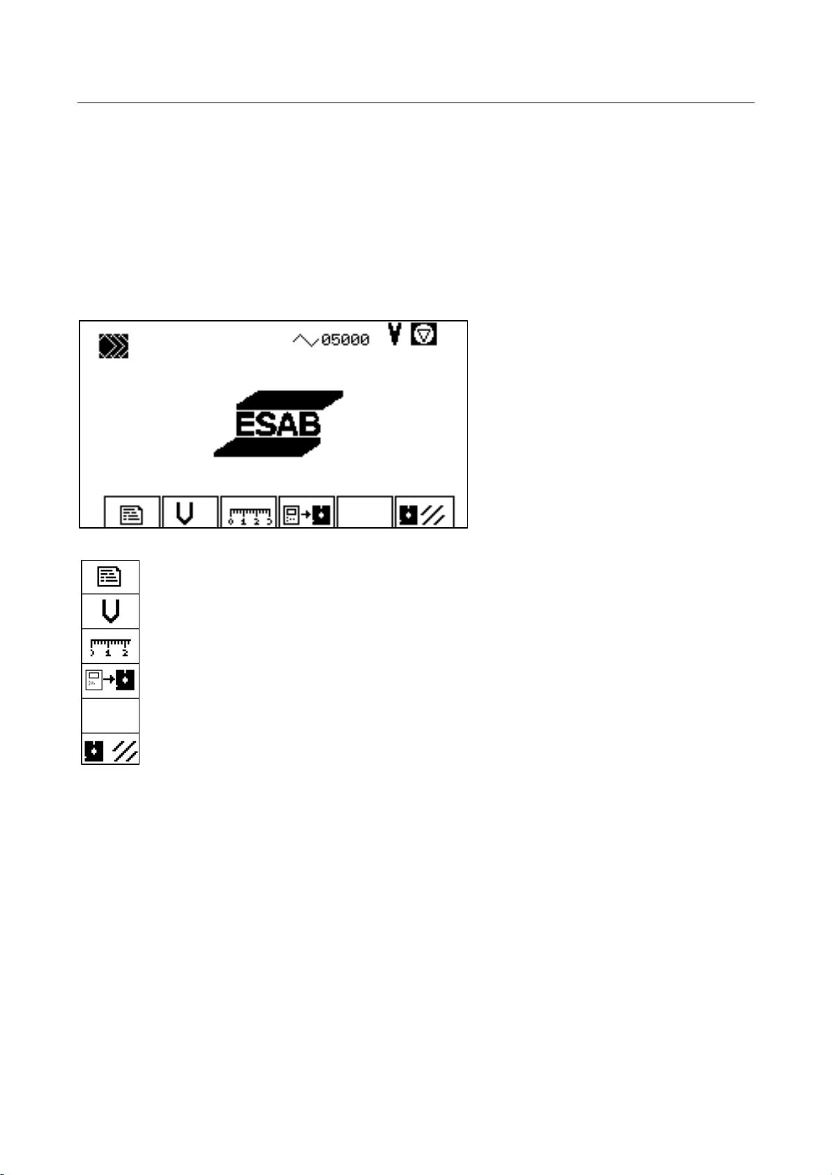
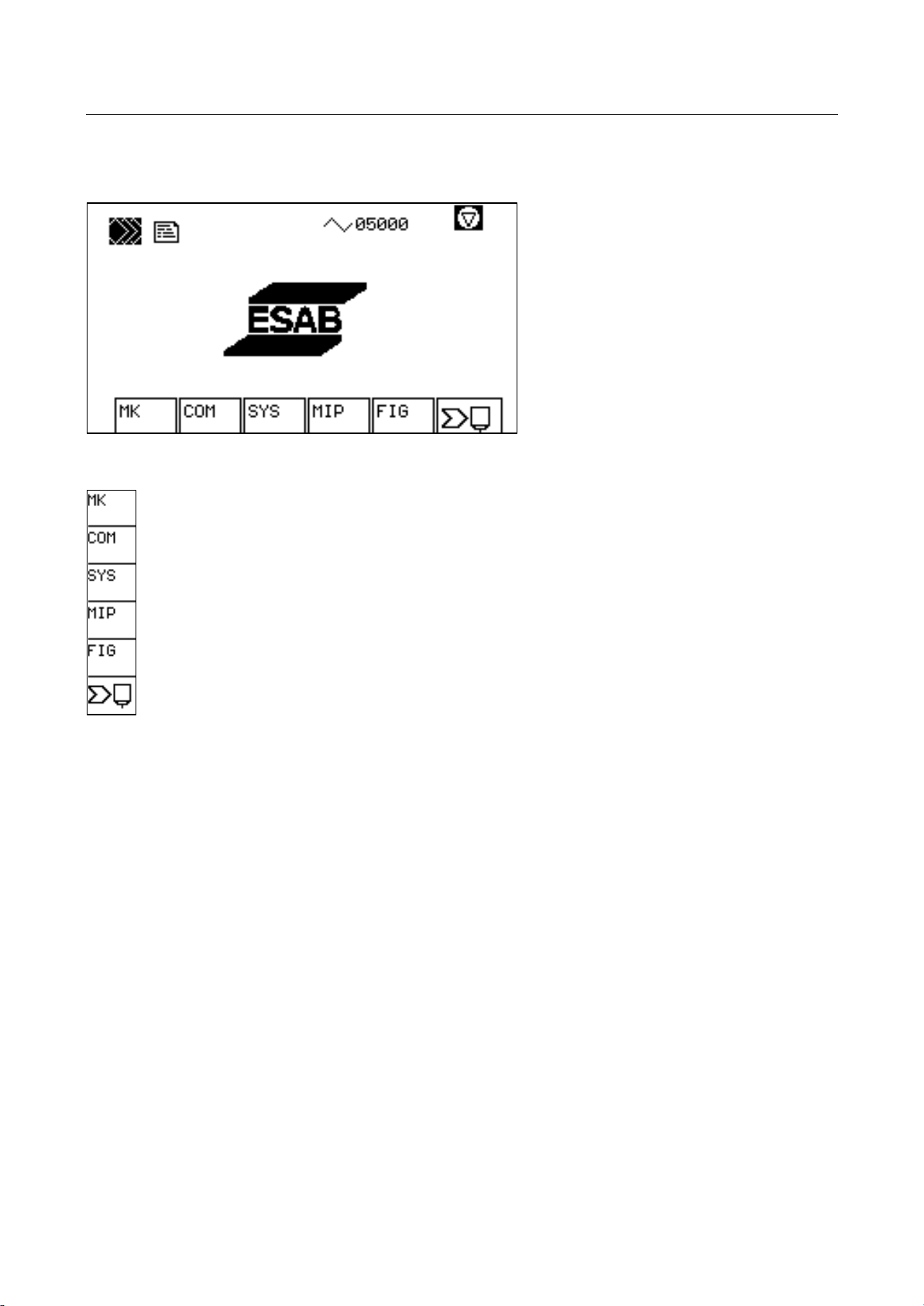
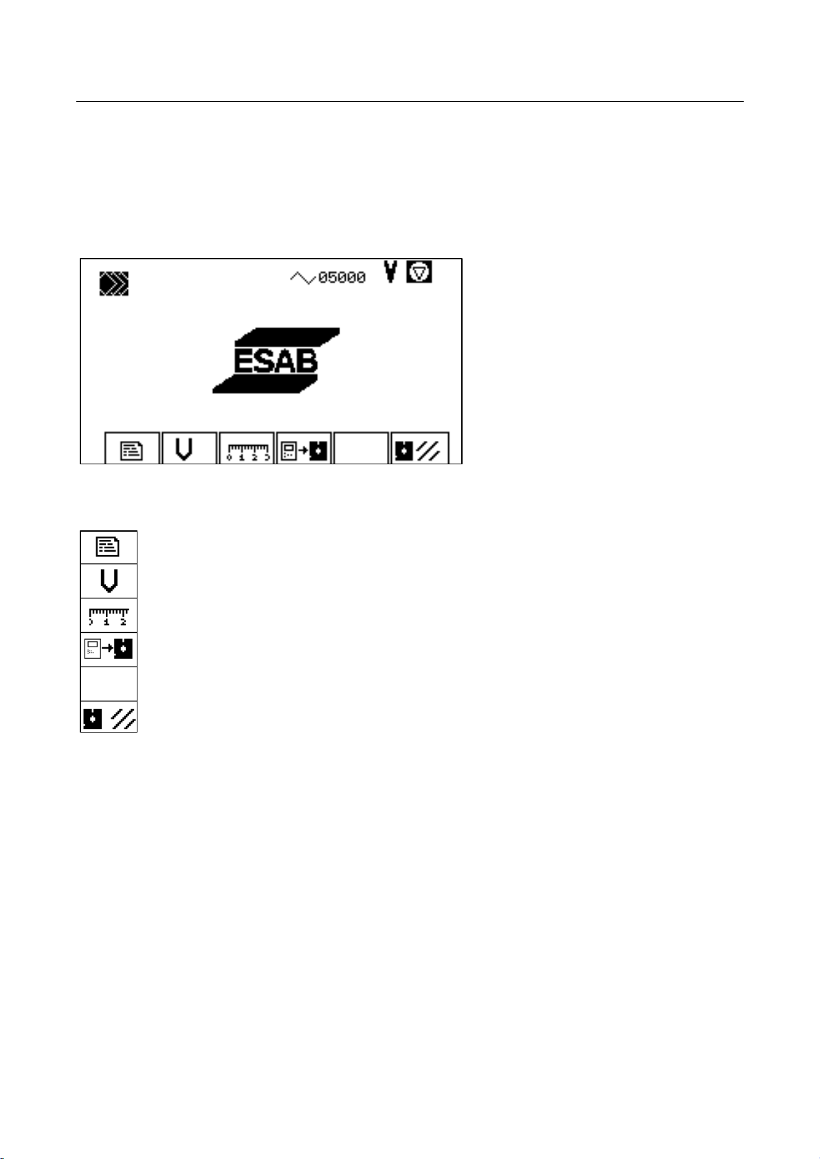
This window contains all the functions for starting up the control.
Constant editor.
Speed startup.
Startup help.
Copy system files
Format floppy disk.
Constant Editor
For editing machine constants (page 9 )
For editing device constants (page 9 )
For editing system constants (page 9)
For editing MIP constants (page 9)
For editing the configuration (page 9)
For editing station constants (page 13)
Speed Startup
For determining the axis speed (page 13)
Rotational speed display (page 20)
41&63A0204 (vision_le_m_us_inb.doc )
Page 11

VISION LE
Startup
Startup Window Page 7
Startup Help
For adjusting working ranges (page 28)
For defining the machine zero point (page 30)
For determining tool offsets (page 31)
Creating A System Floppy
For creating a backup copy of the system floppy disk (page 22)
Formatting A Floppy (page 24)
41&63A0204 (vision_le_m_us_inb.doc )
Page 12
VISION LE
Startup
Startup Window Page 8
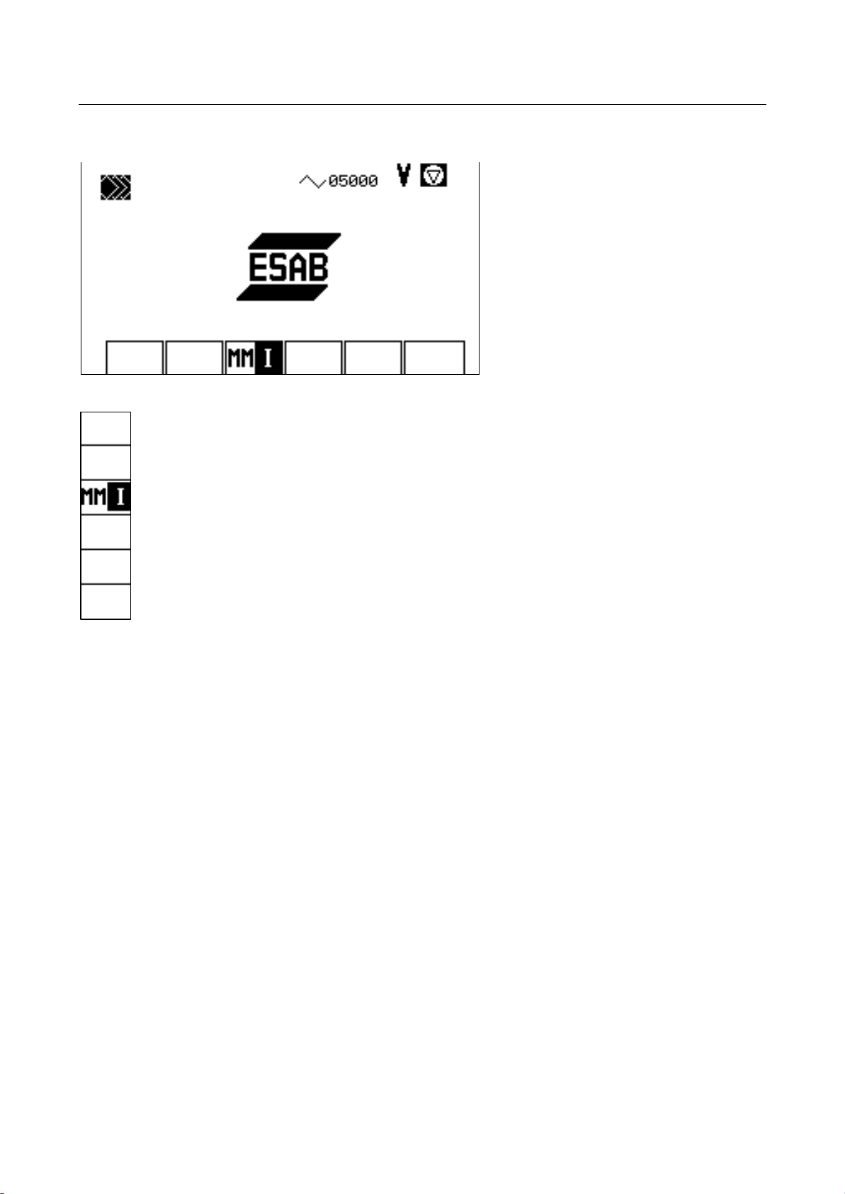
More Key of the Startup Window
MM/Inch conversion
41&63A0204 (vision_le_m_us_inb.doc )
Page 13
VISION LE
Startup
Startup Window Page 9
3.1 Constant Editor
The control is adapted to the environment such as machine and communication by means of various
constants and parameters. Constants and parameters are filed in the internal memory.
Setting of the constants is done once during startup.
The description of the constants regarding content starts on page 46.
Constant editor. (page 10)
Speed startup.
Startup help.
Copy system files
Format floppy disk.
41&63A0204 (vision_le_m_us_inb.doc )
Page 14
VISION LE
Startup
Startup Window Page 10
Selecting Constants
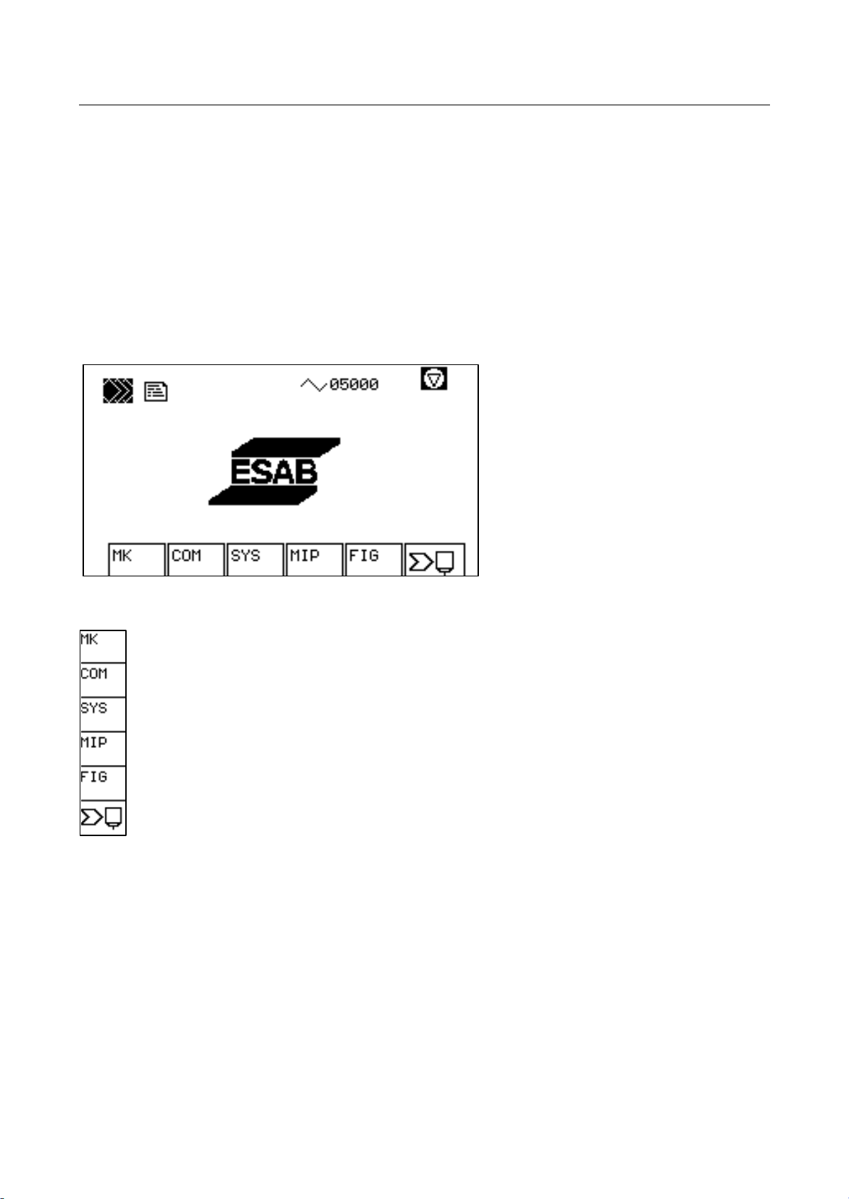
The constants are divided into five groups:
- Machine constants for moving the machine
- Device constants for external devices
- System adaption
- MIP constants
- System - configuration constants (only display)
- Parameters of the stations
Machine constants (page 58)
Device constants (page 74)
System constants (page 48)
MIP constants (page 69)
Configuration constants - cannot be changed (page 78)
Station parameters (page 13)
41&63A0204 (vision_le_m_us_inb.doc )
Page 15
VISION LE
Startup
Startup Window Page 11
Editing Constants - Machine Constants: An Example
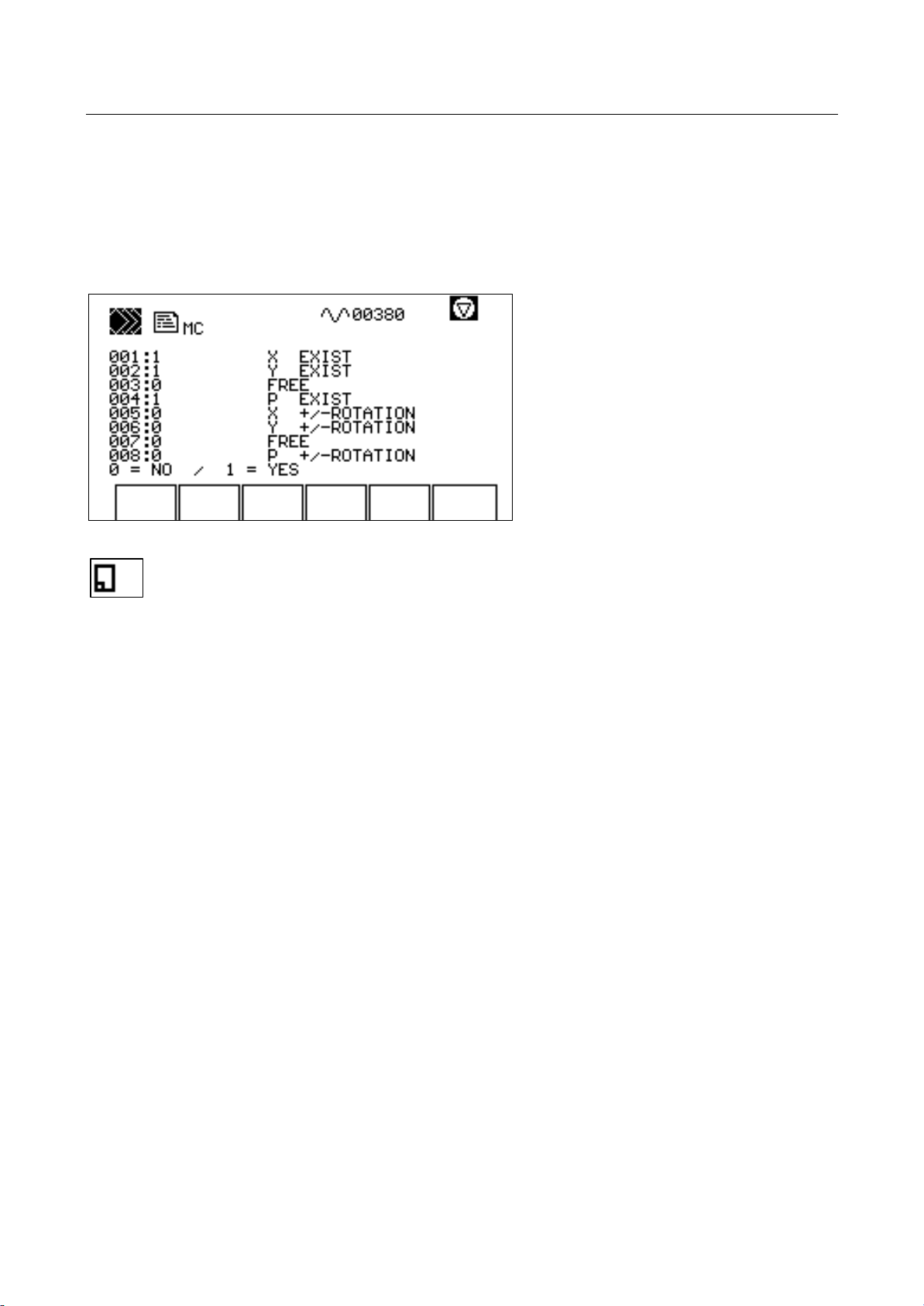
All constants and parameters are treated the same way. The representation of constants and their
alteration is shown for the machine constants as an example. Device, system, and MIP constants are
treated the same way. The configuration constants cannot be changed.
Constants can only be edited in the service mode.
End editing procedure. If changes have been made, the changed constants will be
adopted in the internal memory.
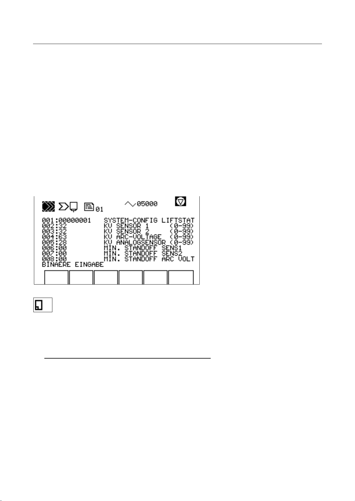
The identification character is in the top line, indicating which constants are dealt with. The symbols
are taken from the preceding menu.
The following eight lines list, in extracts, eight of the constants at a time.
The numbers followed by the colon are firmly assigned to the constants. It is possible that constants
are summarized according to different aspects in the column machine constants. In this case, the
numbers are not longer sequential.
The colon is followed by the actually set parameter. Place and meaning of the digits are defined per
constant.
The remaining part of the line is the description of the parameter. The description does not have any
further effect.
The constant that is to be edited in this window, can be selected with the cursor keys.
41&63A0204 (vision_le_m_us_inb.doc )
Page 16

VISION LE
Startup
Startup Window Page 12
The bottom line shows the type of entry and the scope per constant.
Text Character Set
0=NO / 1=YES 0 and 1
Decimal entry from <n> to <n>, with signs 0 to 9, +/Positive entry from <n> to <n> 0 to 9
Hexadecimal entry 0 to F
Binary entry 0 and 1
No entry
Every entry is checked to find out whether the value is within the scope. If necessary, it is limited to
the maximum value. No entry indicates that these constants cannot be changed.
41&63A0204 (vision_le_m_us_inb.doc )
Page 17
VISION LE
Startup
Startup Window Page 13
3.2 Parameters of Intelligent Stations
Stations are adapted to their tasks by means of parameters The parameters of the stations are
edited on the control and then loaded at the stations.
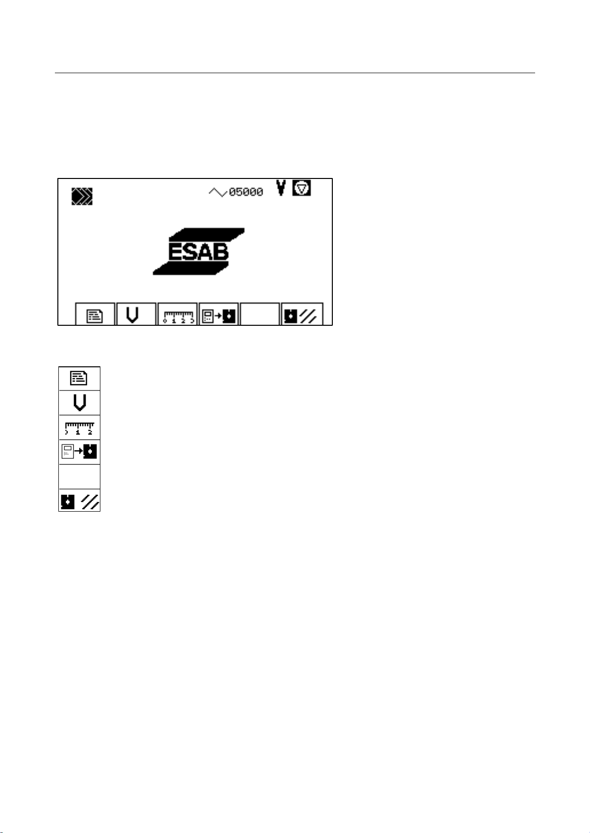
Constant editor (page 9)
Speed startup
Startup help.
Copy system files
Format floppy disk
41&63A0204 (vision_le_m_us_inb.doc )
Page 18
VISION LE
Startup
Startup Window Page 14
Selecting Constant Editor
Machine constants
Device constants
System constants
MIP constants
Configuration
Station parameters (see next page)
41&63A0204 (vision_le_m_us_inb.doc )
Page 19
VISION LE
Startup
Startup Window Page 15
Station Parameters
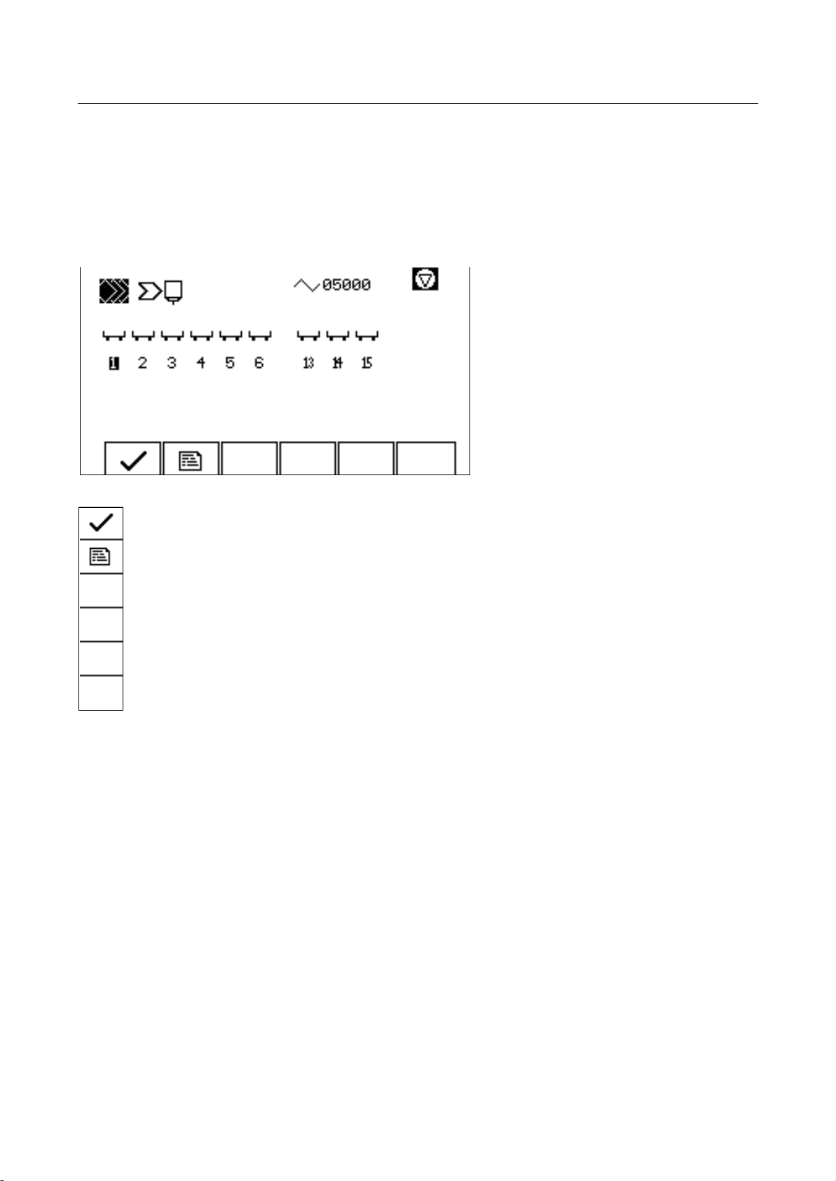
The station whose parameters are to be changed, is selected with the cursor keys.
The machines are designed for a maximum of six stations (burner holders). The "stations" 13, 14 and
15 are actually not real stations. Parameters for central tasks are filed here.
Send parameters to selected station (see next page)
Edit parameters of selected station (page 17)
41&63A0204 (vision_le_m_us_inb.doc )
Page 20
VISION LE
Startup
Startup Window Page 16
Sending Parameters To Selected Station
Parameters are only sent to a station if this station supports a process, i.e. the first station constant
(SYSTEM CONFIG LIFTSTATION) indicates whether and if yes, which process the corresponding
station supports. If the value is 0, the station does not support a process.
In case of successful sending (positive station response), a so-called derivation for this station takes
place. The station is added to the process screens. The process that the station supports is activated
so that it can be preselected and launched.
If this function is executed for a station that does not support any process (first station constant = 0,
or no constant file is available for this station) only the above mentioned derivation (no sending) will
take place. If the station was visible on the screen. it is made invisible. If the process that the station
supported, is not available on any other station, it is deactivated (the process can no longer be
preselected and launched).
Editing Parameters
The description of the constants regarding content starts on page 46.
End editing procedure
The bottom line shows the type of entry and the scope per constant.
Text Character Set
0=NO / 1=YES 0 and 1
Decimal entry from <n> to <n> +, -, 0 to 9
Positive entry from <n> to <n> 0 to 9
Hexadecimal entry 0 to F
Binary entry 0 and 1
No entry
The constant that is to be edited in this window, can be selected with the cursor keys.
Every entry is checked to find out whether the value is within the scope. If necessary, it is limited to
the maximum value.
41&63A0204 (vision_le_m_us_inb.doc )
Page 21

VISION LE
Startup
Startup Window Page 17
When the changes have been adopted, the data is stored and then sent automatically to the
corresponding station.
41&63A0204 (vision_le_m_us_inb.doc )
Page 22
VISION LE
Startup
Startup Window Page 18
3.3 Speed Measurement and Display of Rotational Speed
For the position control of the system, it is important that the speed of the individual axes is
determined and defined as precise as possible.
Constant editor
Speed startup (only in service mode) (page 19)
Startup help
Copy system files
Format floppy disk
41&63A0204 (vision_le_m_us_inb.doc )
Page 23

VISION LE
Startup
Startup Window Page 19
Speed Startup
The axes speeds are measured in this window.
Measure axis speed of X-axis
Measure axis speed of Y-axis
Display rotational speed (page 20)
The speed measurement in one of the two axis "X" or "Y" is started by pressing the corresponding
menu key. The machine axis is moved a little bit at 1/10 of the nominal speed. In view of the
measuring time, the distance covered this way is converted into an axis speed.
The start symbol is displayed immediately and disappears after the measurement has been
completed. After measurement, the display shows the determined maximum speed of the axis.
For portal machines, the speeds for both portal axes are measured and displayed simultaneously.
Adopt measured values in machine constants
41&63A0204 (vision_le_m_us_inb.doc )
Page 24
VISION LE
Startup
Startup Window Page 20
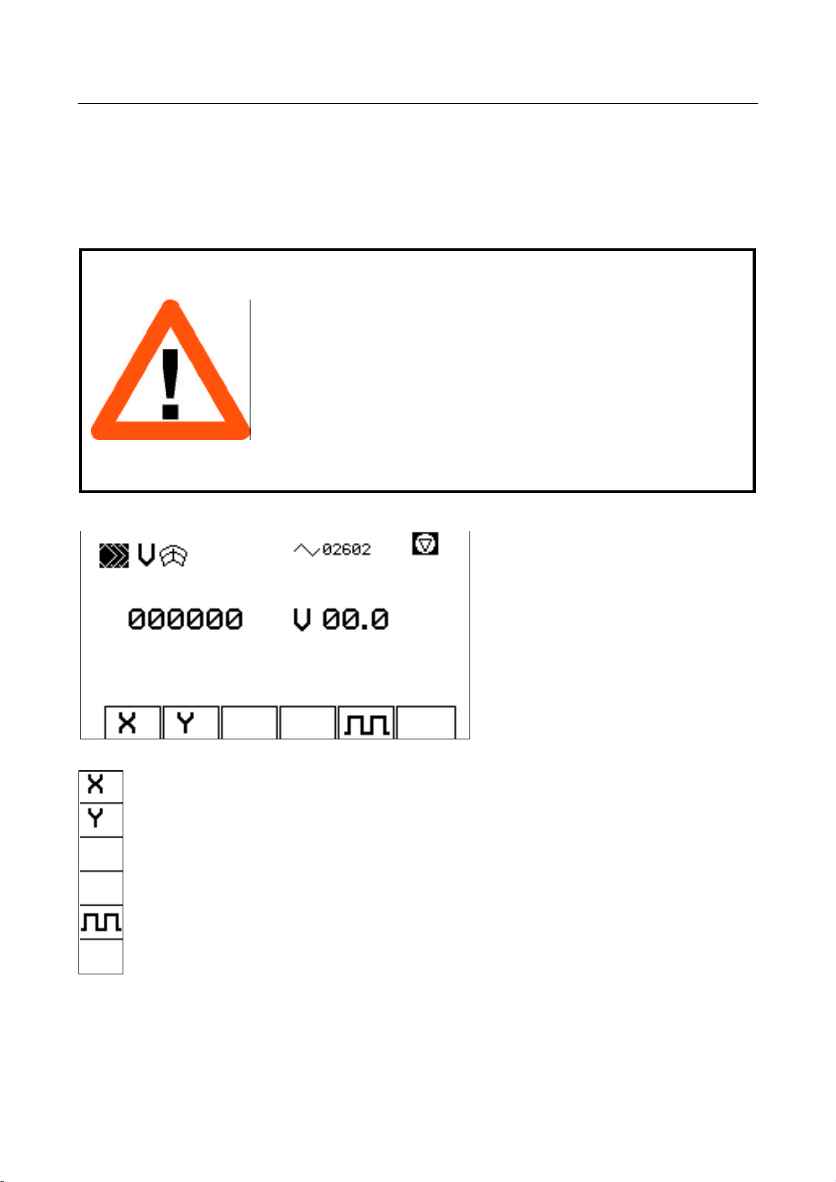
Rotational Speed Display
In case of different values during speed measurement, the rotational speed can be displayed in order
to control the liniarity of the rotational speed. Advantageously, the drives on the machine are not in
mesh during measurement. This assumes that the actual value encoder is mounted to the
motor/gearing block.
Caution
When the rotational speed is being measured the machine drives
should not be engaged, so that the machine is not moving. However,
this requires that the actual-value sensors be mounted on the
motor/gearing block.
If the actual-value sensors are not mounted on the motor/gearing
block, then the drives must be left engaged for this measurement. If a
defined voltage is applied to the drive, the machine starts up
immediately at the corresponding speed. Be sure that there are no
persons or objects within the operating area of the respective axes.
There is a high risk of injury.
Display set voltage at X-axis
Display set voltage at Y-axis
Display set voltage as square-wave-signal
41&63A0204 (vision_le_m_us_inb.doc )
Page 25

VISION LE
Startup
Startup Window Page 21
The display of the rotational speed of one of the two axis "X" or "Y" is activated by pressing the
corresponding menu key. A voltage can be set at the override potentiometer. This voltage is sent
directly to the drive.
The currently reached speed is displayed periodically from the received actual value impulses.
Required is that the machine constant for the number of impulses per 1000 mm (inch) has been
entered correctly.
Voltage output is interrupted when the axis is no longer selected.
An impulse output of voltage to the drives is provided for drive optimation. The voltage level is
variable. The frequency amounts to approx. 1Hz.
41&63A0204 (vision_le_m_us_inb.doc )
Page 26
VISION LE
Startup
Startup Window Page 22
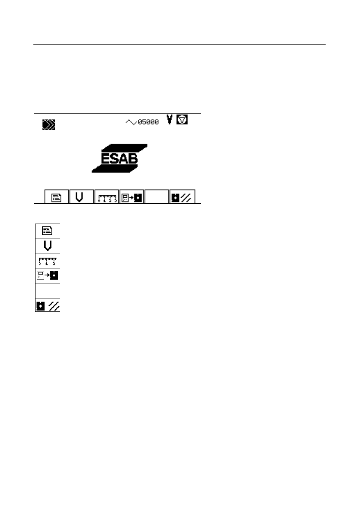
3.4 Creating a Copy of the System
The startup window provides the possibility of filing the system of the internal memory on an external
drive.
Constant editor
Speed startup
Startup help
Copy system files
Format floppy disk
41&63A0204 (vision_le_m_us_inb.doc )
Page 27
VISION LE
Startup
Startup Window Page 23
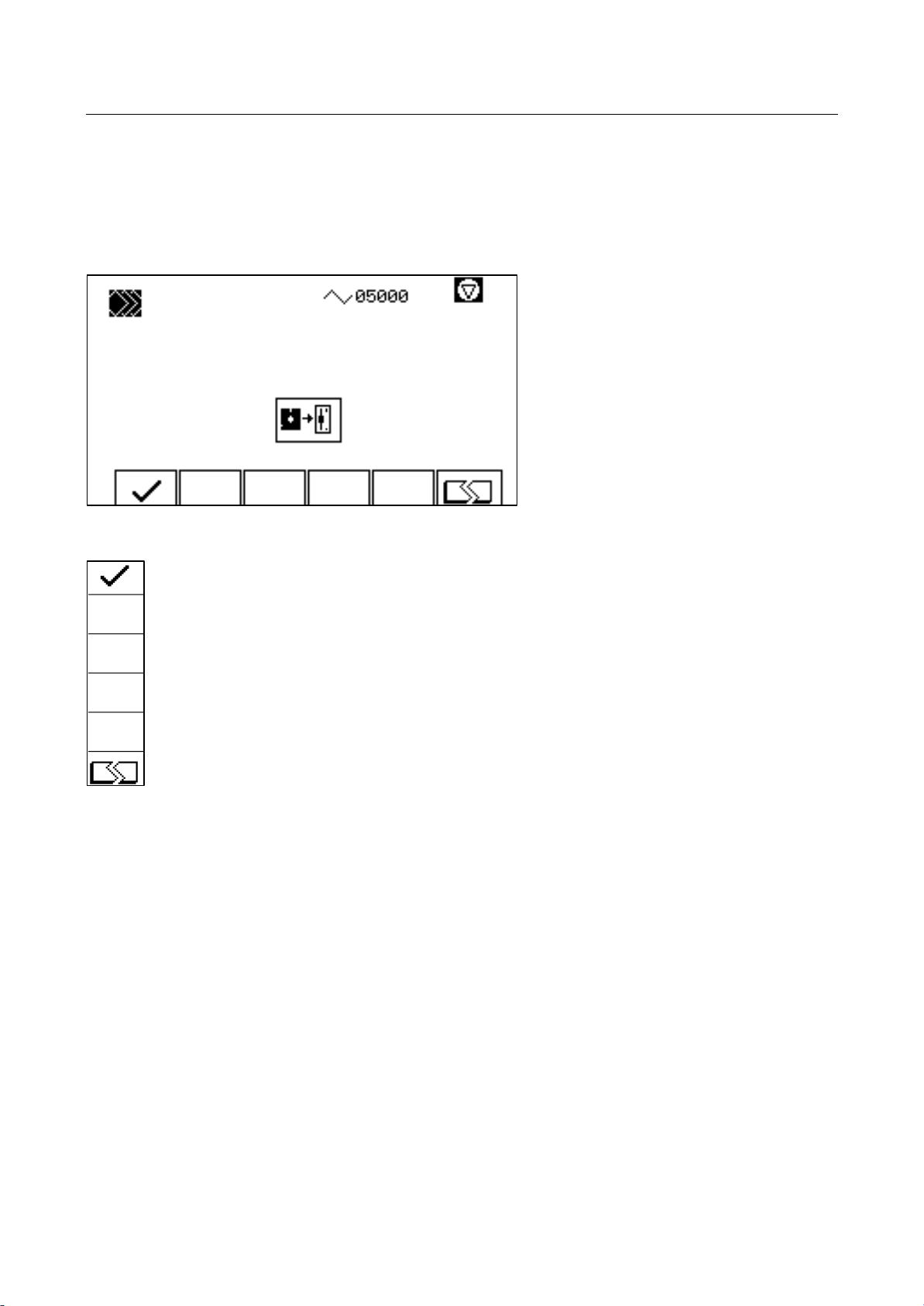
Copy System Files
Insert 1.44 MB floppy disk in drive 2.
Start copying process
Do not start copying process
Since the floppy disk is formatted during the copying process, it is not possible to cancel the process
after it has been started. If the disk is removed from the drive during copying, an error message will
be displayed and the disk will not contain usable data.
41&63A0204 (vision_le_m_us_inb.doc )
Page 28
VISION LE
Startup
Startup Window Page 24
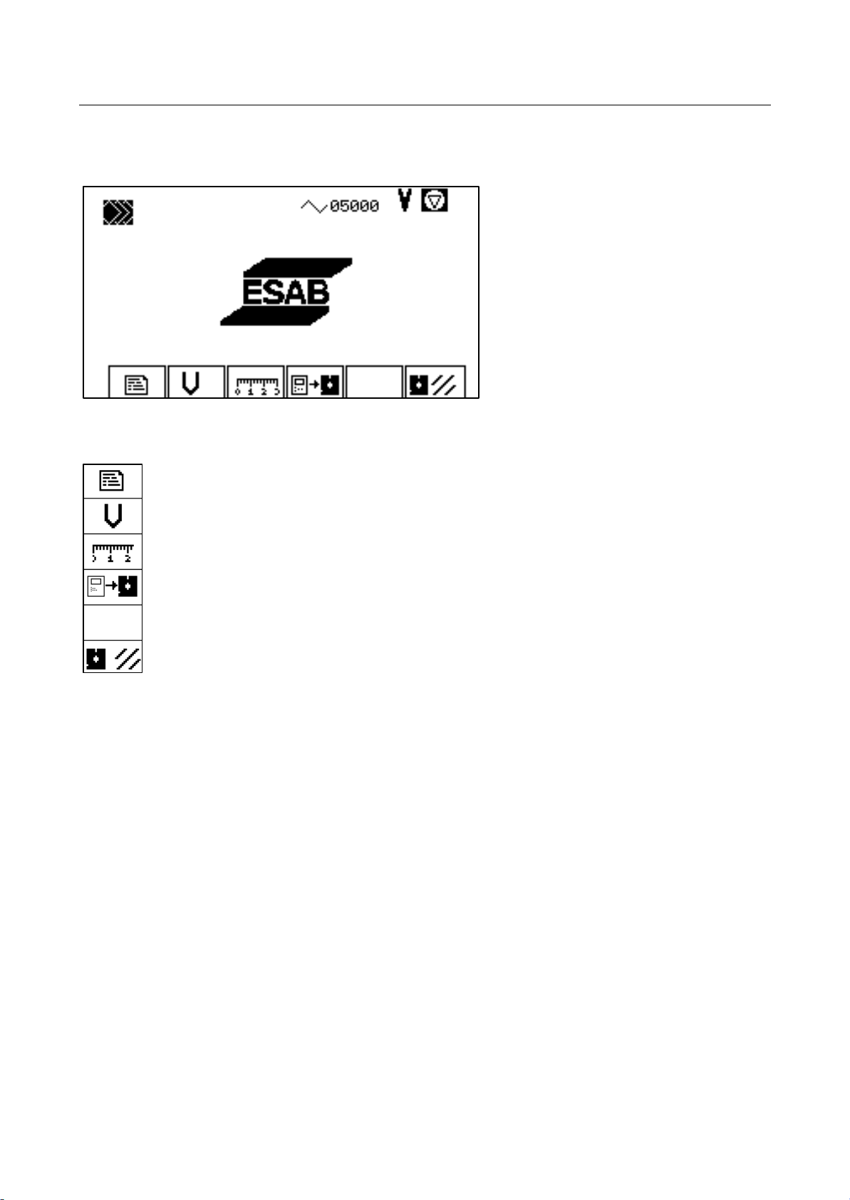
3.5 Formatting a floppy disk
Constant editor
Speed startup
Startup help
Copy system files
Format floppy disk
41&63A0204 (vision_le_m_us_inb.doc )
Page 29
VISION LE
Startup
Startup Window Page 25
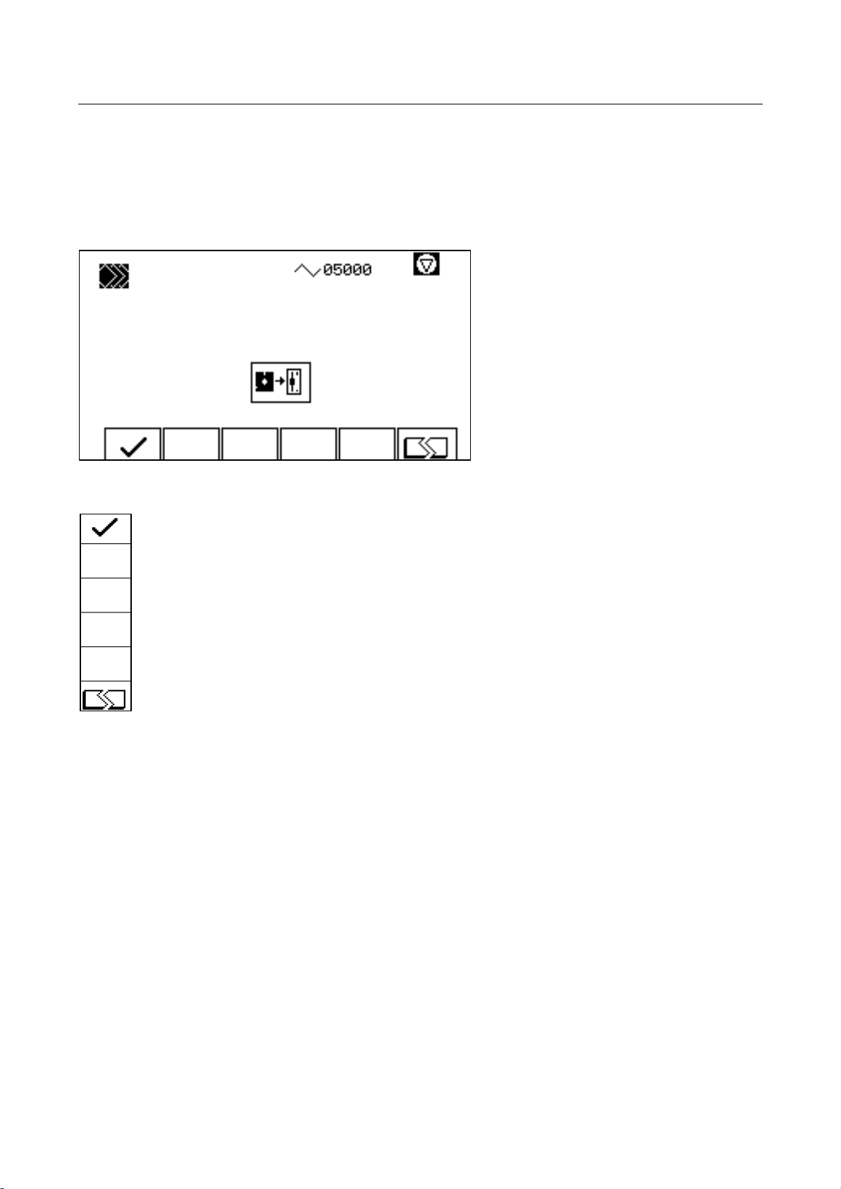
Formatting a floppy disk
Insert 1.44 MB floppy disk in drive 2.
Start formatting process
Do not start formatting process
Do not cancel the formatting process. Do not remove disk from drive during formatting process.
Otherwise the disk cannot be used.
41&63A0204 (vision_le_m_us_inb.doc )
Page 30
VISION LE
Startup
Startup Window Page 26
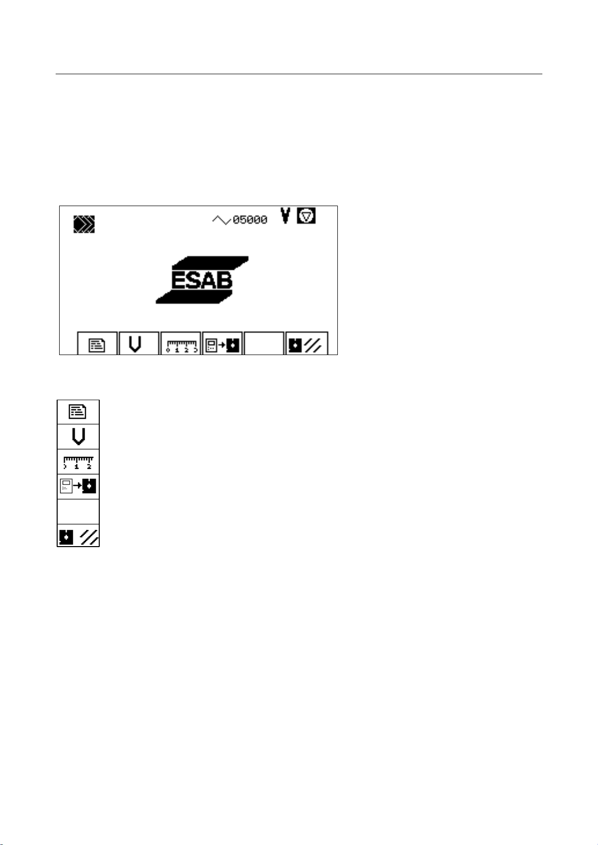
3.6 Startup Help
The control provides startup help for setting the machine zero point, for determining working ranges
and measuring tool offsets.
These values can be entered manually in the machine constants.
Constant editor
Speed startup
Startup help (page 27)
Copy system files
Format floppy disk
41&63A0204 (vision_le_m_us_inb.doc )
Page 31
VISION LE
Startup
Startup Window Page 27
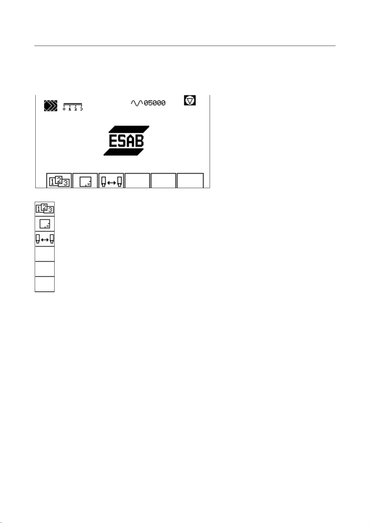
Selecting Startup Help
This help function should only be executed after speed startup.
Determine working ranges (page 28)
Setting the machine zero point (page 30)
Measuring tool offsets (page 31)
41&63A0204 (vision_le_m_us_inb.doc )
Page 32
VISION LE
Startup
Startup Window Page 28
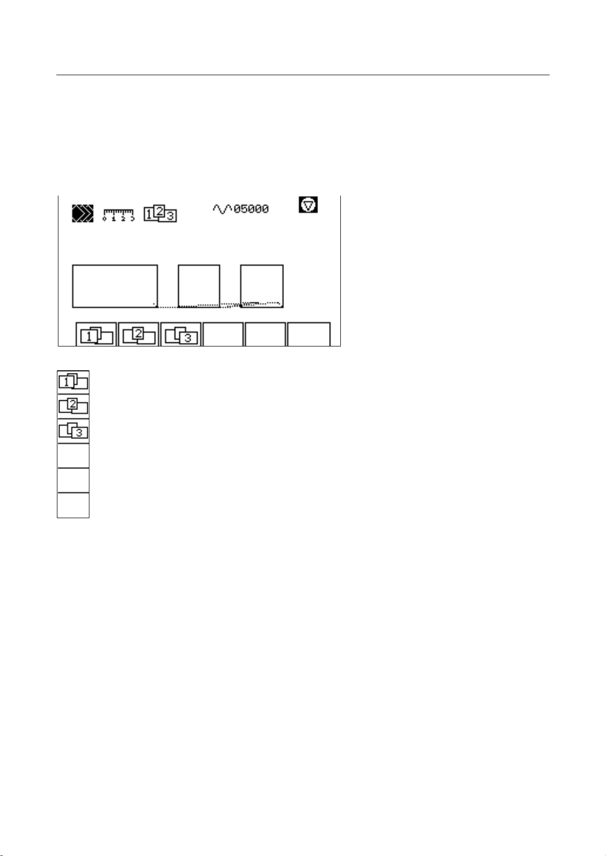
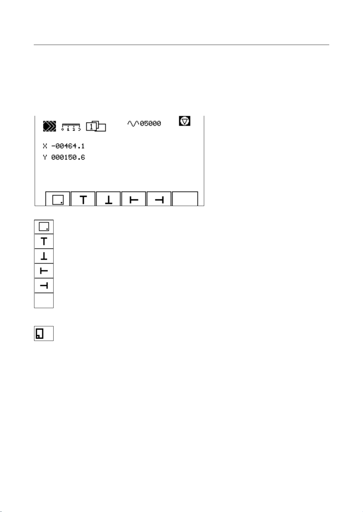
3.6.1 Determining Working Ranges
Graphical display of the currently set working ranges, visual control to check whether ranges overlap.
When applying this function for the first time, the graphics will show only one point since all values
are set to zero.
Select range 1 (page 29)
Select range 2 (optional) (page 29)
Select range 3 (optional) (page 29)
41&63A0204 (vision_le_m_us_inb.doc )
Page 33
VISION LE
Startup
Startup Window Page 29
Adjusting Ranges
Explanation of the function with the example of the first range.
Move axes as in manual control with the cursor keys. Adopted points are displayed inverse in the key
line.
Adopt fixed point of working range.
Adopt limit switch in positive longitudinal axis (X+).
Adopt limit switch in negative longitudinal axis (X-).
Adopt limit switch in positive lateral axis (Y+).
Adopt limit switch in negative lateral axis. (Y-).
Adopt range in machine constants (page 28)
41&63A0204 (vision_le_m_us_inb.doc )
Page 34
VISION LE
Startup
Startup Window Page 30
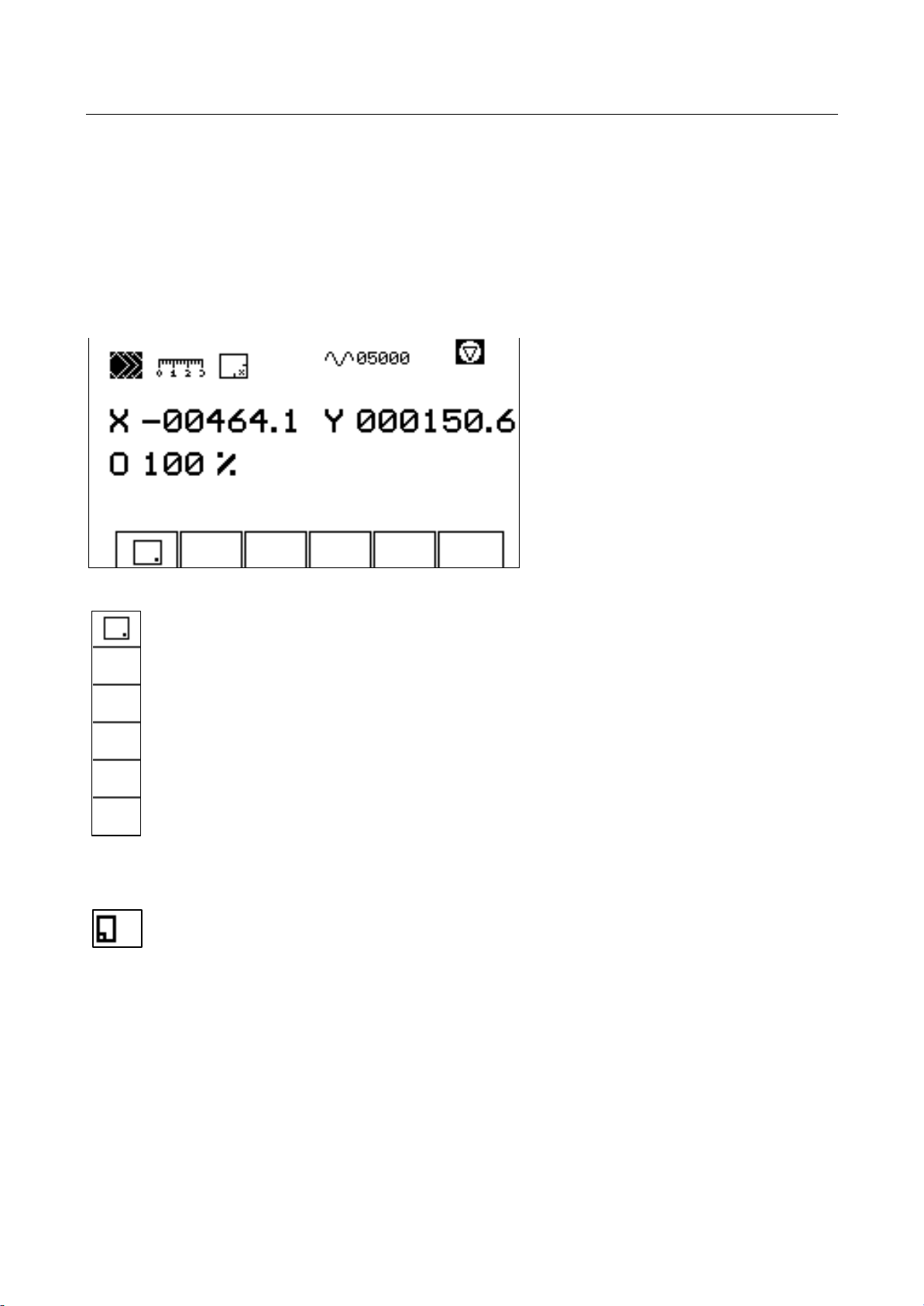
3.6.2 Setting the Machine Zero Point
Befor using this function the machine must be referenced.
As in manual control, the machine is moved with the cursor keys to the point that is to be adopted as
machine zero point. After the point has been adopted, the display of the machine corrdinates will be
corrected.
Adopt point as machine zero point.
Adopt values in machine constants.
41&63A0204 (vision_le_m_us_inb.doc )
Page 35
VISION LE
Startup
Startup Window Page 31
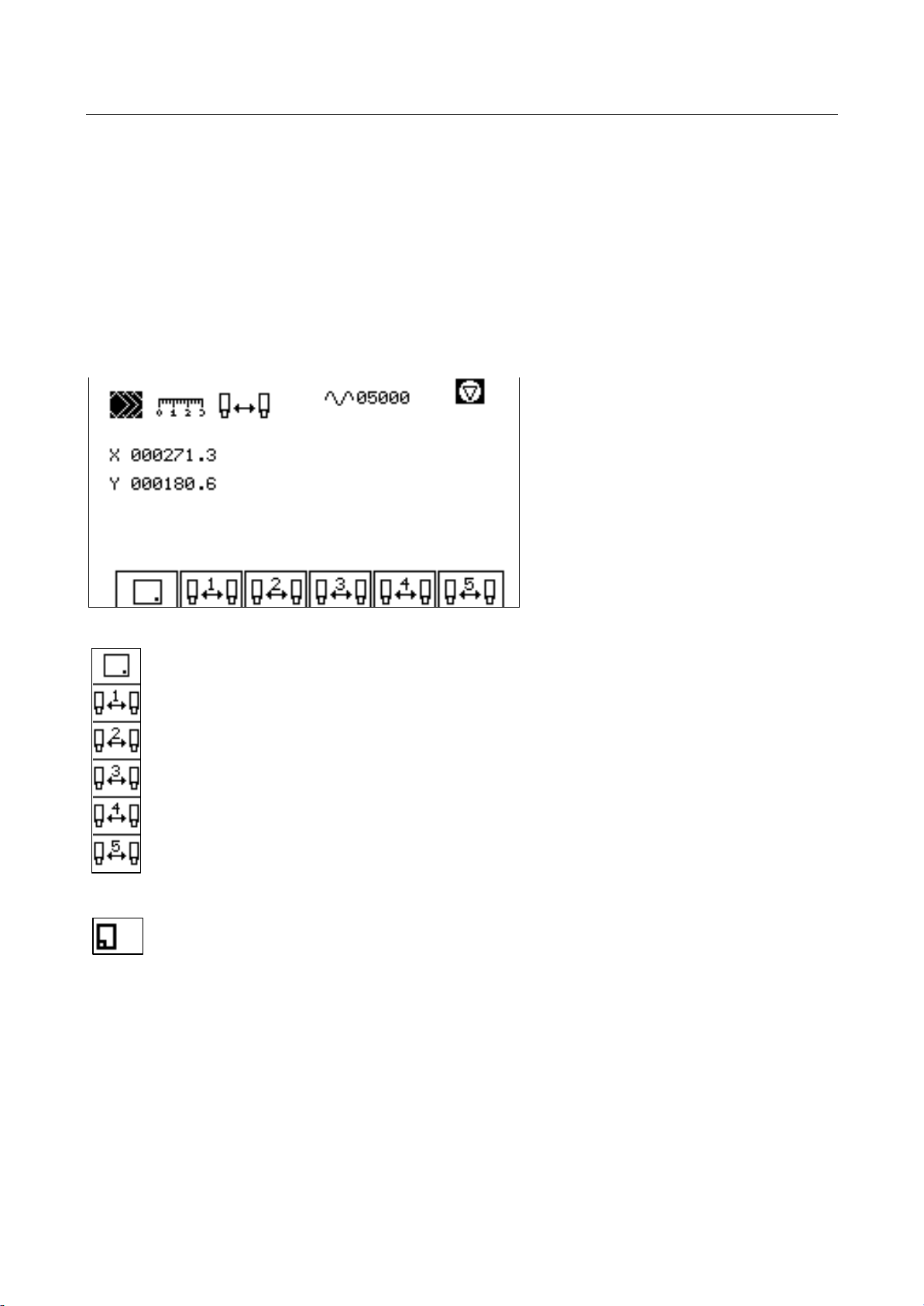
3.6.3 Measuring Tool Offsets
The offset of the individual tools to the main tool is determined with this function.
Mark a point on the plate. Position the main tool on this point. Press key "Adopt reference point".
Now, position all other tools one after the other on this point. Press the key with the corresponding
number and the distance covered is adopted as tool offset.
The keys of the adopted points are displayed inverse.
Adopt reference point
Adopt offset - tool 1
Adopt offset - tool 2
Adopt offset - tool 3
Adopt offset - tool 4
Adopt offset - tool 5
End function and adopt values in machine constants. (page 27)
41&63A0204 (vision_le_m_us_inb.doc )
Page 36

VISION LE
Startup
Service Window Page 32
4 Service Window
The service windows provide support for fault location in the case of service, as well as, a status
display of the system. The functions of the keys SHIFT/F1 through SHIFT/F5 should only be
operated by a service technician.
Attention
The functions of the key combinations SHIFT + F1 to F5 should only
be operated by a service technician. Improper operation in these
windows can lead to damage to the control system and/or the
machine.
The following functions are available:
SHIFT/F1 Deviation display (page 33)
LCD contrast setting (page 34)
SHIFT/F2 MIP signal display (page 35)
SHIFT/F3 AF / KF control (page 37 )
SHIFT/F4 Display synchronization error (page 38)
SHIFT/F5 Mini operating system (page 38 )
SHIFT/F6 Error / status display (page 41)
41&63A0204 (vision_le_m_us_inb.doc )
Page 37
VISION LE
Startup
Service Window Page 33
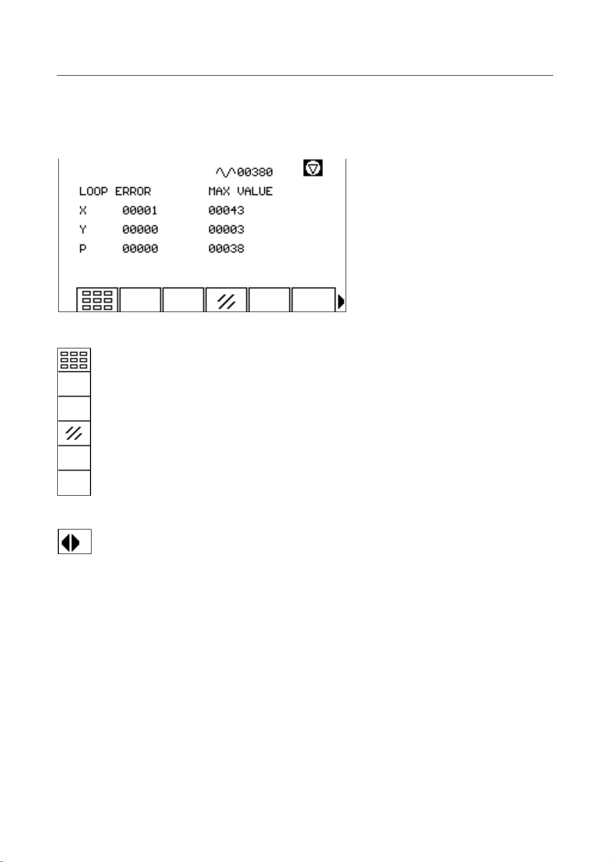
4.1 Deviation Display
Display of the current deviation in encoder impulses, as well as, the maximum deviation per axis.
Test button
Delete display of maximum value
Switch to LCD contrast setting (page 34)
41&63A0204 (vision_le_m_us_inb.doc )
Page 38
VISION LE
Startup
Service Window Page 34
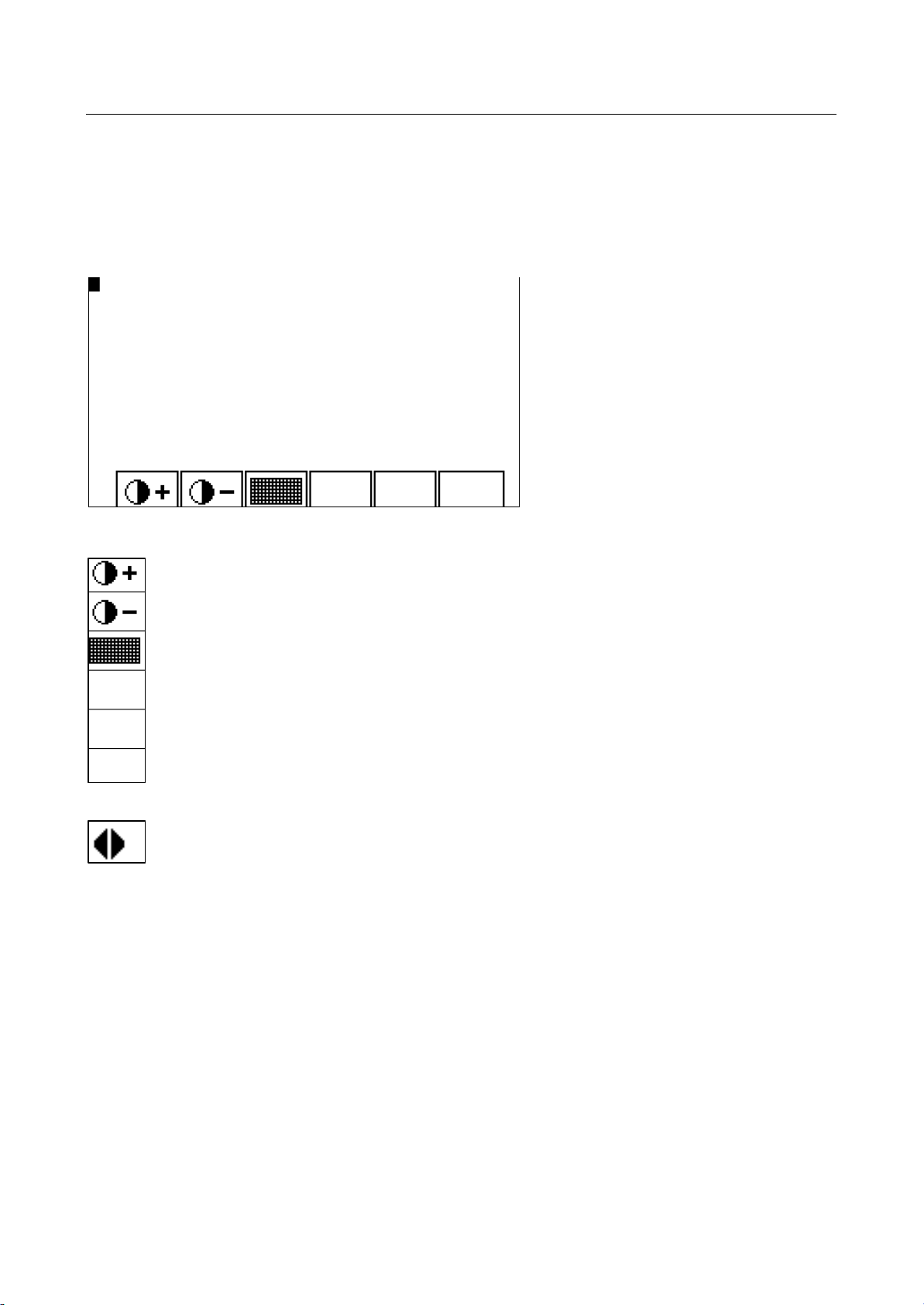
4.2 LCD Contrast Setting and Testing
The contrast of the LCD screen is set in the service window SHIFT/F1. In addition, it is possible here,
to test the screen on its operatability.
Increase LCD contrast
Reduce LCD contrast
Test screen (FONT,BLACK,WHITE)
Return to deviation display (page 33)
Note: The contrast can be changed to the extent that nothing is visible on the screen. The setting
remains even after the machine has been switched off.
41&63A0204 (vision_le_m_us_inb.doc )
Page 39
VISION LE
Startup
Service Window Page 35
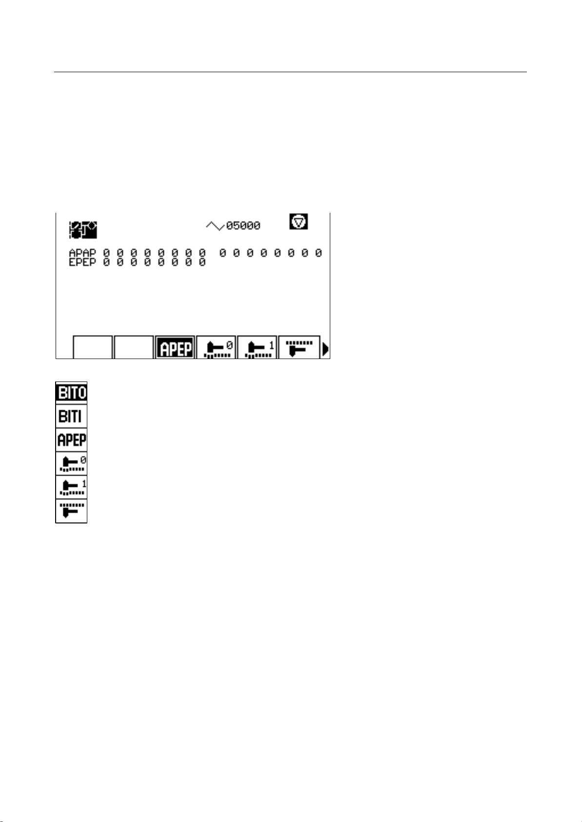
4.3 MIP Signal Display
The MIP signal display is for checking the MIP behavior. Input and output can be monitored and the
signals that correspond with the control, can be seen. It is possible to force signals (value forcing).
Positioning the cursor is done with the cursor keys.
The inverse key indicates which of the signal groups is displayed.
ASIOB output
ASIOB input
Static input and output
Force value 0 at cursor position
Force value 1 at cursor position
Cancel forced value
If the value for a signal is forced, this value is displayed inverse.
41&63A0204 (vision_le_m_us_inb.doc )
Page 40
VISION LE
Startup
Service Window Page 36
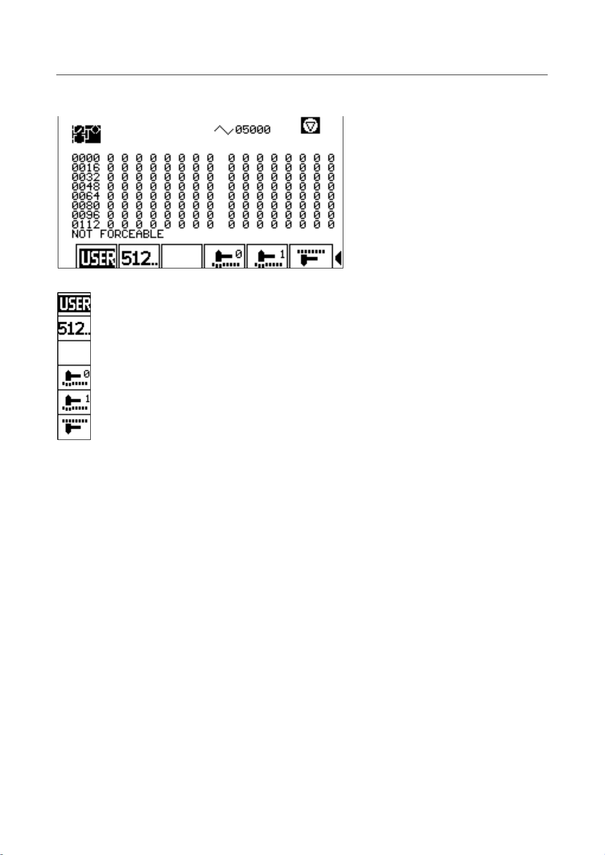
More Key of the MIP Signal Display
MIP signal
MIP signal higher than 512
Force value 0 at cursor position
Force value 1 at cursor position
Cancel forced value
41&63A0204 (vision_le_m_us_inb.doc )
Page 41
VISION LE
Startup
Service Window Page 37
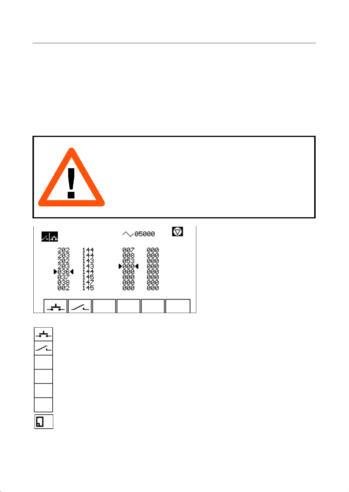
4.4 AF-KF Control
Display of the last 16 key and auxiliary functions that were sent to the MIP. The key functions (KF)
are displayed on the left side of the screen. The auxiliary functions (AF) are displayed on the right
side of the screen.
The arrow on the left side of a column indicates that the function is included in the internal list. The
arrow on the right side of the column indicates that the function has been excluded from the internal
list for the MIP.
If both arrows point away from the column, the MIP does not take anymore key or auxiliary functions.
Warning
This function is only to be used by authorized personnel, since it
requires precise knowledge of the functions. Erroneous input into
the AF-KF display can lead to erroneous behavior of the machine.
There is a high risk of injury, and damage can occur to the
machine.
Send a key function to the MIP
Send an auxiliary function to the MIP
Return to previous window
41&63A0204 (vision_le_m_us_inb.doc )
Page 42
VISION LE
Startup
Service Window Page 38
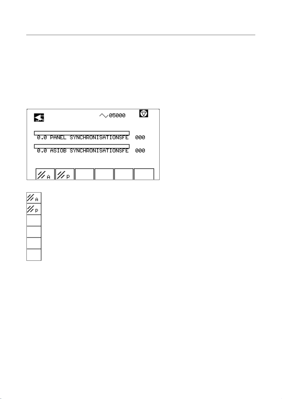
Display of Synchronization Errors
May only be activated by a service technician!
Percentage display (0-100) of ASIOB or panel synchronization errors (interferences, etc.).
Interferences with more than 30 percent are indicated by an additional error message.
Next to the bar display, there is a display of the maximum value.
Delete display of ASIOB maximum value
Delete display of panel maximum value
41&63A0204 (vision_le_m_us_inb.doc )
Page 43
VISION LE
Startup
Service Window Page 39
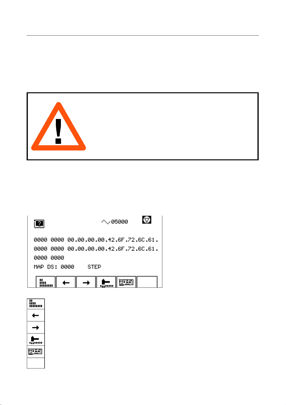
4.5 Mini Operating System
Individual data areas of the control can be monitored and changed by means of the mini operating
system.
In this case, detailed knowledge of the RAM distribution is necessary. This function is only for service
technicians.
Warning
This function is only to be used by authorized personnel, since it
requires precise knowledge of RAM organization. An erroneous
input into the mini operating system can lead to a system crash or
to erroneous behavior of the machine.
There is a high risk of injury, and damage can occur to the
machine.
In two independent lines, memory addresses can be entered. The step size for incrementing and
decrementing is always entered in bytes.
If addresses outside of the data segment are to be displayed. then the address of the data segment
has to be entered in the column "MAP DS", and the segment address of the memory in the first
column of the display line. Addresses are to be taken from the ANC.MAP file.
For a display within the data segment these two values have to be kept on ZERO.
Switch to word, long or byte display
Decrement address by step size
Increment address by step size
Set value
Switch to absolute addresses (hardware)
41&63A0204 (vision_le_m_us_inb.doc )
Page 44

VISION LE
Startup
Service Window Page 40
Certain memory addresses can be accessed directly via an index. For this, enter "F000" in the first
column (segment address). In the second column (offset) enter the index of the desired memory
address according to the following list.
The "MAP DS" value is not relevant for this display. Switching to absolute addresses does not have
any effect, either.
Ind Description
Deviation in encoder units (32 bit)
1 X-axis
2 Y-axis
4 P-axis
Voltage of deviation share 7FFF = 10 volt (16 bit)
5 X-axis
6 Y-axis
8 P-axis
Voltage of speed pick-up Vmax axis (MC) = 8 volt (16 bit)
9 X-axis
A Y-axis
C P-axis
Total voltage output of deviation share and speed pick-up (16 bit)
D X-axis
E Y-axis
10 P-axis
Actual values in encoder units (32 bit)
1D X-axis
1E Y-axis
20 P-axis
Tool path feed rate in [µ] or [mil] (32 bit)
21 X-axis
22 Y-axis
24 P-axis
41&63A0204 (vision_le_m_us_inb.doc )
Page 45
VISION LE
Startup
Service Window Page 41
4.6 Error - Status Display
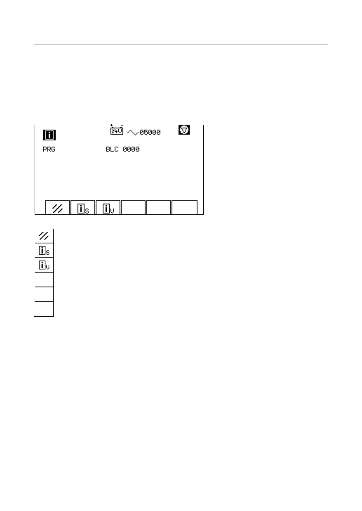
Errors that have occurred are displayed, if possible, with additional information.
The name of the current or last processed program is indicated with PRG. BLC indicates the current
block number of the processed program.
Delete error
Switch to status display (page 42)
Switch to version number display (page 45)
41&63A0204 (vision_le_m_us_inb.doc )
Page 46
VISION LE
Startup
Service Window Page 42
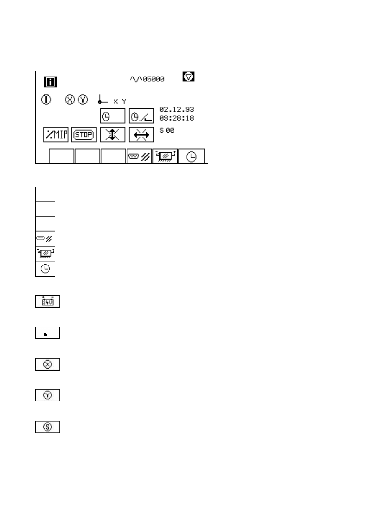
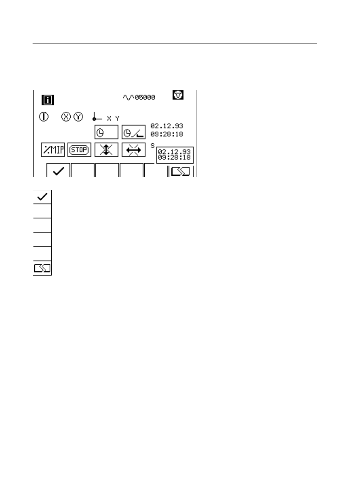
Status Display
Reset I/O ports
Reset battery ram
Time setting (page 44)
Turn-on voltage.
This symbol is displayed in the top right corner of the screen when the turn-on voltage
is switched on.
Reference.
The letters to the right of this symbol indicate from which of the axis the reference was
adopted.
Controller release X.
Indicator for controller release in the X-axis. If this symbol is not displayed, the
machine cannot be operated along the X-axis.
Controller release Y.
Indicator for controller release in the Y-axis. If this symbol is not displayed, the
machine cannot be operated along the Y-axis.
SPC release.
Indicator for SPC release. If this symbol is not displayed, no auxiliary or key functions
are sent to the MIP.
41&63A0204 (vision_le_m_us_inb.doc )
Page 47

VISION LE
Indicates that the feed release is missing. The signal is the inverse representation of
Startup
Service Window Page 43
Feed release.
Indicator for feed release. The feed release is set by the MIP. It allows machine
movements.
Feed interlock.
the feed release. Axis movements are prevented.
41&63A0204 (vision_le_m_us_inb.doc )
Page 48
VISION LE
Startup
Service Window Page 44
Time Setting
Setting the time. The adjustment is done with the cursor keys.
Adopt time
No adoption
41&63A0204 (vision_le_m_us_inb.doc )
Page 49
VISION LE
Startup
Service Window Page 45
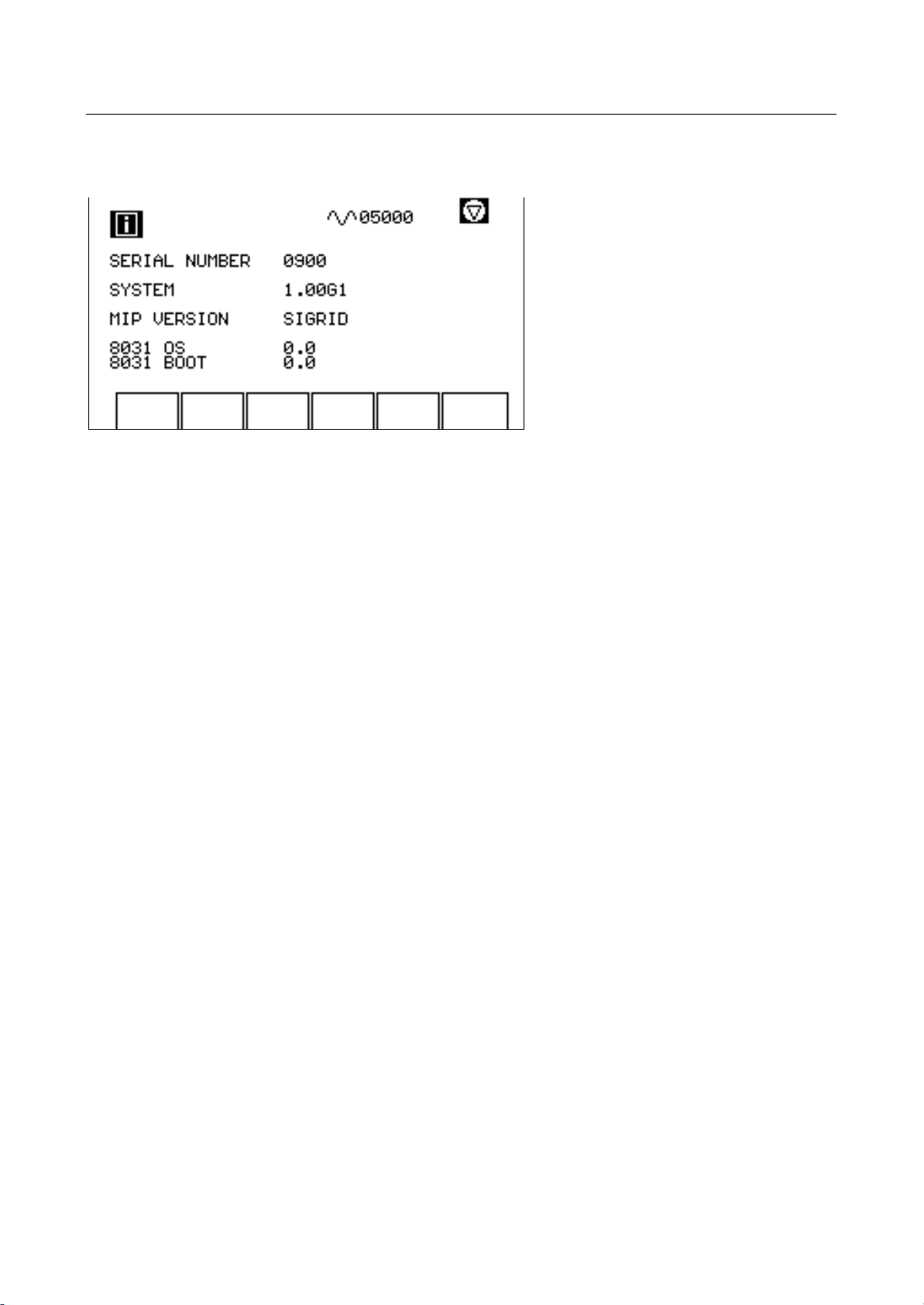
Display of Version Number
Serial number: Control number
System: Version number of the basic system (ANC.EXE)
MIP version: Version number of the MIP program (MIP41.MIP)
8031 OS: Operating system number of the sub system (NOS8031.BIN)
8031 Boot: Version number of the boot loader of the sub system (BOOT8031.HEX)
41&63A0204 (vision_le_m_us_inb.doc )
Page 50

VISION LE-L
Startup - PRELIMINARY VERSION
System of the VISION LE-L Page 46
5 System of the VISION LE
The system of the VISION LE is located on a flash disk.
5.1 Files of the internal memory
The following is a listing of the files that constitute the system of the VISION LE.
Name Ext Type Description
ATASSYS B Boot loader for VISION LE-L
ANC EXE B System file VISION LE-L
BOOT8031 HEX B Boot loader for 8031
BOS8031 BIN B Subsystem 8031 (ABIMBO)
NOS8031 BIN B Subsystem 8031 (ATHC2)
LCD GOM B System user interface
LCDMIP GOM B Process user interface
MIP41 MIP B Machine interface program
ALL SHP B Standard shape library
ANCDEF KON A/B Add-ons configuration
DEV KON A Device constants
SYS KON A System constants
MAS KON A Machine constants
MIP KON A MIP constants
MAKROS DEF A Macro key definitions
DEF TEC A Technology definitions
PARAM CUT A Technology data
STAT01 KON A Constants station 1
STAT02 KON A Constants station 2
STAT03 KON A Constants station 3
STAT04 KON A Constants station 4
STAT05 KON A Constants station 5
STAT06 KON A Constants station 6
STAT13 KON A Constants central station 1
STAT14 KON A Constants central station 2
STAT15 KON A Constants central station 3
EIA_ESSI DEF B/A EIA definition file
ALL BUG A Character generator library
In the category "Type", B indicates a binary data record and A an ASCII record that can be read with
any editor.
Only for those stations that are actually available on the machine, the corresponding constants are
located on the system flash drive. This is also true for add-ons that need a data record.
The file ANCDEF.KON determines the expansion of the control with add-ons. This data record
should not be altered, it could otherwise endanger the functioning of the control.
41&63A0204 (vision_le_m_us_inb.doc )
Page 51

VISION LE-L
Startup - PRELIMINARY VERSION
System of the VISION LE-L Page 47
The remaining data files with the extension "KON", as well as the files MACROS.DEF, DEF.TEC and
PARAM.CUT contain constants and settings that are defined during the startup of the machine. They
cannot be altered during operation. Exceptions are marked and, if necessary, they can be adapted
by the user of the machine.
EIAMHF.DEF is an additional EIA definition file. Customer-specific adaptations of the M-function can
be done in this file. Adaptations take place as follows:
“M function“=“ESSI function“.
For example: M0=42
converts the EIA function M0 into the ESSI function 42.
41&63A0204 (vision_le_m_us_inb.doc )
Page 52

VISION LE
Startup
System of the VISION LE Page 48
5.2 System Constants
List of system constants
01 DECIMAL SPEED
02 NOT USED
03 TYPE KERF CALCULATION
04 ENCODER SIMULATION
05 MIP SIMULATION
06 CIRCLE MODE
07 DECIMAL POINT N/Y 0/1
08 MM OR INCH 0/1
09 EIA KEYS
10 PROCESS HANDLING
11 CUTTING PACKAGE RESET
12 NOT USED
13 NOT USED
14 DO NOT MOVE TO GRID POSITION
15 NOT USED
16 NOT USED
17 NOT USED
18 NOT USED
19 NOT USED
20 NOT USED
21 NOT USED
22 NOT USED
23 NOT USED
24 NOT USED
25 NOT USED
26 NOT USED
27 MIXED ESSI-EIA
28 STANDARD SHAPE IN EIA
29 BASETEXT
30 LUBRICATION
31 NOT USED
32 NOT USED
33 NOT USED
34 EIA PROGRAMMING ACCURACY MM-COORDINATES
35 EIA PROGRAMMING ACCURACY INCH-COORDINATES
36 NOT USED
37 NOT USED
38 NOT USED
39 NOT USED
40 NOT USED
41 NOT USED
42 REFERENCE MODE
43 NOT USED
44 NOT USED
45 NOT USED
46 NOT USED
47 NOT USED
48 NOT USED
41&63A0204 (vision_le_m_us_inb.doc )
Page 53

VISION LE
Startup
System of the VISION LE Page 49
49 ESAB/LTEC LOGO
50 NOT USED
51 ERROR WAITING TIME
52 NOT USED
53 NOT USED
54 CUSTOMER
55 BUS VERSION
56 NOT USED
57 RESERVED (ES)
58 RESERVED (P)
59 RESERVED (A)
60 RESERVED (WD)
61 RESERVED (SC)
62 RESERVED (I)
63 RESERVED (DIO)
78 START WITH PART
79 MANUAL INPUT RELATIVE
105 INVERSE CUTSENSE SIGNAL
106 EXT. TRACER CONNECTED
107 US LOGIC
108 TYPE OF HARDWARE
109 ERROR SUPPRESSION
110 KEYBOARD
41&63A0204 (vision_le_m_us_inb.doc )
Page 54

VISION LE
Startup
System of the VISION LE Page 50
Description of the system constants
1 Decimal speed
The value for speed is displayed in either mm/min or inches/min. The decimal point of the speed
display can be shifted.
0 No decimal point.
1 Decimal place before the last digit; indicates 1/10 of a unit.
3 Decimal place before the second from last digit; the last digit indicates 1/100 of a unit
and the second from last digit indicates 1/10 of a unit.
3 Type of kerf calculation
The procedure of the kerf calculation can be controlled with this constant. The following input values
can be entered in form of a binary sum in order to combine chara cteristics.
00001 Activates collision checking.
00010 Small segments of arcs with a section height smaller than 1/10 mm are interpreted as
a line. This measure prevents collision of the offset contour with the programmed
segment for small arcs.
00100 Forces a linear movement from the last point without offset activated to the first point
with activated offset. A jump in the form of a line with half of the offset value is not
generated.
01000 Movement proceeds from the last offset point of a contour directly to the first
subsequent point without offset, if the offset mode is not activated. Here again, no line
with half of the offset length is generated from the corrected point to the same point
uncorrected.
10000 Kerf on the fly. Permits changing the offset by rotary knob during the program
movement. The offset can be adjusted by +/- 50%. It must be kept in mind that sets
which are already precalculated are not affected by the changed offset. After an AF
30/29 the changed offset is visible immediately.
4 Encoder simulation
For testing purposes, control functions can be simulated without encoders. The setpoint of a contour
is taken as actual value. Position control as well as reference point movement are of no relevance.
Note: When axis simulation is activated, individual functions are no longer available.
41&63A0204 (vision_le_m_us_inb.doc )
Page 55

VISION LE
Startup
System of the VISION LE Page 51
5 MIP simulation
In order to override certain actions of the existing MIP program, the following settings can be made.
The following input values can be entered in the form of a binary sum in order to combine
characteri stics.
0001 MIP is not able to cancel the feed release.
0010 Error messages generated by the MIP are not displayed.
0100 Simulation of a positive response after a download of station constants. Missing
stations are treated as if they were present.
1000 Display of all ATHC messages for existing stations.
6 Circle mode
The interpretation of circle center point coordinates for EIA programs is set with this constant.
0 Standard interpretation. Circle center point coordinates are programmed absolute or
incremental to the starting point in dependence of the path conditions.
1 Circle center points coordinates are always incremental to the starting point
independent of path conditions.
2 Missing circle center point coordinates are supplemented, assuming that the arc is
always within a quadrant.
3 Missing circle-center coordinates are added, using the most recently used circle-
center coordinates.
7 Decimal point
Programming decimal points in EIA format.
0 No decimal point in EIA format is expected. Coordinate values are interpreted
according to machine constant 49 as 1/10mm, 1/100mm or 1/1000 inch.
1 A decimal point in EIA format is expected. For a missing point, all values are
interpreted in millimeter or inch units.
8 MM or INCH
The setting for MM, MM/MIN or I, IPM is set by the manufacturer of the machine. The setting
depends on the machine. Modification of these constants may only be done by the manufacturer of
the machine.
0 Text displays in MM or MM/MIN.
1 Text displays in I or IPM.
41&63A0204 (vision_le_m_us_inb.doc )
Page 56

VISION LE
Startup
System of the VISION LE Page 52
09 EIA keys
If EIA programming is mainly used, the assignment of the +/- keys can be redefined:
1 key without shift is the decimal point
key with shift is the plus character
10 Process handling
Whenever the control is switched on, the process used last is activated and the corresponding
stations are selected.
001 Stations and process are not activated automatically at system start.
010 No option level available after manual process selection - control level is activated
immediately (American version only).
100 The process selection level can be accessed via the PAGE key (American version
only).
11 Cutting package reset
If only the data of the basic cutting package (no additional SDP cutting data files) with the values
specified therein (no values specified in the battery RAM) are to be used, set this constant to “1“
(yes). When the system is started again the basic cutting package is loaded. Set this constant back
to "0“ (no) afterwards.
Notice: Deleting the battery RAM results in a reloading of the basic cutting package with its basic
setting. Other data however are lost.
14 Do not move to grid position
The option "Accept program zero point (grid)" sets the machine so that all programs begin at a fixed
absolute machine point. If this constant is set, the program zero point is the position at which the
program is started.
This constant is in effect only when the constant is act ivated.
0 Manual definition of the program zero point (optional feature) is deactivated in the
basic setting.
1 Manual definition of the program zero point (optional feature) is activated in the basic
setting.
27 Mixed ESSI-EIA
Programs written in ESSI and EIA format are used.
41&63A0204 (vision_le_m_us_inb.doc )
Page 57

VISION LE
Startup
System of the VISION LE Page 53
0 No mixed programming.
1 Mixed programming.
28 Representation of standard shapes in ESSI/EIA
If the control system is equipped with the optional feature "EIA format“, this constant serves to define
which program format (ESSI or EIA) the control system uses to generate main programs from
standard shapes or in the "Teach-Trace mode."
0 Program generation in ESSI format.
1 Program generation in EIA format.
29 Basetext
Language setting
0 The language used in the system is the non-native language stored in FREMDTXT or
FREMDMIP.GOM.
1 The language used in the system is the basic text stored in LCD or LCDMIP.GOM.
After changing this constant you must restart the system for the new language to become effective
(after saving the system constants)
30 Lubrication
Specification of the movement path in meters after which the MIP receives a message for automatic
lubrication of the axes.
34 EIA programming accuracy MM-coordinates
35 EIA programming accuracy INCH-coordinates
These constants determine the precision of a programming unit. If the machine is set to millimeters,
the program accuracy is taken from constant 34; for inches, from constant 35 (also see constant SYS
8).
0 Do not enter decimal points in the EIA format. Coordinate values are programmed in
1/1 [mm] or 1/1 [inch}.
1 Do not enter decimal points in the EIA format. Coordinate values are programmed in
1/10 [mm] or 1/10 [inch].
2 Do not enter decimal points in the EIA format. Coordinate values are programmed in
1/100 [mm] or 1/100 [inch].
3 Do not enter decimal points in the EIA format. Coordinate values are programmed in
1/1000 [mm] or 1/1000 [inch].
8 Decimal points are expected in the EIA format. Coordinate values are programmed in
[mm] or [inches] (X1005 means 1005 mm or inches).
9 Decimal points are expected in the EIA format. Coordinate values are programmed
with one decimal place in [mm] or [inches]. (X100.5 means 100.5 mm or inches).
41&63A0204 (vision_le_m_us_inb.doc )
Page 58
VISION LE
Startup
System of the VISION LE Page 54
10 Decimal points are expected in the EIA format. Coordinate values are programmed
with two decimal places in [mm] or [inches] (X10.05 means 10.05 mm or inches).
11 Decimal points are expected in the EIA format. Coordinate values are programmed
with three decimal places in [mm] or [inches] (X0.005 means 0.005 mm or inch).
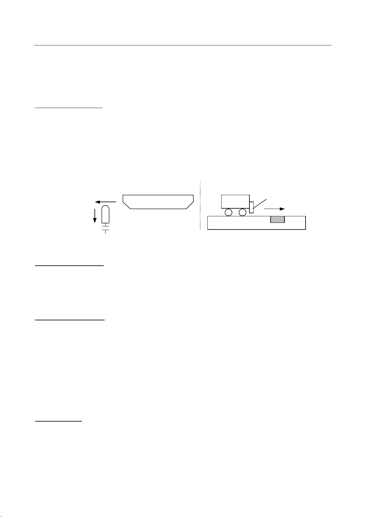
42 Reference mode
Specifies the manner in which the control system automatically references the axes.
0 Standard. The reference points are recognized on the basis of a cam (mechanical
switch). The reference point is the contact point of the switch.
1 Alternative. The reference points are se t by recognizing holes (inductive sensor). The
reference point is the center of the recognized hole.
Value 0 Value 1
Sensor
Hole
Contact
Axis
Axis
49 ESAB/LTEC logo
0 The startup message of the control is "ESAB".
1 See SYS54
51 Error waiting time
If an error occurs, it is displayed immediately by the control system. After it is acknowledged by the
operator, the error is deleted. If the error occurs again immediately after the attempt at deletion (for
example because of responses from the hard ware), the repeated message is suppressed. The error
continues to be displayed in the error window.
This constant defines the waiting time (in units of 16 ms) during which the error message is
suppressed.
Values 10 to 90 are admissible.
54 Customer
0 The startup messa ge of the control is "NCE290" if SYS49 = 1.
1 The startup message of the control is "VISION LE" if SYS49 = 1.
41&63A0204 (vision_le_m_us_inb.doc )
Page 59
VISION LE
Startup
System of the VISION LE Page 55
55 BUS version
Information on the hardware connected to ASIOB.
0 ATHC-2 card (intelligent station) at the ASIOB.
1 ABIMBO connected to the ASIOB (American version).
2 No ASIOB
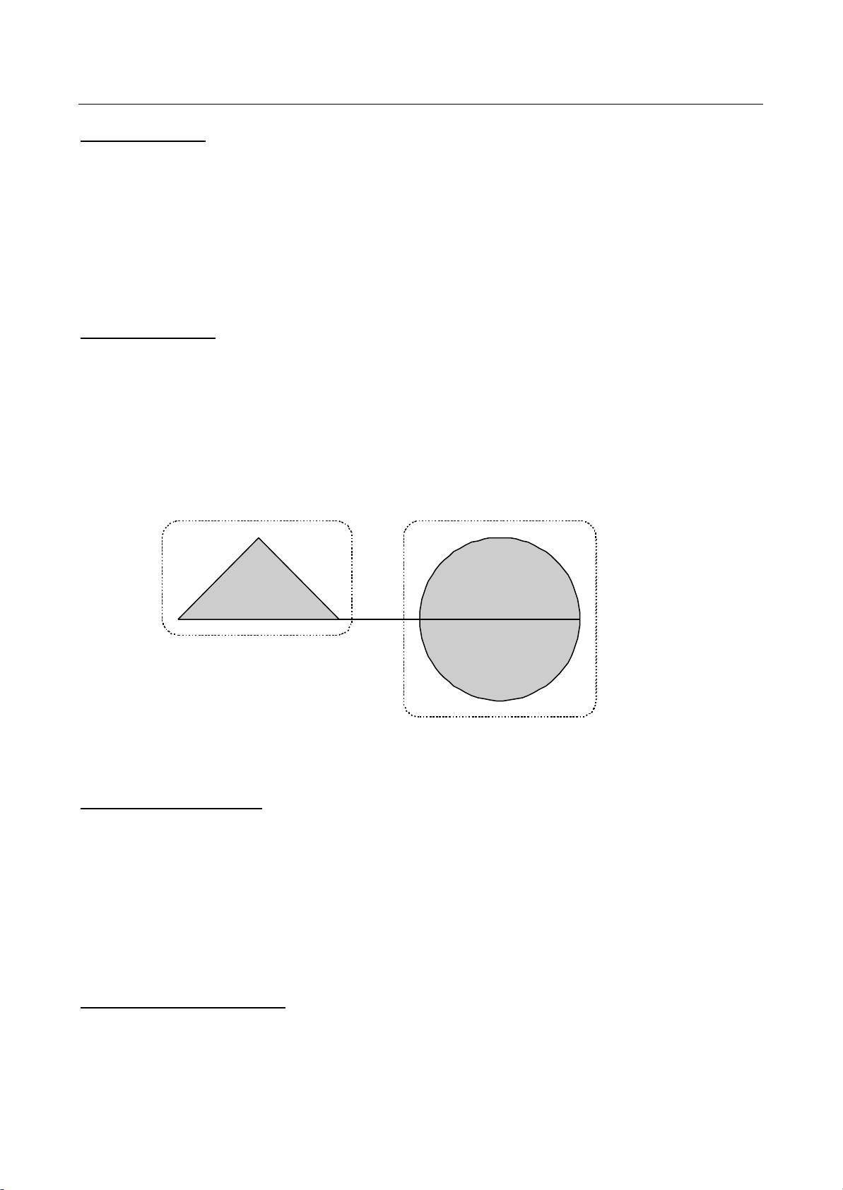
78 Start with part
On the automation menu, analogous to "Start with block number," "Start with part" is possible. A part
in the parts program begins with an AF+n (or M0 for EIA), where n is the part number. The end of a
part is identified by "EOS" (End Of Sheet).
0 Input of "Start with part" not possible.
1 Input of "Start with part" possible.
Sample program:
0
6
++++50+
7
++150
EOS
0
6
++100
+50-50
-50-50
7
EOS
Part 2 Part 1
The grafic display is not supported in the editor.
79 Manual input relative
The machine can also be positioned by means of direct entry of coordinates. This constant is used to
set whether the input is interpreted absolutely or relative to the cu rrent position.
0 Relative.
1 Absolute.
105 Inverse onpattern signal
Definition of the signal "On pattern" of an optical copying attachment.
41&63A0204 (vision_le_m_us_inb.doc )
Page 60

VISION LE
Startup
System of the VISION LE Page 56
0 Marker 882 is 1 at "On pattern"
1 Marker 882 is 0 at "On pattern"
106 External tracer connected
Type of optical copying attachment, that is connected to the control:
0 AK5 is connected
1 HL70 / HL90 is connected
107 US logic
The output of the 24 volt power and thus also the run time of the MIP can be defined differently:
0 24 volt power is always switched on. No signal output by the control.
1 24 volt power is switched on by means of an external signal, No signal output by the
control.
2 24 volt power is switched on/off by Start/Stop. Signal output via APAP16. (Relais X12
7/-X12.8)
3 24 volt power is switched on/off by Start/Stop. Signal output via APAP. External signal
defines release of the 24 volt power.( X8.9)
4 See 3. In addition the message 163: „Emergency stop chain interrupted“ is issued, if
the external signal (Usok, X8.9) switches from 1 to 0.
5 24 volt power is switched on/off by Start/Stop. Signal output via APAP16. (Relay X12
7/-X12.8): Emergency braking behaviour with input Usok, (X8.9) as emergency stop
input (like ANC41).
108 Type of hardware
Hardware availlable on the control
0 No hardware for VISION LE
1 no joystick connected, manual movement by means of the cursor keys.
2 Joystick connected, no manual movement by means of the cursor keys.
109 Error suppression
Control of the display of cable faults and frequency errors co nsidering the machine constant
MAS51.
0 Suppression of cable fault is possible, no suppression of
frequency error.
1 Cable fault and frequency error are suppressed as long as
the communication marker is M994=1. The machine
constant is ignored. That way the MIP can suppress the
error display during the plasma ignition.
2 Cable fault and frequency error are always suppressed.
41&63A0204 (vision_le_m_us_inb.doc )
Page 61

VISION LE
Startup
System of the VISION LE Page 57
110 Keyboard
For testing purposes a PS2 keyboard can be connected to the control.
Caution:
Exclusively for service operation, the connected keyboard leads to malfunctions.
41&63A0204 (vision_le_m_us_inb.doc )
Page 62

VISION LE
Startup
System of the VISION LE Page 58
5.3 Machine constants (MAS.KON)
List of machine constants.
01 X EXISTENT 1/0
02 Y EXISTENT 1/0
03 NOT USED
04 P EXISTENT 1/0
05 X ENCODER ROTATION DIRECTION 0/1
06 Y ENCODER ROTATION DIRECTION 0/1
07 NOT USED
08 P ENCODER ROTATION DIRECTION 0/1
09 X LA [1/SEC]
10 Y LA [1/SEC]
11 NOT USED
12 P LA [1/SEC]
13 X SPEED/8V [MM/MIN]
14 Y SPEED/8V [MM/MIN]
15 NOT USED
16 P SPEED/8V [MM/MIN]
17 X PULSES/1000 MM
18 Y PULSES/1000 MM
19 NOT USED
20 P PULSES/1000 MM
21 REFERENCE X [1/1000MM]
22 REFERENCE Y [1/1000MM]
23 HOME POSITION 1 X [MM]
24 HOME POSITION 1 Y [MM]
25 SOFT LIMIT 1 +X [MM]
26 SOFT LIMIT 1 -X [MM]
27 SOFT LIMIT 1 +Y [MM]
28 SOFT LIMIT 1 -Y [MM]
29 NOT USED
30 NOT USED
31 NOT USED
32 NOT USED
33 NOT USED
34 NOT USED
35 NOT USED
36 NOT USED
37 NOT USED
38 NOT USED
39 NOT USED
40 NOT USED
41 MAX SPEED [MM/MIN]
42 ACCELERATION TIME [MS]
43 MANUAL FAST MOTION [MM/MIN)
44 MANUAL FEED [MM/MIN]
45 TEACH TRACE KV [1/SEC]
46 TEACH QUER KV [1/10SEC]
47 PORTAL DEVIATION [1/10MM]
41&63A0204 (vision_le_m_us_inb.doc )
Page 63

VISION LE
Startup
System of the VISION LE Page 59
48 SMOOTH FACTOR
49 MACHINE UNIT 0/1/2/3
50 NOT USED
51 SUPP CABLE ERROR 0/1
52 REFERENCE Y/N 1/0
53 LOOP MODE
54 TIPP/LATCH
55 AC DRIVES
56 NOT USED
57 NOT USED
58 NOT USED
59 NOT USED
60 NOT USED
61 NOT USED
62 NOT USED
63 NOT USED
64 AUTOREF X
65 AUTOREF Y
66 NOT USED
67 NOT USED
68 TOOL OFFSET 1 X[1/1000MM]
69 TOOL OFFSET 1 Y[1/1000MM]
70 TOOL OFFSET 2 X[1/1000MM]
71 TOOL OFFSET 2 Y[1/1000MM]
72 TOOL OFFSET 3 X[1/1000MM]
73 TOOL OFFSET 3 Y[1/1000MM]
74 TOOL OFFSET 4 X[1/1000MM]
75 TOOL OFFSET 4 Y[1/1000MM]
76 TOOL OFFSET 5 X[1/1000MM]
77 TOOL OFFSET 5 Y[1/1000MM]
78 2. ACCELERATION TIME [MS]
79 DEVIATION X1/X2 [1/1000MM]
155 EMERG. DECCEL [MS]
156 X BACKLASH COMP
157 Y BACKLASH COMP
159 P BACKLASH COMP
160 TIME ON EDGE
161 MIN. ANGLE STOP ON EDGE [DEGREE]
169 LASER POINTER OFFSET X [1/1000MM
186 LIMIT SEARCH SPEED TT
232 X NEGATE OUTPUT VOLT
233 Y NEGATE OUTPUT VOLT
41&63A0204 (vision_le_m_us_inb.doc )
Page 64

VISION LE
Startup
System of the VISION LE Page 60
Description of the machine constants
1,2 Axis definitions
Enter whether X-axis and Y-axis exist. Usually both constants are 1.
0 Axis not available
1 Axis available
4 Portal axis
Machines with a portal can be moved along the X-axis via two separate drives. These drives,
however, have to be synchronized. Such portal control is an additional function to the VISION LE.
When this function is installed, this constant can be set to 1. The following axis constants have to be
entered separately (from the X-axis) also for the P-axis.
5,6,8 Rotation direction
After mounting and cabling, the encoders on the machine will not always produce positive actual
values with positive axis direction. This matter is checked during automatic speed startup and, if
necessary, a 1 is entered automatically during measurement in order to correct the rotation direction
of the encoder.
In case of a wrong entry in this constant, the position control cannot work. Deviation errors can also
occur in case of axis standstill.
Caution:
Do not enter the value manually. With an inco rrect input for these constants the closed-loop position
control may not be available
9,10,12 Amplifying factor (LA) of control loop
The value given in this constant defines the amplifying factor of the position control loop as a ratio of
speed and positional deviation. It is indicated in [1/sec]. In the case of gantry axes, all amplification
factors have to be the same. In order to reduce tool path errors during acceleration, the amplifying
factor for the X axis and Y axis should be the same. Using the amplifying factor and the maximum
speed of an axis, a maximum deviation is defined. Exceeding this value leads to a loop error.
For testing purposes, the position control can be disabled with an LA value of zero.
13,14,16 Maximum axis speed
The maximum axis speed indicates the speed and, thus, indirectly the rotational speed of the drive
that the axis can reach with a presetting of 8V.
A wrong adaptation due to incorrect values can lead to unstable traversing behavior and
overtravelling when approaching a specified position. This is why the constants may not be used for
limiting the maximum axis speeds.
41&63A0204 (vision_le_m_us_inb.doc )
Page 65

VISION LE
Startup
System of the VISION LE Page 61
The maximum axis speed is determined during the automatic startup of the axes. The determined
value is automatically accepted.
The speed is measured at 0.8 V. Prerequisite is that the drive has a proportional characteristic curve
(x = speed and y = output voltage) even beyond 8 V.
17,18,20 Encoder pulses
The constants indicate how many pulses are generated by the encoders at a certain distance (1m).
In practical operation, these specifications will deviate from theoretically calculated values if steering
rack and gearing errors are included in the specification of pulses.
The values of the two gantry axes do not have to be exactly the same.
When comparing the actually generated pulses with the nominal values of the encoders note that the
nominal values are quadrupled within the control system (the control system evaluates both tracks,
and rising and falling edges by means of two sca nning procedures). An encoder with a nominal value
of 100 pulses/revolution generates 400 pulses/revolution in the control system.
21,22 Actual values at the reference point
Using the reference point cam on the machine and the encoder zero pulse, a machine zero point or
a Y-carriage zero point is defined that can be reproduced with the accuracy of one measuring unit
time after time following a shutdown.
In most cases, it is desirable that the coordinate zero point of an axis be located at the end of the
operating range of this axis and not at the point where the reference cam happens to be mounted.
Furthermore, the machine coordinates should be positive. This can be done by modification so that
the actual value at the reference point is not zero but a value that moves the zero coordinate value to
the end of the traversing path. MC 23ff gives an example of the location of the reference point and
the ma chine zero point.
23,24 Home position 1
Any point within the respective working range can be defined as home position. The function
"Change working range“ moves the axes to the defined home position.
25 - 28 Limit switch
In connection with the reference system, an absolute coordinate system is installed on the machine.
This makes it possible to define "soft limit switches" that cannot be exceeded in ma nual or automatic
mode. Trying to exceed these limits leads to a "Limit switch error".
41&63A0204 (vision_le_m_us_inb.doc )
Page 66
VISION LE
Startup
System of the VISION LE Page 62
41 Maximum speed
All manual and automatic movements are limited to the maximum speed. Higher speed requests are
not permitted, not even by forcing via override.
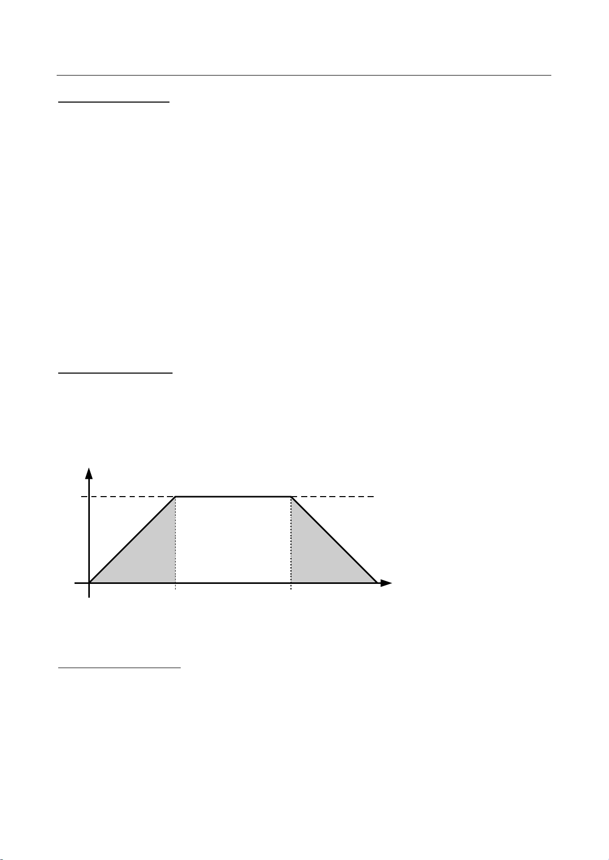
The maximum speed refers to the tool path traveled. The maximum speed is used as fast traverse
speed during automatic program execution.
The maximum speed serves as reference value for the calculation of the acceleration based on the
run-up time (see constant 42)
The maximum speed serves as reference value for the calculation of the second acceleration based
on the second acceleration time (MC 78) (see second acceleration).
The maximum speed serves as reference value for the calculation of the acceleration based on the
emergency braking time (MC 155) (see emergency braking time).
The maximum speed may not be set higher than the lowest of the axis speeds, since there is no
check during automatic pro cessing.
42 Acceleration time
Here the time required for the machine to reach the maximum speed (MC 41) is entered in
milliseconds. The calculation of the machine acceleration for all operating situations is based on this
value.
v
v
max
MAS 42 MAS 42
v
= (MAS 41)
max
t
43 Manual fast motion
Speed under manual control in fast traverse mode (fast traverse key ON).
The fast traverse speed refers to the individual axes. Accordingly, the tool path time can be higher
than the fast traverse speed. It cannot exceed the maximum speed of the machine, however (see
constant 41).
41&63A0204 (vision_le_m_us_inb.doc )
Page 67

VISION LE
(
)
45
MAS
⋅
MAS
45
Startup
System of the VISION LE Page 63
44 Manual feed
Maximum speed of manual control without fast traverse mode (fast traverse key OFF).
45 Teach trace KV
The value of this constant defines the amplifying factor of the position control loop as a ratio of speed
and positional deviation. The constant is stated in units of [1/sec].
During scanning the deviation can be regarded as the radius of the optical scanning circle. For higher
speeds, this circle (R = 1 mm) is advanced in the traveling direction in order to gain a higher
deviation. The maximum advance is 6 mm.
The LA value must be set in such a way that the machine can be moved free from vibrations at the
specified maximum scanning speed. If the LA value is set to < 5, the maximum scanning speed is
indirectly raised according to the following formula:
current
300
v
advancepresent
v
v
=
The current speed is set in the Teach-Trace menu. Raising the maximum scanning speed is only
necessary for scanning speeds of less than 300 mm/min.
Specify the maximum scanning speed together with the LA value.
Radius ==
At MAS45 = 5 and with a radius of = 6 mm the maximum scanning speed is 30 mm/sec, or 1800
mm/min.
46 Teach quer KV
The value of this constant defines the amplifying factor of the position control loop as a ratio of speed
and positional deviation. The constant is stated in units of [1/10sec].
Additive traverse control is effective in particular at low speeds. If you need to scan mainly at lower
speeds the normal forward control is not sufficient to keep scanning on a line. In such a case, enter a
smaller value.
Notice: Loop amplification in the traverse direction should be set to approx. ¼ of the loop
amplification of the machine.
47 Portal deviation
Monitoring a gantry with two separate drives (absolute gantry control) is provided as an optional
feature. The two gantry axes are accessed and controlled separately. In this process, the position of
the two axes to one another is constantly monitored and the deviation is compared with the value
preset in this machine constant. If the limit has been exceeded "(109) Loop error P“ is displayed and
all drives are deactivated via the controller release.
41&63A0204 (vision_le_m_us_inb.doc )
Page 68
VISION LE
Startup
System of the VISION LE Page 64
48 Smoothing factor
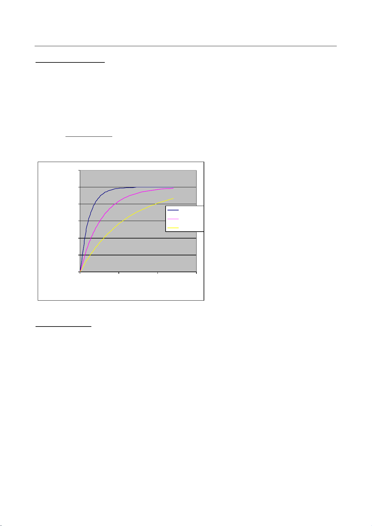
Acceleration of the individual axes is "smoothened" with the smoothing factor, i.e. the starting and
stopping procedure is carried out more gently. The smoothing factor must not be e xcessively large in
order to avoid contour inaccuracies with circles. Depending on the machine and application, values
between 1 and 3 are recommended (1=hard, 3=soft).
Formula:
vv
−
48
iett
v
i
v +
=
i
+
1
arg
MAS
2
1200,00
1000,00
800,00
600,00
Actual speed
400,00
200,00
0,00
0 0,1 0,2 0,3
Time [sec]
49 Machine unit
Here the resolution (precision) of the sub-programs carried out on the machine is to be entered. It
also serves as interpretation default for coordinate values within the ESSI programs.
1 one decimal place (1/10 mm)
2 two decimal places (1/100 mm)
Faktor 1
Faktor 2
Faktor 3
3 three decimal places (1/1000 mm)
41&63A0204 (vision_le_m_us_inb.doc )
Page 69

VISION LE
Startup
System of the VISION LE Page 65
51 Cable error suppression
The encoder pulses are transferred to the control system as push-pull signals. The control system
checks whether the si gnals are almost the same in opposition, and thus gains information about the
condition of the lines (strand breakage!).
It maybe useful to relax monitoring of the encoder and cabling to the control system during startup. In
this special case, "1" can be entered in this constant so that cable errors are su ppressed. For safety
reasons, however, a zero must be entered here during regular operation.
52 Reference
Setting the value of this constant to 1 indicates that a reference point system has been installed.
Small machines are sometimes not equipped with a reference point cam. If you want to stop the
control system from running check tests, enter "0" (= no reference point system) here.
Even though a reference point system is not available, a reference point can be defined by means of
a manual reference point movement (confirm current machine position on the reference screen with
the F1 key).
The option “Automatic reference point movement” (C0.521.00) can be deactivated by setting the
machine constant 52 to “2.” Manual reference point movement is po ssible.
53 Loop behavior
This constant controls the behavior of the control loop.
0 The position control loop is enabled in automatic as well as in manual mode. The
control loops will only be disabled in case of errors or interrupted voltage supply.
1 In manual mode, the position control loops are only enabled when a moving
command has been given.
54 Tipp/Latch (operation)
This constant controls the type of manual traversing.
0 Jogging mode. Movement of the machine starts when the cursor key is operated. The
machine stops as soon as the cursor key is released.
1 Latch mode. The traversing direction is preselected with the cursor keys. The
movement itself is triggered with the start key.
41&63A0204 (vision_le_m_us_inb.doc )
Page 70
VISION LE
t
155
Startup
System of the VISION LE Page 66
55 AC drives
This constant is in particular intended for modern-day indexing mechanisms that combine motor and
encoder as one unit. When the drives are disabled, the encoder is simultaneously disconnected from
the supply. After reconnecting the power supply, make sure to wait until the encoders of the drives
are operational again!
0 DC drives, i.e. no reference point movement after power outage
1 AC drives, i.e. reference point movement necessary after power outage. The axes are
released approx. ½ second after the 24 volt power su pply is switched on.
62 2. acceleration time
78 Speed 2. acceleration
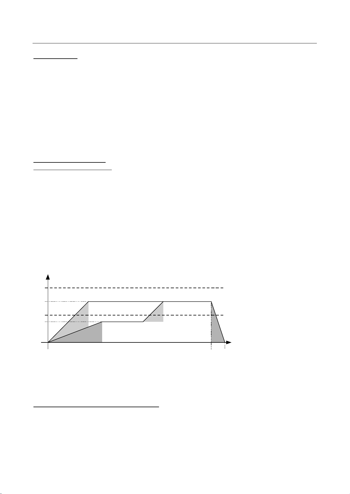
A second acceleration ramp can be defined by combining co nstants 62 and 78.
The second acceleration is active when the speed is greater than the value in constant 62 (limiting
speed for second acce leration).
The value for the second acceleration is derived from the con stant 41 (maximum speed) and the
constant 78 (acceleration time).
Units
Constant 62 [mm/min]
Constant 78 [ms]
v
v
max
v
targ1
v
v
2
targ2
MAS 42
MAS 78
v
= (MAS 41)
max
v2= (MAS 62)
v
targ1
and v
are programmed speeds
targ2
MAS 42
MAS
See also constant 155 (Emergency deceleration).
64,65 Automatic reference point movement
An automatic reference point movement can be installed as add-on in the control and on the
machine. For regular operation, the constants explained below are irrelevant.
41&63A0204 (vision_le_m_us_inb.doc )
Page 71

VISION LE
Startup
System of the VISION LE Page 67
For an automatic reference point movement, the reference cams on the machine have to be
prepared. The controlling system must be able to recognize on which side of the actual reference
point (flank and first range of the cam) the machine is positioned.
In this procedure, the system first checks whether the machine is located on a cam and then moves
it away from the cam in the opposite direction. Only then the actual reference point movement in
direction of the cam is executed. The procedure is completed when the reference point with the
encoder zero pulse has been recognized.
The machine constants define with a corresponding number which of the axes can start the
reference point movement first (1) and which second (2).
A sign indicates in which direction the reference cam is to be searched if the machine has not yet
found it.
68 - 77 Tool offsets
These constants define the mechanical distance of the individual tools to the main cutting tool. The
point is that a program should not have to know the position of the individual tools in use with regard
to the position of the other tools, in order to produce a workpiece that complies with the geometric
specifications. These distances are calculated and positioned independently by the control system
when an offset is requested by the program. If offsets are assigned to processes (version V3 only),
the appropriate offset is selected and traveled after each change of processes.
78 Speed 2. acceleration
See machine constant 62
79 Deviation X1/X2
In this constant the value of the maximum deviation of the two drives is entered which is
compensated according to the reference in the case of operation. If the gantry axes show a greater
deviation than specified, an error message is generated.
155 Emergency deceleration
MC 41 (maximum speed) combined with this machine constant defines the emergency deceleration.
This deceleration is activated by the MIP (e.g. water table detection).
156 X backlash comp
157 Y backlash comp
159 P backlash comp
Enter the inaccuracies found between motor, encoder and gear rack for the axes X, Y, and P. These
values are used for compensating inaccuracies.
When switching between forward and backward movement of the axes inaccuracies occur between
the distance indicated by the control system and the distance actually traveled by the machine.
41&63A0204 (vision_le_m_us_inb.doc )
Page 72

VISION LE
Startup
System of the VISION LE Page 68
Determine the differences and enter the value determined for each individual axis in the re spective
constant.
160 Time on edge
The dwell time of the machine at corners can be entered here.
161 Min. angle stop on edge
If the specified angle is exceeded during a change of direction of the programmed geometry, the
control system will execute a corner stop.
169 Laser pointer offset x [1/1000mm]
A separate, non-programmable offset is provided for the light pointer. The operator turns this offset
on by pressing a key. The constants designate the distance between the light pointer and the
reference tool in the X and Y directions.
This offset is used with tool position correction.
Constant MIP 19 does not apply.
186 Limit search speed Teach Trace
The value of this constant defines the speed under which the system no longer cuts in half the speed
specified in the Teach-Trace menu. If this constant is not available or is zero, the limit is set to 500
mm/min (approx. 20 ipm). If the speed is lower than the speed specified in the constant it is not
reduced to half the speed.
232 X nega te output volt.
233 Y negate output volt.
To control pre-configured drive units (e.g: HL90) the output voltage is negated
0 positive set value for positive movement direction
negativer set value for negative movement direction
1 negative set value for positive movement direction
positive set value for negative positive movement direction
41&63A0204 (vision_le_m_us_inb.doc )
Page 73

VISION LE
Startup
System of the VISION LE Page 69
5.4 MIP Constants (MIP.KON)
List of MIP constants
01 NOT USED
02 NOT USED
03 NOT USED
04 NOT USED
05 NOT USED
06 NOT USED
07 NOT USED
08 NOT USED
09 NOT USED
10 ORDINAL NO. FOR ACCELERATION/BRAKE DISTANCE
11 NOT USED
12 NOT USED
13 NOT USED
14 NOT USED
15 NOT USED
16 PRESTOP [MSEC]
17 DIST. BEFORE LINE [1/1000MM]
18 DIST. AFTER LINE [1/1000MM]
19 NOT USED
20 NOT USED
21 NOT USED
22 LOGICAL PROCESS NUMBER
23 ON-THE-FLY AF 1
24 ON-THE-FLY AF 2
25 ON-THE-FLY AF 3
26 ON-THE-FLY AF 4
27 ON-THE-FLY AF 5
28 ON-THE-FLY AF 6
29 ON-THE-FLY AF 7
30 ON-THE-FLY AF 8
31 AF IN EXCHANGE FOR AF 7
32 AF IN EXCHANGE FOR AF 8
33 NOT USED
34 NOT USED
35 MIP OVERRIDE 1
36 MIP OVERRIDE 2
37 MIP OVERRIDE 3
38 NOT USED
39 NOT USED
40 INFORMATION FIELD 1
41 INFORMATION FIELD 2
42 INFORMATION FIELD 3
43 INFORMATION FIELD 4
44 INFORMATION FIELD 5
45 INFORMATION FIELD 6
46 INFORMATION FIELD 7
47 INFORMATION FIELD 8
41&63A0204 (vision_le_m_us_inb.doc )
Page 74

VISION LE
Startup
System of the VISION LE Page 70
48 INFORMATION FIELD 9
59 INFORMATION FIELD 10
50 INFORMATION FIELD 11
51 INFORMATION FIELD 12
52 INFORMATION FIELD 13
53 INFORMATION FIELD 14
54 INFORMATION FIELD 15
55 INFORMATION FIELD 16
56 NOT USED
57 MIP SETTING 1
58 MIP SETTING 2
59 MIP SETTING 3
60 MIP SETTING 4
61 MIP SETTING 5
62 MIP SETTING 6
63 MIP SETTING 7
64 MIP SETTING 8
65 MIP SETTING 9
66 MIP SETTING 10
67 MIP SETTING 11
68 MIP SETTING 12
69 MIP SETTING 13
70 MIP SETTING 14
71 MIP SETTING 15
72 MIP SETTING 16
122 MACHINE WITH CLUTCH (0/1)
123 DISTANCE TO AF STOP [1/1000MM]
41&63A0204 (vision_le_m_us_inb.doc )
Page 75

VISION LE
Startup
System of the VISION LE Page 71
Description of the MIP Constants
10 Ordinal no. for acceleration/brake distance
Process values and time values are stored in the cutting packages. Process values that have an
influence on the geometry processing are stored in the cutting package with a variable process value
number:
Die Beschleunigung während dem Handsteuern wird durch die Maschinenkonstante MAS42
definiert. Im Au tomatikbetrieb wird die Beschleunigung (bzw. Hochlaufzeit) aus den Schneiddaten
entnommen.
Diese Konstante gibt die Num mer des Schneidwertes an, der die Hochlaufzeit in Millisekunden
definiert.
16 Prestop
In this constant the time before a function that switches off the process is determined in milliseconds.
This function is used to reduce the pressure in time so no burning damage occurs in the position the
process is switched off. The condition is reported to the MIP by the marker 885.
Auxilliary functions with which this function works:
On Off On Off
7 8 70 75
7 54 71 75
9 10 90 91
9 111 100 10
13 14 100 111
15 16 157 159
35 36 158 159
53 8
53 54
17 Distance before line
This constant determines the distance in 1/1000 mm before the next line (next corner).
This function is used to switch off the automatic height control at corners. This is reported to the MIP
by the marker 859.
18 Distance after line
This constant determines the distance in 1/000 mm after the last line (last corner).
This funktion is used to switch off the height control at corners. This is reported to the MIP by the
marker 859.
22 Logical process number
The input format of the editor is the hexadecimal format. For example, the number “6” is entered in
order to obtain the process “oxy-fuel” and “punch marking” (0110).
On the VISION LE the maximum number of processes is limited to three. Any combination of
processes is possible (for example 1+2+5).
41&63A0204 (vision_le_m_us_inb.doc )
Page 76

VISION LE
Startup
System of the VISION LE Page 72
A process is set up by the system under the following conditions:
1. The process number must be entered into the MIP machine co nstant 22.
2. The process must be defined in the MIP.
3. The process must be defined in the cutting package (Nx in PARAM.CUT; x=process
number).
4. The maximum number of processes must not be exhausted.
23 - 30 Auxiliary functions without machine stop
Usually, auxiliary functions are issued when the machine has stopped. In specific cases this is not
the desired procedure, however. Then certain auxiliary functions are issued on-the-fly. These are, for
example, instructions to the height control, when the active cutting process should not be interrupted
by a ma chine stoppage.
ESSI functions that are issued without machine stoppage are entered into these MIP constants in
random order.
31 AF in exchange for AF 7
32 AF in exchange for AF 8
When the Teach Trace mode is turned on, the auxiliary functions 7 and 8 are replaced by the
auxiliary functions entered here.
If a fixed program with variable cut is called, the auxiliary functions 7 and 8 are replaced by the
auxiliary functions entered here.
35-55 MIP override 1-16
If a marker for speed reduction is reached within a program, the processing speed of the machine is
reduced to the indicated percentage. The speed reduction can differ for each of the 16 constants.
57 - 72 MIP setting
The machine interface program MIP can be parameterized with these 16 constants so that
alternative forms of behavior can be selected in dependence of the machine constellation. The
meaning of the individual constants is, thus, defined by the installed MIP. Only 0 and 1 can be
entered in the constants.
122 Machine with clutch (0/1)
This constant defines whether there is a gear clutch present on the machine. This is used in order to
uncouple the drives and shift the machine by hand. The uncoupling is accomplished by means of a
keypress on the control panel.
123 Distance to AF stop
41&63A0204 (vision_le_m_us_inb.doc )
Page 77

VISION LE
Startup
System of the VISION LE Page 73
This constant defines a distance before a machine stop (for example by means of an auxiliary
function or traversing a corner). During this travel the height control is deactivated.
This function is used in order to deactivate the automatic height control. This makes it possible to
traverse kerfs. Dem MIP wird der Zustand durch den Merker 962 mitgeteilt.
It is entered in 1/1000 mi llimeter [mm].
The auxilliary functions with which this function works are:
On Off On Off
7 8 70 75
7 54 71 75
9 10 90 91
9 111 100 10
13 14 100 111
15 16 157 159
35 36 158 159
53 8
53 54
41&63A0204 (vision_le_m_us_inb.doc )
Page 78

VISION LE
Startup
System of the VISION LE Page 74
5.5 Device Constants (DEV.KON)
List of constants for serial interfaces.
01 COM1 DEVICE
02 BAUD RATE
03 PARITY N/O/E 0/1/2
04 DATA BITS
05 START/STOP BITS
06 HSK NO/XON-XOFF 0/1
07 TIMEOUT (SEC)
08 NOT USED
09 COM2 DEVICE
10 BAUD RATE
11 PARITY N/O/E 0/1/2
12 DATA BITS
13 START/STOP BITS
14 HSK NO/XON-XOFF 0/1
15 TIMEOUT (SEC)
16 NOT USED
17 NOT USED
18 NOT USED
19 NOT USED
20 NOT USED
21 NOT USED
22 NOT USED
23 NOT USED
24 NOT USED
25 NOT USED
26 NOT USED
27 NOT USED
28 NOT USED
29 NOT USED
30 NOT USED
31 NOT USED
32 NOT USED
33 UDL/COLUMBUS 0/1
34 END CHARACTER
35 NUMBER OF END CHARACTERS
41&63A0204 (vision_le_m_us_inb.doc )
Page 79

VISION LE
Startup
System of the VISION LE Page 75
Description of the Device Constants
The VISION LE supports a maximum of two serial interfaces, COM1 and COM2.
1,9 Device
With these constants, an interface is allocated to the used driver in the system of the VISION LE.
3 Serial data transfer without protocol. The connected device should support transfer
control with XON / XOFF. See below.
4 UDL (Up Down Load). UDL enables a secured data transfer between the control and
a computer. An appropriate UDL host program is necessary on the computer. Data
transfer to the host computer is controlled with UDL by the control.
5 ASOD (ATAS Serial Online Debugger). ASOD is a tool integrated especially for
testing and startup purposes.
6 Terminal. Every arriving character is displayed, every keypress is sent. No processing
of the characters occurs. Useful for testing the interfaces.
17 DDE2. Transfer of data with the protocol appropriate to the ANCDDE2 Server.
Reporting, monitoring, PPT, UDL and DNC modes.
18 SERVICE. Interface test. All received characters are returned 1:1.
21 DDE3. Transfer of data with the protocol appropriate to the ANCDDE3 Server (32-bit
server). Reporting, monitoring, PPT and UDL with long file names and DNC mode.
Report data are stored temporarily when there is no connection. UDL and reporting
run simu ltaneously.
2,10 Baud rate
The transfer speed of a serial connection is defined by the baud rate. The baud rate has to be set to
the same value on both sides. All serial interfaces in the control system support the following baud
rates:
300 baud
1200 baud
2400 baud
4800 baud
9600 baud
19200 baud (for COM1 and COM2 only)
41&63A0204 (vision_le_m_us_inb.doc )
Page 80

VISION LE
Startup
System of the VISION LE Page 76
3,11 Parity
Individual characters can be protected by a parity bit during transmission. As for the baud rate, both
partners, control and data device, must have the same setting. The following three settings are
possible:
0 No parity supplement
1 Odd parity supplement
2 Even parity supplement
4,12 Data bits
This constant defines the number of data bits for a character. Seven bits are sufficient for program
data since only the ASCII data record is being used and no special characters or graphics are
transmitted. The number of transferred bits per character have to be identical between the control
and the connected device or computer. The control admits the following two values:
7 Seven data bits
8 Eight data bits
5,13 Number of stop bits
Each character in serial transfer is completed with a stop bit. For the control, the two valid values are:
1 One stop bit
2 Two stop bits
In most cases, the choice of stop bits depends on the setting of the connected device. Remember
that the sum of data bits, parity bits and stop bits per character may not exceed eleven.
6,14 Handshake
During transfer of a serial data stream, it may be necessary to give the two partners the time to
process or store the received characters. In many cases this takes longer than the transmission of an
individual character, so that transfer has to be interrupted for this processing procedure. The control
characters XON and XOFF are provided for this type of control.
Examples: During transfer to the control system, the latter sends the XOFF character to the sending
device in order to communicate that the data received before must first be written from a buffer to
internal storage (floppy disk) first. During this time no more than five subsequent characters can be
buffered. After completion of the storage procedure, the control system sends the XON character.
The connected device must therefore interrupt the transfer in the time period between receiving
XOFF and XON.
0 No handshake possible
1 Handshake with XON / XOFF is available
2 Hardware handshake RTS / CTS (for COM1 and COM2 only)
If handshaking is not available, tests may be needed to determine the maximum baud rate that can
be used for transfer without losing data. This baud rate must not be exceeded. The DOS "COPY"
41&63A0204 (vision_le_m_us_inb.doc )
Page 81

VISION LE
Startup
System of the VISION LE Page 77
command does not support the control procedure with XON / XOFF! Make sure to use the
appropriate cable with the appropriate number of leads for options 1 and 2.
7,15 Timeout
This constant defines the period of time, the system waits if a UDL connection could not be
established. It then sends an error message.
With serial transfer, this time is used in order to determine a transmission end. (see also constants
33/34).
33 UDL Setting
With this constant the various types of the UDL protocol can be set.
0 UDL host system versions 3 & 4
1 UDL host system in connection with the programming te rminal Columbus
2 UDL host system with terminal display on the control system
3 UDL host system in connection with the programming terminal Columbus
including the terminal display on the control system
Long file names must not end with blank characters.
34,35 End character, number of end characters
The end of the serial data transfer with the driver 3 (XON / XOFF) cannot be specified
unambiguously.
- The data stream ends with CTRL Z, code 1AH. The control system interprets this
character as the end of the data and completely ends the transfer in the control
system.
- It is not possible to insert the character CTRL Z as an end-of-message marker in
existing data blocks. So the procedure used with punched tape has established itself
here as well: To identify the end of the data, a certain number of characters (ZEROs
or BLANKs) are used. Constant 34 defines the character itself and constant 35 the
minimum nu mber of such characters.
Example
Constant 34 contains the value 048 (the ASCII code for the number 0) and constant
35 contains the value 20. The control system recognizes the end of a transmission by
the 20 repeated zeros. The zeros themselves, as well as any subsequent data, are
not accepted.
41&63A0204 (vision_le_m_us_inb.doc )
Page 82

VISION LE
Startup
System of the VISION LE Page 78
5.6 Configuration (ANCDEF.KON)
01 PORTAL AXIS
02 RESERVED
03 RESERVED
04 AUTOMATIC REFERENCE
05 PLATE ALIGNMENT
06 AXIS ROTATION
07 RESERVED
08 CORRECTION PROGRAM EXECUTION
09 RESERVED
10 RESERVED
11 RESERVED
12 RESERVED
13 RESERVED
14 TEACHTRACE, TRACE
15 PARKING PROGRAM EXECUTION
16 RESERVED
17 RESERVED
18 ADJUSTABLE PROGRAM ZERO POINT
19 PROGRAM ROTATION
20 RESERVED
21 RESERVED
22 RESERVED
23 EIA FORMAT
24 RESERVED
25 PARALLEL MDI
26 RESERVED
27 RESERVED
28 RESERVED
29 RESERVED
30 RESERVED
31 RESERVED
32 XON/XOFF
33 UDL
34 RESERVED
35 RESERVED
36 RESERVED
37 RESERVED
38 RESERVED
39 RESERVED
40 RESERVED
41 RESERVED
42 RESERVED
43 RESERVED
44 DDE-LOGGING
45 RESERVED
46 RESERVED
47 RESERVED
48 RESERVED
49 RESERVED
50 RESERVED
41&63A0204 (vision_le_m_us_inb.doc )
Page 83

VISION LE
Startup
System of the VISION LE Page 79
51 RESERVED
52 RESERVED
53 RESERVED
54 RESERVED
55 RESERVED
56 RESERVED
57 RESERVED
58 RESERVED
59 RESERVED
60 RESERVED
61 RESERVED
62 RESERVED
63 ADDITIONAL COM-PORTS
64 COMMISSION
41&63A0204 (vision_le_m_us_inb.doc )
Page 84

VISION LE
Startup
Error messages Page 80
6 Error Messages (Codes of Disk Errors)
(155) FLOPPY DISK <0>: GENERAL ERROR <m>
Error when accessing the memory. Floppy disk 0 is the internal memory. Possibly, the control system
is no longer operational.
The error number <m> is displayed as an 16 bit integer value in hexadecimal format. While possibly
two errors may occur, the values are seperated in LowWord and HighWord. The HighWord includes
the BIOS-Messagecodes and the LowWord the error numbers from the IRQ-Service.
Description of the hexadecimal error numbers
a) Floppy disk errors (internal device is refered to as floppy disk 0):
error number
description (part I)
(HighWord)
01 invalid drive number
02 error reading boot sector
03 error reading FAT
04 error reading ROOT-DIR
05 read/write error, status != 0
06 disk changed
09 invalid ADOS-function
0B invalid size of RootDir (>224 entries)
16 invalid start cluster
2A invalid cluster index
34 invalid cluster access
41&63A0204 (vision_le_m_us_inb.doc )
Page 85
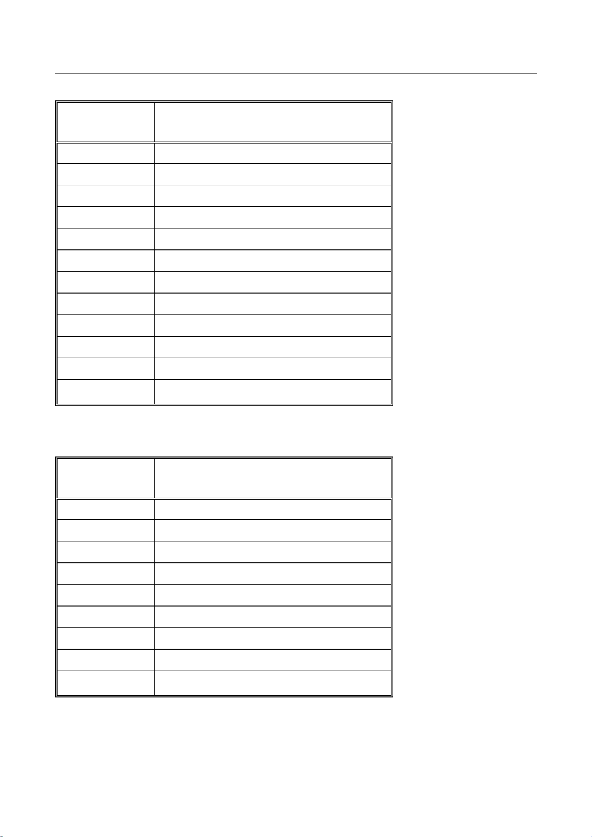
VISION LE
Startup
Error messages Page 81
error number
description (part II)
(HighWord)
3E error writing FAT
3F error writing DIR
49 error writing DIR
51 error writing FAT
52 error writing DIR
5B formating aborted with error
5C invalid disk format
5D drive missing
5E error reading BOOT/FAT/DIR
5F error reading BOOT/FAT/DIR
60 error reading BOOT/FAT/DIR
61 invalid volume label
error number
description
(LowWord)
01 invalid function code
02 address not found
04 sector not found
06 disk changed
08 DMA overflow
09 segmentation violation
10 error while reading
20 controller failure
40 Track not found
41&63A0204 (vision_le_m_us_inb.doc )
Page 86

VISION LE
Startup
Error messages Page 82
b) Boot errors
error number
description
(LowWord)
B1 error reading FAT
B2 error reading DIR
B3 error reading boot sector
B4 error during disk reset
B5 error reading a single sector
B6 error in file structur
B7 error in file structur
B8 error in file structur
B9 error while comparing FATs
F1 error reading FAT
F2 error reading DIR
F3 error reading boot sector
F4 error during disk reset
F5 error reading a single sector
F6 error in file structur
F7 error in file structur
F8 error in file structur
F9 error while comparing FATs
41&63A0204 (vision_le_m_us_inb.doc )
Page 87
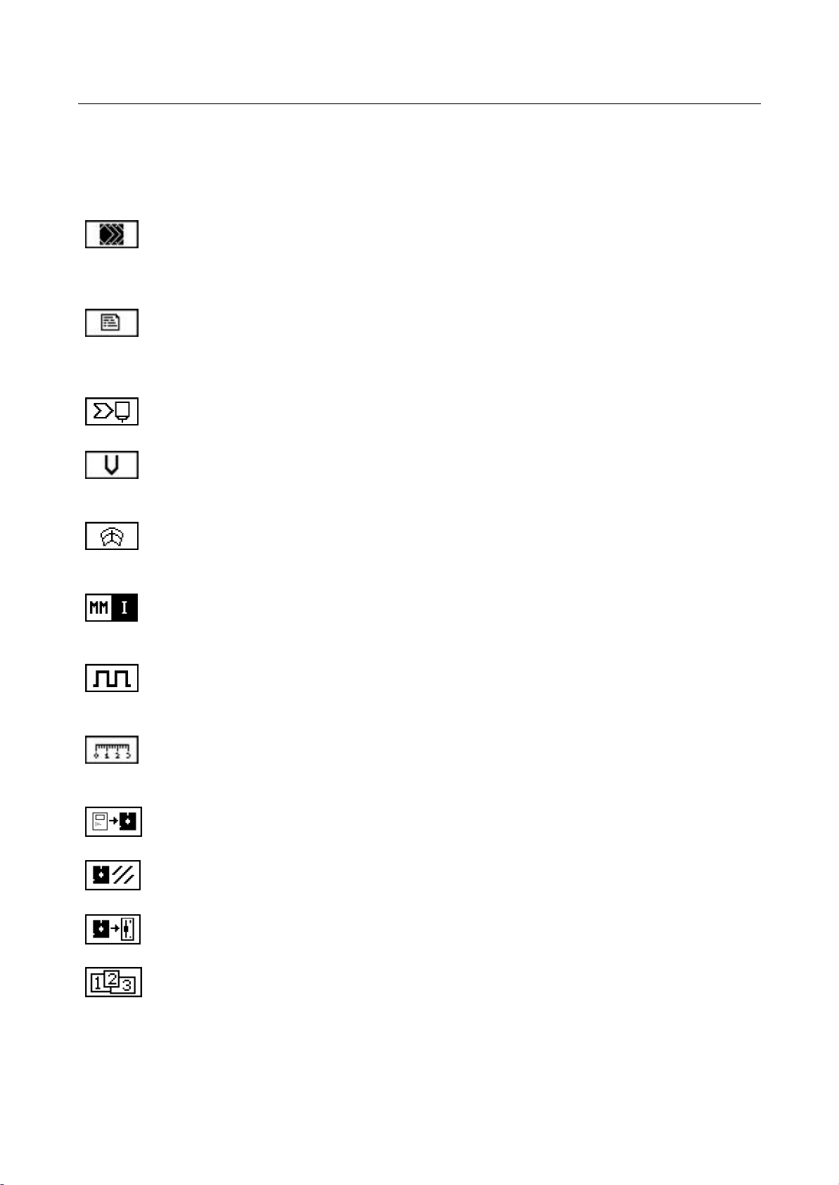
VISION LE
Startup
Symbol overview Page 83
7 Symbol Overview
7.1 Startup window
Startup window.
This symbol is displayed in the top left corner of the screen when the startup window
is the active window.
Constant editor.
For editing machine, device, system and MIP constants, as well as, displaying the
configuration.
Station parameters
Editing the station parameters and transmitting the parameter values to the stations.
Speed startup.
For determining the velocity of the axes.
Rotational speed startup.
For displaying the revolutional speed per axis with adjustable voltage supply.
MM/Inch selection
Changing between millimeter and inch geometry.
Impulse.
Clocked voltage supply for drive optimation.
Startup helps.
Working ranges, reference point, tool offsets.
Copy System Files
Making backup of system files on several disks.
Format floppy
Formatting a disk in disk drive.
Insert Disk
Request for confirmation with the functions that create system disks and format disks.
Insert disk in disk drive.
Working ranges.
Graphical display of the adjusted working ranges and adjusting help.
41&63A0204 (vision_le_m_us_inb.doc )
Page 88
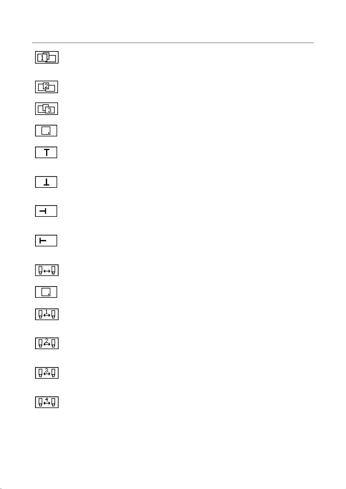
VISION LE
For adopting the current position of the X-axis as
positive
demarcation of the
For adopting the current position of the X-axis as
negative
demarcation of the
For adopting the current position of the Y-axis as
negative
demarcation of the
For adopting the current position of the Y-axis as
positive
demarcation of the
Startup
Symbol overview Page 84
Working ranges.
For adjusting the first working range.
Working ranges.
For adjusting the second working range.
Working ranges.
For adjusting the third working range.
Working ranges.
For adopting the fixed point (home position) for the selected working range.
Working ranges.
selected working range (software limit switch).
Working ranges.
selected working range.
Working ranges.
selected working range.
Working ranges.
selected working range.
Tool offsets.
For setting up tool offsets.
Tool offsets.
For adopting the reference point for setting the tool offsets.
Tool offsets.
For adopting the offset for the first tool.
Tool offsets.
For adopting the offset for the second tool.
Tool offsets.
For adopting the offset for the third tool.
Tool offsets.
For adopting the offset for the fourth tool.
41&63A0204 (vision_le_m_us_inb.doc )
Page 89

VISION LE
Startup
Symbol overview Page 85
Tool offsets.
For adopting the offset for the fifth tool.
Reference point adjustment.
For selecting a reference point adjustment followed by a reference point movement.
Reference point adjustment.
The current position of the machine is adopted as machine zero point.
41&63A0204 (vision_le_m_us_inb.doc )
Page 90
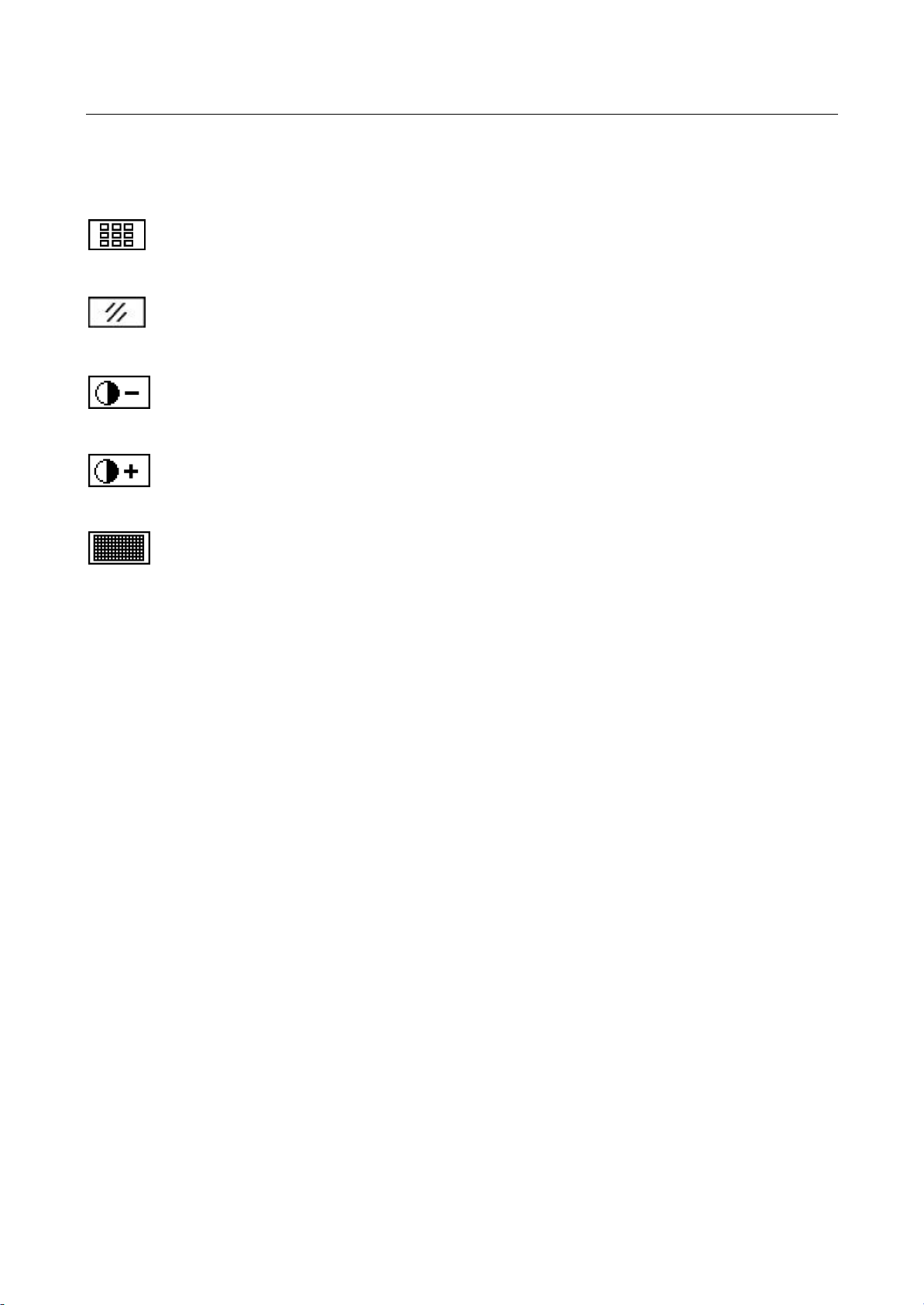
VISION LE
Startup
Symbol overview Page 86
7.2 Deviation Display / LCD Test (Shift/F1)
Test button
Check the functioning of the keys and controls.
Delete display of maximum value
Clear the displayed maximum value.
LCD Test.
Contrast minus.
LCD Test.
Contrast plus.
LCD Test.
Display of basic font. All black, all white.
41&63A0204 (vision_le_m_us_inb.doc )
Page 91
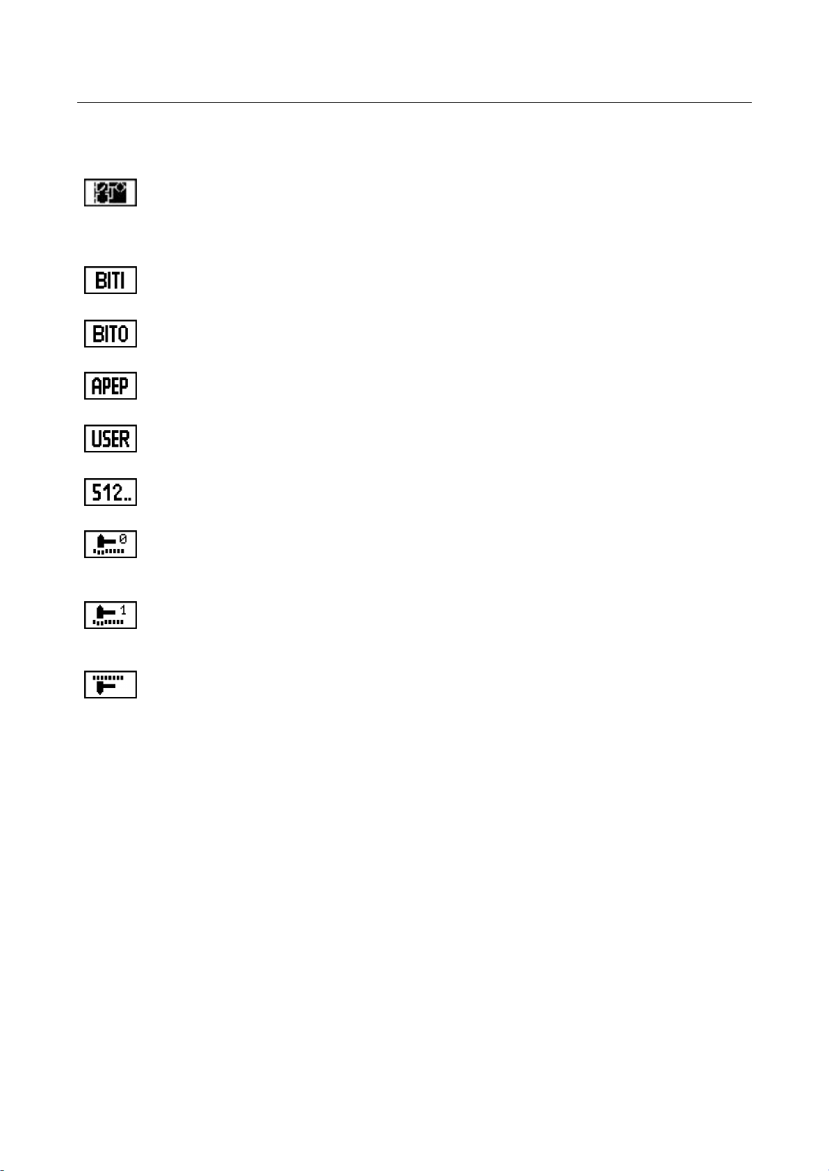
VISION LE
Startup
Symbol overview Page 87
7.3 MIP Signal Display (Shift/F2)
Signal display window.
This symbol is displayed in the top left corner of the screen when the window of the
MIP signal display is the active window.
ASIOB Input
ASIOB output
Display of static input and output.
Display of internal MIP signals.
Display of MIP signals higher than 512.
Force.
For forcing value 0.
Force.
For forcing value 1.
Force off.
For cancelling the force instruction.
41&63A0204 (vision_le_m_us_inb.doc )
Page 92

VISION LE
Startup
Symbol overview Page 88
7.4 AF/KF Control (Shift/F3)
AF/KF.
Display of the last 16 auxiliary and key functions. This symbol is displayed in the top
left corner of the screen when the AF/KF control window is the active window.
AF.
For displaying the auxiliary functions sent last to the MIP.
KF.
For displaying the key functions sent last to the MIP.
MF
For displaying the miscellaneous functions sent last to the MIP
41&63A0204 (vision_le_m_us_inb.doc )
Page 93

VISION LE
Startup
Symbol overview Page 89
7.5 Synchronization Display (Shift/F4)
Synchronization display
This symbol is displayed in the top left corner of the screen when the "synchronization
control" window is the active window.
ASIOB
Delete display of ASIOB maximum value
Panel
Delete display of panel maximum value
41&63A0204 (vision_le_m_us_inb.doc )
Page 94
VISION LE
Startup
Symbol overview Page 90
7.6 Mini Operating System (Shift/F5)
Mini operating system.
For displaying internal RAM addresses. This symbol is displayed in the top left corner
of the screen when the window of the mini operating system is the active window.
Mini operating system.
For switching between the displays of byte, word, long.
Mini operating system.
For switching to absolute addresses.
Mini operating system.
For changing the value.
41&63A0204 (vision_le_m_us_inb.doc )
Page 95

VISION LE
Startup
Index Page 91
8 Index
Accident prevention..............................................................................................................................2
AF-KF control.....................................................................................................................................31
Application and usage conditions........................................................................................................4
ASIOB................................................................................................................................................29
Auxiliary function.................................................................................................................................31
Configuration......................................................................................................................................67
Configuration constants.....................................................................................................................14
Constant types ...................................................................................................................................14
Constants editor.................................................................................................................................13
Contrast..............................................................................................................................................28
Controller release...............................................................................................................................35
Danger warnings..................................................................................................................................2
Device constants .........................................................................................................................14, 63
Editor
constants........................................................................................................................................13
Emergency measures..........................................................................................................................4
Error display.......................................................................................................................................34
Error messages .................................................................................................................................69
Boot errors......................................................................................................................................71
floppy disk .......................................................................................................................................69
Floppy disk.....................................................................................................................................69
Feed release......................................................................................................................................36
Input....................................................................................................................................................29
Keys ...................................................................................................................................................31
LCD
test..................................................................................................................................................28
Machine constants.......................................................................................................................14, 48
Machine zero point.............................................................................................................................24
Mini operating system ........................................................................................................................32
MIP constants.....................................................................................................................................59
MIP signal display..............................................................................................................................29
MIP-constants....................................................................................................................................14
Output.................................................................................................................................................29
Pixel test.............................................................................................................................................28
Release
controller.........................................................................................................................................35
feed.................................................................................................................................................36
SPC................................................................................................................................................35
Rotational speed display....................................................................................................................17
Safety...................................................................................................................................................1
Safety precautions ...............................................................................................................................1
Service window..................................................................................................................................26
Signal display.....................................................................................................................................29
SPC release.......................................................................................................................................35
Speed measurement.........................................................................................................................17
Startup help........................................................................................................................................20
Startup window...................................................................................................................................11
Status display.....................................................................................................................................34
System constants ........................................................................................................................14, 40
System files........................................................................................................................................39
41&63A0204 (vision_le_m_us_inb.doc )
Page 96

VISION LE
Startup
Index Page 92
Time setting........................................................................................................................................37
Tool offsets.........................................................................................................................................25
Turn-on voltage..................................................................................................................................35
Window
service............................................................................................................................................26
startup.............................................................................................................................................11
Working ranges..................................................................................................................................22
41&63A0204 (vision_le_m_us_inb.doc )
Page 97

Page 98

Customer / Technical Support
(843)-664-4405
(800) ESAB-123 (372-2123)
ESAB Welding and Cutting Products
PO Box 100545 Ebenezer Rd
Florence, SC 29501-0545
http://www.esab.com
http://www.esabcutting.com
ESAB Cutting Systems - Canada
6010 Tomken Road
Mississauga, Ontario Canada L5T 1X9
Phone: (905) 670-0220
Fax: (905) 670-4879
ESAB-Cutting Systems GmbH
Robert-Bosch-Strasse 20
Postfach 1128
D-61184 Karben 1
Phone 011-49-6039-400
Fax 011-49-6039-403-02
http://www.esab.com
Printed in U.S.A.
Page 99
Vision LE
Computer Numerical Control
Operation and Parts Manual
LE-Basic Module
LE-X LE-FX
Form Number 0558005198
Date: 10/04
Updated 12/05
LE-F
LE-Color Basic Module
LE-CF
LE-CX LE-CFX
Operation
Replacement Parts
Page 100

The equipment described in this manual is
potentially hazardous. Use caution when installing,
operating and maintaining this equipment.
The purchaser is solely responsible for the safe
operation and use of all products purchased,
including compliance with OSHA and other
government standards. ESAB Cutting Systems
has no liability for personal injury or other
damage arising out of the use of any product
manufactured or sold by ESAB. See standard
ESAB terms and conditions of sale for a specic
statement of ESAB’s responsibilities and
limitations on its liability.
ESAB Cutting Systems is not responsible for
any errors that may appear in this document.
Information in this document is subject to change
without notice.
This manual is ESAB Part No. 0558005198
This manual is for the convenience and use of the
cutting machine purchaser. It is not a contract
or other obligation on the part of ESAB Cutting
Systems.
* ESAB Cutting Systems, 2004
Printed In U.S.A.
 Loading...