


INSTRUCTION MANUAL
SVI 450i cvcc
Power Source
F15-071-D
December, 2003
This manual provides installation and operation / maintenance and troubleshooting instructions for the following units:
ESAB P/N 31950 - 208/230/460 V ac, 1 or 3 Phase, 60 Hz
ESAB P/N 31955 - 575 V ac, 3 Phase, 60 Hz (Refer to Supplement F-15-072.)
ESAB P/N 31960 - 220/380/415 V ac, 3 Phase, 50 Hz (Refer to Supplement F-15-073.)
L-TEC P/N 35618 - 220/380/415 V ac, 3 Phase, 50 Hz (Refer to Supplement F-15-073.)
These INSTRUCTIONS are for experienced operators. If you are not fully familiar with the principles of operation and safe
practices for arc welding equipment, we urge you to read our booklet, "Precautions and Safe Practices for Arc W elding,
Cutting, and Gouging," Form 52-529. Do NOT permit untrained persons to install, operate, or maintain this equipment. Do
NOT attempt to install or operate this equipment until you have read and fully understand these instructions. If you do not
fully understand these instructions, contact your supplier for further information. Be sure to read the Safety Precautions
before installing or operating this equipment.
Be sure this information reaches the operator.
You can get extra copies through your supplier.
ESAB Welding &
Cutting Products

USER RESPONSIBILITY
This equipment will perform in conformity with the description thereof contained in this manual and accompanying
labels and/or inserts when installed, operated, maintained and repaired in accordance with the instructions provided.
This equipment must be checked periodically. Defective equipment should not be used. Parts that are broken,
missing, worn, distorted or contaminated should be replaced immediately. Should such repair or replacement become necessary, the manufacturer recommends that a telephone or written request for service advice be made to the
Authorized Distributor from whom purchased.
This equipment or any of its parts should not be altered without the prior written approval of the manufacturer. The
user of this equipment shall have the sole responsibility for any malfunction which results from improper use, faulty
maintenance, damage, improper repair or alteration by anyone other than the manufacturer or a service facility
designated by the manufacturer.
TABLE OF CONTENTS
SECTION TITLE PAGE
PARAGRAPH
SECTION 1 DESCRIPTION ................................................................................................. 5
1.1 Introduction ....................................................................................................... 5
1.2 Optional Accessories......................................................................................... 5
SECTION 2 INSTALLATION ................................................................................................ 6
2.1 General ............................................................................................................. 6
2.2 Unpacking and Placement ................................................................................ 6
2.3 Input Power Connections .................................................................................. 6
2.4 Output Welding Connections............................................................................. 8
2.5 MIG Control (J1) Interconnection ...................................................................... 9
2.6 Additional Remote Control (J2) Interconnection ................................................ 10
SECTION 3 OPERATION ..................................................................................................... 11
3.1 Introduction ....................................................................................................... 11
3.2 Duty Cycle ......................................................................................................... 11
3.3 Volt-Ampere (Slope) Characteristics ................................................................. 11
3.4 Power Source Welding Controls ....................................................................... 11
3.5 Sequence of Operation ..................................................................................... 12
SECTION 4 MAINTENANCE ................................................................................................ 15
4.1 General ............................................................................................................. 15
4.2 Cleaning ............................................................................................................ 15
4.3 Lubrication ........................................................................................................ 15
SECTION 5 TROUBLESHOOTING ..................................................................................... 16
5.1 Troubleshooting ................................................................................................ 16
SECTION 6 REPLACEMENT PARTS .................................................................................. 27
6.1 General ............................................................................................................. 27
6.2 Ordering ............................................................................................................ 27
2

WARNING: T hese Safety Precautions are for your
protection. They summarize precautionary infor-
mation from the references listed in Additional
Safety Information paragraph. Before performing any installation or operating procedures, be sure to read and follow the
safety precautions listed below as well as all other manuals,
material safety data sheets, labels, etc. Failure to observe
Safety Precautions can result in injury or death.
PROTECT YOURSELF AND OTHERS
—
Some welding, cutting, and gouging processes are noisy and require ear protection. The arc, like the sun, emits ultravio-
let (UV) and other radiation and can injure
skin and eyes. Hot metal can cause burns. Training in the
proper use of the processes and equipment is essential to
prevent accidents. Therefore:
1. Always wear safety glasses with side shields in any work
area, even if welding helmets, face shields, and goggles are
also required.
2. Use a face shield fitted with the correct filter and cover
plates to protect your eyes, face, neck, and ears from
sparks and rays of the arc when operating or observing
operations. WARN bystanders not to watch the arc and not
to expose themselves to the rays of the electric arc or hot
metal.
3. Wear flameproof gauntlet type gloves, heavy long-sleeved
shirt, cuffless trousers, high-topped shoes, and a welding
helmet or cap for hair protection, to protect against arc rays
and hot sparks or hot metal. A flameproof apron may also
be desirable as protection against radiated heat and sparks.
4. Hot sparks or metal can lodge in rolled up sleeves, trouser
cuffs, or pockets. Sleeves and collars should be kept
buttoned, and open pockets eliminated from the front of
clothing.
5. Protect other personnel from arc rays and hot sparks with a
suitable non-flammable partition or curtains.
6. Use goggles over safety glasses when chipping slag or
grinding. Chipped slag may be hot and can fly far. Bystanders should also wear goggles over safety glasses.
FIRES AND EXPLOSIONS -- Heat from
flames and arcs can start fires. Hot slag
or sparks can also cause fires and explosions. Therefore:
1. Remove all combustible materials well away from the work
area or cover the materials with a protective non-flammable
covering. Combustible materials include wood, cloth, sawdust, liquid and gas fuels, solvents, paints and coatings,
paper, etc.
2. Hot sparks or hot metal can fall through cracks or crevices
in floors or wall openings and cause a hidden smoldering
fire or fires on the floor below. Make certain that such
openings are protected from hot sparks and metal.
3. Do not weld, cut or perform other hot work until the workpiece
has been completely cleaned so that there are no substances on the workpiece which might produce flammable
or toxic vapors. Do not do hot work on closed containers.
They may explode.
4. Have fire extinguishing equipment handy for instant use,
such as a garden hose, water pail, sand bucket, or portable
fire extinguisher. Be sure you are trained in its use.
5. Do not use equipment beyond its ratings. For example,
overloaded welding cable can overheat and create a fire
hazard.
6. After completing operations, inspect the work area to make
certain there are no hot sparks or hot metal which could
cause a later fire. Use fire watchers when necessary.
7. For additional information, refer to NFPA Standard 51B,
"Fire Prevention in Use of Cutting and Welding Processes,"
available from the National Fire Protection Association,
Batterymarch Park, Quincy, MA 02269.
ELECTRICAL SHOCK — Contact can
cause severe injury or death. Do NOT use
AC output in damp areas, if movement is
confined, or if danger of falling exists. Put
on dry, hole-free gloves before turning on
the power. Also:
1. Be sure the power source frame (chassis) is connected to
the ground system of the input power.
2. Connect the workpiece to a good electrical ground.
3. Connect the work cable to the workpiece. A poor or missing
connection can expose the operator or others to a fatal
shock.
4. Use well-maintained equipment. Replace worn or damaged
cables.
5. Keep everything dry, including clothing, work area, cables,
torch/electrode holder and power source. Fix water leaks
immediately.
6. Make sure that you are well insulated, especially when
standing on metal or working in tight quarters or in a damp
area. Wear rubber-soled shoes and stand on a dry board or
insulating platform.
7. Turn off the power before removing your gloves.
8. Refer to ANSI/ASC Standard Z49.1 (see listing below) for
specific grounding recommendations. Do not mistake the
work lead for a ground cable.
ELECTRIC AND MAGNETIC FIELDS —
May be dangerous. Electric current flowing through any conductor causes localized Electric and Magnetic Fields (EMF).
Welding and cutting current creates EMF
around welding cables and welding machines. Therefore:
1. Welders having pacemakers should consult their physician
before welding. EMF may interfere with some pacemakers.
2. Exposure to EMF may have other health effects which are
unknown.
3. Welders should use the following procedures to minimize
exposure to EMF:
A. Route the electrode and work cables together. Secure
them with tape when possible.
B. Never coil the torch or work cable around your body.
C. Do not place your body between the torch and work
cables. Route cables on the same side of your body.
D. Connect the work cable to the workpiece as close as
possible to the area being welded.
E. Keep welding power source and cables as far away from
your body as possible.
3

FUMES AND GASES -- Fumes and gases,
can cause discomfort or harm, particularly in confined spaces. Do not breathe
fumes and gases. Shielding gases can
cause asphyxiation. Therefore:
1. Always provide adequate ventilation in the work area by
natural or mechanical means. Do not weld, cut, or gouge on
materials such as galvanized steel, stainless steel, copper,
zinc, lead, beryllium, or cadmium unless positive mechanical ventilation is provided. Do not breathe fumes from these
materials.
2. Do not operate near degreasing and spraying operations.
The heat or arc rays can react with chlorinated hydrocarbon
vapors to form phosgene, a highly toxic gas, and other
irritant gases.
3. If you develop momentary eye, nose, or throat irritation
while operating, this is an indication that ventilation is not
adequate. Stop work and take necessary steps to improve
ventilation in the work area. Do not continue to operate if
physical discomfort persists.
4. Refer to ANSI/ASC Standard Z49.1 (see listing below) for
specific ventilation recommendations.
CYLINDER HANDLING -- Cylinders, if mishandled, can rupture and violently release gas. Sudden rupture of cylinder,
valve, or relief device can injure or kill.
Therefore:
1. Use the proper gas for the process and use the proper
pressure reducing regulator designed to operate from the
compressed gas cylinder. Do not use adaptors. Maintain
hoses and fittings in good condition. Follow manufacturer's
operating instructions for mounting regulator to a compressed gas cylinder.
2. Always secure cylinders in an upright position by chain or
strap to suitable hand trucks, undercarriages, benches,
walls, post, or racks. Never secure cylinders to work tables
or fixtures where they may become part of an electrical
circuit.
3. When not in use, keep cylinder valves closed. Have valve
protection cap in place if regulator is not connected. Secure
and move cylinders by using suitable hand trucks. Avoid
rough handling of cylinders.
4. Locate cylinders away from heat, sparks, and flames. Never
strike an arc on a cylinder.
5. For additional information, refer to CGA Standard P-1,
"Precautions for Safe Handling of Compressed Gases in
Cylinders," which is available from Compressed Gas Association, 1235 Jefferson Davis Highway, Arlington, VA 22202.
2. Before performing any maintenance work inside a power
source, disconnect the power source from the incoming
electrical power.
3. Maintain cables, grounding wire, connections, power
cord, and power supply in safe working order. Do not
operate any equipment in faulty condition.
4. Do not abuse any equipment or accessories. Keep
equipment away from heat sources such as furnaces, wet
conditions such as water puddles, oil or grease, corrosive
atmospheres and inclement weather.
5. Keep all safety devices and cabinet covers in position and
in good repair.
6. Use equipment only for its intended purpose. Do not
modify it in any manner.
ADDITIONAL SAFETY INFORMATION -- For
more information on safe practices for electric arc welding and cutting equipment, ask
your supplier for a copy of "Precautions and
Safe Practices for Arc Welding, Cutting and
Gouging," Form 52-529.
The following publications, which are available from the
American Welding Society, 550 N.W. LeJuene Road, Miami,
FL 33126, are recommended to you:
1. ANSI/ASC Z49.1 - "Safety in Welding and Cutting"
2. AWS C5.1 - "Recommended Practices for Plasma Arc
Welding"
3. AWS C5.2 - "Recommended Practices for Plasma Arc
Cutting"
4. AWS C5.3 - "Recommended Practices for Air Carbon Arc
Gouging and Cutting"
5. AWS C5.5 - "Recommended Practices for Gas Tungsten
Arc Welding"
6. AWS C5.6 - "Recommended Practices for Gas Metal Arc
Welding"
7. AWS SP - "Safe Practices" - Reprint, Welding Handbook.
8. ANSI/AWS F4.1, "Recommended Safe Practices for
Welding and Cutting of Containers That Have Held Hazardous Substances."
This symbol appearing throughout this manual
means Attention! Be Alert! Your safety is
involved.
The following definitions apply to DANGER, WARNING,
CAUTION found throughout this manual:
Used to call attention to immediate hazards
which, if not avoided, will result in immediate, serious personal injury or loss of life.
EQUIPMENT MAINTENANCE -- Faulty or improperly maintained equipment can cause
injury or death. Therefore:
1. Always have qualified personnel perform the installation,
troubleshooting, and maintenance work. Do not perform
any electrical work unless you are qualified to perform such
work.
4
Used to call attention to potential hazards
which could result in personal injury or loss
of life.
Used to call attention to hazards which
could result in minor personal injury.

SECTION 1 DESCRIPTION
1.1 INTRODUCTION
The SVI 450i cvcc is a high performance constant voltage
(cv)/constant current (cc) 450-ampere industrial inverter
power source that is designed with adjustable output
(voltage or current), slope, and inductance. Exclusive
power MOSFET inverter technology combined with solid
state electronics provides state-of-the-art, multi-process
welding performance including MIG (short arc, spray arc,
cored wire), Stick, TIG, and air carbon arc gouging. The
SVI 450i cvcc offers all this versatility and performance in
one compact power source.
The power source is designed to operate in the cv mode
for outstanding MIG short arc performance as well as MIG
spray-arc and cored wire welding. It is compatible with
ESAB's full line of digital and conventional wire feeders for
unmatched accuracy and performance.
The constant current mode for Stick, TIG (scratch-start),
and air carbon arc gouging applications is provided by
connecting one of the remote control devices and selecting the cc process mode.
The power source's electronic output (voltage or current)
adjustment provides full-range regulation either locally
from the front panel or from a remote control. A convenient panel-mounted digital meter provides selectable
output voltage or current readings for welding accuracy.
The panel-mounted 3-step slope selector and variable
inductance control allows the operator to select the optimum cv slope/curve characteristic and/or inductance
condition required for your MIG welding application. Refer
to table 1-1 for specifications.
1.2 OPTIONAL ACCESSORIES
A. To avoid duplication of MIG accessories which
may or may not be required for the various MIG
systems, please refer to the individual wire feeder
or control instruction booklets provided for your
system.
B. For applicable Stick/TIG accessories, refer to
figure 2-3 and/or the following:
1. TC-2B Torch Controls (30 ft lg), P/N 33839
2. FC-5B Foot Control (30 ft lg), P/N 33646
3. FC-5B EHD (Extra Heavy Duty) Foot Control
(30 ft lg), P/N 33841
4. HC-3B Hand Control (30 ft lg), P/N 33838
5. HC-4B Hand Control w/Arc Force (30 ft lg),
P/N 33840
6. Ultra-Pulse 450i Mig Pulse Pendant Control,
P/N 34946. Easy to use synergic pulse control
automatically provides precise parameters
for pulsed MIG welding. Must be used with
Mig 4HD wire feeder. (Control cable (8 ft
lg) included.)
7. Cart, P/N 31700. Provides complete mobility
for power source, wire feeder, gas cylinder(s)/
water cooler (vertical).
Table 1-1. SVI 450i cvcc Specifications
Input Voltage
Input Current @ Rated Load 80 A 65 A 40 A
Open Circuit Voltage
Rated Output @ 60% Duty Cycle
Dimensions
width
length
height
Shipping Weight
Net Weight
208 V ac, 1 or 3 phase, 60 Hz 230 V ac, 1 or 3 phase, 60 Hz 460 V ac, 3 phase, 60 Hz
72 V dc
450 A @ 38 V dc, 3 phase
275 A @ 31 V dc, 1 phase
15.75" (400 mm) + 2" (51 mm) for handle
450 A @ 38 V dc, 3 phase
275 A @ 31 V dc, 1 phase
15.25" (385 mm)
24.25" (616 mm)
172 lbs (78 kg)
161 lbs (74 kg)
450 A @ 38 V dc, 3 phase
275 A @ 31 V dc, 1 phase
5

SECTION 2 INSTALLATION
2.1 GENERAL
Proper installation will contribute to safe, satisfactory, and
trouble-free operation of the welding setup. It is suggested that each step in this section be studied carefully
and followed as closely as possible.
2.2 UNPACKING AND PLACEMENT
A. Immediately upon receipt of the equipment, in-
spect for damage which may have occurred in
transit. Notify the carrier of any defects or damage at once.
B. After removing the components from the ship-
ping container(s), check the container(s) for any
loose parts. Remove all packing materials.
C. Check air passages of power source for any
packing materials that may obstruct air flow
through the power source.
D. If the equipment is not to be installed immedi-
ately, store it in a clean, dry, well-ventilated area.
E. The location of the power source should be
carefully selected to ensure satisfactory and dependable service. Choose a location relatively
close to a properly fused supply of electrical
power.
2.3 INPUT POWER CONNECTIONS
The SVI 450i power source must be connected to a
"clean-unloaded" supply power line. An unloaded line is
essential for good performance and lessens the chance
of nuisance (fault) tripping or damage due to transients
caused by other equipment loads such as resistance
welders, punch presses, large electric motors, etc.
If nuisance tripping caused by transients becomes a
problem, ESAB has a "primary line conditioner" (P/
N 15983) which may be added to filter out transient
voltages . Contact your distributor for details. Please note
that the conditioner will not correct for sustained line
voltages which exceed the limits of its rated voltage
inputs.
The power source is designed to provide line voltage
compensation within 10 percent of the rated 208/230/
460-volt input to maintain its rated output and protect its
power electronics. If these limits are exceeded, serious
damage to the power source could occur. Therefore,
prior to installation, it is suggested that the proposed line
circuit be checked with a meter at two or three different
time periods of the day to make sure the power load does
not exceed the power source's input limits. If input power
cannot be maintained within the 10 percent limits, consult
your local power company or call ESAB for possible
solutions.
F. The power source components are maintained
at proper operating temperatures by forced air
drawn through the cabinet by the fan unit on the
rear panel. For this reason, it is important to
locate the power source in an open area where
air can circulate freely at the front and rear
openings. If space is at a premium, leave at least
1 foot of clearance between the rear of the power
source and wall or other obstruction. The area
around the power source should be relatively
free of dust, fumes, and excessive heat. It is also
desirable to locate the power source so the cover
can be removed easily for cleaning and maintenance.
Electric shock can kill! Precautionary measures
should be taken to provide maximum protection
against electrical shock. Be sure that all power is off
by opening the line (wall) disconnect switch when
primary electrical connections are made to the power
source. To be doubly safe, check your input leads
with a voltmeter to make sure all power is off.
A. A line (wall) disconnect switch, with fuses or
circuit breakers, should be provided at the main
power panel (see Figure 2-1). The customer may
either use the factory-supplied input power cable
(No. 6 AWG, 4/c, type SO (90 °C), 12-ft lg) or
provide his own input power leads. The primary
power leads should be insulated copper conductors and include two (1 phase) or three (3 phase)
power leads and one ground wire. The wires may
be heavy rubber-covered cable or run in a solid or
flexible conduit. Refer to table 2-1 for recommended input conductors and line fuse sizes.
6

SECTION 2 INSTALLATION
208
208
208208
DOUBLE LINKS
230460230
230460230
i
l
i
g
n
Customer's Fused Line Disconnect Switch
Make sure all input power is disconnected
before performing any operation inside the power source.
No. 6 AWG, 4/c, type SO, 12-ft lg
nput power cable factory installed to
ine switch (LS) or customer may
nstall own 4-conductor (3 phase) or
3-conductor (1 phase) cable and
round (see paragraph 2.3) and conect to Line Switch as shown.
1ø Hookup
2
4
3ø Hookup
Line Switch (LS) Rear View
Figure 2-1. Input Power and MIG Interconnection Diagram
19-pin MIG
Receptacle J1
6
Ground
Stud
POSITIVE (+)
OUTPUT
For interconnecting control cable(s) part number(s) and
hookup, refer to appropriate system instruction booklets and
paragraph 2.5.
Approved
Earth Ground
To Work
-
+
NEGATIVE (-)
OUTPUT
To Wire Feeder/
Plumbing Box/Torch.
See appropriate instruction booklet.
WELDING CABLES (customer
supplied, see Table 2-1) are set
up for DCRP (negative to work)
operation. See paragraph 2.4.
MALE CONNECTOR
(supplied w/power source)
Table 2-1. Recommended Sizes for Input
Conductors and Line Fuses
switch through the strain relief hole in the rear
panel. Connect the primary leads to the Line
Switch (LS) for either single- or 3-phase input
Rated Load
Volts Amps
208
230
460
* Sizes per National Electric Code for 90 °C rated copper conductors
@ 30 °C ambient. Not more than three conductors in raceway or
cable. Local codes should be followed if they specify sizes other
than those listed above.
80
65
40
Input &
Gnd.
Conductor*
CU/AWG
6
6
8
Time-Delay
Fuse Size
Amps
90
80
60
and the ground lead (green) to the stud on the
base of the unit as shown in figure 2-1. After
making sure the connections are secured, tighten
the strain relief coupling to secure the input
cable.
It is of the utmost importance that the chassis be
connected to an approved electrical ground to prevent accidental shock. Take care not to connect the
ground wire to any of the primary leads.
B. As shipped, the power source is set up for 460-
volt input power. If using 208- or 230-volt input,
two links on the input terminal board (located
inside the power source) must be repositioned as
marked on the plate (see Figure 2-2). The input
terminal board connections will be visible after
removing the top cover.
D. Recheck all connections to make sure they are
tight, well insulated, and properly connected.
C. The factory-supplied input power cable is con-
nected to the power source ON-OFF switch.
However, if customers wish to connect their own
input power leads, proceed as follows: With the
top cover and left side panel removed, thread the
input conductor cable from the wall disconnect
Figure 2-2. Input Voltage Terminal Board
(TB) Connections
7

SECTION 2 INSTALLATION
2.4 OUTPUT WELDING CONNECTIONS
Before making any connections to the power source
output terminals, make sure that all primary input
power to the power source is deenergized (off) at the
customer's disconnect switch.
A. MIG Setup (see Figure 2-1). This power source
is designed to provide MIG welding operating
characteristics only when the J2 control receptacle is "vacant" (meaning no accessories are
plugged in) or, if the remote HC-3B or HC-4B
hand control is plugged in. The process switch
must be set in the CV-MIG position for conventional wire feeders or in the DIGITAL-MIG (center) position for Digimig/Digimatic controls. Additionally, proper operation of the power source
depends on the use of copper output cables that
are insulated, of adequate size, in good condition, and properly connected to the machine
using the jack plug connectors provided with the
power source. It is recommended that only 4/0
welding output cable be used, regardless of
length and current, and that these cables be kept
as short as possible. (Total length including work
and electrode leads should not exceed 100 feet.
Beyond this distance, there will be performance
deterioration. Consult with the factory if you have
an application of this nature.)
To ensure good torch performance, periodically
replace the water-cooled power cable.
The welding output receptacles are located on
the front panel; one negative (-) and one positive
(+) receptacle. Two male plug connectors (P/N
950693) are supplied with the power source for
attachment to customer supplied 4/0 welding
cables (see Table 2-1 and Figure 2-1). This
power source is designed for conventional and
digital MIG applications using Direct Current
Reverse Polarity (DCRP) setup. In a DCRP
setup, the torch or electrode is positive (+), and
the workpiece is negative (-).
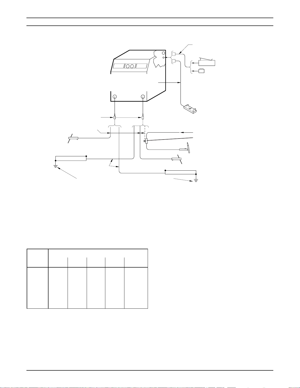
B. Stick/Scratch-Start TIG/ Arc Gouging Setup
(see Figure 2-3). These processes require
constant current (cc) type curve characteristics
for proper operation. These characteristics are
only provided when one of the remote accessories (FC-5B, TC-2B) is plugged into the J2 receptacle or when the remote HC-3B or HC-4B hand
control is connected to J2 and its process switch
is set in the CC-TIG/Stick position. Select the
desired welding mode, accessories, and polarity
as shown in figure 2-3. The output cables may be
connected for DCRP or DCSP; meaning that for
a DCRP setup, the electrode holder/torch is POS
(+) and the work is NEG (-); whereas for a
DCSP setup, the electrode holder/torch is NEG () and the work is POS (+).
Pay particular attention to high resistance in the
welding circuit; specifically, the work cable/circuit
and water-cooled torch cable. It is recommended
that the power source/wire feeder and workpiece
be placed as close together as possible to limit
resistance in the welding circuit. High resistance
in the welding circuit can cause performance
deterioration (loss of "heat" input, popping of
weld puddle, bushy arcs, etc.). Ensure the work
cable is large enough, kept as short as possible,
properly insulated, securely connected to the
workpiece, and that all connections are clean
and tightly secured. If a separate work circuit is
used (such as in mechanical fixturing, shipbuilding, robot fixturing, etc.), make sure the work
circuit is secure and presents a low resistance
path to the flow of welding current. Also, the
power cable on a water-cooled torch is normally
subject to gradual deterioration and increased
resistance due to corrosion. This leads to poor
performance as described above.
8
Regardless of your secondary welding cable setup
(DCRP or DCSP), in order to prevent electrical shock,
it is necessary that you connect the workpiece to an
approved electrical (earth) ground. The work cable
lead is not a ground lead. It is used to complete the
welding circuit between the power source and the
workpiece. This connection (at the workpiece) must
be made to a clean, exposed metal surface that is free
of paint, rust, mill scale, etc. A separate connection
is required to ground the workpiece to an approved
earth ground. The work cable should be the same
rating as the torch/electrode cable lead.
Proper operation of the power source depends to a great
extent on the use of copper output cables that are
insulated, adequately sized, in good condition and properly connected to the machine using the jack plug connectors provided. It is recommended that the output cables
be kept as short as possible, placed close together, and
be of adequate current carrying capacity. The resistance
SECTION 2 INSTALLATION
NOTE: For cc operation, either of these remote accessories (FC-5B or TC-2B) must be plugged in. However,
for MIG operations, these particular controls must be
unplugged in order to provide constant voltage.
FC-5B Foot Control
TC-2B Torch Control
HC-3B or HC-4B Hand Control
Gas Supply/Hose
TIG Torch Adaptor (Insulate from ground by taping.)
TIG Torch w/Gas Valve
NOTE: To provide cc operation with the HC-3B or HC-4B plugged in,
simply place its process switch in the CC-TIG/STICK position. Constant
voltage is provided in the CV-MIG position for "non-digital" conventional
MIG operations and in the DIGITAL-MIG (center position) for "digitalmicroprocessor" MIG operations.
(2) Male Connector for #2 thru #40 AWG
(supplied w/power source).
POWER CABLE/CONNECTION
STICK
+
J1
J2
-
WORK DCRP (-)
Connect Work to Approved Earth Ground
Figure 2-3. Stick/Scratch-Start TIG/Carbon Arc Gouging Interconnection Diagram
of the output cables and connections cause a voltage
drop which is added to the voltage of the arc. Excessive
cable resistance can reduce the maximum current output
of the power source. Refer to table 2-2 to select the
recommended output cable size.
Table 2-2. Recommended Welding Cable Sizes
Welding Total Length (Feet) of Cable in Weld Circuit*
Current 50 100 150 200 250
100
150
200
250
300
400
500
* Total cable length includes work and electrode cables. Cable size
is based on direct current, insulated copper conductors, 100% duty
cycle, and a voltage drop of 4 or less volts. The welding cable
insulation must have a voltage rating that is high enough to
withstand the open circuit voltage of the machine.
** Cam-Lock jack plug connectors will not accept smaller than No. 2
gauge cable. Also, remember that for MIG-Pulse conditions we
recommend only 4/0 cable be used due to pulse-peak currents.
6**
4**
3**
2
1
2/0
3/0
4**
3**
1
1/0
2/0
3/0
3/0
3**
1
1/0
2/0
3/0
4/0
4/0
2
1/0
2/0
3/0
4/0
4/0
--
1
2/0
3/0
4/0
4/0
--
--
STICK
WORK DCSP (+)
2.5 MIG CONTROL (J1)
INTERCONNECTION
IMPORTANT
In order to provide MIG welding (cv) operating characteristics, make sure that the J2 Remote Control
receptacle is either "vacant" (meaning no remote
accessories are plugged-in) or, if the HC-3B or HC4B hand control is plugged in, its process switch
must be set in the CV-MIG position for conventional
non-digital wire feeders or in the DIGITAL-MIG (center) position for digital-microprocessor type feeder/
controls.
Please note that all control cable functions for MIG
operations must be connected through control receptacle
J1 (19-pin amphenol) on the rear panel (see Figure 2-1).
Additionally, if remote voltage control for "non-digital"
conventional feeder/controls (only) is desired, you can
also plug in the HC-3B or HC-4B hand control accessory
to Remote Control receptacle J2 to provide this function
(see paragraph 2.6).
To make the control interconnections for various MIG
equipment controls, select from the appropriate cable
assemblies listed on table 2-3.
9

SECTION 2 INSTALLATION
Table 2-3. Control Interconnection Cables
Wire Feeders
Digimig, Digimig Dual,
Cable Lengths
6-ft (1.8 m) P/N 31829 -- P/N 30686
30-ft (9.1 m) P/N 31830 P/N 34378 P/N 30780
60-ft (18.3 m) P/N 31831 P/N 34377 P/N 30781
Mig 35 Mig 2E and Mig 4HD
and Digimatic II
2.6 ADDITIONAL REMOTE CONTROL (J2)
INTERCONNECTION
A. For non-digital conventional MIG operations. This
8-pin remote control receptacle (J2) can be used
to provide full-range remote voltage regulation
from the HC-3B or HC-4B hand control. Note that
the power source’s Panel/Remote switch must
be set to REMOTE to provide this feature. When
connected, the HC-3B's or HC-4B’s process
switch must be set to its CV-MIG position to
provide constant voltage (cv) operation and voltage regulation from its potentiometer. Also remember that the contactor switch is nonfunctional for this process — contactor control is
provided by the torch switch through receptacle
J1.
B. For Stick, TIG, or Arc Gouging operations (see
Figure 2-3). These processes require constant
current (cc) characteristics for proper operation,
and this is only provided when one of the remote
control accessories (FC-5B or TC-2B) is connected to receptacle J2, or when the HC-3B or
HC-4B hand control is connected to J2 and its
process switch is set in the CC-TIG/STICK position. Note that the power source’s Panel/Remote
switch must be set to REMOTE to provide current regulation and/or contactor control at the
welding location. When the FC-5B foot or TC-2B
torch accessory is connected, full-range current
regulation and contactor control are available
from the remote accessory.
When the HC-3B hand control is connected, the
process switch must placed in the CC-TIG/STICK
position to set up the power source for constant
current operation. Remote current regulation is
provided from the CURRENT potentiometer. The
CONTACTOR control switch must be placed in
the ON position to provide welding power to the
torch/electrode.
If the HC-4B hand control is connected, you must
place its Process switch in the CC position to set
up the power source for constant current operation. Remote current regulation (up to full range)
is provided from the CURRENT control potentiometer. The CONTACTOR control switch must
be placed in the ON position to provide welding
output current to the torch/electrode. The HC-4B
also incorporates two additional control features;
a TIG/Stick selector and an Arc Force potentiometer that functionally operates in the STICK mode.
The TIG and Stick modes provide the same cc
type volt-ampere curve characteristic; however,
the slope of the STICK curves can be further
adjusted by regulating the Arc Force control pot.
The lower Arc Force settings provide less short
circuit current and a softer, more stable arc;
whereas the high settings provide more short
circuit current and a forceful, more penetrating
arc.
10

SECTION 3 OPERATION
3.1 INTRODUCTION
This section is intended to familiarize personnel with the
operational procedures applicable to the SVI 450i cvcc
power source. Information contained in this section should
be read carefully before operation of the power source.
Never, under any circumstances, operate the power
source with the cover or side panels removed. In
addition to the safety hazard, improper cooling may
cause damage to internal components. Also make
sure you are adequately protected before welding.
Welding helmet, gloves, safety glasses, and ear protection should always be worn.
3.2 DUTY CYCLE
Duty cycle is defined as the ratio of load time to total time.
Standard current ratings are based on a 10-minute cycle.
The SVI 450i cvcc power source has a 60% duty cycle
rating which allows 450 amperes @ 38 V dc (see Figure
3-1). The 60% duty cycle rating means that the 450ampere rated load can be applied for a total of 6 minutes
and shut off for a total of 4 minutes in a 10-minute period.
If the welding current is decreased, the duty cycle can be
increased. Conversely, if the welding current is increased,
the duty cycle must be decreased.
Important Digimig/Digimatic Operational Note
All ESAB microprocessor-type wire feeder/controls
are designed to provide good arc starts with power
supplies that utilize a FLAT-SLOPE volt-ampere curve
characteristic. Since this power supply also allows
you to select a MEDIUM or STEEP slope characteristic, you may have to readjust the microprocessor’s
factory-set "starting" characteristics to provide the
best arc-starts possible using the "steeper" voltampere curves. The procedures required to recalibrate
the microprocessor "hot-start" characteristics are
provided in all of the appropriate Digimig/Digimatic
instruction booklets.
3.4 POWER SOURCE WELDING
CONTROLS
A. On-Off Line Switch (LS). Placed in the ON
position, this switch (located on the rear panel)
provides primary input power to start the cooling
fan motor and energize the secondary control
circuitry. Power light (PL1) on the front panel
should illuminate.
B. Digital Voltmeter/Ammeter (DPM) and Selec-
tor (SW2). This instrument provides direct digital
reading of open-circuit or welding, or welding
current depending on the position of the VOLT/
AMP selector switch.
C. Troubleshooting Lights.
3.3 VOLT-AMPERE (SLOPE)
CHARACTERISTICS
The curves shown in figure 3-2 represent the volt-ampere
static characteristics for the power supply in the MIG (cv)
and TIG (cc) modes. The slant of these curves is referred
to as the ‘slope’ and is generally defined as the ‘voltage
drop per 100 amperes of current rise.’ These curves show
the output voltage available at any given output current
between the minimum and maximum settings of the
voltage/current control. Typical curves are shown for
other settings between the minimum and maximum curves.
Because the volt-ampere slope is fixed, it is possible to
select optimum welding conditions by approximating the
open-circuit voltage required for a particular load current.
If you require greater slope (shown as dotted curves at
maximum setting) for your MIG welding applications, you
may change the slope switch position located on the front
panel. The static volt-ampere slope is not affected by the
inductor rheostat setting. For welding aluminum or stainless steel, the steeper slope settings are recommended.
1. Temperature (PL2). This will light if components in the power source overheat. The contactor
will then deenergize. Allow the power source to
cool with the line switch in the ON position (the
fan will help cool the power source) before continuing welding operations when light goes off.
2. Fault (PL3). This light functions as a visual
detector for two specific fault conditions:
overcurrent or over/undervoltage indication. In
either case, if a fault is detected in the inverter
bridge, the contactor will deenergize and the
power source will stop welding. If an overcurrent
condition caused the problem, the fault light will
energize and remain "steady-on." Do not attempt
to restart welding (refer to Section 5). If an over
or undervoltage condition occurs, the fault light
will flash. Since this can often be caused by a
transient, retry the torch switch to resume welding. If tripping continues, stop and refer to section
5.
11
SECTION 3 OPERATION
D. Voltage Control Potentiometer (VCP). This
control sets and regulates the desired amount of
welding voltage required for your operation. The
panel-faced dial surrounding the control knob
provides a convenient reference for resetting
prior welding conditions. Note that the Panel/
Remote switch must be in the PANEL position
when this control (VCP) is used.
E. Panel/Remote Control Switch (SW1). This
switch determines the location from which welding voltage will be regulated. In the PANEL position, full-range voltage is controlled by setting the
Voltage Control Potentiometer (VCP) on the
power supply — if desired, this position may be
used for non-digital (conventional) wire feeder
voltage control. In the REMOTE position, full
range voltage control is regulated either from the
J1 receptacle for mechanized controls or digitalmicroprocessor type (Digimig/Digimatic) feeder
controls, or from the J2 receptacle for non-digital
(conventional) feeder controls using the remote
accessory hand or torch controls.
The REMOTE position is also required to provide
full range "current" control from the J2 receptacle
using the remote accessory hand, foot or torch
controls for the Stick/TIG/Gouging processes.
F. Slope Control Switch (SW3). This 3-position
switch sets the slope of the volt-ampere curve
characteristic in the MIG (cv) mode — this control
feature is bypassed in the TIG/Stick (cc) mode.
Slope positions (top-to-bottom) are as shown in
table 3-1.
to minimum for all pulse and standard spray arc
welding applications.
H. Digital MIG Control Receptacle (J1). This 19-
pin remote control receptacle receives a mating
connector from the MIG/Digimig wire feeder or
other mechanized MIG controls (see Figure
2-1).
I. TIG/Stick Control Receptacle (J2). This 8-pin
remote control receptacle, located on the rear
panel, receives a mating connector from the
remote control accessories (see Figure 2-3).
J. Reset Circuit Breaker (CB). A 10-ampere cir-
cuit breaker (on the rear panel) provides protection to the 115-volt control circuit. If an overload
occurs, the breaker will trip and suspend all
operation. To restore service, depress the breaker
button to reset the circuit.
K. Auxiliary 115 Volt Receptacle (J3). This recep-
tacle supplies 5 amperes of 115-volt power for
auxiliary equipment.
L. Welding Output Receptacles. Two output re-
ceptacles are located on the front panel — one
negative (-) and one positive (+). Refer to figures
2-1 and 2-3.
3.5 SEQUENCE OF OPERATION
Table 3-1. Slope Positions
Switch Position Process/Material Slope
MEDIUM
STEEP
FLAT
Short Arc/MS/AL
Short Arc/MS,AL,SS
Spray Arc
3 V/100 A
6 V/100 A
1 V/100 A
G. Inductance Control Potentiometer (ICP). This
control allows the operator to set and regulate the
desired amount of inductance required for standard MIG short arc welding operations. Variable
control allows the operator to fine tune the inductance needed to make the weld puddle more fluid
and minimize the weld spatter produced during
MIG short arc applications. When short arc
welding stainless steel, high values of inductance should be used with A1025 helium rich
shielding gas. This potentiometer should be set
12
Never, under any circumstances, operate the power
source with the cover or side panels removed. In
addition to the safety hazard, improper cooling may
cause damage to internal components. Also make
sure you are adequately protected before welding.
Welding helmet, gloves, safety glasses, and ear protection should always be worn.
A. MIG Welding
1. Make all secondary output connections to the
power source output receptacles as described in
section 2 (see Figure 2-2) and as shown in the
appropriate wire feeder and/or control instruction
booklets.
2. Make the necessary control connections to receptacle J1 as described in section 2 (see Figure
2-2) and J2, if necessary. Make sure that FC-5B

SECTION 3 OPERATION
or TC-2B is unplugged from J2, or if HC-3B or
HC-4B is plugged in, the process switch is in the
DIGITAL-MIG (center) position.
3. After the primary input connections have been
made in accordance with section 2, close the
main wall disconnect switch or circuit breaker.
4. Place the power source ON-OFF line switch (on
rear panel) to the ON position. This will start the
cooling fan and apply power to the control circuitry as indicated by the illuminated POWER
pilot light on the front panel.
5. Set the Voltage Control Potentiometer (VCP) for
the approximate desired welding voltage depending on the position of the Panel-Remote
voltage control switch (see step 6).
6. Set the Panel-Remote switch (SW-1) to the desired position from which full-range welding voltage will be regulated — PANEL position for
operation from the power supply front panel
(typical for non-digital conventional MIG feeders), or REMOTE position for operation from
remote wire feeders/controls for digital-microprocessor MIG equipment, or for conventional
MIG using the HC-3B or HC-4B hand control.
B. Stick/Scratch-Start TIG Welding
1. Depending on the process being used, make all
secondary output connections to the power source
output receptacles (see Figure 2-3).
2. Connect appropriate control accessories to receptacle J2 (see Figure 2-3).
3. After the primary input connections have been
made, close the main wall disconnect switch
or circuit breaker.
4. Place the power source ON-OFF line switch (on
the rear panel) to the ON position. This will start
the cooling fan and apply power to the control
circuitry as indicated by the illuminated POWER
pilot light on the front panel.
Ensure the contactor control switch on the TC-2B
torch control, HC-3B or HC-4B hand control, or the
Stick control pendant is in its OFF position (until
you're ready to weld); otherwise, the electrode will be
energized and may cause a short or electrical shock.
7. Set the variable inductance control (on the front
panel) to provide the amount of inductance desired for MIG short arc welding. For MIG spray
arc and pulsed MIG welding, this control
should be set at MINIMUM.
8. Set the Slope Control Switch (SW3) to provide
the desired slope characteristic (FLAT, MEDIUM
or STEEP) required for your MIG process/material and feeder/control.
9. For remaining wire feeder or control operations,
refer to the appropriate instruction booklet supplied for your particular system.
Operational Note For Digimig Series Wire Feeders
Due to the high open-circuit voltage of this power
supply, it is possible that some Digimig controls may
"abort" if the torch switch is energized for 2 seconds
without striking a welding arc. This will most likely
occur if you use the torch switch to thread new wire
in the torch liner or for wire inching operations. (It will
not occur if you use the recommended cold wire
inching controls, provided on the feeder, for these
functions.) If an "abort" does occur, simply "reset"
the control as described in the appropriate wire
feeder instruction booklet.
5. The variable inductance control need not be set
for these processes because it is isolated from
this circuit.
6. Full range current control is provided and regulated by the potentiometer on the selected remote controls. If the HC-3B or HC-4B is connected, ensure it is set for CC-TIG/STICK operation.
7. To establish the welding arc, position the torch/
electrode near the workpiece. Close the remote
torch/foot control or turn the pendant on. This will
energize the solid-state contactor and provide
welding power to the torch/electrode. Commence welding by touch or scratch starting.
8. If necessary, readjust the remote current potentiometer until the exact condition desired is obtained.
13

SECTION 3 OPERATION
80
70
60
50
40
VOLTS
30
20
10
CV MODE
MIN
0
0
100 200 300 400 500 600
AMPERES
80
70
60
50
40
VOLTS DC
30
20
MINIMUM CURRENT
10
0
MAX
STICK CC MODE
MIN. AF
AMPERES DC
MAX. AF
80
70
60
50
40
VOLTS DC
30
20
10
0
0700
MIN
200100
ARC FORCE RANGE
@ A MEDIUM
CURRENT SETTING
AF=ARC FORCE SETTING
MAXIMUM CURRENT
TIG CC MODE
AMPERES DC
MAX
600500400300
700
7006005004003002001000
120
110
100
90
80
70
DUTY CYCLE BASED ON
60
10-MINUTE PERIOD AND
MAX. AMBIENT OF 40
50
% DUTY CYCLE
40
30
20
10
0
Figure 3-1. Volt-Ampere Curves
O
C.
MAX SHORT CIRCUIT
2001000
400300
OUTPUT CURRENT
Figure 3-2. Duty Cycle Rating Chart
DUTY CYCLE-3ø
DUTY CYCLE-1ø
500
600
14

SECTION 4 MAINTENANCE
4.1 GENERAL
If the power source does not operate properly, stop work
immediately and investigate the cause of the malfunction.
Maintenance work must be performed by an experienced
person, and electrical work by a trained electrician. Do not
permit untrained persons to inspect, clean, or repair this
equipment. Use only recommended replacement parts.
Electric shock can kill! Ensure the wall disconnect
switch or circuit breaker is open before attempting
any inspection or work on the inside of the power
source. Always wear safety goggles with side shields
when blowing out the power source with low pressure air.
4.2 CLEANING
Since there are no moving parts (other than the fan) in the
power source, maintenance consists mainly of keeping
the interior of the cabinet clean. Periodically, remove the
cover from the cabinet and, wearing proper eye protection, blow accumulated dust and dirt from the air passages and the interior components using clean low pressure air. It is imperative that the air passages to the
interior of the unit be kept free of dirt accumulation to
ensure adequate circulation of cooling air; especially,
over the rectifier bridge plates. The length of time between cleaning will depend on the location of the unit and
the amount of dust in the atmosphere.
4.3 LUBRICATION
Fan motors with oil tubes located on the side of the motor
require lubrication after 1 year of service. Motors without
oil tubes are permanently lubricated for life and should not
require any attention.
15
SECTION 5 TROUBLESHOOTING
5.1 TROUBLESHOOTING
Electric shock can kill! Ensure all primary power to
the power source has been externally disconnected.
Open wall disconnect switch or circuit breaker before attempting inspection of work inside of the
power source.
Capacitors can explode causing personal injury. To
avoid injury, carefully read and do the following:
The subject warning concerns the four power filtering capacitors mounted behind Power Board No. 1
and No. 2. (For location, see figure 6-3.)
This potential hazard exists when the side panels are removed
and power is ON. This should only occur when troubleshooting
the power source.
Safe troubleshooting practice requires a systematic procedure as
follows:
1. Disconnect primary input power to power source.
2. Remove panels and perform visual inspection for obvious problems; loose wiring and plug connections, damaged or discolored components, etc.
3. Perform resistance checks described in the following
tables.
4. With input power deenergized and side panels removed, locate the Input Bridge Module (IBR) (see Figures 5-1 and 6-5). Using the existing wiring diagram
(Figure 5-5), disconnect and tape the large gray leads
attached to terminals IBR (+) and IBR (-). This will
prevent high voltage input to power boards No. 1 and
No. 2, eliminating the potential hazard while performing
the low voltage checks in step 5.
7. With the side panels in place, reapply input power to the
power source and perform high voltage checks (desig-
nated by ) listed in the following tables.
A. Wire Feeder or Control
If it is determined that the wire feeder is operating
improperly, refer to the troubleshooting information
located in the instruction booklet.
B. Power Source
If the power source is operating improperly, the
following troubleshooting information may be used to
locate the source of the problem.
Check the problem using the following troubleshooting guide (Figure 5-1). The potential problems are
listed in "most probable" order, and the remedy may
be quite simple. If the cause cannot be located
quickly, open the power source and perform a simple
visual inspection of all components and wiring. Check
for secure terminal and plug connections, loose or
burned wiring or components, bulged or leaking
capacitors, or any other sign of damage or discoloration. Always follow this general rule — Do not replace
a printed circuit (PC) board until you have made all of
the checks listed in the following guide. Always put
the power switch in its OFF position before removing
or installing a PC board. Take great care not to grasp
or pull on components when removing a PC board
and always place a removed board on a static-free
surface. If a PC board is found to be the problem,
check with your ESAB supplier for a replacement.
Provide the distributor with the part number of the
board, as well as the serial number of the power
source. Do not attempt to repair the board your-
self. Warranty on a PC board will be null and void
if repaired by customer or any unauthorized repair shop.
NOTE
High voltage checks, listed in the following tables, must be
performed with the side panels installed and IBR leads connected. To distinguish the high voltage checks (from low voltage)
we have indicated these readings with the symbol. H.V.
5. Apply input power to the power source, and perform the
low voltage checks described in the following tables.
6. After the low voltage checks are completed, disconnect
input power to power source and reconnect IBR (+) and
(-) leads to module, and reinstall the unit's side panels.
16

SECTION 5 TROUBLESHOOTING
Table 5-1. Troubleshooting Guide (Sheet 1 of 2)
PROBLEM POSSIBLE CAUSE CIRCUIT CHECKS
Unit inoperative - fan
does not run
Blows input line fuses Defective Input Bridge (IBR)
No open circuit voltage 115 V ac circuit breaker tripped
Incorrect primary condition or blown line
fuse
Incorrect linkages on voltage changeover
board
Defective Line Switch (LS)
Incorrect linkages on voltage changeover
board
Defective PB1/PB2
MIG mode operation
1. Stick pendant/control plugged into J2
2. No contactor signal from wire
feeder/control
STICK mode operation
1. No contactor signal from
pendant/control
Check incoming power to unit
Check links on voltage changeover
terminal board
Perform continuity check on Line Switch
See IBR Troubleshooting
Check links on voltage changeover
terminal board
See PB1/PB2 Troubleshooting
Check circuit breaker and reset if tripped
Check J2 and disconnect pendant/foot
control
Check MIG contactor signal - see ICB
troubleshooting
Check STICK contactor signal - see ICB
troubleshooting
No open circuit voltage Defective SCR1/R1
Missing bias voltage to Inverter Control
Board (ICB)
False thermal indication to ICB
Defective ICB
Excessive open circuit
voltage
Thermal overload Exceeding duty cycle rating
Flashing fault indicator Input voltage not within +15% and -10% of
Defective resistor/capacitor across Output
Bridge (OBR)
Exceeding max. rated ambient temperature
rated requirements
Excessive line impedance
Defective Inverter Control Board (ICB)
See SCR1 troubleshooting
See ICB troubleshooting
See ICB troubleshooting
Replace ICB
Check components R4, C7, R5, C8
See duty cycle rating chart
40 °C (104 °F)
Check incoming voltage to unit - all three
phases
Check voltage TB-1 (+) to TB-4(-). See
IBR troubleshooting
Replace ICB
17

SECTION 5 TROUBLESHOOTING
Table 5-1. Troubleshooting Guide (Sheet 2 of 2)
PROBLEM POSSIBLE CAUSE CIRCUIT CHECKS
Flashing fault indicator Input voltage not within +15% and -10% of
rated requirements
Excessive line impedance
Defective Inverter Control Board (ICB)
Continuous fault
indicator
Low welding output Single-phase operation
Defective PB1/PB2
Defective Output Bridge Module (OBR1-4)
CT1/CT2 lead open
Missing shunt signal to Inverter Control
Board (ICB)
Defective ICB
Incorrect slope setting for application
Check incoming voltage to unit - all three
phases
Check voltage TB-1 (+) to TB-4(-). See
IBR troubleshooting
Replace ICB
See PB1/PB2 troubleshooting
See OBR troubleshooting
Disconnect P4 connector to inverter
control and make continuity check P4-1 to
P4-2/P4-4 to P4-5
See ICB troubleshooting
Replace ICB
Check incoming power to unit - all three
phases
Reference VA curves and change slope
according to required output (volts and
amps)
Excessive welding
output
Volt/Amp Meter blank
or reads incorrect
Excessive welding cable length
Welding cable size too small
High resistance torch power cable
Inverter Control Board (ICB) calibration
Defective ICB
Missing arc voltage feedback to Inverter
Control Board (ICB)
ICB calibration
Defective ICB
Missing +5 V at Inverter Control Board
(ICB)
Shunt calibration
Recommend max cable length (work and
torch) of 100 ft
Recommend 4/0 cable for MIG
applications
Replace torch if defective/use torch with
voltage pickup lead
See ICB troubleshooting
Replace ICB
See ICB troubleshooting
See ICB troubleshooting
See ICB troubleshooting
See ICB troubleshooting
Check millivolt drop across shunt - should
read 10±0.3 mV per 100 amps output
18
Defective ICB
Defective meter
Replace ICB
Replace meter

SECTION 5 TROUBLESHOOTING
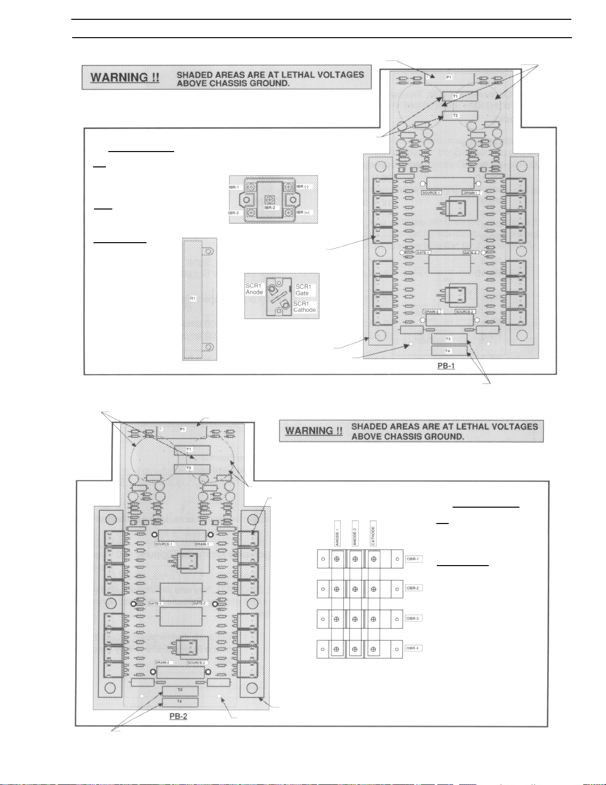
C. Power Boards, PB1/PB2, Troubleshooting (See
Figures 5-1 and 5-2)
Make sure input power is disconnected (OFF) and
voltage between T1 and T2 is zero.
Resistance Checks
(+)Probe (-)Probe Measurement
Drain-1 Source-1 5k ohms nominal*
Source-1 Drain-1 diode forward drop**
Gate-1 Source-1 1k ohms nominal*
Drain-2 Source-2 5k ohms nominal*
Source-2 Drain-2 diode forward drop**
Gate-2 Source-2 1k ohms nominal*
* Using meter high impedance diode scale.
** Using meter low impedance diode scale.
Voltage Checks (T.S. deenergized)
(+) Probe (-) Probe Measurement
TB-1(+) TB-3(-) 324 V dc
TB-2(+) TB-4(-) 325 V dc
Gate-1 Source-1 -12 V dc
Gate-2 Source-2 -12 V dc
P1-1 P1-3 24 V ac
P1-1 P1-2 12 V ac
P1-2 P1-3 12 V ac
P1-8 P1-10 24 V ac
P1-8 P1-9 12 V ac
P1-9 P1-10 12 V ac
D. Input Bridge, IBR, Troubleshooting
(See Figure 5-1)
Resistance Checks
(+) Probe (-) Probe Measurement
IBR-1,2,3 IBR (+) diode forward drop**
IBR (+) IBR-1,2,3 open*
IBR (-) IBR-1,2,3 diode forward drop**
IBR-1,2,3 IBR (-) open *
Voltage Checks
*Using meter high impedance diode scale.
**Using meter low impedance diode scale.
TB-1(+) 375-290 V dc @ 230 V ac
(+15%/-10%)
TB-4(-) 750-580 V dc @ 460 V ac
(+15%/-10%)
E. Output Bridge, OBR, Troubleshooting
(See Figure 5-2)
Resistance Checks
(+) Probe (-) Probe Measurement
Anode-1 Cathode diode forward drop**
Anode-2 Cathode diode forward drop**
Cathode Anode-1 open*
Cathode Anode-2 open*
*Using meter high impedance diode scale.
**Using meter low impedance diode scale.
NOTE
If any of the above readings are incorrect, remove the
busbars and check modules OBR1-4 individually. Replace modules which are defective.
19

SECTION 5 TROUBLESHOOTING
F. SCR1 Troubleshooting (See Figure 5-1)
Resistance Checks
SCR1-A SCR1-K 5 ohms If reads open, then replace R1
If reads short, then replace SCR-1
SCR1-G SCR1-K diode forward drop (low impedance using diode scale)
Gate Lead from Inverter Control should be disconnected
Voltage Checks
SCR1-G SCR1-K 0 V dc Torch switch deenergized
0.6 V dc Torch switch energized - if missing, check Inverter Control
20
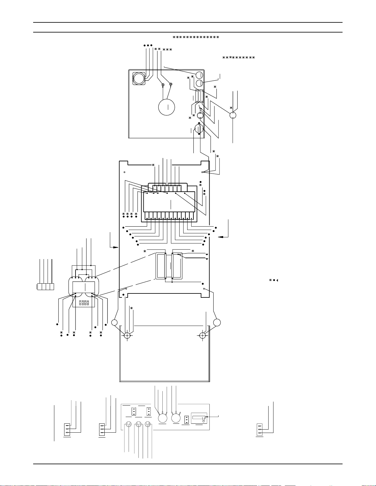
SECTION 5 TROUBLESHOOTING
P1 CONTROL PLUS
* To replace Power Boards (PB-1 & PB-2), disconnect cables form T1-T4, disconnect control
plug P1, loosen capacitor mounting brackets behind board, remove and retain transistor mounting
screws and two mounting screws at bottom of board. NEVER, UNDER ANY CIRCUMSTANCES,
REMOVE OR LOOSEN ISOBARS ATTACHED TO HEAT SINK!
T1, T2, POWER CABLE CONNECTIONS*
Torque Specifications
IBR
Case to Heatsink - 40 lb. in.
Terminals - 25 lb. in.
SCR1
Case to Heatsink - 25 lb. in.
Terminals - 25 lb. in.
PA1 - Transistors
Case to Isobar - 10 lb. in.
(TYP.) TRANSISTOR MOUNTING -
SCREW (TOTAL-16)
When replacing the
components, make
sure mounting surfaces
are clean. Coat surfaces
with Dow-Corning #340
silicon heat sink
compound or equivalent.
All hardware must be
torqued to above
specifications
ISOBAR, TYPICAL EACH SIDE*
P.C. BOARD MOUNTING
SCREW, TYPICAL EACH SIDE*
Figure 5-1. Left Side Power/Control Components (PB-1, SCR1, IBR, R1)
CAPACITOR MOUNTING BRACKETS
(BEHIND BOARD)
P1 CONTROL PLUS
CAPACITOR MOUNTING BRACKETS
(BEHIND BOARD)
T3, T4, POWER CABLE CONNECTIONS*
T3, T4, POWER CABLE CONNECTIONS*
Figure 5-2. Right Side Power/Control Components (PB-2, OBR-1,2,3,4)
* To replace Power Boards (PB-1 & PB-2), disconnect cables form T1-T4, disconnect control
plug P1, loosen capacitor mounting brackets behind board, remove and retain transistor mounting
screws and two mounting screws at bottom of board. NEVER, UNDER ANY CIRCUMSTANCES,
REMOVE OR LOOSEN ISOBARS ATTACHED TO HEAT SINK!
T1, T2, POWER CABLE CONNECTIONS*
(TYP.) TRANSISTOR MOUNTING -
SCREW (TOTAL-16)
Torque Specifications
IBR
Case to Heatsink - 40 lb. in.
Terminals - 20 lb. in.
PA2 - Transistors
Case to Isobar - 10 lb. in.
When replacing the
components, make
sure mounting surfaces
are clean. Coat surfaces
with Dow-Corning #340
silicon heat sink
compound or equivalent.
All hardware must be
torqued to above
specifications
ISOBAR, TYPICAL EACH SIDE*
P.C. BOARD MOUNTING SCREW, TYPICAL EACH SIDE*
21

SECTION 5 TROUBLESHOOTING
G. Inverter Control Board, ICB, Troubleshooting (See Figure 5-3)
Voltage Checks
(+) Probe (-) Probe Measurements
P5-8 P5-9 18 V ac AC Bias
P5-8 P5-10 36 V ac AC Bias
P5-6 P2-9 12 V dc DC Bias
P5-5 P2-9 -12 V dc DC Bias
P5-3 P1-6 5 V dc Digital Meter Bias
P5-1 P2-9 10 V dc DC Bias
P4-7 P4-8 115 V ac MIG Contactor Signal
P4-9 P4-10 24 V ac Stick Contactor Signal
P2-10 P3-1 72 V dc Arc Voltage - open circuit
P1-1 P1-2 10 ±0.3 mV Shunt Signal/100 amps
P1-4 P1-5 10 ±0.3 mV Meter Signal/100 amps
P3-3 P2-2 12 V dc MIG Mode Select
0 V dc Stick Mode Select
P3-9 P3-10 0 V dc Thermal-Normal
12 V dc Thermal-Overload
P2-5 P2-2 0 V dc Steep Slope
5 V dc Medium Slope
12 V dc Flat Slope
22

SECTION 5 TROUBLESHOOTING
TP1
TP2
Figure 5-3. Inverter Control Board (ICB) (Top View Layout)
23

SECTION 5 TROUBLESHOOTING
PB2 - POWER BOARD #2
PB1 - POWER BOARD #1
LS - LINE SWITCH
IBR - INPUT BRIDGE MODULE
5
3
4
1
2
12
3
J3
CTR2
PL1
H2
TB-5
B
WHITE
115 VAC
X4
X3
2
H2
2
X2
H3
TB-7
6
T1-4
T1-2
TB-8
H4
WELD
K2
X6
X5
9
T1-3
P4-7
X3
13
D
C
CONTACTOR
SAFETY GROUND
2
TS2
1
2
1
TS1
P3-9
P4-8
P5-8
P5-9
X4
H5
1
TB-10
FM
14
U
T
B
K2
A
2
CB1
10A
1
X18
P3-10
ICB
INVERTER
P5-10
X5
H6
2
TB-6
11
J1
A
BLACK
115 VAC
X2
L1
X1
1
T1-1
H1
2
10A
1
CB2
1
T1-5
X1
230/460/3 PH 60 HZ W/EQUIP GND
CTR1
H1
TB-9
-
1
2
6
4
LS
3
2
5
1
3
IBR
C11
1000V
0.22UF
+
P6-5
G
K
A
SCR1
SH - SHUNT
CTR1 - CONTROL TRANSFORMER #1
CT1 - CURRENT TRANSFORMER #1
MTR - MAIN TRANSFORMER
CT2 - CURRENT TRANSFORMER #2
6
7
CB2 - CIRCUIT BREAKER
IND - INDUCTOR
OBR - OUTPUT BRIDGE MODULE
9
8
10
11
15
J
H
F
V
E
G
-12 VDC
+12 VDC
COMMON
CONTROL (MIG)
CTR1
X19
2
PL2
1
P3-6
P5-5
P5-6
P2-9
BOARD
CONTROL
P6-4
P6-6
P6-5
SCR-G
TB-1
TB-4
P6-6
SCR-K
R7
20K, 12W
TB-2
460V
TB-3
R6
20K, 12W
R10
PB1-P1-7
T2
(-)
(+)
T1
CTR1
T2
(-)
(+)
T1
Ω
100
1/2W
P1-1
X12
X6
P1-1
P6-3
PB1-P1-6
D
P1-2
X13
X7
P1-2
D
G
L1 - COMMON MODE CHOKE
CTR2 - CONTROL TRANSFORMER #2
J3 - 115V RECEPTACLE
PL1 - POWER LIGHT
12
TS1 - THERMAL SWITCH - POWER ASSEMBLY
J1 - DIGIMIG INTER-CONNECT RECEPTACLE
13
14
16
L
M
N
P1-10
P6-7
P1-4
G
S
P1-4
K
POS-OTB
P3-2
P6-8
P1-5
P1-7
P1-8
P1-3
X15
X14
X8
X9
P1-3
P1-8
PB1
S
P1-5
TORCH
P2-10
P6-10
G
S
PB2
P1-9
X16
X10
P1-9
G
P1-6
P1-7
WORK
P3-1
P6-9
X11
S
SH +
P5-2
P6-1
R9
PB1-P1-4
P1-6
D
P1-10
X17
P1-10
D
P
SH -
P5-6
FLAT
1
P5-4
Ω
1/2W
100
T4
C6
R3
T3
T4
R2
T3
PL2 - THERMAL OVERLOAD LIGHT
FM - FAN MOTOR
ICB - INVERTER CONTROL BOARD
CB1 - CIRCUIT BREAKER
TS2 - THERMAL SWITCH - INDUCTOR
K
G
COMMON
P5-3
STEEP
MED
3
2
SW3
P2-5
P6-2
P4-4
T2-3
T2-4
PB1-P1-5
X2
X1
.05UF
CT2
10,
100W
P4-1
T2-1
T2-2
X2
X1
C5
.05UF
CT1
10,
100W
K2 - RELAY
F
E
+10 VDC
CONTROL (STICK)
P2-2
P5-1
P2-1
P4-1
P4-5
T2-1
H2
"B"
H1
P4-2
H2
"A"
H1
MTR
15
D
CP/CC SELECT
P4-2
T2-2
X3
X2
X1
J2 - WIRE FEEDER RECEPTACLE
16
A
CONTACTOR
P3-3
PL3 - VOLTAGE/FAULT LIGHT
DPM - DIGITAL PANEL METER
ICP - INDUCTANCE CONTROL POTENTIOMETER
VCP - VOLTAGE CONTROL POTENTIOMETER
19
18
17
17
P4-9
P3-7
H
B
CONTACTOR
SAFETY GROUND
T1-7
X3
X1
T1-6
P4-10
1
2
PL3
R5
5.25W
C8
.05UF
C7
.05UF
R4
5.25W
18
J
P2-2
CTR2
ARC DETECTOR
ARC DETECTOR
P3-4
P3-5
P2-3
P3-8
2
3
1
1
2
3
3
OBR2
OBR1
C
T1-8
CW
10K
REMOTE
3
2
1
ICP
2
SW1
P2-4
OBR3
P2-8
J2
+10V
PANEL
1
P1-3
1
2
3
P1-7
P5-1
3
VCP
P1-2
1
3
OBR4
19
P2-2
2
1
10K
SW2
1
2
VOLTS
AMPS
C12
P1-1
0.22UF @ 16V
P1-9
P1-8
P5-3
P1-6
P1-5
P1-4
SH
-
J1-N
J1-P
2
IND
X2
X1
ROH
10
RFH
D3 V (+)
TST
IN LO
IN HI
DPM
9
RFL
8
COM
5
.01UF
C10
NEG
11
1
4
6
7
+
Figure 5-4. SVI 450i Schematic Diagram - 230/460 V, 3 Phase, 60 Hz
C9
.01UF
POS
31951
D-
24
50W
R1
5,
2
1
3
ICB-P6-4
ICB-P6-2
ICB-P6-3
ICB-P6-1
5
4
6
7
8
9
10
SECTION 5 TROUBLESHOOTING
GRN
ORN
YEL
WHT
BRN
BLK
RED
GRY
GRY
GRY
TB-6
TB-8
L1-X2
A
IBR-1
IBR-2
IBR-3
BLK
BLK
2
1
3
4
LS
6
5
1
P5-10
CB1-1
ICB
BLU
TB-9
PB1
P1-3
P1-8
J1-V
BRN
YEL
BLU
X5
X19
X18
H2
H1
H3
X9
X10
X7
X8
X6
BLK
PB1
RED
PB1
BLK
PB1
BRN
P1-9
YEL
PB1
PB1
BRN
P1-10
MTR X2
X1
X2
"A" COIL
GND 1
GRY
ORN
BRN
TB-7
TB-5
TB-8
P1-1
P1-2
VIEW "A"
OBR-BUS #1
OBR-BUS #2
GRY
GRY
IND-BX1
GRY
PB1-T3
WHT
C5-2
IND-AX1
"A"
T2
GRY
PB1-T4
X2
X3
X1
C9
GND 2
ICB-P2-10 GRY
IND AX2. BX2 GRY
J2-K GRY
"B"
MTR
H1
H1
H2
H2
2
4
3
1
GRY
PB2-T4
WHT
C6-2
GRY
PB2-T3
WHT
R3-1
BLU
GRY
YEL
ORN
P4-5
P4-2
P4-4
P4-1
ICB
ICB
ICB
ICB
2
1
3
4
T2
WHT
R2-1
P5-9
ICB
RED
L1-X4
2
FM
X4
H4
P2-9
P3-2
P5-6
P5-5
P1-10
GND4
ICB
ICB
ICB
T1-8
L1-X6
ICB
ICB
D
G
E
F
T1-5
BLK
X1
X14
1
2
TS2
"B" COIL
GRY
K
H
J
J1-B
J1-A
L1
T1-2
T1-1
CB2
J3
T1-1
BLK
H6
X17
X15
X16
BLU
GRY
ORN
P1-2
P1-1
GRY
MTR X2
WHT
WHT
B
C
P5-8
T1-4
ICB
WHT
ORN
X2
X3
H5
CTR1
X12
X13
X11
X1
IND
X2
GRY
BLU
(TP)
RED
P2-10
P3-1
SH+
ICB
ICB
N
L
M
J1
J2
X2
X4
X6
X1
X3
X5
2
1
3
2
1
GND 4
TB-6
VIO
TB-10
YEL
BLU
P1-9
WHT
P1-8
PB2
P1-3
PB2
PB2
TS1-2
PL2-2
POS OUTPUT
SH (+)
(TP)
BLK
SHP
T1-3
P1-10
PB2
GND 3
T1-2
WHT
GRY
CB1-2
T
T1-1
BLK
PB2
PB2
BRN
K2-B
U
J2-H
GRN
J1-C
YEL
CTR1-X19
V
J2
T1-5
BLK
J1-D
GRN
C10
BLK
P4-9
ICB
A
VIEW "B"
RED
T1-7
B
CB1
BRN
VIO
T1-8
P3-3
ICB
C
D
GRY
J1-T
2
1
BRN
CTR1-X18
GRY
K2-A
YEL
P5-1
ICB
E
GRN
BLU
ORN
ORN
GRY
P2-1
P2-2
P2-2
GND4
ICB
ICB
ICB
POS-OTB
H
F
J
G
K
INDICATES CONNECTOR USING IN-LINE
INDICATES SELF LEADS
INDICATES 600V WIRE
TWISTED PAIR
QUICK DISCONNECT
SHIELDED PAIR
TP
SP
31952
D-
BRN ICB P5-3
GRY ICB P2-5
3
2
1
SW3
WHT ICB P5-6
BRN T1-8
3
2
1
SW1
VIO ICB P2-8
GRY VCP-2
POS
(+)
SW3
PL1
2
BLK T1-5
WHT T1-4
PL2
212
1
WHT TS2-2
BLU ICB P3-6 (+)
WHT ICB P3-10
P2-2
SW2-2
ICB
SW1
ORN
ORN
PL3
1
BRN ICB P3-7 (+)
ORN ICB P3-8
1
SW1-1
GRY
2
VCP
P5-1
NEG
(-)
Figure 5-5. SVI 450i Wiring Diagram - 230/460 V, 3 Phase, 60 Hz (Sheet 1 of 2)
P2-4
P2-3
ICB
ICB
ICB
RED
BLK
YEL
1
4
2
1
3
13
3
ICP
SW2
C 12
DPM
P1-9
ICB
GRY
1
P1-6
P1-4
P1-5
ICB
ICB
ICB P1-8
DPM-5
DPM-8
DPM-10
ICB
DPM-9
CLR
SHLD
BLK
3
4
5
2
ORN
BLK
BLK
BLK
BLK
7
11
8
12
9
6
P1
13
10
ORN VCP-1
WHT ICB P1-7
3
2
1
SW2
25

SECTION 5 TROUBLESHOOTING
BLU
J1-H
WHT
CTR1-X2
T1-7
BLU
X3
2
H2
WHT
R5-1
PB2
BLK
J1-P
(TP)
PB1
WHT
PL1-2
4
WHT
P4-7
ICB
T1-2
BLK
(-)
BLK
(SP)
BLK
CB2-1
BLK
CTR1-X1
1
1
2
3
OBR2
P1-2
ICB
5
BLK
PL1-1
SH
BLU
CTR2-X1
6
BRN
P4-10
ICB
TS1
1
2
3
OBR3
2
1
CTR2-X3
7
RED
J2-B
T
1
GRY
P3-9
ICB
CLR
P1-1
ICB
(SP)
BRN
8
BRN
J2-C
1
2
3
OBR4
WHT
TS2-1
(+)
RED
J1-N
NEG. OUTPUT
(TP)
MTR-AH1
GRY
BRN
SW1-3
GRY
MTR-X3
T3
OBR (-)
T3
T1
8
2
R4
1
T4
BUS
MTR-AH2
GRY
T4
C7
SHUNT (-)
C7-1
2
1
BUS
R4-2
VIEW "B"
BH2
MTR
BH1
GRY
MTR
GRY
& VCP-3
P5-4
P1-9 & BRN SW3-3
ICB
J2-E
ICB
GRY
YEL
VIO2VIO
3
1
YEL
ICB P2-9 &
J1-K
J1-M
YEL
BLU
2
1
NEG OUTPUT (SP)
SH (-) (SP)
SH (+) (SP)
BLK
SHLD
CLR
3
1
2
P5-2
& SW3-1
ICB
CTR1-X3
J1-F
J1-E
ORN
BLK
WHT
6
8
5
4
P5
PL3-1
J2-D
PL3-2
PL2-1
BRN
VIO
ORN
BLU
6
7
3
8
P3
DPM P1-4 (SP)
DPM P1-6 (SP)
SW2-1
DPM P1-7 (SP)
BLK
SHLD
WHT
CLR
7
6
5
4
P1
CTR1-X5
CTR1-X4
BLU
RED
9
10
TS1-1
PL2-2
GRY
WHT
9
10
DPM P1-1 & ICB P5-3
J1-J
DPM P1-11
RED
ORN
GRY
9
8
10
P4
P5
ICB
1
1
P6
(TP) & R9-2
(TP) & R10-1
(TP) & R9-1
P1-5
P1-6
P1-4
PB1
PB1
PB1
BLK
RED
RED
2
3
1
T2-2
T2-3
T2-1
GRY
ORN
YEL
2
4
& VCP-1 &
J2-G
J2-J
J2-F
ORN
BLU
2
(TP) & R10-2
(TP)
P1-7
PB1
SCR-G
BLK
RED
4
5
P6
T2-4
T1-4
BLU
WHT
7
5
P4
ICP-2
ICP-1
BLK
RED
3
4
P2
P3
P2
P1
(TP)
SCR (+)
BLK
6
T1-3
VIO
9
8
SW3-2
SW1-2
GRY
VIO
5
8
(TP)
P1-4
PB2
RED
7
J2-A
BLK
& P3-2
9
(TP)
(TP)
P1-5
P1-6
PB2
PB2
BLK
RED
8
9
T1-6
BRN
10
& POS-OTB
J1-L
J1-G
GRY
ORN
10
(TP)
P1-7
PB2
BLK
10
VIEW "C"
WHT
BH1
MTR
WHT
AH1
MTR
BLK
BLK
K2-6
BLK
GRY
VIO
BRN
K-2
T1-1
CB1-2
T1-3
J1-U
6
A
9
B
VIEW "C"
BLU
BLU
RED (TP)
RED (TP)
ORN
GRY
WHT
BH2
MTR
2
C6
1
R3
1
R2
2
C5
WHT
AH2
MTR
GRY
PB2-P-1
CTR1-X13
CTR1-X14
CTR1-X12
2
3
1
1
WHT
2
2
WHT
1
RED
BLK
BLK
PB1-P-1
CTR1-X7
CTR1-X8
CTR1-X6
2
3
1
BLK (TP)
P6-7
P6-8
ICB
ICB
4
5
RED (TP)
BLK (TP)
P6-1
P6-2
ICB
ICB
4
5
BLK (TP)
P6-9
P6-10
ICB
ICB
7
6
RED (TP)
BLK (TP)
P6-3
P6-4
ICB
ICB
6
7
WHT
CTR1-X15
CTR1-X16
9
8
BRN
YEL
CTR1-X9
CTR1-X10
8
9
CTR1-X17
10
BRN
CTR1-X11
10
P1
T1
GRY
GRY
TB-2
TB-4
TB-1
TB-3
GRY
GRY
T1
P1
CB2-2
BLK
CTR2-H1
T2
T2
L1-X3
L1-X1
1
2
BLK
WHT
BLK
J3-1
J3-2
CTR2-H2
T1-1
BLK
K2
2
C8
1
2
R5
1
WHT
GRY
MTR-X1
OBR1 (+) BUS1
T1-6
BLU
VIO
K2-9
C
P4-8
X1
WHT
3
VIO
L1-X5
ICB
X2
T
R
H1
1
2
3
OBR1
SHLD
P1-3
ICB
(SP)
31952
D-
26
CTR1-H6
CTR1-H2
VIO
ORN
5
GRY
SCR (+)
FM-2
BLK
6
1
GRY
PB1-T1
IBR-3
VIO
CTR1-H3
GRY
7
R6
2
GRY
PB2-T1
CTR1-H4
BRN
8
3
GRY
PB1-T2
FM-1
BLK
CTR1-H1
BLU
R7
9
GRY
PB2-T2
IBR-2
BLU
CTR1-H5
YEL
4
GRY
IBR (-)
IBR (+)
GRY
WHT
SCR (-)
R1-1
WHT
P6-5(TP)
ICB
RED
1
SCR
G
(+)
(-)
1
R
TB-4
SCR (-)
GRY
C
11
GRY
LS-5
BLU
TB-9
GRY
-
+
IBR
1
2
3
GRY
LS-3
TB-6
LS-1
VIO
GRY
10
TB
(WIRING VIEW)
2
WHT
SCR (+)
P6-6 (TP)
ICB
TB-1
BLK
GRY
R1-2
WHT
Figure 5-5. SVI 450i Wiring Diagram - 230/460 V, 3 Phase, 60 Hz (Sheet 2 of 2)
VIEW "A"

SECTION 6 REPLACEMENT PARTS
6.1 GENERAL
Replacement Parts are illustrated in figures 6-1 thru 6-6.
When ordering replacement parts, order by part number
and part name, as illustrated on the figure. DO NOT
ORDER BY PART NUMBER ALONE.
Always provide the series or serial number of the unit on
which the parts will be used. The serial number is
stamped on the unit nameplate.
6.2 ORDERING
To assure proper operation, it is recommended that only
genuine ESAB parts and products be used with this
equipment. The use of non-ESAB parts may void your
warranty.
Replacement parts may be ordered from your ESAB
distributor or from:
ESAB Welding & Cutting Products
Attn: Customer Service Dept.
PO Box 100545, Ebenezer Road
Florence, SC, 29501-0545
Be sure to indicate any special shipping instructions when
ordering replacement parts.
To order parts by phone, contact ESAB at 1-803-6645540 or 4460. Orders may also be faxed to 1-800-634-
7548. Be sure to indicate any special shipping instructions when ordering replacement parts.
Refer to the Communication Guide located on the last
page of this manual for a list of customer service phone
numbers.
27
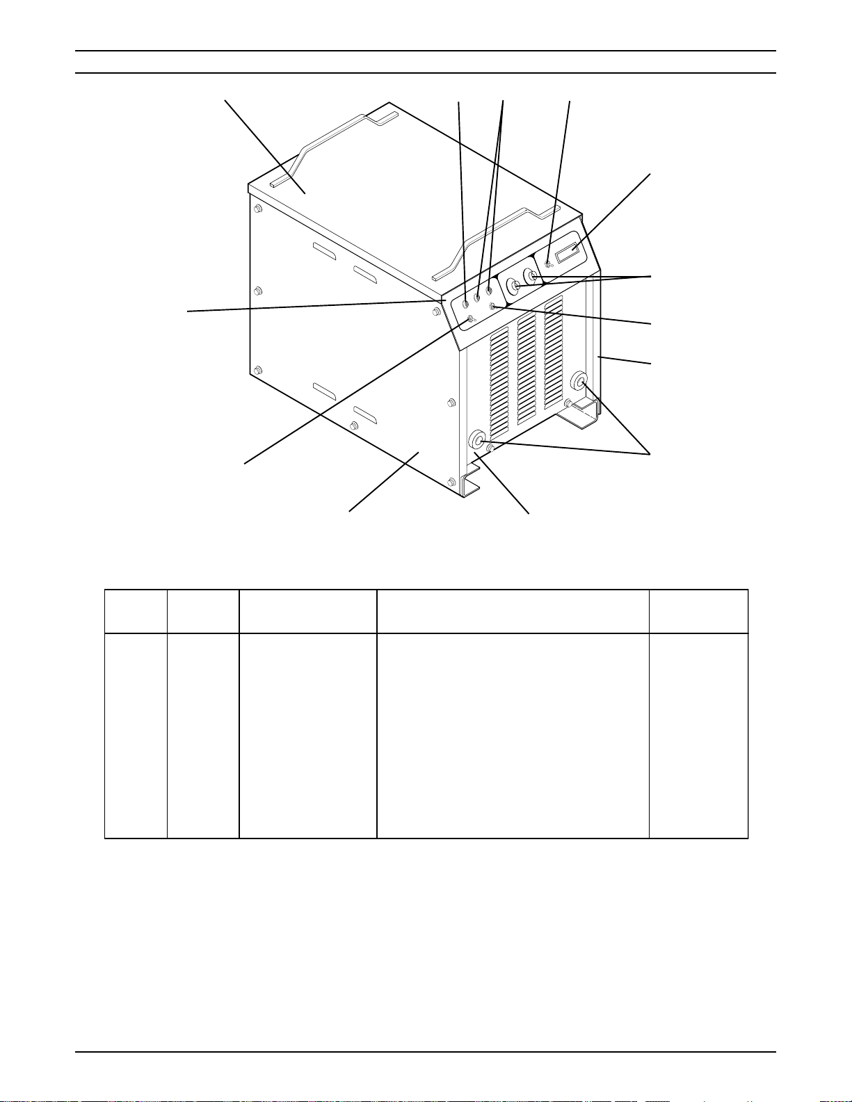
SECTION 6 REPLACEMENT PARTS
11
12
10
1
SVI 450i cvcc
+
2
3 (SW2)
4
5
3 (SW1)
-
6
7
ITEM
NO.
1
2
3
4
5
6
7
8
9
10
11
12
QTY
REQ.
1
2
2
1
2
2
1
2
1
1
1
1
1
9
Figure 6-1. SVI 450i cvcc (Front View)
PART
NO.
951526
951032
634515
951795
2062018
13730611
31129YL
13733935
32059GY
31128YL
672831
32057GY
31130YL
LAMP, WHITE
LAMP, RED
SWITCH, TOGGLE, SPDT
METER, DIGITAL
POTENTIOMETER, TRIM
KNOB (P/O ITEM NO. 5)
PANEL, RIGHT SIDE
CONNECTOR, FEMALE
PANEL, FRONT, SILKSCREENED
PANEL, LEFT SIDE
SWITCH, TOGGLE, SPDT
PANEL, CONTROL, SILKSCREENED
PANEL, TOP
DESCRIPTION
8
CIRCUIT
SYMBOL
PL1
PL2, PL3
SW1, SW2
DPM
ICP, VCP
SW3
28

SECTION 6 REPLACEMENT PARTS
1
REF: Matched set
of capacitors is part
of PB1 and PB2.
2
3
ITEM
NO.
1
2
3
QTY
REQ.
1
1
1
Figure 6-2. SVI 450i cvcc (Top View)
PART
NO.
31135
31133
31134
INDUCTOR (MOUNTED ON FRONT PART OF
CHASSIS BASE)
TRANSFORMER, MAIN (MOUNTED ON TOP
OF INDUCTOR)
TRANSFORMER, CONTROL (MOUNTED ON
CHASSIS BASE UNDER FAN MOTOR)
DESCRIPTION
CIRCUIT
SYMBOL
IND
MTR
CTR1
29

SECTION 6 REPLACEMENT PARTS
1
2
ITEM
NO.
1
2
QTY
REQ.
1
1
Figure 6-3. SVI 450i cvcc (Top View)
PART
NO. DESCRIPTION
31143
38082
TERMINAL BOARD, SCREEN PRINTED
PC BOARD ASSY, CONTROL
CIRCUIT
SYMBOL
TB
ICB
30

SECTION 6 REPLACEMENT PARTS
7
1
2,3
ITEM
NO.
1
2
3
4
5
6
7
QTY
REQ.
1
1
1
1
1
1
1
6
5
4
Figure 6-4. SVI 450i cvcc (Left Side View)
PART
NO.
674991
17282010
950516
950702
951023
17250005
951022
DESCRIPTION
PC BOARD ASSY, POWER
RESISTOR, 10 OHM, 100 W
CAPACITOR, 0.05 µF, 600 V
CAPACITOR, 0.01 µF, 125 V
MODULE, SCR
RESISTOR, 5 OHM, 50 W
INPUT BRIDGE MODULE
CIRCUIT
SYMBOL
PB1
R2
C5
C9
SCR1
R1
IBR
31

SECTION 6 REPLACEMENT PARTS
12
3,11
1
2 (R5), 3
4
5
6
7
10
ITEM
NO.
1
2
3
4
5
6
7
8
9
10
11
12
QTY
REQ.
1
2
3
1
1
1
1
4
1
1
1
1
9
8
Figure 6-5. SVI 450i cvcc (Right Side View)
PART
NO.
674991
17725005
950516
13735102
33938
993717
635686
951184
951085
950702
17282010
31132
PC BOARD ASSY, POWER
RESISTOR, 5 OHM, 25 W
CAPACITOR, 0.05 µF, 600 V
RELAY, 42 V, 3-POLE
CHOKE, COMMON MODE
TRANSFORMER
TERMINAL STRIP, 8-POSITION
DIODE, OUTPUT
SWITCH, THERMAL, 80 °C
CAPACITOR, 0.01 µF, 100 W
RESISTOR, 10 OHM, 100 W
SHUNT
DESCRIPTION
2 (R4), 3
CIRCUIT
SYMBOL
PB2
R4,5
C8
K2
L1
CTR2
T1
OBR1-4
TS1
C10
R3
SH
32

SECTION 6 REPLACEMENT PARTS
10
DIGITAL
CONTROL
OFF
ON
1
9
REMOTE
CONTROL
MAIN
POWER
2,3
8
7
115 AUX.
6
4
5
ITEM
NO.
1
2
3
4
5
6
7
8
9
10
QTY
REQ.
1
1
1
1
1
1
2
1
1
1
Figure 6-6. SVI 450i cvcc (Rear View)
PART
NO.
950822
680970
679384GY
950592
97W63
952219
950122
31126GY
951476
951475
SWITCH, ROTOR, 3PST
MOTOR, FAN
SHROUD, FAN
BLADE, FAN
CONNECTOR, CABLE GRIP
RECEPTACLE, 125 V, 15 A
CIRCUIT BREAKER, 10 A
REAR PANEL
RECEPTACLE, 14-PIN
RECEPTACLE, 19-PIN
DESCRIPTION
CIRCUIT
SYMBOL
LS
FM
J3
CB1,2
J2
J1
33

SECTION 6 REPLACEMENT PARTS
34

SECTION 6 REPLACEMENT PARTS
35

ESAB Welding & Cutting Products
PO Box 100545 Florence SC 29501-0545
ESAB Welding & Cutting Products, Florence, SC Welding Equipment
COMMUNICATION GUIDE - CUSTOMER SERVICES
A. CUSTOMER SERVICE QUESTIONS:
Order Entry Product Availability Pricing Delivery
Order Changes Saleable Goods Returns Shipping Information
Telephone: (800)362-7080 / Fax: (800) 634-7548
Telephone: (800)783-5360 / Fax: (800) 783-5362
Telephone: (800) 235-4012/ Fax: (888) 586-4670
B. ENGINEERING SERVICE: Telephone: (843) 664-4416 / Fax : (800) 446-5693
Welding Equipment Troubleshooting Hours: 7:30 AM to 5:00 PM EST
Warranty Returns Authorized Repair Stations
C. TECHNICAL SERVICE: Telephone: (800) ESAB-123/ Fax: (843) 664-4452
Part Numbers Technical Applications Hours: 8:00 AM to 5:00 PM EST
Performance Features Technical Specifications Equipment Recommendations
D. LITERATURE REQUESTS: Telephone: (843) 664-5562 / Fax: (843) 664-5548
E. WELDING EQUIPMENT REPAIRS: Telephone: (843) 664-4487 / Fax: (843) 664-5557
Repair Estimates Repair Status Hours: 7:30 AM to 3:30 PM EST
F. WELDING EQUIPMENT TRAINING:
Telephone: (843)664-4428 / Fax: (843) 679-5864
Training School Information and Registrations Hours: 7:30 AM to 4:00 PM EST
G. WELDING PROCESS ASSISTANCE:
Telephone: (800) ESAB-123 / Fax: (843) 664-4454 Hours: 7:30 AM to 4:00 PM EST
H. TECHNICAL ASST. CONSUMABLES:
Telephone : (800) 933-7070 Hours: 7:30 AM to 5:00 PM EST
Eastern Distribution Center
Central Distribution Center
Western Distribution Center
Hours: 7:30 AM to 4:00 PM EST
Telephone: (800) ESAB-123/ Fax: (843) 664-4452/ Web:http://www.esab.com
F15-071-D 12/2003 Printed in U.S.A.
IF YOU DO NOT KNOW WHOM TO CALL
Hours: 7:30 AM to 5:00 PM EST
 Loading...