

F-15-183-A
January, 1997
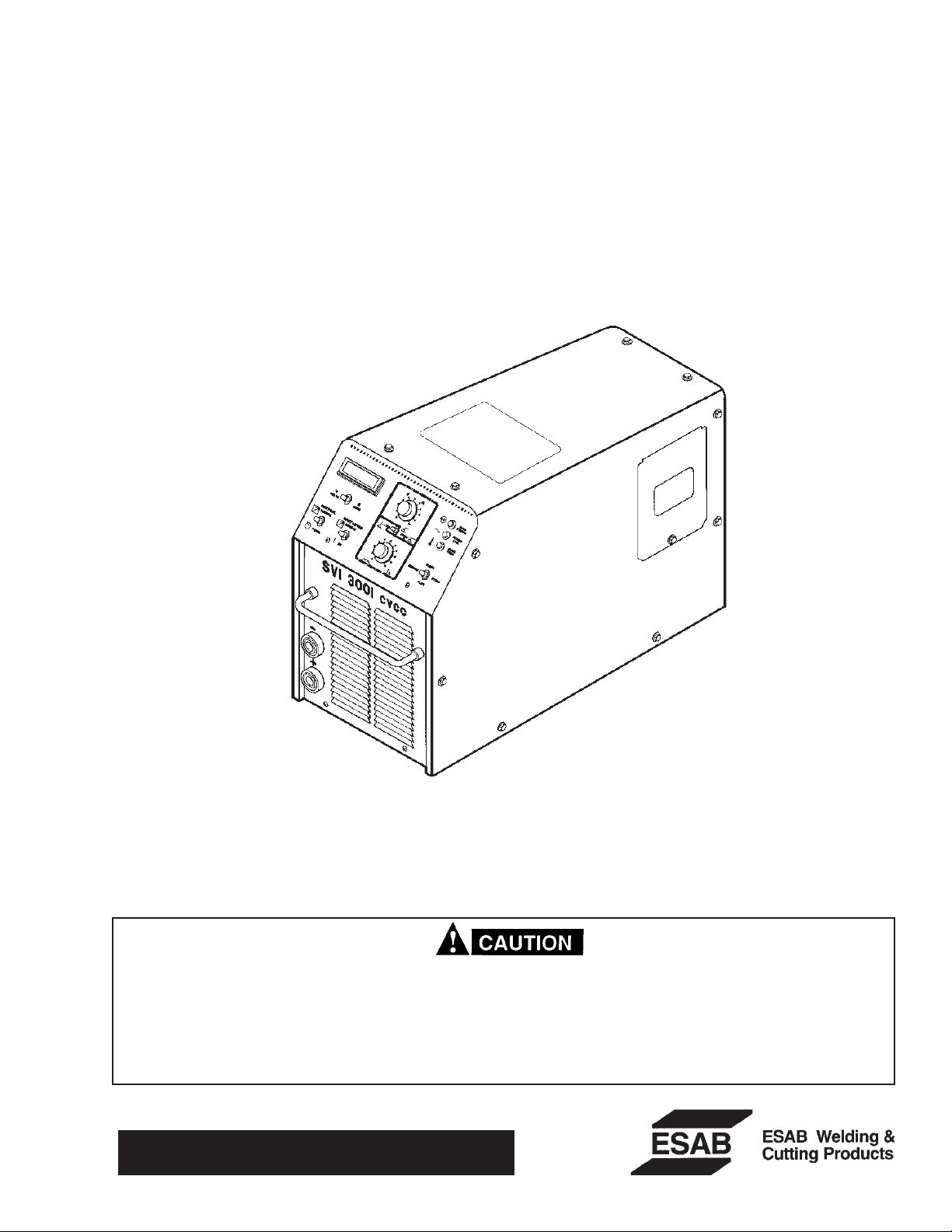
SVI 300i cvcc
POWER SOURCE
P/N 34835 - 230 (208-230) / 460 (440) V ac, 1- or 3-phase, 50/60 Hz
P/N 34834 - 230 (208-230) / 460 (440) V ac, 1- or 3-phase, 50/60 Hz, w/ APS (refer to supplement F-15-204)
P/N 34872 - 575 V ac, 3-phase, 50/60 Hz (refer to supplement F-15-205)
P/N 34873 - 400 (380-415) V ac, 3-phase, 50/60 Hz (refer to supplement F-15-206)
INSTRUCTION MANUAL
These INSTRUCTIONS are for experienced operators. If you are not fully familiar with the principles of operation and safe practices
for arc welding equipment, we urge you to read our booklet, "Precautions and Safe Practices for Arc Welding, Cutting, and
Gouging", Form 52-529. Do NOT permit untrained persons to install, operate, or maintain this equipment. Do NOT attempt to
install or operate this equipment until you have read and fully understand these instructions. If you do not fully understand these
instructions, contact your supplier for further information. Be sure to read the Safety Precautions before installing or operating
this equipment.
Be sure this information reaches the operator.
You can get extra copies through your supplier.

USER RESPONSIBILITY
This equipment will perform in conformity with the description thereof contained in this manual and accompanying labels and/or inserts when installed, operated, maintained and repaired in accordance with the instructions provided. This equipment must be checked periodically. Defective equipment should not be used. Parts
that are broken, missing, worn, distorted or contaminated should be replaced immediately. Should such repair or
replacement become necessary, the manufacturer recommends that a telephone or written request for service
advice be made to the Authorized Distributor from whom purchased.
This equipment or any of its parts should not be altered without the prior written approval of the manufacturer. The user of this equipment shall have the sole responsibility for any malfunction which results from improper use, faulty maintenance, damage, improper repair or alteration by anyone other than the manufacturer or
a service facility designated by the manufacturer.
i

PREFACE
The purpose of this manual is to provide the operator with all the information required to install and operate the
SVI 300i power source. Technical reference material is also provided to assist in troubleshooting the power source.
SCOPE
The technical reference material (schematics, wiring diagrams, etc.) contained in this manual relates to
P/N 34835 only. Data for the other models of this power source were not available at the time of this printing.
Contact ESAB at (803) 664-5540 for information if you have a power source other than P/N 34835.
Section 1 includes a general description of the SVI 300i. Sections 2-4 contain information necessary to install, operate,
and maintain the power source. Sections 5-6 contain schematic diagrams, wiring diagrams, and parts lists that support
troubleshooting and repair of the power source. At the time of this printing, detailed troubleshooting procedures were
not available. If it is determined that the SVI 300i is not operating properly (refer to section 5 - paragraph 5.2), the
operator should contact ESAB at (803) 664-4416.
The following is a list of terms/acronyms used throughout this manual.
CC Constant Current
CV Constant Voltage
GMAW Gas Metal Arc Welding, CV mode (same as MIG)
GMAW-P Gas Metal Arc Welding - Pulsed, CV mode (same as pulsed MIG)
GTAW Gas Tungsten Arc Welding, CC mode (same as TIG)
MIG Metal Inert Gas, CV mode (same as GMAW)
SMAW Shielded Metal Arc Welding, CC mode (same as Stick)
Stick Stick Welding, CC mode (same as SMAW)
TIG Tungsten Inert Gas, CC mode (same as GTAW)
ii

TABLE OF CONTENTS
SECTION TITLE PAGE
PARAGRAPH
SECTION 1 DESCRIPTION ................................................................................................. 7
1.1 General ............................................................................................................. 7
1.2 Duty Cycle ........................................................................................................ 7
1.3 Volt-Ampere Curves ......................................................................................... 7
SECTION 2 INSTALLATION................................................................................................ 9
2.1 General ............................................................................................................. 9
2.2 Required Tools ................................................................................................. 9
2.3 Unpacking and Placement................................................................................ 9
2.4 Input Connections............................................................................................. 10
2.5 Output Connections .......................................................................................... 13
SECTION 3 OPERATION .................................................................................................... 16
3.1 General ............................................................................................................. 16
3.2 Welding Controls / Indicators ............................................................................ 16
3.3 MIG / GMAW (CV) Operation ........................................................................... 17
3.4 TIG / GTAW (CC) Operation............................................................................. 18
3.5 Stick / SMAW (CC) Operation........................................................................... 19
SECTION 4 MAINTENANCE ............................................................................................... 20
4.1 General ............................................................................................................. 20
4.2 Inspection and Cleaning ................................................................................... 20
SECTION 5 TROUBLESHOOTING ..................................................................................... 21
5.1 General ............................................................................................................. 21
5.2 Functionality Check .......................................................................................... 21
SECTION 6 REPLACEMENT PARTS ................................................................................. 27
6.1 General ............................................................................................................. 27
6.2 Spare Parts....................................................................................................... 32
iii
SECTION SAFETY PRECAUTIONS
WARNING: These Safety Precautions are for
your protection. They summarize precautionary information from the references listed in
Additional Safety Information section. Before
performing any installation or operating procedures, be
sure to read and follow the safety precautions listed below
as well as all other manuals, material safety data sheets,
labels, etc. Failure to observe Safety Precautions can result
in injury or death.
PROTECT YOURSELF AND OTHERS
Some welding, cutting, and gouging
processes are noisy and require ear
protection. The arc, like the sun, emits
ultraviolet (UV) and other radiation and
can injure skin and eyes. Hot metal can cause burns.
Training in the proper use of the processes and equipment is essential to prevent accidents. Therefore:
1. Always wear safety glasses with side shields in any work
area, even if welding helmets, face shields, and goggles
are also required.
2. Use a face shield fitted with the correct filter and cover
plates to protect your eyes, face, neck, and ears from
sparks and rays of the arc when operating or observing
operations. Warn bystanders not to watch the arc and
not to expose themselves to the rays of the electric-arc
or hot metal.
3. Wear flameproof gauntlet type gloves, heavy long-sleeve
shirt, cuffless trousers, high-topped shoes, and a welding helmet or cap for hair protection, to protect against
arc rays and hot sparks or hot metal. A flameproof apron
may also be desirable as protection against radiated
heat and sparks.
4. Hot sparks or metal can lodge in rolled up sleeves,
trouser cuffs, or pockets. Sleeves and collars should be
kept buttoned, and open pockets eliminated from the
front of clothing
5. Protect other personnel from arc rays and hot sparks
with a suitable non-flammable partition or curtains.
6. Use goggles over safety glasses when chipping slag or
grinding. Chipped slag may be hot and can fly far.
Bystanders should also wear goggles over safety glasses.
FIRES AND EXPLOSIONS -- Heat from
flames and arcs can start fires. Hot slag
or sparks can also cause fires and explosions. Therefore:
1. Remove all combustible materials well away from the
work area or cover the materials with a protective nonflammable covering. Combustible materials include wood,
cloth, sawdust, liquid and gas fuels, solvents, paints and
coatings, paper, etc.
2. Hot sparks or hot metal can fall through cracks or
crevices in floors or wall openings and cause a hidden
smoldering fire or fires on the floor below. Make certain
that such openings are protected from hot sparks and
metal.“
3. Do not weld, cut or perform other hot work until the
workpiece has been completely cleaned so that there
are no substances on the workpiece which might produce flammable or toxic vapors. Do not do hot work on
closed containers. They may explode.
4. Have fire extinguishing equipment handy for instant use,
such as a garden hose, water pail, sand bucket, or
portable fire extinguisher. Be sure you are trained in its
use.
5. Do not use equipment beyond its ratings. For example,
overloaded welding cable can overheat and create a fire
hazard.
6. After completing operations, inspect the work area to
make certain there are no hot sparks or hot metal which
could cause a later fire. Use fire watchers when necessary.
7. For additional information, refer to NFPA Standard 51B,
"Fire Prevention in Use of Cutting and Welding Pro-
--
1
cesses", available from the National Fire Protection Association, Batterymarch Park, Quincy, MA 02269.
ELECTRICAL SHOCK -- Contact with live
electrical parts and ground can cause
severe injury or death. DO NOT use AC
welding current in damp areas, if movement is confined, or if there is danger of
falling.
1. Be sure the power source frame (chassis) is connected
to the ground system of the input power.
2. Connect the workpiece to a good electrical ground.
3. Connect the work cable to the workpiece. A poor or
missing connection can expose you or others to a fatal
shock.
4. Use well-maintained equipment. Replace worn or damaged cables.
5. Keep everything dry, including clothing, work area, cables,
torch/electrode holder, and power source.
6. Make sure that all parts of your body are insulated from
work
and from ground.
7. Do not stand directly on metal or the earth while working
in tight quarters or a damp area; stand on dry boards or
an insulating platform and wear rubber-soled shoes.
8. Put on dry, hole-free gloves before turning on the power.
9. Turn off the power before removing your gloves.
10. Refer to ANSI/ASC Standard Z49.1 (listed on next page)
for specific grounding recommendations. Do not mistake
the work lead for a ground cable.
ELECTRIC AND MAGNETIC FIELDS —
May be dangerous. Electric current flowing through any conductor causes localized Electric and Magnetic Fields
(EMF). Welding and cutting current creates EMF around welding cables and
welding machines. Therefore:
1. Welders having pacemakers should consult their physician before welding. EMF may interfere with some pacemakers.
2. Exposure to EMF may have other health effects which are
unknown.
3. Welders should use the following procedures to minimize
exposure to EMF:
A. Route the electrode and work cables together. Secure
them with tape when possible.
B. Never coil the torch or work cable around your body.
C. Do not place your body between the torch and work
cables. Route cables on the same side of your body.
D. Connect the work cable to the workpiece as close as
possible to the area being welded.
E. Keep welding power source and cables as far away
from your body as possible.
10/2001
SECTION SAFETY PRECAUTIONS
FUMES AND GASES -- Fumes and
gases, can cause discomfort or harm,
particularly in confined spaces. Do
not breathe fumes and gases. Shielding gases can cause asphyxiation.
Therefore:
1. Always provide adequate ventilation in the work area by
natural or mechanical means. Do not weld, cut, or gouge
on materials such as galvanized steel, stainless steel,
copper, zinc, lead, beryllium, or cadmium unless positive
mechanical ventilation is provided. Do not breathe fumes
from these materials.
2. Do not operate near degreasing and spraying operations. The heat or arc rays can react with chlorinated
hydrocarbon vapors to form phosgene, a highly toxic
gas, and other irritant gases.
3. If you develop momentary eye, nose, or throat irritation
while operating, this is an indication that ventilation is not
adequate. Stop work and take necessary steps to improve ventilation in the work area. Do not continue to
operate if physical discomfort persists.
4. Refer to ANSI/ASC Standard Z49.1 (see listing below)
for specific ventilation recommendations.
5. WARNING: This product, when used for welding or
cutting, produces fumes or gases which
contain chemicals known to the State of
California to cause birth defects and, in
some cases, cancer. (California Health &
Safety Code
CYLINDER HANDLING -- Cylinders, if
mishandled, can rupture and violently
release gas. Sudden rupture of cylinder, valve, or relief device can injure or
kill. Therefore:
1. Use the proper gas for the process and use the proper
pressure reducing regulator designed to operate from
the compressed gas cylinder. Do not use adaptors.
Maintain hoses and fittings in good condition. Follow
manufacturer's operating instructions for mounting regulator to a compressed gas cylinder.
2. Always secure cylinders in an upright position by chain
or strap to suitable hand trucks, undercarriages, benches,
walls, post, or racks. Never secure cylinders to work
tables or fixtures where they may become part of an
electrical circuit.
3. When not in use, keep cylinder valves closed. Have
valve protection cap in place if regulator is not connected. Secure and move cylinders by using suitable
hand trucks. Avoid rough handling of cylinders.
4. Locate cylinders away from heat, sparks, and flames.
Never strike an arc on a cylinder.
5. For additional information, refer to CGA Standard P-1,
"Precautions for Safe Handling of Compressed Gases in
Cylinders", which is available from Compressed Gas
Association, 1235 Jefferson Davis Highway, Arlington,
VA 22202.
§25249.5 et seq.)
EQUIPMENT MAINTENANCE -- Faulty or
improperly maintained equipment can
cause injury or death. Therefore:
1. Always have qualified personnel perform the installation, troubleshooting, and maintenance work. Do not
perform any electrical work unless you are qualified to
perform such work.
2. Before performing any maintenance work inside a power
source, disconnect the power source from the incoming
electrical power.
3. Maintain cables, grounding wire, connections, power
cord, and power supply in safe working order. Do not
operate any equipment in faulty condition.
4. Do not abuse any equipment or accessories. Keep
equipment away from heat sources such as furnaces,
wet conditions such as water puddles, oil or grease,
corrosive atmospheres and inclement weather.
5. Keep all safety devices and cabinet covers in position
and in good repair.
6. Use equipment only for its intended purpose. Do not
modify it in any manner.
ADDITIONAL SAFETY INFORMATION -- For
more information on safe practices for electric arc welding and cutting equipment, ask
your supplier for a copy of "Precautions and
Safe Practices for Arc Welding, Cutting and
Gouging", Form 52-529.
The following publications, which are available from the
American Welding Society, 550 N.W. LeJuene Road, Miami, FL 33126, are recommended to you:
1. ANSI/ASC Z49.1 - "Safety in Welding and Cutting"
2. AWS C5.1 - "Recommended Practices for Plasma Arc
Welding"
3. AWS C5.2 - "Recommended Practices for Plasma Arc
Cutting"
4. AWS C5.3 - "Recommended Practices for Air Carbon
Arc Gouging and Cutting"
5. AWS C5.5 - "Recommended Practices for Gas Tungsten
Arc Welding“
6. AWS C5.6 - "Recommended Practices for Gas Metal Arc
Welding"“
7. AWS SP - "Safe Practices" - Reprint, Welding Handbook.
8. ANSI/AWS F4.1, "Recommended Safe Practices for
Welding and Cutting of Containers That Have Held
Hazardous Substances."
MEANING OF SYMBOLS - As used throughout this manual: Means Attention! Be Alert!
Your safety is involved.
Means immediate hazards which, if
not avoided, will result in immediate,
serious personal injury or loss of life.
Means potential hazards which could
result in personal injury or loss of life.
Means hazards which could result in
minor personal injury.
2
SECTION PRECAUCION DE SEGURIDAD
ADVERTENCIA: Estas Precauciones de Seguridad
son para su protección. Ellas hacen resumen de
en la sección "Información Adicional Sobre La Seguridad". Antes
de hacer cualquier instalación o procedimiento de operación ,
asegúrese de leer y seguir las precauciones de seguridad listadas
a continuación así como también todo manual, hoja de datos de
seguridad del material, calcomanias, etc. El no observar las
Precauciones de Seguridad puede resultar en daño a la persona
el sol , emite rayos ultravioleta (UV) y otras radiaciones que
pueden dañar la piel y los ojos. El metal caliente causa
quemaduras. EL entrenamiento en el uso propio de los
equipos y sus procesos es esencial para prevenir
accidentes. Por lo tanto:
información proveniente de las referencias listadas
o muerte
PROTEJASE USTED Y A LOS DEMAS-Algunos procesos de soldadura, corte y
ranurado son ruidosos y requiren
protección para los oídos. El arco, como
.
1. Utilice gafas de seguridad con protección a los lados siempre
que esté en el área de trabajo, aún cuando esté usando careta
de soldar, protector para su cara u otro tipo de protección.
2. Use una careta que tenga el filtro correcto y lente para proteger
sus ojos, cara, cuello, y oídos de las chispas y rayos del arco
cuando se esté operando y observando las operaciones. Alerte
a todas las personas cercanas de no mirar el arco y no exponerse
a los rayos del arco eléctrico o el metal fundido.
3. Use guantes de cuero a prueba de fuego, camisa pesada de
mangas largas, pantalón de ruedo liso, zapato alto al tobillo, y
careta de soldar con capucha para el pelo, para proteger el
cuerpo de los rayos y chispas calientes provenientes del metal
fundido. En ocaciones un delantal a prueba de fuego es
necesario para protegerse del calor radiado y las chispas.
4. Chispas y partículas de metal caliente puede alojarse en las
mangas enrolladas de la camisa , el ruedo del pantalón o los
bolsillos. Mangas y cuellos deberán mantenerse abotonados,
bolsillos al frente de la camisa deberán ser cerrados o eliminados.
5. Proteja a otras personas de los rayos del arco y chispas calientes
con una cortina adecuada no-flamable como división.
6. Use careta protectora además de sus gafas de seguridad
cuando esté removiendo escoria o puliendo. La escoria puede
estar caliente y desprenderse con velocidad. Personas cercanas
deberán usar gafas de seguridad y careta protectora.
FUEGO Y EXPLOSIONES -- El calor de
las flamas y el arco pueden ocacionar
fuegos. Escoria caliente y las chispas
pueden causar fuegos y explosiones.
Por lo tanto:
Remueva todo material combustible lejos del área de trabajo o
1.
cubra los materiales con una cobija a prueba de fuego. Materiales
combustibles incluyen madera, ropa, líquidos y gases flamables,
solventes, pinturas, papel, etc.
2. Chispas y partículas de metal pueden introducirse en las grietas
y agujeros de pisos y paredes causando fuegos escondidos en
otros niveles o espacios. Asegúrese de que toda grieta y agujero
esté cubierto para proteger lugares adyacentes contra fuegos.
3. No corte, suelde o haga cualquier otro trabajo relacionado hasta
que la pieza de trabajo esté totalmente limpia y libre de
substancias que puedan producir gases inflamables o vapores
tóxicos. No trabaje dentro o fuera de contenedores o tanques
cerrados. Estos pueden explotar si contienen vapores inflamables.
4. Tenga siempre a la mano equipo extintor de fuego para uso
instantáneo, como por ejemplo una manguera con agua, cubeta
con agua, cubeta con arena, o extintor portátil. Asegúrese que
usted esta entrenado para su uso.
5. No use el equipo fuera de su rango de operación. Por ejemplo,
el calor causado por cable sobrecarga en los cables de soldar
pueden ocasionar un fuego.
6. Después de termirar la operación del equipo, inspeccione el área
de trabajo para cerciorarse de que las chispas o metal caliente
ocasionen un fuego más tarde. Tenga personal asignado para
vigilar si es necesario.
7. Para información adicional , haga referencia a la publicación
NFPA Standard 51B, "Fire Prevention in Use of Cutting and
Welding Processes", disponible a través de la National Fire
Protection Association, Batterymarch Park, Quincy, MA 02269.
CHOQUE ELECTRICO -- El contacto con las
partes eléctricas energizadas y tierra
puede causar daño severo o muerte. NO
use soldadura de corriente alterna (AC)
en áreas húmedas, de movimiento
confinado en lugares estrechos o si hay
posibilidad de caer al suelo.
1. Asegúrese de que el chasis de la fuente de poder esté
conectado a tierra através del sistema de electricidad primario.
2. Conecte la pieza de trabajo a un buen sistema de tierra física.
3. Conecte el cable de retorno a la pieza de trabajo. Cables y
conductores expuestos o con malas conexiones pueden exponer
al operador u otras personas a un choque eléctrico fatal.
4. Use el equipo solamente si está en buenas condiciones.
Reemplaze cables rotos, dañados o con conductores expuestos.
5. Mantenga todo seco, incluyendo su ropa, el área de trabajo, los
cables, antorchas, pinza del electrodo, y la fuente de poder.
6. Asegúrese que todas las partes de su cuerpo están insuladas
de ambos, la pieza de trabajo y tierra.
7. No se pare directamente sobre metal o tierra mientras trabaja en
lugares estrechos o áreas húmedas; trabaje sobre un pedazo de
madera seco o una plataforma insulada y use zapatos con suela
de goma.
8. Use guantes secos y sin agujeros antes de energizar el equipo.
9. Apage el equipo antes de quitarse sus guantes.
10. Use como referencia la publicación ANSI/ASC Standard Z49.1
(listado en la próxima página) para recomendaciones específicas
de como conectar el equipo a tierra. No confunda el cable de
soldar a la pieza de trabajo con el cable a tierra.
CAMPOS ELECTRICOS Y MAGNETICOS Son peligrosos. La corriente eléctrica fluye
através de cualquier conductor causando
a nivel local Campos Eléctricos y
Magnéticos (EMF). Las corrientes en el
área de corte y soldadura, crean EMF
alrrededor de los cables de soldar y las
maquinas. Por lo tanto:
1. Soldadores u Operadores que use marca-pasos para el corazón
deberán consultar a su médico antes de soldar. El Campo
Electromagnético (EMF) puede interferir con algunos marcapasos.
2. Exponerse a campos electromagnéticos (EMF) puede causar
otros efectos de salud aún desconocidos.
3. Los soldadores deberán usar los siguientes procedimientos para
minimizar exponerse al EMF:
A. Mantenga el electrodo y el cable a la pieza de trabajo juntos,
hasta llegar a la pieza que usted quiere soldar. Asegúrelos uno
junto al otro con cinta adhesiva cuando sea posible.
B. Nunca envuelva los cables de soldar alrededor de su cuerpo.
C. Nunca ubique su cuerpo entre la antorcha y el cable, a la pieza
de trabajo. Mantega los cables a un sólo lado de su cuerpo.
D. Conecte el cable de trabajo a la pieza de trabajo lo más
cercano posible al área de la soldadura.
E. Mantenga la fuente de poder y los cables de soldar lo más
lejos posible de su cuerpo.
3

SECTION PRECAUCION DE SEGURIDAD
HUMO Y GASES -- El humo y los gases,
pueden causar malestar o daño,
particularmente en espacios sin
ventilación. No inhale el humo o gases. El
gas de protección puede causar falta de
oxígeno.
Por lo tanto:
1. Siempre provea ventilación adecuada en el área de
trabajo por medio natural o mecánico. No solde, corte, o
ranure materiales con hierro galvanizado, acero inoxidable,
cobre, zinc, plomo, berílio, o cadmio a menos que provea
ventilación mecánica positiva . No respire los gases
producidos por estos materiales.
2. No opere cerca de lugares donde se aplique substancias
químicas en aerosol. El calor de los rayos del arco pueden
reaccionar con los vapores de hidrocarburo clorinado
para formar un fosfógeno, o gas tóxico, y otros irritant es.
3. Si momentáneamente desarrolla inrritación de ojos, nariz
o garganta mientras est á operando, es indicación de que
la ventilación no es apropiada. Pare de trabajar y tome
las medidas necesarias para mejorar la ventilación en
el área de trabajo. No continúe operando si el malestar
físico persiste.
4. Haga referencia a la publicación ANSI/ASC Standard
Z49.1 (Vea la lista a continuación) para recomendaciones
específicas en la ventilación.
5. ADVERTENCIA-- Este producto cuando se utiliza para
soldaduras o cortes, produce humos
o gases, los cuales contienen
químicos conocidos por el Estado
de California de causar defectos en
el nacimiento, o en algunos casos,
Cancer. (California Health & Safety
§25249.5 et seq.)
Code
MANEJO DE CILINDROS-- Los
cilindros, si no son manejados
correctamente, pueden romperse y
liberar violentamente gases. Rotura
repentina del cilindro, válvula, o
válvula de escape puede causar daño
o muerte. Por lo tanto:
1. Utilize el gas apropiado para el proceso y utilize un
regulador diseñado para operar y reducir la presión del
cilindro de gas . No utilice adaptadores. Mantenga las
mangueras y las conexiones en buenas condiciones.
Observe las instrucciones de operación del manufacturero
para montar el regulador en el cilindro de gas comprimido.
2. Asegure siempre los cilindros en posición vertical y
amárrelos con una correa o cadena adecuada para
asegurar el cilindro al carro, transportes, tablilleros, paredes,
postes, o armazón. Nunca asegure los cilindros a la mesa
de trabajo o las piezas que son parte del circuito de
soldadura . Este puede ser parte del circuito elélectrico.
3. Cuando el cilindro no está en uso, mantenga la válvula del
cilindro cerrada. Ponga el capote de protección sobre la
válvula si el regulador no está conectado. Asegure y
mueva los cilindros utilizando un carro o transporte
adecuado. Evite el manejo brusco de los
MANTENIMIENTO DEL EQUIPO -- Equipo
defectuoso o mal mantenido puede causar
daño o muerte. Por lo tanto:
1. Siempre tenga personal cualificado para efectuar l
a instalación, diagnóstico, y mantenimiento del
equipo. No ejecute ningún trabajo eléctrico a menos
que usted esté cualificado para hacer el trabajo.
2. Antes de dar mantenimiento en el interior de la
fuente de poder, desconecte la fuente de poder del
suministro de electricidad primaria.
3. Mantenga los cables, cable a tierra, conexciones, cable
primario, y cualquier otra fuente de poder en buen
estado operacional. No opere ningún equipo en
malas condiciones.
4. No abuse del equipo y sus accesorios. Mantenga el
equipo lejos de cosas que generen calor como
hornos, también lugares húmedos como charcos de
agua , aceite o grasa, atmósferas corrosivas y las
inclemencias del tiempo.
5. Mantenga todos los artículos de seguridad y coverturas
del equipo en su posición y en buenas condiciones.
6. Use el equipo sólo para el propósito que fue diseñado.
No modifique el equipo en ninguna manera.
INFORMACION ADICIONAL DE SEGURIDAD -Para más información sobre las prácticas de
seguridad de los equipos de arco eléctrico para
soldar y cortar, pregunte a su suplidor por una
copia de "Precautions and Safe Practices for Arc
Welding, Cutting and Gouging-Form 52-529.
Las siguientes publicaciones, disponibles através de la
American Welding Society, 550 N.W. LeJuene Road, Miami,
FL 33126, son recomendadas para usted:
1. ANSI/ASC Z49.1 - "Safety in Welding and Cutting"
2. AWS C5.1 - "Recommended Practices for Plasma Arc
Welding"
3. AWS C5.2 - "Recommended Practices for Plasma Arc
Cutting"
4. AWS C5.3 - "Recommended Practices for Air Carbon Arc
Gouging and Cutting"
5. AWS C5.5 - "Recommended Practices for Gas Tungsten
Arc Welding“
6. AWS C5.6 - "Recommended Practices for Gas Metal Arc
Welding"“
7. AWS SP - "Safe Practices" - Reprint, Welding Handbook.
8. ANSI/AWS F4.1, "Recommended Safe Practices for Welding and Cutting of Containers That Have Held Hazardous
Substances."
SIGNIFICADO DE LOS SIMBOLOS -Según usted avanza en la lectura de
este folleto: Los Símbolos Significan
¡Atención! ¡Esté Alerta! Se trata de su
seguridad.
Significa riesgo inmediato que, de no ser
evadido, puede resultar inmediatamente
en serio daño personal o la muerte.
Significa el riesgo de un peligro potencial
que puede resultar en serio daño personal o la muerte.
Significa el posible riesgo que puede
resultar en menores daños a la persona.
4

SECTION PRÉCAUTIONS DE SÉCURITÉ
AVERTISSEMENT: Ces règles de sécurité ont pour objet
d’ assurer votre protection. Veillez à lire et à observer les
précautions énoncées ci-dessous avant de monter l’
équipement ou de commercer à l’utiliser. Tout défaut
d’observation de ces précautions risque d’entraîner des
blessures graves ou mortelles.
1. PROTECTION INDIVIDUELLE-- Les brûlures de la
peau et des yeux dues au rayonnement de l’arc
électrique ou du métal incandescent, lors du soudage
au plasma ou à l’électrode ou lors du gougeage à
l’arc, peuvent s’avérer plus graves que celles résultant
d’une exposition prolongée au soleil. Aussi convientil d’observer les précautions suivantes:
a. Portez un écran facial adéquat muni des plaques
protectrices et des verres filtrants appropriés afin de
vous protéger les yeux, le visage, le cou et les
oreilles des étincelles et du rayonnement de l’arc
électrique lorsque vous effectuez des soudures ou
des coupes ou lorsque vous en observez l’exécution.
AVERTISSEZ les personnes se trouvant à proximité
de façon à ce qu’elles ne regardent pas l’arc et à ce
qu’elles ne s’exposent pas à son rayonnement, ni à
celui du métal incandescent.
b. Portez des gants ignifugés à crispins, une tunique
épaisse à manches longues, des pantalons sans
rebord, des chaussures à embout d’acier et un
casque de soudage ou une calotte de protection, afin
d’éviter d’exposer la peau au rayonnement de l’arc
électrique ou du métal incandescent. ll est également
souhaitable d’utiliser un tablier ininflammable de
façon à se protéger des étincelles et du rayonnement
thermique.
c. Les étincelles ou les projections de métal incandes-
cent risquent de se loger dans des manches
retroussées, des bords relevés de pantalons ou dans
des poches. Aussi convient-il de garder boutonnés le
col et les manches et de porter des vêtements sans
poches à l’avant.
d. Protégez des étincelles et du rayonnement de l’arc
électrique les autres personnes travaillant à proximité
à l’aide d’un écran ininflammable adéquat.
e. Ne jamais omettre de porter des lunettes de sécurité
lorsque vous vous trouvez dans un secteur où l’on
effectue des opérations de soudage ou de coupage à
l’arc. Utilisez des lunettes de sécurité à écrans ou
verres latéraux pour piquer ou meûler le laitier. Les
piquetures incandescentes de laitier peuvent être
projetées à des distances considérables. Les
personnes se trouvant à proximité doivent également
porter des lunettes de protection.
f. Le gougeage à l’arc et le soudage à l’arc au plasma
produisent un niveau de bruit extrêmement élevé (de
100 à 114 dB) et exigent par conséquent l’emploi de
dispositifs appropriés de protection auditive.
2 PRÉVENTION DES INCENDES-- Les projections de
laitier incandescent ou d’étincelles peuvent provoquer
de graves incendies au contact de matériaux combustibles solides, liquides ou gazeux. Aussi faut-il
observer les précautions suivantes:
a. Éloigner suffisamment tous les matériaux combustibles
du secteur où l’on exécute des soudures ou des coupes
à l’arc, à moins de les recouvrir complètement d’une
bâche non-inflammable. Ce type de matériaux comprend
notamment le bois, les vêtements, la sciure, l’essence,
le kérosène, les peintures, les solvants, le gaz naturel,
l’acétylène, le propane et autres substances combustibles semblables.
b. Les étincelles ou les projections de métal incandescent
peuvent tomber dans des fissures du plancher ou dans
des ouvertures des murs et y déclencher une ignition
lente cachée. Veiller à protéger ces ouvertures des
étincelles et des projections de métal.
c. N’exécutez pas de soudures, de coupes, d’opérations
de gougeage ou autres travaux à chaud à la surface de
barils, bidons, réservoirs ou autres contenants usagés,
avant de les avoir nettoyés de toute trace de substance
susceptible de produire des vapeurs inflammables ou
toxiques.
d. En vue d’assurer la prévention des incendies, il convient
de disposer d’un matériel d’extinction prêt à servir
immédiatement, tel qu’un tuyau d’arrosage, un seau à
eau, un seau de sable ou un extincteur portatif.
e. Une fois le travail à l’arc terminé, inspectez le secteur de
façon à vous assurer qu’aucune étincelle ou projection
de métal incandescent ne risque de provoquer
ultérieurement un feu.
3. CHOC ÉLECTRIQUE-- Le gougeage à l’arc et à l’arc au
plasma exige l’emploi de tensions à vide relativement
importantes; or, celles-ci risquent de causer des
dommages corporels graves et même mortels en cas
d’utilisation inadéquate. La gravité du choc électrique
reçu dépend du chemin suivi par le courant à travers le
corps humain et de son intensité.
a. Ne laissez jamais de surfaces métalliques sous tension
venir au contact direct de la peau ou de vêtements
humides. Veillez à porter des gants bien secs.
b. Si vous devez effectuer un travail sur une surface
métallique ou dans un secteur humide, veillez à assu-rer
votre isolation corporelle en portant des gants secs et
des chaussures à semelles de caoutchouc et en vous
tenant sur une planche ou une plate-forme sèche.
c. Mettez toujours à la terre le poste de soudage/coupage
en le reliant par un câble à une bonne prise de terre.
d. N’utilisez jamais de câbles usés ou endommagés. Ne
surchargez jamais le câble. Utilisez toujours un
équipement correctement entretenu.
e. Mettez l’équipement hors tension lorsqu’il n’est pas en
service. une mise à la masse accidentelle peut en effet
provoquer une surchauffe de l’équipement et un danger
d’incendie. Ne pas enrouler ou passer le câble autour
d’une partie quelconque du corps.
f. Vérifiez si le câble de masse est bien relié à la pièce en
un point aussi proche que possible de la zone de travail.
Le branchement des câbles de masse à l’ossature du
bâtiment ou en un point éloigné de la zone de travail
augmente en effet le risque de passage d’un courant de
sortie par des chaînes de
5

SECTION PRÉCAUTIONS DE SÉCURITÉ
levage, des câbles de grue ou divers chemins
électriques.
g. Empêchez l’apparition de toute humidité, notamment
sur vos vêtements, à la surface de l’emplacement de
travail, des câbles, du porte-électrode et du poste de
soudage/coupage. Réparez immédiatement toute fuite
d’eau.
4. VENTILATION-- La respiration prolongée des fumées
résultant des opérations de soudage/coupage, à
l’intérieur, d’un local clos, peut provoquer des malaises et des dommages corporels. Aussi convient-il
d’observer les précautions suivantes:
a. Assurez en permanence une aération adéquate de
l’emplacement de travail en maintenant une ventilation naturelle ou à l’aide de moyens mécaniques.
N’effectuez jamais de travaux de soudage ou de
coupage sur des matériaux de zinc, de plomb, de
beryllium ou de cadmium en l’absence de moyens
mécaniques de ventilation capables d’empêcher
l’inhalation des fumées dégagées par ces matériaux.
b. N’effectuez jamais de travaux de soudage ou de
coupage à proximité de vapeurs d’hydrocarbure chloré
résultant d’opérations voisines de dégraissage ou de
pulvérisation. La chaleur dégagée ou le rayonnement
de l’arc peut déclencher la formation de phosgène -gaz particulièrement toxique -- et d’autres gaz irritants, à partir des vapeurs de solvant.
c. Une irritation momentanée des yeux, du nez ou de la
gorge constatée au cours de l’utilisation de
l’équipement dénote un défaut de ventilation. Arrêtezvous de travailler afin de prendre les mesures nécessaires à l’amélioration de la ventilation. Ne poursuivez
pas l’opération entreprise si le malaise persiste.
d. Certaines commandes comportent des canalisations
où circule de l’hydrogène. L’armoire de commande est
munie d’un ventilateur destiné à empêcher la formation de poches d’hydrogène, lesquelles présentent un
danger d’explosion; ce ventilateur ne fonctionne que
si l’interrupteur correspondant du panneau avant se
trouve placé en position ON (Marche). Veillez à
manœuvrer cette commande en vérifiant si le couvercle
est bien en place, de façon à assurer l’efficacité de la
ventilation ainsi réalisée. Ne jamais débrancher le
ventilateur.
e. Les fumées produites par l’opération de soudage ou
de coupage peuvent s’avérer toxiques. Aussi est-il
nécessaire de disposer en permanence d’un dispositif
adéquat de ventilation de type aspirant, afin d’éliminer du voisinage de l’opérateur tout dégagement de
fumée visible.
f. Consultez les recommandations particulières en matière
de ventilation indiquées à l’alinéa 6 de la norme Z49.1
de l’AWS.
5. ENTRETIEN DE L’ÉQUIPEMENT-- Un équipement
entretenu de façon défectueuse ou inadéquate risque
non seulement de réaliser un travail de mauvaise
qualité mais, chose plus grave encore, d’entraîner des
dommages corporels graves, voire mortels en
déclenchant des incendies ou des chocs électriques.
Observez par conséquent les précautions suivantes:
a. Efforcez-vous de toujours confier à un personnel qua-
lifié l’installation, le dépannage et l’entretien du poste
de soudage et de coupage. N’effectuez aucune
réparation électrique sur l’équipement à moins d’être
qua-lifié à cet effet.
b. Ne procédez jamais à une tâche d’entretien quelconque
à l’intérieur du poste de soudage/coupage, avant
d’avoir débranché l’alimentation électrique.
c. Maintenez en bon état de fonctionnement les câbles,
le câble de masse, les branchements, le cordon
d’alimentation et le poste de soudage/coupage.
N’utilisez jamais le poste ou l’équipement s’il présente
une défectuosité quelconque.
d. Prenez soin du poste de soudage et de coupage et des
équipements accessoires. Gardez-les à l’écart des
sources de charleur, notamment des fours, de
l’humidité, des flaques d’eau maintenez-les à l’abri des
traces d’huile ou de graisse, des atmosphères corrosives et des intempéries.
e. Laissez en place tous les dispositifs de sécurité et tous
les panneaux de l’armoire de commande en veillant à
les garder en bon état.
f. Utilisez le poste de soudage/coupage conformément à
son usage prévu et n’effectuez aucune modification.
6. INFORMATIONS COMPLÉMENTAIRES RELATIVES
À LA SÉCURITÉ--
Pour obtenir des informations complémentaires sur les
règles de sécurité à observer pour le montage et
l’utilisation d’équipements de soudage et de coupage
électriques et sur les méthodes de travail
recommandées, demandez un exemplaire du livret N°
52529 “Precautions and Safe Practices for Arc Welding, Cutting and Gouging” publié par ESAB. Nous
conseillons également de consulter les publications
sui-vantes, tenues à votre disposition par l’American
Welding Society, 550 N.W. LeJuene Road, Miami, FL
32126:
a. “Safety in Welding and Cutting” AWS Z49.1
b. “Recommended Safe Practices for Gas-Shielded Arc
Welding “AWS A6. 1.
c. “Safe Practices for Welding and Cutting Containers
That Have Held Combustibles” AWS-A6.0.
d. “Recommended Safe Practices for Plasma Arc Cutting”
AWS-A6. 3.
e. “Recommended Safe Practices for Plasma Arc Weld-
ing” AWS-C5. 1.
f. “Recommended Safe Practices for Air Carbon Arc
Gouging and Cutting” AWS-C5. 3.
g. “Code For Safety in Welding and Cutting” CSA-Standard
W117. 2.
6
SECTION 1 DESCRIPTION
1.1 GENERAL
Refer to Table 1-1 for technical specifications.
The SVI 300i is a high performance constant voltage
(CV) and constant current (CC) inverter power source
designed to provide multi-process welding capabilities
with dependability and ease of use. The SVI 300i is a
self-contained unit which will produce power for Gas
Metal Arc (MIG), Gas Tungsten Arc (TIG) and Shielded
Metal Arc (Stick) welding without the use of optional
apparatus. The SVI 300i is rated at 300 amperes at 60%
duty cycle.
For MIG (CV) welding, the SVI 300i supports welding a
wide selection of ferrous and non-ferrous alloys by
utilizing three-step slope and variable inductance controls.
1.2 DUTY CYCLE
The SVI 300i power source will operate on a 60% duty
cycle with a load of 300 amperes at 32 V dc (with 3phase input). Duty cycle is defined as the ratio of
operating time to total time. Ratings are based on a 10minute cycle. The 60% duty cycle rating means that the
300 ampere, 32 volt rated load can be applied for a total
of 6 minutes and shut off for a total of 4 minutes in a 10minute period. If the welding current (or voltage) is
reduced, the duty cycle increases. Conversely, if the
welding current (or voltage) is increased, the duty cycle
will decrease. Refer to Figure 1-2.
A special "lift-arc" circuit eliminates the need for high
frequency or "scratch" starting when using the TIG (CC)
welding process. This feature provides smooth starts
without contaminating the electrode or the work.
The Stick (CC) welding mode provides adequate open
circuit voltage (72 V dc) for easy starts and re-starts as
well as an adjustable arc force which controls arc
penetration and wetting action.
The "Fan-on-Demand" feature operates the cooling fan
only when the contactor is energized or when the
internal temperature exceeds the safe operating level.
During normal operation, the fan shuts down about 4
minutes after the contactor disengages.
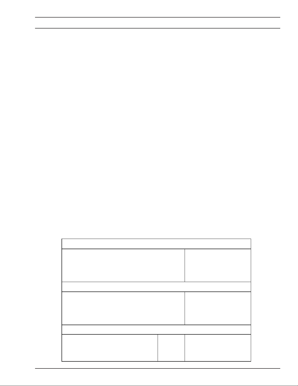
Table 1-1. Technical Specifications
RATED OUTPUT
60% Duty Cycle (3-phase input)
60% Duty Cycle (1-phase input)
100% Duty Cycle (3-phase input)
100% Duty Cycle (1-phase input)
Open-Circuit Voltage (max)
1.3 VOLT-AMPERE CURVES
Figure 1-2 illustrates the static volt-ampere characteristics for the power source in the MIG (CV), TIG (CC), and
Stick (CC) modes. The slant of these curves is referred
to as the 'slope' and is generally defined as the 'voltage
drop per 100 amperes of current rise'. These curves
show the output voltage available at any given output
current between the minimum and maximum settings of
the output control. Values for other settings fall between
300 A @ 32 V dc
225 A @ 29 V dc
225 A @ 29 V dc
200 A @ 28 V dc
72 V dc
PHYSICAL
Height
Width
Depth
Weight
INPUT VOLTAGE AND CURRENT @ RATED 60% DUTY CYCLE LOAD
230 (200-230)/460 (440) V ac models
575 V ac model
400 (380-415) V ac model
3-phase
1-phase
3-phase
3-phase
7
15 in. (380 mm)
10 in. (240 mm)
21 in. (530 mm)
87 lbs (39 kg)
38 (40-39)/21 (23) amps
48 (52-50)/32 (33) amps
17 amps
25 (26-24) amps

SECTION 1 DESCRIPTION
the minimum and maximum curves.
NOTE:
These measurements are made at the output terminals
of the power source. Additional voltage "drops" will
occur in the welding cable, torch cable, and in the
workpiece. The use of proper size welding cable and
secure electrical connections for the electrode and
ground circuits will minimize these effects which ad-
versely affect welding conditions and waste electrical
energy.
Figure 1-2. Volt-Ampere Characteristics and Duty Cycles
8

SECTION 2 INSTALLATION
2.1 GENERAL
This section provides detailed instructions for the proper
installation of the SVI 300i power source from initial
receipt of the equipment to output welding connections.
It is recommended that these instructions be followed
carefully to allow for the best possible operating environment.
2.2 REQUIRED TOOLS
Some procedures require use of the following tools:
5/16" wrench, 7/16" wrench, 5/16" allen wrench, and a
straight blade screwdriver. The use of socket wrenches
or nutdrivers are recommended over straight wrenches
due to the location of attaching hardware.
CORRECT
2.3 UNPACKING AND PLACEMENT
NOTE
When lifting the SVI 300i, apply direct upward pressure
to both of the carrying handles. Do not transport the SVI
300i with only one handle or apply outward pressure to
the handles. See Figure 2-1.
A. Immediately upon receipt of the SVI 300i,
inspect for damage which may have occurred
in transit. Notify the carrier of any defects or
damage at once.
B. After removing the components from the ship-
ping container(s), check the container for any
loose parts. Remove all packing materials.
WRONG!
Figure 2-1. Correct and Wrong Lifting Techniques
WRONG!
9

SECTION 2 INSTALLATION
C. Check air passages of power source for any
packing materials that may obstruct air flow
through the power source.
D. If the equipment is not to be installed immedi-
ately, store it in a clean, dry, well-ventilated
area.
E. The location of the power source should be
carefully selected to ensure satisfactory and
dependable service. Choose a location relatively close to a properly fused source of
electrical power.
F. The machine components are maintained at
proper operating temperatures by forced air
which is drawn through the cabinet by the fan
unit. For this reason, it is important that the
machine be located in an open area where air
can circulate freely at front and rear openings.
If space is at a premium, leave at least 1 foot
(300 mm) of clearance between the rear of the
power source and wall or other obstruction.
The area around the unit should be relatively
free of dust, fumes, and excessive heat. It is
also desirable to locate the unit so the cover
can be removed easily for cleaning and maintenance.
2.4 INPUT CONNECTIONS
internal components. If line voltage fluctuations exceed
this range, serious damage could occur. Therefore,
prior to installation, it is recommended that the line
voltage of the supply circuit be measured at several
times during the day. If fluctuations beyond the +/-10%
level are detected, another supply circuit should be
selected, or the local power company should be asked
to adjust the supply. In addition, certain types of factory
equipment can cause rapid voltage swings (transients)
which can cause the SVI 300i safety circuits to “trip”.
Examples of such equipment are resistance welders,
punch presses, and starting of large electric motors.
Should tripping by such transients become a problem,
ESAB has available a “Primary Line Conditioner” (P/N
15983) which can be added to filter out transient voltages. Contact your distributor for details. Please note
that the "conditioner" will not correct for sustained line
fluctuations which exceed the 10% limits of its rated
voltage inputs. If your input power cannot be maintained
within the 10% limits, consult your local power company
or contact the ESAB factory for possible solutions.
A. Input Terminal Board, U.S. Model (Figure
2-2). If you have 208- or 230-volt input power,
use the following procedure to modify your
input terminal board.
NOTE
Avoid dropping attaching hardware (screws, nuts,
washers) inside of the power source during the
following procedure. Parts left inside the power
source during operation may damage internal components.
ELECTRIC SHOCK CAN KILL! Precautionary measures should be taken to provide maximum protection against electrical shock.
Be sure that all power is OFF by opening the line
(wall) disconnect switch when primary electrical
connections are made to the power source.
To be doubly safe, check your input leads with a
voltmeter to make sure all power is OFF.
NOTE
As shipped from the factory, the SVI-300i, 230/460 V
version, is setup for 460 volts input. If you are using
the unit from a 230 V supply, modifications must be
made to the terminal board and at the ON-OFF
switch. The necessary modifications are described
in this section.
The SVI-300i is designed to compensate for line voltage
variations of plus or minus 10 percent from the rated
level while maintaining rated output, without damage to
1. Remove the 5/16" screw securing the access
panel on the right side of the power source.
2. Lift the panel and locate the input terminal
board.
3. Remove the set of nuts, flat washers, and
lockwashers securing each jumper and place
them in a safe place.
4. Re-position the jumpers as illustrated in figure
2-2 and secure them with the hardware removed in the previous step.
Note
Flat washers and lockwashers must ALWAYS be used
to secure the jumpers.
B. Input Power Cable (Figure 2-3). Before in-
stalling the power cable, make sure there is a
line (wall) disconnect switch with fuses or
circuit breakers at the main power panel. You
10

SECTION 2 INSTALLATION
NOTE
Avoid dropping attaching hardware (screws, nuts, washers) inside of the power source during the
following procedure. Parts left inside of the power source during operation may damage internal
components.
Figure 2-2. Input Power Terminal Board Connections (U.S. Model)
3-PHASE
BLACK
RED
WHITE
1-PHASE
(insulated)
BLACK
RED
To Customer's Fused Line Disconnect Switch (Main Input Power)
Power Leads (BLACK,RED & WHITE)
WHITE
Ground Lead (GREEN)
Figure 2-3. Input Power Cable Connections
11
SECTION 2 INSTALLATION
may either use the factory-installed input power
cable (No. 8 AWG, 4/c, type SO (90 °C), 12 ft
(3.7 m) length) or provide your own input
power leads. If you choose to provide your
own, make sure they are insulated copper
conductors. You must have two (single-phase)
or three (three-phase) power leads and one
ground wire. The wires may be heavy rubber
covered cable or may be run in a solid or
flexible conduit. Refer to Table 2-1 for recommended input conductors and line fuse sizes.
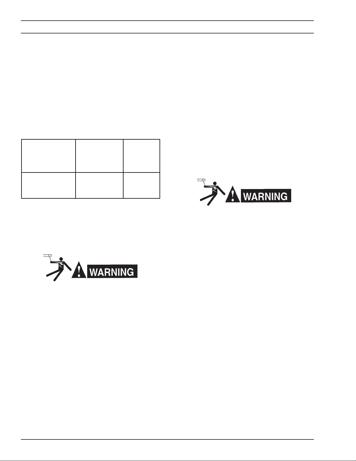
Table 2-1. Recommended Input Conductors and
Fuse Sizes
Rated Load
(3-phase input)
Volts Amps
208 40
230 38
460 21
* Sizes per National Electric Code for 90 °C rated copper conductors
@ 30 °C ambient. Not more than three conductors in raceway or cable.
Local codes should be followed if they specify larger sizes other than
those listed above.
Input &
Ground
Conductor*
CU/AWG (mm )
8 (10)
8 (10)
10 (6)
Time-Delay
Fuse Size
Amps
60
60
30
Use the following procedure to disconnect the factoryinstalled cable and connect your own input power leads/
cable.
4. Loosen the ON-OFF switch cable connections
(L1-L3) located inside the power source.
5. Remove the factory-installed power cable.
6. Thread your power leads/cable from the line
(wall) disconnect switch through the strain
relief hole in the rear panel of the power
source.
7. Attach the leads to the ON-OFF switch cable
connections as shown in figure 2-3 and secure tightly.
8. Tighten the strain relief and ground connection
securely.
9. Re-attach top cover with hardware removed in
step 1.
ELECTRIC SHOCK CAN KILL! Make sure the ground
lead is at least twice as long as the input power leads
on the inside of the power source (see Figure 2-3).
Ensure the strain relief and ground connection are
securely tightened.
If these conditions are not met, the power source
chassis may become electrically "hot" if excessive
stress is placed on the input power cable.
ELECTRIC SHOCK CAN KILL! It is of the utmost
importance that the chassis be connected to an
approved electrical ground to prevent accidental
shocking. Take care not to connect the ground wire
to any of the primary leads.
NOTE
Avoid dropping attaching hardware (screws, nuts,
washers) inside of the power source during the
following procedure. Parts left inside of the power
source during operation may damage internal components.
1. Remove the 5/16" screws securing the top
cover and place them in a safe place.
2. Remove the top cover and set aside.
3. Loosen the strain relief on the lower right-hand
corner of the rear panel.
If it is necessary to move the power source after it
has been connected to primary power, ensure that
the power source is turned OFF, and that an adequate amount of "slack" is maintained in the input
power cable.
If you have single-phase input power and are using the
factory-installed power cable, you must change the ONOFF switch cable connections from three-phase to
single-phase configuration as follows:
1. Remove the 5/16" screws securing the top
cover and place them in a safe place.
2. Remove the top cover and set aside.
3. Loosen the ON-OFF switch cable connection
L2 located inside the power source (see Figure 2-3).
4. Remove the red wire from cable connection
L2.
12
SECTION 2 INSTALLATION
Particular attention should be paid to the electrical
resistance in the welding circuit; especially, the work
and work cable and when using a water-cooled torch.
High resistance in the welding circuit can cause perfor-
ELECTRIC SHOCK CAN KILL! After the red wire has
been removed from L2, its center conductor is
exposed. This conductor must be covered with an
insulating material. Failure to do so properly could
cause a serious electrical shock hazard.
5. Re-attach the top cover with hardware removed in step 1.
2.4 OUTPUT CONNECTIONS
ELECTRIC SHOCK CAN KILL! Before making any
connections to the power source output terminals,
make sure that all primary power input power is
deenergized (OFF) at the line (wall) disconnect switch
or circuit breaker.
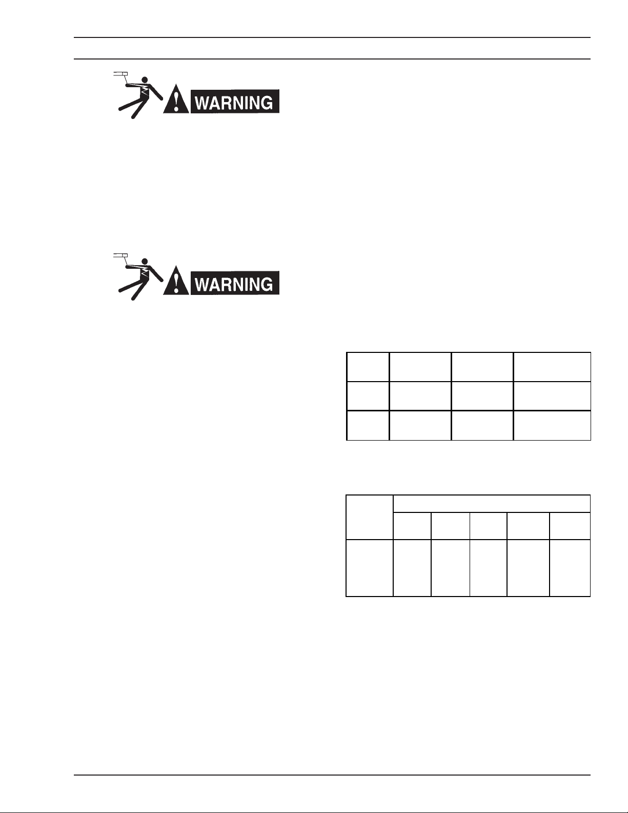
Two male plug connectors (P/N 13792513) are supplied
with the SVI 300i (see Figure 2-3). To assemble the
connectors onto each of your welding cables, refer to
the following instructions:
1. Slip the insulating boot over the end of the
cable.
2. Strip the wire approximately 1-1/2" (37 mm)
from the end.
3. Place the ferrule over the stripped wire end.
4. Place the male connector over the ferrule and
tighten the two Allen screws until they are
flush with the connector.
5. Slide the insulating boot over the assembly.
Refer to Tables 2-2 and 2-3 and Figures 2-4, 2-5, 2-6,
and 2-7 when attaching welding cables and optional
equipment to the SVI 300i.
mance deterioration (loss of "heat" input, popping of
weld puddle, bushy arcs, etc.). It is recommended that
the power source/wire feeder and workpiece be placed
as close together as possible to limit this resistance.
Make sure that the work cable (ground) is large enough,
kept as short as possible, properly insulated, securely
connected to the workpiece, and that all connections are
clean and tightly secured. If the work circuit includes
mechanical fixtures, ship structure, robot fixtures, etc.,
make sure that the circuit is secure and presents a low
resistance path to the flow of weld current. Also, the
power cable on a water-cooled torch is normally subject
to gradual deterioration and increasing resistance due
to corrosion which leads to the poor performance described above. To assure good torch performance, the
water-cooled power cable should be replaced periodically.
Table 2-2. Typical Output Connections
MIG Welding
(DCRP)
Electrode positive (+) negative (-)
Work negative (-) positive (+)
TIG Welding
(DCSP)
Stick Welding
(DCSP or DCRP)
positive (+) DCRP
negative (-) DCSP
negative (-) DCRP
positive (+) DCSP
Table 2-3. Recommended Welding
Cable Sizes - AWG (mm
Welding
Current
100
150
200
250
300
* Total cable length includes work and electrode cables. Cable size is based on direct
current, insulated copper conductors, 100% duty cycle, and a voltage drop of 4 or less
volts. The welding cable insulation must have a voltage rating that is high enough to
withstand the open circuit voltage of the machine.
** The supplied male output connectors will not accept anything smaller than #2 gauge (35
mm ) cable.
Total Length (Feet) of Cable in Welding Circuit*
50
(13 m)
6 (16)**
4 (25)**
3 (30)**
2 (35)
1 (50)
100
(25 m)
4 (25)**
3 (30)**
1 (50)
1/0 (50)
2/0 (70)
150
(38 m)
3 (30)**
1 (50)
1/0 (50)
2/0 (70)
3/0 (95)
2
)
200
(51 m)
2 (35)
1/0 (50)
2/0 (70)
3/0 (95)
4/0 (120)
250
(64 m)
1 (50)
2/0 (70)
3/0 (95)
4/0 (120)
4/0 (120)
13
SECTION 2 INSTALLATION
Figure 2-4. Male Output Connectors (P/N 13792513)
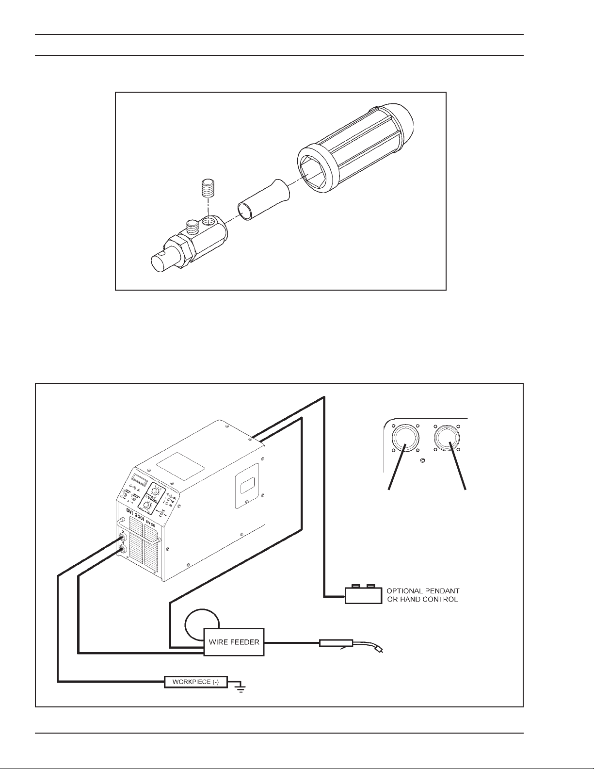
SVI 300i REAR VIEW
WIRE FEEDER -
accepts mating connector from both digital and
conventional wire feed-
-
ers.
REMOTE CONTROL accepts mating connectors from remote control accessories.
+
TORCH W/ SWITCH
Figure 2-5. MIG (GMAW) Interconnection Diagram
14

SECTION 2 INSTALLATION
SVI 300i REAR VIEW
REMOTE CONTROL -
accepts mating connectors from remote control accessories.
Figure 2-6. TIG (GTAW) Interconnection Diagram
SVI 300i REAR VIEW
REMOTE CONTROL -
accepts mating connectors from remote control accessories.
Figure 2-7. Stick (SMAW) Interconnection Diagram
15

SECTION 3 OPERATION
3.1 GENERAL
Never, under any circumstances, operate the power
source with the cover removed. In addition to the
safety hazard, improper cooling may cause damage
to internal components.
To prevent serious injury, never touch any torch
parts forward of the handle (nozzle, electrode, etc.)
unless the power switch is in the off position.
Wear proper protective gloves, clothing, safety
glasses, and helmet. A helmet with filter lens shade
No. 11-14 should provide adequate protection for
your eyes. Refer to the Safety Precautions in the
beginning of this manual for additional operating
precautions.
3.2 WELDING CONTROLS / INDICATORS
(Figure 3-1)
A. VOLTAGE/CURRENT- This potentiometer
sets and regulates the desired amount of
welding voltage/current required for your application. In constant voltage (CV) mode, voltage is controlled. In constant current (CC)
mode, current is controlled. The dial surround-
ing the knob provides a convenient reference
for resetting prior welding conditions. The
CONTROL switch must be in the PANEL
position for the VOLTAGE/CURRENT potentiometer to function.
B. MAIN POWER - This light will illuminate when
the PRIMARY POWER switch (located on the
rear panel) is placed in the ON position. This
rotary switch provides primary input power to
energize the control circuitry.
C. HI/LOW LINE- This light is "on" when the input
voltage is too high or too low. If a fault is
detected, the contactor will deenergize and
the power source will stop welding. Since this
condition can be caused by a transient voltage, try operating the torch switch again to
resume welding. If tripping continues, stop
and refer to section 5.
D. OVER TEMP- This light is "on" if components
in the power source overheat. If this happens,
allow the unit to cool with the primary power
switch in the ON position (the fan will help cool
the power source). Continue with welding only
when this light goes "off".
E. SLOPE- This 3-position switch sets the slope
of the volt-ampere curve characteristic in the
MIG (CV) mode. This control is bypassed in
the TIG and Stick modes. In MIG (GMAW)
welding, slope is particularly useful in short-
J
I
H
G
Figure 3-1. Controls / Indicators
16
A
F
B
C
D
E

SECTION 3 OPERATION
circuiting transfer (“short-arc”, “dip transfer”)
and for welding of aluminum. Slope adjustments control the short-circuit current and
reduce spatter during short-circuiting welding
of steel, and reduce the current fluctuations
which can cause instability when welding aluminum. Refer to Table 3-1 for available settings. Typical slope settings are shown on
Table 3-2 for several different electrode types,
shielding gases, and arc modes. For more
complete explanation of the function of slope,
refer to the “Mig Welding Handbook”, Part No.
791F18, or The Welding Handbook, published
by the American Welding Society.
Table 3-1. Slope Settings
Switch Position Process / Material Slope
FLAT
MEDIUM
STEEP
Spray Arc
Short Arc/MS/AL
Short Arc/MS/AL/SS
1 V / 100 A
3 V / 100 A
6 V / 100 A
F. INDUCTANCE/ARC FORCE- Arc penetra-
tion and wetting action are regulated by this
control when using the constant voltage mode.
Varying the inductance permits the operator
to optimize arc characteristics of short circuiting transfer. In general, increasing inductance will cause a “wetter,” more fluid puddle,
and lower the short circuiting frequency. Typical inductance settings are shown on Table 32 for several different electrode types, shielding gases, and arc modes. (As with SLOPE,
a more complete description of the function of
Inductance can be found in the “Mig Welding
Handbook”, Part No. 791F18, or The Welding
Handbook, published by the American Welding Society).
In the constant current mode (stick welding),
this control adjusts the rise in current as the
arc gets shorter. Thus, by increasing the ARC
FORCE setting, the electrode will penetrate
more deeply and operation will become somewhat more harsh, with increased spatter.
G. MIG/TIG/STICK- Weld process selection is
provided by this switch.
H. CONTACTOR- This switch determines the
location for contactor initiation. When placed
in the ON position, the contactor is closed and
welding voltage is available at the output receptacles. When placed in the REMOTE position, contactor closure is controlled by a
remote control device such as a wire feeder,
foot control, or hand pendant control.
I. CONTROL- This switch determines the loca-
tion from which welding voltage/current will be
regulated. In the PANEL position, full-range
voltage/current is controlled by setting the
VOLTAGE/CURRENT potentiometer on the
front panel. When MIG (CV) welding, this
PANEL position is used for conventional wire
feeders without voltage control capability. In
the REMOTE position, full range voltage/current control is regulated from a wire feeder
with voltage control capability (CV) or from a
remote control accessory (CC).
J. Digital Meter- This instrument provides direct
digital reading of open-circuit voltage, welding
voltage, or welding current depending on the
position of the VOLTS/AMPS selector switch.
3.3 MIG / GMAW (CV) Operation
A. Make all secondary output connections to the
power source output receptacles as described
in section 2 and as shown in the appropriate
wire feeder and/or control instruction literature.
B. After the primary input connections have been
made in accordance with section 2, close the
main wall disconnect switch or circuit breaker.
C. Place the primary power switch in the ON
position. This will apply power to the control
circuitry as indicated by the MAIN POWER
light on the front panel.
D. Place the CONTROL switch in the desired
position from which full-range welding voltage
will be regulated. Use the PANEL position for
control from the power source's front panel
(typical for conventional MIG wire feeders), or
the REMOTE position for remote voltage control wire feeders and/or accessories.
E. Place the CONTACTOR switch in the RE-
MOTE position.
F. Place the MIG/TIG/STICK switch in the MIG
position.
G. Set a wire feed speed and begin welding.
H. Depending on the position of the CONTROL
switch, set the appropriate VOLTAGE poten-
tiometer for your desired welding voltage.
17

SECTION 3 OPERATION
I. Set the INDUCTANCE potentiometer to pro-
vide the desired amount of inductance to suit
your MIG welding condition. Since excessive
inductance may impede arc starting, an initial
setting of "0" is recommended. Inductance
control is particularly effective and primarily
used in short circuiting arc applications.
NOTE
When the HC-5 remote hand control is plugged into the
power source, the INDUCTANCE potentiometer on the
power source is disabled even when the power source's
CONTROL switch is placed in the PANEL position.
J. Set the SLOPE switch to provide the desired
slope characteristic (FLAT, MEDIUM, or
STEEP) required for your operation. Refer to
Table 3-2 for recommended settings.
K. Commence welding operations by energizing
the torch switch.
L. For remaining wire feeder or control opera-
tions, refer to the appropriate instruction literature supplied with your particular system.
3.4 TIG / GTAW (CC) Operation
A. Make all secondary output connections to the
power source output receptacles as described
in section 2 and as shown in the appropriate
accessory instruction literature.
B. After the primary input connections have been
made in accordance with section 2, close the
main wall disconnect switch or circuit breaker.
C. Place the primary power switch in the ON
position. This will apply power to the control
circuitry as indicated by the MAIN POWER
light on the front panel.
ELECTRIC SHOCK CAN KILL! Make sure that the
contactor control switch on the remote control accessory is in the "off" position until you are ready to
weld. Otherwise, the electrode in the torch will be
"electrically-hot" and could shock you.
D. Place the CONTROL switch in the desired
position from which full-range welding current
will be regulated. Use the PANEL position for
control from the power source's front panel, or
the REMOTE position for control from a remote control accessory.
E. Place the CONTACTOR switch in the appro-
priate position. Use the PANEL position for
control from the power source's front panel, or
the REMOTE position for control from a remote control accessory.
F. Place the MIG/TIG/STICK switch in the TIG
position.
G. Ensure the power source's digital meter is set
to read AMPS.
H. Depending on the position of the CONTROL
switch, set the appropriate CURRENT potentiometer for your desired welding current.
NOTE
When the HC-5 remote hand control is plugged into the
power source, the ARC FORCE potentiometer (used for
stick welding) on the power source is disabled even
when the power source's CONTROL switch is placed in
the PANEL position.
J. Make sure you have a good clean ground and
a secure workpiece. Also, ensure that shielding gas is turned on and flowing. Refer to
Table 3-4 for recommended shielding gases.
K. To establish the welding arc, place the
CONTACTOR switch on the front panel or the
switch on the remote control or torch to the ON
position. This will energize the solid-state
contactor and provide welding power to the
torch/electrode. Touch the electrode to the
workpiece. When ready to weld, lift the torch
1/4" away from the workpiece. Welding current will automatically slope up to the preset
amount when the arc is established. Make
sure the CONTACTOR switch is turned "off"
after each weld is completed.
L. For remaining accessory operations, refer to
the appropriate instruction literature supplied
with your particular system.
18

SECTION 3 OPERATION
3.5 Stick / SMAW (CC) Operation
A. Make all secondary output connections to the
power source output receptacles as described
in section 2 and as shown in the appropriate
accessory instruction literature.
B. After the primary input connections have been
made in accordance with section 2, close the
main wall disconnect switch or circuit breaker.
C. Place the primary power switch in the ON
position. This will apply power to the control
circuitry as indicated by the MAIN POWER
light on the front panel.
ELECTRIC SHOCK CAN KILL! Make sure that the
contactor control switch on the remote control accessory is in the "off" position (until you are ready
to weld), otherwise, the electrode in the holder will
be "electrically-hot" and could shock you.
D. Place the CONTROL switch in the desired
position from which full-range welding current
will be regulated. Use the PANEL position for
control from the power source's front panel, or
the REMOTE position for control from a remote control accessory.
E. Depending on the position of the power source
CONTROL switch, place the CONTACTOR
switch in the ON or REMOTE position.
F. Place the MIG/TIG/STICK switch in the STICK
position.
G. Ensure the power source's digital meter is set
to read AMPS.
H. Set the ARC FORCE and CURRENT potenti-
ometers to "0".
I. Commence welding and adjust the CURRENT
and ARC FORCE potentiometers as required
for the stick electrode type and diameter being
used. Follow the electrode manufacturer's
recommendations.
J. Make sure the CONTACTOR switch is turned
OFF after each weld is completed.
K. For remaining accessory operations, refer to
the appropriate instruction literature supplied
with your system.
Table 3-2. Typical Slope and Inductance Settings (Constant Voltage Only)
Material Weld Process Arc Mode Shield Gas Slope Setting Inductance Setting
Carbon Steel
Carbon Steel
Carbon Steel
Carbon Steel
Carbon Steel
Stainless Steel
Stainless Steel
Stainless Steel
Aluminum
All Materials
MIG (GMAW)
MIG (GMAW)
MIG (GMAW)
Flux Cored (FCAW)
Flux Cored (FCAW)
MIG (GMAW)
MIG (GMAW)
Flux Cored (FCAW)
MIG (GMAW)
Pulsed MIG (GMAW-P)
Short Circuit
Short Circuit
Spray
Spray/Short
Spray/Short
Short Circuit
Spray
Spray
Spray
Pulse Spray
CO
Argon Mixes
Argon Mixes
Argon Mixes
Argon Mixes
Argon Mixes
Argon Mixes
2
CO
2
Tri-Mixes
All Gases
FLAT/MEDIUM
MEDIUM
FLAT
FLAT/MEDIUM
FLAT/MEDIUM
MEDIUM/STEEP
FLAT/MEDIUM
FLAT/MEDIUM
STEEP
STEEP
0-2
4-7
0-2
0-2
0-2
5-8
0-4
0-2
0-5
Not Applicable
19

SECTION 4 MAINTENANCE
4.1 GENERAL
If this equipment does not operate properly, stop work
immediately and investigate the cause of the malfunction. Maintenance work must be performed by an experienced person, and electrical work by a trained electrician. Do not permit untrained persons to inspect, clean,
or repair this equipment. Use only recommended replacement parts.
ELECTRIC SHOCK CAN KILL! Be sure that the line
(wall) disconnect switch or circuit breaker is open
before attempting any work inside the power source.
Always wear safety goggles with side shields when
blowing out the power source with air.
4.2 INSPECTION AND CLEANING
Since there are no moving parts (other than the fan) in
the power source, maintenance consist mainly of keeping the interior of the cabinet clean. Periodically, remove
the cover from the cabinet, and wearing proper eye
protection, blow accumulated dust and dirt from the air
passages and the interior components, using clean low
pressure air. It is imperative that the air passages, to the
interior of the unit, be free of dirt to ensure adequate
circulation of cooling air, especially over the rectifier
bridge plates. The length of time between cleaning will
depend on the location of the unit, and the amount of
dust in the atmosphere.
20

SECTION 5 TROUBLESHOOTING
5.1 GENERAL
5.2 FUNCTIONALITY CHECK (Table 5-1)
The SVI 300i Functionality Check should be used to
verify proper power source operation. Before performing the following checks, disconnect the remote connec-
ELECTRIC SHOCK CAN KILL! Before attempting
inspection or work inside the power source, be sure
that all primary power to the machine has been
tions (WIRE FEEDER and REMOTE CONTROL) from
rear of power source and make sure there is no load
attached to the output terminals.
externally disconnected and the line (wall) disconnect switch or circuit breaker is open.
Table 5-1. SVI 300i Functionality Check
1. Are input power supply connections properly secured? Go to next
2. Are the jumpers on the input terminal board proper ly configured and
secured?
3. If using 3-phase power, are all three primary leads securely connected to
primary powe r switch.
If using single-phase power, are black and white leads securely connected to
primary power switch?
4. Position power source controls as follows:
YES NO
step.
Go to next
step.
Go to next
step.
--- ---
Refer to
Section 2.
CONTACTOR - ON
VOLTS/AMPS - VO LT S
CONTROL - PANEL
MIG/TIG/STICK - STICK
CURRENT - "0"
ARC FORCE - "0"
SLOPE- Not Applicable in Stick mode.
5. Turn primary power switch to ON position. Does MAIN POWER light
illuminate?
6. Does digital m e ter show 0-2 volts? Go to next
7. Place CONTACTOR switch in the ON position. Does the fan energize? Go to next
8. Does digital m e ter show open circu it voltage? Go to next
9. Place CONTACTOR switch in the REMOTE position. Does digital meter
show 0-2 volts?
10. Short electrode to work table. Place the VOLTS/AMPS switch in the AMPS
position, and the CONTACTOR switch in the ON posi tion. Does digital me ter
show 8-15 amps?
11. Rotate ARC FORCE fully clockwise. Does digital meter show about 150
amps?
Go to next
step.
step.
step.
step.
Go to next
step.
Go to next
step.
Go to next
step.
Power source
faulty.
12. Rotate CURRENT fully clockwise. Does digital meter show about 300
amps?
SVI 300i has passed the functionality check. Problem may be in interconnection of gas lines or
polarity of output connectors. For technical assistance, refer to the Communication Guide located on
the last page of this manual.
Go to next
step.
21

SECTION 5 TROUBLESHOOTING
34919
22
Figure 5-1. Schematic Diagram - SVI 300i Power Source , 230/460 Vac
reflected in this schematic. For up-to-date information
on your model, refer to the schematic on the inside
cover of the power source or contact the factory.
NOTE: Recent modifications to the power source may not be

SECTION 5 TROUBLESHOOTING
34920-01
Figure 5-2. Wiring Diagram - SVI 300i Power Source , 230/460 Vac (Sheet 1 of 2)
23

SECTION 5 TROUBLESHOOTING
34920-02
Figure 5-2. Wiring Diagram - SVI 300i Power Source , 230/460 Vac (Sheet 2 of 2)
24

SECTION 6 REPLACEMENT PARTS
6.1 General
Replacement parts are illustrated on the following figures. When ordering replacement parts, order by part
number and part name, as listed.
Always provide the series or serial number of the unit on
which the parts will be used. The serial number is
stamped on the unit nameplate.
To assure proper operation, it is recommended that only
genuine ESAB parts and products be used with this
equipment. The use of non-ESAB parts may void your
warranty.
Replacement parts may be ordered from your distributor
or from:
ESAB Welding & Cutting Products
Attn: Customer Service Department
P.O. Box 100545
Ebenezer Road
Florence, SC 29401-0545
To order parts by phone, contact ESAB at (803) 6645540 or 4460. Orders may also be faxed to 1-800-634-
7548. Be sure to indicate any special shipping instructions when ordering replacement parts.
Refer to the Communication Guide located on the last
page of this manual for a list of customer service phone
numbers.
25

SECTION 6 REPLACEMENT PARTS
10,7
16, 17
13,14
12
11
9
15
1
2
3
4
ITEM
NO.
1
2
3
4
5
6
7
8
9
10
11
12
13
14
15
16
17
QTY
REQ.
1
1
1
1
2
2
5
1
1
3
1
1
2
2
1
2
2
5
6,7
8
Figure 6-1. SVI 300i Power Source
PART
NO.
34910
34927
954008
951814
951815
672831
2060170
32153
951824
673213
32156
951826
2062018
13730611
2091514
13733935
13792513
DESCRIPTION
COVER
DOOR, ACCESS
LABEL, HIGH VOLTAGE UNDER COVER
LAMP, IND, WHITE
LAMP, AMBER
SWITCH, ON-OFF-ON, SPDT
SEAL, SWITCH, BLACK
PANEL, FRONT
HANDLE
SWITCH, SPST
PANEL, CO NTROL
METER, LCD, 5 V
POTENTIOMETER, 10K OHM, 2 W
KNOB
LABEL, WARNING
RECEPTACLE, CABLE
CONNECTOR, QUICK (Not shown)
CIRCUIT
SYMBOL
PL1
PL2,3
S2,3
S4,5,6
DPM
R11,12
OTB
26

SECTION 6 REPLACEMENT PARTS
38
36,37
35
33,34
50
32
31,30
39
40,41
29,28
46
42,43
27
47
49
42,43
26,25
21
46
24
48
44
22
45
23
45
ITEM
NO.
21
22
23
24
25
26
27
28
29
30
31
32
33
34
35
36
37
38
39
40
41
42
43
44
45
46
47
48
49
50
QTY
REQ.
2
1
1
1
3
3
AR
2
2
2
2
1
1
1
1
1
1
1
2
4
4
2
2
2
2
2
1
1
2
3
Figure 6-2. SVI 300i Power Source (Left Side View)
PART
NO.
951190
38012
951819
17250110
951184
951189
77570003
17725005
951193
17750020
951194
99510975
951915
951192
17250005
951023
951196
34914
34901
17290225
951161
951799
951190
951237
674216
950516
23604891
951835
951940
950591
PAD, THERMAL, IGBT
PC BOARD, IGBT DRIVER
SHUNT, HALL EFFECT, 1 V, 100 A
RESISTOR, 100 OHM, 50 W
DIODE, MOD, FWD, 600 V, 100 A
PAD, THERMAL, DIODE, MOD
GROMMET, CONTINUOUS
RESISTOR, 5 OHM, 25 W
PAD, THERMAL, RES, 25 W
RESISTOR, 20 OHM, 50 W
PAD, THERMAL, RES, 50 W
LABEL, GROUND
DIODE, MOD, 3-PHASE, BRIDG E
PAD, THERMAL, BRIDGE
RESISTOR, 5 OHM, 50 W
DIODE, 1200 V, 70 A
PAD, THERMAL, SCR, MOD
HEAT SINK
TRANSFORMER, CURRENT, 20 mH
RESISTOR, 2.5K OHM, 20 W
CAPACITOR, 20 µF, 400 VDC
IGBT, MOD, 600 V, 150 A
PAD, THERMAL, IGBT
CAPACITOR, .047 µF, 400 V DC
CAPACITOR, .02µF, 1K V
CAPACITOR, .05 µF, 600 V
LABEL, DANGER HIGH VOLTAGE
SWITCH, THERMAL
CAPACITOR 1µF 600V
METAL OXIDE VARISTOR
DESCRIPTION
CIRCUIT
SYMBOL
PCB3
PCB2 (SH1)
R5
D1,2,3
R9,10
R4,8
BR1
R1
SCR1
T3,4
R2,3,6,7
C2,3,6,7
Q1,2
C4,8
C11,12
C9,10
TS1
C13, 14
MOV 1, 2, 3
27
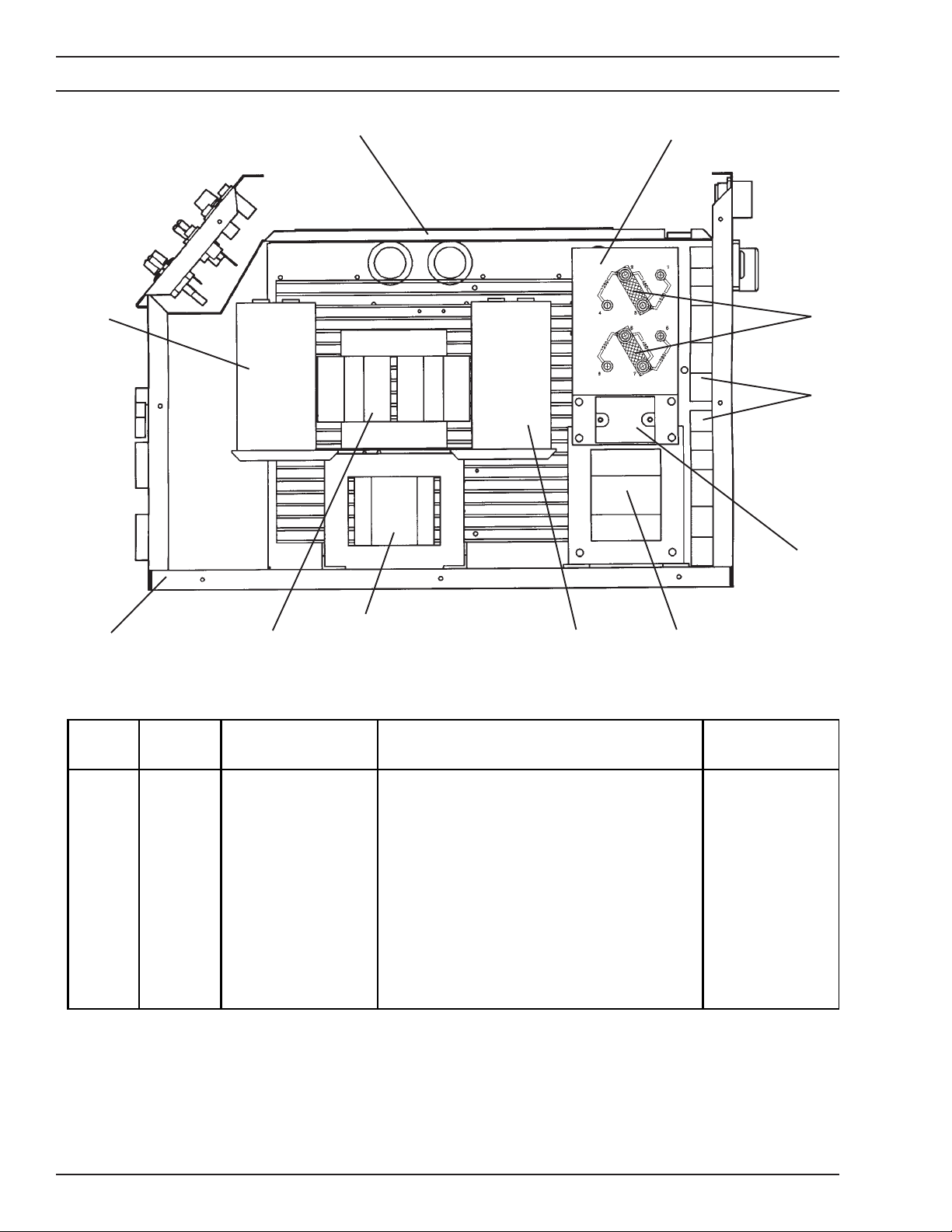
SECTION 6 REPLACEMENT PARTS
60
61,62
51
52
53
54
59
ITEM
NO.
51
52
53
54
55
56
57
58
59
60
61
62
QTY
REQ.
1
4
2
1
1
1
1
1
1
1
1
10
58
57
Figure 6-3. SVI 300i Power Source (Right Side View)
56
PART
NO.
34922
672065
951816
951818
34875
951635
34880
34881
34908
951635
38004
950708
BOARD, TERMINAL ASSY
STRAP, TERMINAL
FAN, 230 V, 50/60 Hz, 260 CFM
RELAY, SOLID STATE, 25 A
TRANSFORMER, CONTROL
CAPACITOR, 1900 µF, 450 VDC
INDUCTOR ASSY
TRANSFORMER, MAIN
BASE
CAPACITOR, 1900 µF, 450 VDC
PC BOARD, CONT ROL
SUPPORT, PC BOARD
DESCRIPTION
55
CIRCUIT
SYMBOL
TB1
M1,2
K1
T2
C5
L1
T1
C1
PCB1
28
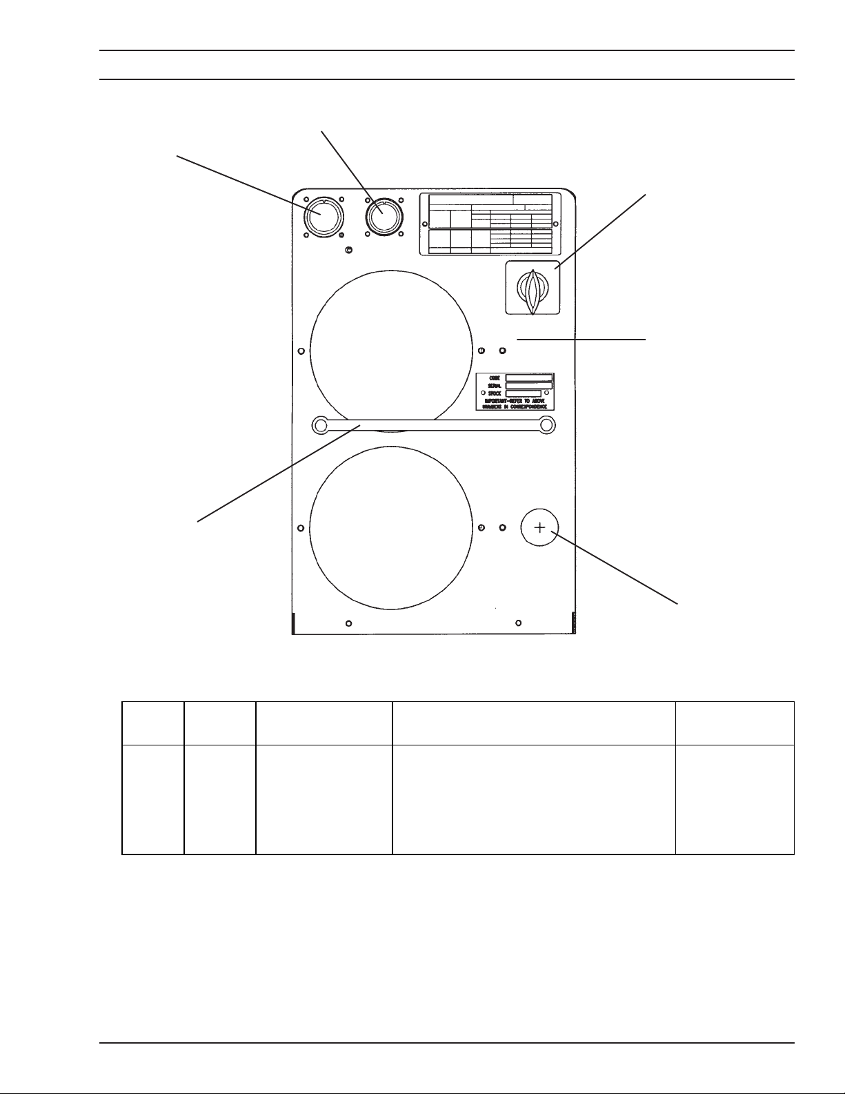
SECTION 6 REPLACEMENT PARTS
76
75
71
72
ITEM
NO.
71
72
73
74
75
76
74
QTY
REQ.
1
1
1
1
1
1
Figure 6-4. SVI 300i Power Source (Rear View)
PART
NO.
951817
32155
97W63
951824
951822
951823
SWITCH, POWER, DISC, 600 V, 30 A
PANEL, REAR
STRAIN RELIEF
HANDLE
RECEPTACLE ASSY, 19-PIN
RECEPTACLE ASSY, 14-PIN
DESCRIPTION
73
CIRCUIT
SYMBOL
S1
J1
J2
29

SECTION 6 REPLACEMENT PARTS
6.2 Spare Parts
Table 6-1 lists recommended spare parts for a 2-year
functional period.
Table 6-1. Recommended Spare Parts List
PART
NO.
38004 1
38012 1
672065 4
672831 2
673213 3
951023 1
951184 3
951207 1
951515 1
951635 2
951814 1
951815 2
951816 2
951817 1
951818 1
951819 1
951824 2
QTY. PER
UNIT
DESCRIPTION
PC BOARD, CONTROL
PC BOARD, IGBT DRIVER
STRAP, TERMINAL
SWITCH, TOGGLE, SPDT, 3-POS, 15 A, 125 V, SPD
SWITCH, TOGGLE, SPST, 2-POS, 15 A, 125 V, Q/D
RECTIFIER, SIL CON, 70 A, 1200 V
DIODE MODULE, FRD, 100 A, 600 V
BRIDGE, 3-PHASE, 1200 V, 75 A
CAPACITOR, .047 µF, 660 V AC
CAPACITOR, ALUMINUM, 1900 µF, 450 V DC
LIGHT, INCAND, 12 V
LIGHT, INCAND, 12 V
FAN, 230 V, 50/60 Hz
SWITCH, PWR, DISC, 3-PHASE, 600 V, 30 A
RELAY, SS, 3-32 V DC / 24-280 V AC, 25 A
SENSOR, CURRENT, HALL
HANDLE, ALUMINUM, .50 X 8.00
Spare parts should be ordered as described in section 6,
paragraph 6.1.
RECOMMENDED ON-HAND QUANTITY PER
SPECIFIED NUMBER OF UNITS TO MAINTAIN
1-10
UNITS
1 2 4 8
11-25
UNITS
1 1 1
3 3 3
2 2 2
1 1 2
1 1 2
1 1 2
26-50
UNITS
1 1
1 1
1 1
1 1
1 1
1 1
1 1
1 1
1 1
51-100
UNITS
1
951825 2
951826 1
2062018 2
13730611 2
13733935 2
13792513 2
17250005 1
17250110 1
17725005 2
17750020 4
2060170 5
MODULE, IGBT, 600 V, 140 A
METER, LCD, 5 V DC, 3
POTENTIOMETER, 10 K OHM, 2 W
KNOB
PANEL RECEPTACLE, 2-1/0
ADAPTOR
RESISTOR, WW, FIXED, ST, 50 W, 5%, 5.00
RESISTOR, WW, FIXED, ST, 50 W, 5%, 100.00
RESISTOR, WW, AHNI, TT, 25 W, 3%, 5.00
RESISTOR, 20 OHM, 50 W, 3%, NON-INDUCT
SEAL, SWITCH, BLACK
30
2 2 2
1 1
1 1 2
1 1 2
1 1 2
1 2 4 8
1 1 2 4
1 1
1 1
1 1 2
2 4 8 15

ESAB Welding & Cutting Products, Florence, SC Welding Equipment
COMMUNICATION GUIDE - CUSTOMER SERVICES
A. CUSTOMER SERVICE QUESTIONS: Telephone: (800)362-7080 / Fax: (800) 634-7548
Order Entry Product Availability Pricing Delivery
Order Changes Saleable Goods Returns Shipping Information
B. ENGINEERING SERVICE: Telephone: (843) 664-4416 / Fax : (800) 446-5693
Welding Equipment Troubleshooting Hours: 7:30 AM to 5:00 PM EST
Warranty Returns Authorized Repair Stations
C. TECHNICAL SERVICE: Telephone: (800) ESAB-123/ Fax: (843) 664-4452
Part Numbers Technical Applications Hours: 8:00 AM to 5:00 PM EST
Performance Features Technical Specifications Equipment Recommendations
D. LITERATURE REQUESTS: Telephone: (843) 664-5562 / Fax: (843) 664-5548
E. WELDING EQUIPMENT REPAIRS: Telephone: (843) 664-4487 / Fax: (843) 664-5557
Repair Estimates Repair Status Hours: 7:30 AM to 3:30 PM EST
F. WELDING EQUIPMENT TRAINING:
Telephone: (843)664-4428 / Fax: (843) 679-5864
Training School Information and Registrations Hours: 7:30 AM to 4:00 PM EST
G. WELDING PROCESS ASSISTANCE:
Telephone: (800) ESAB-123 Hours: 7:30 AM to 4:00 PM EST
H. TECHNICAL ASST. CONSUMABLES:
Telephone : (800) 933-7070 Hours: 7:30 AM to 5:00 PM EST
Hours: 8:00 AM to 7:00 PM EST
Hours: 7:30 AM to 4:00 PM EST
F15-183-A 200210
IF YOU DO NOT KNOW WHOM TO CALL
Telephone: (800) ESAB-123/ Fax: (843) 664-4452/ Web:http://www.esab.com
Hours: 7:30 AM to 5:00 PM EST
 Loading...