


A25 STA / A25 STB
101103105107109111102021110025108024042106023061104022041100020040060001
Bruksanvisning
Brugsanvisning
Bruksanvisning
Käyttöohjeet
Instruction manual
Betriebsanweisung
Manuel d’instructions
Gebruiksaanwijzing
Instrucciones de uso
Istruzioni per l’uso
Manual de instruções
ПдзгЯет чсЮуещт
Valid for Serial NO 751, 8380443 922 001 060512

SVENSKA 3..............................................
DANSK 14................................................
NORSK 25................................................
SUOMI 36................................................
ENGLISH 47..............................................
DEUTSCH 58.............................................
FRANÇAIS 69.............................................
NEDERLANDS 80.........................................
ESPAÑOL 91..............................................
ITALIANO 102..............................................
PORTUGUÊS 113..........................................
ЕЛЛЗНЙКБ 124.............................................
Rätt till ändring av specifikationer utan avisering förbehålles.
Ret til ændring af specifikationer uden varsel forbeholdes.
Rett til å endre spesifikasjoner uten varsel forbeholdes.
Oikeudet muutoksiin pidätetään.
Rights reserved to alter specifications without notice.
Änderungen vorbehalten.
Sous réserve de modifications sans avis préalable.
Recht op wijzigingen zonder voorafgaande mededeling voorbehouden.
Reservado el derecho de cambiar las especificaciones sin previo aviso.
Ci riserviamo il diritto di variare le specifiche senza preavviso.
Reservamo--nos o direito de alterar as especificações sem aviso prévio.
ДйбфзсеЯфбй фп дйкбЯщмб фспрпрпЯзузт рспдйбгсбцюн ЧщсЯт рспейдпрпЯзуз.
-- 2 --

ENGLISH
1 DIRECTIVE 48........................................................
2SAFETY 48...........................................................
3 INTRODUCTION 49...................................................
3.1 Equipment 50................................................................
4 INSTALLATION 54....................................................
4.1 Connection of Welding Station A25 STA to welding power source LTP 450 55........
5 OPERATION 55.......................................................
5.1 Settings 55..................................................................
5.2 Welding start 56..............................................................
6 MAINTENANCE 56....................................................
6.1 Maintenance and Service 56...................................................
7 ACCESSORIES 56....................................................
8 ORDERING OF SPARE PARTS 57......................................
DIAGRAM 136............................................................
SPARE PARTS LIST 137...................................................
TOCe
-- 4 7 --

GB
1 DIRECTIVE
DECLARATION OF CONFORMITY
Esab Welding Equipment AB, 695 81 Laxå, Sweden, gives its unreserved guarantee
that automatic welding machine A25 STA / A25 STB from serial number 751 complies with standard EN 60292, in accordance with the requirements of directive
(89/392/EEA) and addendum and standard EN 50199 in accordance with the requirements of directive 89/336/ EEA and addendum 93/68/ EEA .
-- -- -- -- -- -- -- -- -- -- -- -- -- -- -- -- -- -- -- -- -- -- -- -- -- -- -- -- -- -- -- -- -- -- -- -- -- -- -- -- -- -- -- -- -- -- -- -- -- -- -- -- -- -- -- -- -- -- -- -- -- -- -- --------
Laxå 98--01--05
Paul Karlsson
Managing Director
Esab Welding Equipment AB
695 81 LAXÅ
SWEDEN Tel: + 46 584 81000 Fax: + 46 584 12336
2SAFETY
Users of ESAB welding equipment have the ultimate responsibility for ensuring that anyone who
works on or near the equipment observes all the relevant safety precautions. Safety precautions
must meet the requirements that apply to this type of welding equipment. The following recommendations should be observed in addition to the standard regulations that apply to the workplace.
All work must be carried out by trained personnel well--acquainted with the operation of the welding
equipment. Incorrect operation of the equipment may lead to hazardous situations which can result
in injury to the operator and damage to the equipment.
1. Anyone who uses the welding equipment must be familiar with:
S its operation
S location of emergency stops
S its function
S relevant safety precautions
S welding
2. The operator must ensure that:
S no unauthorised person is stationed within the working area of the equipment when it is
started up.
S no--one is unprotected when the arc is struck
3. The workplace must:
S be suitable for the purpose
S be free from draughts
4. Personal safety equipment
S Always wear recommended personal safety equipment, such as safety glasses, flame--proof
clothing, safety gloves.
S Do not wear loose--fitting items, such as scarves, bracelets, rings, etc., which could become
trapped or cause burns.
5. General precautions
S Make sure the return cable is connected securely.
S Work on high voltage equipment may only be carried out by a qualified electrician.
S Appropriate fire extinquishing equipment must be clearly marked and close at hand.
S Lubrication and maintenance must not be carried out on the equipment during operation.
dta2d1ea
-- 4 8 --
GB
WARNING
ARC WELDING AND CUTTING CAN BE INJURIOUS TO YOURSELF AND OTHERS. TAKE PRECAUTIONS WHEN WELDING. ASK FOR YOUR EMPLOYER’S SAFETY PRACTICES WHICH SHOULD BE
BASED ON MANUFACTURERS’ HAZARD DATA.
ELECTRIC SHOCK -- Can kill
S Install and earth the welding unit in accordance with applicable standards.
S Do not touch live electrical parts or electrodes with bare skin, wet gloves or wet clothing.
S Insulate yourself from earth and the workpiece.
S Ensure your working stance is safe.
FUMES AND GASES -- Can be dangerous to health
S Keep your head out of the fumes.
S Use ventilation, extraction at the arc, or both, to take fumes and gases away from your breathing zone
and the general area.
ARC RAYS -- Can injure eyes and burn skin.
S Protect your eyes and body. Use the correct welding screen and filter lens and wear protective
clothing.
S Protect bystanders with suitable screens or curtains.
FIRE HAZARD
S Sparks (spatter) can cause fire. Make sure therefore that there are no inflammable materials nearby.
NOISE -- Excessive noise can damage hearing
S Protect your ears. Use earmuffs or other hearing protection.
S Warn bystanders of the risk.
MALFUNCTION -- Call for expert assistance in the event of malfunction.
READ AND UNDERSTAND THE INSTRUCTION MANUAL BEFORE INSTALLING OR OPERATING.
PROTECT YOURSELF AND OTHERS!
3 INTRODUCTION
A25 is a modular component system for mechanised TIG welding. The components
can be built together for customised solutions and are contained in the STA/STB automatic tube welding machines and welding station STA.
Typical applications for A25:
S Automatic tube welding machines
S Welding column and booms
S Head and tailstocks
S Tables for circumferential welding
S Fixtures for longitudinal welding
S Customised applications
Welding station A25 STA
The A25 STA welding station is designed for longitudinal welding of tubes and for
welding of tube joints or other types of workpieces.
For rotation of the workpiece the station is provided with a motorised turntable.
Automatic tube welding machines A25 STA / A25 STB
A25 STA/ A25 STB are automatic welding machines designed for longitudinal welding of tubes and for welding of tube joints. They are to be used together with some
type of carrier, for example a column and boom unit or a railborne carriage.
dta2d1ea
-- 4 9 --
GB
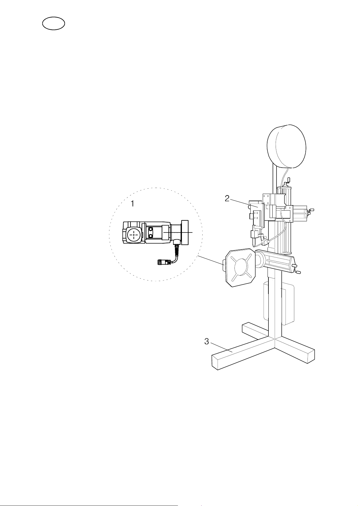
3.1 Equipment
3.1.1 Welding station A25 STA
Welding station A25 STA is equipped with a motorised AVC slide, a motorised
weaving slide and a VEC motor for the rotation of the workpiece.
The station can also be provided with equipment for narrow--gap welding. The
welding station is adapted for connection to the programmable welding power source
LTP 450.
3.1.2 Main components -- welding station A25 STA:
1. VEC motor with gear
2. Automatic tube welding machine A25 STA with machine torch
BTE 250M (design 0443 911 882)
Automatic tube welding machine A25 STA with machine torch
BTE 500M (design 0443 911 883)
3. Stand
dta2d1ea
-- 5 0 --
GB
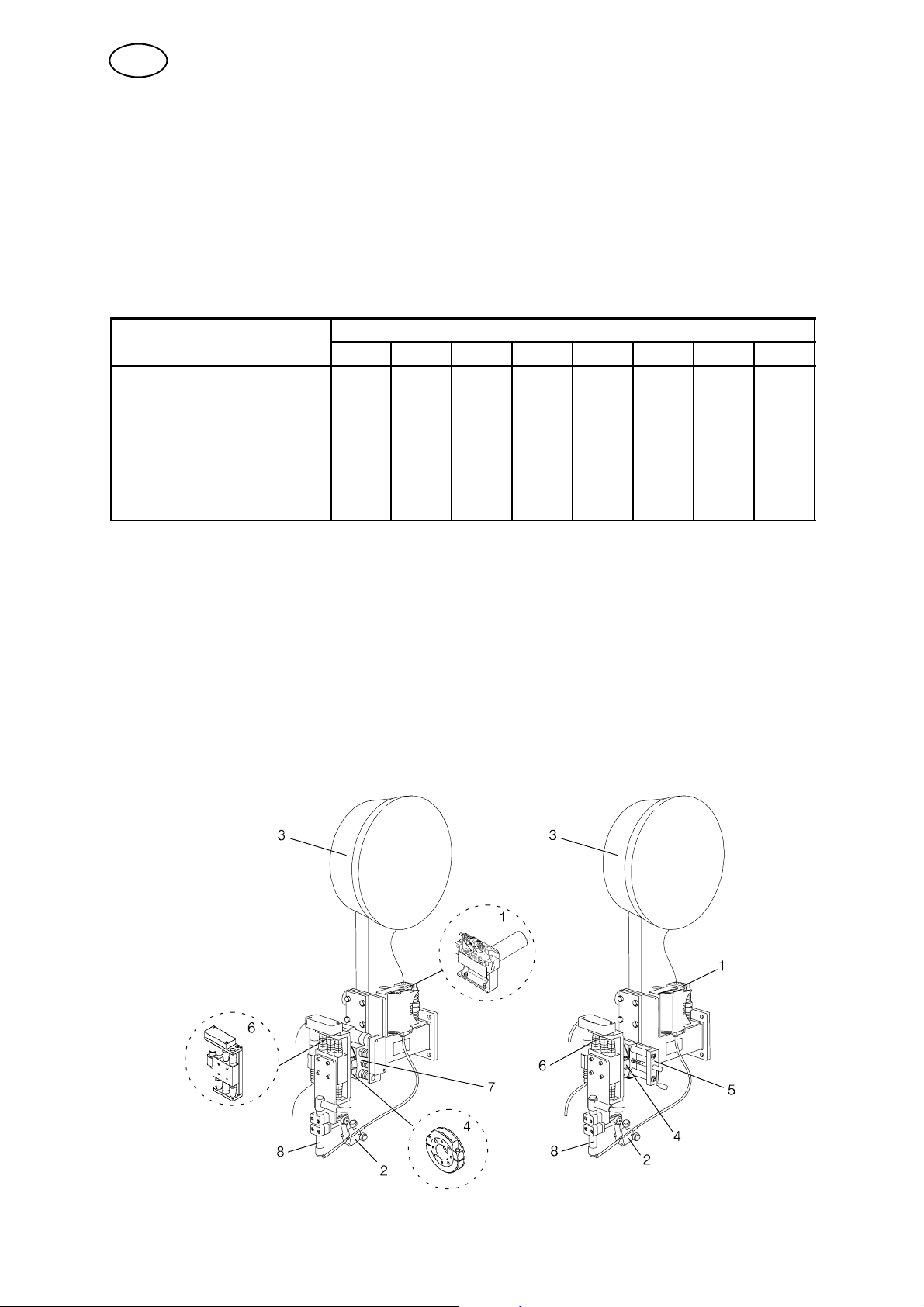
3.1.3 Automatic tube welding machine A25 STA
The automatic tube welding machines are provided with a motor--driven AVC slide,
and depending on the design, a motor--driven weaving slide or a manual horizontal
slide.
The station can also be provided with equipment for narrow--gap welding of material
up to 80 mm thickness.
The automatic tube welding machines are adapted for connection to the
programmable welding power source LTP 450.
The automatic tube welding machine A25 STA is available in the following designs:
Order number: 0443 911
Design: 880 881 882 883 884 885 886 887
Machine torch BTE 250M X X X X
Machine torch BTE 500M X X X X
Motor--driven AVC slide X X X X X X
Motor--driven weaving slide X X
Manual horizontal slide X X X X
Manual vertikal slide X X
3.1.4 Main parts -- au to matic tube welding machine A25 STA (see page 53):
1. Wire feed unit
2. Wire guide unit
3. Wire bobbin
4. Circular slide
5. Manual horizontal slide (for designs 884 and 885)
6. Motor--driven AVC slide
7. Motor--driven weaving slide (for designs 882 and 883)
8. Machine torch BTE 250M (for designs 880, 882 and 884)
Machine torch BTE 500M (for designs 881, 883 and 885)
dta2d1ea
-- 5 1 --

GB
3.1.5 Automatic tube welding machine A25 STB
The automatic tube welding machines are provided with manually adjustable slides
with gas spring. The spring can easily be dismounted, if desired.
The slides are adapted for connection to the programmable welding power source
LTS 320 or LTP 450.
The automatic tube welding machine A25 STB is available in the following designs:
Order number: 0443 912
Design: 880 881
Machine torch BTE 250M X
Machine torch BTE 500M X
Slide with gas spring X X
3.1.6 Main parts -- Auto matic tube welding machine A25 STB (see page 53):
1. Wire feed unit
2. Wire guide unit
3. Wire bobbin
4. Circular slide
5. Slide with gas spring
6. Guide wheel device
7. Machine torch BTE 250M (for design 880)
Machine torch BTE 500M (for design 881)
dta2d1ea
-- 5 2 --

GB
Main parts description:
S The wire feed unit is designed for the wire dimensions 0.6 -- 0.8 -- 1.0 -- 1.2 --
1.6 mm.
The drive roller for 1.6 mm is only supplied together with machine torch BTE
500M.
Technical data:
Motor voltage (DC) 48 V
Armature rotation speed 70 -- 5500 r/min
Gear ratio 159:1
Max. power 50 W
Wire feed speed 0.1 -- 2.6 m/min
S The wire guide unit is play--free and is provided with two setting screws for the
adjustment of the filler wire position +/-- 4 mm in each direction.
The centre tube is axially adjustable and is secured by way of a stop screw.
Nozzles are available for the wire dimensions 0.6 -- 0.8 -- 1.0 -- 1.2 -- 1.6 mm.
S Themax.diameterofthewire bobbin is 300 mm and the weight max. 15 kg.
S Slides
S The circular slide permits optional setting of the angle for fillet welding.
S The setting length of the manual horizontal slide is 93 mm.
S The motor--driven AVC slide and the motor--driven weaving slide are
fitted with a ball screw, driven by a toothed belt over a DC motor.
The motor is connected by way of an 8 m screened cable.
Technical data:
Motor--driven A VC slide Motor--driven weaving slide
Setting length 76 mm 76 mm
Motor voltage (DC) 12 V 48 V
Armature rotation speed 100 -- 8000 r/min 70 -- 5500 r/min
Gear ratio 159:1 14:1
Control speed max. 2.81 mm/s max. 19 mm/s
S Slide with gas spring -- the power of the spring is 40 N.
For fillet welding a slide cross with two gas springs is used. One of the
springs can be dismounted, and a free runner adapted as a cross slide is
obtained.
The setting length of the slide is 76 mm.
S The guide wheel device is provided with two setting screws for vertical and
lateral adjustment of the tungsten electrode in the weld joint.
The lateral adjustment is +/-- 3 mm.
The guide wheel device can be used for butt and fillet welding. For the guide
wheel to be used for joint tracking in butt welding, a gap of about 0.5 mm is
required between the workpieces.
Two types of gu id e wheels are available:
S Guide wheel with pointed tread for butt welding.
S Guide wheel with rounded tread for fillet welding.
dta2d1ea
-- 5 3 --
GB
The guide wheel device can be combined with the wire guide unit.
Using this combination the filler wire must be fed in slantwise from the front.
S The machine torches BTE 250M and BTE 500M are water--cooled and
designed for welding with up to 250 A and 500 A welding current.
S The VEC motor with gear is a separately magnetised DC motor with a
combined gear/worm gear (see instruction manual 0443 393 xxx).
To the VEC motor with gear belong a terminal box and 2 connection cables
(rotation and CAN/42V).
Fit the 4 supplied insulators on the terminal box to avoid that the casing of the
box gets into electrical contact with earth.
Technical data:
Voltage (DC) 42 V
Gear ratio 672:1
Max. permissible torque 50 Nm
Rotation speed 1000 r/min
Output power at rated voltage 36 W
4 INSTALLATION
The installation must be executed by a professional.
WARNING!
Rotating parts can cause injury, take great care.
WARNING -- TIPPING RISK!
Fasten the equipment -- particularly if the ground is uneven or sloping.
S Welding power source LTP 450, see instruction manual 0456 634 xxx.
S VEC motor with gear, see instruction manual 0443 393 xxx.
S Machine torches BTE 250M, BTE 500M, see instruction manual 0443 424 xxx.
dta2d1ea
-- 5 4 --
GB
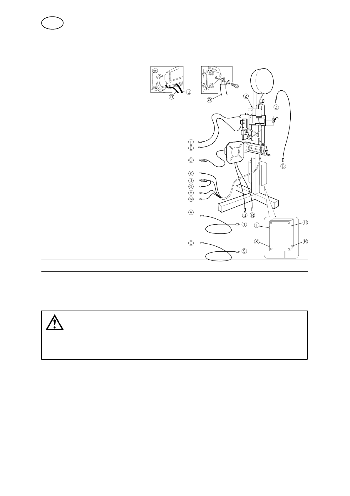
4.1 Connection of Welding Station A25 STA to welding power
source LTP 450
B--B Motor cable -- wire feed
C--C Motor cable -- rotation
E--E Motor cable -- AVC unit
F--F Motor cable -- weaving unit
G--G Cooling water hose, in
H--H Cooling water hose, out
J--J Welding cable
K--K Measuring cable
M--M Gas hose, out
Q--Q Return cable +
R--R Connection cable -- pulse generator VEC
S--S Motor cable -- rotation
T--T Connection cable -- CAN 42V
U--U Connection cable -- armature VEC
V--V Connection cable -- CAN 42 V
Z--Z Motor cable -- wire feed
5 OPERATION
General safety regulations for the handling of the equipment can be found on
page 48. Read through before you start using the equipment!
S Welding power source LTP 450, see programming manual 0456 638 xxx.
WARNING!
To avoid the welding tool being damaged, check that the return cable is connected to the
workpiece and that the tungsten electrode is in the start position before the welding commences.
5.1 Settings
S Make sure that all gas hoses, return and connection cables are properly fitted.
S Make sure that a correctly ground thorium or tungsten electrode is fitted in the
machine torch.
dta2d1ea
-- 5 5 --

GB
5.2 Welding start
S Recall the welding program to be used to the working
area (see the programming manual)
S Press the start button (A) on the control unit.
6 MAINTENANCE
Note:
All warranty undertakings given by the supplier cease to apply if the customer
attempts to rectify any faults on the machine during the warranty period.
6.1 Maintenance and Service
S Keep the movable parts of the automatic welding machine free of dust and dirt.
As necessary, clean the machine using dry compressed air (reduced pressure).
S Check that all screws and nuts are tightened.
S Check that all cables and hoses are undamaged and properly connected.
S Clean and grease the slides as necessary using Molycote.
7 ACCESSORIES
Special nozzle for narrow--gap welding 0441 667 880..........................
Wire guide unit for narrow--gap welding 0441 407 882.........................
Beam--travelling carriage 0458 002 880......................................
dta2d1ea
-- 5 6 --

GB
8 ORDERING OF SPARE PARTS
A25 STA / A25 STB is designed and tested in accordance with the EN 60292
(IEC 292) international standard.
It is the obligation of the service unit which has carried out the service or repair work to make sure that the product still conforms to the said standard.
Spare parts are ordered through your nearest ESAB representative, see back cover.
When ordering spare parts, please state machine type and number as well as designation and spare part number as shown in the spare parts list.
This will simplify dispatch and ensure you get the right part.
dta2d1ea
-- 5 7 --
 Loading...