


April 2007
Installation, Operation, and Maintenance for the
SmartFlow 2.5
Plasma System Plumbing Box
F-15-732

The equipment described in this manual is
potentially hazardous. Use caution when
installing, operating and maintaining this
equipment.
Purchaser is solely responsible for the safe
operation and use of all products purchased,
including compliance with OSHA and other
government standards. ESAB Cutting
Systems has no liability for personal injury or
other damage arising out of the use of any
product manufactured or sold be ESAB. See
standard ESAB terms and conditions of sale
for a specific statement of ESAB’s
responsibilities and limitations on its liability.
ESAB Cutting Systems first priority is total
customer satisfaction. We constantly look for
ways to improve our products, service and
documentation. As a result, we make
enhancements and/or design changes as
required. ESAB makes every possible effort to
ensure our documentation is current. We
cannot guarantee that each piece of
documentation received by our customers
reflects the latest design enhancements.
Therefore, the information contained in this
document is subject to change without notice.
This manual is ESAB Part Number F15732
This manual is for the convenience and use of the
cutting machine purchaser. It is not a contract or
other obligation on the part of ESAB Cutting
Systems.
© ESAB Cutting Systems, 2003 ,2004
All rights reserved
Printed in U.S.A.

Table Of Contents
Safety (Section 1)
1.1 Introduction.........................................................................................................1-1
1.2 Safety Notations And Symbols...........................................................................1-2
1.3 General Safety Information.................................................................................1-3
1.4 Installation Precautions ......................................................................................1-4
1.5 Electrical Grounding...........................................................................................1-5
1.6 Operating A Plasma Cutting Machine ................................................................1-6
1.8 Safety References............................................................................................1-13
1.8.1 USA Domestic............................................................................................1-14
1.8.2 International ...............................................................................................1-15
Description (Section 2)
2.1 Introduction.........................................................................................................2-1
2.2 SmartFlow II
2.3 SmartFlow II
2.4 SmartFlow II
2.5 Gas Requirements..............................................................................................2-2
2.6 Water Supply Requirements...............................................................................2-3
2.7 Electrical Input Requirements.............................................................................2-3
2.8 Dimensions.........................................................................................................2-4
V
and PT-15XL................................................................................2-1
V
and PT-19XLS/PT-600.................................................................2-2
V
Options ........................................................................................2-2
Installation (Section 3)
3.1 Introduction.........................................................................................................3-1
3.2 Box Mounting (Bottom View)..............................................................................3-1
3.3 Hose and Cable Connections.............................................................................3-2
3.3.1 Starter Box Connections..............................................................................3-4
3.3.2 PC Board Connections.................................................................................3-5
3.3.3 Torch Cooling Water Connections...............................................................3-6
3.3.4 Power Source To SMF II
3.4 Nomex Insulation................................................................................................3-8
3.5 Gas Connections................................................................................................3-8
3.5.1 Gas Lines From Supply................................................................................3-8
3.5.2 Gas Pressure Setup...................................................................................3-10
3.6 Cut Water Setup (PT-15XL) .............................................................................3-10
3.7 Secondary Shield Gas Setup (PT-19XLS/PT-600)...........................................3-11
3.8 A Component Relationship Block Diagram ......................................................3-12
3.9 Fluid Schematic – SmartFlow II
V
Buss Connection................................................3-7
V
Standard and H-35 Versions........................3-14
SmartFlow 2.5

Table Of Contents
Operation (Section 4)
4.1 Operation Introduction........................................................................................4-1
Maintenance (Section 5)
5.1 SmartFlow II
5.2 Pressure Switches...............................................................................................5-2
5.3 Spark Gap Of the Arc Starter..............................................................................5-3
5.4 Spark Adjustment Procedure ..............................................................................5-4
5.5 Gas Proportional Valves......................................................................................5-5
5.6 Cutwater/Secondary Shield Proportional Valve ..................................................5-5
5.7 Cooling Water Flow Switch .................................................................................5-6
5.8 Gas Filters...........................................................................................................5-7
Troubleshooting (Section 6)
6.1 Troubleshooting Introduction...............................................................................6-1
6.2 Cooling Water Circuit .........................................................................................6-2
6.3 Cut Water and Auxiliary Cut Water ....................................................................6-3
6.4 Plasma Gas........................................................................................................6-4
6.5 Secondary Shield...............................................................................................6-5
6.6 Arc Start .............................................................................................................6-6
6.6.1 Setting the Spark Gap..................................................................................6-6
6.6.2 Spark Gap Size Attributes............................................................................6-7
6.6.3 Spark Viewing..............................................................................................6-8
6.7 Fluid Schematic..................................................................................................6-9
6.8 SmartFlow II
6.9 SmartFlow II Secondary Shield Gas Proportional Valve Calibration................6-13
Replacement Parts (Section 7)
7.1 General...............................................................................................................7-1
7.2 Ordering .............................................................................................................7-1
7.3 Inside Right View – SF 2.5 (without H-35 capability) DISCONTINUED.............7-2
7.4 Inside Right View – SF 2.5 (with H-35 capability) ..............................................7-4
7.5 Outside Front View.............................................................................................7-6
7.6 Inside Left View..................................................................................................7-8
7.7 Outside Back View...........................................................................................7-10
V
Maintenance Introduction.............................................................5-1
V
Interface PCB Schematic (3 pages) ..........................................6-10
SmartFlow 2.5

SECTION 1 SAFETY
1.1 Introduction
ESAB cutting machines are designed to provide
both operational safety and efficiency. However,
as with any machine tool, sensible attention to
operating procedures, precautions, and safe
practices is necessary. Whether an individual is
involved with operation, servicing, or as an
observer, compliance with established
precautions and safe practices must be carried
out. Failure to observe warnings/ precautions
could result in death/serious personal injury or
severe equipment damage. The following are
general guidelines applicable when working with
cutting machines. Additional precautions
pertaining to this equipment are found throughout
this literature. For a wide scope of safety
information on the field of cutting and welding,
obtain and read the publications listed in the
Recommended References at the end of this
section.
SmartFlow 2.5
1-1
SECTION 1 SAFETY
1.2 Safety Notations and Symbols
DANGER
WARNING
The following words and symbols are used
throughout this manual. They indicate different
levels of required safety involvement.
ALERT or ATTENTION. Your safety is involved or
potential equipment failure exists. Used with
other symbols and information.
Used to call attention to immediate hazards which,
if not avoided, will result in serious personal injury
or loss of life.
Used to call attention to potential hazards that
could result in personal injury or loss of life.
CAUTION
CAUTION
NOTICE
Used to call attention to hazards that could result
in minor personal injury or equipment damage.
Used to call attention to minor hazards to
equipment.
Used to call attention to important installation,
operation or maintenance information not directly
related to safety hazards.
1-2
SmartFlow 2.5

SECTION 1 SAFETY
1.3 General Safety Information
Failure to follow operating instructions
WARNING
could result in death or serious injury.
Read and understand this operator’s manual
before using machine.
• Read entire procedure before operating or
performing any system maintenance.
• Special attention must be given to all
hazard warnings that provide essential
information regarding personnel safety
and/or possible equipment damage.
• All safety precautions relevant to electrical
equipment and process operations must
be strictly observed by all having system
responsibility or access.
• Read all safety publications made
available by your company.
Failure to follow safety warning label
WARNING
instructions could result in death or
serious injury.
Read and understand all safety warning labels
on machine.
Refer to operator’s manual for additional
safety information.
SmartFlow 2.5
1-3

SECTION 1 SAFETY
1.4 Installation Precautions
Improperly Installed Equipment Can
WARNING
Cause Injury Or Death.
Follow these guidelines while installing
machine:
• Do not connect a cylinder directly to
machine inlet. An appropriate cylinder
regulator must be installed on a fuel gas
cylinder to reduce pressure to a
reasonable inlet supply pressure.
Machine regulator is then used to obtain
pressure required by torches.
• Contact your ESAB representative before
installation. He can suggest certain
precautions regarding piping installation
and machine lifting, etc. to ensure
maximum security.
• Never attempt any machine modifications
or apparatus additions without first
consulting a qualified ESAB
representative.
• Observe machine clearance requirements
for proper operation and personnel safety.
• Always have qualified personnel perform
installation, troubleshooting and
maintenance of this equipment.
• Provide a wall mounted disconnect switch
with proper fuse sizes close to the power
supply.
1-4
SmartFlow 2.5
SECTION 1 SAFETY
1.5 Electrical Grounding
Electrical grounding is imperative for proper
machine operation and SAFETY. Refer to this
manual’s Installation section for detailed
grounding instructions.
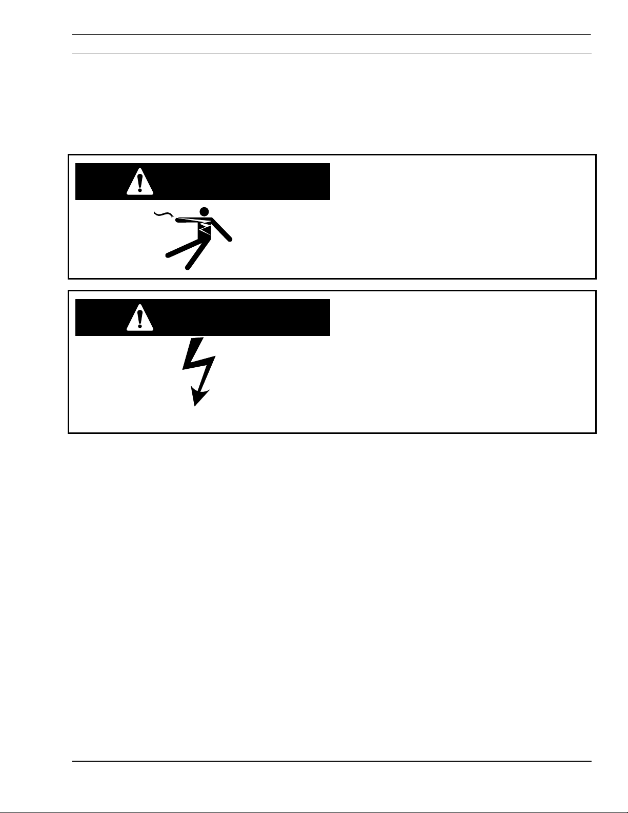
Electric shock hazard.
WARNING
Improper grounding can cause severe injury
or death.
Machine must be properly grounded before
put into service.
Improper Grounding Can Damage
WARNING
Machine And Electrical
Components.
• Machine must be properly grounded
before put into service.
• Cutting table must be properly grounded
to
a good Earth ground rod.
SmartFlow 2.5
1-5
SECTION 1 SAFETY
1.6 Operating a Plasma Cutting Machine
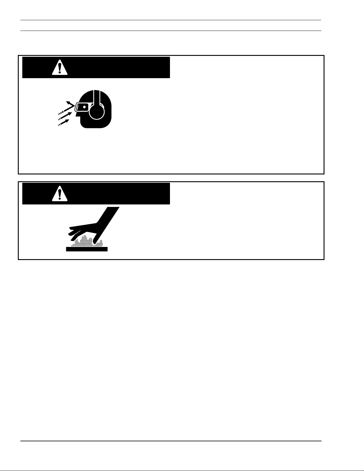
WARNING
hazards.
• Hot spatter can burn and injure eyes.
Wear goggles to protect eyes from burns
and flying debris generated during
operation.
• Chipped slag may be hot and fly far.
Bystanders should also wear goggles and
safety glasses.
• Noise from plasma arc can damage
hearing. Wear correct ear protection when
cutting above water.
Burn hazard.
WARNING
Hot metal can burn.
• Do not touch metal plate or parts
immediately after cutting. Allow metal time
to cool, or douse with water.
Flying debris and loud noise
• Do not touch plasma torch immediately
after cutting. Allow torch time to cool.
1-6
SmartFlow 2.5
SECTION 1 SAFETY
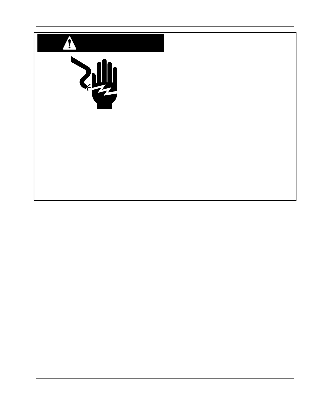
WARNING
Hazardous voltages. Electric shock
can kill.
• Do NOT touch plasma torch, cutting table
or cable connections during plasma
cutting process.
• Always turn power off to plasma power
supplies before touching or servicing
plasma torch.
• Always turn power off to plasma power
supplies before servicing any system
component.
• Do not touch live electrical parts.
• Keep all panels and covers in place when
machine is connected to power source.
• Wear insulating gloves, shoes, and
clothing to insulate yourself from the
workpiece and electrical ground.
• Keep gloves, shoes, clothing, work area,
and equipment dry.
• Replace worn or damaged cables.
SmartFlow 2.5
1-7

SECTION 1 SAFETY
Fume hazard.
WARNING
Fumes and gases generated by the plasma
cutting process can be hazardous to your
health.
• Do NOT breathe fumes.
• Do not operate plasma torch without fume
removal system operating properly.
• Use additional ventilation to remove
fumes if necessary.
• Use approved respirator if ventilation is
not adequate.
• Provide positive mechanical ventilation
when cutting galvanized steel, stainless
steel, copper, zinc, beryllium, or cadmium.
Do not breathe these fumes.
• Do not operate near degreasing and
spraying operations. Heat or arc rays can
react with chlorinated hydrocarbon vapors
to form phosgene, a highly toxic gas and
other irritant gases.
1-8
SmartFlow 2.5

SECTION 1 SAFETY
Radiation hazard.
WARNING
Arc rays can injure eyes and burn skin.
• Wear correct eye and body protection.
• Wear dark safety glasses or goggles with
side shields. Refer to following chart for
recommended lens shades for plasma
cutting:
Arc Current Lens Shade
Up to 100 Amps Shade No. 8
100-200 Amps Shade No. 10
200-400 Amps Shade No. 12
Over 400 Amps Shade No. 14
• Replace glasses/goggles when lenses are
pitted or broken
• Warn others in area not to look directly at
the arc unless wearing appropriate safety
glasses.
• Prepare cutting area to reduce reflection
and transmission of ultraviolet light.
Paint walls and other surfaces with
dark colors to reduce reflections.
Install protective screens or curtains
to reduce ultraviolet transmission.
SmartFlow 2.5
1-9

SECTION 1 SAFETY
Ruptured Gas Cylinders Can Kill
WARNING
Mishandling gas cylinders can rupture and
violently release gas.
• Avoid rough handling of cylinders.
• Keep cylinder valves closed when not in
use.
• Maintain hoses and fittings in good
condition.
• Always secure cylinders in an upright
position by chain or strap to a suitable
stable object not part of an electrical
circuit.
• Locate cylinders away from heat, sparks
and flames. Never strike an arc on a
cylinder.
• Use approved pressure reducing regulator
for the specific gas.
• Refer to CGA Standard P-1, “Precautions
for Safe Handling of Compressed Gases in
Cylinders”, available from Compressed
Gas Association.
Explosion hazard.
WARNING
• Certain molten aluminum-lithium (Al-Li)
alloys can cause explosions when plasma
cut OVER water.
These alloys should only be dry cut
on a dry table.
DO NOT dry cut over water.
Contact your aluminum supplier for
additional safety information
regarding hazards associated with
these alloys
• Do not cut in atmospheres containing
explosive dust or vapors.
• Do not carry any combustibles on your
person (e.g. butane lighter)
.
1-10
• Do not cut containers that have held
combustibles.
SmartFlow 2.5
SECTION 1 SAFETY
WARNING
Burn Hazard.
Heat, spatter, and sparks cause fire and
burns.
• Do not cut near combustible material.
• Do not have on your person any
combustibles (e.g. butane lighter).
• Pilot arc can cause burns. Keep torch
nozzle away from yourself and others
when activating plasma process.
• Wear correct eye and body protection.
• Wear gauntlet gloves, safety shoes and
hat.
• Wear flame-retardant clothing covering all
exposed areas.
• Wear cuff-less trousers to prevent entry of
sparks and slag.
• Have fire extinguishing equipment
available for use.
SmartFlow 2.5
1-11

SECTION 1 SAFETY
1.7 Service Precautions
WARNING
Hazardous voltages. Electric shock
can kill.
• Do NOT touch plasma torch, cutting table
or cable connections during plasma
cutting process.
• Always turn power off to plasma power
supplies before touching or servicing
plasma torch.
• Always turn power off to plasma power
supplies before removing covers or
panels to service any system component.
• Do not touch live electrical parts.
• Keep all panels and covers in place when
machine is connected to power source.
• Keep gloves, shoes, clothing, work area,
and equipment dry.
• Inspect power and ground leads cables for
wear or cracking. Replace worn or
damaged cables. Do not use if damaged.
• Never bypass safety interlocks.
• Follow lock-out procedures.
Establish and adhere to preventive
CAUTION
maintenance. A composite program can be
established from recommended schedules.
Avoid leaving test equipment or hand tools on
machine. Severe electrical or mechanical
damage could occur to equipment or
machine.
1-12
SmartFlow 2.5

SECTION 1 SAFETY
Extreme caution should be used when
CAUTION
probing circuitry with an oscilloscope or
voltmeter. Integrated circuits are susceptible
to over voltage damage. Power off before
using test probes to prevent accidental
shorting of components.
All circuit boards securely seated in sockets,
all cables properly connected, all cabinets
closed and locked, all guards and covers
replaced before power is turned on.
1.8 Safety References
The following nationally recognized publications on
safety in welding and cutting operations are
recommended. These publications have been
prepared to protect persons from injury or illness and
to protect property from damage, which could result
from unsafe practices. Although some of these
publications are not related specifically to this type of
industrial cutting apparatus, the principles of safety
apply equally.
SmartFlow 2.5
1-13

SECTION 1 SAFETY
1.8.1 USA Domestic
• “Precautions and Safe Practices in Welding and
Cutting with Oxygen-Fuel Gas Equipment,” Form
2035. ESAB Cutting Systems.
• “Precautions and Safe Practices for Electric
Welding and Cutting,” Form 52-529. ESAB Cutting
Systems.
• “Safety in Welding and Cutting” - ANSI Z 49.1,
American Welding Society, 2501 NW 7th Street,
Miami, Florida, 33125.
• “Recommended Safe Practices for Shielded
Gases for Welding and Plasma Arc Cutting” - AWS
C5.10-94, American Welding Society.
• “Recommended Practices for Plasma Arc
Welding” - AWS C5.1, American Welding Society.
• “Recommended Practices for Arc Cutting” -
AWS C5.2, American Welding Society.
• “Safe Practices” - AWS SP, American Welding
Society.
• “Standard for Fire Protection in Use of Cutting
and Welding Procedures” - NFPA 51B, National
Fire Protection Association, 60 Batterymarch
Street, Boston, Massachusetts, 02110.
• “Standard for Installation and Operation of
Oxygen - Fuel Gas Systems for Welding and
Cutting” - NFPA 51, National Fire Protection
Association.
• “Safety Precautions for Oxygen, Nitrogen,
Argon, Helium, Carbon Dioxide, Hydrogen, and
Acetylene,” Form 3499. ESAB Cutting Systems.
Obtainable through your ESAB representative or
local distributor.
• "Design and Installation of Oxygen Piping
Systems," Form 5110. ESAB Cutting Systems.
• “Precautions for Safe Handling of Compressed
Gases in Cylinders”, CGA Standard P-1,
Compressed Gas Association.
• Literature applicable to safe practices in welding
and cutting with gaseous materials is also available
from the Compressed Gas Association, Inc., 500
Fifth Ave., New York, NY 10036.
1-14
SmartFlow 2.5

SECTION 1 SAFETY
1.8.2 International
Accident Prevention
VBG 1 General Provisions
VDE Regulations
TRAC Technical Rules for Acetylene and Carbide Stores
VBG 4 Electrical Equipment and operating
Equipment
VBG 15 Welding, Cutting and related working
methods
VBG 48 Shot Blasting Works
VBG 61 Gases
VBG 62 Oxygen
VBG 87 Operating liquid jet cutting machines
VBG 93 Laser beams, accident prevention and
Electro-technology
VBG 121 Noise
VDE 0100 Erection of power installations with normal
voltages up to 1000 volts
VDE0113 Electrical equipment of industrial machines
VDE 0837 Radiation safety of laser products; users
guide (DIN EN 60825)
VDE 0837-
50
TRAC-204 Acetylene lines
Specification for laser guards
TRAC-206 Acetylene cylinder battery systems
TRAC-207 Safety devices
TRG Technical Rules for Pressure gases
TRG 100 General regulations for pressure gases
TRG 101 Pressure gases
TRG 102 Technical gas mixtures
TRG 104 Pressure gases; alterative use of
compressed gas tanks
SmartFlow 2.5
1-15

SECTION 1 SAFETY
DIN Standards
DIN EN ISO Harmonized Standards
DIN 2310
Part 1
DIN 2310
Part 2
DIN 2310
Part 4
DIN 2310
Part 5
DIN 4844
Part 1
DIN EN
292/1 and 2
DIN EN 559 Hoses for welding, cutting and allied
DIN EN 560 Hose connections and hose couplings for
DIN EN 561 Gas welding equipment hose couplings
Thermal cutting; terminology and
nomenclature
Thermal cutting; determination of quality of cut
faces
Thermal cutting; arc plasma cutting; process
principles, quality, dimensional tolerances
Thermal cutting; laser beam cutting of metallic
materials; process principles
Safety markings (DIN EN 7287)
Safety of machinery
processes
equipment for welding, cutting and allied
processes
DIN EN
626-1
DIN EN
848-1
DIN EN
1829
DIN EN
9013
DIN EN
12584
DIN EN
12626
DIN EN
28206
DIN EN
31252
DIN EN
31553
DIN EN
60204-1
DIN EN
60825
DIN EN 999 Arrangement of protection devices
Safety of machines, reduction of risks to
health
Single spindle vertical milling machines
High pressure water jet machines
Thermal cutting, oxygen cutting, process
principles, dimensional tolerances
Imperfections in oxy/fuel flame cuts, laser
beam cuts and plasma
Laser processing machines
Acceptance testing for oxygen cutting
machines
Laser Equipment
Laser and laser related equipment
Electrical equipment of machines
Radiation safety of laser products
VDI Guidelines
1-16
VDI 2906 Quality of cut faces on metallic workpieces;
VDI 2084 Room air; Technical systems for welding
SmartFlow 2.5
abrasive water jet cutting and arc plasma
cutting
workshops

SECTION 2 DESCRIPTION
2.1 Introduction
The SmartFlow 2.5 Cutting System is a
streamlined, high performance-cutting package
designed for use exclusively with the ESAB Vision
CNC. This advanced technology integrates gas
and water control into the machine CNC.
Using a system of proportional valves driven by
CNC outputs, this system:
• dramatically reduces the amount of plumbing
hardware necessary to control the plasma
torch
• reduced purge time/increased part throughput
• simplified operation with gas and water flow
rates manually controlled at the Vision CNC
process parameter screen
• allows for programmed/automated control of
gas and water flow rates using SDP Files
(SchneidDatenPaket = Cutting Data Package,
see Vision control and programming manuals
for details on SDP Files. Data used to
generate SDP files can be found in your model
specific torch manual.)
• can be used with either a PT-15XL water
injection torch or a PT-600/PT-19XLS dry
cutting torch with secondary shield gas. (The
PT-600 and the PT-19XLS are both dry cutting
torches of similar design.)
2.2 SmartFlow 2.5 and PT-15XL
When the PT-15XL water injection torch is used,
the complete cutting system also requires the
following components:
• PT-15XL plasma torch
• a plasma power supply
• a recirculating water cooler
• coolant pump
• cut water pump
• air curtain regulator
• Vision CNC.
SmartFlow 2.5
2-1

SECTION 2 DESCRIPTION
2.3 SmartFlow
2.5
and PT-19XLS/PT-600
When a dry torch (no water injection) is used, the
SmartFlow 2.5 water injection components are
used to control the secondary shield pressure.
The components of The SmartFlow II Cutting
System with dry torch requires the following
components:
• Vision CNC,
• PT-19XLS or PT-600 plasma torch,
• power supply,
• a recirculating water cooler,
• and coolant pump.
2.4 SmartFlow
2.5
Options
SmartFlow 2.5 with H-35 capability
(H-35 is industry accepted nomenclature
for a gas mixture of 65% argon and 35%
2.5 Gas Requirements
Nitrogen
Oxygen
Compressed Air
SmartFlow 2.5 without H-35 capability
(DISCONTINUED)
hydrogen)
P/N 0560935258 P/N 0560935257
• 125 PSI (8,63 bar) with 0.5”
NPT
• 99.999% purity
• Filtered to 25 microns
• 125 PSI (8,63 bar) with 0.5”
NPT
• 99.999% purity
• Filtered to 25 microns
• 100 PSI (6,9 bar) with 0.5” NPT
• Clean, dry and filtered to 25
microns
2-2
• 150 PSI (10,4 bar)
H-35 (argon/hydrogen)
• Filtered to 25 microns
SmartFlow 2.5

SECTION 2 DESCRIPTION
2.6 Water Supply Requirements
Cooling Water
Deionized Water
(PT-15XL only)
2.7 Electrical Input Requirements
Voltage Supply
Voltage Signals
• 120 PSI (8,28 bar)
• 1.5 gallons per minute (5.68 liters/minute)
• 35 PSI (2,42 bar)
• >200,000 ohms (resistance)
• .5 gallons/minute (1,89 liters/minute) for up to
600A cutting
• 1.5 gallons/minute (5,68 liters/minute) for
600A to 1000A cutting
• +24 VDC for proportional valves, flow and
pressure switches
• +15 VDC for pressure switch
• 120 VAC input to start gas solenoid valve
• 120 VAC input to cut gas solenoid valve
• 120 VAC input to arc starter
• 0-10 VDC input to proportional valves
SmartFlow 2.5
2-3
SECTION 2 DESCRIPTION
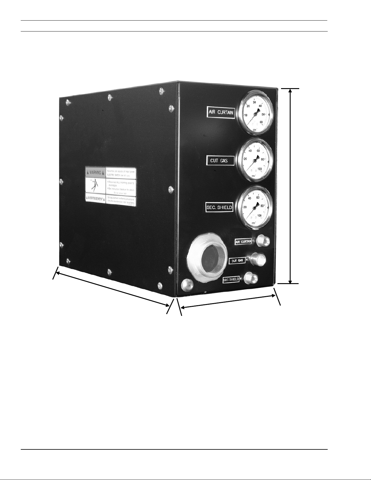
2.8 Dimensions
12.12"
(308mm)
15.62" (396.8mm)
7.5 " (190,5mm)
2-4
SmartFlow 2.5
SECTION 3 INSTALLATION
Electricity Can Kill!
WARNING
Before performing any maintenance or
assembly of this equipment, ensure the
power source (ESP) is turned off and
disconnected.
3.1 Introduction
The SmartFlow 2.5 is a plumbing box that
interfaces with the ESAB Vision machine controls
and the ESP product line of plasma power
sources. An interface pc board receives voltage
signals from the machine CNC that control
proportional and solenoid valves. The result is
CNC management of gas and cutwater or shield
gas delivery to the plasma torch. Analog signal
feedback is sent back to the CNC, creating a
control loop.
The SmartFlow 2.5 can be used with the PT-15
water injection plasma torch or both the dry cutting
PT-19XLS and PT-600 plasma torches with
secondary shield gas.
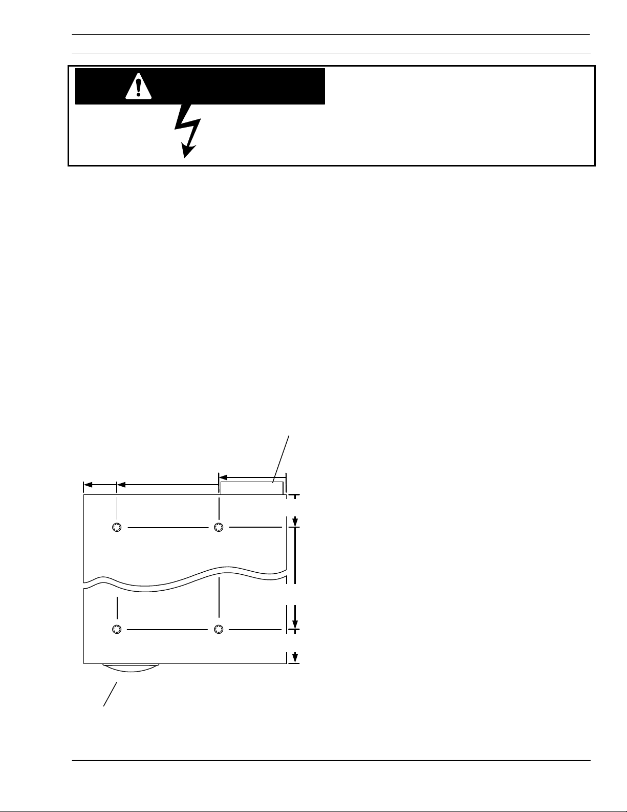
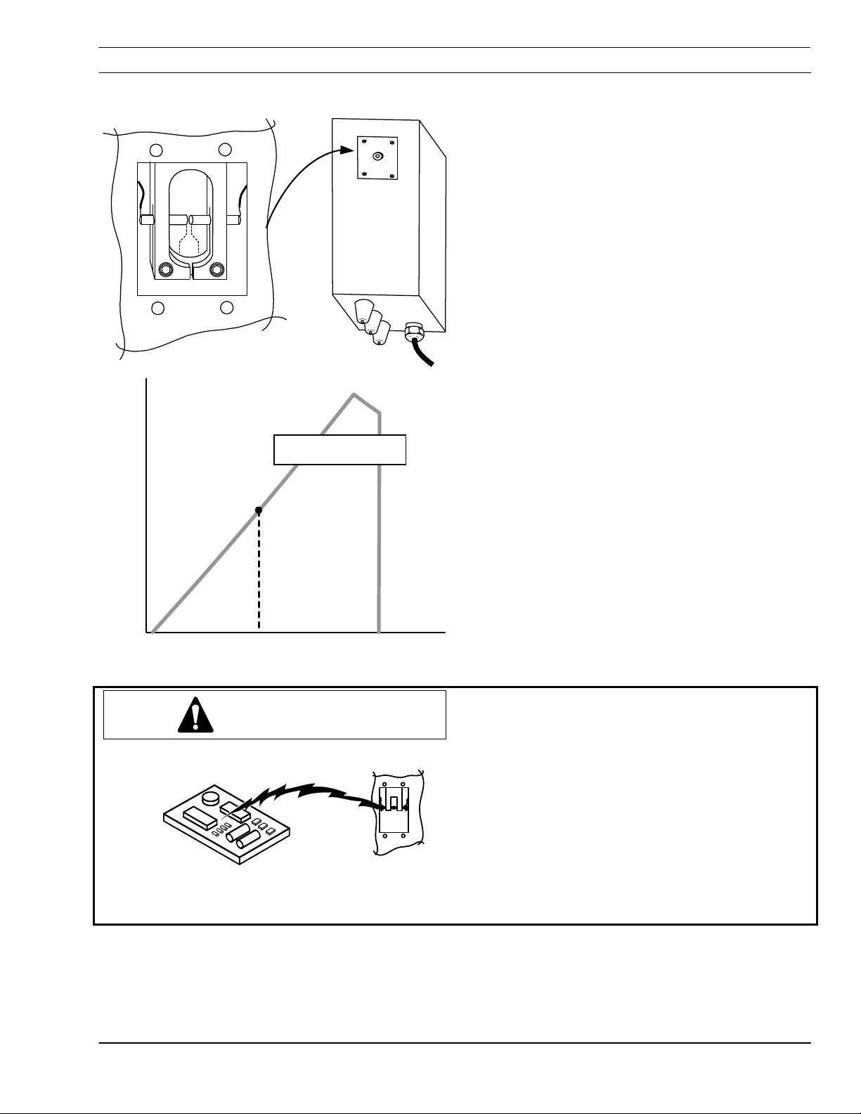
3.2 Box Mounting (Bottom View)
7.25"
184.2 mm
6.515"
165.5 mm
Cable Clamp
2.015"
51.2 mm
0
(Ref)
Gauges (Ref)
0
2.125"
54 mm
If mounting the box is required:
The box has four 6 mm threaded mounting holes
in a pattern offset from longitudinal center. Note
13.125"
333.4 mm
15.125"
384.2 mm
relationship of hole pattern to gauges and cable
clamp.
SmartFlow 2.5
3-1

SECTION 3 INSTALLATION
3.3 Hose and Cable Connections
Control Cable
Clamp/Strain
Relief
1. Remove left side panel of the SmartFlow 2.5
box. Rotate ¼ turn fasteners
counterclockwise.
Left Side Panel
Removed
2. Disassemble the strain relief/clamp block.
(When apart, this strain relief will allow
placement of cables and hoses without
removing plugs and fittings.)
A. Remove six screws holding block to back of
the SM box.
B. Remove four side clamping screws.
3-2
SmartFlow 2.5

SECTION 3 INSTALLATION
Control Cables
3. Place cables in block.
4. Replace four side clamp screws. Do not
tighten.
Power Source Leads
(4/0 Cable)
Pilot Arc Cable
5. Reattach block using three mount screws
along a vertical line.
6. Adjust cable length and tighten the four side
clamp screws.
7. Finish attaching the block to the box with the
other three mount screws.
8. Tighten all screws.
SmartFlow 2.5
3-3

SECTION 3 INSTALLATION
3.3.1 Starter Box Connections
Connection Point
TB4/Buss
TB1 – Pilot arc ground cable from the plasma
power source (ESP).
TB4 – Connected to buss bar (brass block just
below starter box) inside the SmartFlow box.
TB2 – Pilot Arc Torch cable from the torch leads.
3-4
SmartFlow 2.5
SECTION 3 INSTALLATION
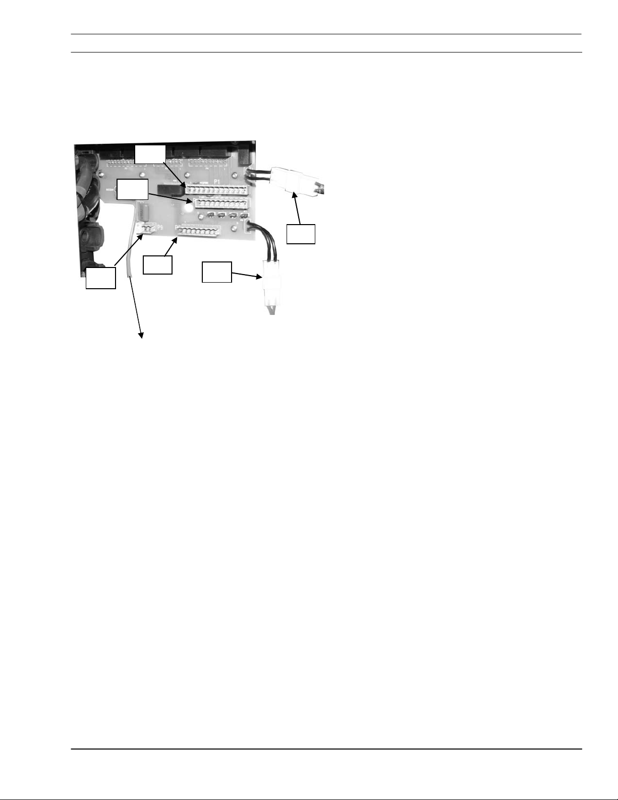
3.3.2 PC Board Connections
P1
P3
P1 – 12 pin connector, CNC control lead (valves)
P2 – 8 pin connector, CNC control lead (cutwater/
secondary shield)
P3 – 10 pin connector, CNC control lead (cut gas)
P6 – Cooling water flow switch
P8 – High frequency arc start AC power
P9 – Voltage divider
P9
To arc start buss
P2
P6
P8
Reverse side (not shown)
P4 – 10 pin connector, valve control lead (valves)
P5 – 8 pin connector, manifold control lead
(cutwater/ secondary shield)
P7 – 12 pin connector, manifold control lead (cut
gas)
Note:
For more detailed information, refer to PC
board schematic in Section 6.
SmartFlow 2.5
3-5
SECTION 3 INSTALLATION
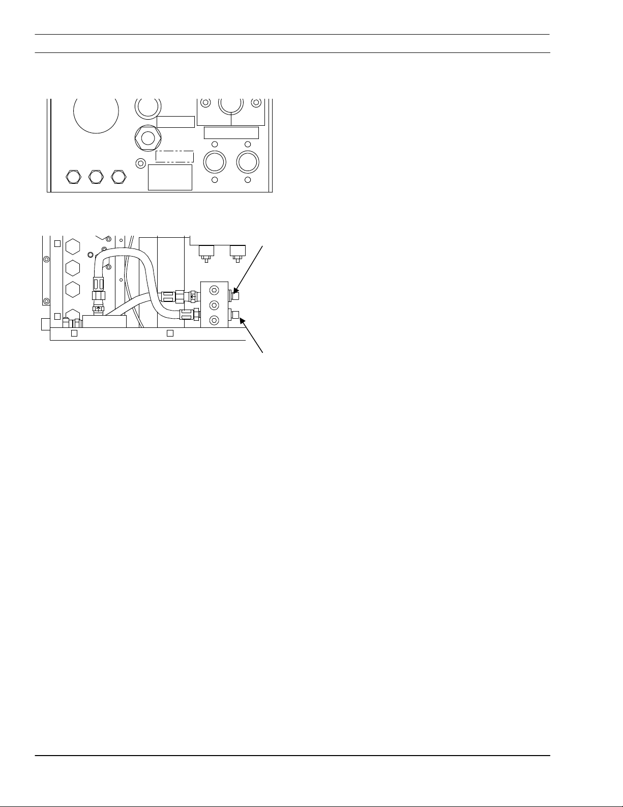
3.3.3 Torch Cooling Water Connections
Coolant Connections To and From Power
Source
AIR
COOLING WATER
OUT
IN
When packaged with a torch and power supply at
the factory, connections are labeled. Additional
CUT WATER
SERIAL
NUMBER
labels are available if re-labeling becomes
necessary. Tracing Smart Flow 2.5 interior lines
can identify the proper connections. Flow switch is
located on the “IN” line.
Coolant OUT (from
torch)
Coolant Connections To And From Torch
Note arrows on fittings indicating coolant flow
OUT
IN
Left Side Panel
Removed
Coolant IN (to torch)
direction.
Coolant Out has right-hand threads.
Coolant In has left-hand threads
3-6
SmartFlow 2.5
SECTION 3 INSTALLATION
3.3.4 Power Source To SMF 2.5 Buss Connection
4/0 power source cables
1. Strip 4/0 insulation, approximately 38 mm.
2. Insert 4/0 cable in buss hole until copper
extends to the edge of the buss block.
Buss
3. Tighten locking screw(s) on cable.
Note:
The buss will accommodate three cables.
(1) 4/0 – 400 amps
(2) 4/0 – 750 amps
(3) 4/0 – 1000 amps
Careful attention while stripping insulation
NOTICE
will make installation of the 4/0 cable in the
buss easier. Do not spread or flare the
copper conductors.
SmartFlow 2.5
3-7

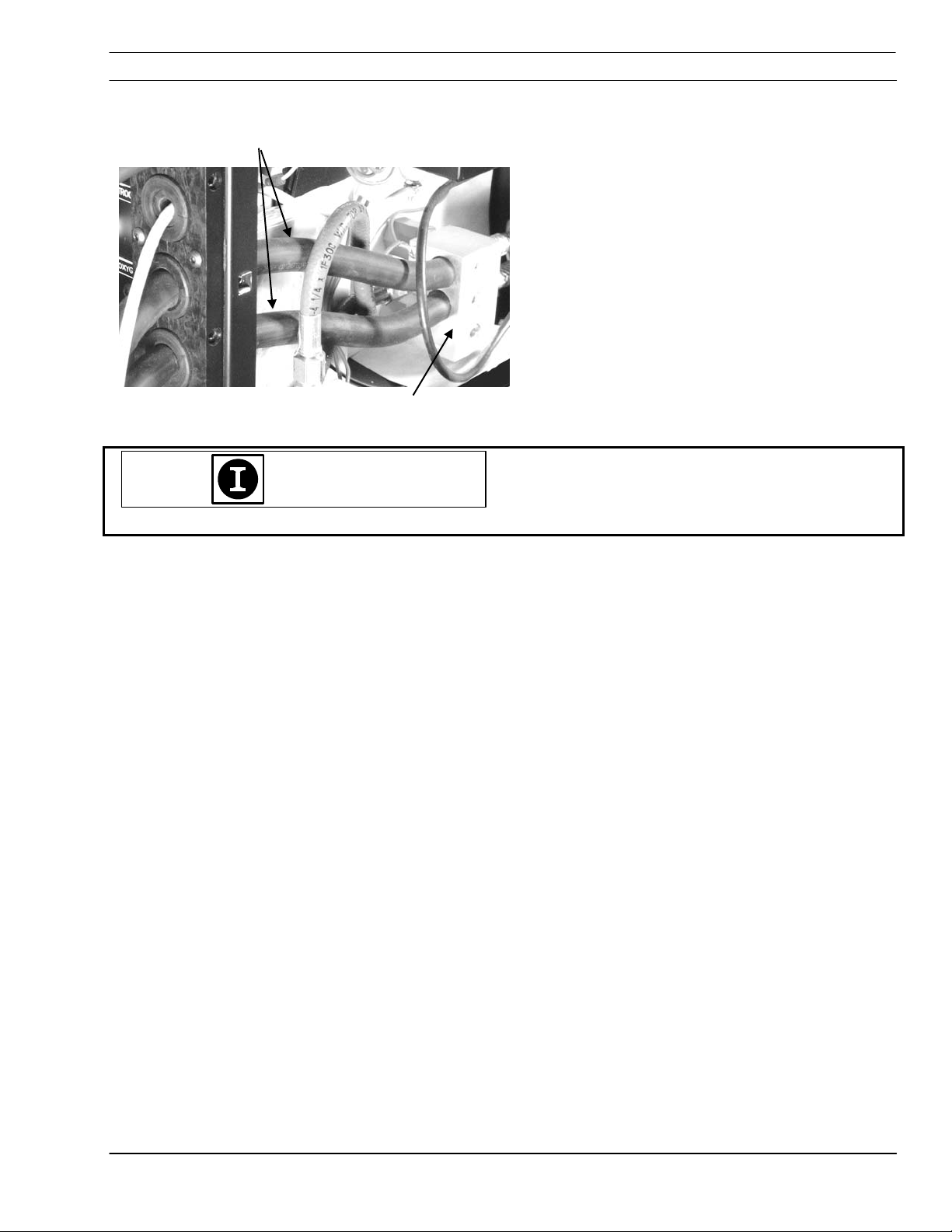
SECTION 3 INSTALLATION
3.4 Nomex Insulation
Arc Start Box
Nomex
Insulation
High Frequency Cable from ESP
Plasma Power Source
Buss
3.5 Gas Connections
3.5.1 Gas Lines From Supply.
Position Nomex insulation to prevent any possible
arcing between the buss and arc start box
terminals.
Replace side panels of SmartFlow 2.5 enclosure.
Gas Connections are made on the exterior of the
SM box. Gas lines are connected to the back
from supply sources and the front for the torch.
Unfiltered Gas Will Clog Proportional
CAUTION
Valves
Dirt particles will clog small orifices in proportional
valves.
3-8
All gas supplies must have a 25 micron filter
installed between supply and gas regulator panel.
EASB Filter P/N 56998133 (replacement filter
element P/N 0560988406)
When using the PT-19XLS or PT-600 torch with a
secondary shield, air supply must be filtered and
dry using a minimum 25 micron filter.
Proportional valves contain no serviceable parts.
Replace valve assembly with factory parts.
SmartFlow 2.5

SECTION 3 INSTALLATION
Gas Line Contamination Will Damage
CAUTION
1
2
NITROGEN
Proportional Valves
Purge Gas Lines
Before connecting gas delivery lines to the
SmartFlow 2.5V, purge all lines thoroughly.
Residue from the hose manufacturing process
may clog/damage the proportional valves in
your SmartFlow 2.5.
1. Purge gas and air lines completely before
connecting to 25 micron gas filters.
3
H-35
AIR
4
5
OXYGEN
AIR
SECONDARY
SHIELD
SERIAL
NUMBER
COOLING WATER
OUT
IN
Back of SM 2.5 Plumbing Box
1 Nitrogen (N2)
2 Alternate Cut Gas Air or H-35. Units differ on
thread type. Standard version (air) have right hand
threads. The H-35 version has left hand threads.
3
Oxygen (O
4 Torch Air
5 Secondary Shield or Cutwater (depends on torch)
)
2
2. Connect oxygen, H-35, nitrogen and airlines to
gas filters.
3. Purge gas/air lines between regulator panel
and SmartFlow 2.5 plumbing box.
4. Connect gas/air lines to back of plumbing box.
SmartFlow 2.5
3-9

SECTION 3 INSTALLATION
3.5.2 Gas Pressure Setup
Adjust pressure at the regulator panel while gas is
flowing.
3.6 Cut Water Setup (PT-15XL)
See system requirements for description of
cutwater.
Gas Type Pressure
Oxygen 125 PSI (8,63 Bar)
Nitrogen 125 PSI (8,63 Bar)
H-35 150 PSI (10,4 Bar)
A supply of deionized water is required for the
installation of cutwater when using the PT-15XL.
A minimum regulated pressure of 30 psi (2,07 bar)
supply is required to prevent cavitation in the
cutwater pump.
Pressure from the cutwater pump to the
SmartFlow should be adjusted to 120 psi (8,28
bar). Refer to the cutwater pump manual for this
procedure.
3-10
SmartFlow 2.5

SECTION 3 INSTALLATION
3.7 Secondary Shield Gas Setup (PT-19XLS/PT-600)
Secondary shield gas (air or N2) must be dry and
filtered to a minimum of 25 microns and regulated
to 60 PSI (4,14 bar). Excess moisture in shield
gas may cause arcing inside the torch and/or poor
consumable life. This gas supply (pre-filtered)
uses the same fitting as the cutwater hose in back
of the plumbing box.
Secondary shield gas regulator
Air regulator
SmartFlow 2.5
3-11
SECTION 3 INSTALLATION
3.8 A Component Relationship Block Diagram
1
5
4
2
4
0
0
C
3
6
7
N2
O2
Air
H-35
8
17
9
10
18
3-12
11
12
13
14
15
16
SmartFlow 2.5

SECTION 3 INSTALLATION
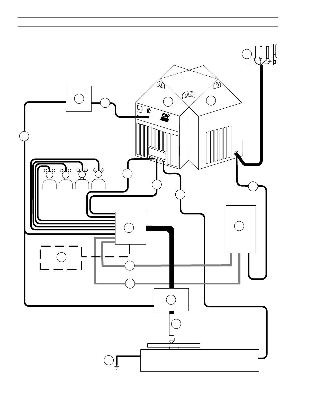
System Interconnecting Block Diagram with Smart Flow 2.5
1
3 phase with ground (wall disconnect)
2
Front view of plasma power source
3
Rear view of plasma power source
4
Remote to CNC
5
CNC
6
CNC Input/Output to Smart Flow 2.5
7
Torch Lead (-)
8
Pilot Arc Lead
9
Work Lead (+)
10
11
12
13
14
15
16
17
18
SmartFlow 2.5
Cut Water Pump (required for PT-15)
Cooling Water to Torch
Cooling Water from Torch
Voltage Height Control
Plasma Torch Lead Bundle and Torch
Earth Ground
On/Off Control
WC-7C Water Cooling
SmartFlow 2.5
3-13

SECTION 3 INSTALLATION
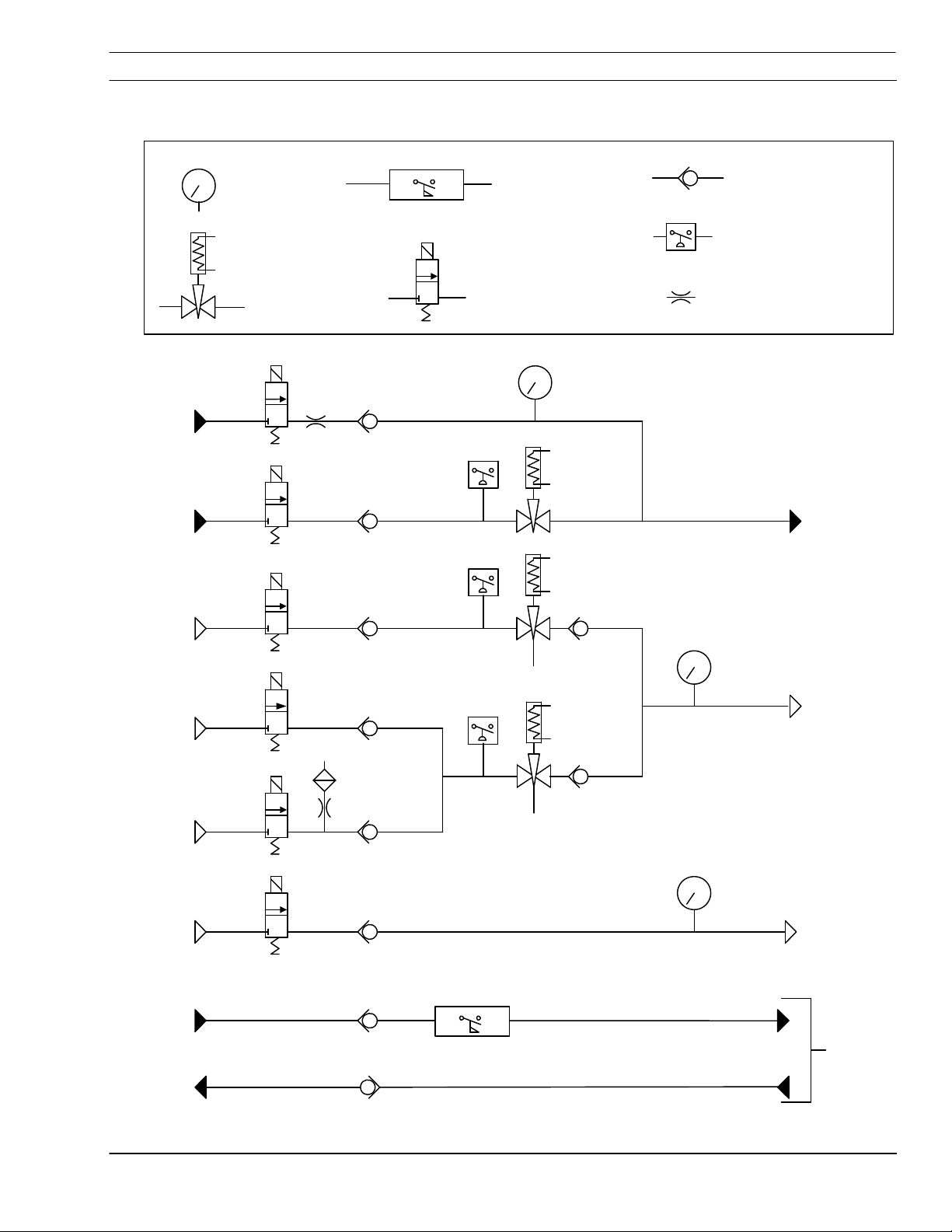
3.9 Fluid Schematic – SmartFlow 2.5 Standard and H-35 Versions – See note
Gauge
Proportional
Valve
Auxilery
Cut Water
Valve 3
Secondary
Shield/
Cut Water
IN
Vent
Oxygen
IN
Vent
Air/H-35
IN
See note.
Nitrogen
IN
Valve 2
N
2
Orifice
Vent
Air IN
Flow Switch
Cooling
Water IN
Cooling
Water OUT
3-14
Flow Switch
2 way Solenoid
Valve
0-100 PSI (6,9 bar)
PS2
PS
PS3
Valve 1
PS
See note.
PS1
PS
Purge
IN OUT
SmartFlow 2.5
Check Valve
PS
Pressure Switch
Flow Restriction Orifice
Secondary
Shield/
Cut Water
OUT
0-100 PSI (6,9 bar)
Plasma
Gas
H-35 Version valve 2 is rated
Note:
for fuel gas. Inlet has left-hand
threads and a louvered cover.
The Standard Version valve 2 is rated for
non-fuel gas, Unit has a right-hand
threaded inlet and no louvers on the cover.
0-50 PSI (3,45 bar)
Air Curtain
To torch

SECTION 4 OPERATION
4.1 Operation Introduction
A major advantage of the SmartFlow 2.5 is that
NOTICE
4.2 Pressure Gauges
operating parameters are managed by the
machine CNC. There are no operating procedures
necessary with the SmartFlow 2.5. Management
is accomplished either with manual inputs on the
Vision cutting parameter screen or using the
ESAB system of Process Parameter Files.
Note:
Process Parameter Files (know by the acronym …
SDP for SchneidDatkenPaket) are files stored in
the Vision Control memory containing all
necessary information for cutting a thickness and
a material type. It is specific to material, thickness,
torch model, gas and material type. The
information used to create SDP files can be found
in your torch manual under Cutting Data,
Operation, Section 4. Refer to Vision CNC Part
Programming manual for more detail on the
creation and use of SDP files.
See your specific torch manual for cutting
parameter settings for using the
SmartFlow 2.5 Plumbing Box. These
settings can be found in the form of
cutting data charts located in the operation
section of the torch manual.
Pressure gauges display actual pressure to the
torch. They provide visual feedback to the
operator, and can be helpful in spotting torch
problems.
4.3 Pressure Switches.
Pressure switches monitor line pressure and
Smart Flow 2.5
provide inputs to the CNC. If the pressure drops
below a preset level, the CNC can shut the
process down. Switches are in-line between the
solenoid and the proportional valve for cut water
(or secondary shield), H-35, and oxygen/nitrogen
lines.
4-1

SECTION 4 OPERATION
This page intentionally left blank.
4-2
Smart Flow 2.5

SECTION 5 Maintenance
5.1 SmartFlow 2.5 Maintenance Introduction
This section provides adjustment or replacement
procedures for those serviceable parts inside the
SmartFlow 2.5 plumbing box.
Only trained personnel should perform
maintenance on this equipment.
Electric Shock Can Kill!
WARNING
CAUTION
Always disconnect power from the ESP
power source and the cutting machine
before opening or servicing the SmartFlow
2.5 plumbing box.
Only Qualified Maintenance Personnel
Should Repair And Maintain This
Equipment.
Smart Flow 2.5
5-1
SECTION 5 Maintenance
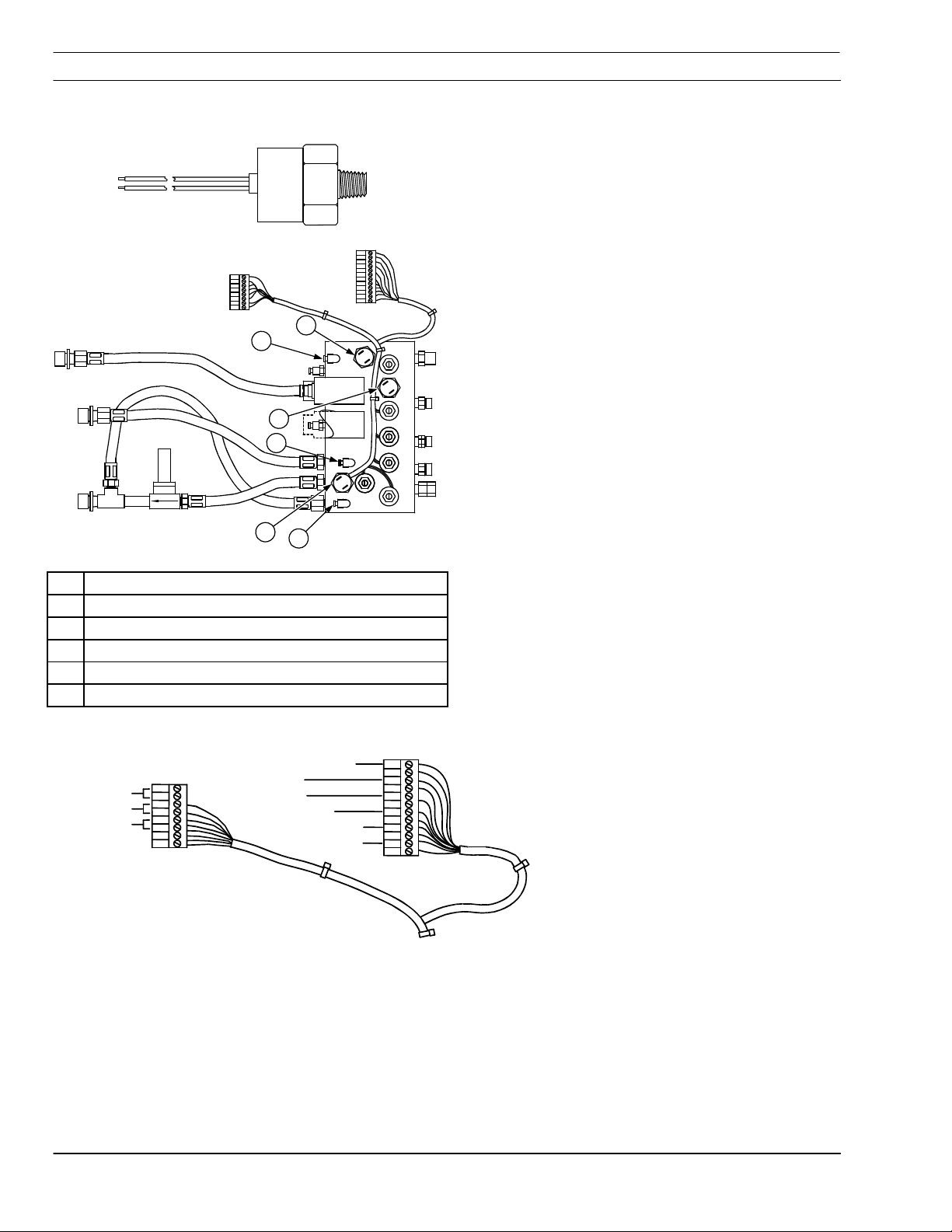
5.2 Pressure Switches
P5
1
2
3
4
5
6
P7
Gas Pressure Switch monitors the pressure of
plasma gas supply to the plumbing box. One
switch monitors O
monitoring the alternate gas: Air or H-35 / N
. The other switch is used for
2
.
2
Note:
H-35 is an industry name for a mixture of 65 %
argon and 35% hydrogen.
Cut Water/Secondary Shield Switch monitors
the pressure of either cutwater or secondary
shield gas, depending on the torch application.
These switches are wired as an input to the CNC.
Logic codes in the control look for a change of
state (low/high) of the input signals, therefore
these switches cannot be jumpered out of the
circuit.
Both pressure switches are factory set and nonadjustable to close at 50 PSI (3.45 Bar). They
contain no serviceable parts. Replacement P/N
952920.
1 Oxygen Pressure Switch
2 Plasma Gas Pressure Gauge Tap
3 Air or H-35 / N2 Plasma Gas Pressure Switch
4 Air Curtain Pressure Gauge Tap
5 Cut Water/Secondary Shield Pressure Switch
6 Cut Water Pressure Gauge Tap
P5 and P7 Wiring
N2
AIR
O2
N2
AIR 1
P7
12
11
10
9
8
7
6
5
4
3
2
CUT WATER
O2
Air or H-35/N2
O2
8
7
6
5
4
3
2
1
CUT H2O AUX
CUT H2O
Air or H-35
CUT H2O AUX
CUT H2O
Air or H-35
P5
5-2
Smart Flow 2.5
SECTION 5 Maintenance
5.3 Spark Gap Of the Arc Starter
The SmartFlow 2.5 uses a high frequency arc
starter to initiate the plasma arc within the cutting
torch.
The arc starter box is mounted in the upper right
corner of the plumbing box. The arc starter box
contains an adjustable spark gap.
The recommended spark gap setting is
0.040" (1,0 mm).
HIGH
Decreased Spark Gap from 0.040” (1 mm):
Starting
decreased
• Positive Effect – smaller risk of high frequency
• Negative Effect- starting reliability is
interference
Increased Spark Gap from 0.040” (1 mm):
• Negative Effect – increased damage risk from
Risk of High Frequency
Interference Damage
LOW
0
.040"
(1 mm)
Spark Gap
high frequency interference
• Positive Effect - starting reliability increased (to
a point where it doesn’t work at all).
High Frequency Interference Can Damage
CAUTION
Machine Electronic Components
Potentially damaging high frequency interference
may result from increasing the spark gap beyond
recommendation. This electrical interference may
find its’ way to pc boards in the electronics cabinet
or Vision control. The result will be failure of some
portion of machine function.
Do not set spark gap beyond
recommended distance of 0.040” (1,0 mm)
Smart Flow 2.5
5-3

SECTION 5 Maintenance
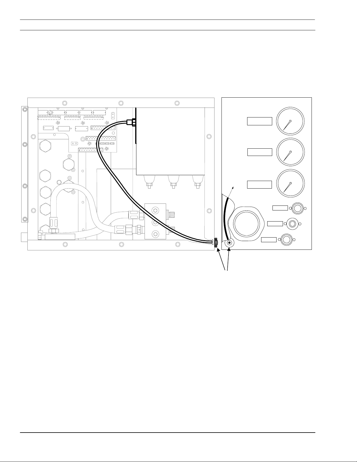
5.3.1 Arc Starter Box Troubleshooting
Arc Starter Box schematic
If it is determined that the arc starter box has
failed, contact ESAB for replacement box.
To remove the arc starter box, locate the eight (8)
mounting screws on the interior mounting wall.
The air curtain and cut gas gauges will need to be
moved to access mounting screws. Loosen clamp
screws on gauges and slide gauges forward to
access arc starter box screws. Remove arc starter
box mounting screws and disconnect wires at
TB1, TB2, TB4 and the black lead 120 vac input.
Make sure to note proper wire connection
locations for reassembly. Reassemble arc starter
box, make wire connections and replace gauges.
5-4
(8) Arc Starter Box mounting screws
Air Curtain gauge
Clamp screws
Cut Gas Gauge
Smart Flow 2.5

SECTION 5 Maintenance
Electric Shock Can Kill!
WARNING
Always turn power off before opening and
servicing the SmartFlow 2.5 plumbing box.
5.4 Spark Adjustment Procedure
1. Disconnect input power to plasma power
source (ESP) and cutting machine.
2. Remove left and right side covers from the
SmartFlow 2.5. Mounting screws for the arc
starter box are accessed from the manifold
side (right side) of the SM II.
1
Spark Gap Access
2
Fiber Optic Cable
3
Spark Gap of 0.040” (1 mm)
3. Disconnect fiber optic cable from arc starter
box.
4. Remove arc starter box. Mounting screws are
accessed from the opposite side of the SM
2.5. Removal of gauge(s) may be necessary to
see some screws.
1
2
3
ARC Starter Box
5. Remove access cover from the arc starter.
6. Use a 0.040” (1 mm) feeler gauge or shim to
measure the spark gap setting.
7. Adjust as required. When correctly adjusted,
there should be slight pressure felt when a
back and forth motion is applied to the shim.
8. Replace access cover and remount arc starter
box.
9. Replace side panels.
Smart Flow 2.5
5-5

SECTION 5 Maintenance
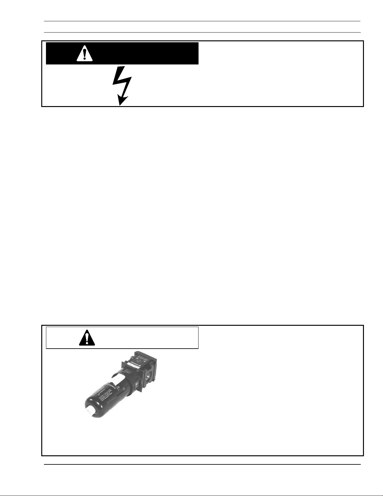
5.5 Gas Proportional Valves
P/N 0558001068
O2 Proportional Valve
Oxygen rated.
Gas proportional valves contain no user
serviceable parts. In case of failure, the valve
must be replaced.
P/N 0558001065
H-35 / N2 Proportional Valve
Fuel gas rated.
Easily distinguishable with nickel-plated valve
body. Gas proportional valves contain no user
serviceable parts. In case of failure, the valve
must be replaced.
5.6 Cutwater/Secondary Shield Proportional Valve
P/N 56997044
This proportional valve contains no user
serviceable parts. The valve must be replaced in
case of failure. This is the only valve that can be
calibrated if necessary. See troubleshooting
section for calibration procedure.
5-6
Smart Flow 2.5

SECTION 5 Maintenance
5.7 Cooling Water Flow Switch
2
P/N 636383
The cooling water circuit uses a 1.0 gallon (3.8
liters) flow switch to monitor cooling water flow. It
measures actual flow through the torch in the
cooling water return line.
The switch is wired as an input to the CNC. The
control looks for a change of state of the input
1
signal when the plasma station is turned on. This
switch cannot be jumpered out of the circuit.
Type of cooling water problems:
• Insufficient flow due to a restriction in the
cooling water circuit.
2
The switch may be disassembled and cleaned
if found to have a restriction.
3
• Sufficient flow but no flow closure.
If measurement of the actual cooling water
4
flow rate indicates more than 1.0 gallon
(3.8 liters) per minute, but the switch does
not close, the switch may be damaged or
clogged. Clean or replace as necessary.
1
1 Retainer Ring
2 Flow Switch
3 Spring
4 Piston
Smart Flow 2.5
5-7

SECTION 5 Maintenance
5.8 Gas Filters
Nitrogen, oxygen, and secondary shield gases
must be filtered before entering the SmartFlow II.
Check these filters regularly (dependent on usage
and cleanliness of supply). Replace filter as
required.
Unfiltered Gas Will Clog Proportional
CAUTION
Valves
Gas filters must be installed in the gas
supply lines in front of the gas regulator
panel. A 25 micron filter is required.
P/N 56998133. Replacement filter element
P/N 0560988406
5-8
Smart Flow 2.5
SECTION 6 TROUBLESHOOTING
Electric Shock Can Kill!
WARNING
Disconnect power before removing side
panels.
6.1 Troubleshooting Introduction
The SmartFlow 2.5 has proven to be a very
reliable product. Regular maintenance is important
for many years of trouble free use.
This section contains a brief description of the
most common problems, schematics, and
technical diagnostic tools.
• Cooling Water Circuit
• Cut Water
• Plasma Gas
• Secondary Shield
• Spark
• Process Diagnostics
The SmartFlow 2.5 is designed to support the PT15XL, PT-19XLS and PT-600 plasma torches.
• The PT-15XL torch uses cutwater.
• PT-19XLS and PT-600 torches introduce a
secondary gas shield. Secondary shield
utilizes the same solenoid and proportional
valve used for the cutwater on the PT15XL.
All gases supplied to the SmartFlow 2.5
CAUTION
must be filtered to 25 microns. Small
orifices in proportional valves will become
clogged if filters are neglected or bypassed.
Do Not Attempt to Clean. Replacement of
manifold assembly may be necessary.
Replacement of proportional valves only is
possible. Thoroughly flush manifold and gas
lines with N
before reassembly.
2
Because proportional valves contain the
smallest gas passages, replacement or
cleaning of check valves is not recommended.
Avoid any potential problems by
appropriately filtering plasma and shield
gases.
SmartFlow 2.5
6-1

SECTION 6 TROUBLESHOOTING
6.2 Cooling Water Circuit
The cooling water circuit consists of two reverse
5
1 Torch
2 To torch check valve
3 Flow Switch
4 Return coolant check valve
5 Water cooler
4
2
3
1
flow check valves and a flow switch. It is a closed
loop re-circulating system which cools the
electrode
and torch body of the PT-15XL torch. The PT19XLS and PT-600 torches have electrode,
nozzle, nozzle retaining cup, and torch body
cooled by this system.
The primary concern of the cooling water system
is the flow rate. Insufficient cooling flow can result
in severe damage to the consumables and torch
body.
The cooling water flow switch is calibrated to close
at or above a flow rate of 1 gallon (3.8 liters) per
minute. If the flow rate drops below this rate, a
signal is sent to the CNC and the plasma system
is shut down.
3
2
6
4
1 Buss Block
2 Coolant line – to torch (from cooler)
3 Coolant line – from torch (to cooler)
4 Flow switch
5 Check Valve – from torch
6 Check Valve – to torch
6-2
5
1
SmartFlow 2.5

SECTION 6 TROUBLESHOOTING
6.3 Cut Water and Auxiliary Cut Water
SmartFlow 2.5 Manifold
9
8
7
6
5
3
4
1
2
• Cutwater is used with the PT-15 XL torch.
• Deionized water is supplied to the
plumbing box cutwater solenoid valve.
• Check valves built into the manifold are
positioned to prevent back flow to the
solenoids. See Schematic below.
• A port inside the manifold re-routes
additional cutwater to the auxiliary cutwater
solenoid. This option is used when cutting
with N2 / H-35 to provide additional
cutwater flow. Maximum water flow, with
auxiliary water solenoid open and the
cutwater proportional valve set to
maximum, is 1.5 gpm.
1 De-ionized cutwater supply connection
2 Cutwater solenoid
3 Aux. Cutwater solenoid
4 Cutwater pressure tap
5 Cutwater Pressure switch
6 Aux cutwater supply hose
7 Cutwater hose manifold to proportional valve
8 Cutwater proportional valve
9 Cutwater torch connection
10 Check valve
11 Cutwater Gage
12 Aux. Cutwater Restriction Orifice
Cutwater Flow Schematic
11
4
• Back pressure thru the auxiliary cutwater
hose provides pressure to the cutwater
pressure tap and line to the cutwater
gauge.
• Cutwater pressure switch is preset and
nonadjustable to 50 psi. If pressure drops
below 50 psi, a signal is sent to the
machine control and process is shut down.
• Cutwater proportional valve provides a
means of controlling flow at the CNC. This
value is automatically set if using SDP files
to control cutting parameters. (SDP
SchneidDatenPaket = cutting data
package contain all the same information
that can be individually adjusted on the
Vision control process parameter screen.
See Vision Programming Manual.)
12
3
PS
9
8
5
10
2
1
SmartFlow 2.5
6-3

SECTION 6 TROUBLESHOOTING
6.4 Plasma Gas
Plasma gases are controlled with proportional
valves mounted on the manifold.
15
14
13
9101112
PS
1
PS
2
3
Oxygen supply connection
1
Air or H-35 connection
2
Nitrogen supply connection
3
Air curtain supply connection
4
Solenoid
5
Check valve
6
Nitrogen purge orifice
7
Air gage 0-50 psi
8
Air or H-35 / Nitrogen pressure switch
9
Oxygen pressure switch
10
Oxygen proportional valve
11
Air or H-35 / Nitrogen proportional valve
12
Plasma gas gage 0-100 psi
13
Plasma gas
14
Air curtain
15
6-4
4
8
567
Note:
Part number 0560935258, SmartFlow
includes all of the components listed at left. Item 2
for H-35 is a connection with left-hand threads.
Part number 0560935257, SmartFlow
with air as alternate plasma gas.
Item 2 for air is a right-hand threaded bulkhead
fitting. The auxiliary water is not removed because
of improved piercing of thicker materials when using
PT-19 and PT-600. Squarer cuts in thicker
materials are also possible using the auxiliary
cutwater path for additional shield gas flow.
SmartFlow 2.5
2.5 with H-35,
2.5 Standard

SECTION 6 TROUBLESHOOTING
6.5 Secondary Shield
SmartFlow 2.5 Manifold
• Secondary shield gas is used with the PT19XLS and PT-600 torches (dry torches)
• Shield gas (nitrogen or air) is supplied to
the shield gas solenoid valve.
• Check valves built into the manifold are
positioned to prevent back flow to the
solenoids. See Schematic below.
• A port inside the manifold re-routes
additional shield gas to the secondary
shield gas solenoid. This option is used
when piercing may require an addition
“blast”.
9
1 Shield Gas Supply Connection
2 Secondary Shield Gas Solenoid
3 Auxiliary Shield Gas Solenoid
4 Secondary Shield Pressure Tap
5 Secondary Shield Pressure Switch
6 Secondary Shield Supply Hose
7 Shield Gas Hose To Proportional Valve
8 Secondary Shield Gas Proportional Valve
9 Shield Gas Torch Connection
10 Check Valve
11 Shield Gas Gage
8
6
7
5
11
4
3
4
• Back flow thru the secondary shield gas
1
2
hose provides pressure to the shield gas
pressure tap.
• Secondary Shield pressure switch is preset
and nonadjustable to 50 psi. If pressure
drops below 50 psi, a signal is sent to the
machine control and process is shut down.
• Shield gas proportional valve provides a
means of controlling flow at the CNC. This
value will be automatically set if using SDP
files to control cutting parameters. (SDP
SchneidDatenPaket = cutting data
package contain all the same information
that can be individually adjusted on the
Vision control process parameter screen.
See Vision Programming Manual.
12
3
9
8
Shield Gas Fluid Schematic
PS
5
10
2
1
SmartFlow 2.5
6-5

SECTION 6 TROUBLESHOOTING
6.6 Arc Start
WARNING
6.6.1 Setting the Spark Gap
The Arc Spark Gap inside the spark box should be
Electric Shock Can Kill
Disconnect Power before attempting any
repairs, disassembly or adjustments.
set to 0.040".
Note: Evidence of a spark can be confirmed at
the front of the plumbing box during normal
operations. See 6.6.3.
Procedure
1. Disconnect electricity to plasma power source
(ESP) and cutting machine.
2. Remove left and right side covers from the
SmartFlow II. Mounting screws for the arc
starter box are accessed from the manifold
side (right side) of the SM II.
1
2
3
3. Remove arc starter box, being careful not to
damage the fiber optic cable.
4. Remove access cover from the arc starter.
5. Use a 0.040" (1 mm) feeler gauge or shim to
measure the spark gap setting.
6. Adjust as required. When correctly adjusted,
there should be slight pressure felt when a
back and forth motion is applied to the shim.
7. Replace access cover and remount arc starter
box.
1 Spark Gap Access
2 Fiber Optic Cable
3 Spark Gap of 0.040" (1 mm)
6-6
8. Replace side panels.
ARC Starter Box
SmartFlow 2.5

SECTION 6 TROUBLESHOOTING
6.6.2 Spark Gap Size Attributes
HIGH
Decreased Spark Gap of 0.040" (1 mm):
Starting
decreased
• Positive Effect – smaller risk of high frequency
• Negative Effect- starting reliability is
interference
Increased Spark Gap of 0.040" (1 mm):
• Negative Effect – increased risk of damage
Risk of High Frequency
Interference Damage
LOW
0
.040"
(1 mm)
Spark Gap
from high frequency interference
• Positive Effect - starting reliability increased (to
a point where it doesn’t work at all).
High Frequency Interference Can Damage
CAUTION
Machine Electronic Components
Potentially damaging high frequency interference
may result from increasing the spark gap beyond
recommendation. This electrical interference may
find its way to pc boards in the electronics cabinet
or Vision control. The result can be failure of
some portion of machine function.
Do not set spark gap beyond
recommended distance of 0.040" (1,0 mm)
SmartFlow 2.5
6-7
SECTION 6 TROUBLESHOOTING
6.6.3 Spark Viewing
The spark can be seen from the front of the
plumbing box without removing any covers.
An optical cable is connected from the arc start
box to a view port on the bottom left front corner of
the plumbing box
AIR CURTAIN
60
CUT GAS
100
To Pilot Arc
Start Box
CUT WATER
100
AIR CURTAIN
CUT GAS
CUT WATER
Spark View Port
6-8
SmartFlow 2.5
SECTION 6 TROUBLESHOOTING
6.7 Fluid Schematic
Gauge
Proportional
Valve
Auxilery
Cut Water
Valve 3
Secondary
Shield/
Cut Water
IN
Vent
Oxygen
IN
Vent
Air/H-35
IN
* See note.
Nitrogen
IN
Valve 2
N
2
Orifice
Vent
Air IN
Flow Switch
Cooling
Water IN
Cooling
Water OUT
Flow Switch
2 way Solenoid
PS2
PS3
PS1
Purge
IN OUT
Valve
Flow Restriction Orifice
0-100 PSI (6,9 bar)
PS
Valve 1
PS
PS
* See note.
threads and has a louvered cover.
Standard version valve 2 is rated for
non-fuel gas. Unit has a right-handed
threaded inlet and no louvers on the cover.
Check Valve
PS
Pressure Switch
Secondary
Shield/
Cut Water
OUT
0-100 PSI (6,9 bar)
Plasma
Gas
H-35 Version valve 2 is rated
for fuel gas. Inlet is left-hand
*Note:
0-50 PSI (3,45 bar)
Air Curtain
To torch
SmartFlow 2.5
6-9
SECTION 6 TROUBLESHOOTING
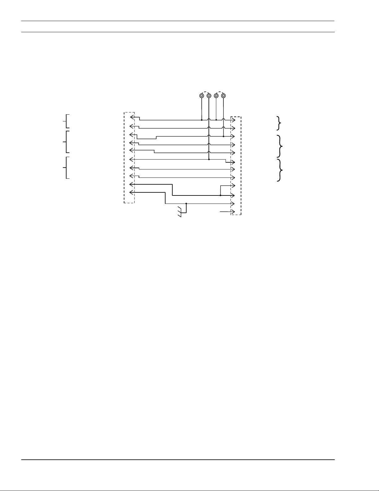
6.8 SmartFlow 2.5 Interface PCB Schematic (3 pages)
Proportional Valve Interface Schematic
V2PWR
V1PWR
P4
1
(RED)
1
A
V
L
V
3
E
+
2
V
4
L
O
T
H
A
R
S
S
N
E
3
E
V
AL
V
H
A
A
V
HARNESS
V
source file:
3
1
R
N
E
S
S
6
L
E
V
2
3
1
6
A
L
V
1
E
3
2
(WHITE)
VALVE 2 +24 VOLTS
(RED)
A
V
(WHITE)
(GREEN)
(RED)
A
V
(WHITE)
VALVE 1 P-SENSOR
(GREEN)
(BLACK)
V
AL
L
2
E
V
V
AL
E
V
L
1
L
A
V
VALVE GNDS
VALVE SHIELDS
S
10
V
E
3
S
E
T
P
T
P
-
S
V
E
P
T
2
+
4
E
V
1
T
P
9
.
8
N
S
E
R
O
7
2
S
E
T
6
.
S
T
L
O
V
5
4
T
E
S
3
.
2
1
135c001c.dxf (modified for SmartFlow 2.5
N.C.
P
1
V
L
A
V
E
2
E
V
L
V
A
3
VALVE 2 +24 VDC
4
VALVE 2 P-SENSOR
PROVISIONAL
5
L
V
V
A
E
6
E
A
V
L
V
7
V
L
A
V
E
PROVISIONAL
8
VALVE 1 SET PT.
4
2
C
D
V
9
10
4
2
V
DC
11
CHASSIS GROUND
12
3
4
+
2
V
T
E
S
3
S
2
E
T
V
1
2
4
+
-
1
P
E
S
G
R
O
U
G
RO
UND
CUT
C
D
H2O
.
T
P
2
/
N
-
H
3
5
/
i
A
r
P
T
.
D
C
S
N
O
R
2
O
N
D
6-10
SmartFlow 2.5

SECTION 6 TROUBLESHOOTING
Pressure Switch (PS) Interface Schematic
2
C1
0.1MFD
P
1
CUT WATER P-SENSOR +
2
CUT WATER P-SENSOR -
3
PRES. SW. 15 V. SOURCE (SR1)
4
PRES. SW. 24 V. SOURCE (SR2)
5
PS1 (N2 /ALT)
6
P
S
U
(
2
C
T
H
O
2
)
7
PS3 (O2)
2
G
H
N
O
O
I
L
C
1
(
S
F
8
P
9
2
V-Divide Arc Volts
V-Divide Work
1
O
)
P
PROVISIONAL
source file:
CUT WATER P-SENSOR +
CUT WATER P-SENSOR -
5
/
i
A
H
2
O
O
(
)
2
PS1
r
)
PS1
PS2
)
PS2
PS3
PS3
FS2
FS2
BUSS BAR
2
/
-
H
3
(
N
C
(
U
T
(COOLING H2O)
135c001c.dxf (modified for SmartFlow 2.5
5
1
2
3
4
5
6
7
8
1
2
6
P
JP1
JP2
JP3
Jumpers JP1 -- JP4
select either 24 vdc or
15 vdc input
JP4
requirements
1K 0.5W
CW
R1
R2
15K 8W
SmartFlow 2.5
6-11

SECTION 6 TROUBLESHOOTING
Solenoid Valve Interface Schematic
P
P7
AIR
1
2
AIR
3
N2
4
N2
H-35/Air
-
H
CUT H2O
CUT H2O
CUT H2O AUX
CUT H2O AUX
ARC START AC PWR
ARC START AC PWR
source file:
135c001c.dxf (modified for SmartFlow 2.5
5
6
3
5
/
i
A
r
7
8
9
10
O
2
11
O
2
12
1
2
8
P
RC1
RC2
RC3
RC4
RC5
RC6
RC7
N.C.
Note:
Alternate Gas can be H-35 or Air
3
1
SELECTOR VALVE COMMON
2
AIR
3
N2
120 VAC 50/60 HZ. 7 WATTS
4
5
/
A
H
3
-
5
CUT H2O
6
C
U
T
H
7
O
2
8
ARC START AC PWR
9
ARC START AC PWR
10
ALL SELECTOR
i
r
2
O
A
U
X
VALVES
6-12
SmartFlow 2.5

SECTION 6 TROUBLESHOOTING
6.9 SmartFlow 2.5 Secondary Shield Gas Proportional Valve Calibration
The Secondary Shield Gas (and Cutwater)
NOTICE
P3 P4
P1
S1, S2, S3, S4
P2
Cutwater/Secondary
Shield Proportional
Valve
Proportional valve is the only proportional
valve that can be calibrated.
Plasma Gas proportional valves are
calibrated by the valve manufacturer to
ESAB specifications. Do not attempt to
calibrate.
The following instructions are for calibrating single
or multiple station machines to ensure a
consistent value for the Cut Water/Shield
proportional valve. This calibration procedure will
ensure the SDP files developed in the factory
conform to the same screen values and output
pressures as factory settings.
These instructions are tested for PT19XLS
and PT-600 Secondary Shield only.
1. Calibrate the frequency of the proportional
valve using Pin2 to Pin3 for 300 Hz for gas and
water using P4 (potentiometer).
2. Check voltage on Pin2 to Pin3 on
Cutwater/Shield proportional valve. At 100 on
Vision Parameter Window for "Cut Water or
Shield" the voltage should be approximately 10
VDC.
3. Set shield gas regulator to 80 psi on the back
of the plumbing box with screen value for
"Cutwater/Shield" set to 100.
4. Check shield gas gauge (on front of plumbing
box) for max output pressure equal to about 32
psi. Adjust P3 (potentiometer) on proportional
valve board to maximum value by turning
clockwise until the pressure peaks out. Then
turn counterclockwise until the pressure begins
to drop. This will insure the valve is at the
maximum opening for the voltage.
5. Recheck shield input gas regulator is at 80 psi
at 100 on screen. Reset to 80 psi if necessary
and recheck for maximum output pressure of
32 psi.
SmartFlow 2.5
6-13

SECTION 6 TROUBLESHOOTING
P1 (potentiometer)
6. Set screen value for "Cut Water or Shield" to
20. Check voltage on Pins 2 to 3 on Cut
Water/Shield proportional valve. The voltage
should be approximately 2 volts. Check Shield
gas gauge for minimum output pressure equal
to 4 psi approximately (this is the first tick mark
on the gauge above the needle rest). Adjust P1
on proportional valve board to 4 psi. Use a
similar procedure to step 4) to reach a
consistent value on the gauge. This will result
in a minimum opening of the valve at low
settings.
7. Check the gauge pressure for Secondary
Shield set at 50 on the screen. This should be
approximately 14 psi on the plumbing box
gauge (adjust P2 to obtain 14-16 psi ).
8. Lower the inlet gas regulator to 60 psi with the
screen value set to 100. This should result in a
gauge pressure of approximately 22 psi. This
will insure the SDP files generated since
January 2000 will be consistent in the field.
6-14
SmartFlow 2.5

SECTION 7 REPLACEMENT PARTS
7.1 General
Always provide the serial number of the unit on
which the parts will be used. The serial number is
stamped on the unit nameplate.
7.2 Ordering
To ensure proper operation, it is recommended
that only genuine ESAB parts and products be
used with this equipment. The use of non-ESAB
parts may void your warranty.
Replacement parts may be ordered from your
ESAB Distributor or from:
ESAB Welding and Cutting Products
ATTN: Customer Service Department
PO Box 100545 Ebenezer Road
Florence, SC USA 29501-0545
Phone (843) 664-4405
(800) ESAB-123 (372-3123)
ESAB Cutting Systems - Canada
6010 Tomken Road
Mississauga, Ontario, Canada L5T 1X9
Phone (905) 670-0220
Fax (905) 670-4879
ESAB Cutting Systems GmbH
Robert-Bosch-Strasse 20
Postfach 1128
D-61184 Karben
Phone 011-49-6039-400
Fax 011-49-6039-403-02
http://www.esab.de
Be sure to indicate any special shipping
instructions when ordering replacement parts.
Refer to the Communications Guide located on
the last page of this manual for a list of customer
service phone numbers.
SmartFlow 2.5
7-1

SECTION 7 REPLACEMENT PARTS
7.3 Inside Right View – Smartflow 2.5 (w/o H-35 capability)
PN 0560935257 Replacement Parts (DISCONTINUED)
7-2
SmartFlow 2.5

SECTION 7 REPLACEMENT PARTS
SmartFlow 2.5 (without H-35 Capability) – Assembly P/N 0560935257 (DISCONTINUED)
Item
Number
1 0558001056 1 Manifold Assembly without H-35 proportional valve
2 0558001068 2 Valve Sentronic 0-6 bar Manifold Mount (Oxygen)
0558001282 4 O-Ring…Proportional valve 5mm ID X 1mm
0558001283 2 O-Ring…Proportional valve 4mm ID X 1mm
3 0558001066 5 Valve solenoid, 2 way series 2, 120vac 150 mopd 1/8 orifice
4 952920 2 Pressure Switch 50 psi non-adj
5 0558001064 1 Hose ¼ NPT M X ¼ NPT F X Swivel Ball 13.5" long
6 0558001063 1 Hose ¼ NPT M X ¼ NPT F X 10.75" long
7 0558001062 1 Hose ¼ NPT M X ¼ NPT F X 6" long
8 56998261 1 Valve Proportional Water Pulse Width Modulator
56997044 1 Valve Proportional Water 24VDC
9 0558001067 1 Hose ¼ NPT M X ¼ NPT F X 13.5" long
10 37538 1 Smartflow II Plumbing Box Assembly
Part Number Quantity Description
SmartFlow 2.5
7-3

SECTION 7 REPLACEMENT PARTS
7.4 Inside Right View – Smartflow 2.5 (w/ H-35 capability)
PN 0560935258 Replacement Parts
7-4
SmartFlow 2.5

SECTION 7 REPLACEMENT PARTS
SmartFlow 2.5 (with H-35 Capability) – Assembly P/N 0560935258
Item
Number
1 0558001061 1 Manifold Assembly with H-35 proportional valve
2 0558001065 1 Valve Sentronic 0-6 bar Manifold Mount (Fuel Gas Rated)
0558001282 2 O-Ring…Proportional valve 5mm ID X 1mm
0558001283 1 O-Ring…Proportional valve 4mm ID X 1mm
3 0558001066 6 Valve solenoid, 2 way series 2, 120vac 150 mopd 1/8 orifice
4 952920 3 Pressure Switch 50 psi non-adj
5 0558001064 1 Hose ¼ NPT M X ¼ NPT F X Swivel Ball 13.5" long
6 0558001063 1 Hose ¼ NPT M X ¼ NPT F X 10.75" long
7 0558001062 1 Hose ¼ NPT M X ¼ NPT F X 6" long
8 56998261 1 Valve Proportional Water Pulse Width Modulator
56997044 1 Valve Proportional Water 24VDC
Part Number Quantity Description
9 0558001067 1 Hose ¼ NPT M X ¼ NPT F X 13.5" long
10 37538 1 SmartFlow II Plumbing Box Assembly
11 0558001068 1 Valve Sentronic 0-6 bar Manifold Mount (Oxygen)
0558001282 2 O-Ring…Proportional valve 5mm ID X 1mm
0558001283 1 O-Ring…Proportional valve 4mm ID X 1mm
SmartFlow 2.5
7-5

SECTION 7 REPLACEMENT PARTS
7.5 Outside Front View – SmartFlow 2.5 Replacement Parts
1
AIR CURTAIN
60
2
CUT GAS
To Pilot Arc
Start Box
100
CUT WATER
100
AIR CURTAIN
CUT GAS
CUT WATER
7-6
6
5
4
3
SmartFlow 2.5

SECTION 7 REPLACEMENT PARTS
Item
Number
1 0558001060 1 Pressure Gauge 2½" 60 psi
2 0558001059 2 Pressure Gauge 2½" 100 psi
3 0558001054 1 Label Set
4 33053 1 Strain Relief 2" Torch
5 0558001057 1 Knurled Nut-Fiber Optic Cable Holder
6 0558001058 1 (Internal) Fiber Optic Cable Assembly for spark viewing.
Part Number Quantity Description
SmartFlow 2.5
7-7

SECTION 7 REPLACEMENT PARTS
7.6 Inside Left View – SmartFlow 2.5 Replacement Parts
C1
R2
P2
P3
P1
2
1
7-8
7
6
5
4
3
SmartFlow 2.5

SECTION 7 REPLACEMENT PARTS
Item
Number
1 0558001055 1 High Freq Arc Starter Box
2 0558001050 1 Printed Circuit Board
3 0558001053 1 Buss Bar Block Assembly
4 0558001051 1 Check Valve ¼ NPT M X ¼ NPT M
5 0558001049 1 Hose ¼ NPT F X ¼ NPT F X 7.5" Long
6 0558001052 1 Hose ¼ NPT M X ¼ NPT M X 11" Long
7 63383 1 Flow Switch 1.0 GPM
0558001051 1 Check Valve ¼ NPT M X ¼ NPT M
Part Number Quantity Description
SmartFlow 2.5
7-9

SECTION 7 REPLACEMENT PARTS
7.7 Outside Back View – SmartFlow 2.5 Replacement Parts
1
NITROGEN
OXYGEN
AIR
CUT WATER
4
COOLING WATER
OUT IN
7-10
2
3
SmartFlow 2.5

SECTION 7 REPLACEMENT PARTS
Item
Number
1 0558001047 4 Grommet Cable Clamp “Small” 14-15mm
0558001048 3 Grommet Cable Clamp “Large” 27-28mm
2 0558001054 Ref Label Set (Same set as shown on front parts)
Part Number Quantity Description
3 56997206 3
4 56998133
Not
shown
0560988406
As
required
1 per
filter
Muffler Exhaust Brass
25 micron gas filter with bowl guard
Replacement filter ELEMENT for 56998133
1
/8 NPT Male
SmartFlow 2.5
7-11

SECTION 7 REPLACEMENT PARTS
This page intentionally left blank.
7-12
SmartFlow 2.5

REVISION HISTORY
• 4/19/07 – corrected labeling shown in Replacement parts section - proportional valves.
Author – dp.
SmartFlow 2.5
 Loading...