

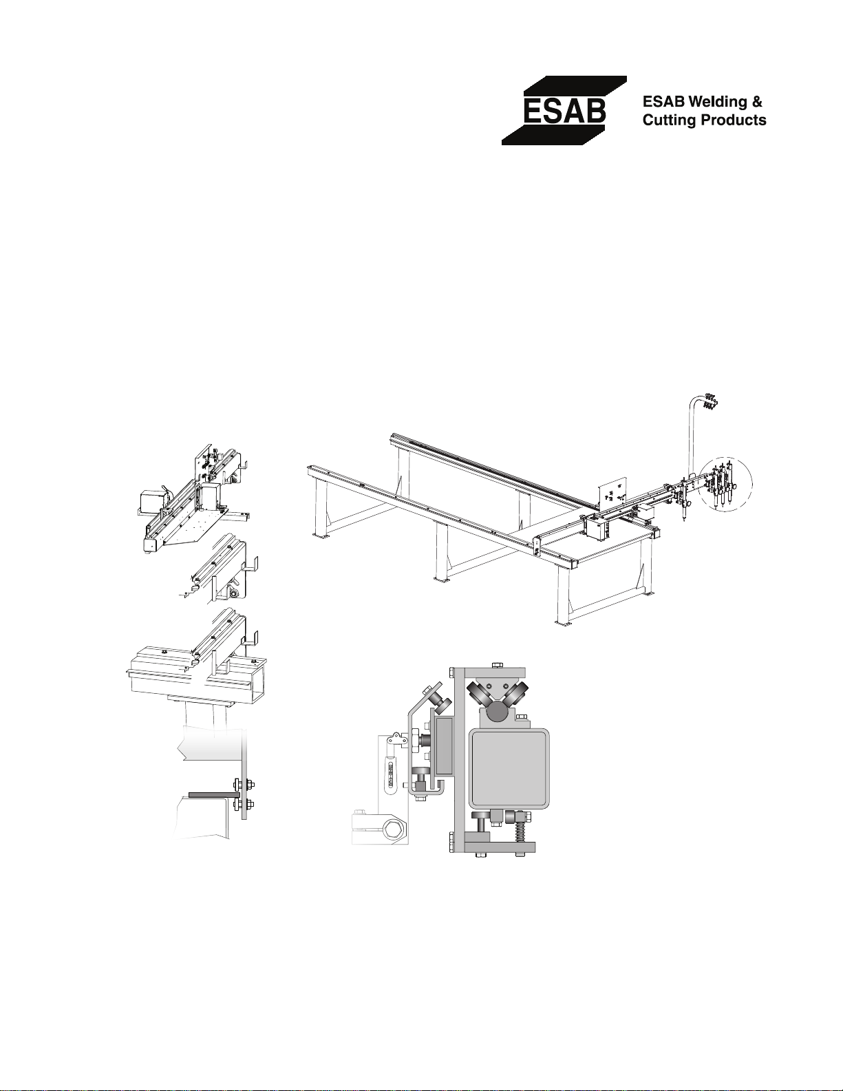
Silhouette 1000
OP TI ON AL T OR CH
ST AT ION S
Cantilever Cutting Machine
Form Number 0558006575
Date: 12-01-06
Safety
Installation
Operation
Maintenance
Replacement Parts

The equipment described in this manual is
potentially hazardous. Use caution when installing,
operating and maintaining this equipment.
The purchaser is solely responsible for the safe
operation and use of all products purchased,
including compliance with OSHA and other
government standards. ESAB Cutting Systems
has no liability for personal injury or other
damage arising out of the use of any product
manufactured or sold by ESAB. See standard
ESAB terms and conditions of sale for a specic
statement of ESAB’s responsibilities and
limitations on its liability.
ESAB Cutting Systems is not responsible for
any errors that may appear in this document.
Information in this document is subject to change
without notice.
This manual is ESAB Part No. 0558006575
This manual is for the convenience and use of the
cutting machine purchaser. It is not a contract
or other obligation on the part of ESAB Cutting
Systems.
SAB Cutting Systems, 2006
* E
Printed In U.S.A.

Revision History
12/01/06: Original: Replaces manual number 51227
with part revisions, additional information and new
illustrations.
Preface
This machine is a cantilevered gantry cutting
machine manufactured by ESAB Cutting Systems of
Florence, South Carolina. It may be equipped with
either oxy-fuel or plasma cutting equipment. It is
designed to provide years of dependable, accurate,
repeatable part cutting, with a high degree of
reliability, ease of service and operation.
There are optional features and congurations
available. However, not all options described in this
manual are present on all machines. In addition,
more capabilities and features may be added in the
future, which are not covered in this manual. ESAB
Cutting Systems reserves the right to change or add
features and capabilities without notice. Before
operating the machine, one should become familiar
with this manual in its entirety, with special attention
to the SAFETY section.


Table of Contents
Safety
TOC
Silhouette 1000 Contents
Introduction ................................................................................................................
General Cutting Machine Safety .................................................................................................................
Electrical Grounding ................................................................................................................
Operating A Cutting Machine ................................................................................................................
Working with Plasma Cutting Equipment ..................................................................................................... 8
Working with Oxy-Fuel Gas Cutting Equipment ......................................................................................... 14
Working with Gas Control and Supply Systems .......................................................................................... 16
Service Precautions ................................................................................................................
Welding On and Around Machine ................................................................................................................
Introduction .................................................................................................................
Safety References ..................................................................................................................
Domestic .................................................................................................................
International ................................................................................................................
Specications
Outline Dimensions .................................................................................................................
Performance .................................................................................................................
Requirements .................................................................................................................
............................................. 1
............................. 4
........... 5
.............................. 19
...................................... 21
................................. 21
............................................ 22
...................................... 23
.............................. 29
........................................... 30
......................................... 30
...... 2
... 20
Capacities ..................................................................................................................
Installation
Receipt of Components .................................................................................................................
Site Preparation ................................................................................................................
Location of the Machine ..................................................................................................................
Foundation ..................................................................................................................
Utility Requirements .................................................................................................................
Electric Power ..................................................................................................................
Grounding ................................................................................................................
Gas Supplies .................................................................................................................
Installation of Components .................................................................................................................
Installation of pedestals and rails. ..............................................................................................................43
Forklift Technique .................................................................................................................
Mounting Main Beam on Rails .................................................................................................................
Strongback Technique ................................................................................................................
Torch Station Mounting .................................................................................................................
Table of Contents
................................................ 31
...................................... 35
............................................. 37
............................ 38
.................................. 38
.......................................... 38
..................................... 39
........................... 47
...................... 34
.................... 36
............... 43
.......... 48
................... 49
..................... 59

TOC Table of Contents
Torch Squaring ........................................................................................................................................................ 60
Tracer Mount and Leveling .................................................................................................................
Interconnection of components. ..................................................................................................................
Water Spray Installation .................................................................................................................
Automatic Ignitor .................................................................................................................
Introduction .................................................................................................................
Ignitor installation .................................................................................................................
Ignitor Wiring Schematic .................................................................................................................
Ignitor Setup .................................................................................................................
Setup Procedure...............................................................................................................................................71
Preparation for Initial Power-up ..................................................................................................................
Purging Lines .................................................................................................................
Mechanical Check ..................................................................................................................
Operation
Introduction ................................................................................................................
HL-90 Tracer ..................................................................................................................
Template Preparation .................................................................................................................
Introduction .................................................................................................................
...................................... 67
..................................... 70
.................................... 72
............................................. 75
........................................... 76
...................................... 78
...................... 65
................................. 67
.......................... 67
.......................... 73
.......................... 78
................ 61
.... 63
............. 69
...... 72
Template Guidelines .................................................................................................................
Drawing Materials .................................................................................................................
Machine Operation .................................................................................................................
Introduction .................................................................................................................
Straight Line Cutting (without template) ................................................................................................ 81
Tracer Controlled Cutting (with template) ..............................................................................................82
Lost Cut Procedure .................................................................................................................
Kerf Compensation ..................................................................................................................
Notes on Pattern and Kerf Requirements...................................................................................................... 89
Torch Carriage Positioning .................................................................................................................
...................................... 81
...................... 79
........................... 80
............................... 81
......................... 83
.............................. 84
................. 90
Table of Contents

Table of Contents
Silhouette 1000 Maintenance
TOC
General Information .................................................................................................................
Daily Inspection and Maintenance. ................................................................................................................. 92
Periodic Inspection and Maintenance ............................................................................................................ 94
Lubrication .................................................................................................................
Rail System .................................................................................................................
Tracing Table ..................................................................................................................
Gas Supply System................................................................................................................................................. 102
Solenoid Disassembly Procedure ............................................................................................................... 104
Electrical System ..................................................................................................................
Motorized Lift ................................................................................................................
Description .................................................................................................................
Motorized Lift Maintenance ................................................................................................................
.............................................. 95
............................................... 96
............................. 91
.......................................... 97
................................... 105
......................................... 106
........................................ 106
............... 107
Parts Section
Introduction
General Information .................................................................................................................
Ordering Information .................................................................................................................
Silhouette 1000, Basic Machine, 4 and 6FT.
0560938838 Rev OR...............................................................................................................................................111
Main Beam
2235502 Rev1 .................................................................................................................
Rail System Assembly
0560938839 Rev 1 ................................................................................................................
Rail System Master Rail
0560938843 Rev 1 ..................................................................................................................
Rail System Floater Rail
0560938840 Rev 1 .................................................................................................................
Master Carriage
0560938837 Rev 1 .................................................................................................................
Bearing Block Assembly
51216 Rev OR .................................................................................................................
........................................... 121
............................. 109
.......................... 110
.......................................... 114
.................................. 116
................................ 117
................................. 119
................................. 120
Station Control Assembly
2235503 Rev 1 ..................................................................................................................
Table of Contents
........................................ 122

TOC Table of Contents
Motorized Lift
2237347 Rev 3 ..................................................................................................................
Manifold Support Assembly
40201829 Rev 1 .................................................................................................................
Torch Bar Assembly
40901329 Rev 1 .................................................................................................................
Drive Motor Assembly-Rail
41001289 Rev 1 .................................................................................................................
Manual Torch Station
41001689 Rev 1 ..................................................................................................................
Torch Holder
52675 Rev 1 ..................................................................................................................
Tracing Table Assembly
4113001 Rev 1 .................................................................................................................
Budget Ignitor Assembly
57000323 Rev A....................................................................................................................................................... 134
Torch Ignitor Module
69972 Rev OR ..................................................................................................................
........................................ 123
...................................... 125
...................................... 126
....................................... 128
...................................... 130
............................................. 132
......................................... 133
......................................... 135
Torch Ignitor Control Module
69973 Rev 1 .................................................................................................................
Ignition Control Box
66407 Rev B ..................................................................................................................
Ignitor J-Box and Wiring Diagram
66412 Rev OR .................................................................................................................
Motorized Station Control Box
66421 Rev OR .................................................................................................................
Oxygen Pierce Rate Control Assembly
0560939141 Rev 2 .................................................................................................................
Oxygen Pierce Rate Control Box
0560940441 Rev 1 .................................................................................................................
............................................. 136
............................................ 137
.......................................... 138
.......................................... 140
.................................. 6-142
................................. 6-144
Table of Contents
SAFETY
DANGER
WARNING
CAUTION
CAUTION
NOTICE
Safety
SECTION 1
Safety
Introduction
The process of cutting metals with oxy-fuel or
plasma equipment provides industry with a
valuable and versatile tool. ESAB cutting machines
are designed to provide both operation safety
and eciency. However, as with any machine
tool, sensible attention to operating procedures,
precautions, and safe practices is necessary to
achieve a full measure of usefulness. Whether
an individual is involved with operation,
servicing, or as an observer, compliance with
established precautions and safe practices must
be accomplished. Failure to observe certain
precautions could result in serious personnel
injury or severe equipment damage. The following
precautions are general guidelines applicable when
working with cutting machines. More explicit
precautions pertaining to the basic machine and
accessories are found in the instruction literature.
For a wide scope of safety information on the eld of
cutting and welding apparatus, obtain and read the
publications listed in the Recommended References.
The following words and symbols are used
throughout this manual. They indicate dierent
levels of required safety involvement.
Used to call attention to immediate
hazards which if not avoided, will result in
serious personal injury or death.
Used to call attention to potential hazards
that could result in personal injury or loss
of life.
Used to call attention to hazards that
could result in minor personal injury or
equipment damage.
Used to call attention to minor hazards to
equipment.
Used to call attention to important
installation, operation or maintenance
information not directly related to safety
hazards.
Safety Section
1

SAFETY
WARNING
SECTION 1 Safety
General Cutting Machine Safety
Machine Starts Automatically.
This equipment moves in various
directions and speeds. Moving machinery
can crush.
Only qualied personnel should
•
operate or service equipment.
Keep all personnel, materials, and
•
equipment not involved in production
process clear of entire system area.
Keep gear racks and rails clear of
•
debris or obstructions, such as tools or
clothing.
Fence o entire work cell to prevent
•
personnel from passing through area
or standing in the working envelope of
the equipment.
Post appropriate WARNING signs
•
at every work cell entrance. Follow
lockout procedure before servicing.
2
Safety Section

SAFETY
Safety
WARNING
WARNING
SECTION 1
Read and Understand This
Operator’s Manual Before using
machine.
Failure to follow operating instructions
could result in death or serious injury.
Read entire procedure before
•
operating or performing any system
maintenance.
Special attention must be given to all
•
hazard warnings that provide essential
information regarding personnel
safety and/or possible equipment
damage.
All safety precautions relevant to
•
electrical equipment and process
operations must be strictly observed
by all having system responsibility or
access.
Read all safety publications made
•
available by your company.
Read and Understand All Safety
Warning Labels On Machine.
Failure to follow safety warning label
instructions could result in death or
serious injury.
Refer to operator’s manual for additional
safety information.
Safety Section
3

SAFETY
CAUTION
SECTION 1 Safety
WARNING
Electrical Grounding
Electrical grounding is imperative for proper
machine operation and SAFETY. Refer to this
manual’s Installation section for detailed grounding
instructions.
Electric Shock Hazard.
Improper grounding can cause severe
injury or death.
Machine must be properly grounded
before put into service.
Improper Grounding Can Damage
Machine and Electrical Components.
Machine must be properly grounded
before put into service.
Cutting table must be properly grounded
to a good Earth ground rod.
4
Safety Section

SAFETY
WARNING
WARNING
WARNING
Safety
SECTION 1
Operating A Cutting Machine
Crush Hazard.
Moving machine can crush.
Machine moves automatically.
Stay clear of rails and cutting table
•
during operation.
Follow lockout procedure before
•
servicing.
Flying Debris and Loud Noise
Hazards.
Hot spatter can burn and injure eyes.
Loud noise can injure ears.
Wear goggles to protect eyes from
•
burns and ying debris generated
during operation.
Wear ear protection as required for
•
cutting various materials.
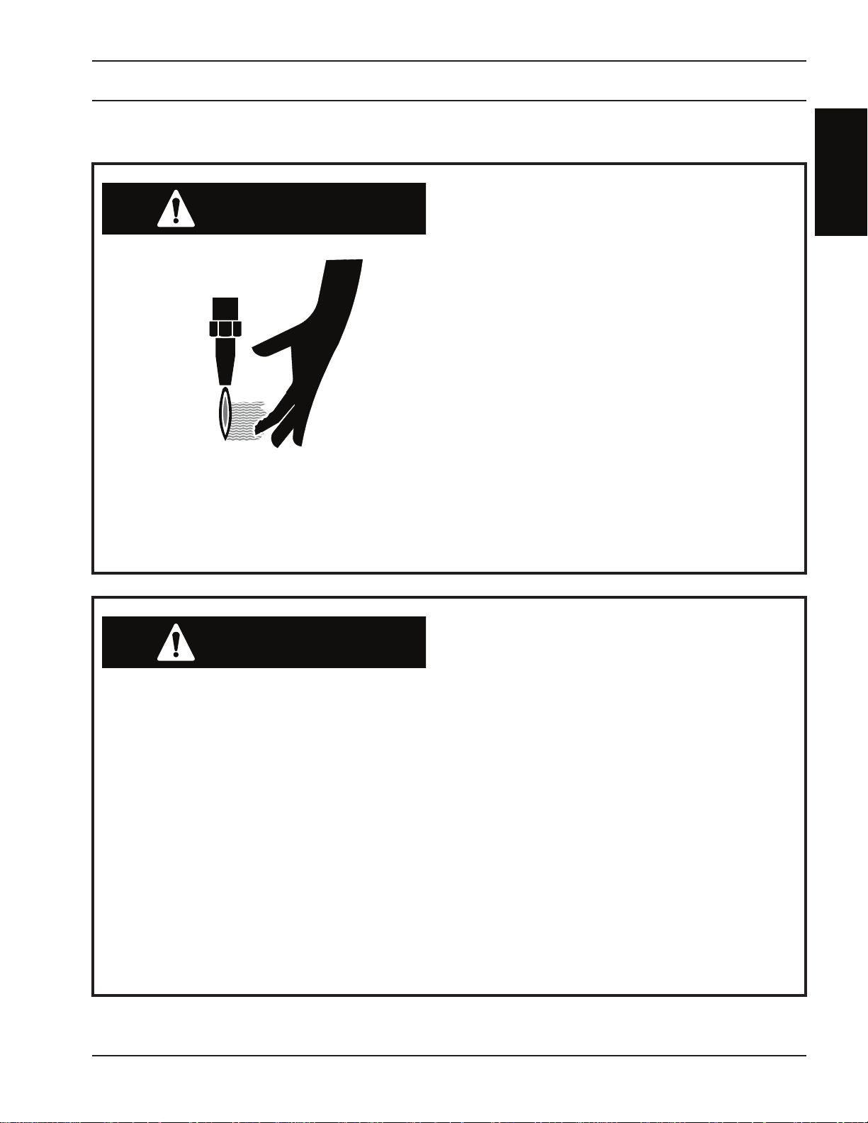
Burn Hazard.
Hot metal can burn.
•
Do not touch metal plate or parts
•
immediately after cutting. Allow metal
time to cool, or douse with water.
Do not touch plasma torch
•
immediately after cutting. Allow torch
time to cool.
Safety Section
5

SAFETY
WARNING
WARNING
SECTION 1 Safety
Crush Hazard.
Moving parts can cut and crush.
•
Keep hands clear of drive gears.
•
Do not operate with any protective
•
covers removed.
Follow lockout procedure before
•
servicing.
Hazardous Voltages.
Electric shock can kill.
Do not operate with any protective
•
covers removed or electrical
component boxes open.
Follow lockout procedures before
•
servicing.
6
Safety Section

SAFETY
WARNING
WARNING
Safety
SECTION 1
Pinch Hazard.
Moving vertical slides can crush or
•
pinch.
Keep hands clear of torch and slide
•
during operation.
Pinch Hazard.
Moving carriages can crush or pinch.
•
Keep hands clear of carriages during
•
operation.
Safety Section
7

SAFETY
WARNING
SECTION 1 Safety
Working with Plasma Cutting
Equipment
Hazardous Voltages.
Electric Shock Can Kill.
Do NOT touch plasma torch, cutting
•
table or cable connections during
plasma cutting process.
Always turn power o to plasma power
•
supplies before touching or servicing
plasma torch.
Always turn power o to plasma power
•
supplies before opening or servicing
plasma plumbing or ow control box.
Do not touch live electrical parts.
•
Keep all panels and covers in place
•
when machine is connected to power
source.
Insulate yourself from workpiece and
•
electrical ground: wear insulating
gloves, shoes and clothing.
Keep gloves, shoes, clothing, work
•
area, and equipment dry.
8
Safety Section

SAFETY
Safety
WARNING
SECTION 1
Toxic Fume Hazard.
The cutting process can produce
poisonous fumes and toxic gases.
Certain chlorinated solvents decompose
and form phosgene gas when exposed to
ultraviolet radiation.
Do not cut metal or painted metals
containing zinc, lead, cadmium or
beryllium unless fume removal equipment
is installed and operating properly.
Keep cutting area well ventilated.
•
Wear proper breathing mask when
•
cutting galvanized metal and use
proper ventilation and fume removal
methods.
Insure chlorinated solvents are not in
•
cutting area.
Safety Section
9

SAFETY
WARNING
SECTION 1 Safety
WARNING
Radiation Hazard.
Arc rays can injure eyes and burn skin.
•
Wear correct eye and body protection.
•
Wear dark safety glasses or goggles
•
with side shields. Refer to following
chart for recommended lens shades
for plasma cutting:
Arc Current Lens Shade
Up to 100 Amps Shade No. 8
100-200 Amps Shade No. 10
200-400 Amps Shade No. 12
Over 400 Amps Shade No. 143.
Replace glasses/goggles when lenses
•
are pitted or broken.
Warn others in area not to look directly
•
at the arc unless wearing appropriate
safety glasses.
Prepare cutting area to reduce
•
reection and transmission of
ultraviolet light.
Paint walls and other surfaces with
•
dark colors to reduce reections.
Install protective screens or curtains to
•
reduce ultraviolet transmission.
Noise hazard.
Noise from plasma arc can damage
hearing.
10
Safety Section
SAFETY
WARNING
CAUTION
Safety
SECTION 1
Fume Hazard.
Fumes and gases generated by the plasma
cutting process can be hazardous to your
health.
Do NOT breathe fumes.
•
Do not operate plasma torch without
•
fume removal system operating
properly.
Use additional ventilation to remove
•
fumes if necessary.
Use approved respirator if ventilation
•
is not adequate.
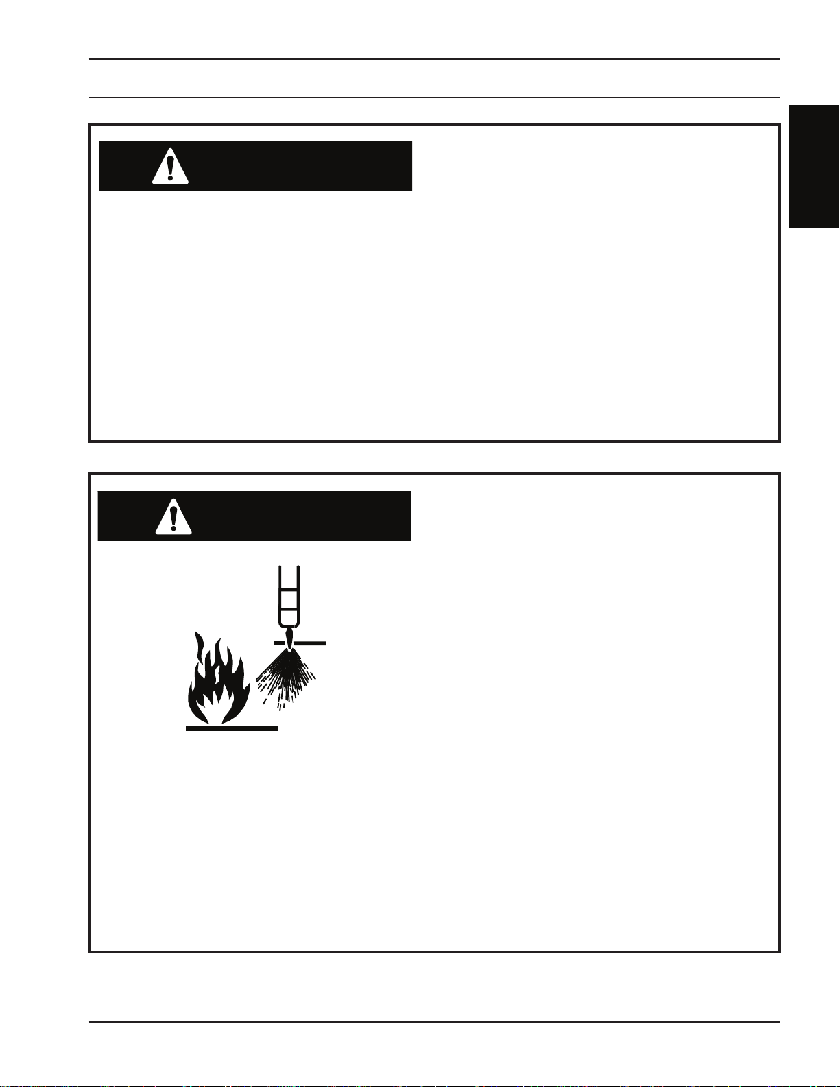
Spark Hazard.
Heat, spatter, and sparks cause re and
burns.
Do not cut near combustible material.
•
Do not cut containers that have held
•
combustibles.
Do not have on your person any
•
combustibles (e.g. butane lighter).
Pilot arc can cause burns. Keep torch
•
nozzle away from yourself and others
when activating plasma process.
Wear correct eye and body protection.
•
Wear gauntlet gloves, safety shoes and
•
hat.
Wear ame-retardant clothing that
•
covers all exposed areas.
Wear cuess trousers to prevent entry
•
of sparks and slag.
Safety Section
11

SAFETY
SECTION 1 Safety
WARNING
Hydrogen Explosion Hazard.
Hydrogen explosions can cause personal
injury or death.
Hydrogen can create explosive gas
pockets in the water table. These pockets
will explode when ignited by sparks or the
plasma arc.
Before cutting, be aware of possible
•
hydrogen sources in the water table
– molten metal reaction, slow chemical
reaction and some plasma gases.
Explosive gas pockets accumulate
•
underneath the cutting plate and
inside the water table.
Clean slag (especially ne particles)
•
from bottom of table frequently. Rell
table with clean water.
Do not leave plate on table overnight.
•
If water table has not been used for
•
several hours, vibrate or jolt it to break
up hydrogen pockets before laying
plate on the table.
If possible, change water level between
•
cuts to break up hydrogen pockets.
Maintain water pH level near 7
•
(neutral).
Programmed part spacing should be
•
a minimum of twice the kerf width to
ensure material is always under the
kerf.
If cutting underwater, aerate water
•
under plate with compressed air to
prevent hydrogen pockets.
12
If cutting above water, use fans to
•
circulate air between plate and water
surface.
Safety Section

SAFETY
Safety
WARNING
SECTION 1
Explosion Hazard.
Certain molten aluminum-lithium (Al-Li)
alloys can cause explosions when plasma
cut with water.
Do not plasma cut the following Al-Li
alloys with water:
Alithlite (Alcoa) X8192 (Alcoa)
Alithally (Alcoa) Navalite (US Navy)
2090 Alloy (Alcoa) Lockalite (Lockhead)
X8090A (Alcoa) Kalite (Kaiser)
X8092 (Alcoa) 8091 (Alcan)
These alloys should only be dry cut on a
dry table.
DO NOT dry cut over water.
DO NOT water injection cut.
Contact your aluminum supplier for
additional safety information regarding
hazards associated with these alloys.
Safety Section
13
SAFETY
WARNING
WARNING
SECTION 1 Safety
Working with Oxy-Fuel Gas
Cutting Equipment
Electric Shock Hazard.
Automatic torch igniters can cause
electrical shock.
Never touch an oxy-fuel cutting torch
during an automatic ignite sequence.
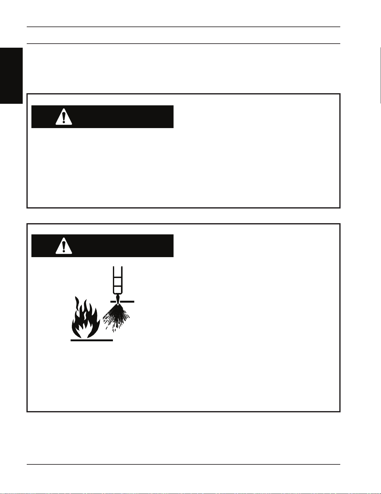
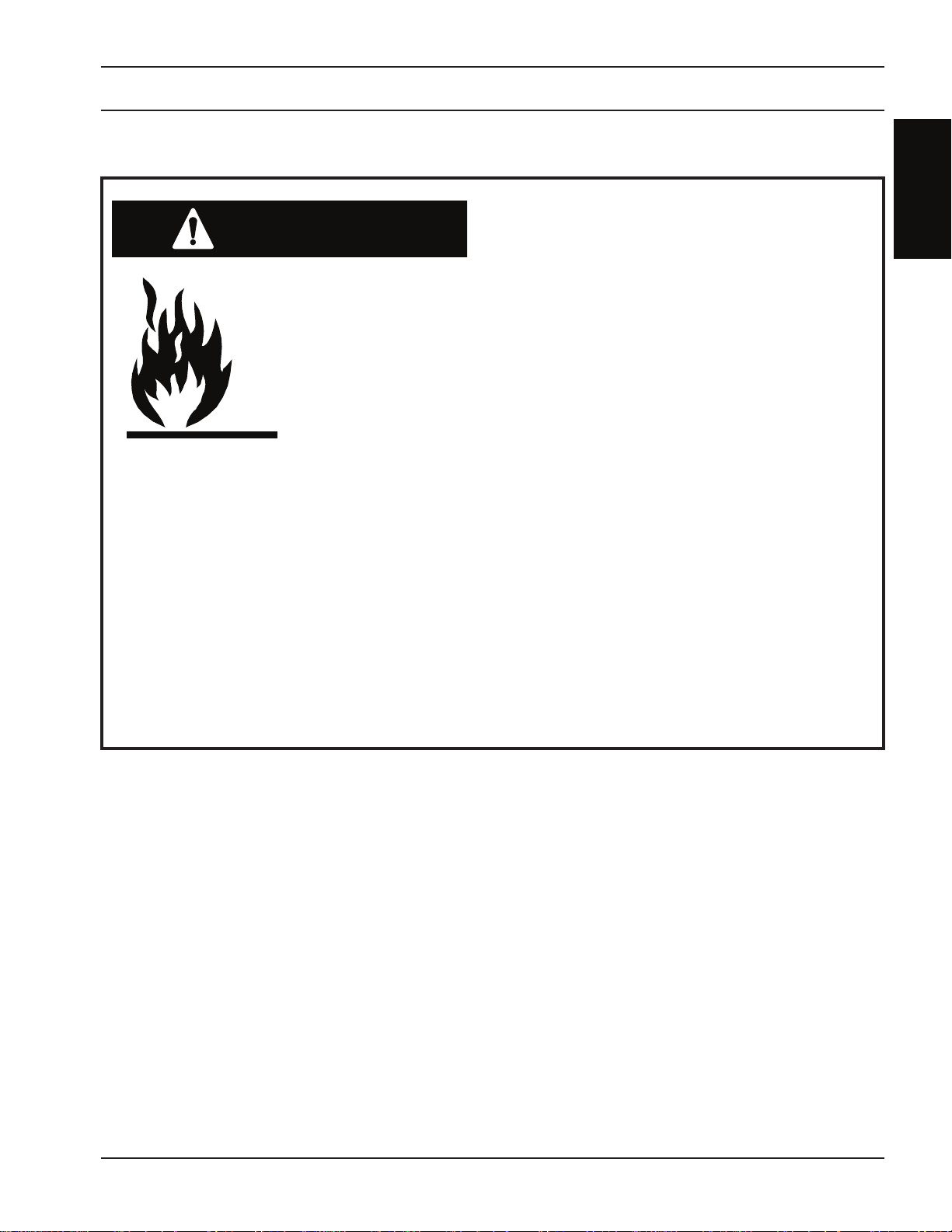
Spark Hazard.
Heat, spatter, and sparks cause re and
burns.
Do not cut near combustible material.
•
Do not cut containers that have held
•
combustibles.
Do not have on your person any
•
combustibles (e.g. butane lighter).
Wear correct eye and body protection.
•
Wear gauntlet gloves, safety shoes and
•
hat.
Wear ame-retardant clothing that
•
covers all exposed areas.
Wear cuess trousers to prevent entry
•
of sparks and slag.
14
Safety Section
SAFETY
WARNING
WARNING
Safety
SECTION 1
Burn Hazard.
Oxy-fuel torch ames can cause severe
burns.
Keep hands clear of oxy-fuel torches
•
during automatic ignite sequence.
Always conrm that no one is near oxy-
•
fuel torches before starting an ignite
sequence or starting a program that
initiates an ignite sequence.
Never work on an oxy-fuel cutting
•
torch while machine is executing a
program, or while someone is near
machine’s control console. They could
accidentally start an ignite sequence
or a program that initiates an ignite
sequence.
Explosion hazard.
Oxy-fuel torches can create explosive
gas pockets if owing gas is not burned.
These pockets can explode when torch is
ignited.
Never leave gases turned on if a torch
•
fails to ignite.
If un-ignited gas has been owing from
•
a torch more than a few seconds, allow
gas time to dissipate before re-igniting
the torch.
Explosive gas mixtures can accumulate
•
underneath plate and inside cutting
table. Use fans to dissipate any
possible gas pockets if un-ignited gas
has been owing into cutting table.
Safety Section
15

SAFETY
WARNING
SECTION 1 Safety
Working with Gas Control and
Supply Systems
Explosion and Fire Hazard.
Ordinary materials can explode and burn
in the presence of oxygen.
Keep all equipment clean and in good
•
operating condition.
Keep entire work area free from oil,
•
grease, and other combustibles.
Do not purge lines close to an ignition
•
source (i.e., ame or cigarette),
towards a person, or near clothing.
Clean all parts used to repair or replace
•
oxygen systems. They MUST be oil free.
Never use oxygen as a substitute for
•
compressed air to “dust” clothing,
work area, or pressure testing.
Never allow oil, grease, hydrocarbons,
•
or similar organic materials to come
in contact with oxygen or oxygenfuel gas equipment. Oxygen-fuel
gas apparatus does not require
lubrication.
Never use compressed air for blowing
•
out oxygen-fuel gas passages.
Compressed air contains oil that can
burn.
Always refer to oxygen by its proper
•
name - Oxygen. Never call oxygen
“air” which could be confused with
compressed air.
16
Safety Section
SAFETY
WARNING
Safety
SECTION 1
Explosion and Fire Hazard.
Oxygen and fuel gas mixtures can explode
and burn.
Keep all equipment clean and in good
•
operating condition.
Do not purge lines close to an ignition
•
source (i.e., ame or cigarette),
towards a person, or near clothing.
Avoid or ventilate any work areas that
•
might accumulate leaking gas.
Isolate cutting area to protect yourself
•
and others from heat, ame, sparks,
and hot slag.
Always identify fuel-gas by its proper
•
name. Generally fuel-gas used will
be acetylene, natural gas (usually
methane), or liquid petroleum (LP)
gases propane and butane. All
personnel should be aware of gas type
and characteristics being used.
Safety Section
17

SAFETY
SECTION 1 Safety
WARNING
Explosion Hazard.
Compressed gas can explode.
Before using machine, check for leaks
•
at gas connections on all regulators,
valves, and torches.
Open gas valves slowly, and shut
•
o when machine is inactive for
an extended time. Also, bleed line
pressure when machine is inactive for
an extended time.
Close source valves before servicing
•
any oxygen or fuel-gas lines,
connections, ttings, or regulators.
Bleed regulators completely when
•
changing gas cylinders. De-pressurize
system before performing any
maintenance or disassembly.
Secure all cylinders to prevent falling.
•
Never disconnect any part of system
•
that is under pressure.
Periodically check all ttings for leaks,
•
cables and hoses for wear, corrosion
or deterioration. Protect supply lines
and cables from damage. Do not drive
heavy equipment over them.
18
Safety Section

SAFETY
Safety
CAUTION
CAUTION
SECTION 1
Service Precautions
Establish and Adhere to Preventive
Maintenance.
A composite program can be established
from recommended schedules in the
instruction literature.
Avoid leaving test equipment or hand
tools on machine. Severe electrical
or mechanical damage could occur to
equipment or machine.
Extreme caution should be used when
probing circuitry with an oscilloscope or
voltmeter.
Although many steps have been taken
to protect integrated circuits, they are
susceptible to overvoltage damage.
Test probes should be connected while
machine power is o to prevent accidental
shorting of components.
Be thorough when handling electronic
components. When nished servicing,
conrm that all circuit boards are securely
seated in sockets, all cables are properly
connected, all cabinets are closed and
locked, all guards and covers are replaced.
Never plug or unplug a printed
circuit board while machine power is
on. Instantaneous surges of voltage
and current can damage electronic
components.
Never trace wiring with buzzer or light.
Use an ohm meter or logic probe. When
tracing circuits make certain that tracing
currents do not damage solid-state
devices.
Safety Section
19

SAFETY
CAUTION
SECTION 1 Safety
Welding On and Around
Machine
Special precautions must be observed
if any arc welding is performed on this
machine.
Failure to observe the following
precautions can result in large induced
currents causing severe damage to
electronic components in machine control
system. Machine damage caused by
improper welding practices is considered
abuse and voids certain warranty
provisions.
Disconnect all cables to Relay Box,
•
Numerical Controller, Tracer System,
and Control Console.
Always connect welder ground cable
•
directly to the part to be welded and as
close to the weld point as possible.
Keep the current path between the
•
ground point and the weld as short as
possible.
Never connect the ground to points
•
where the welding current path could
include moving parts or bolted joints.
This can result in a high resistance
circuit that could divert high current
into the control system and damage
mechanical components (e.g.
bearings).
20
Safety Section

SAFETY
Safety
SECTION 1
Safety References
Introduction
The following nationally recognized publications
on safety in welding and cutting operations are
recommended. These publications have been
prepared to protect persons from injury or illness
and to protect property from damage, which could
result from unsafe practices. Although some of
these publications are not related specically to this
type of industrial cutting apparatus, the principles of
safety apply equally.
Safety Section
21

SAFETY
SECTION 1 Safety
Domestic
“Precautions and Safe Practices in Welding and
•
Cutting with Oxygen-Fuel Gas Equipment,” Form
2035. ESAB Cutting Systems.
•
“Precautions and Safe Practices for Electric
Welding and Cutting,” Form 52-529. ESAB
Cutting Systems.
•
“Safety in Welding and Cutting” - ANSI Z 49.1,
American Welding Society, 2501 NW 7th Street,
Miami, Florida, 33125.
•
”Recommended Safe Practices for Shielded
Gases for Welding and Plasma Arc Cutting” - AWS
C5.10-94, American Welding Society.
•
“Recommended Practices for Plasma Arc
elding” - AWS C5.1, American Welding Society.·
W
“Recommended Practices for Arc Cutting” - AWS
C5.2, American Welding Society.
•
“Safe Practices” - AWS SP, American Welding
Society.
•
“Standard for Fire Protection in Use of Cutting
and Welding Procedures” - NFPA 51B, National
Fire Protection Association, 60 Batterymarch
Street, Boston, Massachusetts, 02110.
•
“Standard for Installation and Operation of
Oxygen - Fuel Gas Systems for Welding and
Cutting” - NFPA 51, National Fire Protection
Association.
•
“Safety Precautions for Oxygen, Nitrogen,
Argon, Helium, Carbon Dioxide, Hydrogen, and
Acetylene,” Form 3499. ESAB Cutting Systems.
Obtainable through your ESAB representative or
local distributor.
•
“Design and Installation of Oxygen Piping
Systems,” Form 5110. ESAB Cutting Systems.
•
“Precautions for Safe Handling of Compressed
Gases in Cylinders”, CGA Standard P-1,
Compressed Gas Association.
Literature applicable to safe practices in welding and
cutting with gaseous materials is also available from
the Compressed Gas Association, Inc., 500 Fifth Ave.,
New York, NY 10036.
22
Safety Section
 Loading...