

ESAB PT-20AMX Plasmarc Cutting Torch and PT-21AMX Plasmarc Cutting Torch Installation manual / Instruction manual

December 2006
Installation, Operation and Maintenance
PT-20AMX Plasmarc Cutting Torch
and
PT-21AMX Plasmarc Cutting Torch
F15-778

The equipment described in this manual is
potentially hazardous. Use caution when installing,
operating and maintaining this equipment.
Purchaser is solely responsible for the safe
operation and use of all products purchased,
including compliance with OSHA and other
government standards. ESAB Cutting
Systems has no liability for personal injury or
other damage arising out of the use of any
product manufactured or sold be ESAB. See
standard ESAB terms and conditions of sale
for a specific statement of ESAB’s
responsibilities and limitations on its liability.
ESAB Cutting Systems first priority is total
customer satisfaction. We constantly look for
ways to improve our products, service and
documentation. As a result, we make
enhancements and/or design changes as
required. ESAB makes every possible effort to
ensure our documentation is current. We
cannot guarantee that each piece of
documentation received by our customers
reflects the latest design enhancements.
Therefore, the information contained in this
document is subject to change without notice.
This manual is ESAB Part Number
This manual is for the convenience and use of the
cutting machine purchaser. It is not a contract or
other obligation on the part of ESAB Cutting
Systems.
F15-778
Printed in U.S.A.
© ESAB Cutting Systems, 2002

Table of Contents
Page
Safety
Introduction ........................................................................................... 1
Safety Notations And Symbols ................................................................ 2
General Safety Information ...................................................................... 3
Installation Precautions............................................................................ 3
Electrical Grounding................................................................................ 5
Operating A Plasma Cutting Machine ...................................................... 5
Service Precautions ................................................................................ 9
Safety References................................................................................... 10, 11, 12
I. Description Introduction .....................................................................
II. Accessories.......................................................................................... 14
III. Installing Front End Parts.................................................................. 16
IV. Operation – Cutting Parameters....................................................... 20
V. Maintenance........................................................................................ 21
A. General.............................................................................................
B. Dirt or Contamination........................................................................
C. Loose Consumables.........................................................................
D. Damage Caused By Loose Parts and Torch Over Heating...............
E. Consumables – Removal and Replacement.....................................
F. Measuring Torch Gas Flows.............................................................
G. Removal and Replacement of Torch Body.......................................
PT-20AMX Torch...............................................................................
PT-21AMX Torch...............................................................................
H. Removal and Replacement of Torch Cables.....................................
13
21
22
22
23
23
25
26
26
27
28
VI. Replacement Parts............................................................................ 30
PT-20AMX 4ft, 17ft, and 25 ft.................................................................
PT-20AMX 50 ft. Wire Mesh Shielded....................................................
PT-21AMX Torches................................................................................
i
30,31
32,32
34,35

Table of Contents
ii

PT-20/21 AMX Plasmarc Torches
Safety Introduction
The process of cutting metals with plasma
equipment provides industry with a valuable and
versatile tool. ESAB cutting machines are
designed to provide both operation safety and
efficiency. However, as with any machine tool,
sensible attention to operating procedures,
precautions, and safe practices is necessary to
achieve a full measure of usefulness. Whether an
individual is involved with operation, servicing, or
as an observer, compliance with established
precautions and safe practices must be
accomplished. Failure to observe certain
precautions could result in serious personnel injury
or severe equipment damage. The following
precautions are general guidelines applicable when
working with cutting machines. More explicit
precautions pertaining to the basic machine and
accessories are found in the instruction literature.
For a wide scope of safety information on the field
of cutting and welding apparatus, obtain and read
the publications listed in the Recommended
References.
1

PT-20/21 AMX Plasmarc Torches
Safety Notations And Symbols
!
DANGER
!
WARNING
!
The following words and symbols are used
throughout this manual. They indicate different
levels of required safety involvement.
ALERT or ATTENTION. Your safety is
involved or potential equipment failure exists.
Used with other symbols and information.
Used to call attention to immediate hazards
which, if not avoided, will result in serious
personal injury o r lo ss o f life.
Used to call attention to potential hazards that
could result in personal injury or loss of life.
CAUTION
!
CAUTION
NOTICE
Used to call attention to hazards that could
result in minor personal injury or equipment
damage.
Used to call attention to minor hazards to
equipment.
Used to call attention to important
installation, operation or maintenance
information not directly related to safety
hazards.
2

PT-20/21 AMX Plasmarc Torches
General Safety Information
Machinery often starts automatically.
WARNING
!
WARNING
!
This equipment moves in various directions and
speeds.
· Moving machinery can crush.
· Only qualified personnel should operate or
service this power source.
· Keep all personnel, materials, and equipment
not involved in production process clear of
entire system area.
· Fence off entire work cell to prevent personnel
from passing through area or standing in the
working envelope of the equipment.
· Post appropriate WARNING signs at every
work cell entrance.
· Follow lockout procedure before servicing any
equipment.
Failure to follow operating instructions
could result in death or serious injury.
Read and understand this operator’s manual
before using machine.
· Read entire procedure before operating or
performing any system maintenance.
· Special attention must be given to all hazard
warnings that provide essential information
regarding personnel safety and/or possible
equipment damage.
· All safety precautions relevant to electrical
equipment and process operations must be
strictly observed by all having system
responsibility or access.
· Read all safety publications made available by
your company.
3

PT-20/21 AMX Plasmarc Torches
WARNING
!
Installation Precautions
Failure to follow safety warning label
instructions could result in death or
serious injury.
Read and understand all safety warning labels on
machine.
Refer to operator’s manual for additional safety
information.
DANGER
!
Improperly Installed Equipment Can
Cause Injury Or Death.
Follow these guidelines while installing machine:
· Contact your ESAB representative before
installation. He can suggest certain
precautions regarding piping installation and
machine lifting, etc. to ensure maximum
security.
· Never attempt any machine modifications or
apparatus additions without first consulting a
qualified ESAB representative.
· Observe machine clearance requirements for
proper operation and personnel safety.
· Always have qualified personnel perform
installation, troubleshooting and maintenance
of this equipment.
· Provide a wall mounted disconnect switch with
proper fuse sizes close to the power supply.
4

PT-20/21 AMX Plasmarc Torches
Electrical Grounding
Electrical grounding is imperative for proper
machine operation and SAFETY. Refer to this
manual’s Installation section for detailed grounding
instructions.
Electric shock hazard.
WARNING
!
Operating A Plasma Cutting Machine
Improper grounding can cause severe injury or
death.
Machine must be properly grounded before put
into service.
Flying debris and loud noise
WARNING
!
hazards.
· Hot spatter can burn and injure eyes. Wear
goggles to protect eyes from burns and flying
debris generated during operation.
· Chipped slag may be hot and fly far.
Bystanders should also wear goggles and
safety glasses.
· Noise from plasma arc can damage hearing.
Wear correct ear protection when cutting
above water.
Burn hazard.
WARNING
!
Hot metal can burn.
· Do not touch metal plate or parts immediately
after cutting. Allow metal time to cool, or douse
with water.
· Do not touch plasma torch immediately after
cutting. Allow torch time to cool.
5

PT-20/21 AMX Plasmarc Torches
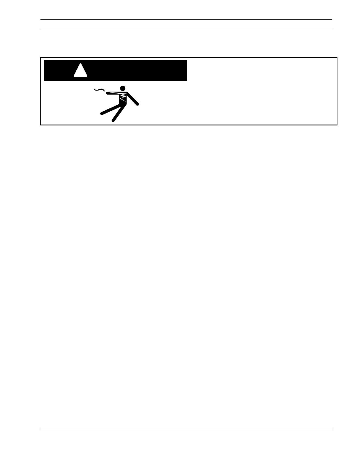
DANGER
!
Hazardous voltages. Electric shock
can kill.
· Do NOT touch plasma torch, cutting table or
cable connections during plasma cutting process.
· Always turn power off to plasma power
supplies before touching or servicing plasma torch.
· Always turn power off to plasma power
supplies before servicing any system component.
· Do not touch live electrical parts.
· Keep all panels and covers in place when
machine is connected to power source.
· Wear insulating gloves, shoes and clothing to
insulate yourself from workpiece and electrical
ground.
· Keep gloves, shoes, clothing, work area, and
equipment dry.
· Replace worn or damaged cables.
Fume hazard.
WARNING
!
Fumes and gases generated by the plasma cutting
process can be hazardous to your health.
· Do NOT breathe fumes.
· Do not operate plasma torch without fume
removal system operating properly.
· Use additional ventilation to remove fumes if
necessary.
· Use approved respirator if ventilation is not
adequate.
· Provide positive mechanical ventilation when
cutting galvanized steel, stainless steel, copper,
zinc, beryllium, or cadmium. Do not breathe these
fumes.
·
operations. Heat or arc rays can react with
chlorinated hydrocarbon vapors to form phosgene,
a highly toxic gas and other irritant gases.
Do not operate near degreasing and spraying
6

PT-20/21 AMX Plasmarc Torches
WARNING
!
Radiation hazard.
Arc rays can injure eyes and burn skin.
· Wear correct eye and body protection.
· Wear dark safety glasses or goggles with side
shields. Refer to following chart for recommended
lens shades for plasma cutting:
Arc Current Lens Shade
Up to 100 Amps Shade No. 8
100-200 Amps Shade No. 10
200-400 Amps Shade No. 12
Over 400 Amps Shade No. 14
· Replace glasses/goggles when lenses are
pitted or broken
· Warn others in area not to look directly at the
arc unless wearing appropriate safety glasses.
· Prepare cutting area to reduce reflection and
transmission of ultraviolet light.
§ Use special paint on walls to absorb UV
light.
§ Install protective screens or curtains to
reduce ultraviolet transmission.
7
PT-20/21 AMX Plasmarc Torches
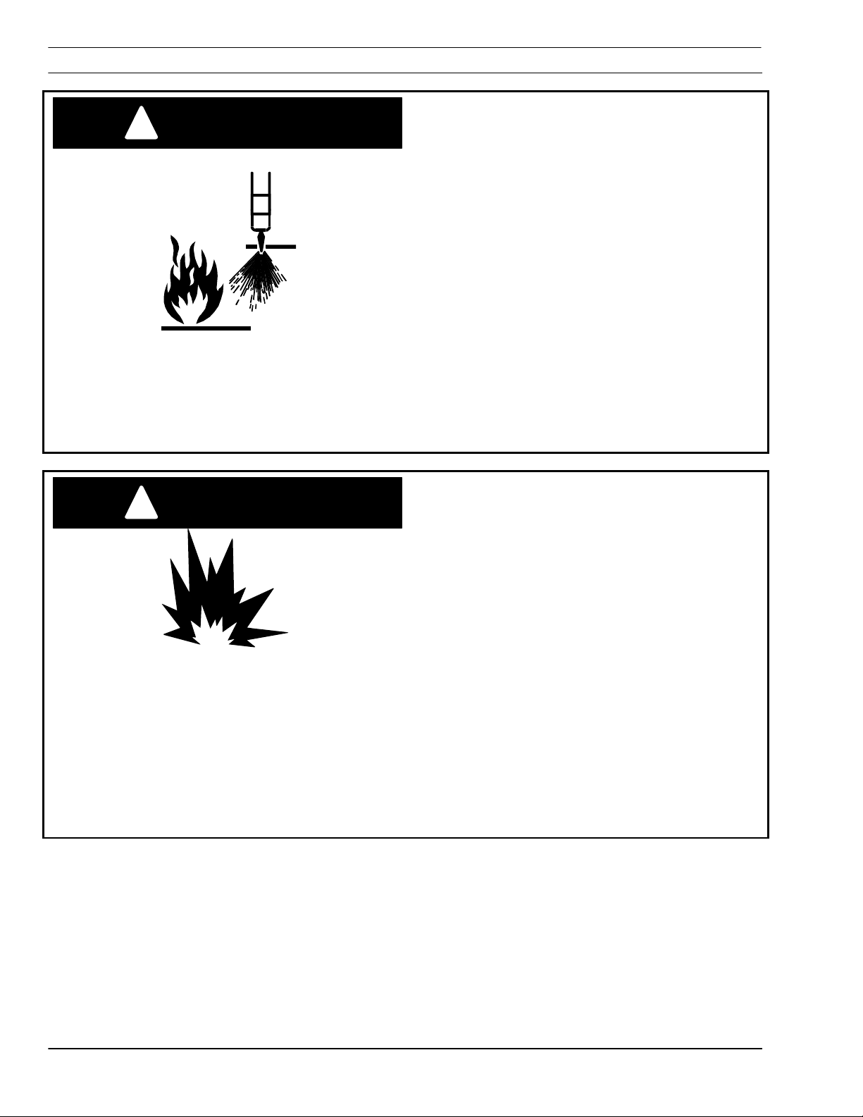
WARNING
!
Burn Hazard.
Heat, spatter, and sparks cause fire and burns.
· Do not cut near combustible material.
· Do not have on your person any combustibles
(e.g. butane lighter).
· Pilot arc can cause burns. Keep torch nozzle
away from yourself and others when activating
plasma process.
· Wear correct eye and body protection.
· Wear gauntlet gloves, safety shoes and hat.
· Wear flame-retardant clothing covering all
exposed areas.
· Wear cuffless trousers to prevent entry of
sparks and slag.
· Have fire extinguishing equipment available for
use.
Explosion hazard.
WARNING
!
· Certain molten aluminum-lithium (Al-Li) alloys
can cause explosions when plasma cut OVER
water.
§ These alloys should only be dry cut on a
dry table.
§ DO NOT dry cut over water.
§ Contact your aluminum supplier for
additional safety information regarding
hazards associated with these alloys
Do not cut in atmospheres containing
·
explosive dust or vapors.
·
Do not carry any combustibles on your person
(e.g. butane lighter)
· Do not cut containers that have held
combustibles.
.
8

PT-20/21 AMX Plasmarc Torches
Service Precautions
DANGER
!
Hazardous voltages. Electric shock
can kill.
· Do NOT touch plasma torch, cutting table or
cable connections during plasma cutting process.
· Always turn power off to plasma power
supplies before touching or servicing plasma torch.
· Always turn power off to plasma power
supplies before removing covers or panels to
service any system component.
· Do not touch live electrical parts.
· Keep all panels and covers in place when
machine is connected to power source.
· Keep gloves, shoes, clothing, work area, and
equipment dry.
· Inspect power and ground leads cables for
wear or cracking. Replace worn or damaged
cables. Do not use if damaged.
· Never bypass safety interlocks.
· Follow lock-out procedures.
Establish and adhere to preventive maintenance.
CAUTION
CAUTION
!
A composite program can be established from
recommended schedules.
Avoid leaving test equipment or hand tools on
machine. Severe electrical or mechanical damage
could occur to equipment or machine.
Extreme caution should be used when probing
circuitry with an oscilloscope or voltmeter.
Integrated circuits are susceptible to over voltage
damage. Power off before using test probes to
prevent accidental shorting of components.
All circuit boards securely seated in sockets, all
cables properly connected, all cabinets closed and
locked, all guards and covers replaced before
power is turned on.
9

PT-20/21 AMX Plasmarc Torches
Safety References -- Regulations, Standards, Guidelines
USA
The following recognized publications on safety in welding and cutting
operations are recommended. These publications have been prepared
to protect persons from injury or illness and to protect property from
damage, which could result from unsafe practices. Although some of
these publications are not related specifically to this type of industrial
cutting apparatus, the principles of safety apply equally.
· “Precautions and Safe Practices in Welding and Cutting with
Oxygen-Fuel Gas Equipment,” Form 2035. ESAB Cutting
Systems.
· “Precautions and Safe Practices for Electric Welding and Cutting,”
Form 52-529. ESAB Cutting Systems.
· “Safety in Welding and Cutting” - ANSI Z 49.1, American Welding
Society, 2501 NW 7th Street, Miami, Florida, 33125.
· “Recommended Safe Practices for Shielded Gases for Welding and
Plasma Arc Cutting” - AWS C5.10-94, American Welding Society.
· “Recommended Practices for Plasma Arc Welding” - AWS C5.1,
American Welding Society.
· “Recommended Practices for Arc Cutting” - AWS C5.2, American
Welding Society.
· “Safe Practices” - AWS SP, American Welding Society.
· “Standard for Fire Protection in Use of Cutting and Welding
Procedures” - NFPA 51B, National Fire Protection Association, 60
Batterymarch Street, Boston, Massachusetts, 02110.
· “Standard for Installation and Operation of Oxygen - Fuel Gas
Systems for Welding and Cutting” - NFPA 51, National Fire
Protection Association.
· “Safety Precautions for Oxygen, Nitrogen, Argon, Helium, Carbon
Dioxide, Hydrogen, and Acetylene,” Form 3499. ESAB Cutting
Systems. Obtainable through your ESAB representative or local
distributor.
· "Design and Installation of Oxygen Piping Systems," Form 5110.
ESAB Cutting Systems.
· “Precautions for Safe Handling of Compressed Gases in
Cylinders”, CGA Standard P-1, Compressed Gas Association.
Literature applicable to safe practices in welding and cutting with
gaseous materials is also available from the Compressed Gas
Association, Inc., 500 Fifth Ave., New York, NY 10036.
10

PT-20/21 AMX Plasmarc Torches
International
Accident Prevention
VBG 1 General Provisions
VDE Regulations
VBG 4 Electrical Equipment and operating
Equipment
VBG 15 Welding, Cutting and related working
methods
VBG 48 Shot Blasting Works
VBG 61 Gases
VBG 62 Oxygen
VBG 87 Operating liquid jet cutting machines
VBG 93 Laser beams, accident prevention and
Electro-technology
VBG 121 Noise
VDE 0100 Erection of power installations with normal
voltages up to 1000 volts
VDE0113 Electrical equipment of industrial machines
VDE 0837 Radiation safety of laser products; users
guide (DIN EN 60825)
VDE 0837-
Specification for laser guards
50
TRAC Technical Rules for Acetylene and Carbide Stores
TRAC-204 Acetylene lines
TRG Technical Rules for Pressure gases
TRAC-206 Acetylene cylinder battery systems
TRAC-207 Safety devices
TRG 100 General regulations for pressure gases
TRG 101 Pressure gases
TRG 102 Technical gas mixtures
TRG 104 Pressure gases; alterative use of
compressed gas tanks
11

PT-20/21 AMX Plasmarc Torches
DIN Standards
DIN 2310
DIN 2310
DIN 2310
DIN 2310
DIN 4844
DIN EN ISO Harmonized Standards
292/1 and 2
DIN EN 559 Hoses for welding, cutting and allied
DIN EN 560 Hose connections and hose couplings for
DIN EN 561 Gas welding equipment hose couplings
Part 1
Part 2
Part 4
Part 5
Part 1
DIN EN
Thermal cutting; terminology and
nomenclature
Thermal cutting; determination of quality of cut
faces
Thermal cutting; arc plasma cutting; process
principles, quality, dimensional tolerances
Thermal cutting; laser beam cutting of metallic
materials; process principles
Safety markings (DIN EN 7287)
Safety of machinery
processes
equipment for welding, cutting and allied
processes
VDI Guidelines
DIN EN
626-1
DIN EN
848-1
DIN EN
1829
DIN EN
9013
DIN EN
12584
DIN EN
12626
DIN EN
28206
DIN EN
31252
DIN EN
31553
DIN EN
60204-1
DIN EN
60825
DIN EN 999 Arrangement of protection devices
Safety of machines, reduction of risks to
health
Single spindle vertical milling machines
High pressure water jet machines
Thermal cutting, oxygen cutting, process
principles, dimensional tolerances
Imperfections in oxy/fuel flame cuts, laser
beam cuts and plasma
Laser processing machines
Acceptance testing for oxygen cutting
machines
Laser Equipment
Laser and laser related equipment
Electrical equipment of machines
Radiation safety of laser products
VDI 2906 Quality of cut faces on metallic workpieces;
abrasive water jet cutting and arc plasma
cutting
VDI 2084 Room air; Technical systems for welding
workshops
12

PT-20/21 AMX Plasmarc Torches
· The plasma arc cutting process employs
WARNING
!
I. Description Introduction
PT-20AMX
PT-20 AMX
Without Rack; 25 ft. 0558003426
With Rack; 25 ft. 0558003427
WARNING
!
Without Rack; 50 ft. 0558003422
With Rack; 50 ft. 0558003421
RAS; With Rack, 4 ft. 0558003424
RAS, With Rack, 17 ft. 0558003425
PT-21 AMX (for use with PowerCut 1250 and PowerCut 1500)
Without Rack; 50 ft. 0558003615
With Rack; 50 ft. 0558003614
Without Rack; 25 ft. 0558003617
With Rack; 25 ft. 0558003616
extremely high voltages. Avoid contact with
"live" parts of the torch and machine.
· The improper use of any of the gases
employed can present a safety hazard.
· Before beginning operation with the PT20AM torch, read and understand all safety
precautions covered in this instruction
manual.
This booklet covers mainly accessories,
maintenance, and parts information for the PT20AMX and PT-21AMX plasma torches. For
installation and operating instructions for your
cutting package, refer to your power source
instruction manual.
The patented PT-20AMX is a 100 amp capacity,
pilot-arc mechanized torch available in 6 different
versions. The torch uses clean, dry air as the cut
gas for cutting carbon steel, aluminum, or stainless
steel.
PT-21 AMX Torch is identical to the PT-20 AMX torch
except it is specifically designed to connect to the
PowerCut 1250 and 1500 plasma power sources.
DO NOT use oxygen with this torch!
A hazardous fire may result.
13

PT-20/21 AMX Plasmarc Torches
Dimensional Data – PT-20AMX
1.375 inches
Without Rack
7.63 inches
II. Accessories
14.5 inches
17.125 inches
With Rack
PT-20AMX Torch Spare Parts Kits - The following
three spare parts kits are available for maintaining
the PT-20AMX torch with minimum downtime.
50 Amps - 21370
70 Amps - 21369
100 Amps – 21376
PT-21 AMX torch uses the same spare parts as
the PT-20AMX.
Description
50 AMP 21370 70 AMP 21369 100 AMP 21376
Quantity
Heat Shield (70/100 A), 21326 - 2 2
Heat Shield (50 A), 21447 2 1 1
Cutting Nozzle (50 A), 21330 5 5 5
Cutting Nozzle (70 A), 21329 - 5 5
Cutting Nozzle (100 A), 21328 - - 5
Electrode, 21150 5 5 5
Electrode 50Hz, 0558001617 5** 5** 5**
Electrode Seat, 21372
1 1 1
Electrode Insulator, 21373 1 1 1
Electrode Holder Assy, 21332 1 1 1
Baffle Tube, 21374 1 1 1
Pilot Arc Adaptor, 19497 1 1 1
O-ring, 488157 5 5 5
Lubricant (1 oz.), 17672 1 1 1
Seat/Baffle Wrench, 21375 1 1 1
1/16: Hex-Key Wrench, 93750006 1 1 1
14

PT-20/21 AMX Plasmarc Torches
Torch Holder Assembly – 0558005926
Plasma Flow Measuring Kit -- 19765
Remote Hand Control Switch with 7,6m lead
For PT-20 AMX -- 680982
For PT-21 AMX -- 0558003612
Adaptor for PCM-875 and PCM-1125 -- 19500
15

PT-20/21 AMX Plasmarc Torches
III. Installing Front End Parts
WARNING
!
Seat
Make sure power switch on console is in
OFF position and primary input power is
de-energized.
1. The seat comes assembled to the front end
of the torch. IF the seat becomes damaged, the
torch body must be replaced. DO NOT attempt
to remove the seat from torch body.
Electrode Holder Assembly
Wrench
21375
Baffle Tube
2. Electrode holder assembly (21332) includes
the baffle tube (21374). If baffle tube becomes
damaged, it can be replaced by un-threading the
damaged tube out of the holder. Use small hex
end of the wrench (21375) in hex broach on the
tube. Tighten tube securely but do not overtighten.
16

PT-20/21 AMX Plasmarc Torches
3. Install the electrode insulator (21373) onto
electrode holder assembly (21332) and then thread
electrode (21150) onto the electrode holder
assembly. Assemble electrode firmly by hand. Do
not use wrenches or pliers. These three parts
combined are the electrode assembly.
21332
21373
21150
4. Install nozzle onto the electrode assembly by
inserting small shoulder on electrode insulator into
nozzle’s rear opening. Place nozzle and electrode
assembly into the heat shield as shown in page 6.
If front end of the torch is facing down as normal in
a setup, the nozzle and electrode assembly can be
stacked in the heat shield and then assembled to
the torch. Be sure to use proper heat shield and
nozzle combination as noted in page 18.
O-ring (488157)
5. Apply a thin film of lubricant (17672) to O-ring
(488157).
17672
17
PT-20/21 AMX Plasmarc Torches
6.Tighten heat shield fully to hold the parts in firm
contact with each other and to the torch head.
“Fully” means at least 3/16 inch rotation after
electrode seat contacts electrode holder.
IMPORTANT: See Maintenance section.
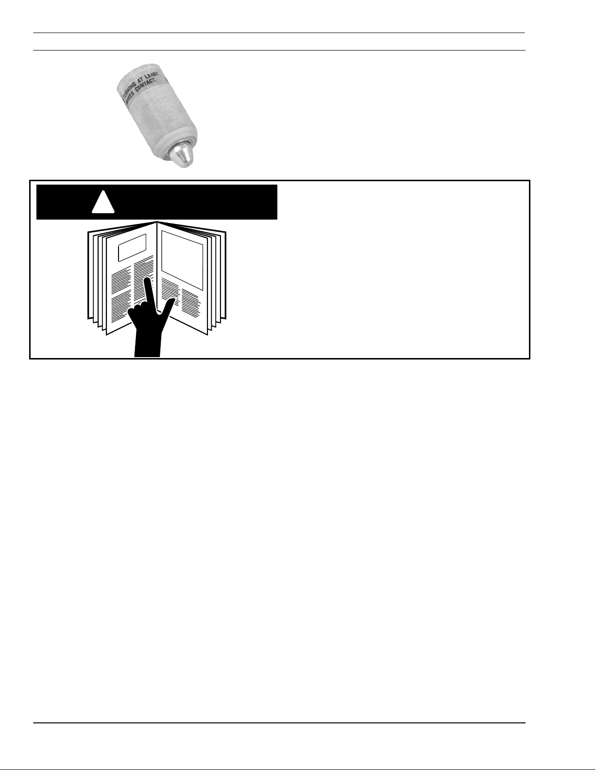
CAUTION
!
Follow all instructions in the booklet
packed with your unit. DO NOT install or
attempt to operate this torch without
following these instructions.
To connect PT-20AMX torch to the console,
connect the power cable of the torch to the
‘‘NEG’’ terminal and pilot arc cable to the ‘‘POS’’
terminal of the unit using pilot arc adaptor (19497 supplied with spare parts kit). A separate remote
control switch cable is required for connecting to
the switch receptacle on the console.
The front end of the torch contains a gas flow
check valve that acts in conjunction with the
circuitry provided in the power supply. This
patented system provides a safety interlock
preventing the torch from being accidentally
energized with high voltage when the heat shield is
removed and the torch switch is accidentally
closed.
18

PT-20/21 AMX Plasmarc Torches
2
1
4
5
3
6
7
Front End Assembly
1 Wrench Seat/Baffle 21375
2 Baffle Tube 21374
3 Electrode 21150
Electrode 50Hz 0558001617
4 Electrode Insulator 21373
5 Electrode Holder Assembly 21332
6 Heat Shield (70 and 100 Amp – Blue) 21326
Heat Shield (50 Amp – White) 21447
7 Nozzle (100 Amp) 21328
Nozzle (70 Amp) 21329
Nozzle (50 Amp) 21330
8 O-Ring 488157
8
19

PT-20/21 AMX Plasmarc Torches
Cutting Parameters for the PT-20AMX Torch
100AMP Data, Nozzle P/N 21328, Heat Shield P/N 21 326
Travel Speed
Metal
Thickness
(in.) (mm) psig bar (in.) (mm) DC volts (sec.) ipm mm/m ipm mm/m ipm mm/m
0.25 6 85 6 0.25 6 110 0,1 100 2540 105 2667 80 2032
0.50 13 85 6 0.25 6 120 0,3 45 1143 50 1270 30 762
0.75 19 85 6 0.25 6 125 1,0 27 686 35 889 15 381
1.00 25 85 6 0.25 6 130 2,75 15 381 20 508 10 254
1.25 32 85 6 0.32 8 140 NR 10 254 13 330 7 178
1.50 38 85 6 0.32 8 145 NR 7 178 10 254 5 127
Metal
Thickness
(in.) (mm) psig bar (in.) (mm) DC volts (sec.) ipm mm/m ipm mm/m ipm mm/m
0.13 3 75 5 0.19 5 105 0,1 190 4826 180 4572 80 2032
0.25 6 75 5 0.19 5 110 0,2 80 2032 85 2159 55 1397
0.50 13 85 6 0.25 6 115 0,6 30 762 30 762 20 508
0.75 19 85 6 0.25 6 130 2,3 15 381 25 635 8 203
1.00 25 85 6 0.32 8 140 NR 7 178 12 305 6 152
1.25 32 85 6 0.32 8 155 NR 5 127 10 254 3 76
Metal
Thickness
(in.) (mm) psig bar (in.) (mm) DC volts Amps ipm mm/m ipm mm/m ipm mm/m
0.06 2 75 5 0.13 3 110 40 150 3810 150 3810 130 3302
0.13 3 75 5 0.13 3 110 40 100 2540 105 2667 75 1905
0.19 5 85 6 0.13 3 110 50 100 2540 90 2286 50 1270
0.25 6 85 6 0.19 5 120 50 65 1651 75 1905 30 762
0.38 10 85 6 0.25 6 130 50 40 1016 30 762 8 203
0.50 13 85 6 0.32 8 150 50 18 457 8 203 6 152
“NR” indicates piercing is not recommended
Air
Pressure
Air
Pressure
Air
Pressure
Stand-Off Arc
Voltage
70AMP Data, Nozzle P/N 21329, Heat Shield P/N 21326
Stand-Off Arc
Voltage
50AMP Data, Nozzle P/N 21330, Heat Shield P/N 21447
Stand-Off Arc
Voltage
Pierce
Time
Pierce
Time
Arc
Current
Mild Steel Aluminum Stainless
Mild Steel Aluminum Stainless
Mild Steel Aluminum Stainless
20
PT-20/21 AMX Plasmarc Torches
IV. Maintenance
WARNING
!
A. General
Before any maintenance is attempted on
this torch, make sure the POWER SWITCH
on the console is in the OFF position and
the PRIMARY INPUT POWER is
DEENERGIZED.
1. The gas flow check valve is part of the safety
interlock and is permanently assembled in the
torch head. The head must be replaced if this valve
malfunctions.
2. Periodically check heat shield, electrode holder
assembly, electrode nozzle seat, and electrode
insulator. Replace if worn or damaged.
3. Apply a thin film of lubricant 17672 (supplied in
spare parts kit) to O-ring. Check O-ring for damage
whenever shield is removed. Replace if necessary.
4. Power and pilot arc cables should be inspected
periodically. If cuts through protective sheath or if
gas leaks are noted, replace damaged component.
21

PT-20/21 AMX Plasmarc Torches
B. Dirt or Contamination
Dirt or other contamination in the torch and loose
consumable parts can cause premature failure of
the PT-20AM Torch through internal arcing. To
avoid this, users are instructed to do the following:
1. Ensure that clean, dry, or oil-free air is being
used.
2. Avoid excessive use of the silicone o-ring
grease used to lubricate the torch o-ring. A thin
film is sufficient.
3. Wipe the torch body insulator clean with a
cloth before installing each fresh set of
consumables. The ability of the insulator to resist
arc tracking over its surface is reduced when dirt
or other contamination is allowed to collect there.
C. Loose Consumables
Tests have shown that with proper use of the torch
within rated operating conditions (especially arc
current and gas flow rate), the torch consumable
parts do not become loose if they are firmly
installed in the first place.
1. Tighten heat shield fully at each consumable
change or inspection. “Fully” means at least 5
mm of rotation after electrode seat contacts
electrode holder.
2. Check consumable tightness at beginning of
each work shift, even if everything was working
normally at the end of the previous shift.
3. Ensure that the torch electrode seat and
electrode holder are clean and free of dust or dirt
Debris may prevent mating surfaces from having
solid contact.
22
PT-20/21 AMX Plasmarc Torches
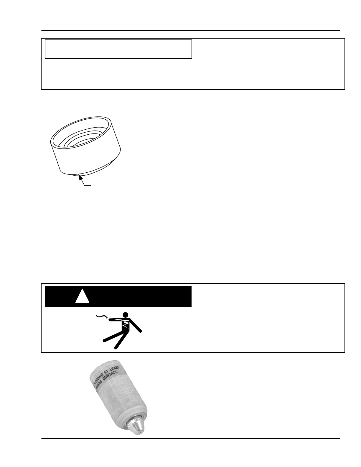
The torch requires good electrical contact
CAUTION
D. Damage Caused by Loose Parts and Torch Overheating.
between the electrode seat and electrode
holder. If good contact is not maintained,
then the resulting potential difference
causes internal arcing and possible torch
damage.
Electrode Insulator (21373)
Deformation at this edge indicates
torch overheating. Check gas
pressure, gas flowrate and current
setting. Deformation leads to loose
parts and internal arcing. Do not
operate torch with a deformed
insulator.
E. Consumables- Remove and Replace
1. Bring torch to a position where it is easily
Arc tracking indicates loose parts. Make sure heat
shield is tightened fully, at least 5mm of rotation
after electrode seat contacts electrode holder.
Check tightness again after a few minutes of use.
Parts damaged by arcing will cause destruction of
torch. Parts damaged by arcing must be replaced.
accessed by machine operator, in its normal
vertical position and at least 6 inches above the
workpiece or the edge of the water table.
Make sure that the power source has been
WARNING
!
turned off and that the power cable has
been unplugged at the wall receptacle
before proceeding.
2. Unscrew the heat shield and lower it away
from the torch, allowing nozzle and electrode
assembly to remain with shield.
23

PT-20/21 AMX Plasmarc Torches
3. Remove the nozzle and electrode assembly
from the shield and inspect for wear. The nozzle
orifice should be round at both the entrance and
the exit. If the nozzle orifice is worn in an oval
shape or shows other signs of damage at either
end, it should be replaced. The inside of the nozzle
may have light gray deposits from the electrode.
These may be removed with steel wool but care
must be taken to remove all traces of the steel
wool afterward.
1,5 mm
If the electrode has a pit which is more than
1.5mm deep at its center, replace it. This is done
by unscrewing the electrode from the electrode
holder. Grasp the electrode holder with the fingers
using the two flats and grasp the electrode
between the thumb and finger of the other hand
and twist.
Inspect electrode insulator and electrode holder
assembly for signs of damage such as arc tracking
or cracking and replace them if any are found.
Insure that the baffle tube is securely threaded into
the electrode holder, but do not overtighten. Use
the small hex end of the plastic wrench in the
spare parts kit.
After installing the electrode insulator onto the
electrode holder assembly, install electrode by
reversing the procedure used to remove it. Note
that firm tightening of the electrode by hand is
sufficient, the use of tools such as wrenches or
pliers is not required or recommended.
4. Inspect heat shield for signs of damage or
wear. The gas holes inside shield should not be
blocked by debris, and there should be no signs of
arcing anywhere inside the shield. The outer
insulating jacket of the shield should not be
severely charred or eroded. Replace the heat
shield if any of the above damage is found.
.
24
PT-20/21 AMX Plasmarc Torches
Inspect o-ring of torch
6. Install the nozzle and the electrode assembly
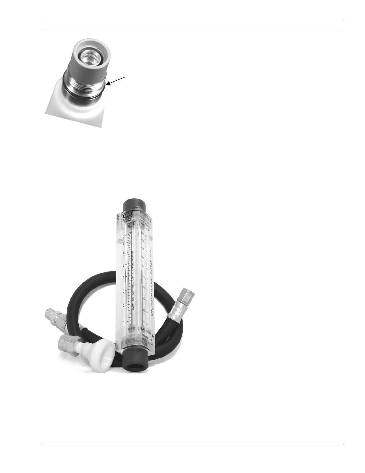
F. Measuring Torch Gas Flows
5. Inspect the o-ring on the torch. If it shows
signs of wear or damage, replace it. If it is dry,
lubricate it with a thin film of lubricant supplied with
spare parts kit
into heat shield and thread heat shield onto torch.
The shield should be tightened fully to insure good
electrical contact for electrode and nozzle. "Fully"
means at least 3/16 inch of rotation after electrode
seat contacts electrode holder.
If low gas flow is suspected of causing poor cutting
performance or short consumable life, the flow can
be checked by using Plasma Torch Flow
Measuring Kit (19765). The kit includes a hand
held rotameter (flowmeter) which will indicate the
gas flow rate exiting the torch. The kit also includes
a set of instructions which should be followed
exactly to insure safe and accurate use of the
rotameter.
Total air flow rate in the PT-20AMX should be
325cfh minimum with any nozzle at 75 psi.
Flow Measuring Kit -- P/N 19765
25

PT-20/21 AMX Plasmarc Torches
G. Removal and Replacement of the Torch Body
Make sure that the power source has been
WARNING
!
turned off and that the power cable has
been unplugged at the wall receptacle
before proceeding.
PT-20AMX Torch
1. Cut and remove the shrink wrap at the back
end of the torch handle. Unscrew the handle from
the torch body and slide it back onto the torch
cable assembly in order to expose the torch
connections.
2. Remove the electrical tape which secures the
short piece of vinyl tubing on the pilot arc cable.
Slide the tubing away from the torch and onto the
pilot arc cable to expose the pilot arc connector.
3. Use the 1/16" Allen Wrench supplied in the
spare parts kit to loosen the pilot arc connector set
screw closest to the torch body, being careful not
to totally remove the screw. Slip the torch’s pilot arc
lead out of the connector.
4. Unscrew the power cable fitting from the
torch’s power lead using a 7/16" open-end wrench
and remove the torch body.
5. Connect the pilot arc cable and the power
cable to the new torch body’s pilot arc lead and
power lead by reversing the steps taken to
disconnect them. Tighten the pilot arc connector
set screw fitting firmly but do not overtighten.
Torque the power fitting to 20 lb. in..
26
6. Slide the vinyl tubing forward to cover the pilot
arc connector and secure in place with electrical
tape.
7. Slide the handle forward and thread it firmly
onto the torch body.
8. Slide the new piece of shrink tube over the
torch handle and shrink in place over the handle’s
end and the cable sheath.
PT-20/21 AMX Plasmarc Torches
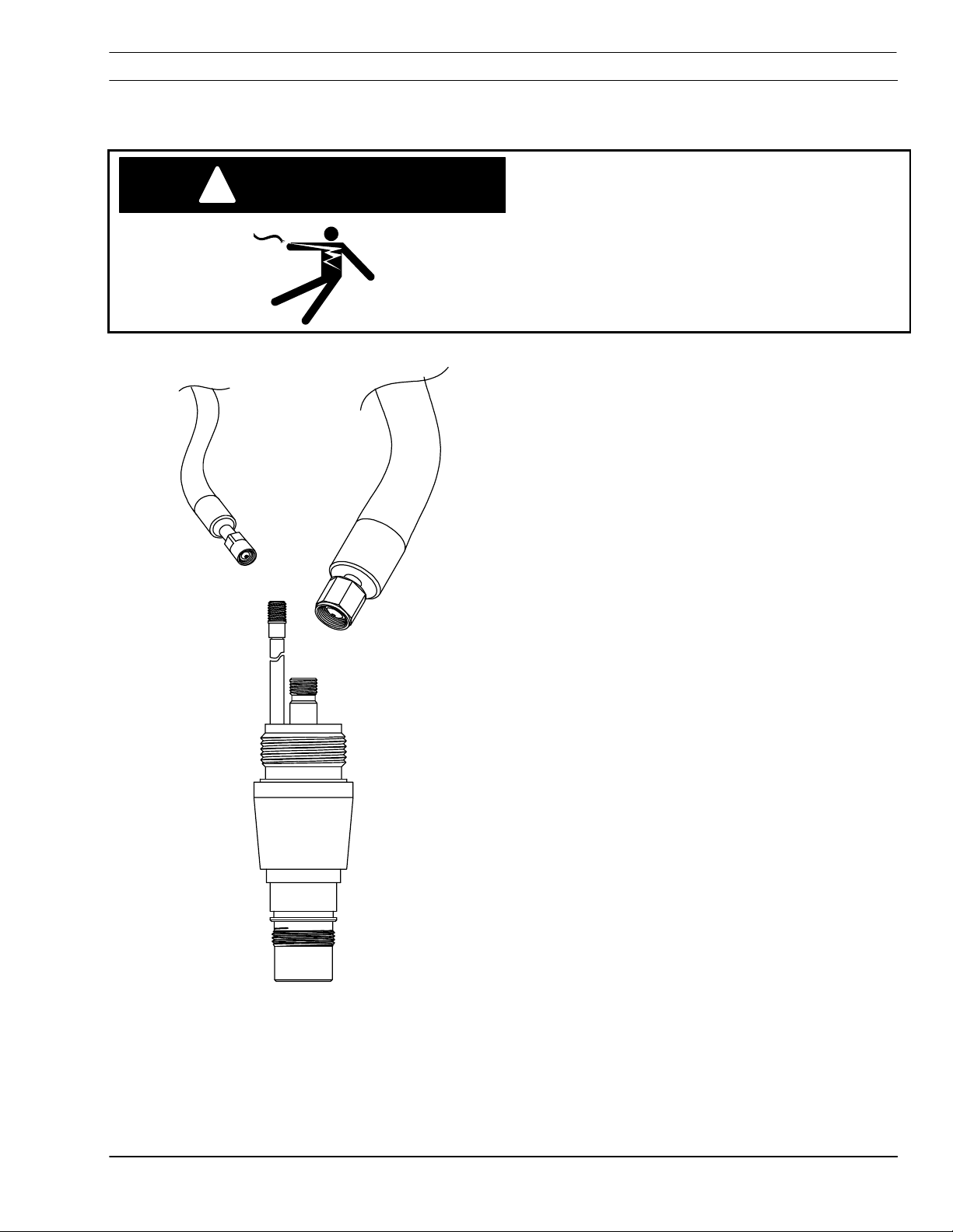
PT-21AMX Torch body Removal and Replacement
Make sure that the power source has been
WARNING
!
turned off and that the power cable has
been unplugged at the wall receptacle
before proceeding.
1. Remove shrink wrap or electrical tape from lead
2. Remove lock ring and slide up on torch lead.
3. Holding torch body steady, unscrew handle
end of torch handle (if any).
from torch body and slide back onto the
braided shield cable assembly to expose torch
connections.
4. Unscrew the power cable fitting from the torch
power lead connector using a 7/16” open end
wrench.
5. Unscrew Pilot arc connector using a ¼”
wrench.
6. Remove torch body and reverse procedure.
Note: Tighten handle on torch body hand tight.
Note: Tighten lock ring on handle with pliers.
27

PT-20/21 AMX Plasmarc Torches
H. Removal and Replacement of the Torch Cables
Make sure that the power source has been
WARNING
!
turned off and that the power cable has
been unplugged at the wall receptacle
before proceeding.
ESAB Welding &
PT-20AMX
1. Disconnect the torch cable assembly from the
power source. Refer to your power source
instruction booklet for detailed instructions.
2. Remove the torch body and handle from the
cable assembly as described in the previous
section.
3. Lay the cable assembly on the floor and
stretch it out completely. This should be done in an
area that is approximately 1-1/2 times as long as
the cable assembly.
4. Using a piece of cord or sturdy twine about
1/2 the length of the torch cables, secure one end
of the cord around the cables at the torch end and
secure the other end of the cord to a stationary
object.
5. Remove the tape securing the cable sheath
to the cables at both ends.
6. Secure the torch cables at the power source
end and pull the sheath completely off the cables
and onto the cord used in step 4.
28
7. Untie the cord from the cables and replace
the damaged cable or cables. Be sure to retain the
vinyl tube used to insulate the pilot arc connector.

PT-20/21 AMX Plasmarc Torches
8. Resecure the torch ends of the cables with
the cord, and pull the cable sheath back off of the
cord and onto the cables.
9. Untie the cord from the cables and
temporarily secure the torch body to the cable
connections.
10. Secure the sheath to the cables using
electrical tape at both ends.
11. Remove the torch body (temporarily installed
in step 9) from the cables and slide the handle over
the cables and cable sheath. Install the vinyl tube
over the pilot arc cable.
12. Reconnect the torch body to the cables as
described in the previous section and reinstall the
torch handle onto the torch body.
13. Reconnect the torch cables to the power
source.
29

PT-20/21 AMX Plasmarc Torches
V. Replacement Parts – PT-20AMX Torches 4ft. – 17 ft. – 25 ft.
(0558003424, 0558003425, 0558003426, 0558003427)
1
4
5
10
6
1
7
8
9
15
30
11
13
12
14

PT-20/21 AMX Plasmarc Torches
.
PT-20 AMX Plasma Torch with Coaxial Pilot Arc Cable
With 4 ft. torch leads, without handle rack P/N 0558003424
With 17 ft. torch leads, without handle rack P/N 0558003425
With 25 ft. torch leads, without handle rack P/N 0558003426
With 25 ft. torch leads, with handle rack P/N 0558003427
Ref. Description...................................................................................................
1 Torch Lead Assembly – 4 ft. ...............................................................
Torch Lead Assembly – 17 ft. .............................................................
Torch Lead Assembly – 25 ft. .............................................................
4 Lock Ring .......................................................................................... 57N70
5 Rubber Boot ...................................................................................... 0558001157
6 Wrap with electrical tape as shown.............................................................. Reference
7 H.F. Connector .................................................................................. 17974
8 Set screw 6-32 X 3/16 ................................................................................Reference
9 Insulate with vinyl tubing and secure with electrical tape............................... Reference
Handle and sleeve without rack .......................................................... 22329
10
Handle and sleeve with rack............................................................... 0558003419
Part Number
0558002638
0558002639
0558003383
11 Handle........................................................................................................Reference
12 Basic Torch Body Assembly............................................................... 21359
13 O-ring supplied with torch body.......................................................... 5W92
14 O-ring supplied with torch body.......................................................... 488157
15 Shield Shroud – 25 ft.......................................................................... 72020003
16 Lubricant ........................................................................................... 17672
31

PT-20/21 AMX Plasmarc Torches
PT-20 AMX Plasmarc Torches 50 ft. (0558003422, 0558003421)
15
16
5
4
6
ESAB Welding &
PT-20AMX
9
8
7
3
1
2
10
11
13
12
14
32

PT-20/21 AMX Plasmarc Torches
.
PT-20 AMX Plasma Torch -- wire mesh shielded
With 50 ft. torch leads, without handle rack P/N 0558003422
With 50 ft. torch leads, with handle rack P/N 0558003421
Ref. Description...................................................................................................
1 Pilot Arc Cable Assy. – 50 ft. ............................................................. 948163
2 .875-14 L.H. ...............................................................................................Reference
3 Power Cable Assembly – 50 ft............................................................ 20621
4 Lock Ring .......................................................................................... 57N70
5 Sheath – 50 ft. ................................................................................... 995829
6 Wrap with electrical tape as shown.............................................................. Reference
7 H.F. Connector .................................................................................. 17974
8 Set screw 6-32 X 3/16 ................................................................................Reference
9 Insulate with vinyl tubing and secure with electrical tape............................... Reference
Handle and sleeve without rack .......................................................... 22329
10
Handle and sleeve with rack............................................................... 0558003419
Part Number
11 Handle........................................................................................................Reference
12 Basic Torch Body Assembly............................................................... 21359
13 O-ring supplied with torch body.......................................................... 5W92
14 O-ring supplied with torch body.......................................................... 488157
15 Shield Shroud – 25 ft.......................................................................... 72020003
16 Lubricant ........................................................................................... 17672
33

PT-20/21 AMX Plasmarc Torches
PT-21 AMX Plasmarc Torches 25 ft.and 50 ft.(0558003614, 0558003615, 0558003616, 0558003617)
4
5
6
8
14
15
9
6
10
1
3
7
12
11
2
13
34

PT-20/21 AMX Plasmarc Torches
.
PT-21 AMX Torch Used with PowerCut 1250 and PowerCut 1500 Power Sources
With 25 ft. m torch leads, without handle rack P/N 0558003617
With 25 ft torch leads, with handle rack P/N 0558003616
With 50 ft. torch leads, without handle rack P/N 0558003615
With 50 ft. torch leads, with handle rack P/N 0558003614
Ref. Description...................................................................................................
Pilot Arc Cable Assy. – 25 ft. ............................................................. 0558003609
1
Pilot Arc Cable Assy. – 50 ft. ............................................................. 0558003610
2 0,375 – 14 L.H. A/I-G.................................................................................. Reference
Power Cable Assembly – 25 ft............................................................ 0558003606
3
Power Cable Assembly – 50 ft............................................................ 0558003607
4 Lock Ring .......................................................................................... 57N70
5 Sheath – 25 ft./ 50 ft. ......................................................................... 72020003
6 Wrap with electrical tape as shown.............................................................. Reference
7 Shield Ground............................................................................................. Reference
8 Handle........................................................................................................Reference
Part Number
9 Insulate with vinyl tubing and secure with electrical tape............................... Reference
Handle and sleeve without rack .......................................................... 22329
10
Handle and sleeve with rack............................................................... 0558003419
11 Basic Torch Assembly – PT-21........................................................... 0558003611
12 O-ring supplied with torch body.......................................................... 5W92
13 O-ring supplied with torch body.......................................................... 488157
Shield Shroud – 25 ft.......................................................................... 995832
14
Shield Shroud – 50 ft.......................................................................... 995826
15 Lubricant ........................................................................................... 17672
35

Customer // Technical Support
(843) 664-4405
(800) ESAB-123 (372-2123)
ESAB Welding and Cutting Products
PO BOX 100545 Ebenezer Road
Florence, SC 29501-0545
http://www.esab.com
ESAB Cutting Systems – Canada
6010 Tomken Road
Mississauga, Ontario Canada L5T 1X9
Phone: (905) 670-0220
Fax: (905) 670-4879
ESAB-Hancock GmbH
Cutting Technologies
P.O Box 1128
D-61174 Karben
Robert-Bosch-Strasse 20
D-61184 Karben
Phone + 49 60 39 40-0
Fax + 49 60 39 40 301_302
http://www.esab.com
esab_info@compuserve.com
Printed in U.S.A
 Loading...