

OPERATING INSTRUCTIONS for
®
October, 2000
R-522
CYLINDER REGULATORS
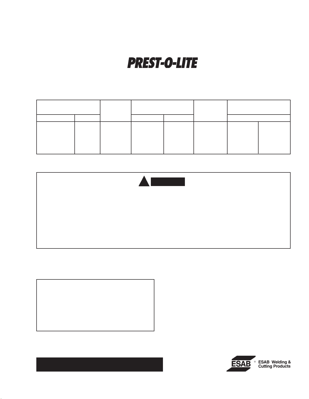
Rated Max.
Regulator Gas Connection,CGA No Delivery Pressure Gauges, PSIG
Model P/N Service Inlet Outlet Press. PSIG Cylinder Delivery
R-522-75-540 22237 Oxygen 540 022 75 4000 100
R-522-15-510 22241 Acetylene 510 023 15 400 30
R-522-15-520 22238 Acetylene 520(B) 023 15 400 30
R-522-15-200 22239 Acetylene 200(MC) 023 15 400 30
R-522-15-200 22240 Acetylene 300 023 15 400 30
• CGA-022 (formerly "B" oxygen) - 9/16"- 18 RH male conn.
CGA-023 (formerly "B" Acet.) - 9/16"-18 LH male conn.
•
F-15-454
CAUTION
!
These INSTRUCTIONS are for experienced operators. If you are not fully familiar with the principles of operation and safe
practices for oxy-fuel gas equipment, we urge you to read our booklet "Precautions and Safe Practices for Gas Welding,
Cutting and Heating," Form 2035. Do NOT permit untrained persons to install, operate, or maintain this equipment. Do NOT
attempt to install or operate this equipment until you have read and fully understand these Instructions. If you do not fully
understand these Instructions, contact your supplier for further information.
The regulators covered by these Instructions are listed by Underwriter's Laboratories only when using parts manufactured
by ESAB Welding & Cutting Products to the specifications on file with Underwriter's Laboratories, Inc., and when they are
used in the gas service for which they are designed and listed. The use of other parts that cause damage or failure to the
equipment will void the manufacturer's warranty.
IMPORT ANT : For packing purposes, the pressureadjusting screw of the regulator may be either
turned in or packed separately . If installed in regulator, back out screw (turn counterclockwise) until
it turns freely . If packed separately , install the screw
in the regulator cap and turn it in (clockwise) only
one or two turns.
For Safety Precautions, Installation & Operating
Instructions, see other side.
Be sure this information reaches the operator.
You can get extra copies through your supplier.

Safety Precautions
! !
n OXYGEN causes many metals and other materials
to burn violently .
n INERT GAS OR CARBON DIOXIDE can cause suf-
focation in confined spaces.
n FUEL GAS can explode in air or oxygen.
l Keep regulator clean and in good repair. Do NOT
oil or grease regulator. Grease and oil on regulator or valve parts can cause regulator fires.
l Always work in a well-ventilated area.
l Prevent leaks and keep away from heat, flame,
and sparks.
l Do not change CGA inlet connection from number
stamped on regulator body .
l Follow Operating Instructions on this sheet.
l This regulator must be installed, operated and
maintained only by trained servicemen.
l For complete safety information on welding equip-
ment, read Form 2035 (oxy-fuel gas) and 52-529
(arc welding). For safety information on gases,
see your supplier.
n DO NOT remove internal part from inlet connection
or R-522-75-540 Oxygen Model.
TO CONNECT:
1.Open the cylinder or station valve slightly, for an instant (this is termed 'cracking the valve'). This will
blow out dust or dirt that may have collected in the
valve outlet. Be sure to keep your face away from
the valve outlet to protect your eyes from dust or dirt.
Never crack a fuel gas valve near sparks, flames,
or another possible source of ignition.
2.Make sure the regulator pressure-adjusting screw is
released by turning it counterclockwise until it turns
freely .
3.Attach the regulator to the valve and tighten the connection nut with a wrench.
4.Open the cylinder valve slowly. (Open acetylene
cylinder valves no more than 1-1/2 turns.) Never
stand in front of or behind the regulator when
opening the valve. Always stand to one side.
5.Attach the hose to the regulator outlet and to the
equipment with which it is to be used.
TO ADJUST PRESSURE:
1.To increase delivery pressure, turn the pressureadjusting screw clockwise. To decrease delivery
pressure, turn the pressure-adjusting screw counterclockwise.
2.When making the initial delivery pressure adjustment,
all valves downstream of the regulator must be open
or you will not get a true working-pressure reading
on the delivery-pressure gauge.
IMPORTANT: Before starting operations, test all con-
nections with a leak T est Solution that is
suitable for oxygen service, such as
P/N 998771 (8oz. container). Correct
any leaks before starting work. Testing
should be performed after torch or other
gas-using device has been properly connected and with maximum delivery pressure in the delivery line.
TO RELEASE PRESSURE:
If operations are to be stopped for a half-hour or more,
you should release all pressures from regulator. T o do
this, proceed as follows:
1.Close the cylinder valve.
2.Open all valves downstream of the regulator.
3.Wait until the pressure has dropped to zero, then
turn the pressure-adjusting screw counterclockwise
until it turns freely .
NOTE: If a regulator is to be out of use for a few days
or more, turn in the pressure-adjusting screw
enough to move the valve stem off its seat.
When the regulator is returned to use, be sure
to back off the pressure-adjusting screw until it
turns freely before pressure is admitted to the
regulator.
REPAIR SERVICE:
Regulators in need of repair should be returned to your
distributor, or to ESAB Welding & Cutting Products,
Remanufacturing Center, 411 S. Ebenezer Road, Florence, SC 29501.
If you have your own properly-equipped and staffed
repair facility , repair parts information for this regulator
is available on request to your distributor. Request
Form 15-455, which covers the regulators listed on this
sheet.
NOTE: Safety release device equipped on oxygen and
inert gas regulators is designed for regulator
protection; not for hose or equipment downstream. If gas escapes through the safety release device, immediately close cylinder valve,
and then remove regulator from service for repair.
F-15-454 10/2000 Printed in U.S.A.
 Loading...