

Page 1
GB
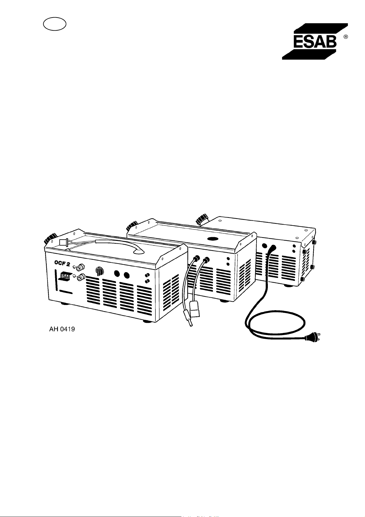
OCF 2
Instruction manual
Valid for serial no. 803 xxx--xxxx0457 680 001 GB 050819
Page 2

1 DIRECTIVE 3........................................................
2SAFETY 3...........................................................
3 INTRODUCTION 4...................................................
3.1 Equipment 4................................................................
4 TECHNICAL DATA 4.................................................
5 INSTALLATION 5....................................................
5.1 Unpacking and siting 5.......................................................
6 OPERATION 9.......................................................
6.1 Flow monitor 9..............................................................
7 MAINTENANCE 10....................................................
7.1 Inspection and cleaning 10....................................................
8 TROUBLESHOOTING 10..............................................
9 ORDERING SPARE PARTS 10..........................................
DIAGRAM 11............................................................
ORDERING NUMBER 12.................................................
Rights reserved to alter specifications without notice.
TOCe
-- 2 --
Page 3
GB
1DIRECTIVE
DECLARATION OF CONFORMITY
Esab Welding Equipment AB, 695 81 Laxå, Sweden, declares that cooling unit OCF
2 from serial number 803 onwards, conforms to standard EN 60204--1, in accordance with the requirements of directive (73/23/EEC) and appendix (93/68/EEC) and
standard EN 50199 in accordance with the requirements of directive (89/336/EEC)
and appendix ( 93/68/EEC).
-- -- -- -- -- -- -- -- -- -- -- -- -- -- -- -- -- -- -- -- -- -- -- -- -- -- -- -- -- -- -- -- -- -- -- -- -- -- -- -- -- -- -- -- -- -- -- -- -- -- -- -- -- -- -- -- -- -- -- -- -- -- -- -------Laxå 98--01--09
Paul Karlsson
Managing Director
Esab Welding Equipment AB
695 81 LAXÅ
SWEDEN Tel: + 46 584 81000 Fax: + 46 584 12336
2SAFETY
WARNING
ARC WELDING AND CUTTING CAN BE INJURIOUS TO YOURSELF AND OTHERS. TAKE PRECAUTIONS WHEN WELDING. ASK FOR YOUR EMPLOYER’S SAFETY PRACTICES WHICH SHOULD BE
BASED ON MANUFACTURERS’ HAZARD DATA.
ELECTRIC SHOCK -- Can kill
S Install and earth the welding unit in accordance with applicable standards.
S Do not touch live electrical parts or electrodes with bare skin, wet gloves or wet clothing.
S Insulate yourself from earth and the workpiece.
S Ensure your working stance is safe.
FUMES AND GASES -- Can be dangerous to health
S Keep your head out of the fumes.
S Use ventilation, extraction at the arc, or both, to take fumes and gases away from your breathing zone
and the general area.
ARC RAYS -- Can injure eyes and burn skin.
S Protect your eyes and body. Use the correct welding screen and filter lens and wear protective
clothing.
S Protect bystanders with suitable screens or curtains.
FIRE HAZARD
S Sparks (spatter) can cause fire. Make sure therefore that there are no inflammable materials nearby.
NOISE -- Excessive noise can damage hearing
S Protect your ears. Use earmuffs or other hearing protection.
S Warn bystanders of the risk.
MALFUNCTION -- Call for expert assistance in the event of malfunction.
READ AND UNDERSTAND THE INSTRUCTION MANUAL BEFORE INSTALLING OR OPERATING.
PROTECT YOURSELF AND OTHERS!
bk02d13e
-- 3 --
Page 4
GB
3 INTRODUCTION
The OCF 2 cooling unit comes in four versions, designed for use with LTN/LTR
160/200/255, DTE 200/255, LTS160/250, and semi-- automated power sources.
3.1 Equipment
Check the coolant level before use.
If necessary, top up with water and glycol.
S OCF 2L and OCF 2D are equipped with a transformer which is fed by the
welding power source.
Can be supplied with a flow monitor (0467 118 001).
S OCF 2M has relays to allow supply via the welding power source.
S OCF 2A is fitted with an earthed plug complying with Swedish regulations.
Can be stood on edge if it is fitted with feet (4 off. 0467 695 001).
4 TECHNICAL DATA
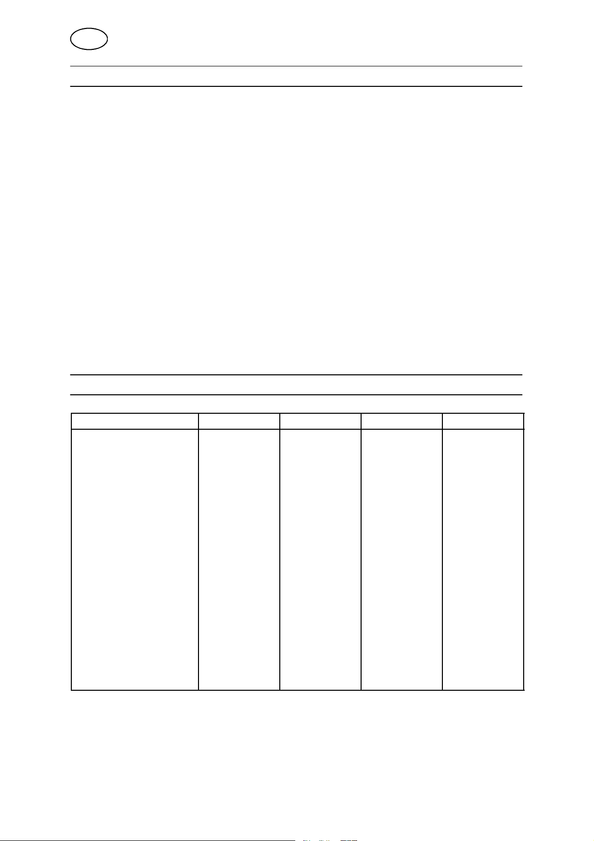
Model OCF 2L OCF 2D*) OCF 2M OCF 2A
Voltage 400 V 400 V 230 V 230 V
Power consumption 250 W 250 W 250 W 250 W
Cooling effect 2000 W 2000 W 2000 W 2000 W
Power source LTN/LTR
200,255
Drive Internal from
welding power
source
Coolant Water/Glycol Water/Glycol Water/Glycol Water/Glycol
Coolant capacity 5L 5L 5L 5L
Max. pressure 3 bar 3 bar 3 bar 3 bar
Max. water flow 4l/min 4l/min 4l/min 4l/min
Air flow 200 m3/h 200 m3/h 200 m3/h 200 m3/h
Fuse, slow 1.6 A 1.6 A
Enclosure class IP 23 IP 23 IP 23 IP 23
Weight 22 kg 25 kg 19,5 kg 19,5 kg
Dimensions 470x260x190 500x290x190 470x260x190 470x260x190
DTE 200/255 LTS 160/250 L TN/LTR 160,
Automated.
Internal from
welding power
source
Internal from
welding power
source
Internal from
power supply
*) OCF 2D is a special version with larger external dimensions, but otherwise the same as OCF 2L.
Enclosure class
The IP code indicates the enclosure class, i. e. the degree of protection against penetration by solid
objects or water. Equipment marked IP23 is designed for indoor and outdoor use.
bk02d13e
-- 4 --
Page 5
GB
5 INSTALLATION
WARNING!
This product is intended for industrial use. In a domestic environment this product may cause radio
interference. It is the user’s responsibility to take adequate precautions.
S OCF 2L/OCF 2D To be installed by an electrician.
S OCF 2M/OCF 2A Maybeinstalledbyuser.
The only tool that is required for installation is a cross--head screwdriver.
5.1 Unpacking and siting
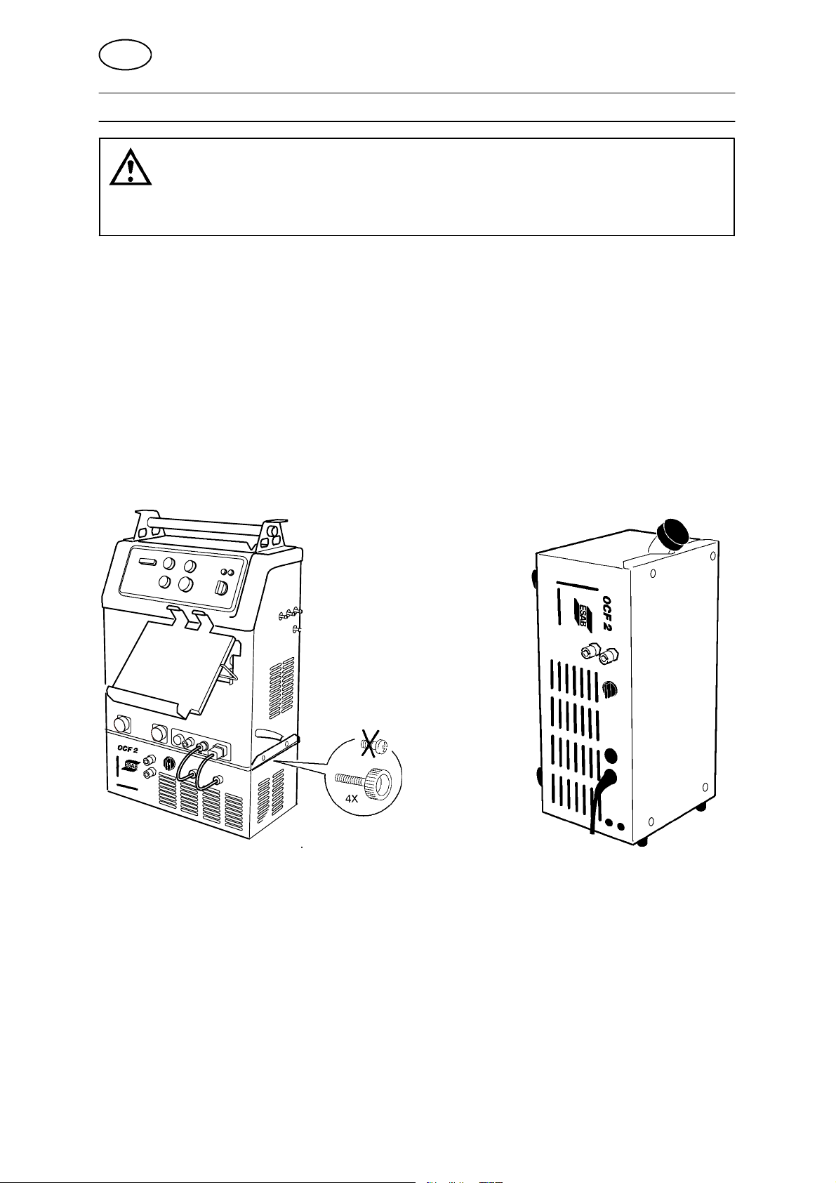
OCF 2 with a LTS 160/250 on top, with another free--standing, upright.
bk02d13e
-- 5 --
Page 6
GB
5.1.1 Connection
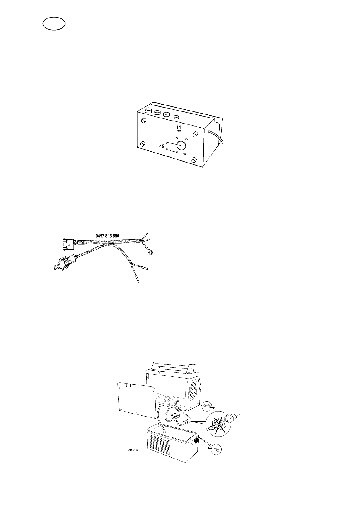
OCF 2L to LTN/LTR 200,255, NOT FITTED with connecting cable for cooling unit.
1. Unplug if necessary.
2. Remove the lower screws from the sides of the power source.
3. Remove the rear panel from the power source.
4. Hole D=38 to be drilled in base plate, see fig.1.
fig.1
5. NOTE! Clean any metal swarf from the weldin g power source.
6. Remove the front panel from the welding power source.
7. Connect the connecting cable for the cooling unit to the welding power source,
see fig.2.
066--to X02 (5--pin connector) according to drawing for relevant machine.
067--to X02 (5--pin connector) according to drawing for relevant machine
905--to earth terminal according to drawing for relevant machine
LTR 200/255
B4--to cable B4 from circuit board AP01 acc. to drawing for relevant machine
LTN 200/255
B4--to K2 on circuit board AP01 according to drawing for relevant machine
057--to ST01 thermal cut-- out according to drawing for relevant machine
065
XS24
B4
057
XS25
fig.2
8. Place the power source on the cooling unit and raise the rear edge.
9. Feed the connectors from the cooling unit through the hole in the bottom panel.
10. Remove the clamp from the terminal inside the power source and join the
connectors see fig.3.
11. Refit the rear panel.
12. Tighten the screws in the bottom through the cover on the cooling unit.
13. Connect the water--cooled torch and do a test run.
bk02d13e
fig.3
-- 6 --
Page 7
GB
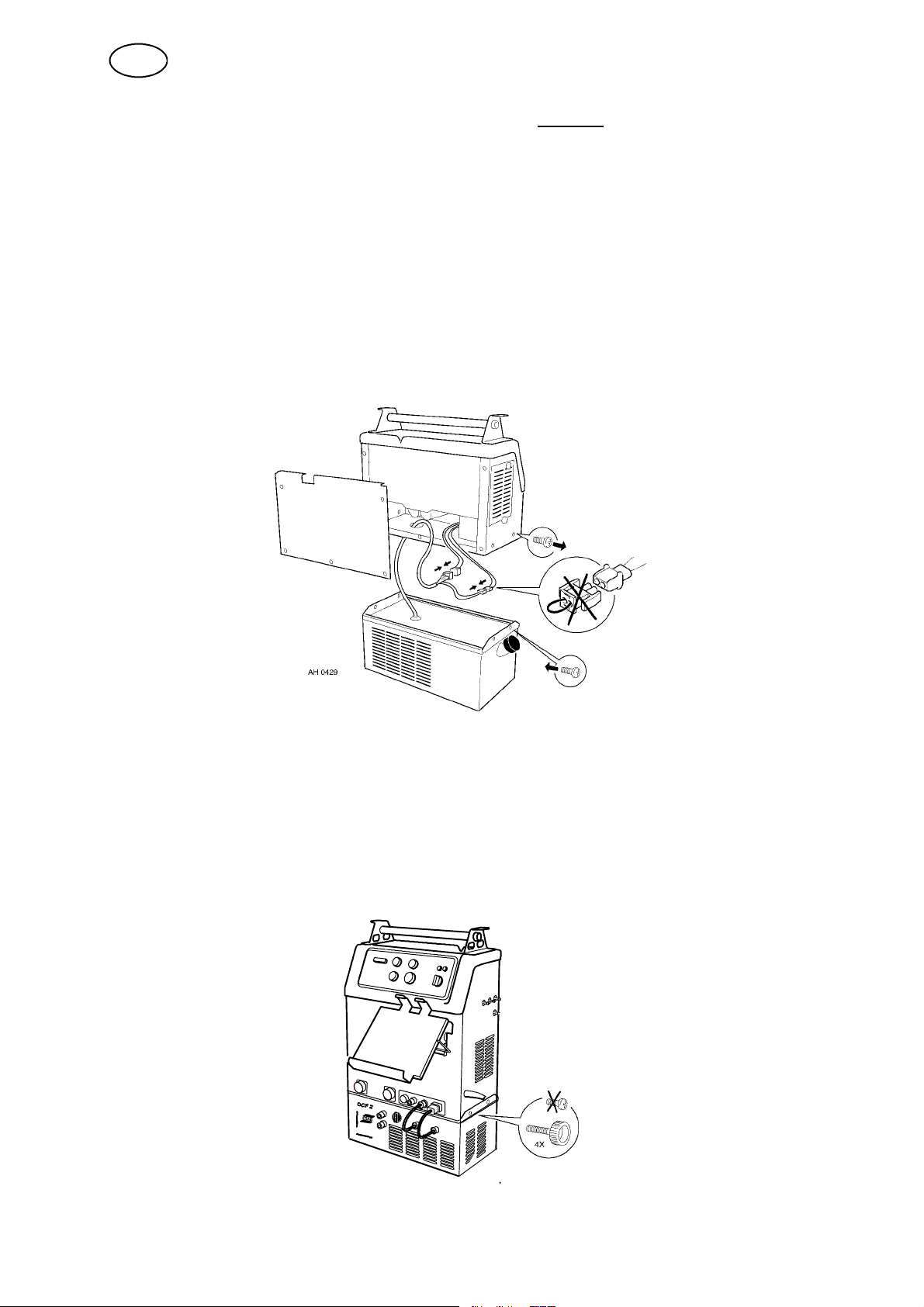
OCF 2L to LTN/LTR 200,255, and OCF 2D to DTE. FITTED with connecting cable
for cooling unit.
1. Unplug if necessary.
2. Remove the lower screws from the sides of the power source.
3. Remove the rear panel from the power source.
4. Remove the spring washer from the bottom panel (only applies to DTE):
5. Place the power source on the cooling unit and raise the rear edge.
6. Feed the connectors from the cooling unit through the hole in the bottom panel.
7. Remove the clamp from the terminal inside the p ower source and join the
connectors see fig.3.
8. Refit the rear panel.
9. Tighten the screws in the bottom through the cover on the cooling unit.
10. Connect the water--cooled torch and do a test run.
fig.3
OCF 2M to LTS 160/250.
1. Unplug if necessary.
2. Remove the lower cross--head screws from the sides of the power source.
3. Place the power source on the cooling unit.
4. Tighten the knobs (M5) at the sides through the cover of the cooling unit.
5. Connect the power cable and the flow monitor to the power source.
6. Connect the water--cooled torch and do a test run.
bk02d13e
-- 7 --
Page 8
GB
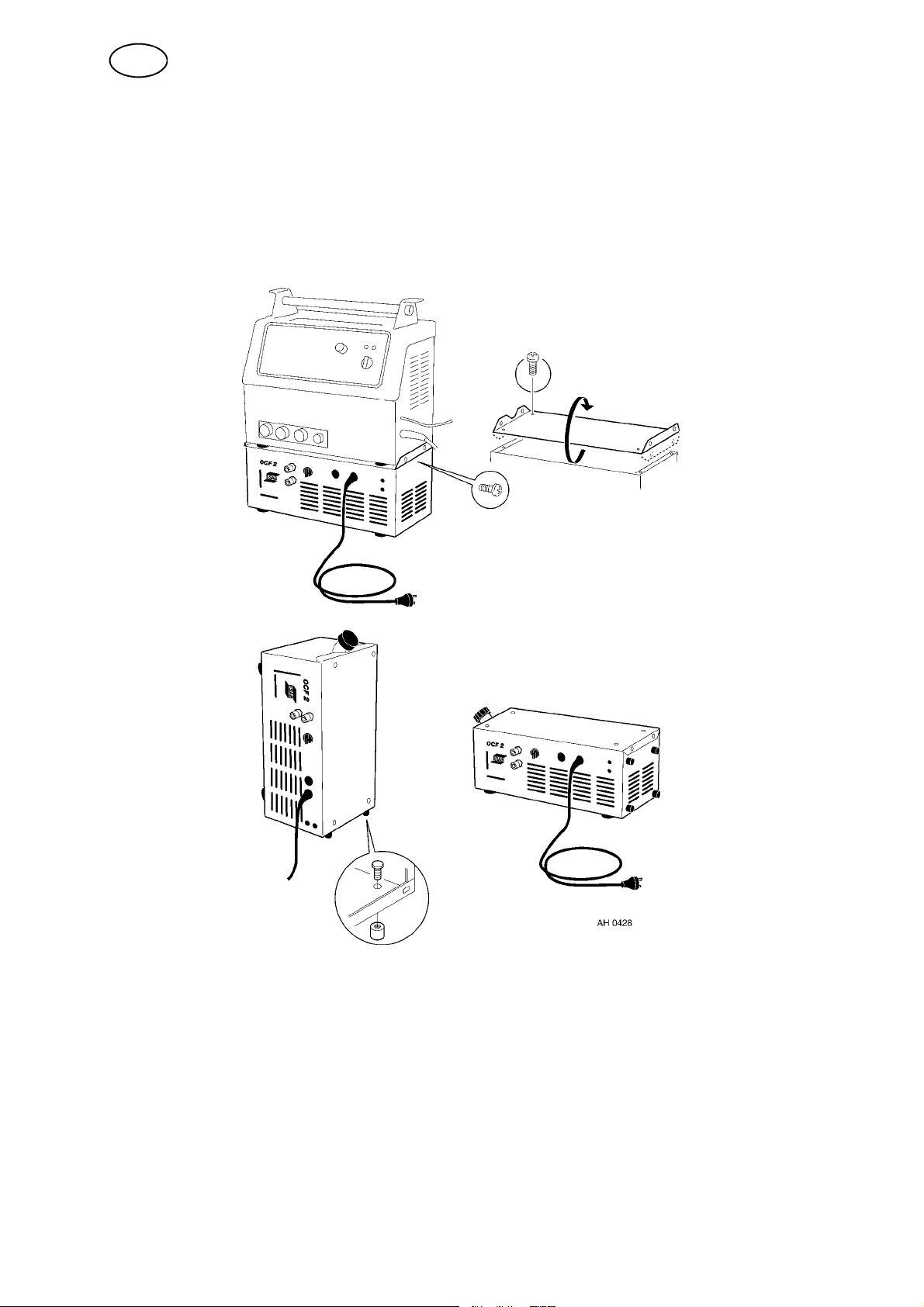
OCF 2A to LTN/LTR 160.
1. Remove the lower cross--head screws from the sides of the power source.
2. Place the power source on the cooling unit.
3. Tighten the screws in the bottom through the cover on the cooling unit.
4. Plug the power cable into an earthed wall socket 230 V, 6 A.
5. Connect the water--cooled torch and do a test run.
OCF 2A free--standing
1. If the cooling unit is to stand upright, fit the feet to the right side panel.
2. Turn the cover upside down to provide a flat surface and screw it in place with
M5 screws.
3. Place the cooling unit on its side or stand it upright, secure with M5 screws.
4. Fit an earthed plug. (the existing plug complies with Swedish regulations)
5. Plug the power cable into an earthed wall socket 230 V, 6 A.
6. Connect the water--cooled torch and do a test run.
bk02d13e
-- 8 --
Page 9
GB
6OPERATION
Glycol
The cooling unit contains poisonous glycol which must not be drunk or poured down
the drain or into the soil or water. Regularly top up the tank to a level 1 cm below the
top if water is lost during hose changes.
Avoid using glycol if the conditions are not cold enough to warrant it.
Pure water gives the best cooling effect.
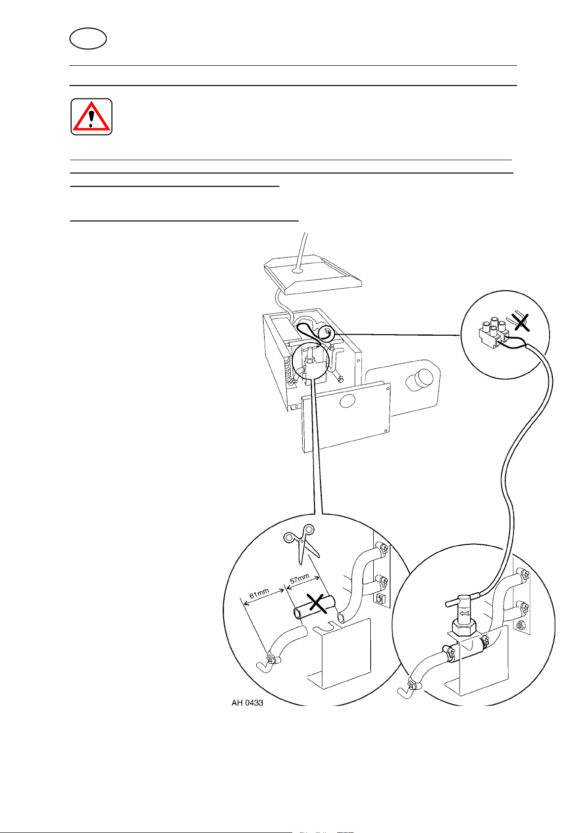
6.1 Flow monitor
Applies to OCF 2M and options.
The flow monitor is connected in series with
the thermal cut--out inside the power source.
If the water flow is restricted or stopped this
will trigger the flow monitor and prevent
further welding.
bk02d13e
-- 9 --
Page 10
GB
7 MAINTENANCE
Note!
All guarantee undertakings from the supplier cease to apply if the customer himself
attempts any work in the product during the guarantee period in order to rectify any
faults.
7.1 Inspection and cleaning
The flow of air through the cooling unit carries small particles that stick to the cooling
element, especially in a dirty working environment. This can reduce cooling
performance. You should therefore clean the element regularly using compressed
air.
Replace the coolant about once a year. Refill with glycol mixture if the cooling unit is
to be used or stored in freezing conditions.
8 TROUBLESHOOTING
In case of major faults, contact your nearest ESAB authorised service workshop or
dealer.
Fault Action
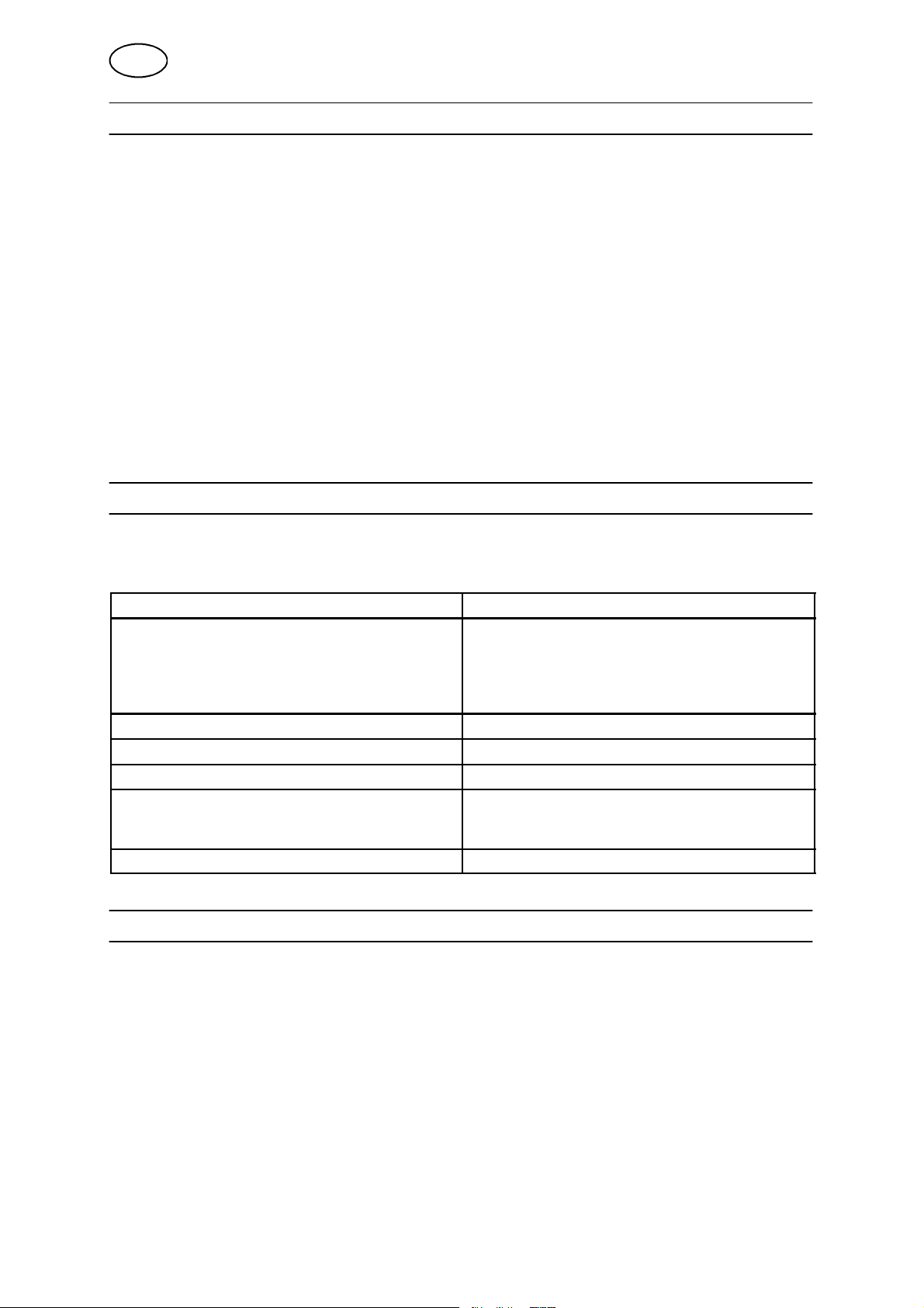
Thermal cut--out lamp on power source comes
on
Pump or fan not working S Check both fuses
Pump not working S Major fault, see above.
Fan not working S Major fault, see above.
No water flow S Raise left panel.
Poor cooling effect S Clean cooling element with compressed air
S Check cooling unit is running.
S Check that safety plug is fitted.
S If water is flowing, the flow monitor may be
faulty, counts as major fault, see above.
Switch off, disconnect blue coupling, blow
through coolant hose to empty system.
9 ORDERING SPARE PARTS
Spare parts may be ordered through your nearest ESAB dealer, see the last page of
this publication.
bk02d13e
-- 1 0 --
Page 11
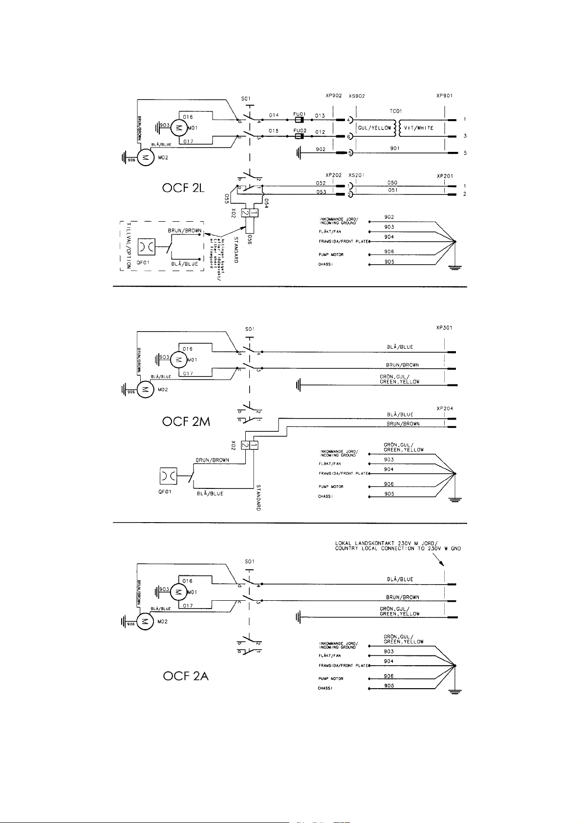
Diagram
Schema 0457 722
bk02e13a
-- 1 1 -Edition 050819
Page 12
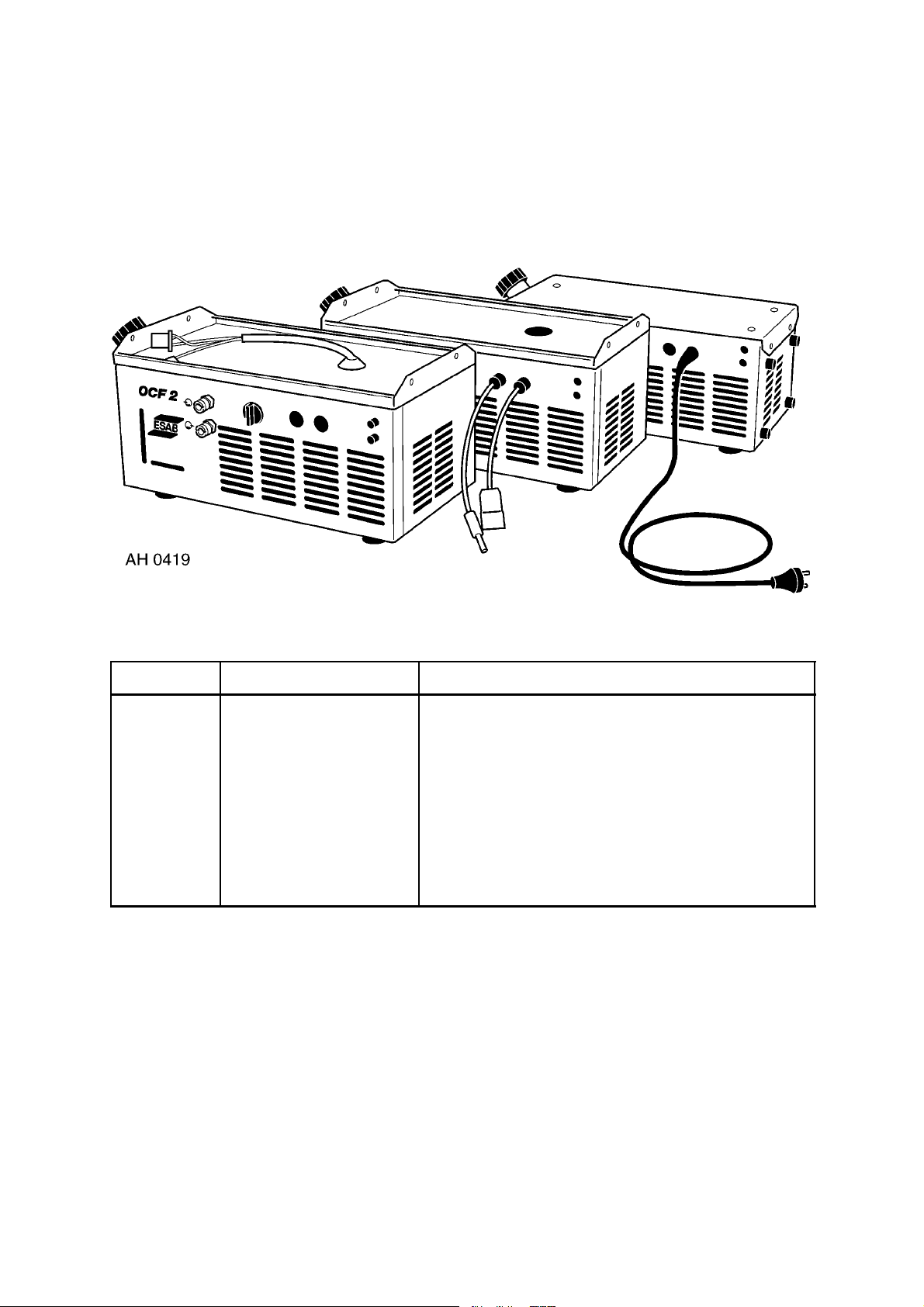
Ordering number
Ordering no. Denomination Type
0457 216 880 Cooling unit OCF 2L
0457 216 881 Cooling unit OCF 2D
0457 216 882 Cooling unit OCF 2M
0457 216 883 Cooling unit OCF 2A
0457 816 880 Conversion kit For LTN / LTR 200, 255 not fitted with connectiong
cable for cooling unit OCF 2L
0457 680 990 Spare parts list OCF 2L, OCF 2D, OCF 2M, OCF 2A
The spare parts list is available on the Internet at www.esab.com
Under ”Products” and ”Welding & cutting equipment”, you will find a link to the page where you can
both search for and download instruction manuals and spare parts lists.
bk02o
-- 1 2 -Edition 050819
Page 13

p
-- 1 3 --
Page 14
ESAB subsidiaries and representative offices
Europe
AUSTRIA
ESAB Ges.m.b.H
Vienna--Liesing
Tel: +43 1 888 25 11
Fax: +43 1 888 25 11 85
BELGIUM
S.A. ESAB N.V.
Brussels
Tel: +32 2 745 11 00
Fax: +32 2 745 11 28
THE CZECH REPUBLIC
ESAB VAMBERK s.r.o.
Prague
Tel: +420 2 819 40 885
Fax: +420 2 819 40 120
DENMARK
Aktieselskabet ESAB
Copenhagen--Valby
Tel:+4536300111
Fax:+4536304003
FINLAND
ESAB Oy
Helsinki
Tel: +358 9 547 761
Fax: +358 9 547 77 71
FRANCE
ESAB France S.A.
Cergy Pontoise
Tel:+33130755500
Fax:+33130755524
GERMANY
ESAB GmbH
Solingen
Tel: +49 212 298 0
Fax: +49 212 298 218
GREAT BRITAIN
ESAB Group (UK) Ltd
Waltham Cross
Tel: +44 1992 76 85 15
Fax: +44 1992 71 58 03
ESAB Automation Ltd
Andover
Tel: +44 1264 33 22 33
Fax: +44 1264 33 20 74
HUNGARY
ESAB Kft
Budapest
Tel:+3612044182
Fax:+3612044186
ITALY
ESAB Saldatura S.p.A.
Mesero (Mi)
Tel:+3902979681
Fax:+390297289181
THE NETHERLANDS
ESAB Nederland B.V.
Utrecht
Tel: +31 30 2485 377
Fax: +31 30 2485 260
NORWAY
AS ESAB
Larvik
Tel:+4733121000
Fax:+4733115203
POLAND
ESAB Sp.zo.o.
Katowice
Tel: +48 32 351 11 00
Fax: +48 32 351 11 20
PORTUGAL
ESAB Lda
Lisbon
Tel: +351 8 310 960
Fax: +351 1 859 1277
SLOVAKIA
ESAB Slovakia s.r.o.
Bratislava
Tel:+421744882426
Fax:+421744888741
SPAIN
ESAB Ibérica S.A.
Alcalá de Henares (MADRID)
Tel: +34 91 878 3600
Fax: +34 91 802 3461
SWEDEN
ESAB Sverige AB
Gothenburg
Tel:+4631509500
Fax:+4631509222
ESAB International AB
Gothenburg
Tel:+4631509000
Fax:+4631509360
SWITZERLAND
ESAB AG
Dietikon
Tel: +41 1 741 25 25
Fax: +41 1 740 30 55
North and South America
ARGENTINA
CONARCO
Buenos Aires
Tel: +54 11 4 753 4039
Fax: +54 11 4 753 6313
BRAZIL
ESAB S.A.
Contagem-- MG
Tel: +55 31 2191 4333
Fax: +55 31 2191 4440
CANADA
ESAB Group Canada Inc.
Missisauga, Ontario
Tel: +1 905 670 02 20
Fax: +1 905 670 48 79
MEXICO
ESAB Mexico S.A.
Monterrey
Tel: +52 8 350 5959
Fax: +52 8 350 7554
USA
ESAB Welding & Cutting Products
Florence, SC
Tel: +1 843 669 44 11
Fax: +1 843 664 57 48
Asia/Pacific
CHINA
Shanghai ESAB A/P
Shanghai
Tel: +86 21 5308 9922
Fax: +86 21 6566 6622
INDIA
ESAB India Ltd
Calcutta
Tel: +91 33 478 45 17
Fax: +91 33 468 18 80
INDONESIA
P.T. ESABindo Pratama
Jakarta
Tel: +62 21 460 0188
Fax: +62 21 461 2929
JAPAN
ESAB Japan
Tokyo
Tel: +81 3 5296 7371
Fax: +81 3 5296 8080
MALAYSIA
ESAB (Malaysia) Snd Bhd
Shah Alam Selangor
Tel: +60 3 5511 3615
Fax: +60 3 5512 3552
SINGAPORE
ESAB Asia/Pacific Pte Ltd
Singapore
Tel:+6568614322
Fax: +65 6861 31 95
SOUTH KOREA
ESAB SeAH Corporation
Kyungnam
Tel: +82 55 269 8170
Fax: +82 55 289 8864
UNITED ARAB EMIRATES
ESAB Middle East FZE
Dubai
Tel: +971 4 887 21 11
Fax: +971 4 887 22 63
Representative offices
BULGARIA
ESAB Representative Office
Sofia
Tel/Fax: +359 2 974 42 88
EGYPT
ESAB Egypt
Dokki--Cairo
Tel: +20 2 390 96 69
Fax: +20 2 393 32 13
ROMANIA
ESAB Representative Office
Bucharest
Tel/Fax: +40 1 322 36 74
RUSSIA-- CIS
ESAB Representative Office
Moscow
Tel:+70959379820
Fax: +7 095 937 95 80
ESAB Representative Office
St Petersburg
Tel:+78123254362
Fax: +7 812 325 66 85
Distributors
For addresses and phone
numbers to our distributors in
other countries, please visit our
home page
www.esab.com
ESAB AB
SE-- 695 81 LAXÅ
SWEDEN
Phone +46 584 81 000
www.esab.com
041227
 Loading...