

Page 1
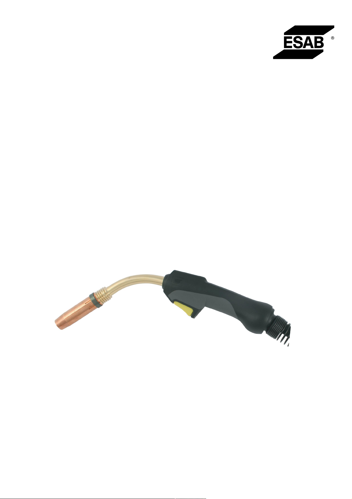
MXL201 MXL411W
MXL271MXL511W
MXL341
Instruction manual
0463 633 001 GB 20181105
Page 2
Page 3

TABLE OF CONTENTS
1
SAFETY ....................................................................................................... 4
1.1 Meaning of symbols ............................................................................... 4
1.2 Safety precautions ................................................................................. 4
2
INTRODUCTION.......................................................................................... 7
3
SHIPMENT AND PACKAGING ................................................................... 8
4
TECHNICAL DATA ...................................................................................... 9
5
OPERATION ................................................................................................ 11
5.1 Fitting the linear...................................................................................... 11
5.2 Equipping the torch................................................................................ 11
5.3 Fitting the central adaptor to the equipment ....................................... 11
5.4 Connecting the cooling circuit.............................................................. 11
5.5 Setting the level of shielding gas.......................................................... 12
5.6 Checklist ................................................................................................. 12
5.7 Changing wire......................................................................................... 12
5.8 Starting and stopping the welding process......................................... 12
6
MAINTENANCE........................................................................................... 13
6.1 Overview ................................................................................................. 13
6.2 Cable assembly ...................................................................................... 13
6.3 Cleaning the wire feed ........................................................................... 13
6.4 Steel liner / Plastic liner ......................................................................... 13
6.5 Cleaning the swan neck......................................................................... 15
6.6 Checking the cooling system................................................................ 15
7
TROUBLESHOOTING................................................................................. 16
8
ORDERING SPARE PARTS........................................................................ 17
ORDERING NUMBERS ....................................................................................... 18
SPARE PARTS LIST............................................................................................ 19
WEAR PARTS...................................................................................................... 21
Rights reserved to alter specifications without notice.
0463 633 001 © ESAB AB 2018
Page 4
1 SAFETY
1 SAFETY
1.1 Meaning of symbols
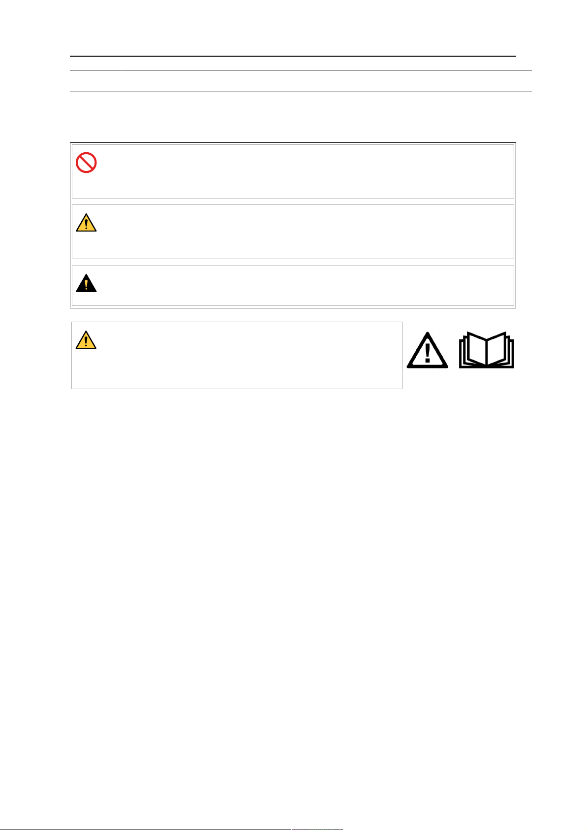
As used throughout this manual: Means Attention! Be Alert!
DANGER!
Means immediate hazards which, if not avoided, will result in immediate,
serious personal injury or loss of life.
WARNING!
Means potential hazards which could result in personal injury or loss of
life.
CAUTION!
Means hazards which could result in minor personal injury.
WARNING!
Before use, read and understand the instruction manual
and follow all labels, employer´s safety practices and Safety
Data Sheets (SDSs).
1.2 Safety precautions
Users of ESAB equipment have the ultimate responsibility for ensuring that anyone who
works on or near the equipment observes all the relevant safety precautions. Safety
precautions must meet the requirements that apply to this type of equipment. The following
recommendations should be observed in addition to the standard regulations that apply to
the workplace.
All work must be carried out by trained personnel well-acquainted with the operation of the
equipment. Incorrect operation of the equipment may lead to hazardous situations which can
result in injury to the operator and damage to the equipment.
1. Anyone who uses the equipment must be familiar with:
○ its operation
○ location of emergency stops
○ its function
○ relevant safety precautions
○ welding and cutting or other applicable operation of the equipment
2. The operator must ensure that:
○ no unauthorised person is stationed within the working area of the equipment
when it is started up
○ no-one is unprotected when the arc is struck or work is started with the
equipment
3. The workplace must:
○ be suitable for the purpose
○ be free from drafts
0463 633 001
- 4 -
© ESAB AB 2018
Page 5
1 SAFETY
4. Personal safety equipment:
○ Always wear recommended personal safety equipment, such as safety glasses,
flame-proof clothing, safety gloves
○ Do not wear loose-fitting items, such as scarves, bracelets, rings, etc., which
could become trapped or cause burns
5. General precautions:
○ Make sure the return cable is connected securely
○ Work on high voltage equipment may only be carried out by a qualified
electrician
○ Appropriate fire extinguishing equipment must be clearly marked and close at
hand
○ Lubrication and maintenance must not be carried out on the equipment during
operation
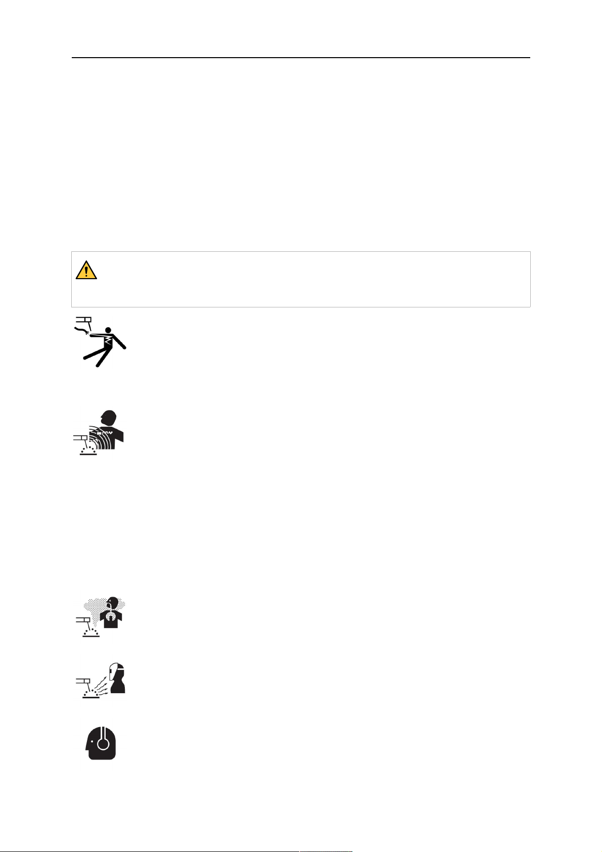
WARNING!
Arc welding and cutting can be injurious to yourself and others. Take precautions
when welding and cutting.
ELECTRIC SHOCK - Can kill
• Install and ground the unit in accordance with instruction manual.
• Do not touch live electrical parts or electrodes with bare skin, wet gloves or
wet clothing.
• Insulate yourself from work and ground.
• Ensure your working position is safe
ELECTRIC AND MAGNETIC FIELDS - Can be dangerous to health
• Welders having pacemakers should consult their physician before welding.
EMF may interfere with some pacemakers.
• Exposure to EMF may have other health effects which are unknown.
• Welders should use the following procedures to minimize exposure to
EMF:
○ Route the electrode and work cables together on the same side of
your body. Secure them with tape when possible. Do not place your
body between the torch and work cables. Never coil the torch or work
cable around your body. Keep welding power source and cables as
far away from your body as possible.
○ Connect the work cable to the workpiece as close as possible to the
area being welded.
FUMES AND GASES - Can be dangerous to health
• Keep your head out of the fumes.
• Use ventilation, extraction at the arc, or both, to take fumes and gases
away from your breathing zone and the general area.
ARC RAYS - Can injure eyes and burn skin
• Protect your eyes and body. Use the correct welding screen and filter lens
and wear protective clothing.
• Protect bystanders with suitable screens or curtains.
0463 633 001
NOISE - Excessive noise can damage hearing
Protect your ears. Use earmuffs or other hearing protection.
- 5 -
© ESAB AB 2018
Page 6
1 SAFETY
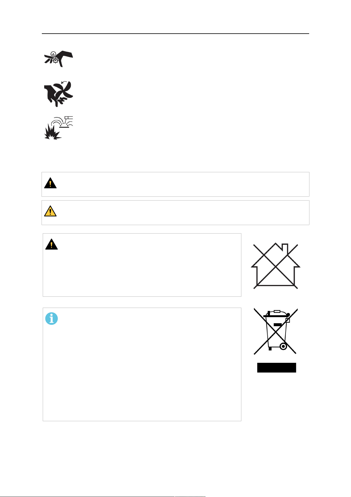
MOVING PARTS - Can cause injuries
• Keep all doors, panels and covers closed and securely in place. Have only
qualified people remove covers for maintenance and troubleshooting as
necessary. Reinstall panels or covers and close doors when service is
finished and before starting engine.
• Stop engine before installing or connecting unit.
• Keep hands, hair, loose clothing and tools away from moving parts.
FIRE HAZARD
• Sparks (spatter) can cause fire. Make sure that there are no inflammable
materials nearby.
• Do not use on closed containers.
MALFUNCTION - Call for expert assistance in the event of malfunction.
PROTECT YOURSELF AND OTHERS!
CAUTION!
This product is solely intended for arc welding.
WARNING!
Do not use the power source for thawing frozen pipes.
CAUTION!
Class A equipment is not intended for use in residential
locations where the electrical power is provided by the
public low-voltage supply system. There may be potential
difficulties in ensuring electromagnetic compatibility of class
A equipment in those locations, due to conducted as well
as radiated disturbances.
NOTE!
Dispose of electronic equipment at the recycling
facility!
In observance of European Directive 2012/19/EC on Waste
Electrical and Electronic Equipment and its implementation
in accordance with national law, electrical and/or electronic
equipment that has reached the end of its life must be
disposed of at a recycling facility.
As the person responsible for the equipment, it is your
responsibility to obtain information on approved collection
stations.
For further information contact the nearest ESAB dealer.
ESAB has an assortment of welding accessories and personal protection equipment
for purchase. For ordering information contact your local ESAB dealer or visit us on
our website.
0463 633 001
- 6 -
© ESAB AB 2018
Page 7

2 INTRODUCTION
2 INTRODUCTION
The MIG / MAG welding torches of this series are exclusively intended for shielded- arc
welding using inert gas (MIG) or active gas (MAG) for industrial and commercial use by
suitably trained employees. The torches are only available in manual versions.
0463 633 001
- 7 -
© ESAB AB 2018
Page 8

3 SHIPMENT AND PACKAGING
3 SHIPMENT AND PACKAGING
The components are carefully checked and packaged, however damage may occur during
shipping.
Checking procedure on receipt of goods
Check that the shipment is correct by referring to the shipping note.
In case of damage
Check the package and components for damage (visual inspection).
In case of complaints
Check the package and components for damage (visual inspection).
• Contact with the last carrier immediately.
• Keep the packaging (for possible inspection by the carrier or supplier, or for returning
the goods).
Storage in an enclosed space
Ambient temperature for shipment and storage: -20 °C to +55 °C
Relative air humidity: up to 90% at a temperature of 20 °C
0463 633 001
- 8 -
© ESAB AB 2018
Page 9
4 TECHNICAL DATA
4 TECHNICAL DATA
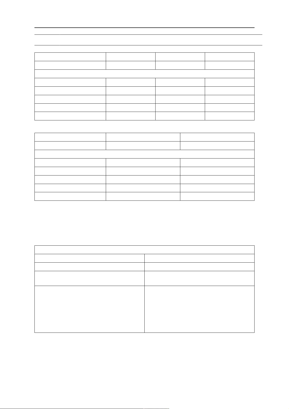
Welding torch MXL 201 MXL 271 MXL 341
Type of cooling Air Air Air
Permitted load at 60% duty cycle*
Carbon dioxide CO2 160 A 230 A 330 A
Mixed gas, Ar/CO2 M21 150 A 210 A 300 A
Recommended gas flow 8-12 l/min 8-15 l/min 10-18 l/min
Wire diameter 0.6-1.0 mm 0.8-1.2 mm 1.0-1.6 mm
Operating temperature** -10 °C to 40 °C -10 °C to 40 °C -10 °C to 40 °C
* The capacity may be reduced up to 30% when pulse welding.
Welding torch MXL 411W MXL 511W
Type of cooling Water Water
Permitted load at 100% duty cycle*
Carbon dioxide CO2 400 A 500 A
Mixed gas, Ar/CO2 M21 350 A 450 A
Recommended gas flow 10-20 l/min 10-20 l/min
Wire diameter 1.0-1.6 mm 1.0-1.6 mm
Operating temperature** -10 °C to 40 °C -10 °C to 40 °C
* The capacity may be reduced up to 30% when pulse welding.
** When using liquid cooled torches in freezing conditions, use an adequate cooling liquid.
Duty cycle
The duty cycle refers to the time as a percentage of a ten-minute period that you can weld at
a certain load without overloading. The duty cycle is valid for 40 °C / 104 °F, or below.
General torch data with reference to IEC/EN 60 974−7
Type of guidance: Manual
Wire type: Standard round wire
Voltage rating: The control circuit and trigger switch are
rated for a voltage of 42 V, max. 1 A
Specifications of the torch cooling circuit (for
liquid cooled torches only):
• minimum flow 1.2 l/min
• min. water pressure: 2.5 bar
• max. water pressure: 3.5 bar
• input temperature: max. 40 °C
• return temperature: max. 60 °C
• cooling capacity: min. 1000 W, up to
2000 W depending on the application
Liquid cooled torches
Return temperatures of more than 60 °C can shorten the lifetime of the torch or cause
damage or destruction of the torch. The cooler must always be filled with sufficient cooling
liquid, refer to the instruction manual for the cooling unit. In case of a high thermal load on
the torch, use a cooler with sufficient capacity. Use only special cooling fluid containing
corrosion inhibitors for welding torches. For suitable products, contact your nearest ESAB
dealer.
0463 633 001
- 9 -
© ESAB AB 2018
Page 10

4 TECHNICAL DATA
The ratings are valid for cable lengths from 3.0 to 5.0 m.
The rated loads refer to a standardized case of use. Under special conditions, e.g. in case of
high heat reflection on the torch, the torch could overheat even when operated below the
rated load. In this case choose a more powerful model or lower the duty cycle.
Conditions of intended use
1. The welding torch should only be used within the above mentioned technical
specifications and for its intended purpose.
2. The type of torch has to be chosen according to the welding application. The required
duty-cycle and load, the type of cooling, guiding method and the wire diameter have to
be considered. If increased requirements exist, for example caused by pre-heated
work pieces, high heat reflection in corners, etc. these must be taken into account by
choosing a welding torch with adequate reserve in rated load.
3. The product must be protected from humidity and moisture during transport, storage
and operation.
0463 633 001
- 10 -
© ESAB AB 2018
Page 11
5 OPERATION
5 OPERATION
General safety regulations for handling the equipment can be found in the "SAFETY"
chapter of this manual. Read it through before you start using the equipment!
CAUTION!
This product is intended for industrial use. In a domestic environment this product
may cause radio interference. It is the user's responsibility to take adequate
precautions.
DANGER!
In the event of an emergency, the power source must be switched off
immediately. For further action in such circumstances, refer to the instruction
manual of the power source for more information.
The welding torch can be used in any welding position.
Contact with hot items might cause damage to the torch and the cable assembly.
Do not drag the power source using the torch.
Do not pull the cable assembly over sharp edges. Do not bend the cable assembly sharply.
5.1 Fitting the linear
Fit the correct wire guide liner for the application, as needed to suit the wire type and
diameter. See chapter "MAINTENANCE" section "Steel liner / Plastic liner".
NOTE!
For information on how to install new liners and about correct assembly
procedure, see the chapter entitled “Maintenance”
Steel liner = for steel wires
Plastic liner = for aluminium, copper, nickel and stainless steel wires
5.2 Equipping the torch
The torch must be equipped according to the wire diameter and wire material. Choose the
right liner, contact tip, tip adaptor, gas nozzle and gas diffuser (as applicable). A detailed
overview of the suitable parts is found in the spare parts list for the torch.
Tighten the tip adaptor and the contact tip with an adequate tool.
Make sure that all required parts shown in the spare parts list, e.g. insulators, are installed.
Welding without these items might cause immediate destruction of the torch.
5.3 Fitting the central adaptor to the equipment
1. Check that the wire guide liner is fitted correctly.
2. Insert the central plug into the socket on the wire feed unit and secure it by tightening
the adaptor nut firmly by hand.
5.4 Connecting the cooling circuit
Connect the water hoses to the cooling unit: blue for water flow forward from the cooler to the
torch; red for heated water flow backwards from the torch to the cooler. Before using a water
cooled torch, the air has to be removed from the cooling circulation by running the cooler for
a few minutes.
0463 633 001
- 11 -
© ESAB AB 2018
Page 12
5 OPERATION
CAUTION!
Wrongly connected water hoses can cause overheating and damage of the torch
neck and water-power cable. Regularly check the coolant level and throughput on
the cooling unit. Insufficient cooling might cause overheating and damage of the
torch neck and water-power cable.
NOTE!
To achieve an optimal gas- and water flow, place the cable assemblies and the
gas and water hoses as straight as possible. Kinked hoses will cause overheating
and can damage the torch. Protect cables and supply hoses from damage.
5.5 Setting the level of shielding gas
Set the quantity of gas required on the gas regulator. The type and quantity of gas to be used
depend on the welding task to be performed.
5.6 Checklist
Check the cable assembly before connecting it to the wire feed unit to confirm the wire liner
is suitable for the wire diameter and type.
Check the front end consumable parts on the swan neck, whether the correct contact tip etc.
is being used for the wire diameter and type.
5.7 Changing wire
When changing the wire, ensure that the end of the wire is deburred.
Insert the wire into the wire feeding unit in accordance with the operating instructions.
When inserting the wire, press the wire jog button on the wire feed unit.
5.8 Starting and stopping the welding process
The wire feeder and the welding process will be started by pulling the torch trigger.
Depending on the configuration of the welding machine, the welding process will be stopped
by either letting go of the trigger or by pulling the trigger a second time. Refer to the
instruction manual for the power source for more information.
DANGER!
The torch head might reach very high temperatures during operation, there is a
risk of severe burns. Let it cool down under observation, there is risk of fire. Do
not place the hot torch on or near heat-sensitive objects. For water cooled
torches, the cooling system should remain switched on for some minutes after
the welding process has been stopped.
When leaving the workplace the system must be secured against unintended
operation, preferably by switching off the power source.
0463 633 001
- 12 -
© ESAB AB 2018
Page 13
6 MAINTENANCE
6 MAINTENANCE
6.1 Overview
NOTE!
Regular maintenance is important for safe and reliable operation.
Cleaning and replacement of the welding torch’s wear parts should take place at regular
intervals in order to achieve trouble−free wire feed. Blow the wire guide clean regularly and
clean the contact tip.
WARNING!
Before carrying out cleaning, servicing and repair work, the following shutdown
procedure must be followed.
1. Switch off the power supply.
2. Close off the gas supply.
Make sure that the power supply and gas remain turned off all the time while
servicing the equipment.
6.2 Cable assembly
Check the torch and cable assembly for damages prior to use. Damages must be repaired by
qualified personnel before further use of the product.
6.3 Cleaning the wire feed
Disconnect the torch cable assembly from the equipment and lay it out straight.
Unscrew the nut and pull out the wire guide liner. Remove other parts from the swan neck.
Blow compressed air through the wire conduit from both ends in order to remove wire
shavings.
Insert the liner into the wire conduit and screw the nut back on.
NOTE!
New liners must be cut to the correct length.
6.4 Steel liner / Plastic liner
If a wire feeding problem cannot be solved by exchanging the contact tip and cleaning the
wire guide channel, the liner should be replaced.
Liner and welding wire should be inserted while the cable assembly is laid out straight.
0463 633 001
- 13 -
© ESAB AB 2018
Page 14
6 MAINTENANCE
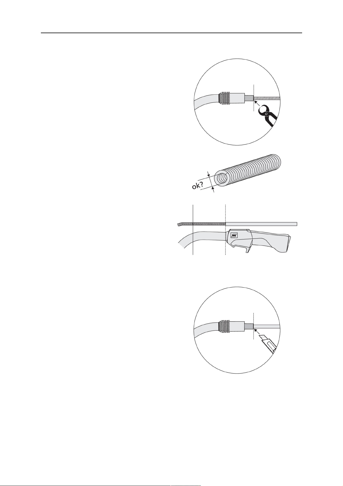
Installing a steel liner
Remove the sleeve nut from the central
connector, remove the gas nozzle and
contact tip from the torch.
Insert the liner through the central connector
and lock it with the sleeve nut.
Cut the liner flush with the tip holder and
chamfer the edges (e.g. with a pencil
sharpener).
For MXL 271 only: Remove the tip holder
and cut the liner flush with the front end of the
neck.
Remove the liner from the torch and carefully
smoothen its front end. If needed, grind down
burred edges. Make sure the inner hole is
completely open.
For insulated liners, remove the insulation at
the front end so that the remaining insulation
ends approximately at the front end of the
torch handle.
Reinstall the liner and lock it with the sleeve
nut. Install all equipment parts on the torch
neck.
Installing a plastic liner
Remove the sleeve nut from the central
connector, remove the gas nozzle and
contact tip from the torch.
Insert the liner through the central connector
and lock it with the sleeve nut.
Cut the liner flush with the tip holder and
chamfer the edges (e.g. with a pencil
sharpener).
For MXL 271 only: Remove the tip holder
and cut the liner flush with the front end of the
neck.
0463 633 001
- 14 -
© ESAB AB 2018
Page 15
6 MAINTENANCE
If it is difficult to insert the liner into the torch,
make a clean cut at the front end of the liner
and chamfer the edges (e.g. with a pencil
sharpener).
Install the gas nozzle and contact tip on the
torch.
NOTE!
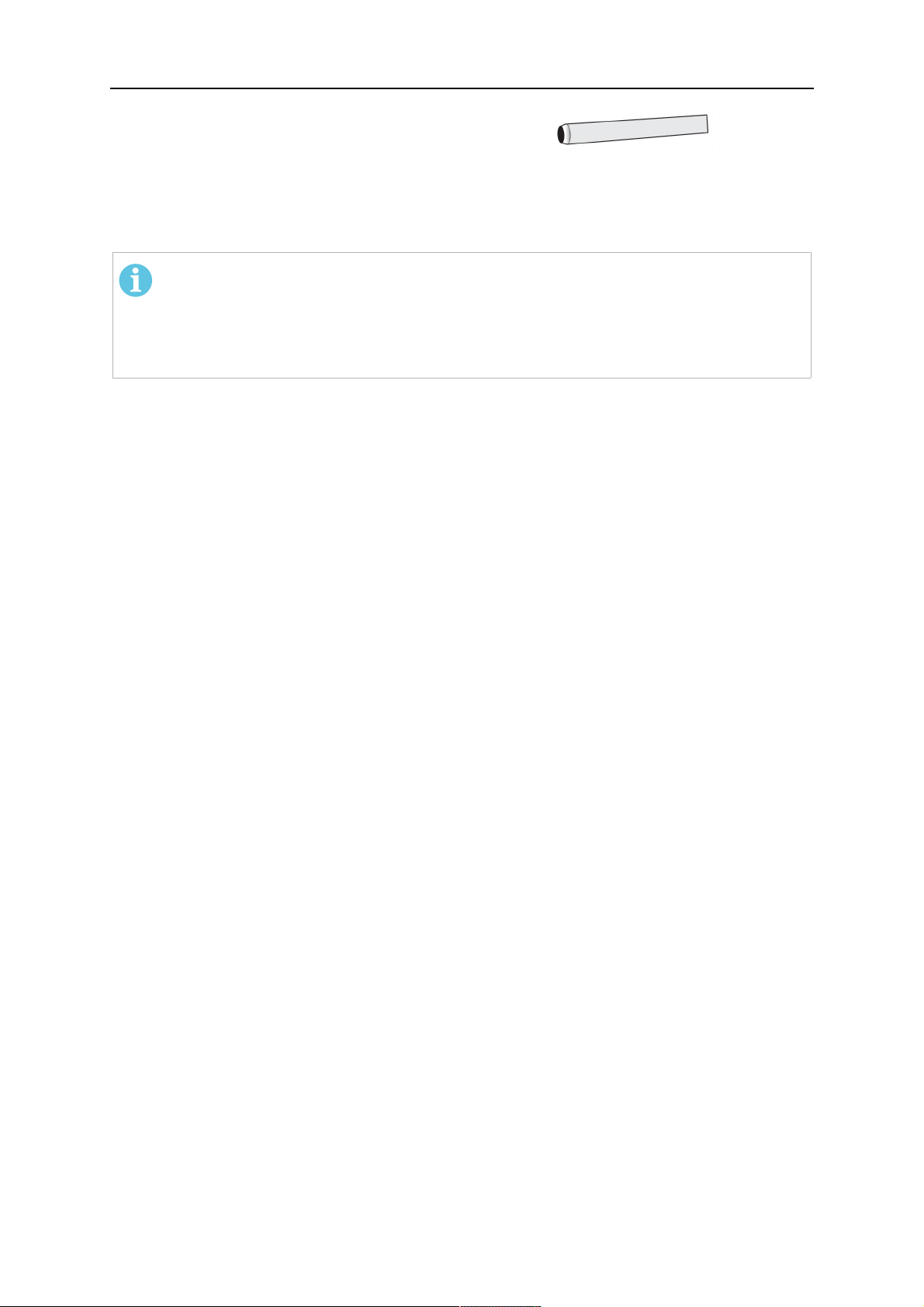
If the liner has a bronze front end, first cut the plastic liner to a suitable length
and let the bronze liner stick out approximately 40–50 mm from the torch neck.
Attach the bronze liner to the front of the plastic liner and only then cut this liner
assembly to the precise length.
6.5 Cleaning the swan neck
• Clean the inside of the gas nozzle regularly to remove welding spatter and spray with
ESAB® anti-spatter agent.
• Check the consumables for visible damage and replace if necessary.
6.6 Checking the cooling system
Make sure that the cooling liquid is clean, change it if required. Impurities in the cooling liquid
can obstruct the water channels of the torch. Always use suitable cooling fluid for torches
with corrosion inhibitors.
0463 633 001
- 15 -
© ESAB AB 2018
Page 16

7 TROUBLESHOOTING
7 TROUBLESHOOTING
If the measures described below are not successful, consult your dealer or the manufacturer.
Read the operating instructions for the welding components, e.g. power source and wire feed
unit.
Problem Possible cause Action
Torch becomes too hot • Contact tip / tip holder
not tight enough
• Cooling system is not
working well
• Torch overstrained
• Cable assembly
defective
Wire feeding problems • Contact tip is worn
• Liner is worn / dirty
• Consumables used are
not suitable for the wire
diameter or material
• Wire feeder not set-up
properly
• Cable assembly is bent
or laid out in small radii
• Wire is contaminated
• Check and tighten
hand-tight
• Check water flow, filling
level and cleanliness
• Observe technical data,
if needed, choose a
different type
• Check cables, tubes
and connections
• Exchange contact tip
• Check the liner, blow
through in both
directions. Exchange if
needed.
• Check with spare part
list
• Check the wire feeding
rolls, the contact
pressure and the spool
brake
• Check the cable
assembly and lay it out
straight
• Use a cleaning felt
Porous welds • Gas swirl caused by
spatter adherence
• Too small or extremely
high gas flow in the
torch
• Gas supply defective
• Air draft at the work
place
• Moisture or
contamination on the
wire or on the work
piece
Variable arc • Contact tip is worn
• Wrong welding
parameters
Welding process does not
start
• Control cable is broken
or the trigger is
defective
• Clean the torch head,
use gas diffuser /
spatter protection
• Check flow rate with
measurement tool
• Check flow rate and
possible leakage
• Install shielding
• Check the wire and the
work piece, use less or
different anti-spatter
liquid
• Exchange contact tip
• Correct the welding
parameters
• Check and repair the
trigger connections,
clean the trigger switch
or exchange it
0463 633 001
- 16 -
© ESAB AB 2018
Page 17
8 ORDERING SPARE PARTS
8 ORDERING SPARE PARTS
CAUTION!
Repair and electrical work should be performed by an authorised ESAB service
technician. Use only ESAB original spare and wear parts.
The MXL 201, MXL 271, MXL 341, MXL 411W and MXL 511W are designed and tested in
accordance with international and European standards IEC/EN 60974-7. On completion of
service or repair work, it is the responsibility of the person(s) performing the work to ensure
that the product still complies with the requirements of the above standard.
Spare parts and wear parts can be ordered through your nearest ESAB dealer, see
esab.com. When ordering, please state product type, serial number, designation and spare
part number in accordance with the spare parts list. This facilitates dispatch and ensures
correct delivery.
0463 633 001
- 17 -
© ESAB AB 2018
Page 18
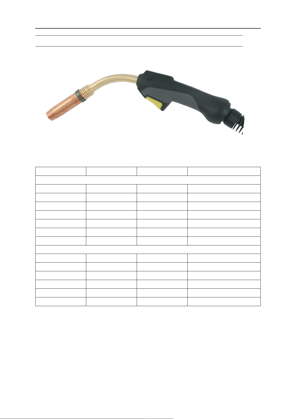
ORDERING NUMBERS
ORDERING NUMBERS
Ordering number Denomination Type Notes
Gas cooled torches
0700 025 220 MXL 201 Welding torch 3 m Euro-Central connector
0700 025 221 MXL 201 Welding torch 4 m Euro-Central connector
0700 025 230 MXL 271 Welding torch 3 m Euro-Central connector
0700 025 231 MXL 271 Welding torch 4 m Euro-Central connector
0700 025 240 MXL 341 Welding torch 3 m Euro-Central connector
0700 025 241 MXL 341 Welding torch 4 m Euro-Central connector
0700 025 242 MXL 341 Welding torch 5 m Euro-Central connector
Water cooled torches
0700 025 250 MXL 411W Welding torch 3 m Euro-Central connector
0700 025 251 MXL 411W Welding torch 4 m Euro-Central connector
0700 025 252 MXL 411W Welding torch 5 m Euro-Central connector
0700 025 260 MXL 511W Welding torch 3 m Euro-Central connector
0700 025 261 MXL 511W Welding torch 4 m Euro-Central connector
0700 025 262 MXL 511W Welding torch 5 m Euro-Central connector
0463 633 001
- 18 -
© ESAB AB 2018
Page 19
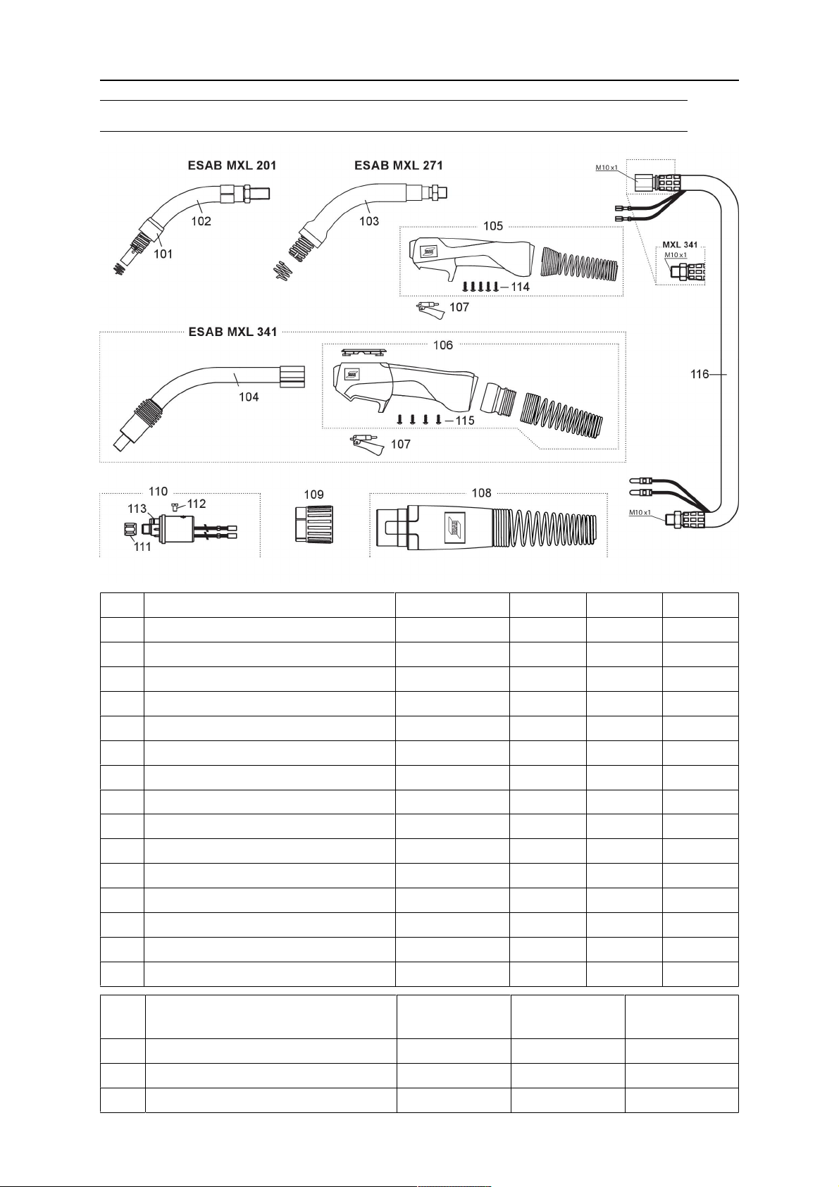
SPARE PARTS LIST
SPARE PARTS LIST
Item Denomination Ordering no. MXL 201 MXL 271 MXL 341
101 Head insulator 0700 200 096 X
102 Torch neck MXL 201 0700 025 200 X
103 Torch neck MXL 271 0700 025 201 X
104 Torch neck MXL 341 0700 025 202 X
105 Handle complete Expert Mini 0700 025 900 X X
106 Handle complete Expert Plus 0700 025 901 X
107 Trigger, yellow, 2-poles 0700 025 903 X X X
108 Cable support cpl. 0700 025 950 X X X
109 Adaptor nut 0700 025 951 X X X
110 Central connector G 0700 200 101 X X X
111 Liner locking nut 0700 200 098 X X X
112 Cylinder head screw M4 x 6 0700 025 952 X X X
113 O-ring 4.0 x 1.0 mm (gas nipple) 0700 025 953 X X X
114 Screw for Expert Mini handle 0700 025 904 X X
115 Screw for Expert Plus handle 0700 025 904 X
Item Denomination Ordering no. /
3 m
Ordering no. /
4 m
Ordering no. /
5 m
116 Coaxial cable for MXL 201 0700 025 960 0700 025 961 -
- Coaxial cable for MXL 271 0700 025 962 0700 025 963 -
- Coaxial cable for MXL 341 0700 025 964 0700 025 965 0700 025 966
0463 633 001
- 19 -
© ESAB AB 2018
Page 20
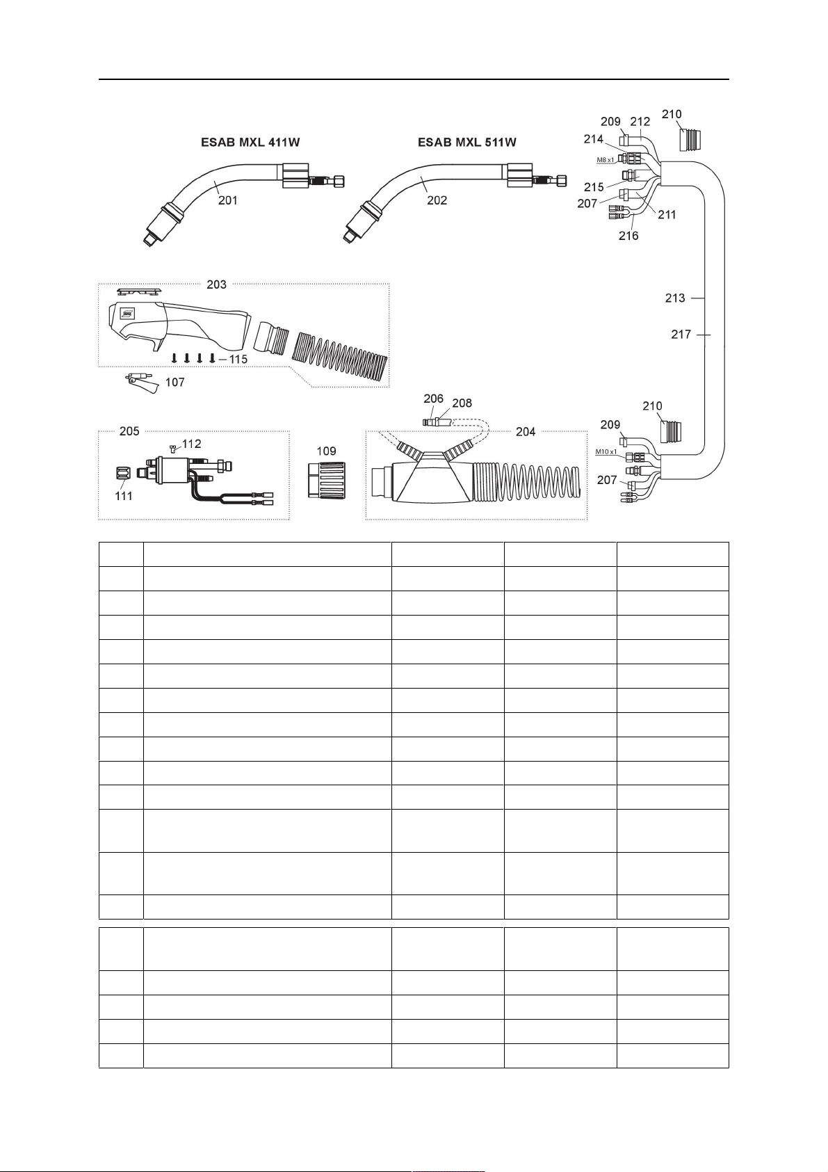
SPARE PARTS LIST
Item Denomination Ordering no. MXL 411 MXL 511
201 Torch neck MXL 411W 0700 025 203 X
202 Torch neck MXL 511W 0700 025 204 X
203 Handle complete Expert Plus 0700 025 902 X X
204 Cable support cpl. 0700 025 971 X X
205 Central connector W 0700 025 970 X X
206 Quick connector 0700 025 973 X X
207 Hose clamp with ring Ø 8.7 0700 025 974 X X
208 Hose clamp with ring Ø 9.0 0700 025 975 X X
209 Hose clamp with ring Ø 9.5 0700 025 976 X X
210 Clamping ring for outer cover 0700 025 972 X X
211 PVC-Gas hose, black, 4.5 x 1.5
0700 025 993 X X
mm
212 PVC hose, braided, black, 5 x 1.5mm0700 025 994 X X
213 Fabric outer cover 0700 025 992 X X
Item Denomination Ordering no. /
3 m
Ordering no. /
4 m
Ordering no. /
5 m
214 Water-power cable, blue 0700 025 983 0700 025 984 0700 025 985
215 Wire conduit, yellow 0700 025 986 0700 025 987 0700 025 988
216 Control cable cpl. 0700 025 989 0700 025 990 0700 025 991
217 Cable assembly 0700 025 980 0700 025 981 0700 025 982
0463 633 001
- 20 -
© ESAB AB 2018
Page 21
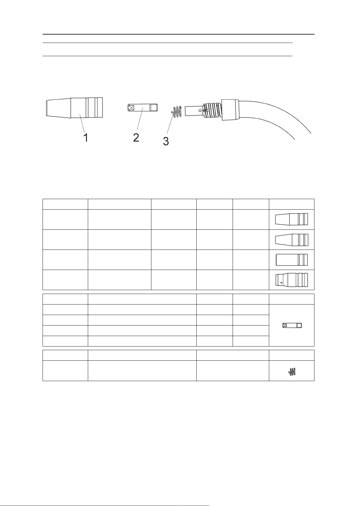
WEAR PARTS
WEAR PARTS
MXL 201
1. Gas nozzle 3. Nozzle spring
2. Contact tip M6 x 25
Ordering no. Denomination Notes Ø Length
0700 200 054 Gas nozzle Conical 12 mm 53 mm
0700 200 060 Gas nozzle Conical 9.5 mm 53 mm
0700 200 057 Gas nozzle Cylindrical 16 mm 53 mm
0700 200 105 Gas nozzle For self
6.5 mm 43.5 mm
shielding wire
Ordering no. Denomination Notes Ø
0700 200 063 Contact tip, M6 x 25 Cu 0.6 mm
0700 200 064 Contact tip, M6 x 25 Cu 0.8 mm
0700 200 065 Contact tip, M6 x 25 Cu 0.9 mm
0700 200 066 Contact tip, M6 x 25 Cu 1.0 mm
Ordering no. Denomination Notes
0700 200 078 Nozzle spring
Bold = Standard delivery
0463 633 001
- 21 -
© ESAB AB 2018
Page 22
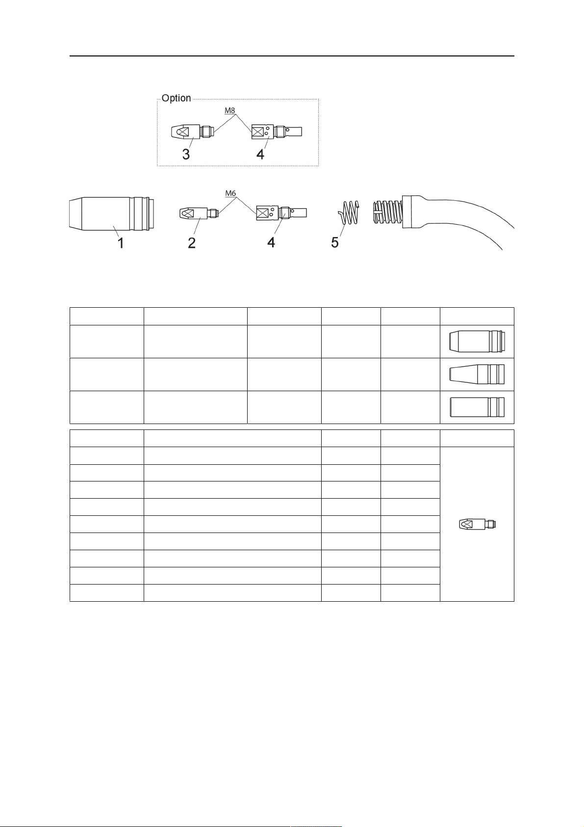
WEAR PARTS
MXL 271
1. Gas nozzle 4. Tip adaptor
2. Contact tip M6 x 28 5. Nozzle spring
3. Contact tip M8 x 30
Ordering no. Denomination Notes Ø Length
0700 200 055 Gas nozzle Conical 15 mm 56 mm
0700 200 061 Gas nozzle Conical 11 mm 56 mm
0700 200 058 Gas nozzle Cylindrical 20 mm 56 mm
Ordering no. Denomination Notes Ø
0700 200 068 Contact tip, M6 x 28 Cu 0.8 mm
0700 200 069 Contact tip, M6 x 28 Cu 0.9 mm
0700 200 070 Contact tip, M6 x 28 Cu 1.0 mm
0700 200 071 Contact tip, M6 x 28 Cu 1.2 mm
0700 200 081 Contact tip, M6 x 28 CuCrZr 0.8 mm
0700 200 083 Contact tip, M6 x 28 CuCrZr 1.0 mm
0700 200 084 Contact tip, M6 x 28 CuCrZr 1.2 mm
0700 025 273 Contact tip, M6 x 28 Alu Cu 1.0 mm
0700 025 274 Contact tip, M6 x 28 Alu Cu 1.2 mm
Bold = Standard delivery
0463 633 001
- 22 -
© ESAB AB 2018
Page 23
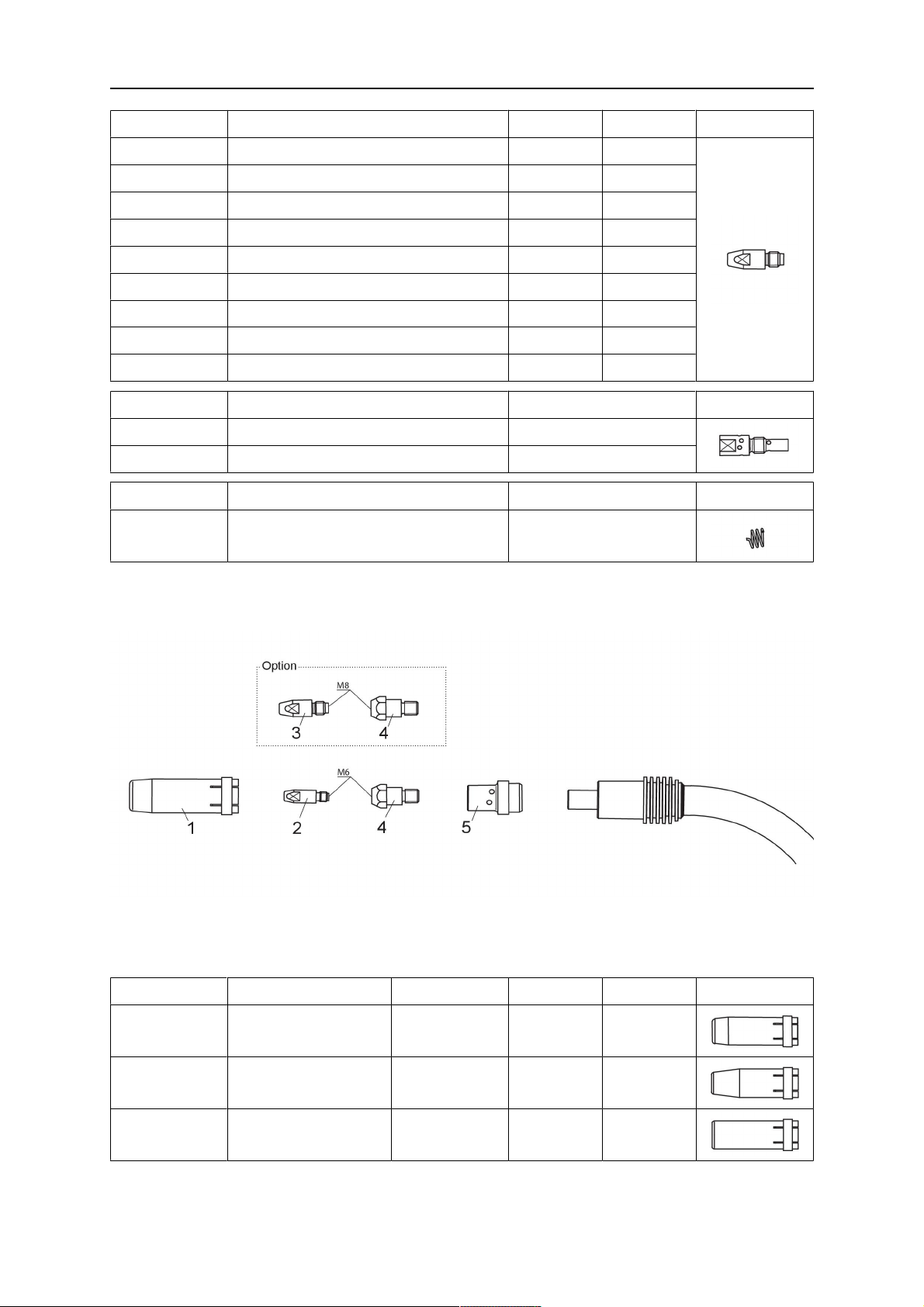
WEAR PARTS
Ordering no. Denomination Notes Ø
0700 025 275 Contact tip, M8 x 30 Cu 0.8 mm
0700 025 276 Contact tip, M8 x 30 Cu 1.0 mm
0700 025 277 Contact tip, M8 x 30 Cu 1.2 mm
0700 025 280 Contact tip, M8 x 30 CuCrZr 0.8 mm
0700 025 281 Contact tip, M8 x 30 CuCrZr 0.9 mm
0700 200 103 Contact tip, M8 x 30 CuCrZr 1.0 mm
0700 200 104 Contact tip, M8 x 30 CuCrZr 1.2 mm
0700 025 286 Contact tip, M8 x 30 Alu Cu 1.0 mm
0700 025 287 Contact tip, M8 x 30 Alu Cu 1.2 mm
Ordering no. Denomination Notes
0700 200 073 Tip adaptor M6 / L=35 mm
0700 025 289 Tip adaptor M8 / L=35 mm
Ordering no. Denomination Notes
0700 200 079 Nozzle spring
Bold = Standard delivery
MXL 341
1. Gas nozzle 4. Tip adaptor
2. Contact tip M6 x 28 5. Gas diffusor
3. Contact tip M8 x 30
Ordering no. Denomination Notes Ø Length
0700 200 056 Gas nozzle Conical 16 mm 83.5 mm
0700 200 062 Gas nozzle Conical
12 mm 83.5 mm
Only for M6
0700 200 059 Gas nozzle Cylindrical 20 mm 83.5 mm
Bold = Standard delivery
0463 633 001
- 23 -
© ESAB AB 2018
Page 24
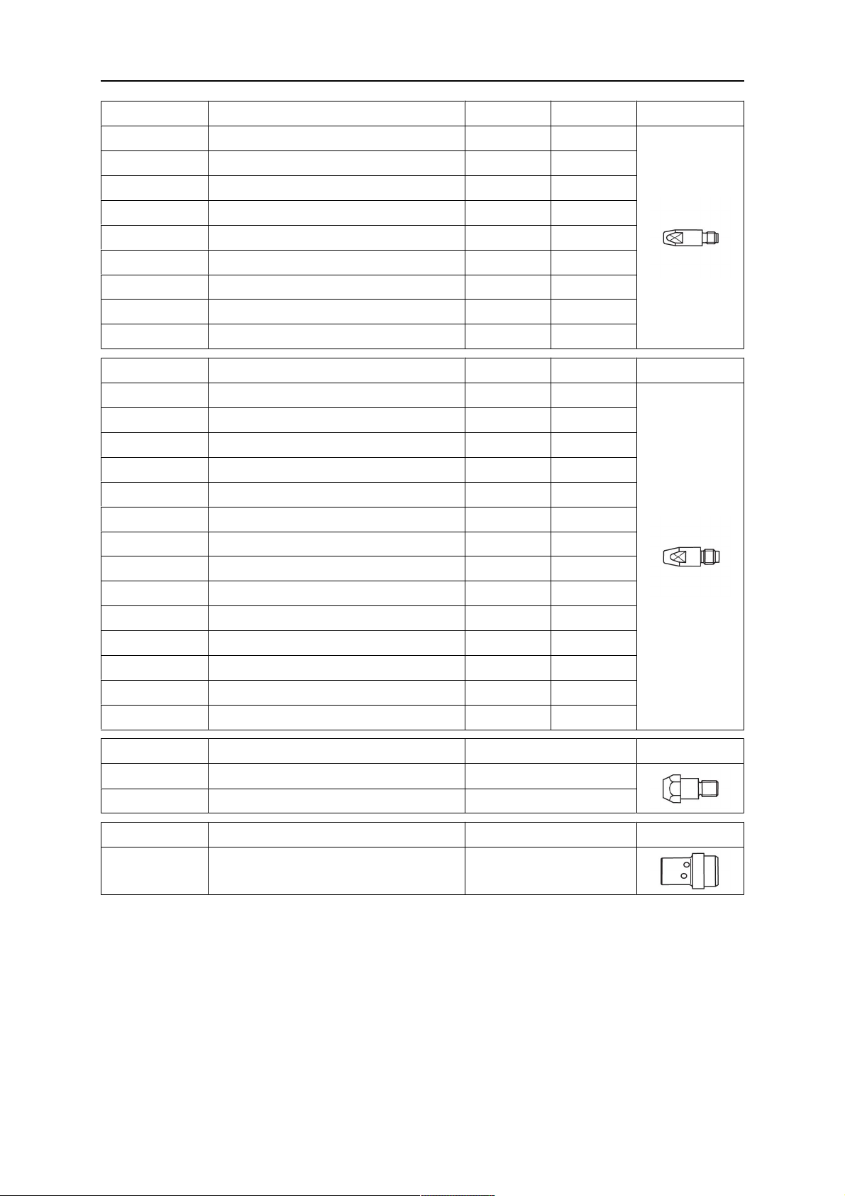
WEAR PARTS
Ordering no. Denomination Notes Ø
0700 200 068 Contact tip, M6 x 28 Cu 0.8 mm
0700 200 069 Contact tip, M6 x 28 Cu 0.9 mm
0700 200 070 Contact tip, M6 x 28 Cu 1.0 mm
0700 200 071 Contact tip, M6 x 28 Cu 1.2 mm
0700 200 081 Contact tip, M6 x 28 CuCrZr 0.8 mm
0700 200 083 Contact tip, M6 x 28 CuCrZr 1.0 mm
0700 200 084 Contact tip, M6 x 28 CuCrZr 1.2 mm
0700 025 273 Contact tip, M6 x 28 Alu Cu 1.0 mm
0700 025 274 Contact tip, M6 x 28 Alu Cu 1.2 mm
Ordering no. Denomination Notes Ø
0700 025 275 Contact tip, M8 x 30 Cu 0.8 mm
0700 025 276 Contact tip, M8 x 30 Cu 1.0 mm
0700 025 277 Contact tip, M8 x 30 Cu 1.2 mm
0700 025 278 Contact tip, M8 x 30 Cu 1.4 mm
0700 025 279 Contact tip, M8 x 30 Cu 1.6 mm
0700 025 280 Contact tip, M8 x 30 CuCrZr 0.8 mm
0700 025 281 Contact tip, M8 x 30 CuCrZr 0.9 mm
0700 200 103 Contact tip, M8 x 30 CuCrZr 1.0 mm
0700 200 104 Contact tip, M8 x 30 CuCrZr 1.2 mm
0700 025 284 Contact tip, M8 x 30 CuCrZr 1.4 mm
0700 025 285 Contact tip, M8 x 30 CuCrZr 1.6 mm
0700 025 286 Contact tip, M8 x 30 Alu Cu 1.0 mm
0700 025 287 Contact tip, M8 x 30 Alu Cu 1.2 mm
0700 025 288 Contact tip, M8 x 30 Alu Cu 1.6 mm
Ordering no. Denomination Notes
0700 200 074 Tip adaptor M6 / L=28 mm
0700 025 290 Tip adaptor M8 / L=28 mm
Ordering no. Denomination Notes
0700 200 080 Gas diffusor Black
Bold = Standard delivery
0463 633 001
- 24 -
© ESAB AB 2018
Page 25
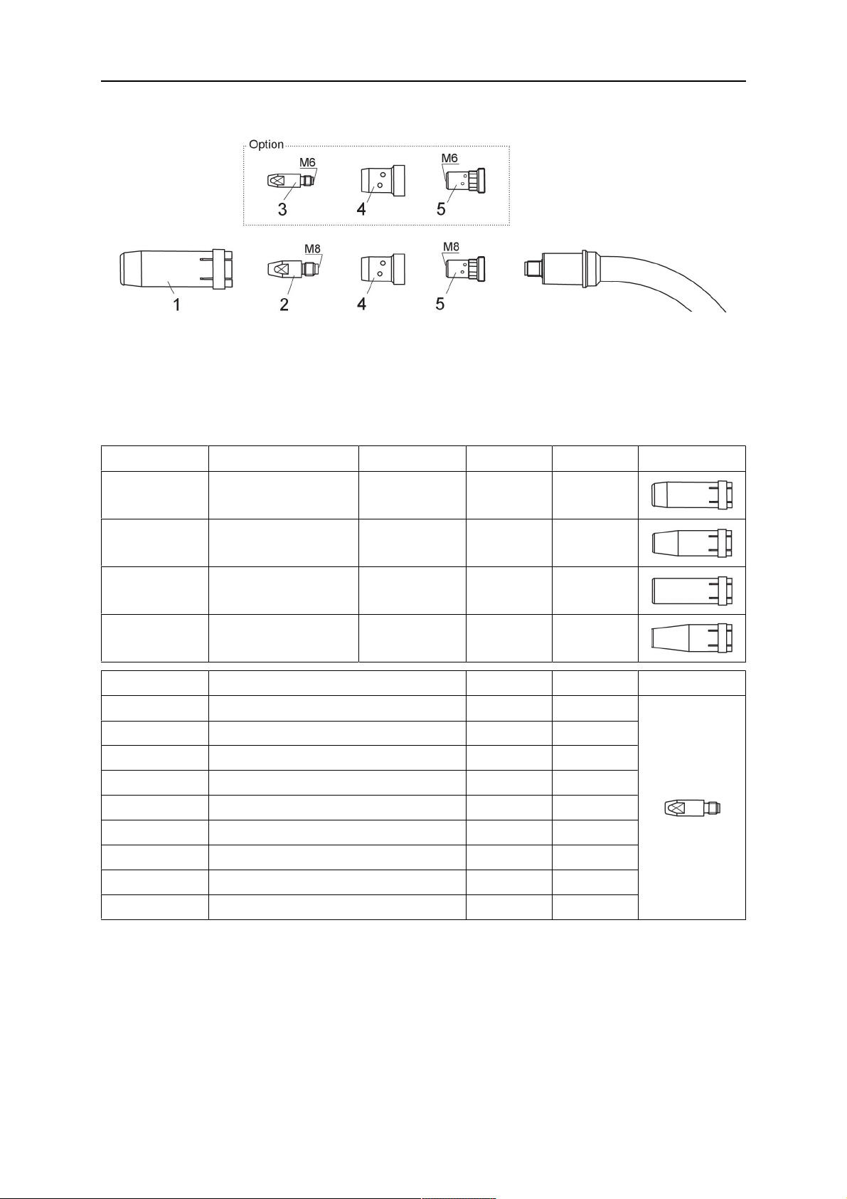
WEAR PARTS
MXL 411W / 511W
1. Gas nozzle 4. Gas diffusor
2. Contact tip M6 x 28 5. Tip adaptor
3. Contact tip M8 x 30
Ordering no. Denomination Notes Ø Length
0700 025 295 Gas nozzle Conical 16 mm 75.5 mm
0700 025 296 Gas nozzle Conical 14 mm 75.5 mm
0700 025 297 Gas nozzle Cylindrical 20 mm 75.5 mm
0700 025 298 Gas nozzle Conical
12 mm 75.5 mm
Only for M6
Ordering no. Denomination Notes Ø
0700 200 068 Contact tip, M6 x 28 Cu 0.8 mm
0700 200 069 Contact tip, M6 x 28 Cu 0.9 mm
0700 200 070 Contact tip, M6 x 28 Cu 1.0 mm
0700 200 071 Contact tip, M6 x 28 Cu 1.2 mm
0700 200 081 Contact tip, M6 x 28 CuCrZr 0.8 mm
0700 200 083 Contact tip, M6 x 28 CuCrZr 1.0 mm
0700 200 084 Contact tip, M6 x 28 CuCrZr 1.2 mm
0700 025 273 Contact tip, M6 x 28 Alu Cu 1.0 mm
0700 025 274 Contact tip, M6 x 28 Alu Cu 1.2 mm
Bold = Standard delivery
0463 633 001
- 25 -
© ESAB AB 2018
Page 26
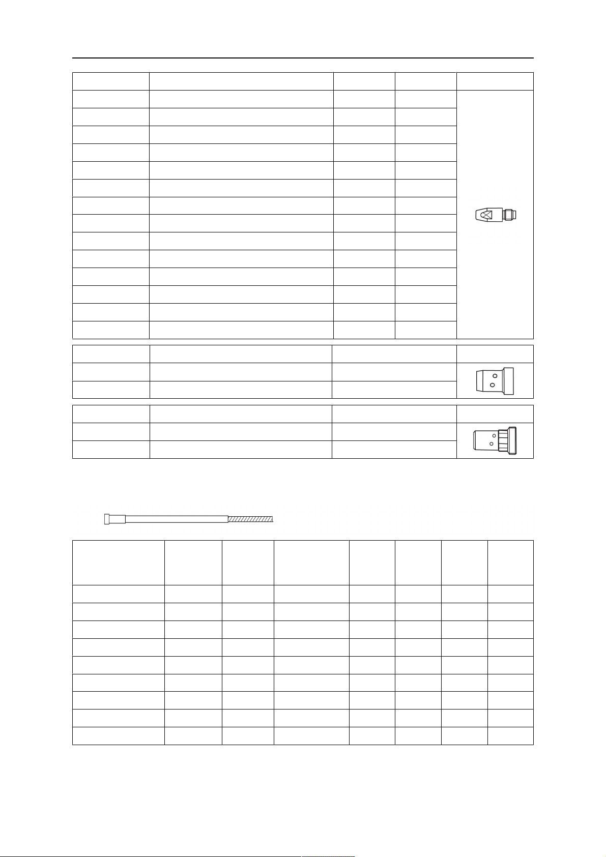
WEAR PARTS
Ordering no. Denomination Notes Ø
0700 025 275 Contact tip, M8 x 30 Cu 0.8 mm
0700 025 276 Contact tip, M8 x 30 Cu 1.0 mm
0700 025 277 Contact tip, M8 x 30 Cu 1.2 mm
0700 025 278 Contact tip, M8 x 30 Cu 1.4 mm
0700 025 279 Contact tip, M8 x 30 Cu 1.6 mm
0700 025 280 Contact tip, M8 x 30 CuCrZr 0.8 mm
0700 025 281 Contact tip, M8 x 30 CuCrZr 0.9 mm
0700 200 103 Contact tip, M8 x 30 CuCrZr 1.0 mm
0700 200 104 Contact tip, M8 x 30 CuCrZr 1.2 mm
0700 025 284 Contact tip, M8 x 30 CuCrZr 1.4 mm
0700 025 285 Contact tip, M8 x 30 CuCrZr 1.6 mm
0700 025 286 Contact tip, M8 x 30 Alu Cu 1.0 mm
0700 025 287 Contact tip, M8 x 30 Alu Cu 1.2 mm
0700 025 288 Contact tip, M8 x 30 Alu Cu 1.6 mm
Ordering no. Denomination Notes
0700 025 293 Gas diffusor Black
0700 025 294 Gas diffusor Ceramic
Ordering no. Denomination Notes
0700 025 291 Tip adaptor M8 / L=25 mm
0700 025 292 Tip adaptor M6 / L=25 mm
Bold = Standard delivery
Steel liner
Ordering no. Ø Length Notes MXL
201
MXL
271
MXL
341
0700 200 085 0.8 - 1.0 3.0 m Blue X X X X
0700 200 086 0.8 - 1.0 4.0 m Blue X X X X
0700 025 800 0.8 - 1.0 5.0 m Blue X X
0700 200 087 1.0 - 1.2 3.0 m Red X X X
MXL
411 /
511W
0700 200 088 1.0 - 1.2 4.0 m Red X X X
0700 025 801 1.0 - 1.2 5.0 m Red X X
0700 025 802 1.2 - 1.6 3.0 m Yellow X X
0700 025 803 1.2 - 1.6 4.0 m Yellow X X
0700 025 804 1.2 - 1.6 5.0 m Yellow X X
Bold = Standard delivery
0463 633 001
- 26 -
© ESAB AB 2018
Page 27
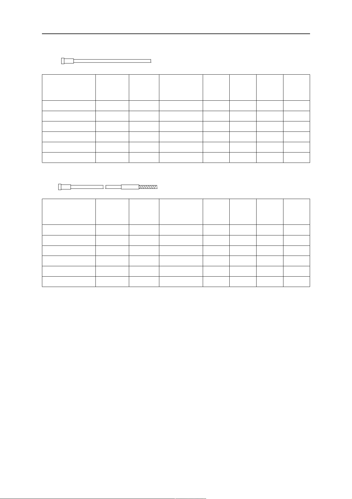
WEAR PARTS
PTFE liner
Ordering no. Ø Length Notes MXL
201
MXL
271
MXL
341
0700 200 091 1.0 - 1.2 3.0 Red X X X X
0700 200 092 1.0 - 1.2 4.0 Red X X X X
0700 025 812 1.0 - 1.2 5.0 Red X X
0700 025 813 1.2 - 1.6 3.0 Yellow X X
0700 025 814 1.2 - 1.6 4.0 Yellow X X
0700 025 815 1.2 - 1.6 5.0 Yellow X X
PA Liner with bronze front end
Ordering no. Ø Length Notes MXL
201
MXL
271
MXL
341
0700 025 816 0.8 - 1.0 3.0 Anthracite X X X X
0700 025 817 0.8 - 1.0 4.0 Anthracite X X X X
0700 025 818 0.8 - 1.0 5.0 Anthracite X X
MXL
411 /
511W
MXL
411 /
511W
0700 025 819 1.2 - 1.6 3.0 Anthracite X X
0700 025 820 1.2 - 1.6 4.0 Anthracite X X
0700 025 821 1.2 - 1.6 5.0 Anthracite X X
0463 633 001
- 27 -
© ESAB AB 2018
Page 28
ESAB AB, Lindholmsallén 9, Box 8004, 402 77 Gothenburg, Sweden, Phone +46 (0) 31 50 90 00
http://manuals.esab.com
For contact information visit esab.com
 Loading...