

ESAB Mig 4002cw, Mig 5002cw, Mig 4002c, Mig 5002c, Mig 6502cw Service Manual
...
0349 300 080 Valid for serial no.
740,743,741,744,742,745,801,802,803,804,806,805--xxx--xxxx
101229
Mig 4002cw, Mig 4002c
Mig 5002cw, Mig 5002c
Mig 6502cw, Mig 6502c
Origo
Servicemanual

-- 2 --
TOCe
READ THIS FIRST 4. . . . . . . . . . . . . . . . . . . . . . . . . . . . . . . . . . . . . . . . . . . . . . . . . . . . . . . . . . . . . . . . .
INTRODUCTION 4. . . . . . . . . . . . . . . . . . . . . . . . . . . . . . . . . . . . . . . . . . . . . . . . . . . . . . . . . . . . . . . . . . .
TECHNICAL DATA 5. . . . . . . . . . . . . . . . . . . . . . . . . . . . . . . . . . . . . . . . . . . . . . . . . . . . . . . . . . . . . . . . .
WIRING DIAGRAM 8. . . . . . . . . . . . . . . . . . . . . . . . . . . . . . . . . . . . . . . . . . . . . . . . . . . . . . . . . . . . . . . . .
Component description 8. . . . . . . . . . . . . . . . . . . . . . . . . . . . . . . . . . . . . . . . . . . . . . . . . . . . . . . . . .
OrigoTM Mig 4002c / 5002c / 6502c block diagram 9. . . . . . . . . . . . . . . . . . . . . . . . . . . . . . . . .
? 230V / 400--415V / 440--460V / 500V ? 18. . . . . . . . . . . . . . . . . . . . . . . . . . . . . . . . . . . . . . . . . . . .
Burndy 23 <--> Amphenol 19 19. . . . . . . . . . . . . . . . . . . . . . . . . . . . . . . . . . . . . . . . . . . . . . . . . . . .
DESCRIPTION OF OPERATION 20. . . . . . . . . . . . . . . . . . . . . . . . . . . . . . . . . . . . . . . . . . . . . . . . . . . . .
CB0 Control circuit board 20. . . . . . . . . . . . . . . . . . . . . . . . . . . . . . . . . . . . . . . . . . . . . . . . . . . . . . . .
CB0:1 Circuit board identity 20. . . . . . . . . . . . . . . . . . . . . . . . . . . . . . . . . . . . . . . . . . . . . . . . . . . . . . . .
CB0:2 Power supply 20. . . . . . . . . . . . . . . . . . . . . . . . . . . . . . . . . . . . . . . . . . . . . . . . . . . . . . . . . . . . . .
CB0:3 The CAN bus 21. . . . . . . . . . . . . . . . . . . . . . . . . . . . . . . . . . . . . . . . . . . . . . . . . . . . . . . . . . . . . .
Terminating resistors 22. . . . . . . . . . . . . . . . . . . . . . . . . . . . . . . . . . . . . . . . . . . . . . . . . . . . . . . . . . . . . .
CB0:4 Temperature monitoring 22. . . . . . . . . . . . . . . . . . . . . . . . . . . . . . . . . . . . . . . . . . . . . . . . . . . . .
CB0:5 Current sensor 23. . . . . . . . . . . . . . . . . . . . . . . . . . . . . . . . . . . . . . . . . . . . . . . . . . . . . . . . . . . . .
CB0:5.1 Calibrating the current sensor signal 24. . . . . . . . . . . . . . . . . . . . . . . . . . . . . . . . . . . . . . . . .
CB0:6 Arc voltage input Mig/Mag 25. . . . . . . . . . . . . . . . . . . . . . . . . . . . . . . . . . . . . . . . . . . . . . . . . . .
CB0:6.1 Calibration of the arc voltage feedback 26. . . . . . . . . . . . . . . . . . . . . . . . . . . . . . . . . . . . . .
CB0:7 Arc voltage input in MMA process 28. . . . . . . . . . . . . . . . . . . . . . . . . . . . . . . . . . . . . . . . . . . .
CB0 Components positions 29. . . . . . . . . . . . . . . . . . . . . . . . . . . . . . . . . . . . . . . . . . . . . . . . . . . . . . . .
ACH10 Driver/relays board 30. . . . . . . . . . . . . . . . . . . . . . . . . . . . . . . . . . . . . . . . . . . . . . . . . . . . . . .
ACH10:1 Circuit diagram 30. . . . . . . . . . . . . . . . . . . . . . . . . . . . . . . . . . . . . . . . . . . . . . . . . . . . . . . . . .
ACH10:2 Power supply 30. . . . . . . . . . . . . . . . . . . . . . . . . . . . . . . . . . . . . . . . . . . . . . . . . . . . . . . . . . . .
ACH10:3 PWM driver 31. . . . . . . . . . . . . . . . . . . . . . . . . . . . . . . . . . . . . . . . . . . . . . . . . . . . . . . . . . . . .
ACH10:4 Pre charging voltage sense 32. . . . . . . . . . . . . . . . . . . . . . . . . . . . . . . . . . . . . . . . . . . . . . .
ACH10:5 Mains contactor circuit, energy saving 33. . . . . . . . . . . . . . . . . . . . . . . . . . . . . . . . . . . . . .
ACH10:6 Cooling fan 33. . . . . . . . . . . . . . . . . . . . . . . . . . . . . . . . . . . . . . . . . . . . . . . . . . . . . . . . . . . . .
ACH10:7 Cooling liquid pump 34. . . . . . . . . . . . . . . . . . . . . . . . . . . . . . . . . . . . . . . . . . . . . . . . . . . . . .
ACH10:8 Flow guard 34. . . . . . . . . . . . . . . . . . . . . . . . . . . . . . . . . . . . . . . . . . . . . . . . . . . . . . . . . . . . . .
ACH10 Components positions 35. . . . . . . . . . . . . . . . . . . . . . . . . . . . . . . . . . . . . . . . . . . . . . . . . . . . .
PF20 Suppression circuit board 36. . . . . . . . . . . . . . . . . . . . . . . . . . . . . . . . . . . . . . . . . . . . . . . . . .
PF20:1 Circuit diagram 36. . . . . . . . . . . . . . . . . . . . . . . . . . . . . . . . . . . . . . . . . . . . . . . . . . . . . . . . . . . .
PF20:2 Components positions 36. . . . . . . . . . . . . . . . . . . . . . . . . . . . . . . . . . . . . . . . . . . . . . . . . . . . .
REMOTE CONTROLS 36. . . . . . . . . . . . . . . . . . . . . . . . . . . . . . . . . . . . . . . . . . . . . . . . . . . . . . . . . . . . . .
FAULT CODES 37. . . . . . . . . . . . . . . . . . . . . . . . . . . . . . . . . . . . . . . . . . . . . . . . . . . . . . . . . . . . . . . . . . . .
Fault log 37. . . . . . . . . . . . . . . . . . . . . . . . . . . . . . . . . . . . . . . . . . . . . . . . . . . . . . . . . . . . . . . . . . . . . . . .
Fault code description, power source 38. . . . . . . . . . . . . . . . . . . . . . . . . . . . . . . . . . . . . . . . . . . . . . . .
SERVICE INSTRUCTIONS 41. . . . . . . . . . . . . . . . . . . . . . . . . . . . . . . . . . . . . . . . . . . . . . . . . . . . . . . . . .
What is ESD? 41. . . . . . . . . . . . . . . . . . . . . . . . . . . . . . . . . . . . . . . . . . . . . . . . . . . . . . . . . . . . . . . . . . .
Service aid 42. . . . . . . . . . . . . . . . . . . . . . . . . . . . . . . . . . . . . . . . . . . . . . . . . . . . . . . . . . . . . . . . . . . . . .
ESAB Administration Tool (ESAT) 42. . . . . . . . . . . . . . . . . . . . . . . . . . . . . . . . . . . . . . . . . . . . . . . . . .
CAN supply service kit 42. . . . . . . . . . . . . . . . . . . . . . . . . . . . . . . . . . . . . . . . . . . . . . . . . . . . . . . . . . . .
Antistatic service kit 43. . . . . . . . . . . . . . . . . . . . . . . . . . . . . . . . . . . . . . . . . . . . . . . . . . . . . . . . . . . . . . .
Checking PWM signal 43. . . . . . . . . . . . . . . . . . . . . . . . . . . . . . . . . . . . . . . . . . . . . . . . . . . . . . . . . . . . .
Checking thermal cutout 46. . . . . . . . . . . . . . . . . . . . . . . . . . . . . . . . . . . . . . . . . . . . . . . . . . . . . . . . . . .
Checking Flow guard
(only machines with Flow Guard sensor) 47. . . . . . . . . . . . . . . . . . . . . . . . . . . . . . . . . . . . . . . . . . . . .
Checking pre charging circuit 48. . . . . . . . . . . . . . . . . . . . . . . . . . . . . . . . . . . . . . . . . . . . . . . . . . . . . .
Checking Fan Circuit 48. . . . . . . . . . . . . . . . . . . . . . . . . . . . . . . . . . . . . . . . . . . . . . . . . . . . . . . . . . . . . .
Checking liquid pump circuit 49. . . . . . . . . . . . . . . . . . . . . . . . . . . . . . . . . . . . . . . . . . . . . . . . . . . . . . .
Checking the LED Indicators on board CB0 50. . . . . . . . . . . . . . . . . . . . . . . . . . . . . . . . . . . . . . . . . .
Checking chopper block V0 51. . . . . . . . . . . . . . . . . . . . . . . . . . . . . . . . . . . . . . . . . . . . . . . . . . . . . . . .
Overview test 53. . . . . . . . . . . . . . . . . . . . . . . . . . . . . . . . . . . . . . . . . . . . . . . . . . . . . . . . . . . . . . . . . . . .
Rectifier test 53. . . . . . . . . . . . . . . . . . . . . . . . . . . . . . . . . . . . . . . . . . . . . . . . . . . . . . . . . . . . . . . . . . . . .
Checking of output stage 54. . . . . . . . . . . . . . . . . . . . . . . . . . . . . . . . . . . . . . . . . . . . . . . . . . . . . . . . . .
Replacing of damaged transistors 55. . . . . . . . . . . . . . . . . . . . . . . . . . . . . . . . . . . . . . . . . . . . . . . . . .
High current aluminum leads maintenance 55. . . . . . . . . . . . . . . . . . . . . . . . . . . . . . . . . . . . . . . .

-- 3 --
TOCe
INSTRUCTIONS 56. . . . . . . . . . . . . . . . . . . . . . . . . . . . . . . . . . . . . . . . . . . . . . . . . . . . . . . . . . . . . . . . . . .
SAFETY 56. . . . . . . . . . . . . . . . . . . . . . . . . . . . . . . . . . . . . . . . . . . . . . . . . . . . . . . . . . . . . . . . . . . . . . . . . .
INSTALLATION 57. . . . . . . . . . . . . . . . . . . . . . . . . . . . . . . . . . . . . . . . . . . . . . . . . . . . . . . . . . . . . . . . . . . .
Placing 57. . . . . . . . . . . . . . . . . . . . . . . . . . . . . . . . . . . . . . . . . . . . . . . . . . . . . . . . . . . . . . . . . . . . . . . . .
Assembly of components 58. . . . . . . . . . . . . . . . . . . . . . . . . . . . . . . . . . . . . . . . . . . . . . . . . . . . . . . .
Mains power supply 59. . . . . . . . . . . . . . . . . . . . . . . . . . . . . . . . . . . . . . . . . . . . . . . . . . . . . . . . . . . . .
OPERATION 60. . . . . . . . . . . . . . . . . . . . . . . . . . . . . . . . . . . . . . . . . . . . . . . . . . . . . . . . . . . . . . . . . . . . . . .
Connections and control devices 60. . . . . . . . . . . . . . . . . . . . . . . . . . . . . . . . . . . . . . . . . . . . . . . . .
Overheating protection 60. . . . . . . . . . . . . . . . . . . . . . . . . . . . . . . . . . . . . . . . . . . . . . . . . . . . . . . . . .
Water connection 61. . . . . . . . . . . . . . . . . . . . . . . . . . . . . . . . . . . . . . . . . . . . . . . . . . . . . . . . . . . . . . .
Water flow guard 61. . . . . . . . . . . . . . . . . . . . . . . . . . . . . . . . . . . . . . . . . . . . . . . . . . . . . . . . . . . . . . . .
MAINTENANCE 61. . . . . . . . . . . . . . . . . . . . . . . . . . . . . . . . . . . . . . . . . . . . . . . . . . . . . . . . . . . . . . . . . . . .
Inspection and cleaning 61. . . . . . . . . . . . . . . . . . . . . . . . . . . . . . . . . . . . . . . . . . . . . . . . . . . . . . . . .
Topping up the coolant 61. . . . . . . . . . . . . . . . . . . . . . . . . . . . . . . . . . . . . . . . . . . . . . . . . . . . . . . . . .
FAULT TRACING 62. . . . . . . . . . . . . . . . . . . . . . . . . . . . . . . . . . . . . . . . . . . . . . . . . . . . . . . . . . . . . . . . . .
ORDERING OF SPARE PARTS 62. . . . . . . . . . . . . . . . . . . . . . . . . . . . . . . . . . . . . . . . . . . . . . . . . . . . . .
NOTES 63. . . . . . . . . . . . . . . . . . . . . . . . . . . . . . . . . . . . . . . . . . . . . . . . . . . . . . . . . . . . . . . . . . . . . . . . . . .

-- 4 --
1sxx02cw
READ THIS FIRST
Maintenance and repair work should be performed by an experienced person, and
electrical work only by a trained electrician. Use only recommended replacement parts.
This service manual is intended for use by technicians with electrical/electronic training for
help in connection with fault--tracing and repair.
Use the wiring diagram as a form of index for the description of operation. The circuit
board is divided into numbered blocks, which are described individually in more detail in
the description of operation. All component names in the wiring diagram are listed in the
component description.
This manual contains details of all design changes that have been made up to and
including December 2010.
The OrigoTMMig 4002cw, Mig 4002c, Mig 5002cw, Mig 5002c, Mig 6502cw, Mig 6502c
are designed and tested in accordance with European standard EN 60974--1 and EN
60974--10.
On completion of service or repair work, it is the responsibility of the person(s) etc.
performing the work to ensure that the product does not depart from the requirements
of the above standard.
WARNING
Many parts of the power unit are at mains voltage.
INTRODUCTION
The OrigoTMMig 4002cw, Mig 5002cw, Mig 6502cw are MIG/MAG welding power
sources, which can also be used for MMA welding.
There are two variants of the power sources:
S OrigoTMMig xx02c without cooling unit
S OrigoTMMig xx02cw with cooling unit
The power sources are intended for use with the AristoTMFeed 3004 or Aristo
TM
Feed 4804 wire feed units.
All the settings are made from the wire feed unit.
-- 5 --
1sxx02cw
TECHNICAL DATA
OrigoTMMig 4002cw
Mains voltage 230/400--415/500 V 3∼ 50 Hz
230/440--460 V 3∼ 60 Hz
Permissible load at
60 % duty cycle
100% duty cycle
Mig/Mag: 400 A / 34 V; MMA: 400 A / 36 V
Mig/Mag: 310 A / 30 V; MMA: 310 A / 33 V
Setting range (DC)
MIG/MAG
MMA
Mig/Mag: 16A / 8V--400 A / 34 V
MMA: 16A / 8V--400 A / 36 V
Open circuit voltage Mig/Mag: 62V; MMA: 68V
Open circuit power
with cooling unit
in energy saving mode
(15 min after last welding)
500 W
700 W
60W
Power factor at maximum current 0,88
Efficiency at maximum current 70 %
Control voltage 42 V, 50/60 Hz
Dimensions lxwxh 830 x 640 x 835 mm
Weight
with cooling unit
149 kg
163 kg
Operating temperature --10 to +40˚C
Enclosure class IP 23
Application classification
OrigoTMMig 5002cw
Mains voltage 230/400--415/500 V 3∼ 50 Hz
230/440--460 V 3∼ 60 Hz
Permissible load at
60 % duty cycle
100% duty cycle
Mig/Mag: 500 A / 39 V; MMA: 500 A / 40 V
Mig/Mag: 400 A / 34 V; MMA: 400 A / 36 V
Setting range (DC)
MIG/MAG
MMA
Mig/Mag: 16A / 8V--500 A / 39 V
MMA: 16A / 8V--500 A / 40 V
Open circuit voltage Mig/Mag: 62V; MMA: 68V
Open circuit power
with cooling unit
in energy saving mode
(15 min after last welding)
550 W
750 W
60W
Power factor at maximum current 0,90
Efficiency at maximum current 72 %
Control voltage 42 V, 50/60 Hz
Dimensions lxwxh 830 x 640 x 835 mm
Weight
with cooling unit
185 kg
199 kg
Operating temperature --10 to +40˚C

-- 6 --
1sxx02cw
Enclosure class IP 23
Application classification
OrigoTMMig 6502cw
Mains voltage 230/400--415/500 V 3∼ 50 Hz
230/440--460 V 3∼ 60 Hz
Permissible load at
60 % duty cycle
100% duty cycle
Mig/Mag: 650 A / 44 V; MMA: 650 A / 44 V
Mig/Mag: 500 A / 39 V; MMA: 500 A / 40 V
Setting range (DC)
MIG/MAG
MMA
Mig/Mag: 16A / 8V--650 A / 44 V
MMA: 16A / 8V--650 A / 44 V
Open circuit voltage Mig/Mag: 62V; MMA: 68V
Open circuit power
with cooling unit
in energy saving mode
(15 min after last welding)
670 W
870 W
60W
Power factor at maximum current 0,90
Efficiency at maximum current 76 %
Control voltage 42 V, 50/60 Hz
Dimensions lxwxh 830 x 640 x 835 mm
Weight
with cooling unit
222 kg
236 kg
Operating temperature --10 to +40˚C
Enclosure class IP 23
Application classification
Cooling unit
Cooling power 2500 W at40˚C temp. difference and flow
1,5l/min
Coolant 50 % water / 50% glycol
Coolant quantity 5,5 l
Maximum water flow 2,0 l/min
Duty cycle
The duty cycle refers to the time as a percentage of a ten--minute period that you can weld at a certain load without overloading.
Enclosure class
The IP code indicates the enclosure class, i. e. the degree of protection against penetration by solid
objects or water. Equipment marked IP 23 is designed for indoor and outdoor use.
Application class
The symbol indicates that the power source is designed for use in areas with increased
electrical hazard.

-- 7 --
1sxx02cw
This page is left blank intentionally.
-- 8 --
1sxx02cw
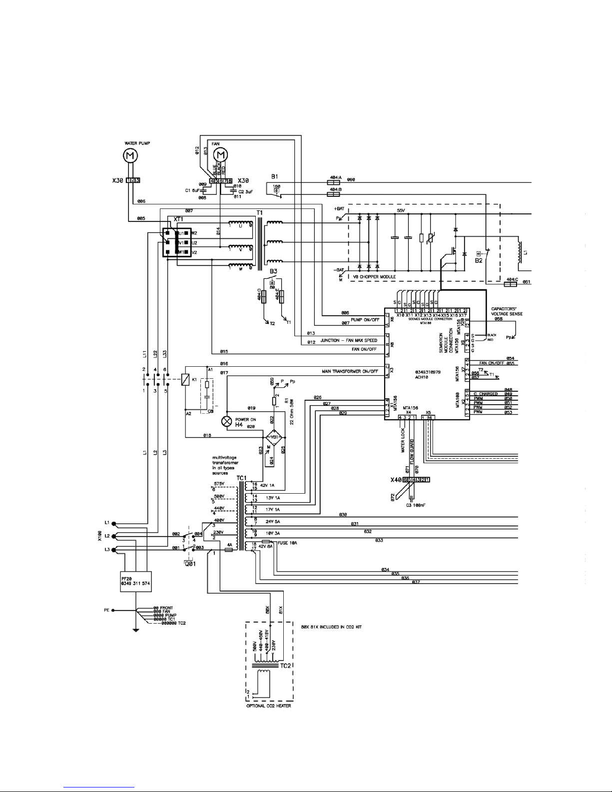
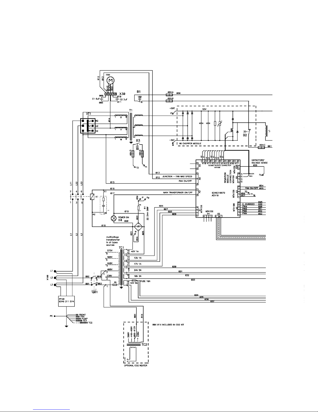
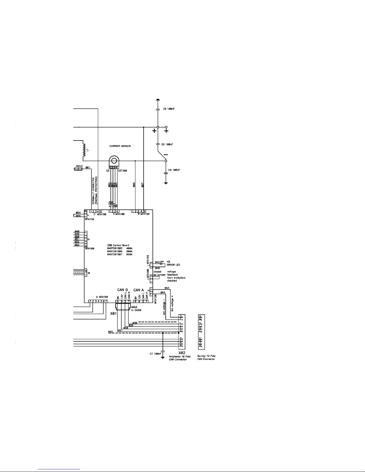
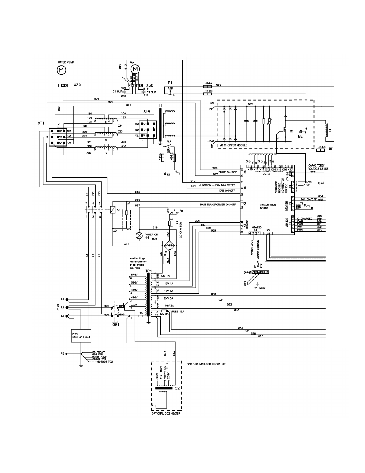
WIRING DIAGRAM
WARNING !
STATIC ELECTRICITY can damage circuit
boards and electronic components.
SSSS Observe precautions for handling electrostatic
sensitive devices.
SSSS Use proper static--proof bags and boxes.
ESD
Component description
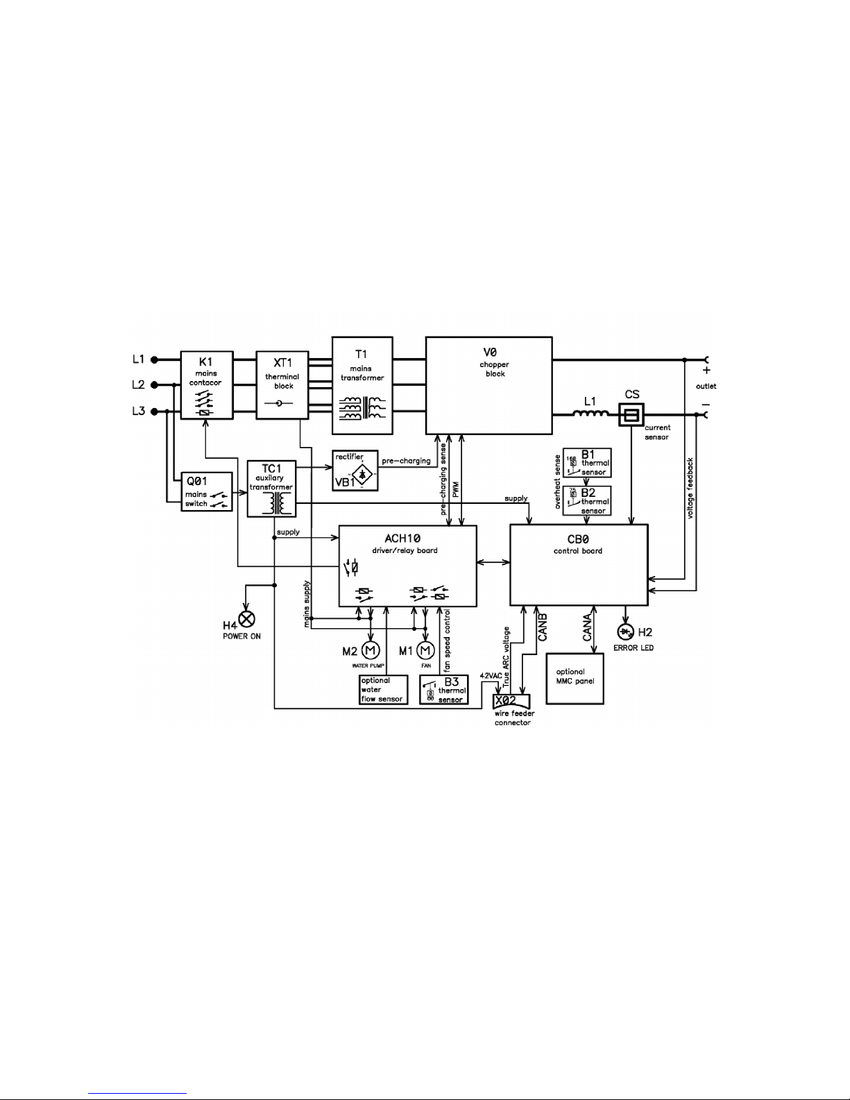
XT1 9 pole terminal block
PF20 Suppression circuit board
Q01 Main ON/OFF switch
K1 Main contactor
M1 Fan 230V 50Hz
M2 Pump motor, 230V 50Hz 0.2kW. Only machines with water cooler
C1 Capacitor, 6uF 250V, for reducing the speed of fan motor M1
C2 Capacitor, 3uF 400V. Start and run capacitor for fan motor M1
C3 -- C7 Suppression capacitors, 0,1uF 250V
C8 Snubber for K1 coil
H2 Orange indicating lamp, Error,overheating
H4 White indicating lamp, power supply ON
T1 Main transformer
TC1 Control power transformer
TC2 Transformer for CO2 heater. (an accessory, see an accessories listed in
user manual)
VB1 Rectifier
B1 Thermal switch. Protects the main transformer against excessive
temperature
B2 Thermal switch. Protects the chopper block against excessive temperature
B3 Thermal switch. Controls the speed of fan motor M1
CS Current sensor
R1 Resistor (pre--charging)
L1 Inductor
CB0 Control circuit board
-- 9 --
1sxx02cw
ACH10 Driver/relays circuit board
V0 Chopper module
X02 Connector, r Amphenol 10 pole or Burndy 12 pole (obsolete). For connection
to/from the wire feed unit
OrigoTMMig 4002c / 5002c / 6502c block diagram
-- 10 --
1sxx02cw
Mig 4002cw, 5002cw, 6502cw, 400 -- 415 V

-- 11 --
1sxx02cw
Mig 4002cw, 5002cw, 6502cw, 400 -- 415 V
-- 12 --
1sxx02cw
Mig 4002c, 5002c, 6502c, 400 -- 415 V
-- 13 --
1sxx02cw
Mig 4002c, 5002c, 6502c, 400 -- 415 V
-- 14 --
1sxx02cw
Mig 4002cw, 5002cw, 6502cw, 230 -- 500 V

-- 15 --
1sxx02cw
Mig 4002cw, 5002cw, 6502cw, 230 -- 500 V

-- 16 --
1sxx02cw
Mig 4002c, 5002c, 6502c, 230 -- 500 V

-- 17 --
1sxx02cw
Mig 4002c, 5002c, 6502c, 230 -- 500 V

-- 18 --
1sxx02cw
? 230V / 400--415V / 440--460V / 500V ?

-- 19 --
1sxx02cw
Burndy 23 <--> Amphenol 19
Burndy 23 Amphenol 19 Signals
A A 42V
B B 42V
C
D D 12V
E E 0V
F F Start contact
G G Artificial ground
H H Arc voltage
J J +15VB
K K Ref
L L 0VB
M
N
P
R
S
T T Data display
U U Clock display
V V Load display
W M Crater fill
X R Water connection monitoring
Y S Water connection monitoring
Z
-- 20 --
1sxx02cw
DESCRIPTION OF OPERATION
CB0 Control circuit board
The processor on the control board monitors and controls the various functions of the power
source. It obtains information on welding data and welding processes from the welding data
board in the MMC control panel.
CB0:1 Circuit board identity
The control board has a machine ID, a hardware ID and a unit type number. To
read this you need the ESAT service kit. The machine ID defines which type of
power source the board is intended for. The hardware ID shows design and type of
circuit board. The unit type is used for identification on the CAN bus.
The ID numbers of the machines :
S OrigoTMMig 4002c/cw: 38
S OrigoTMMig 5002c/cw: 39
S OrigoTMMig 6502c/cw: 40
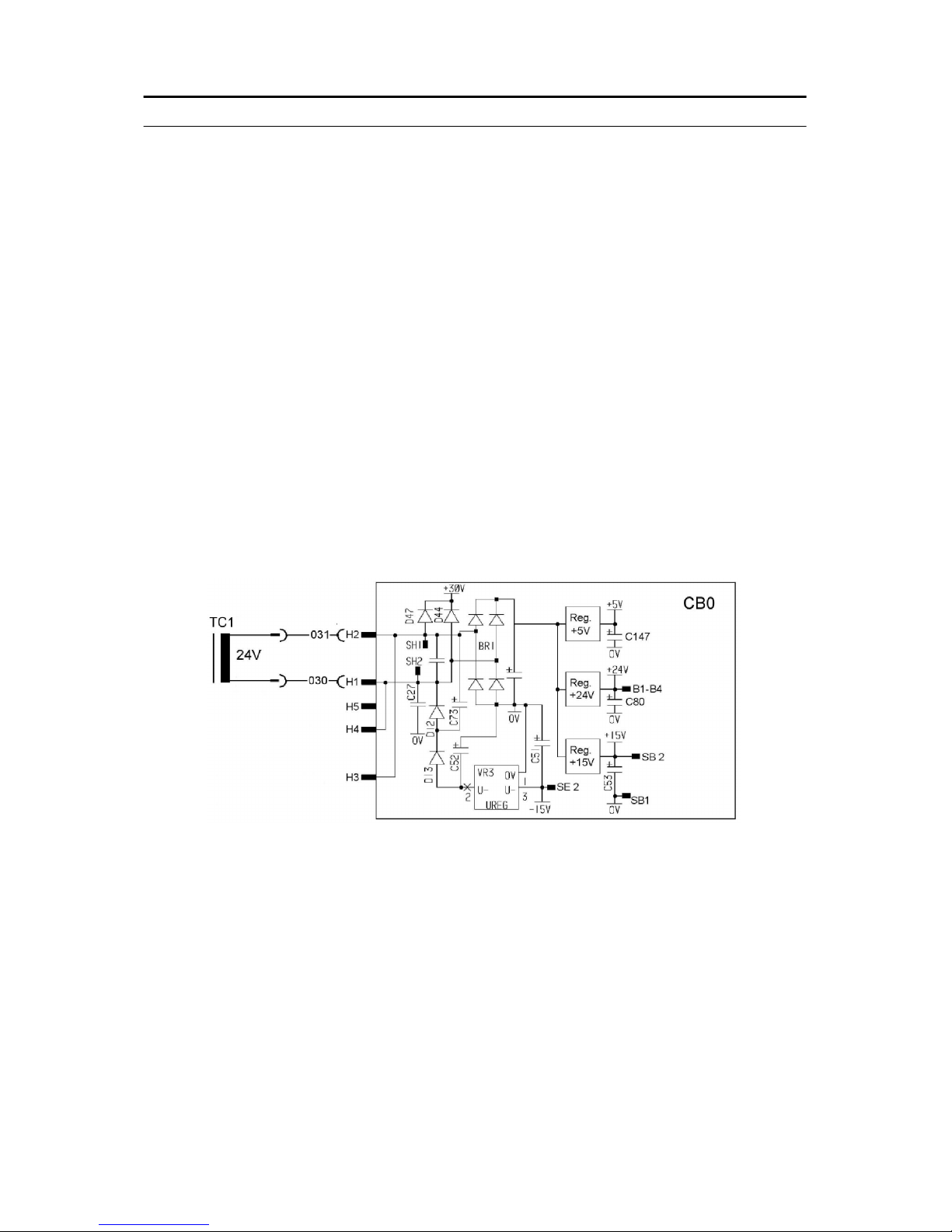
CB0:2 Power supply
+24 V Power supply to relay board CB0
+15 V Internal power supply on CB0
--15 V Internal power supply on CB0
+5 V Internal power supply on CB0
 Loading...