

ESAB GMH Instruction Manual

GMH
Bruksanvisning
Brugsanvisning
Bruksanvisning
Käyttöohjeet
Instruction manual
Betriebsanweisung
Manuel d’instructions
Gebruiksaanwijzing
Instrucciones de uso
Istruzioni per l’uso
Manual de instruções
使用说明书
Valid for serial no. 936--xxx--xxxx, 049--xxx--xxxx0460 671 160 2012--04--16

SVENSKA 4..............................................
DANSK 24................................................
NORSK 44................................................
SUOMI 64................................................
ENGLISH 84..............................................
DEUTSCH 104.............................................
FRANÇAIS 124.............................................
NEDERLANDS 144.........................................
ESPAÑOL 164..............................................
ITALIANO 184..............................................
PORTUGUÊS 204..........................................
中文 224...................................................
Rätt till ändring av specifikationer utan avisering förbehålles.
Ret til ændring af specifikationer uden varsel forbeholdes.
Rett til å endre spesifikasjoner uten varsel forbeholdes.
Oikeudet muutoksiin pidätetään.
Rights reserved to alter specifications without notice.
Änderungen vorbehalten.
Sous réserve de modifications sans avis préalable.
Recht op wijzigingen zonder voorafgaande mededeling voorbehouden.
Reservado el derecho de cambiar las especificaciones sin previo aviso.
Ci riserviamo il diritto di variare le specifiche senza preavviso.
Reservamo-nos o direito de alterar as especificações sem aviso prévio.
保留变更技术规范的权利,恕不另行通知。
-2-

DECLARATION OF CONFORMITY
according to the Low Voltage Directive 2006/95/EC, according to the EMC Directive 2004/108/EC
FÖRSÄKRAN OM ÖVERENSSTÄM MELSE
enligt Lågspänningsdirektivet 2006/95/EG, enligt EMC--Direktivet 2004/108/EG
Type of equipment Materialslag
Control box for joint--tracking
Brand name or trade mark Fabrikatnamn eller varumärke
ESAB
Type designation etc. Typbeteckning etc.
GMH, from serial number 936 xxx xxxx (2009 w.36)
GMH is designed to be used with ESAB welding equipment
Manufacturer or his authorised representative established within the EEA
Name, address, telephone No, telefax No: Tillverkarens namn, adress, telefon, telefax:
ESAB AB, Welding Equipment
Esabvägen, SE--695 81 LAXÅ, Sweden
Phone: +46 584 81 000, Fax: +46 584 411 924
The following harmonised standard in force within the EEA has been used in the design:
Följande harmoniserande standarder har använts i konstruktionen:
EN 60974 --1, Arc welding equipment – Part 1: Welding power sources, in relevant parts
EN 60974--10, Arc welding equipment – Part 10: Electromagnetic compatibility (EMC) requirements
Additional information: / Tilläggsinformation: Restrictive use, this Control Box is use with equipment of Class A, intended
for use in locations other than residential
By signing this document, the undersigned declares as manufacturer, or the manufacturer’s authorised
repr e se ntative established within the EEA, that the equipment in question complies with the safety re quirements
stated above.
Genom att underteckna detta dokument försäkrar undertecknad såsom tillverkare, eller tillverkarens representant inom
EES, att angiven materiel uppfyller säkerhetskraven angivna ovan.
Date / Datum
Laxå 2010--02--03
Signature / Underskrift Position / Befattning
Global Director
Equipment and Automation
Kent Eimbrodt
Clarification
3

ENGLISH
1SAFETY 85...........................................................
2 INTRODUCTION 87...................................................
2.1 General 87..................................................................
2.2 Variants 87..................................................................
2.3 Technical data 88............................................................
2.4 Main parts 89................................................................
3 INSTALLATION 91....................................................
3.1 General 91..................................................................
3.2 Installation and connection 91..................................................
3.3 Tuning the sensor finger 91....................................................
3.4 Tuning the inductive sensor 91.................................................
4 OPERATION 92.......................................................
4.1 General 92..................................................................
4.2 Joint--tracking unit with control panel 92.........................................
4.3 Joint--tracking unit -- rear section 94.............................................
4.4 Portable control box 95.......................................................
4.5 Joint--tracking 97.............................................................
4.6 Positioning for welding start 100.................................................
4.7 Positioning for welding start (with inductive joint--tracking) 101.......................
5 MAINTENANCE 102....................................................
5.1 General 102..................................................................
5.2 Wear parts 102...............................................................
6 ORDERING OF SPARE PARTS 102......................................
7 ACCESSORIES 103....................................................
DIAGRAM 244............................................................
DIMENSION DRAWING 247................................................
SPARE PARTS LIST 251...................................................
TOCe
-- 8 4 --

GB
1SAFETY
NOTE! The unit is tested by ESAB in a general purpose operation.
Responsibility for the safety and function of the final operation lies with the Integra tor.
Users of ESAB welding equipment have the ultimate responsibility for ensuring that anyone who
works on or near the equipment observes all the relevant safety precautions. Safety precautions
must meet the requirements that apply to this type of welding equipment. The following recommendations should be observed in addition to the standard regulations that apply to the workplace.
All work must be carried out by trained personnel well--acquainted with the operation of the welding
equipment. Incorrect operation of the equipment may lead to hazardous situations which can result
in injury to the operator and damage to the equipment.
1. Anyone who uses the welding equipment must be familiar with:
S its operation
S location of emergency stops
S its function
S relevant safety precautions
S welding
2. The operator must ensure that:
S no unauthorised person is stationed within the working area of the equipment when it is
started up.
S no--one is unprotected when the arc is struck
3. The workplace must:
S be suitable for the purpose
S be free from draughts
4. Personal safety equipment
S Always wear recommended personal safety equipment, such as safety glasses, flame--proof
clothing, safety gloves.
S Do not wear loose--fitting items, such as scarves, bracelets, rings, etc., which could become
trapped or cause burns.
5. General precautions
S Make sure the return cable is connected securely.
S Work on high voltage equipment may only be carried out by a qualified electrician.
S Appropriate fire extinquishing equipment must be clearly marked and close at hand.
S Lubrication and maintenance must not be carried out on the equipment during operation.
SafGB
-- 8 5 --

GB
WARNING
ARC WELDING AND CUTTING CAN BE INJURIOUS TO YOURSELF AND OTHERS. TAKE PRECAUTIONS WHEN WELDING. ASK FOR YOUR EMPLOYER’S SAFETY PRACTICES WHICH SHOULD BE
BASED ON MANUFACTURERS’ HAZARD DATA.
ELECTRIC SHOCK -- Can kill
S Install and earth the welding unit in accordance with applicable standards.
S Do not touch live electrical parts or electrodes with bare skin, wet gloves or wet clothing.
S Insulate yourself from earth and the workpiece.
S Ensure your working stance is safe.
FUMES AND GASES -- Can b e dangerous to health
S Keep your head out of the fumes.
S Use ventilation, extraction at the arc, or both, to take fumes and gases away from your breathing zone
and the general area.
ARC RAYS -- Can injure eyes and burn skin.
S Protect your eyes and body. Use the correct welding screen and filter lens and wear protective
clothing.
S Protect bystanders with suitable screens or curtains.
FIRE HAZARD
S Sparks (spatter) can cause fire. Make sure therefore that there are no inflammable materials nearby.
NOISE -- Excessive noise can damage hearing
S Protect your ears. Use earmuffs or other hearing protection.
S Warn bystanders of the risk.
MALFUNCTION -- Call for expert assistance in the event of malfunction.
READ AND UNDERSTAND THE INSTRUCTION MANUAL BEFORE INSTALLING OR OPERATING.
PROTECT YOURSELF AND OTHERS!
SafGB
-- 8 6 --
GB
2 INTRODUCTION
2.1 General
GMH is joint--tracking equipment for the positioning and joint--tracking of automatic
welding equipment in all types of joint that arise where the sensor finger has a
guiding edge to follow. The equipment is adapted to ESAB’s standard servo slides
and control one or two servo motors simultaneously.
The system is available in several variants, see below.
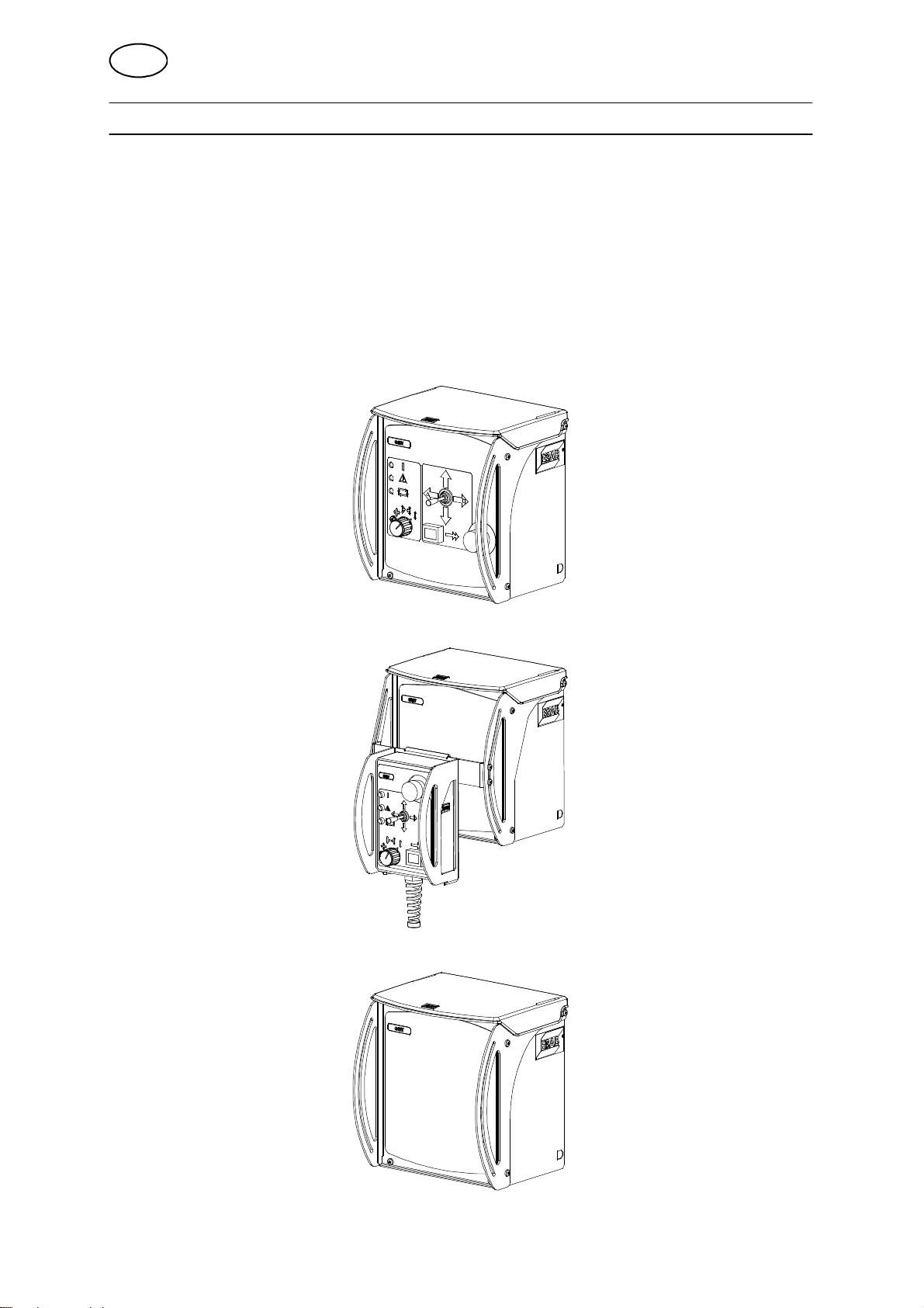
2.2 Variants
S Joint--tracking unit with control panel.
S Joint--tracking unit with portable control box.
S Built--in component for columns and booms.
hga1d1ea
-- 8 7 --
GB
2.3 Technical data
GMH
Supply voltage 42V AC, 50--60 Hz
Current output 450 V A
Ambient temperature -- 1 5 C--+45 C
Relative atmospheric humidity Max. 98%
Max. motor current 6A 100%
Enclosure class IP 23
Current limits 15 A (hardware current limit)
Power supply fusing 10 A slow
Motor regulator, type Switched four quadrant reg.
Rotor voltage 40 V DC
Field voltage, separate magnetised motor 60 V DC
Weights:
Joint--tracking unit:
Portable control box:
Sensor and slide cross with bracket:
Guide finger:
Working range sensor, radially 360 4mm
Enclosure class
The IP code indicates the enclosure class, i. e. the degree of protection against penetration by solid
objects or water. Equipment marked IP 23 is designed for indoor and outdoor use.
6,2 kg
2,7 kg (complete with 4m cable and protection)
2.2 kg
0.6 kg
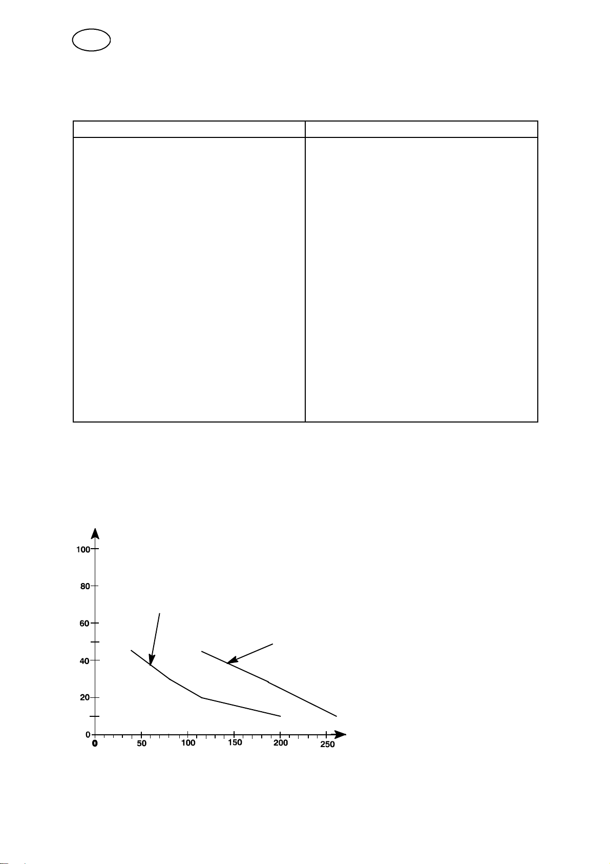
Working range and setting speed, see the figure below and the technical description
in the operating instructions for A6 Slide.
Angle deviation deg
Normal ratio
Inverted ratio
Welding speed cm/min
Diagram of the weld joint’s maximum angle deviation in relation to the set welding
speed.
hga1d1ea
-- 8 8 --

GB
2.4 Main parts
1. Joint--tracking unit (with or without control panel)
2. Portable control box
3. Sensor
4. Slide cross for sensor
5. Guide finger
6. Control cable (2 m)
7. Motor cable (see Accessories)
NB!
The portable control box (2) and the control cable (6), in accordance with the above,
are discontinued for certain columns and booms and are replaced by product
specific parts.
For more information, see the chapter ”Operation”, on page 92.
hga1d1ea
-- 8 9 --
GB
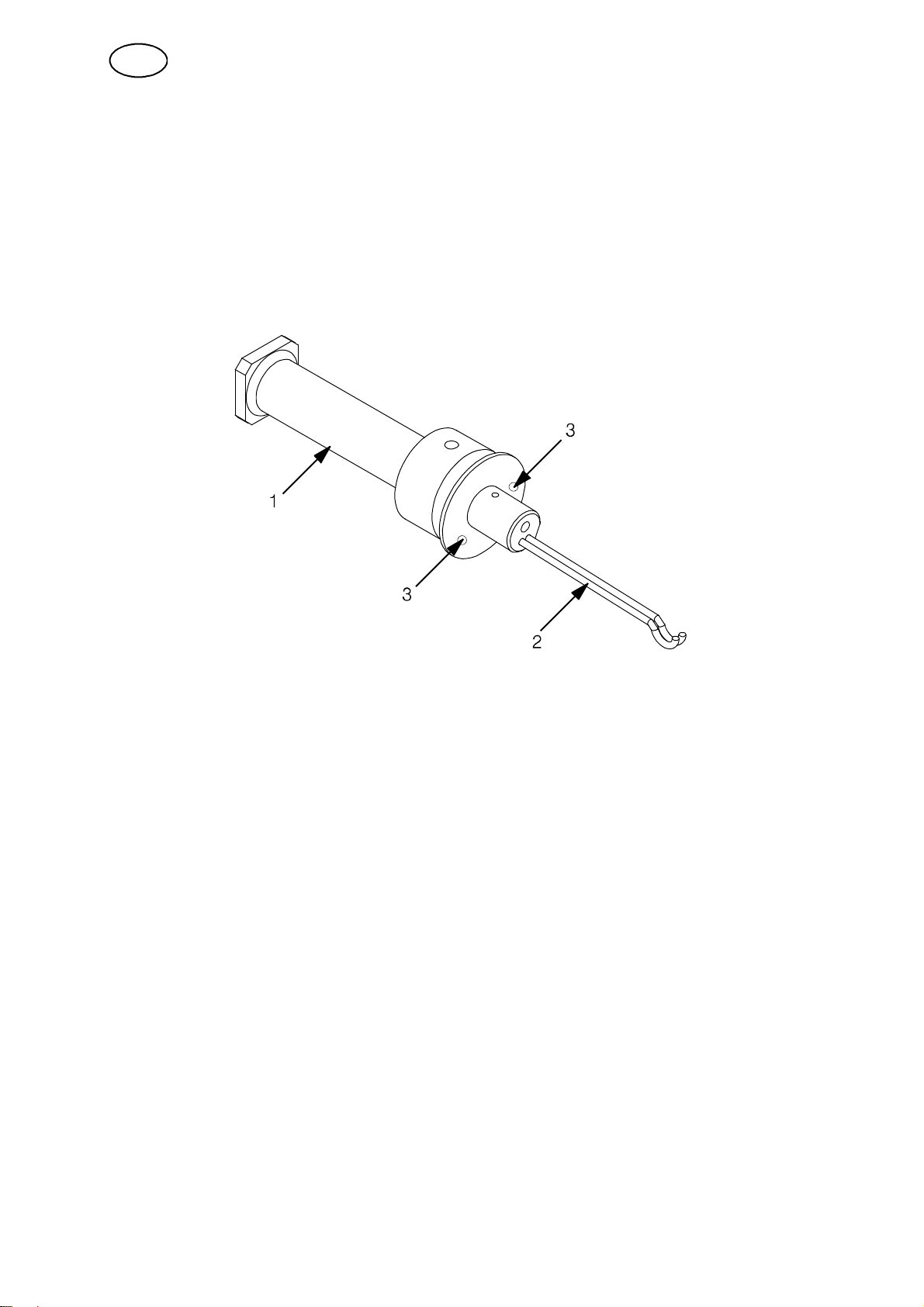
2.4.1 Sensor
The sensor is shaped like a finger. The finger is spring--loaded so that it attempts to
reach the centre position laterally and downwards vertically.
1. Sensor with connection for cable to joint--tracking unit and with bracket for
different tracking fingers at the front.
2. Joint--tracking fingers
3. Stop screws (two) for adjusting finger movement horizontally. The screws enable
settings for different joint types.
hga1d1ea
-- 9 0 --

GB
3 INSTALLATION
3.1 General
The installation must be executed by a professional.
3.2 Installation and connection
1. Measurement information, see the dimension drawings on pages 247--249.
2. Connection, see the diagrams on pages 244--246
3. Check that the required output and voltage is available for complete installation.
4. Fit the guide finger parallel with the motor driven slide cross.
3.3 Tuning the sensor finger
Please refer to ESAB’s service department for tuning the sensor finger.
3.4 Tuning the inductive sensor
Please refer to ESAB’s service department for tuning the inductive sensor.
hga1i1ea
-- 9 1 --
GB
4OPERATION
4.1 General
General safety regulations for the handling of the equipment can be found on
page 85. Read through before you start using the equipment!
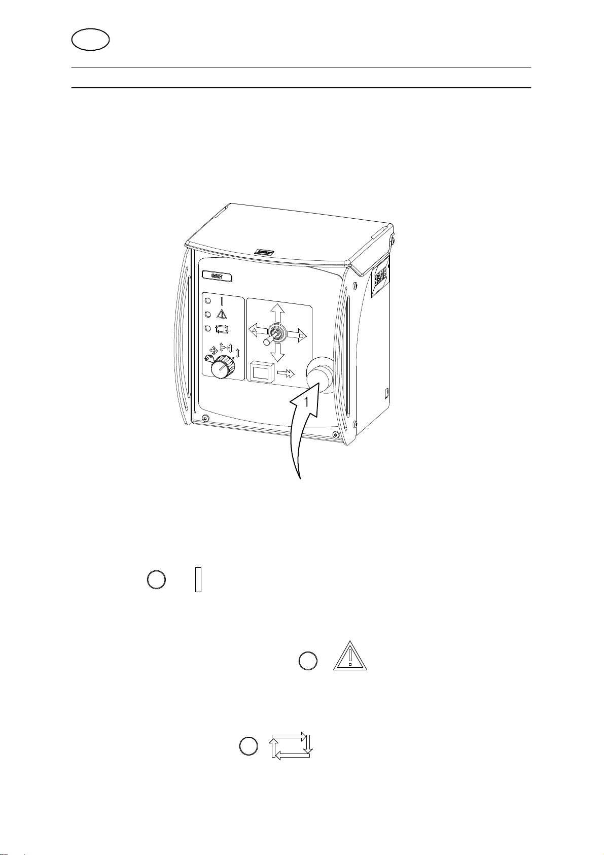
4.2 Joint--tracking unit with control panel
Emergency stop (1)
S One press on the button activates EMERGENCY STOP
NB! An emergency stop must never be reset before the cause of the abnormal
function or signal has been established and rectified.
Signal lamp (white)
S Illuminates when the power has been switched on.
Alarm lamp (automatic joint-tracking) (yellow)
S Illuminates when the guide finger is outside the working range (vertical).
The automatic function is then blocked.
Signal lamp (joint --tracking)
S Illuminates when automatic joint--tracking is in progress.
(green)
hga1o1ea
-- 9 2 --
GB
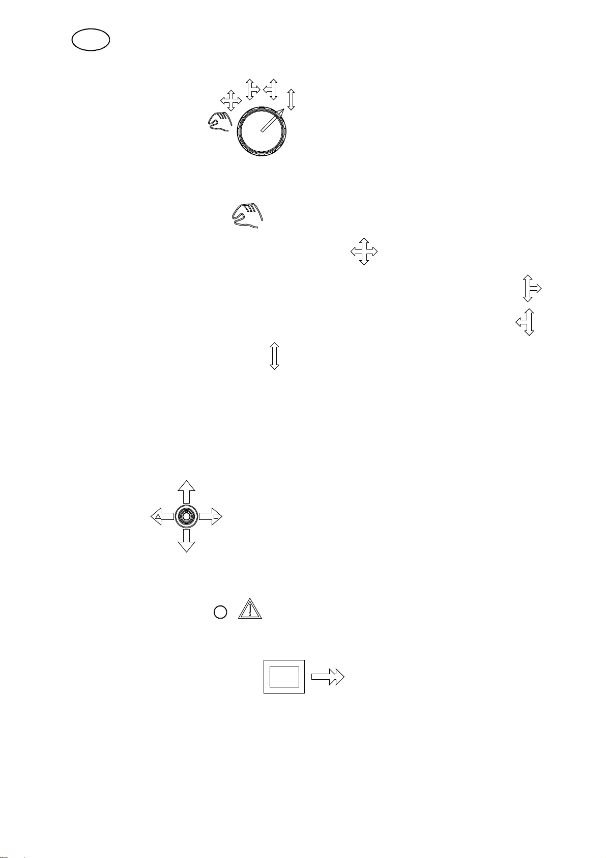
Switch with 5 positions
Selection of joint--tracking and joint--searching options:
S Manual preset -- Position
S Vertical and horizontal joint--tracking -- Position
S Vertical and horizontal joint--tracking with joint--searching to the right -- Position
S Vertical and horizontal joint--tracking with joint--searching to the left -- Position
S Vertical joint--tracking -- Position
NOTE!
If the switch is in a joint--tracking position when the equipment is switched on then
the equipment will not start joint--tracking for safety reasons. To start joint--tracking,
another position m ust be briefly selected before returning to the required position.
Control lever
S Manual control of servo slides Up/Down and Left/Right.
The control lever is always overriding.
When the alarm lamp is illuminated the downward manual movement is
blocked.
Lamp pushbutton (rapid speed)
Selection of low or high speed during manual positioning with the control lever.
S One press on the button activates rapid speed.
A lamp in the button illuminates when the function is activated.
S Return to low speed by pressing the button again
Check that the lamp has gone out before carrying out further commands.
hga1o1ea
-- 9 3 --
GB
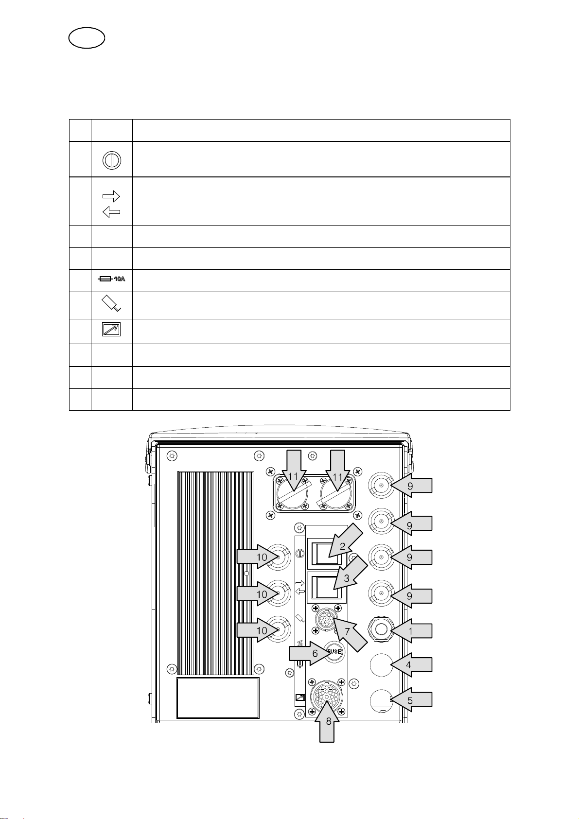
4.3 Joint--tracking unit -- rear section
1 Connection, power supply 42 V
Switch
2
3
4 Socket, for connecting the vertical slide motor
5 Socket, for connecting the horizontal slide motor
6 Control fuse, 10 A slow
7 Sleeve socket (8--pin), for connecting the guide finger.
Power supply On/Off
Switch
For switching the horizontal slide motor’s direction of
movement.
8 Socket (23--pin), for connecting the portable control box.
9 Sockets, for connecting the limit position switch
10 Extra sockets
11 Service contacts
hga1o1ea
-- 9 4 --
 Loading...