


EPP-601
ESAB Precision Plasma Power Source
Instruction Manual
0558007752 06/2012

BE SURE THIS INFORMATION REACHES THE OPERATOR.
YOU CAN GET EXTRA COPIES THROUGH YOUR SUPPLIER.
CAUTION
These INSTRUCTIONS are for experienced operators. If you are not fully familiar with the
principles of operation and safe practices for arc welding and cutting equipment, we urge
you to read our booklet, “Precautions and Safe Practices for Arc Welding, Cutting, and
Gouging,” Form 52-529. Do NOT permit untrained persons to install, operate, or maintain
this equipment. Do NOT attempt to install or operate this equipment until you have read
and fully understand these instructions. If you do not fully understand these instructions,
contact your supplier for further information. Be sure to read the Safety Precautions before installing or operating this equipment.
USER RESPONSIBILITY
This equipment will perform in conformity with the description thereof contained in this manual and accompanying labels and/or inserts when installed, operated, maintained and repaired in accordance with the instructions provided. This equipment must be checked periodically. Malfunctioning or poorly maintained equipment
should not be used. Parts that are broken, missing, worn, distorted or contaminated should be replaced immediately. Should such repair or replacement become necessary, the manufacturer recommends that a telephone
or written request for service advice be made to the Authorized Distributor from whom it was purchased.
This equipment or any of its parts should not be altered without the prior written approval of the manufacturer.
The user of this equipment shall have the sole responsibility for any malfunction which results from improper
use, faulty maintenance, damage, improper repair or alteration by anyone other than the manufacturer or a service facility designated by the manufacturer.
READ AND UNDERSTAND THE INSTRUCTION MANUAL BEFORE INSTALLING OR OPERATING.
PROTECT YOURSELF AND OTHERS!

TABLE OF CONTENTS
Section / Title Page
1.0 Safety Precautions ....................................................................................5
1.1 Safety - English ..................................................................................5
1.2 Safety - Spanish .................................................................................9
1.3 Safety - French .................................................................................13
2.0 Description ..........................................................................................17
2.1 Introduction....................................................................................17
2.2 General Specications ..........................................................................17
2.3 Dimensions and Weight.........................................................................18
3.0 Installation...........................................................................................19
3.1 General ........................................................................................19
3.2 Unpacking .....................................................................................19
3.3 Placement......................................................................................19
3.4 Input Power Connection . . . . . . . . . . . . . . . . . . . . . . . . . . . . . . . . . . . . . . . . . . . . . . . . . . . . . . . . . . . . . . . . . . . . . . . 20
3.5 Output Connections ........................................................................... 22
3.6 Parallel Installation............................................................................. 23
3.7 Interface Cables ................................................................................27
4.0 Operation .......................................................................................... 29
4.1 Block Diagram Circuit Description .............................................................. 29
4.2 Control Panel...................................................................................32
4.3 Sequence of Operation ........................................................................ 36
4.4 Arc Initiation Settings ...........................................................................37
5.0 Maintenance.........................................................................................41
5.1 General.........................................................................................41
5.2 Cleaning .......................................................................................41
5.3 Lubrication.....................................................................................42
6.0 Troubleshooting .................................................................................... 43
6.1 General ....................................................................................... 43
6.2 Fault Indicators . . . . . . . . . . . . . . . . . . . . . . . . . . . . . . . . . . . . . . . . . . . . . . . . . . . . . . . . . . . . . . . . . . . . . . . . . . . . . . . . 43
6.3 Fault Isolation................................................................................. 46
6.4 Testing and Replacing Components . . . . . . . . . . . . . . . . . . . . . . . . . . . . . . . . . . . . . . . . . . . . . . . . . . . . . . . . . . . . 54
6.5 Control Circuit Interface Using J1, J4 and J6 Connectors ......................................... 60
6.6 Auxiliary Main Contactor (K3 & K33) and Solid State Contactor Circuits ........................... 62
6.7 E-Stop (Emergency Stop) and Main Contactor (K1A, K1B and K1C) Circuits ........................ 63
6.8 Arc Current Detector Circuits................................................................... 65
6.9 Current Control Pot and Remote Vref . . . . . . . . . . . . . . . . . . . . . . . . . . . . . . . . . . . . . . . . . . . . . . . . . . . . . . . . . . . 66
6.10 High / Low Cut Current Modes and Mark Mode ..................................................67
6.11 Low Current Range ............................................................................68
6.12 Electrode Current Transducer Circuit............................................................68
7.0 Replacement Parts .................................................................................. 69
7.1 General ....................................................................................... 69
7.2 Ordering ...................................................................................... 69

4

SECTION 1 SAFETY PRECAUTIONS
1.0 Safety Precautions
WARNING: These Safety Precautions are
for your protection. They summarize precautionary information from the references
listed in Additional Safety Information section. Before performing any installation or operating
procedures, be sure to read and follow the safety
precautions listed below as well as all other manuals,
material safety data sheets, labels, etc. Failure to observe
Safety Precautions can result in injury or death.
PROTECT YOURSELF AND OTHERS -Some welding, cutting, and gouging
processes are noisy and require ear
protection. The arc, like the sun, e mits
ultraviolet (UV) and other radiation
and can injure skin and eyes. Hot metal can cause
burns. Training in the proper use of the processes
and equipment is essential to prevent accidents.
Therefore:
1. Always wear safety glasses with side shields in any
work area, even if welding helmets, face shields, and
goggles are also required.
2. Use a face shield tted with the correct lter and
cover plates to protect your eyes, face, neck, and
ears from sparks and rays of the arc when operating or observing operations. Warn bystanders not
to watch the arc and not to expose themselves to
the rays of the electric-arc or hot metal.
3. Wear ameproof gauntlet type gloves, heavy long-
sleeve shirt, cuess trousers, high-topped shoes,
and a welding helmet or cap for hair protection, to
protect against arc rays and hot sparks or hot metal.
A ameproof apron may also be desirable as protection against radiated heat and sparks.
4. Hot sparks or metal can lodge in rolled up sleeves,
trouser cus, or pockets. Sleeves and collars should
be kept buttoned, and open pockets eliminated from
the front of clothing.
5. Protect other personnel from arc rays and hot
sparks with a suitable non-ammable partition or
curtains.
6. Use goggles over safety glasses when chipping slag
or grinding. Chipped slag may be hot and can y far.
Bystanders should also wear goggles over safety
glasses.
1.1 Safety - English
FIRES AND EXPLOSIONS -- Heat from
ames and arcs can start res. Hot
slag or sparks can also cause res and
explosions. Therefore:
1. Remove all combustible materials well away from
the work area or cover the materials with a protective non-ammable covering. Combustible materials
include wood, cloth, sawdust, liquid and gas fuels,
solvents, paints and coatings, paper, etc.
2. Hot sparks or hot metal can fall through cracks or
crevices in oors or wall openings and cause a hidden smoldering re or res on the oor below. Make
certain that such openings are protected from hot
sparks and metal.“
3. Do not weld, cut or perform other hot work until the
workpiece has been completely cleaned so that there
are no substances on the workpiece which might
produce ammable or toxic vapors. Do not do hot
work on closed containers. They may explode.
4. Have re extinguishing equipment handy for instant
use, such as a garden hose, water pail, sand bucket,
or portable re extinguisher. Be sure you are trained
in its use.
5. Do not use equipment beyond its ratings. For example, overloaded welding cable can overheat and
create a re hazard.
6. After completing operations, inspect the work area
to make certain there are no hot sparks or hot metal
which could cause a later re. Use re watchers when
necessary.
7. For additional information, refer to NFPA Standard
51B, "Fire Prevention in Use of Cutting and Welding
Processes", available from the National Fire Protection Association, Batterymarch Park, Quincy, MA
02269.
ELECTRICAL SHOCK -- Contact with
live electrical parts and ground can
cause severe injury or death. DO NOT
use AC welding current in damp areas,
if movement is conned, or if there is
danger of falling.
5
SECTION 1 SAFETY PRECAUTIONS
1. Be sure the power source frame (chassis) is connected to the ground system of the input power.
2. Connect the workpiece to a good electrical
ground.
3. Connect the work cable to the workpiece. A poor
or missing connection can expose you or others
to a fatal shock.
4. Use well-maintained equipment. Replace worn or
damaged cables.
5. Keep everything dry, including clothing, work
area, cables, torch/electrode holder, and power
source.
6. Make sure that all parts of your body are insulated
from work and from ground.
7. Do not stand directly on metal or the earth while
working in tight quarters or a damp area; stand
on dry boards or an insulating platform and wear
rubber-soled shoes.
8. Put on dry, hole-free gloves before turning on the
power.
3. Welders should use the following procedures to
minimize exposure to EMF:
A. Route the electrode and work cables together.
Secure them with tape when possible.
B. Never coil the torch or work cable around your
body.
C. Do not place your body between the torch and
work cables. Route cables on the same side of
your body.
D. Connect the work cable to the workpiece as close
as possible to the area being welded.
E. Keep welding power source and cables as far
away from your body as possible.
FUMES AND GASES -- Fumes and
gases, can cause discomfort or harm,
particularly in conned spaces. Do
not breathe fumes and gases. Shielding gases can cause asphyxiation.
Therefore:
9. Turn o the power before removing your gloves.
10. Refer to ANSI/ASC Standard Z49.1 (listed on
next page) for specic grounding recommendations. Do not mistake the work lead for a ground
cable.
ELECTRIC AND MAGNETIC FIELDS
— May be dangerous. Electric current owing through any conductor causes localized Electric and
Magnetic Fields (EMF). Welding and
cutting current creates EMF around welding cables
and welding machines. Therefore:
1. Welders having pacemakers should consult their
physician before welding. EMF may interfere with
some pacemakers.
2. Exposure to EMF may have other health eects which
are unknown.
1. Always provide adequate ventilation in the work area
by natural or mechanical means. Do not weld, cut, or
gouge on materials such as galvanized steel, stainless steel, copper, zinc, lead, beryllium, or cadmium
unless positive mechanical ventilation is provided.
Do not breathe fumes from these materials.
2. Do not operate near degreasing and spraying operations. The heat or arc rays can react with chlorinated
hydrocarbon vapors to form phosgene, a highly
toxic gas, and other irritant gases.
3. If you develop momentary eye, nose, or throat irritation while operating, this is an indication that
ventilation is not adequate. Stop work and take
necessary steps to improve ventilation in the work
area. Do not continue to operate if physical discomfort persists.
4. Refer to ANSI/ASC Standard Z49.1 (see listing below)
for specic ventilation recommendations.
6

SECTION 1 SAFETY PRECAUTIONS
5. WARNING: This product, when used for welding
or cutting, produces fumes or gases
which contain chemicals known to
the State of California to cause birth
defects and, in some cases, cancer.
(California Health & Safety Code
§25249.5 et seq.)
CYLINDER HANDLING -- Cylinders,
if mishandled, can rupture and violently release gas. Sudden rupture
of cylinder, valve, or relief device can
injure or kill. Therefore:
1. Use the proper gas for the process and use the
proper pressure reducing regulator designed to
operate from the compressed gas cylinder. Do not
use adaptors. Maintain hoses and ttings in good
condition. Follow manufacturer's operating instructions for mounting regulator to a compressed gas
cylinder.
1. Always have qualied personnel perform the installation, troubleshooting, and maintenance work.
Do not perform any electrical work unless you are
qualied to perform such work.
2. Before performing any maintenance work inside a
power source, disconnect the power source from
the incoming electrical power.
3. Maintain cables, grounding wire, connections, power
cord, and power supply in safe working order. Do
not operate any equipment in faulty condition.
4. Do not abuse any equipment or accessories. Keep
equipment away from heat sources such as furnaces,
wet conditions such as water puddles, oil or grease,
corrosive atmospheres and inclement weather.
5. Keep all safety devices and cabinet covers in position
and in good repair.
6. Use equipment only for its intended purpose. Do
not modify it in any manner.
2. Always secure cylinders in an upright position by
chain or strap to suitable hand trucks, undercarriages, benches, walls, post, or racks. Never secure
cylinders to work tables or xtures where they may
become part of an electrical circuit.
3. When not in use, keep cylinder valves closed. Have
valve protection cap in place if regulator is not connected. Secure and move cylinders by using suitable
hand trucks. Avoid rough handling of cylinders.
4. Locate cylinders away from heat, sparks, and ames.
Never strike an arc on a cylinder.
5. For additional information, refer to CGA Standard P-1,
"Precautions for Safe Handling of Compressed Gases
in Cylinders", which is available from Compressed
Gas Association, 1235 Jeerson Davis Highway,
Arlington, VA 22202.
EQUIPMENT MAINTENANCE -- Faulty or
improperly maintained equipment can
cause injury or death. Therefore:
ADDITIONAL SAFETY INFORMATION -- For
more information on safe practices for
electric arc welding and cutting equipment, ask your supplier for a copy of
"Precautions and Safe Practices for Arc
Welding, Cutting and Gouging", Form
52-529.
The following publications, which are available from
the American Welding Society, 550 N.W. LeJuene Road,
Miami, FL 33126, are recommended to you:
1. ANSI/ASC Z49.1 - "Safety in Welding and Cutting"
2. AWS C5.1 - "Recommended Practices for Plasma Arc
Welding"
3. AWS C5.2 - "Recommended Practices for Plasma Arc
Cutting"
4. AWS C5.3 - "Recommended Practices for Air Carbon
Arc Gouging and Cutting"
7

SECTION 1 SAFETY PRECAUTIONS
5. AWS C5.5 - "Recommended Practices for Gas Tungsten Arc Welding“
6. AWS C5.6 - "Recommended Practices for Gas Metal
Arc Welding"“
7. AWS SP - "Safe Practices" - Reprint, Welding Handbook.
8. ANSI/AWS F4.1, "Recommended Safe Practices for
Welding and Cutting of Containers That Have Held
Hazardous Substances."
MEANING OF SYMBOLS - As used
throughout this manual: Means Attention! Be Alert! Your safety is involved.
Means immediate hazards which,
if not avoided, will result in immediate, serious personal injury
or loss of life.
Means potential hazards which
could result in personal injury or
loss of life.
Means hazards which could result
in minor personal injury.
8

SECCION 1 SEGURIDAD
1.2 Safety - Spanish
ADVERTENCIA: Estas Precauciones de Se-
guridad son para su protección. Ellas hacen
resumen de información proveniente de las
referencias listadas en la sección "Información Adicional Sobre La Seguridad". Antes de hacer cualquier
instalación o procedimiento de operación , asegúrese
de leer y seguir las precauciones de seguridad listadas
a continuación así como también todo manual, hoja
de datos de seguridad del material, calcomanias, etc.
El no observar las Precauciones de Seguridad puede
resultar en daño a la persona o muerte.
PROTEJASE USTED Y A LOS DEMAS-Algunos procesos de soldadura, corte
y ranurado son ruidosos y requiren
protección para los oídos. El arco,
como el sol , emite rayos ultravioleta
(UV) y otras radiaciones que pueden dañar la piel
y los ojos. El metal caliente causa quemaduras. EL
entrenamiento en el uso propio de los equipos y
sus procesos es esencial para prevenir accidentes.
Por lo tanto:
1. U tilice gafas de seguridad con protección a los lados
siempre que esté en el área de trabajo, aún cuando
esté usando careta de soldar, protector para su cara
u otro tipo de protección.
2. Use una careta que tenga el ltro correcto y lente
para proteger sus ojos, cara, cuello, y oídos de las
chispas y rayos del arco cuando se esté operando y
observando las operaciones. Alerte a todas las personas cercanas de no mirar el arco y no exponerse
a los rayos del arco eléctrico o el metal fundido.
3. Use guantes de cuero a prueba de fuego, camisa
pesada de mangas largas, pantalón de ruedo liso,
zapato alto al tobillo, y careta de soldar con capucha
para el pelo, para proteger el cuerpo de los rayos y
chispas calientes provenientes del metal fundido.
En ocaciones un delantal a prueba de fuego es
necesario para protegerse del calor radiado y las
chispas.
4. Chispas y partículas de metal caliente puede alojarse
en las mangas enrolladas de la camisa , el ruedo del
pantalón o los bolsillos. Mangas y cuellos deberán
mantenerse abotonados, bolsillos al frente de la
camisa deberán ser cerrados o eliminados.
5. Proteja a otras personas de los rayos del arco y chis-
pas calientes con una cortina adecuada no-amable
como división.
6. Use careta protectora además de sus gafas de segu-
ridad cuando esté removiendo escoria o puliendo.
La escoria puede estar caliente y desprenderse con
velocidad. Personas cercanas deberán usar gafas
de seguridad y careta protectora.
FUEGO Y EXPLOSIONES -- El calor de
las amas y el arco pueden ocacionar
fuegos. Escoria caliente y las chispas
pueden causar fuegos y explosiones.
Por lo tanto:
1. Remueva todo material combustible lejos del área
de trabajo o cubra los materiales con una cobija a
prueba de fuego. Materiales combustibles incluyen
madera, ropa, líquidos y gases amables, solventes,
pinturas, papel, etc.
2. Chispas y partículas de metal pueden introducirse en
las grietas y agujeros de pisos y paredes causando
fuegos escondidos en otros niveles o espacios.
Asegúrese de que toda grieta y agujero esté cubierto
para proteger lugares adyacentes contra fuegos.
3. No corte, suelde o haga cualquier otro trabajo
relacionado hasta que la pieza de trabajo esté totalmente limpia y libre de substancias que puedan
producir gases inamables o vapores tóxicos. No
trabaje dentro o fuera de contenedores o tanques
cerrados. Estos pueden explotar si contienen vapores
inamables.
4. Tenga siempre a la mano equipo extintor de fuego
para uso instantáneo, como por ejemplo una
manguera con agua, cubeta con agua, cubeta con
arena, o extintor portátil. Asegúrese que usted esta
entrenado para su uso.
5. No use el equipo fuera de su rango de operación. Por
ejemplo, el calor causado por cable sobrecarga en
los cables de soldar pueden ocasionar un fuego.
6. Después de termirar la operación del equipo, inspeccione el área de trabajo para cerciorarse de que las
chispas o metal caliente ocasionen un fuego más
tarde. Tenga personal asignado para vigilar si es
necesario.
7. Para información adicional , haga referencia a la
publicación NFPA Standard 51B, "Fire Prevention in
Use of Cutting and Welding Processes", disponible
a través de la National Fire Protection Association,
Batterymarch Park, Quincy, MA 02269.
CHOQUE ELECTRICO -- El contacto
con las partes eléctricas energizadas
y tierra puede causar daño severo o
muerte. NO use soldadura de corri-
ente alterna (AC) en áreas húmedas,
de movimiento connado en lugares estrechos o
si hay posibilidad de caer al suelo.
9

SECCION 1 SEGURIDAD
1. Asegúrese de que el chasis de la fuente de poder
esté conectado a tierra através del sistema de
electricidad primario.
2. Conecte la pieza de trabajo a un buen sistema de
tierra física.
3. Conecte el cable de retorno a la pieza de trabajo.
Cables y conductores expuestos o con malas
conexiones pueden exponer al operador u otras
personas a un choque eléctrico fatal.
4. Use el equipo solamente si está en buenas condiciones. Reemplaze cables rotos, dañados o con
conductores expuestos.
5. M antenga todo seco, incluyendo su ropa, el área de
trabajo, los cables, antorchas, pinza del electrodo,
y la fuente de poder.
6. Asegúrese que todas las partes de su cuerpo están
insuladas de ambos, la pieza de trabajo y tierra.
7. No se pare directamente sobre metal o tierra mientras trabaja en lugares estrechos o áreas húmedas;
trabaje sobre un pedazo de madera seco o una
plataforma insulada y use zapatos con suela de
goma.
8. Use guantes secos y sin agujeros antes de energizar
el equipo.
9. Apage el equipo antes de quitarse sus guantes.
10. Use como referencia la publicación ANSI/ASC
Standard Z49.1 (listado en la próxima página) para
recomendaciones especícas de como conectar el
equipo a tierra. No confunda el cable de soldar a
la pieza de trabajo con el cable a tierra.
CAMPOS ELECTRICOS Y MAGNETICOS - Son peligrosos. La corriente
eléctrica uye através de cualquier
conductor causando a nivel local
Campos Eléctricos y Magnéticos
(EMF). Las corrientes en el área de corte y soldadura,
crean EMF alrrededor de los cables de soldar y las
maquinas. Por lo tanto:
1. Soldadores u Operadores que use marca-pasos para
el corazón deberán consultar a su médico antes de
soldar. El Campo Electromagnético (EMF) puede
interferir con algunos marca-pasos.
2. Exponerse a campos electromagnéticos (EMF) puede
causar otros efectos de salud aún desconocidos.
3. Los soldadores deberán usar los siguientes procedimientos para minimizar exponerse al EMF:
A. Mantenga el electrodo y el cable a la pieza de
trabajo juntos, hasta llegar a la pieza que usted
quiere soldar. Asegúrelos uno junto al otro con
cinta adhesiva cuando sea posible.
B. Nunca envuelva los cables de soldar alrededor
de su cuerpo.
C. Nunca ubique su cuerpo entre la antorcha y el
cable, a la pieza de trabajo. Mantega los cables a
un sólo lado de su cuerpo.
D. Conecte el cable de trabajo a la pieza de trabajo
lo más cercano posible al área de la soldadura.
E. Mantenga la fuente de poder y los cables de soldar
lo más lejos posible de su cuerpo.
HUMO Y GASES -- El humo y los
gases, pueden causar malestar o
daño, particularmente en espacios
sin ventilación. No inhale el humo
o gases. El gas de protección puede
causar falta de oxígeno.
Por lo tanto:
1. Siempre provea ventilación adecuada en el área
de trabajo por medio natural o mecánico. No solde,
corte, o ranure materiales con hierro galvanizado,
acero inoxidable, cobre, zinc, plomo, berílio, o cadmio a menos que provea ventilación mecánica
positiva . No respire los gases producidos por
estos materiales.
2. No opere cerca de lugares donde se aplique sub-
stancias químicas en aerosol. El calor de los rayos
del arco pueden reaccionar con los vapores de
hidrocarburo clorinado para formar un fosfógeno,
o gas tóxico, y otros irritant es.
3. Si momentáneamente desarrolla inrritación de
ojos, nariz o garganta mientras est á operando, es
indicación de que la ventilación no es apropiada.
Pare de trabajar y tome las medidas necesarias
para mejorar la ventilación en el área de trabajo.
No continúe operando si el malestar físico persiste.
4. Haga referencia a la publicación ANSI/ASC Standard
Z49.1 (Vea la lista a continuación) para recomendaciones especícas en la ventilación.
10

SECCION 1 SEGURIDAD
5. ADVERTENCIA-- Este producto cuando se utiliza para soldaduras o cortes,
produce humos o gases, los
cuales contienen químicos
conocidos por el Estado de California de causar defectos en el
nacimiento, o en algunos casos,
Cancer. (California Health &
Safety Code §25249.5 et seq.)
MANEJO DE CILINDROS-- Los
cilindros, si no son manejados
correctamente, pueden romperse y liberar violentamente
gases. Rotura repentina del
cilindro, válvula, o válvula de
escape puede causar daño o
muerte. Por lo tanto:
1. Utilize el gas apropiado para el proceso y utilize
un regulador diseñado para operar y reducir la
presión del cilindro de gas . No utilice adaptadores. Mantenga las mangueras y las conexiones
en buenas condiciones. Observe las instrucciones
de operación del manufacturero para montar el
regulador en el cilindro de gas comprimido.
2. Asegure siempre los cilindros en posición vertical
y amárrelos con una correa o cadena adecuada
para asegurar el cilindro al carro, transportes, tablilleros, paredes, postes, o armazón. Nunca asegure
los cilindros a la mesa de trabajo o las piezas que
son parte del circuito de soldadura . Este puede ser
parte del circuito elélectrico.
3. Cuando el cilindro no está en uso, mantenga la
válvula del cilindro cerrada. Ponga el capote de
protección sobre la válvula si el regulador no
está conectado. Asegure y mueva los cilindros
utilizando un carro o transporte adecuado. Evite
el manejo brusco de los
1. Siempre tenga personal cualicado para efectuar l a instalación, diagnóstico, y mantenimiento
del equipo. No ejecute ningún trabajo eléctrico a
menos que usted esté cualicado para hacer el
trabajo.
2. Antes de dar mantenimiento en el interior de la
fuente de poder, desconecte la fuente de poder
del suministro de electricidad primaria.
3. Mantenga los cables, cable a tierra, conexciones,
cable primario, y cualquier otra fuente de poder
en buen estado operacional. No opere ningún
equipo en malas condiciones.
4. No abuse del equipo y sus accesorios. Mantenga
el equipo lejos de cosas que generen calor como
hornos, también lugares húmedos como charcos
de agua , aceite o grasa, atmósferas corrosivas y
las inclemencias del tiempo.
5. Mantenga todos los artículos de seguridad y
coverturas del equipo en su posición y en buenas
condiciones.
6. Use el equipo sólo para el propósito que fue
diseñado. No modique el equipo en ninguna
manera.
INFORMACION ADICIONAL DE SEGURIDAD -- Para más información sobre las
prácticas de seguridad de los equipos de
arco eléctrico para soldar y cortar, pregunte
a su suplidor por una copia de "Precautions
and Safe Practices for Arc Welding, Cutting
and Gouging-Form 52-529.
Las siguientes publicaciones, disponibles através de
la American Welding Society, 550 N.W. LeJuene Road,
Miami, FL 33126, son recomendadas para usted:
1. ANSI/ASC Z49.1 - "Safety in Welding and Cutting"
2. AWS C5.1 - "Recommended Practices for Plasma Arc
Welding"
MANTENIMIENTO DEL EQUIPO -- Equipo
defectuoso o mal mantenido puede causar daño o muerte. Por lo tanto:
3. AWS C5.2 - "Recommended Practices for Plasma Arc
Cutting"
4. AWS C5.3 - "Recommended Practices for Air Carbon
Arc Gouging and Cutting"
11

SECCION 1 SEGURIDAD
SIGNIFICADO DE LOS SIMBOLOS
-- Según usted avanza en la lectura
de este folleto: Los Símbolos Signican ¡Atención! ¡Esté Alerta! Se
trata de su seguridad.
Signica riesgo inmediato que,
de no ser evadido, puede resultar
inmediatamente en serio daño
personal o la muerte.
Signica el riesgo de un peligro
potencial que puede resultar en
serio daño personal o la muerte.
Signica el posible riesgo que
puede resultar en menores daños
a la persona.
12
SECTION 1 SÉCURITÉ
1.3 Safety - French
AVERTISSEMENT : Ces règles de sécurité
ont pour but d'assurer votre protection. Ils
récapitulent les informations de précaution
provenant des références dans la section
des Informations de sécurité supplémentaires. Avant de
procéder à l'inst allation ou d'utiliser l'unité, assurez-vous
de lire et de suivre les précautions de sécurité ci-dessous, dans les manuels, les ches d'information sur la
sécurité du matériel et sur les étiquettes, etc. Tout défaut
d'observer ces précautions de sécurité peut entraîner
des blessures graves ou mortelles.
PROTÉGEZ-VOUS -- Les processus de
soudage, de coupage et de gougeage
produisent un niveau de bruit élevé et
exige l'emploi d'une protection auditive. L'arc, tout
comme le soleil, émet des rayons ultraviolets en plus
d'autre rayons qui peuvent causer des blessures à la
peau et les yeux. Le métal incandescent peut causer
des brûlures. Une formation reliée à l'usage des
processus et de l'équipement est essentielle pour
prévenir les accidents. Par conséquent:
1. Portez des lunettes protectrices munies d'écrans la-
téraux lorsque vous êtes dans l'aire de travail, même
si vous devez porter un casque de soudeur, un écran
facial ou des lunettes étanches.
2. Portez un écran facial muni de verres ltrants et de
plaques protectrices appropriées an de protéger
vos yeux, votre visage, votre cou et vos oreilles des
étincelles et des rayons de l'arc lors d'une opération
ou lorsque vous observez une opération. Avertissez
les personnes se trouvant à proximité de ne pas regarder l'arc et de ne pas s'exposer aux rayons de l'arc
électrique ou le métal incandescent.
3. Portez des gants ignifugiés à crispin, une chemise
épaisse à manches longues, des pantalons sans
rebord et des chaussures montantes an de vous
protéger des rayons de l'arc, des étincelles et du métal
incandescent, en plus d'un casque de soudeur ou
casquette pour protéger vos cheveux. Il est également
recommandé de porter un tablier ininammable an
de vous protéger des étincelles et de la chaleur par
rayonnement.
4. Les étincelles et les projections de métal incandescent
risquent de se loger dans les manches retroussées,
les rebords de pantalons ou les poches. Il est recommandé de garder boutonnés le col et les manches et
de porter des vêtements sans poches en avant.
5. Protégez toute personne se trouvant à proximité des
étincelles et des rayons de l'arc à l'aide d'un rideau ou
d'une cloison ininammable.
6. Portez des lunettes étanches par dessus vos lunettes
de sécurité lors des opérations d'écaillage ou de
meulage du laitier. Les écailles de laitier incandescent
peuvent être projetées à des distances considérables.
Les personnes se trouvant à proximité doivent également porter des lunettes étanches par dessus leur
lunettes de sécurité.
INCENDIES ET EXPLOSIONS -- La
chaleur provenant des ammes ou de
l'arc peut provoquer un incendie. Le
laitier incandescent ou les étincelles
peuvent également provoquer un
incendie ou une explosion. Par conséquent :
1. Éloignez susamment tous les matériaux combustibles de l'aire de travail et recouvrez les matériaux
avec un revêtement protecteur ininammable. Les
matériaux combustibles incluent le bois, les vêtements, la sciure, le gaz et les liquides combustibles,
les solvants, les peintures et les revêtements, le
papier, etc.
2. Les étincelles et les projections de métal incandescent peuvent tomber dans les ssures dans
les planchers ou dans les ouvertures des murs et
déclencher un incendie couvant à l'étage inférieur
Assurez-vous que ces ouvertures sont bien protégées
des étincelles et du métal incandescent.
3. N'exécutez pas de soudure, de coupe ou autre travail à chaud avant d'avoir complètement nettoyé la
surface de la pièce à traiter de façon à ce qu'il n'ait
aucune substance présente qui pourrait produire
des vapeurs inammables ou toxiques. N'exécutez
pas de travail à chaud sur des contenants fermés
car ces derniers pourraient exploser.
4. Assurez-vous qu'un équipement d'extinction
d'incendie est disponible et prêt à servir, tel qu'un
tuyau d'arrosage, un seau d'eau, un seau de sable
ou un extincteur portatif. Assurez-vous d'être bien
instruit par rapport à l'usage de cet équipement.
5. Assurez-vous de ne pas excéder la capacité de
l'équipement. Par exemple, un câble de soudage
surchargé peut surchauer et provoquer un incendie.
6. Une fois les opérations terminées, inspectez l'aire de
travail pour assurer qu'aucune étincelle ou projection de métal incandescent ne risque de provoquer
un incendie ultérieurement. Employez des guetteurs
d'incendie au besoin.
7. Pour obtenir des informations supplémentaires,
consultez le NFPA Standard 51B, "Fire Prevention in
Use of Cutting and Welding Processes", disponible au
National Fire Protection Association, Batterymarch
Park, Quincy, MA 02269.
CHOC ÉLECTRIQUE -- Le contact avec
des pièces électriques ou les pièces
de mise à la terre sous tension peut
causer des blessures graves ou mor-
telles. NE PAS utiliser un courant de
soudage c.a. dans un endroit humide, en espace
restreint ou si un danger de chute se pose.
13

SECTION 1 SÉCURITÉ
1. Assurez-vous que le châssis de la source
d'alimentation est branché au système de mise à
la terre de l'alimentation d'entrée.
2. Branchez la pièce à traiter à une bonne mise de
terre électrique.
3. Branchez le câble de masse à la pièce à traiter et
assurez une bonne connexion an d'éviter le risque
de choc électrique mortel.
4. Utilisez toujours un équipement correctement
entretenu. Remplacez les câbles usés ou endommagés.
5. Veillez à garder votre environnement sec, incluant
les vêtements, l'aire de travail, les câbles, le porteélectrode/torche et la source d'alimentation.
6. Assurez-vous que tout votre corps est bien isolé
de la pièce à traiter et des pièces de la mise à la
terre.
7. Si vous devez eectuer votre travail dans un espace
restreint ou humide, ne tenez vous pas directement sur le métal ou sur la terre; tenez-vous sur
des planches sèches ou une plate-forme isolée et
portez des chaussures à semelles de caoutchouc.
8. Avant de mettre l'équipement sous tension, isolez
vos mains avec des gants secs et sans trous.
9. Mettez l'équipement hors tension avant d'enlever
vos gants.
10. Consultez ANSI/ASC Standard Z49.1 (listé à
la page suivante) pour des recommandations
spéciques concernant les procédures de mise à
la terre. Ne pas confondre le câble de masse avec
le câble de mise à la terre.
CHAMPS ÉLECTRIQUES ET MAGNÉTIQUES — comportent un risque
de danger. Le courant électrique
qui passe dans n'importe quel con-
ducteur produit des champs électriques et magnétiques localisés. Le soudage et le
courant de coupage créent des champs électriques
et magnétiques autour des câbles de soudage et
l'équipement. Par conséquent :
1. Un soudeur ayant un stimulateur cardiaque doit
consulter son médecin avant d'entreprendre une
opération de soudage. Les champs électriques et
magnétiques peuvent causer des ennuis pour certains stimulateurs cardiaques.
2. L'exposition à des champs électriques et magné-
tiques peut avoir des eets néfastes inconnus pour
la santé.
3. Les soudeurs doivent suivre les procédures suivantes
pour minimiser l'exposition aux champs électriques
et magnétiques :
A. Acheminez l'électrode et les câbles de masse
ensemble. Fixez-les à l'aide d'une bande adhésive
lorsque possible.
B. Ne jamais enrouler la torche ou le câble de masse
autour de votre corps.
C. Ne jamais vous placer entre la torche et les câbles
de masse. Acheminez tous les câbles sur le même
côté de votre corps.
D. Branchez le câble de masse à la pièce à traiter le
plus près possible de la section à souder.
E. Veillez à garder la source d'alimentation pour le
soudage et les câbles à une distance appropriée
de votre corps.
LES VAPEURS ET LES GAZ -- peuvent
causer un malaise ou des dommages
corporels, plus particulièrement
dans les espaces restreints. Ne respirez pas les vapeurs et les gaz. Le
gaz de protection risque de causer
l'asphyxie. Par conséquent :
1. Assurez en permanence une ventilation adéquate
dans l'aire de travail en maintenant une ventilation naturelle ou à l'aide de moyens mécanique.
N'eectuez jamais de travaux de soudage, de coupage ou de gougeage sur des matériaux tels que
l'acier galvanisé, l'acier inoxydable, le cuivre, le zinc,
le plomb, le berylliym ou le cadmium en l'absence
de moyens mécaniques de ventilation ecaces. Ne
respirez pas les vapeurs de ces matériaux.
2. N'eectuez jamais de travaux à proximité d'une
opération de dégraissage ou de pulvérisation.
Lorsque la chaleur
ou le rayonnement de l'arc entre en contact avec les
vapeurs d'hydrocarbure chloré, ceci peut déclencher
la formation de phosgène ou d'autres gaz irritants,
tous extrêmement toxiques.
3. Une irritation momentanée des yeux, du nez ou de la
gorge au cours d'une opération indique que la ventilation n'est pas adéquate. Cessez votre travail an
de prendre les mesures nécessaires pour améliorer
la ventilation dans l'aire de travail. Ne poursuivez
pas l'opération si le malaise persiste.
4. Consultez ANSI/ASC Standard Z49.1 (à la page
suivante) pour des recommandations spéciques
concernant la ventilation.
14

SECTION 1 SÉCURITÉ
5. AVERTISSEMENT : Ce produit, lorsqu'il est utilisé
dans une opération de soudage ou de
coupage, dégage des vapeurs ou des
gaz contenant des chimiques considéres par l'état de la Californie comme
étant une cause des malformations
congénitales et dans certains cas, du
cancer. (California Health & Safety
Code §25249.5 et seq.)
MANIPULATION DES CYLINDRES -La manipulation d'un cylindre, sans
observer les précautions nécessaires,
peut produire des fissures et un
échappement dangereux des gaz.
Une brisure soudaine du cylindre, de la soupape ou
du dispositif de surpression peut causer des blessures graves ou mortelles. Par conséquent :
1. Utilisez toujours le gaz prévu pour une opération
et le détendeur approprié conçu pour utilisation
sur les cylindres de gaz comprimé. N'utilisez jamais
d'adaptateur. Maintenez en bon état les tuyaux et
les raccords. Observez les instructions d'opération
du fabricant pour assembler le détendeur sur un
cylindre de gaz comprimé.
2. Fixez les cylindres dans une position verticale, à
l'aide d'une chaîne ou une sangle, sur un chariot
manuel, un châssis de roulement, un banc, un mur,
une colonne ou un support convenable. Ne xez
jamais un cylindre à un poste de travail ou toute autre
dispositif faisant partie d'un circuit électrique.
3. Lorsque les cylindres ne servent pas, gardez les
soupapes fermées. Si le détendeur n'est pas branché, assurez-vous que le bouchon de protection de
la soupape est bien en place. Fixez et déplacez les
cylindres à l'aide d'un chariot manuel approprié.
Toujours manipuler les cylindres avec soin.
4. Placez les cylindres à une distance appropriée
de toute source de chaleur, des étincelles et des
ammes. Ne jamais amorcer l'arc sur un cylindre.
5. Pour de l'information supplémentaire, consultez
CGA Standard P-1, "Precautions for Safe Handling
of Compressed Gases in Cylinders", mis à votre disposition par le Compressed Gas Association, 1235
Jeerson Davis Highway, Arlington, VA 22202.
ENTRETIEN DE L'ÉQUIPEMENT -- Un équipement entretenu de façon défectueuse ou
inadéquate peut causer des blessures
graves ou mortelles. Par conséquent :
1. Efforcez-vous de toujours confier les tâches
d'installation, de dépannage et d'entretien à un
personnel qualié. N'eectuez aucune réparation
électrique à moins d'être qualié à cet eet.
2. Avant de procéder à une tâche d'entretien à
l'intérieur de la source d'alimentation, débranchez
l'alimentation électrique.
3. Maintenez les câbles, les ls de mise à la terre, les
branchements, le cordon d'alimentation et la source
d'alimentation en bon état. N'utilisez jamais un
équipement s'il présente une défectuosité quelconque.
4. N'utilisez pas l'équipement de façon abusive. Gardez
l'équipement à l'écart de toute source de chaleur,
notamment des fours, de l'humidité, des aques
d'eau, de l'huile ou de la graisse, des atmosphères
corrosives et des intempéries.
5. Laissez en place tous les dispositifs de sécurité et
tous les panneaux de la console et maintenez-les
en bon état.
6. Utilisez l'équipement conformément à son usage
prévu et n'eectuez aucune modication.
INFORMATIONS SUPPLÉMENTAIRES RELATIVES À LA SÉCURITÉ -- Pour obtenir de
l'information supplémentaire sur les règles
de sécurité à observer pour l'équipement
de soudage à l'arc électrique et le coupage,
demandez un exemplaire du livret "Precautions and Safe Practices for Arc Welding,
Cutting and Gouging", Form 52-529.
Les publications suivantes sont également recommandées et mises à votre disposition par l'American Welding
Society, 550 N.W. LeJuene Road, Miami, FL 33126 :
1. ANSI/ASC Z49.1 - "Safety in Welding and Cutting"
2. AWS C5.1 - "Recommended Practices for Plasma Arc
Welding"
3. AWS C5.2 - "Recommended Practices for Plasma Arc
Cutting"
4. AWS C5.3 - "Recommended Practices for Air Carbon
Arc Gouging and Cutting"
15

SECTION 1 SÉCURITÉ
SIGNIFICATION DES SYMBOLES
Ce symbole, utilisé partout dans ce manuel,
signie "Attention" ! Soyez vigilant ! Votre
sécurité est en jeu.
DANGER
Signie un danger immédiat. La situation peut
entraîner des blessures graves ou mortelles.
AVERTISSEMENT
Signie un danger potentiel qui peut entraîner des
blessures graves ou mortelles.
ATTENTION
Signie un danger qui peut entraîner des blessures
corporelles mineures.
16

SECTION 2 DESCRIPTION
2.1 Introduction
The EPP power source is designed for marking and high speed plasma mechanized cutting applications. It can
be used with other ESAB products such as the PT-19XLS, PT-600 and PT-36 torches along with the numerous
computerized gas regulation and switching systems.
• 10 to 100 amperes for marking in low current range
• 50 to 600 amperes cutting in high current range
• 35 to 100 amperes cutting in low current range
• Forced air cooled
• Solid state DC power
• Input voltage protection
• Local or remote front panel control
• Thermal switch protection for main transformer and power semiconductor components
• Top lifting rings or base forklift clearance for transport
• Parallel supplemental power source capabilities to extend current output range.
2.2 General Specications
EPP-601 Input/Output Information
EPP-601
380V 50/60HZ
380V TAPS
Part Number
Input Voltage (3-Phase) 380VAC 380VAC 400VAC 460VAC 575VAC
Input Current (3-Phase) 217A RMS 217A RMS 206A RMS 179A RMS 143A RMS
Input Frequency 50 HZ 50 HZ 50 HZ 60 HZ 60 HZ
Input KVA 142.8 KVA 142.8 K VA 142.7 KVA 142.6 KVA 142.4 K VA
Input Power 128 .5 KW 128 .5 KW 128 .4 KW 128 .4 KW 128 .2 KW
Input Power Factor 90% 90% 90% 90% 90%
Recommended Input
Power Cable
Input Fuse (Recommended) 250A 250A 250A 250A 200A
Output Open Circuit Voltage
(OCV) (High Range Cutting)
Output Open Circuit Voltage
(OCV) (Low Range Cutting)
Output Open Circuit Voltage
(OCV) (Marking)
Output Cutting High Range
(100% Duty)
Output Cutting Low Range
(100% Duty)
Output Marking Low Range
(100% Duty)
Output Power (100% Duty) 120 KW
*4/0 AWG *4/0 AWG *4/0 AWG *3/0 AWG *1/0 AWG
430VDC 406VDC 427VDC 431VDC 431VDC
414VDC 393VDC 413VD C 415VDC 415V DC
360VDC 342VDC 369VDC 360VDC 360VDC
EPP-601
380V 50/60HZ
40 0V TAPS
0558007733 0558007734 0558007735
50A @ 100V TO 600A @ 200V
35A @ 94V TO 100A @ 120V
10A @ 84V TO 100A @ 120V
EPP-601
400V 50/60HZ
EPP-601
460V 60HZ
EPP-601
575V 60HZ
* Fuse sizes per National Electrical Code for a 90° C (194˚ F) rated copper conductors @ 40° C (104˚ F) ambient. Not more
than three conductors in raceway or cable. Local codes should be followed if they specify sizes other than those listed
above.
17
SECTION 2 DESCRIPTION
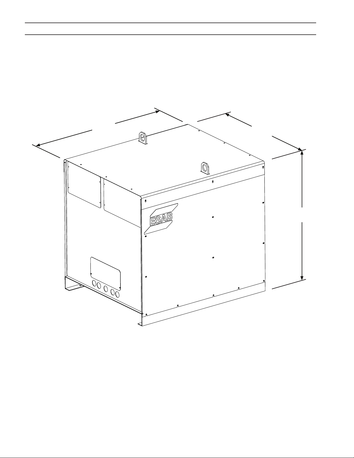
2.3 Dimensions and Weight
1143 m m
45.00”
946 mm
37. 25”
1022 mm
40.25”
Weight = 850 kg. (1870 lbs.)
18

SECTION 3 INSTALLATION
3.1 General
FAILURE TO FOLLOW INSTRUCTION S COULD LEAD TO DEATH, INJURY
OR DAMAGED PROPERTY. FOLLOW THESE INSTRUCTIONS TO PRE
WARNING
3.2 Unpacking
CAUTIONCAUTION
• Inspect for transit damage immediately upon receipt.
• Remove all components from shipping container and check for loose parts in container.
• Inspect louvers for air obstructions.
VENT INJURY OR PROPERTY DAMAGE. YOU MUST COMPLY WITH LO
CAL, STATE AND NATIONAL ELECTRICAL AND SAFETY CODES.
Using one lifting eye will damage sheet metal and frame.
Use both lifting eyes when transporting with overhead method.
3.3 Placement
Note:
Use both lifting eyes when transporting from overhead.
• A minimum of 1 M (3 ft.) clearance on front and back for cooling air ow.
• Plan for top panel and side panels having to be removed for maintenance, cleaning and inspection.
• Locate the EPP-601 relatively close to a properly fused electrical power supply.
• Keep area beneath power source clear for cooling air ow.
• Environment should be relatively free of dust, fumes and excessive heat. These factors will aect cool-
ing eciency.
Conductive dust and dirt inside power source may cause arc ash-
CAUTION
over. Equipment damage may occur. Electrical shorting may occur
if dust is allowed to build-up inside power source. See maintenance
section.
19

SECTION 3 INSTALLATION
3.4 Input Power Connection
ELECTRIC SHOCK CAN KILL!
PROVIDE MAXIMUM PROTECTION AGAINST ELECTRICAL SHOCK.
WARNING
3.4.1 Primary Power
EPP-601 is a 3-phase unit. Input power must be provided from a line (wall) disconnect switch that contains fuses
or circuit breakers in accordance to local regulations.
Please refer to table under “General Specications” in Subsection 2.2 for recommended cable and input fuse sizes.
BEFORE ANY CON NECTIONS ARE MADE I NSIDE THE MACHINE, OPEN
THE LINE WALL DISCONNECT SWITCH TO TURN POWER OFF.
Note:
To estimate the input current for a wide range of output conditions, use the formula below.
(V arc) x (I arc) x 0.688
(V line)
NOTICE
Input current =
Dedicated power line may be necessary.
EPP-601 is equipped with line voltage compensation but to avoid
impaired performance due to an overloaded circuit, a dedicated
power line may be required.
20

SECTION 3 INSTALLATION
3.4.2 Input Conductors
• Customer supplied
• May consist either of heavy rubber covered copper conductors (three power and one ground) or run
in solid or exible conduit.
• Sized according to the table under “General Specications” in Subsection 2.2.
Input conductors must be terminated with ring terminals.
NOTICE
CAUTION
Input conductors must be terminated with ring terminals sized for
12.7 mm (0.50”) hardware before being attached to the EPP-601.
Inspect the clearance between the power lead ring terminals and the
side panel. The barrels of some large terminals can come very close
to or touch the side panel if the terminal is mounted incorrectly. The
barrels of the terminals mounted on TB4 and TB6 should be rotated
to face away from the side panel.
3.4.3 Input Connection Procedure
1
2
3
1. Remove left side panel of the EPP-601
2. Thread cables through the access opening in the rear panel.
3. Secure cables with a strain relief at the access opening.
4. Connect the ground lead to the stud on the chassis base.
5. Connect the power lead ring terminals to the primary terminals with supplied bolts, washers and nuts.
6. Connect the input conductors to the line (wall) disconnect.
1 = Primary Terminals
2 = Chassis Ground
3 = Power Input Cable Access Opening (Rear Panel)
21

SECTION 3 INSTALLATION
ELECTRIC SHOCK CAN KILL!
RING TERMINALS MUST HAVE CLEARANCE BETWEEN SIDE PANEL
WARNING
WARNING
3.5 Output Connections
AND MAIN TRANSFORMER. CLEARANCE MUST BE SUFFICIENT TO
PREVENT POSSIBLE ARCING. MAKE SURE CABLES DO NOT INTER
FERE WITH COOLING FAN ROTATION.
IMPROPER GROUNDING CAN RESULT IN DEATH OR INJURY.
CHASSIS MUST BE CONNECTED TO AN APPROVED ELECTRICAL
GROUND. BE SURE GROUND LEAD IS NOT CONNECTED TO ANY PRI
MARY TERMINAL.
ELECTRIC SHOCK CAN KILL! DANGEROUS VOLTAGE AND CURRENT!
ANY TIME WORK ING AROUND A PLA SMA POWER SOURCE WITH COV
ERS REMOVED:
WARNING
• DISCONNECT POWER SOURCE AT THE LINE (WALL) DISCONNECT.
• HAVE A QUALIFIED PERSON CHECK THE OUTPUT BUS BARS (POSI-
TIVE AND NEGATIVE) WITH A VOLTMETER.
3.5.1 Output Cables (customer supplied)
Choose plasma cutting output cables (customer supplied) on the basis of one 4/0 AWG, 600 volt insulated copper cable for each 400 amps of output current. For 600 amps, 100% duty cutting, two parallel 4/0 AWG, 600 volt
cables should be used.
Note:
Do not use 100 volt insulated welding cable.
3.5.2 Output Connection Procedure - Single Power Source
1. Remove access panel on the lower front of the power source.
2. Thread output cables through the openings at the bottom of the front panel or at the bottom of the power source immediately behind the front panel.
3. Connect cables to designated terminals mounted inside the power source using UL listed pressure wire connectors.
4. Replace panel removed during the rst step.
22

SECTION 3 INSTALLATION
Open Access Panel
EPP-601
Power Source
work
(+)
* 2 - 4/0 AWG 600V
positive leads
to workpiece
pilot arc
1 - 14 AWG 600V
lead to pilot arc connection in arc starter
box (h.f. generator)
electrode
(-)
* Two parallel 4/0 AWG leads are recommended for
600A 100% duty operation.
* 2 - 4/0 AWG 600V
negative leads in
arc starter box (h.f.
generator)
3.6 Parallel Installation
Two EPP-601 power sources may be connected together in parallel to extend the output current range.
CAUTION
Use only one power source for cutting below 100A.
We recommend disconnecting the negative lead from the supplemental power source when changing to currents below 100A. This
lead should be safely insulated to protect against electric shock.
23

SECTION 3 INSTALLATION
3.6.1 Connections for Two EPP-601’s in Parallel
Note:
Primary power source has the electrode (-) conductor jumpered. The supplemental power source has the
work (+) jumpered.
1. Connect the negative (-) output cables to the arc starter box (high frequency generator).
2. Connect the positive (+) output cables to the workpiece.
3. Connect the positive (+) and negative (-) conductors between the power sources.
4. Connect the pilot arc cable to the pilot arc terminal in the primary power source. The pilot arc connection in the supplemental power source is not used. The pilot arc circuit is not run in parallel.
5. Set the Pilot Arc HIGH / LOW switch on the supplemental power source to “LOW”.
6. Set the Pilot Arc HIGH / LOW switch on the primary power source to “HIGH”.
7. If a remote 0.00 to +10.00 VDC current reference signal is used to set the output current, feed the same signal into both
power sources. Connect J1-G (positive 0.00 to 10.00 VDC) of both power sources together and connect J1-P (negative)
of both power sources together. With both power sources operating, the output current can be predicted using the
following formula: [output current (amps)] = [reference voltage] x [160] in the high current range
The EPP-601 does not have an ON/OFF switch. The main power is controlled through the line (wall) disconnect switch.
DO NOT OPERATE THE EPP601 WITH COVERS REMOVED.
HIGH VOLTAGE COMPONENTS ARE EXPOSED INCREASING SHOCK
HAZARD.
INTERNAL COM PONENT MAY BE DAMAGED BECAUSE COOLING FANS
WILL LOSE EFFICIENCY.
ELECTRIC SHOCK CAN KILL!
EXPOSED ELECTRICAL CONDUCTORS CAN BE HAZARDOUS!
WARNING
DO NOT LEAVE ELECTR ICALLY “HOT“ CONDUCTOR S EXPOSE D. WHEN
DISCONNECTING THE SUPPLEMENTAL POWER SOURCE FROM THE
PRIMARY, VERIFY THE CORRECT CABLES WERE DISCONNECTED. IN
SULATE THE DISCONNECTED ENDS.
WHEN USING ONLY ONE POWER SOURCE IN A PARALLEL CONFIGU
RATION, THE NEGATIVE ELECTRODE CONDUCTOR MUST BE DIS
CONNECTED FROM THE SUPPLEMENTAL POWER SOURCE AND THE
PLUMBING BOX. FAILURE TO DO THIS WILL LEAVE THE SUPPLEMEN
TAL ELECTRICALLY “HOT”.
24

SECTION 3 INSTALLATION
work
work
work
3.6.1 Connections for Two EPP-601’s in Parallel (continued)
Connections for parallel installation of two EPP-601 power sources with both power sources in operation.
EPP-601 EPP-601
Supplemental
Power Source
(+)
3 - 4/0 600V
positive leads
to workpiece
electrode
(-)
4/0 600V
cable jumpers
between units
(+)
1 - 14 AWG 600V
lead to pilot arc connection in arc starter
box (h.f. generator)
Primary Power
Source
pilot arc
electrode
(-)
3 - 4/0 600V
negative leads
in arc starter box
(h.f. generator)
Connections for parallel installation of two EPP-601 power sources with only one power source in operation.
The connections below are suitable for single power supply operation up to 600A up to 100% duty.
EPP-601 EPP-601
Supplemental
Power Source
3 - 4/0 AWG 600V
positive leads
to workpiece
electrode
Disconnect negative connection from supplemental
power source and insulate
to convert from two to one
power source
25
Primary Power
work
Source
electrode
3 - 4/0 AWG 600V
negative leads in arc
starter box (h.f. generator)

SECTION 3 INSTALLATION
3.6.2 Marking with Two Parallel EPP-601’s
Two EPP-601’s, connected in parallel, and can be used for marking down to 20A and cutting from 100A up to 1000A. Two
simple modications can be made to the Supplemental Power Source in order to permit marking down to 10A. The modications are necessary only if marking below 20A is required.
FIELD MODIFICATIONS TO PERMIT MARKING DOWN TO 10A:
1. CHANGES TO THE PRIMARY POWER SOURCE: None
2. CHANGES TO THE SUPPLEMENTAL POWER SOURCE:
A. Unplug the WHT wire from the coil of K12
B. Remove the jumper between TB7-7 and TB7-8. The jumper is a link built into the terminal strip.
NOTE:
These modications disable the current output of the secondary power supply only in the marking mode.
The modications have no eect on the output current of the secondary power supply while cutting in
either HI or LOW current cutting modes.
OPERATION OF TWO PARALLEL EPP-601’S:
1. Provide Contactor On/O, Cut/Mark, Current Range High/Low signals to both the Primary and Supplemental power
sources. Feed the same V
signal into both power sources.
REF
2. When marking with parallel power sources, and the Secondary power source is not modied, the output current transfer function is the sum of the transfer functions for each power source: I
= 20 x V
OUT
. Each power source will provide
REF
the same output current.
When marking with parallel power sources, and the Secondary power source is modied, the current transfer function
is that of the Primary power source: I
= 10 x V
OUT
. Both power sources will turn on when the Contactor signal is pres-
REF
ent, but the output current of a modied Secondary power source is disabled in the marking mode.
3. When cutting in the Low current mode, the current transfer function is the sum of the transfer functions for each
power source: I
= 20 x V
OUT
. For cutting at currents below 100A, disconnect the negative cable(s) from the secondary
REF
power source, and insure their terminations are insulated to protect against electric shock. With the secondary power
source disconnected, the current transfer function is that of the Primary power source: I
= 10 x V
OUT
REF
.
4. When cutting in the High current mode, the current transfer function is the sum of the transfer functions for each
power source: I
= 160 x V
OUT
. For cutting at currents below 100A, disconnect the negative cable(s) from the second-
REF
ary power source, and insure their terminations are insulated to protect against electric shock. Use the Low current
cutting mode.
26

SECTION 3 INSTALLATION
3.7 Interface Cables
CNC Interface (24 Conductors)Water Cooler Interface (8 Conductors)
3.7.1 CNC Interface Cables with Mating Power Source Connector and Unterminated CNC Interface
Male Connector
P/N: 647032
GRN/YEL
27
RED #4

SECTION 3 INSTALLATION
3.7.2 CNC Interface Cables with Mating Power Source Connectors and Mating CNC Connector
CNC Connector
P/N: 2010549
Male Connector
P/N: 647032
GRN/YEL
RED #4
3.7.3 Water Cooler Interface Cables with Mating Power Source Connectors at Both Ends
Female Connector
P/N: 2062105
Male Connector
P/N: 647257
28

SECTION 4 OPERATION
4.1 Block Diagram Circuit Description
Blocking Diodes
L1
Sensor
EPP-601
Left Hall
BLOCK DIAGRAM
NOZZLE
ELECTRODE
Circuit
Pilot Arc
R (snub)
T1
250V Peak
R (boost)
Blocking Diodes
L2
Right Hall
Free Wheeling
Diodes - See Note
T1
425V Peak
Sensor
WORK
Shunt
Precision
Note
Biased Snubber
Circuit
Boost Starting
Arc Contactor
Contact on Pilot
T
contained in the same module.
Both the IGBT’s and Free Wheeling Diodes are
T
Left
See Note
IGBT Modules
Cap.
Bank
Gate
Drive
Sync Signal
For Alternate
PWM
(Master)
Galvanic
Isolator
Left PWM / Gate Drive Board
Gate
Drive
Switching
PWM
(Slave)
Galvanic
Isolator
2
Right PWM / Gate Drive Board
DC Bus
-300V-375V
H
Right
30 0U120’s
Bus Rectiers
T1 Main
Transformer
See Note
IGBT Modules
See
Note
Current Servo
Twisted Pair
Feedback for Constant
“T” Common Connected to Earth Grounded Work Through the “+” Output
T
Control Circuit
Error Ampliers
Feedback For Fast Inner Servos
Galvanic
Isolator
S
Input
3 Phase
Iout = (Vref ) x (80)
0.0 - 10.0V DC Vref
(Floating)
CNC Common
(High Current Range)
29

EPP-600 10/20KHz Output RMS Ripple Current Versus Output Voltage
9.0
SECTION 4 OPERATION
4.1 Block Diagram Circuit Description (con’t.)
The power circuit utilized in the EPP-601 is commonly referred to as a Buck Converter or a Chopper. High speed electronic
switches turn on and o several thousand times per second providing pulses of power to the output. A lter circuit, consisting primarily of an inductor (sometimes called a choke), converts the pulses to a relatively constant DC (Direct Current)
output.
Although the lter inductor removes most of the uctuations from the “chopped” output of the electronic switches, some
small uctuations of output, called ripple, remain. The EPP-601 utilizes a patented power circuit combining the output
of two choppers, each providing approximately half the total output, in a manner that reduces ripple. The choppers are
synchronized so that when the ripple from the rst chopper is increasing output, the second chopper is decreasing output.
The result is the ripple from each chopper partially cancels the ripple from the other. The result is ultra low ripple with a
very smooth and stable output. Low ripple is highly desirable because torch consumable life is often improved with low
ripple.
The graph below shows the eect of ESAB’s patented ripple reduction using two choppers synchronized and switching
alternately. Compared to two choppers switching in unison, the alternate switching typically reduces ripple a factor of 4
to 10.
EPP-601 10/20 KHz Output RMS Ripple Current Versus Output Voltage
Choppers Synchronized and Switching in Unison (10KHz Ripple)
Choppers Synchronized and Switchng in Unison (10KHz Ripple)
8.0
7.0
6.0
5.0
4.0
Choppers Synchronized and Switching Alternately (20KHz Ripple)
Choppers Synchronized and Switching Alternately (20KHz Ripple)
3.0
2.0
RMS Ripple Current (Amperes)
1.0
0.0
0 50 100 150 200 250 300 350
Output Voltage (Volts)
30

SECTION 4 OPERATION
4.1 Block Diagram Circuit Description (con’t.)
The EPP-601 Block Diagram (after Subsection 4.1) shows the main functional elements of the power source. T1, the Main
Transformer, provides isolation from the primary power line as well as the proper voltage for the *375V DC Bus. The Bus
Rectiers convert the three phase output of T1 to the *375V bus voltage. A capacitor bank provides ltering and energy
storage that supplies power to the high speed electronic switches. The switches are IGBT’s (Insulated Gate Bipolar Transistors). The *375V bus provides power for both the Left (Master) Chopper and the Right (Slave) Chopper.
Each chopper contains IGBT’s, Free Wheeling Diodes, a Hall Sensor, a Filter Inductor, and Blocking Diodes. The IGBT’s are
the electronic switches that, in the EPP-601, turn on and o 10,000 times per second (25,000 times per second in low current and marking mode). They provide the pulses of power ltered by the inductor. The Free Wheeling Diodes provide the
path for current to ow when the IGBT’s are o. The Hall Sensors are current transducers that monitor the output currents
and provide the feedback signals for the control circuit.
The Blocking Diodes provide two functions. First, they prevent the 430V DC from the Boost Starting Circuit from feeding
back to the IGBT’s and the *375V Bus. Second, they provide isolation of the two choppers from one another. This permits
independent operation of each chopper without the other chopper functioning.
The Control Circuit contains regulating servos for both choppers. It also contains a third servo that monitors the total
output current signal fed back from the Precision Shunt. This third servo adjusts the two chopper servos to maintain an
accurately controlled output current commanded by the V
signal.
REF
The V
from “ground” loops.
Each chopper, the Left Master, and the Right Slave, contain their own PWM / Gate Drive PC Boards mounted next to the
IGBT’s. This circuitry provides the on / o PWM (Pulse Width Modulation) signals to drive the IGBT’s. The Left (Master) PWM
provides a synchronized clock signal to its own Gate Drive circuitry as well as to the Right (Slave) Gate Drive circuitry. It is
through this synchronized signal that the IGBT’s from the two sides switch alternately reducing output ripple.
The EPP-601 contains a Boost Supply for providing approximately 430V DC for arc starting. After the cutting arc is established, the Boost Supply is turned o with contacts on the Contactor (K10).
A Biased Snubber reduces the voltage transients created during cutting arc termination. It also reduces the transient voltages from a parallel power source thus preventing damage to the power source.
The Pilot Arc Circuit consists of the necessary components for establishing a pilot arc. This circuit disengages when the
cutting or marking arc is established.
* The buss voltage for the 380/400V, 50Hz model is approximately 360V DC when operating with 380V input.
circuitry is galvanically isolated from the rest of the power source. The isolation prevents problems that can arise
REF
31

SECTION 4 OPERATION
4.2 Control Panel
I
H
F
J
G
A
B
C
D
E
K
L MN
A - Main Power
Indicator illuminates when input power is applied to the power source.
B - Contactor On
Indicator illuminates when the main contactor is energized.
C - Over Temp
Indicator illuminates when power source has overheated.
D - Fault
Indicator illuminates when there are abnormalities in the cutting process or when the input line voltage falls outside of the
required nominal value by more than ±10%.
E - Power Reset Fault
Indicator illuminates when a serious fault is detected. Input power must be disconnected for at least 5 seconds and then
reapplied.
F - Current Dial (Potentiometer)
EPP-601 dial shown. EPP-601 has a range of 10 to 100A in low current range and 50 to 600A in high current range. The
potentiometer is used only in panel mode.
G - Panel Remote Switch
Controls the location of current control.
• Place in the PANEL position for control using the current potentiometer.
• Place in REMOTE position for control from an external signal (CNC).
32

SECTION 4 OPERATION
4.2 Control Panel (con’t.)
H and L - Remote Connections
H - 24 pin plug for connecting the power source to CNC (remote control)
L - 8 pin plug for connecting the power source to the coolant circulator
I - Pilot Arc HIGH / LOW Switch
Used to select amount of pilot arc current desired. As a general rule, for 100 amperes and below, a setting of LOW is used.
This can vary depending on gas, material and torch used. High/Low settings are specied in cutting data included in the
torch manual. When the EPP-601 is set to marking mode, this switch must be in the low position.
M - E-Stop Connector
The E-stop connector provides a normally closed contact of the E-stop switch. The contact is connected to J4-A and J4-B.
The contact opens after the E-stop button is pushed. This provides a signal to the plasma control that the power source is
in an E-stop condition.
N - E-Stop Button
The E-stop button operates the E-stop switch. When the button is pushed in an E-stop condition exists which prevents the
power source from providing output even when a start signal is provided.
NOTE:
The EPP-601 power supply is normally in “Low Current Range”, 100A maximum. The external control must
supply a connection (contact closure) between J1-R and J1-T to place the power supply in “High Current
Range”, 600A maximum. If the EPP-601 will be permanently connected in “High Current Range”, move the
red wire from TB8-1 to TB8-2. TB8 is located near the top of the power supply on the back of the sheet metal
box containing the control PC board.
J
I
H
F
G
A
B
C
D
E
K
L MN
33

SECTION 4 OPERATION
DANGEROUS VOLTAGES AND CURRENT!
ELECTRIC SHOCK CAN KILL!
WARNING
4.2 Control Panel (con’t.)
J - Meters
Displays voltage and amperage when cutting. The ammeter can be activated with the Actual / Preset switch when not cutting to view an estimation of the cutting current before cutting begins.
K - Actual/Preset Switch
The ACTUAL AMPS / PRESET AMPS spring return toggle switch, S4, defaults to the ACTUAL (UP) position. In the ACTUAL
position, the OUTPUT AMMETER displays the output cutting current.
BEFORE O PERATION, ENSUR E INSTALLATION AND GROUNDI NG PRO
CEDURES HAVE BEEN FOLLOWED. DO NOT OPERATE THIS EQUIP
MENT WITH COVERS REMOVED.
In the PRESET (DOWN) position, the OUTPUT AMMETER displays an estimate of the output cutting current by monitoring
the 0.00 to 10.00 VDC cutting or marking current reference signal (Vref). The reference signal comes from the CURRENT
POTENTIOMETER with the PANEL/REMOTE switch in the PANEL (UP) position and from a remote reference signal (J1-J / J1L(+)) with the PANEL/REMOTE switch in the REMOTE (DOWN) position. The value displayed on the OUTPUT AMMETER will
be the value of estimated actual output current for both the Hi and Lo current modes.
The switch may be changed to and from the ACTUAL and PRESET positions at any time without aecting the cutting process.
34

SECTION 4 OPERATION
4.2.1 Modes of Operation: High and Low Cutting Modes and Marking Mode
1. The EPP-601 operates in the Cutting Mode in two current ranges. The low current range is 35-100A corresponding to
a V
signal of 3.50-10.00V. In the high current range, the current output is continuously adjustable from 50A through
REF
600A using either the Current Potentiometer, on the front panel, or a remote current reference signal fed into connector, J1. The EPP-601 defaults to low cutting mode. To operate in the high cutting current mode, provide 115VAC to J1-T
by connecting J1-T to J1-R with an isolated contact.
When using a remote signal, 50A corresponds to a current reference signal of 0.625VDC, and 600A corresponds to a
signal of 7.50VDC. For signals over 7.50V, the power source internally limits the output current to a typical value of
680A.
The EPP-601 defaults to the Cutting Mode of operation unless the command signal from a remote control for Marking
Mode is supplied.
2. The power source is placed in Marking Mode with an external isolated relay or switch contact connecting J1-R (115VAC)
to J1-M. See Schematic Diagram included inside back cover. This contact closure must be made before (50mS or longer) issuing a Start (Contactor On) command.
In the Marking Mode, the output current is adjusted through a single continuously adjustable range from 10A through
100A using either the Current Potentiometer, on the front panel, or a remote current reference signal fed into connector, J1. The EPP-601 automatically switches to the low current range in marking mode.
In the low current range, when using a remote signal, 10A corresponds to a current reference signal of 1.00VDC, and
100A corresponds to a signal of 10.00VDC. In the high current range, when using the remote current reference signal
(V
), the output current of 50 to 600A corresponds to a reference signal of 0.625 to 7.50VDC. For reference signals over
REF
7.50V the power source limits the output current to a typical value of 680A.
In the Marking Mode, the Boost Supply, used for arc starting in the Cutting Mode, is de-activated. The resulting Open
Circuit Voltage is approximately 360V at nominal input line voltage*. Additionally, K12 closes connecting R60 through
R67 into the output circuit. These resistors help stabilize the output for the low marking currents. The power source is
capable of 10-100A at 100% duty output in the marking mode.
10 Amp output is provided by resistors R60-R67. The factory set Minimum Starting Current (SW2) is 5 Amps. The default settings of Switch Two (SW2) on the Control PC Board mounted behind the access cover on the upper right of the
front panel is positions 5, 6, 7 and 8 are o (down).
* Approximately 345V for the 380/400V model operating on 380V.
35

SECTION 4 OPERATION
1. Apply power by closing the line (wall) switch.
(The ESP-400C does not have an on/off
switch). The main power light will illuminate
and the fault light will flash and then go out.
Apply Power
1. Apply power by closing the line (wall) switch.
(The ESP-400C does not have an on/off
switch). The main power light will illuminate
and the fault light will flash and then go out.
2. Select the Panel/Remote setting.
3. Set pilot arc High/Low switch. (Refer to cutting
data in the torch manual.)
4. If using panel mode, view preset amps with the
ACTUAL/PRESET AMPS switch. Adjust current
until the approximate desired value is shown on
the ammeter.
5. Begin plasma cutting operation. This may
include manually setting up other options,
depending on the total plasma package.
6. If using panel mode, after cutting has begun,
adjust current to desired amount.
7. Check for fault light. If a fault light illuminates,
refer to troubleshooting section.
Note: The fault light flashes when the contactor is
Note: The fault light flashes when the contactor isNote: The fault light flashes when the contactor is
Note: The fault light flashes when the contactor is
first turned on signifying the DC Bus powered up
first turned on signifying the DC Bus powered upfirst turned on signifying the DC Bus powered up
first turned on signifying the DC Bus powered up
normally.
normally.normally.
normally.
4.3 Sequence of Operation
1. Apply power by closing the line (wall) switch. (The EPP-601 does not have an on
/ o switch). The main power light will illuminate and the fault light will ash and
then go out.
2. E-stop button is pulled out.
PILOT
ARC
Apply Power
PANEL
REMOTE
HIGH
LOW
3. Select the Panel / Remote setting.
4. Set pilot arc High / Low switch. If pilot arc High / Low is selected from a remote control,
the switch must be in the Low position. (Refer to cutting data in the torch manual.)
5. If using panel mode, view preset amps with the ACTUAL / PRESET AMPS switch.
Adjust current until the approximate desired value is shown on the ammeter. If using the remote mode, placing the actual Amps / Preset Amps switch in the Preset
Amps position provides the initial output current commanded by the remote control.
6. Begin plasma cutting operation. This may include manually setting up other options,
depending on the total plasma package.
7. If using panel mode, after cutting has begun, adjust current to desired amount.
8. If cutting or marking fails to initiate, check for fault light. If a fault light illuminates,
refer to troubleshooting section.
Note:
The fault light ashes when the contactor is rst turned on signifying the
DC Bus powered up normally.
ACTUAL AMPS
PRESET AMPS
Begin
Cutting
36

SECTION 4 OPERATION
ELECTRIC SHOCK CAN KILL!
SHUT OFF POWER AT THE LINE WALL DISCONNECT BEFORE RE
WARNING
4.4 Arc Initiation Settings
The time to achieve full current can be adjusted for a soft start. This feature uses a reduced current to start and then gradually ramps up to full current. The EPP-601 is factory shipped with soft start enabled. The default settings are:
MOVING ANY COVERS OR MAKING ANY ADJUSTMENTS TO THE
POWER SOURCE.
Minimum Start Current . . . . . . . . . . . . . 5A
Start Current . . . . . . . . . . . . . . . . . . . . . . . 50% of cut current
Timing to achieve full current . . . . . . . 800 msec
Dwell Time . . . . . . . . . . . . . . . . . . . . . . . . . 2 msec
These timing functions can be disabled or adjusted to suit individual system requirements.
Start Current Wave Form With Soft Start OFF
Approx. 2 msec time to full current
DC Output Current
Time
Cut Current
I
= 80 V
OUT
I
= 10 V
OUT
REF
REF
(High)
(Low)
Start Current Wave Form With Soft Start ON
Start Current
DC Output Current
Dwell
Time
Time to full cu rrent
800 msec
Time
Cut Current
I
= 80 V
OUT
I
= 10 V
OUT
REF
REF
(High)
(Low)
37

SECTION 4 OPERATION
1 2 3 4 5 6 7 8
4.4.1 Enable/Disable Arc Initiation Conditions
Factory default setting shown.
on
o
SW1
1. Remove access panel on the upper-right corner of the front panel. Be sure to replace this panel after adjustments have
been made.
2. Locate SW1 and PCB1 and push both rocker switches down to disable. To enable push both switches up. (If one switch
is up and the other is down, arc initiation time is considered on.)
Factory default settings shown
1 2 3 4 5 6 7 8
on
o
SW2
4.4.2 Adjusting Arc Initiation Dwell Timer
Dwell Time is controlled by selections of positions 1 through 4 of SW2 on PCB1. When a switch is pushed on, its value is
added to the minimum dwell time of 2 msec.
Switch #1 = 2 msec dwell time
Switch #2 = 4 msec dwell time
Switch #3 = 8 msec dwell time
Switch #4 = 16 msec dwell time
All switches o. 2 msec is the factory default dwell time.
4.4.3 Adjusting the Minimum Start Current
Minimum Start Current is controlled by selection of positions 5 through 8 of SW2. When a switch is pushed on, its value is
added to the factory set minimum value of 5A.
Switch #5 = 40A min. start current
Switch #6 = 20A min. start current
Switch #7 = 10A min. start current
Switch #8 = 5A min. start current
Default setting is with 5, 6, 7 and 8 o (down) 0A + 0A + 0A + 0A + 5A = 5A
38
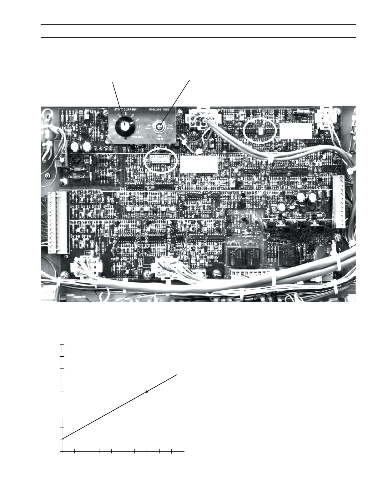
SECTION 4 OPERATION
90%
80%
70%
60%
50%
40%
30%
20%
10%
0%
0 1 2 3 4 5 6 7
8 9 10
4.4.4 Arc Initiation Controls
Start Current Potentiometer
UP-Slope Timer
SW1
SW2
4.4.5 Start Current and Up-Slope Timer
Starting Current (%) and Pot Setting Relationship
Start Current
Set using potentiometer located above and to the left of center
of PCB1. Factory default setting of 7 results in a starting current
that is 50% of the cutting current..
Up-Slope Timer
Three position switch located next to the start current potentiometer. Time is from start current (after dwell ends) to full
current. Factory default = 800 msec.
Left position = 250 msec
Center position = 800 msec
Right Position = 1200 msec
Percentage (%) of Cutting Current
MAX
Start Current Pot Setting
39

SECTION 4 OPERATION
4.4.6 Approximate EPP-601 V-I Curves for all models
Output Voltage (Volts)
0 100 200 300 400 500 600 700
0
50
V
REF
100
= 3.50V Min. Cutting Low Range
V
REF
= 5.00V Low Range
150
V
REF
V
= 0.625V High Range Min. Current
REF
V
= 10.00V Max. Low Range
REF
V
= 2.000V
REF
V
= 3.000V
REF
200
250
= 1.00V Min. Marking Low Range
V
= 1.000V High Range
REF
300
350
400
Output of Boost / Start Circuit (O in Marking Mode)
450
431V Open Circuit
Output Current (Amperes)
V
= 4.000V
REF
V
= 5.000V
REF
V
= 6.000V
REF
V
= 7.000V
REF
.
V
= 7.50 0 V
REF
Max Rating
Internal Current Limit
40
MAX RATING
DATA PL ATE
I
Max. Output Voltage
@Nominal Line
OUT
= (80) x (V
REF
)

SECTION 5 MAINTENANCE
ELECTRIC SHOCK CAN KILL!
WARNING
WARNING
CAUTION
5.1 General
5.2 Cleaning
SHUT OFF POWER AT THE LINE WALL DISCONNECT BEFORE AT
TEMPTING ANY MAINTENANCE.
EYE HAZARD WHEN USING COMPRESSED AIR TO CLEAN.
• Wear approved eye protection with side shields when cleaning the
power source.
• Use only low pressure air.
Maintenance On This Equipment Should Only Be Performed By
Trained Personnel.
Regularly scheduled cleaning of the power source is required to help keep the unit running trouble free. The frequency of
cleaning depends on environment and use.
1. Turn power o at wall disconnect.
2. Remove side panels.
3. Use low pressure compressed dry air, remove dust from all air passages and components. Pay particular attention to
heat sinks in the front of the unit. Dust insulates, reducing heat dissipation. Be sure to wear eye protection.
41

SECTION 5 MAINTENANCE
Air restrictions may cause EPP-601 to over heat.
Thermal Switches may be activated causing interruption of func-
CAUTION
5.3 Lubrication
• Some units are equipped with oil tubes on the fans. These fans should be oiled after 1 year of service.
• All other EPP-601s have fan motors that are permanently lubricated and require no regular maintenance.
WARNING
tion.
Do not use air lters on this unit.
Keep air passages clear of dust and other obstructions.
ELECTRIC SHOCK HAZARD!
BE SURE TO REPLACE ANY COVERS REMOVED DURING CLEANING
BEFORE TURNING POWER BACK ON.
42

SECTION 6 TROUBLESHOOTING
ELECTRIC SHOCK CAN KILL!
DO NOT PERMIT UNTRAINE D PERSONS TO INSPECT OR REPAI R THIS
WARNING
CAUTION
6.1 General
6.2 Fault Indicators
EQUIPMENT. ELECTRIC AL WORK MUST BE PERFORM ED BY AN EXPE
RIENCED ELECTRICIAN.
Stop work immediately if power source does not work properly.
Have only trained personnel investigate the cause.
Use only recommended replacement parts.
Front Panel Fault
Indicators
Fault indicators are found on the front panel Used with
the LEDs on PCB1 (located behind the cover with the
EPP label) problems can be diagnosed.
PCB1 Located behind
this panel.
NOTE:
It is normal for momentary lighting (ashing) of the fault indicator
and LED 3 when a “contactor on”
signal is applied at the beginning
of each cut start.
Fault Indicator used with:
LED 3 - Bus Ripple
LED 4 - High Bus
LED 5 - Low Bus
LED 7 - Arc Voltage Saturation
LED 8 - Arc Voltage Cuto
Power Reset Fault Indicator used with:
LED 6 - Right Overcurrent
LED 9 - Left Overcurrent
LED 10 - Left IGBT Unsaturated
LED 11 - Right IGBT Unsaturated
LED 12 - Left -12V Bias Supply
LED 13 - Right -12V Bias Supply
43

SECTION 6 TROUBLESHOOTING
Fault Indicator (Front Panel)
Illuminates when there are abnormalities in the cutting process or when the input
voltage falls ±10% outside the normal value. Momentary illumination is normal. If
continuously lit, check LEDs 3, 4, 5, 7, and 8 on PCB1 for further diagnosis.
LED 3 – (yellow) Bus Ripple Fault - Momentarily illuminates at the beginning
of each cut. Continuously lit during single-phasing or imbalanced line-to-line
voltages of the three phase input line (Excessive Ripple). Power Source is shut
down.
LED 4 – (yellow) High Bus Fault – Illuminates when input line voltage is too high
for proper operation (approximately 20% above nominal line voltage rating).
Power source is shut down.
LED 5 – (yellow) Low Bus Fault – Illuminates when input line
voltage is lower than 10% below nominal line voltage rating.
Power Source is shut down.
LED 7 – (yellow) Arc Voltage Saturation Fault – Illuminates
when the cutting arc voltage is too high and cutting current
drops below preset level. LED will extinguish after voltage
decreases and current rises.
LED 8 – (yellow) Arc Voltage Cuto Fault – Illuminates when arc
voltage increases over the preset value. PS is shut down.
44

SECTION 6 TROUBLESHOOTING
Power Reset Fault Indicator (on front panel)
Illuminates when a serious fault is detected. Input power must be disconnected for a
least 5 seconds to clear this fault. Check PCB1 Red LEDs 6, 9, 10, 11, 12, and 13 if this
fault is illuminated for further diagnosis.
LED 6 – (red) Right Overcurrent Fault – Illuminates when the current out of the right
side chopper is too high (400 amps). This current is measured by the right-side hall
sensor. The power source is shut down.
LED 9 – (red) Left Overcurrent Fault – Illuminates when the current from the left side
chopper is too high (400 amps). Measured by the left hall sensor. Power source is
shut down.
LED 10 _ (red) Left IGBT Unsaturated Fault – Illuminates when left IGBT is not fully
conducting. PS (PS) is shut down.
LED 11 – (red) Right IGBT Unsaturated Fault – Illuminates
when right IGBT is not fully conducting. Power Source (PS)
is shut down.
LED 12 – (red) Left -(neg) 12V Bias Supply Fault – Illuminates
when negative 12 V bias supply to the left side IGBT gate
drive circuit (located on PWM-drive board PCB2) is missing.
PS is shut down.
LED 13 – (red) Right –(neg) 12V Bias Supply Fault - Illuminates when negative 12 V bias
supply to the right side IGBT gate drive circuit (located on PWM drive board PCB3) is
missing. PS is shut down.
45

SECTION 6 TROUBLESHOOTING
6.3 Fault Isolation
Many of the most common problems are listed by symptom.
6.3.1 No output with contactor signal applied
6.3.2 Output limited to 100A
6.3.3 Fans not working
6.3.4 Power not on or low voltage
6.3.5 Fault light illumination
6.3.6 Torch won’t re
6.3.7 Fusses blown - F1 and F2
6.3.8 Intermittent, interrupted or partial operation
6.3.1 No output with contactor signal applied
Problem Possible Cause Action
External emergency stop (E-stop) is
Contactor signal is applied,
contactor lamp on front
panel is illuminated, K2 and
K3 contactors do not close
and low bus fault light, LED
5 illuminates.
open.
E-stop button on front panel is pushed
in.
Power reset lamp on front panel indi-
cates a serious fault condition.
6.3.2 Output limited to 100A
Problem Possible Cause Action
Power source will not go over
100A.
High current range signal missing.
6.3.3 Fans Not Working
Problem Possible Cause Action
Connect isolated contact of E-stop switch to provide connection between J1-E and J1-F.
Twist and pull out to reset E-stop condition.
Refer to section under fault light illumination.
External control should connect J1-R to J1-T. As
an alternative, in the power source, move the red
wire on TB8-1 to TB8-2.
All 4 fans do not run
1, 2 or 3 fans do not run.
This is normal when not cutting.
Fans run only when “Contactor On”
signal is received.
Broken or disconnected wire in fan
motor circuit.
Faulty fan(s) Replace fans
None
Repair wire.
46

SECTION 6 TROUBLESHOOTING
6.3.4 Power Not On or LOW Voltage
Problem Possible Cause Action
Power source inoperable:
Main power lamp is o.
Low open circuit voltage
Missing 3-phase input voltage
Missing 1 of 3-phase input voltage
Fuse F3/F4 blown Replace F3/F4
Pilot arc Contactor (K4) faulty Replace K4
Faulty Control PCB1 Replace Control PCB1 (P/N
6.3.5 Fault Light Illumination
Problem Possible Cause Action
Fault light illuminates at the end of
cut but goes o at the start of the
next.
LED 3 – (amber) Bus Ripple
LED 4 – (amber) High Bus
LED 5 – (amber) Low Bus
Restore all 3 phases of input voltage to within
±10% of nominal line.
Restore all 3 phases of input voltage to within
±10% of nominal line.
0558038313
Normal condition caused when terminating the arc by running the torch
o the work or the arc being attached
to a part that falls away.
Imbalance of 3-phase input power
Momentary loss of one phase of
input power
Faulty control PCB1 Replace PCB1 P/N
One or more phases of input voltage
exceed nominal line voltage by more
than 15%.
Faulty control PCB1 Replace PCB1 P/N
One or more shorted diode rectiers
(D25-D28) on the “Electrode Plate”
One or more phases of input volt-
age are lower than nominal by more
than 15%.
Blown F1 and F2 fuses
Over temp Light comes on. See over temp in Fault Light Section
Imbalanced 3-phase input
power
Momentary loss of one phase of
input power
Faulty Main Contactor (K1) Replace K1
FAULTY Control PCB1 Replace PCB1 P/N
Reprogram cutting process to
ensure arc is terminated only by
removing the “Contactor On” signal.
Maintain phase voltage imbalance
of less than 5%.
Restore and maintain input power
within ±10% nominal
0558038313
Restore and maintain line voltage
within ±10%
0558038313
Replace shorted diode rectiers
Restore and maintain within
±10% of nominal
See F1 and F2 in Blown
Fuses Section
Maintain phase voltage imbalance
of less than 5%
Restore and maintain within
±10% of nominal
0558038313
)
47

SECTION 6 TROUBLESHOOTING
Problem Possible Cause Action
LED 6 – (red) Right Over Current
Note:
If operation at 400A or less is
possible, then the LEFT side is
not working.
LED 9 – (red) Left Over Current
Note:
If operation at 400A or less is
possible, then the Right side is
not working.
Cutting at over 400A with a faulty left side
(left side output = 0)
Right current transducer connector loose
or unplugged. PCB loose.
Loose or unplugged connector at right
PWM/Drive Printed circuit board.
P2 at left of PWM / Drive PCB loose or unplugged.
Check voltage between P7-6 and P7-7. A
voltage in either polarity of greater than
0.01 V indicates a faulty right current transducer (TD2).
Faulty PCB1 Replace PCB1 P/N
Faulty right PWM / Drive PCB
Cutting at over 400A with a faulty right side
(right side output = 0)
Left current transducer connector loose or
unplugged. PCB loose.
Loose or unplugged connector at left PWM
/ Drive Printed circuit board.
P2 at right of PWM / Drive PCB loose or
unplugged.
Check voltage between P7-2 and P7-3. A
voltage in either polarity of greater than
0.01 V indicates a faulty left current transducer (TD1).
Faulty PCB1 Replace PCB1 P/N
Faulty left PWM / Drive PCB
See faulty left or right side
Secure connections
Secure connection
Secure connection
Replace right current transducer
(TD2)
Replace right PWM / Drive PCB P/N
0558038324
See faulty right side
Secure connections
Secure connection
Secure connection
Replace left current transducer (TD1)
Replace left PWM / Drive PCB P/N
0558038324
0558038313
0558038313
CAUTION
NEVER attempt to power-up or operate the power source with any
Gate / Emitter IGBT Plug disconnected from it’s PWM / Gate Drive
Board. Attempting to operate the power source with any open (unplugged) IGBT Gate / Emitter Connector may damage the IGBT and
the plasma cutting torch.
48

SECTION 6 TROUBLESHOOTING
Problem Possible Cause Action
Shorted IGBT Replace the IGBTs
Very high Output current accompanied by either a left or
right over current (LED 6)
LED 10 - (red) Left IGBT Unsaturated
LED 11 - (red) Right IGBT
Unsaturated
Current pot set too high Lower the current setting
Faulty left PWM / Drive PCB Replace left PWM / Drive PCB
High remote current signal Decrease remote current signal
Faulty PCB1 Replace PCB1 P/N 0558038313
Black wire connecting IGBT (Q2) collector to P3 of the
left PWM / Drive PCB (PCB2) is disconnected.
Shorted Freewheeling Diode(s) Replace freewheeling diode(s)
Loose or unplugged P1 connector at the left PWM /
Drive PCB
Loose or unplugged P10 connector at PCB1 Secure P10
Faulty PCB1 Replace PCB1 P/N 0558038313
Faulty left PWM / Drive PCB Replace PCB2 P/N 0558038324
Black wire connecting IGBT (Q5) collector to P3 of the
right PWM / Drive PCB (PCB3) is disconnected.
Shorted Freewheeling Diode(s) Replace freewheeling diode(s)
Loose or unplugged P1 connector at the left PWM /
Drive PCB
Loose or unplugged P10 connector at PCB1 Secure P11
Faulty PCB1 Replace PCB1 P/N 0558038313
Faulty right PWM / Drive PCB Replace PCB3 P/N 0558038324
Secure connector
Secure P1
Secure connector
Secure P1
49

SECTION 6 TROUBLESHOOTING
Problem Possible Cause Action
LED 12 – (red) Left –12V Missing
LED 13 – (red) Right –12V Missing
Very high Output current accompanied by either a left or right over current (LED 9 or LED 6 respectively)
Over Temp Lamp illuminates
Loose or unplugged P1 connector at
the left PWM / Drive PCB
Loose or unplugged P10 connector
at PCB1
Faulty left PWM / Drive PCB
Loose or unplugged P1 connector at
the right PWM / Drive PCB
Loose or unplugged P11 connector
at PCB1
Faulty right PWM / Drive PCB
Shorted IGBT Replace the IGBTs
Current pot set too high Lower the current setting
Faulty left PWM / Drive PCB
High remote current signal Decrease remote current signal
Faulty PCB1 Replace PCB1 P/N 0558038313
One or more fans inoperable Repair or replace fan(s)
Broken wire or unplugged connector
at thermal switch.
Obstruction to air ow closer than 3 feet
(1 m) to rear of power source.
Excessive dirt restricting cooling air
ow
Obstructed air intake
Secure P1 connector
Secure P10 connector
Replace left PWM / Drive PCB P/N
0558038324
Secure P1 connector
Secure P11 connector
Replace right PWM / Drive PCB P/N
0558038324
Replace left PWM / Drive PCB P/N
0558038324
Repair broken wires and unplugged connector
Allow 3 ft. (1 m) minimum between the rear
of the power source and any object that may
restrict air ow.
Clean out excessive dirt, especially in the
extrusions for the IGBTs and freewheeling
diodes, the POS, NEG and Electrode Plates,
the main transformer (T1) and the lter
inductors (L1 and L2).
Check and clear any obstructions from the
bottom, front, and top rear of the Power
Source.
50

SECTION 6 TROUBLESHOOTING
6.3.6 Torch Will Not Fire
Problem Possible Cause Action
Remote control removes the start signal
when the main arc transfers to the work.
Panel/Remote switch in “Remote” with
no remote control of the current
Place Panel/Remote switch in “Panel”
position
Main Arc Transfers to the work with a
short “pop”, placing only a small dimple
in the work.
Arc does not start. There is no arc at the
torch. Open circuit voltage is OK.
Remote current control present but
signal missing.
Current pot set too low. Increase current pot setting.
Start current pot, located behind the
cover for the control PCB is set too low.
Current up-slope controlled by external
control and power source is set for soft
start.
Open connection between the power
source positive output and the work.
Fuse F6 in the Pilot arc circuit is blown. Replace F6
Fuse F7 in the pilot arc circuit is blown. Replace F7
Pilot arc High/Low switch is in the ”LOW”
position when using consumables for
100A or higher (Refer to process data
included in torch manuals)
Pilot arc contactor (K4) faulty. Replace K4
Faulty PCB1
Check for current reference signal at TB14(+) and TB1-5(-). See Signal vs. Output
Current Curve this section.
Increase the start current post setting
to “7”.
Set power source for start by placing
SW1, positions 1 & 2, on control board
in o position. See section 4.4.
Repair connection
Change Pilot arc to “High” position.
(Refer to process data included in torch
manuals)
Replace PCB1 P/N
0558038312
51

SECTION 6 TROUBLESHOOTING
6.3.7 Fuses F1 and F2 Blown
Problem Possible Cause Action
Process controller must allow at least
Fuses F1 and F2 blown.
Process controller ignites pilot arc too
soon after providing the “Contactor
On” signal
Faulty negative (Electrode) output cable
shorting to earth ground.
Shorted freewheeling diode.
One or more shorted diode rectiers
(D13-D18) on “POS Plate”.
One or more shorted diode rectiers
(D7-D12) on “NEG Plate”.
300MS to lapse between the application of the “Contactor On” signal and
the ignition of the pilot arc. Fix process
controller logic and replace diodes.
Repair cable
Replace shorted freewheeling diode
and F1-F2
Replace all diode rectiers on the “POS
P la te”.
Replace all diode rectiers on the “NEG
P la te”.
6.3.8 Intermittent, Interrupted or Partial Operation
Problem Possible Cause Action
Loose or unplugged connector at left PWM /
Drive PCB (PCB2)
Works OK at 400A or less - Over
current right side when cutting
over 400A. LED 6 on control board
illuminated.
Works OK at 400A or less - Over
current left side when cutting
over 400A. LED 9 on control board
illuminated.
Faulty left PWM / Drive PCB
Check voltage between P5-1 and P5-2 at the
left PWM / Drive PCB (PCB2). Should be 20V
AC. Between P5-1 and P5-3 should be 40V AC.
If not the control transformer (T5) is faulty.
Loose or unplugged connector at Right PWM
/ Drive PCB (PCB3)
Faulty Right PWM / Drive PCB
Check voltage between P5-1 and P5-2 at the
right PWM / Drive PCB (PCB3). Should be 20V
AC. Between P5-1 and P5-3 should be 40V AC.
If not the control transformer (T7) is faulty.
Secure connector
Replace right PWM / Drive PCB P/N
0558038324
Replace control transformer T5
Secure connector
Replace right PWM / Drive PCB P/N
0558038324
Replace control transformer T7
CAUTION
NEVER attempt to power-up or operate the power source with any
Gate / Emitter IGBT Plug disconnected from it’s PWM / Gate Drive
Board. Attempting to operate the power source with any open (unplugged) IGBT Gate / Emitter Connector may damage the IGBT and
the plasma cutting torch.
52

SECTION 6 TROUBLESHOOTING
Problem Possible Cause Action
Power Supply turns o prematurely in the middle of the cut.
Problem Possible Cause Action
Output current is unstable and
drifts above or below the setting.
“Contactor On” signal is removed from unit.
Momentary loss of primary input power.
Faulty condition, indicated by illumination
of the fault lamp.
Faulty condition, indicated by the illumination
of the power reset fault lamp.
Current setting too low. Increase current setting
Remote current signal removed during cut. Fix remote current signal
Place the PANEL / REMOTE switch in the “PANEL”
position. Adjust current control pot. If current
no longer drifts, the remote current control
signal is faulty.
Select “PANEL” on the PANEL / REMOTE switch
and adjust the current control pot. The current still drifts, measure the current reference
signal at TB1-4 (+) and TB1-5 (-). If the signal
drifts, the current control pot is faulty. If the
signal does not drift, the Control PCB (PCB1)
is faulty.
Power source is OK. Trouble shoot process controller.
Restore and maintain input voltage
within ±10% of nominal.
Remove control PCB (PCB1) access panel
to determine the fault causing the shutdown. Refer to fault light illumination
section.
Remove control PCB (PCB1) access panel
to determine the fault causing the shutdown. Refer to fault light illumination
section.
Fix the remote current control signal.
Replace the current control pot.
Replace the control PCB (PCB1) P/N
0558038313
53

SECTION 6 TROUBLESHOOTING
6.4 Testing and Replacing Components
• Replace a PC board only when a problem is isolated to that board.
• Always disconnect power before removing or installing a PC board.
• Do not grasp or pull on board components.
• Always place a removed board on a static free surface.
NOTICE
Power Semiconductor Components
Categories of power semiconductors include;
• If a PC board is found to be a problem, check with your ESAB distributor for a replacement. Provide the distributor with the part number of
the board as well as the serial number of the power source.
• Do not attempt to repair the board yourself. Warranty will be voided if
repaired by the customer or an unauthorized repair shop.
• Power Rectiers
• Modules containing the free wheeling diodes and IGBTs
54

SECTION 6 TROUBLESHOOTING
6.4.1 Power Rectiers and Blocking Diodes
Power Rectiers
Power Rectiers
Procedure to access behind the front panel
1. Remove top cover and side panels
2. Locate and disconnect plug in rear of ammeter (attached
tone red and one black wire)
3. Remove pilot arc switch
4. Disconnect voltmeter
5. Disconnect orange and yellow wires from relay K4.
6. Remove two bolts holding the left side of the front panel
to the base.
7. Remove three bolts holding across the center base of the
front panel. These are accessed from underneath.
8. Remove one of the bolts holding the right side of the
front panel to the base. Loosen the second bolt. Of
these two bolts, remove the bolt on the left and loosen
the bold on the right.
9. Swing the front panel out to gain access to power recti-
Blocking Diodes
er components.
Troubleshooting Procedures –Negative Plate
Location of Neg. Plate
Location of fuses F8 and F9
1. Visually inspect fuses F8 and F9. Replace if they show signs
of being blown or melted. Inspect diodes. If ruptured
or burned, replace all diodes on the NEG Plate. If diodes
appear to be OK, proceed to next step.
55

SECTION 6 TROUBLESHOOTING
Diode RectierNEG Plate
1. Check ohms between NEG Plate and BR “A” Bus. A reading
of 2 ohms or less indicates one or more shorted diodes.
Replace all Diodes on NEG Plate.
2. If fuses F8 and/or F9 were open in the rst step, make two
more ohmmeter readings.
A. Measure resistance between the NEG Plate and
BR “B” bus.
Troubleshooting POS Plate
Location of Pos. Plate
Location of fuses F8 and F9
POS PlateElectrode Plate
B. Measure between NEG Plate and BR “C” bus.
If resistance is 2 ohms or less in either case, replace all the
diodes on the NEG Plate.
1. Check ohms between POS Plate and BR “A” Bus. A reading
of 2 ohms or less indicates one or more shorted diodes.
Replace all Diodes on POS Plate.
2. If fuses F8 and/or F9 were open in the rst step, make two
more ohmmeter readings.
A. Measure resistance between the POS Plate and BR
“B” bus.
B. Measure between POS Plate and BR “C” bus.
If resistance is 2 ohms or less in either case, replace all the
diodes on the POS Plate.
Troubleshooting Electrode Plate
Bus
Cathode Leads
Blocking Diodes D25, D26, D27 and D-28
1. Visually inspect for ruptured or burned diodes. Replace
only those damaged.
2. Check resistance between Electrode Plate and the parallel
pig tails (cathode leads) of D25 and D26. If reading is 2
ohms or less, disconnect leads from bus and check each
diode. Replace only shorted diodes.
Repeat procedure for D27 and D28. Replace only shorted
diodes.
56

SECTION 6 TROUBLESHOOTING
6.4.2 IGBT / Freewheeling Diode (FWD) Replacement
The emitter and the gate of each aected IGBT must be jum-
CAUTION
CAUTION
pered together to prevent electrostatic damage. Each power
source is supplied with six jumper plugs that mate to the IGBT
Gate / Emitter Plug.
Electrostatic Discharge Hazard
Electrostatic discharge may damage these components.
• Damage is accumulative and may only appear as shortened component life and not as a catastrophic failure.
• Wear a protective ground strap when handling to prevent damage
to PCB components.
• Always place a pc board in a static-free bag when not installed.
REMOVAL:
A. Insure that input power is removed by two actions such as a disconnect switch and removal of fuses. Tag and lock any
disconnect switch to prevent accidental activation.
B. Remove the top panel to gain access to the modules located in the top rear of the power source.
C. Clean the compartment containing the modules with dry, oil-free compressed air.
D. Unplug the gate drive leads connecting the IGBT Gates to the PWM/Gate Drive PC Board. In order to prevent damage
to the IGBT, install jumper plugs into the IGBT Gate Drive Connector. See Caution below. Jumper plugs are supplied
with each power source.
E. Remove the copper buss plates and bars connected to the IGBT’s. Save the M6 hardware connecting the bus structure
to the module terminals. You may need to re-use the hardware. Longer hardware can damage the module by contact-
ing the circuitry directly below the terminals.
F. Remove the M6 hardware mounting the modules to the heat sink. Save the hardware because you may need to re-use
it. Hardware too short can strip the threads in the Aluminum heat sink. Hardware too long can hit the bottom of the
holes causing the modules to have insucient thermal contact to the heat sink. Hardware too long or too short can
cause module damage due to over heating.
The module gate plugs must be plugged into the PWM/Gate
CAUTION
Drive PC Board whenever the power source is in operation.
Failure to plug them in will result in damage to the module and
possible damage to the torch.
57

SECTION 6 TROUBLESHOOTING
REPLACEMENT:
A. Thoroughly clean any thermal compound from the heat sink and the modules. Any foreign material trapped between
the module and heat sink, other than an appropriate thermal interface, can cause module damage due to over heating.
B. Inspect the thermal (interface) pad, P/N 951833, for damage. A crease or deformity can prevent the module from seat-
ing properly, impeding the heat transfer from the module to the heat sink. The result can be module damage due to
over heating.
If a thermal pad is not available, a heat sink compound such as Dow Corning® 340 Heat Sink Compound may be used. It’s
a good idea to mount all paralleled modules located on the same heat sink using the same thermal interface. Dierent
interfaces can cause the modules to operate at dierent temperatures resulting in un-equal current sharing. The imbalance can shorten module life.
C. Place a thermal pad, and an IGBT module on the heat sink. Carefully align the holes in the thermal pad with the heat-
sink and module holes. If heat sink compound is used in place of a thermal pad, apply a thin coat of even thickness to
the metal bottom of the module. A thickness of 0.002” – 0.003” (0.050mm – 0.075mm) is optimum. Too much compound impedes heat transfer from the module to the heat sink resulting in short module life due to over heating.
D. Insert the four M6 mounting bolts, but do not tighten. Leave them loose a few turns. Be certain that the threads from
the mounting bolts do not bend the edges of the thermal pad clearance holes. A bent thermal pad can prevent the
module from seating properly, impeding the heat transfer from the module to the heat sink. The result can be module
damage due to over heating.
E. Partially tighten the four mounting bolts a little more than nger tight in the order: A-B-C-D. See gure below.
F. Fully tighten, in the same order above, to a torque of 35 – 44 in-lbs (4.0 – 5.0 N-M). See gure below.
G. Install the bus plates and bus bars. Be careful that the sheets of insulation separating the bus plates are still in their
original positions. It’s a good idea to tighten the mounting hardware only after getting it all started. Torque the M6
module terminal hardware to 35 – 44 in-lbs (4.0 – 5.0 N-M).
H. Remove the jumper plugs from the module gate lead plugs, and plug into the appropriate plugs from the PWM/Gate
Drive PC Board. See Caution below.
I. Replace the top panel.
CAUTION
1 - IBGT Collector, Free Wheeling
Diode (FWD) Anode
2 - IGBT Emitter
3 - FWD Cathode
6 - IGBT Gate
7 - IGBT Emitter
The module gate plugs must be plugged into the PWM/Gate
Drive PC Board whenever the power source is in operation.
Failure to plug them in will result in damage to the module and
possible damage to the torch.
Four-Point Mounting Type
Partial tightening - A
A
D
Fully tightening - A
1
2
58
-B-C-D
-B-C-D
C
Key Plug
B
6 (RED)
3
7 (WHT)
Position 1 (RED)

SECTION 6 TROUBLESHOOTING
6.4.3 Power Shunt Installation
Instability or oscillation in cutting current can be caused by improper dressing of shunt pick-up leads.
CAUTION
Poor torch consumable life will be the result.
There are two cables that attach to the shunt pick-up points:
a two conductor cable drives the ammeter
a three conductor which provides the current feedback signal to PCB1 (control PCB).
Dressing of the 2 conductor cable is not critical.
The following is the dressing procedure for the 3 conductor cable.
• The breakout point should be physically at the middle of the shunt. The breakout point is the place
where the conductors exit from the outer insulation jacket.
• The black and clear insulated wires must be kept next to the shunt and under the cable ties.
• The wire terminals for the black and clear insulated wires should be oriented in parallel with bus bars
as shown.
three leads
Terminals parallel
to bus bars
clear insulation
• It is important to have the barrels of the black
and clear insulated wires, from the three lead
cable, be pointing in opposite directions.
• The third wire attaches to the bus bar on the left
with the shunt mounting hardware. Orientation
of this wire is not critical.
two leads
59

SECTION 6 TROUBLESHOOTING
6.4.4 Procedure For Verifying Calibration Of Digital Meters.
Voltmeter
1. Connect a digital meter known to be calibrated to the positive and negative output bus bars.
2. Compare the power source voltmeter reading to the calibrated meter reading. Readings should match within
±0.75%.
Ammeter
1. External to the power source, connect a precision shunt in series with the work lead(s). The best shunt is one with a
value of 100 micro-ohms (50mV / 500A or 100mV / 1000A) and a calibrated tolerance of 0.25%.
2. Use a calibrated 4 ½ digit meter to measure the output of the shunt. The amperage indicated with the external shunt
and meter should match power source ammeter to within 0.75%.
6.5 Control Circuit Interface Using J1, J4 and J6 Connectors
Interface to the EPP-601 control circuitry is made with connectors J1, J4 and J6 on the front panel. J1 has 24 conductors, J4
has 2 and J6 has 10.
J1-P and J1-G provide access to the galvanically isolated transistor output signal indicating an “Arc On” condition. See
Subsection 6.8, Arc Current Detector Circuits. J1-L and J1-J are the inputs for the remote Voltage Reference Signal that
commands the EPP-601 output current Subsection 6.9, Current Control Pot & Remote Vref. J1-R and J1-Z supply 115V AC for
remote controls. See Subsection 6.6, Auxiliary Main Contactor (K3 and K33) & Solid State Contactor Circuits and Subsection
6.10, Pilot Arc Hi/lo & Cut/mark Circuits.
J1-E and J1-F are the input connections for the Emergency Stop function. For Emergency Stop to operate, the Jumper
between TB8-18 and TB8-19 must be removed.
J1-S is the input to K8 that parallels S1 switch contact. When 115V AC from J1-R is fed into J1-S, K8 activates placing the Pilot
Arc in High.
J4-A and J4-B are from an isolated contact on the emergency stop (E-stop) switch. This signal can be used by the plasma
control to indicate the state of the E-stop switch on the power source.
Cut / Mark selection: The power source defaults to Cutting mode when there is no signal fed into J1-C. When 115V AC from
J1-R is fed into J1-C, K11 is activated placing the EPP-601 in the Marking mode. For more details concerning the operation
of K11 and the Cut / Mark modes, refer to Subsection 6.10, High / Low Cut Current Modes and Mark Mode.
High / Low current ranges: The power source defaults to low cutting current range (35-100A) when no signal is fed into
J1-T. High range (50A to maximum current rating) is selected whenever 115VAC is fed into J1-T by connecting J1-R to J1-T.
J6 connects to the water cooler. J6-A and J6-B are 115VAC hot and neutral respectively. This 115VAC activates the contactor for the pump. J6-C and J6-D connect to the ow switch. The ow switch is closed when coolant is owing. J6-E and
J6-H connect to the coolant level switch. The switch is closed when the coolant reservoir contains sucient coolant and
it is open when the reservoir is low.
60

SECTION 6 TROUBLESHOOTING
CONTROL CIRCUIT INTERFACE USING J1, J4, & J6 CONNECTORS
EPP-450 POWER SOURCE
CONTROL
REMOTE EMERGENCY STOP
ISOLATED CONTACT
E-STOP LOOP MUST BE
CLOSED FOR POWER
SOURCE TO FUNCTION
PILOT ARC HI/LO
PLASMA START
CUT/MARK MODE SELECT
HI/LO CURRENT RANGE
CUT/MARK
CURRENT DETECT
REMOTE
0 - 10V Vref
-
CUT
MARK
LO
HI
COOLANT LEVEL
COOLANT FLOW
15 - 50 VDC
+
-
+
J4-A
J4-B
J1-F
RED 06
J1-E
RED 05
J1-D
GRN/YEL
J1-Z
RED 04
J1-R
RED 16
J1-S
RED 17
J1-M
RED 12
J1-C
RED 03
J1-T
RED 18
J1-K
RED 10
J1-B
RED 02
J1-G
RED 07
J1-P
RED 14
J1-Y
RED 23
J1-L
RED 11
J1-J
RED 09
TB8-19
TB8-18
K11
115 VAC HI
RANGE
INPUT
EPP-601 POWER SOURCE
ISOLATED CONTACT
22
E-STOP RELAY
K15
115V AC NEUTRAL
115V AC HOT
S1
LO
HI
115V AC CONTACTOR INPUT
115V AC MARK MODE INPUT
K13 K14
H
100V
50mA
MAX
10 OHMS
100 OHMS
ELECTRODE CURRENT SIGNAL 1.0V = 100A
+
-
S5
24 VAC
T2
CHASSIS
H
OFF: PILOT ARC LOW
ON: PILOT ARC HIGH
IN MARK MODE, K11 FORCES
THE LO CURRENT RANGE
115 VAC
CURRENT
DETECTOR
200K
Ohms
21
E-STOP BUTTON
1112
3A
CB2
T2
115 VAC
NOTE: Panel S1
MUST BE in LOW
position for remote
contact to function
K8
K3
K33
K11
J6-B
J1-B
CONTACTOR FOR
J6-A
J1-A
J6-H
J1-H
J6-C
J1-C
J6-D
J1-D
J6-E
J1-E
REMOTE CUTTING CURRENT
REFERENCE VOLTAGE (Vref)
Icut = (Vref) x (80)
PUMP & FAN
FLOW
SWITCH
COOLANT CIRCULATOR
OK
LEVEL
SWITCH
OK
LO
K1
LO
61

SECTION 6 TROUBLESHOOTING
N
115V
AC
H
J6-BJ1-ZJ1-R
TB1-7
TB8-7
J1-D
TB1-8
115V AC
9
TB9-18
TB9-13
TB9-16
K33 K15
6 69
R45B
TB7-8
TB7-9
P6-1
TB1-9
K3
K2
K4
P2-5 P2-6
K33
P1-9 P1-10
680
P6-2
K3 K7
6 699
ON/OFF
IGBT DRIVE
ON/OFF
LED3 LED3
LEFT PWM/GATE
DRIVE PC BOARD
RIGHT PWM/GATE
DRIVE PC BOARD
+15V
CONTROL
PC BOARD
Solid State Contactor
T
(AMC)
K6
96
NEUTRAL
HOT
I
FN4
J1-E
4
12
STARTING
CONTACTOR
PILOT ARC
CONTACTOR
3
Current Detector
Contact on
Control PCB
Fault Relay
IGBT DRIVE
AUXILLARY MAIN CONTACTOR (K3 & K33)
& SOLID STATE CONTACTOR CIRCUITS
Open with fault and main line power off
Over Heat Relay - Closed
during normal operation
R45A
8W
10K
P1-9 P1-10
TB7-8
P10-5
P10-6
P11-5
P11-6
8W
10K
K15
8
5
E-STOP
RELAY
E-STOP
RELAY
J6-A
6.6 Auxiliary Main Contactor (K3 & K33) and Solid State Contactor Circuits
K3 and K33, activated by supplying a Contactor Signal, initiate and controls the operation of K2 (Starting Contactor) and
K4 (Pilot Arc Contactor). K3/K33 are called the Auxiliary Main Contactors because they must be activated before the
Main Contactor (K1) power-up sequence can occur. The Contactor Signal is supplied through a remote contact connecting 115VAC from J1-R to J1-M. If K6 is closed (no fault), K3 will activate. The closing of K3(6, 9) activates K2, the Starting
Contactor, and K4, the Pilot Arc Contactor, provided the power source is not over heated. See Subsection 6.7, E-stop and
Main Contactor Circuits for more information on the operation of K2. K4 is turned o when the Current Detector senses arc
current and opens the contact connecting P2-5 to P2-6 on the Control PC Board.
In addition to operating K3/K33, the Contactor Signal also activates the Solid State Contactor. The Solid State Contactor is
a logic and interlock circuit permitting the IGBT’s to conduct whenever the remote Contactor Signal is present. The 115V
AC Contactor Signal is fed to TB1-9, TB7-8, and resistors R45 and R45-A. These resistors reduce the 115V to approximately
16V AC fed into the Control PC Board at P6-1 and P6-2. The Control PC Board sends a signal to both the Left and Right PWM
/ Gate Drive PC Boards. Illumination of LED3 on both of the PWM / Gate Drive PC Boards is indication that the Solid State
Contactor is functioning.
62

SECTION 6 TROUBLESHOOTING
6.7 E-Stop (Emergency Stop) and Main Contactor (K1A, K1B and K1C) Circuits
A power-up sequence takes place before the Main Contactor (K1) activates. K1 is actually three separate contactors – one
for each primary input phase. Thus, K1A, K1B, and K1C switch phases A, B, and C respectively to the Main Transformer, T1.
The power-up sequence begins with a remote Contactor Signal activating K3 and K33. Refer to the description entitled,
Section 6.6, Auxiliary Main Contactor (K3 and K33) & Solid State Contactor Circuits for more information. K3 and K33 activates K2 closing the three contacts of K2. K2 bypasses K1 contacts providing primary input power to the Main Transformer,
T1. This current is limited by three one Ohm resistors, R1, R2, and R3. The resistors eliminate the high surge currents typical
of the turn-on inrush transients associated with large transformers. The high current surge of charging the Bus Capacitor
Bank is also eliminated by initially powering the Main Transformer through K2 and the resistors.
The discharged Bus Capacitor Bank initially prevents the output of the Main transformer from reaching its normal value.
As the Bus Capacitor Bank charges, the Main Transformer output voltage rises and becomes high enough for K1A, K1B, and
K1C to close. Once the K1’s are closed, the contacts of the Starting Contactor, K2, are bypassed, and full primary line power
is supplied to the Main Transformer through the contacts of the K1’s.
Because the starting sequence takes time, it is important at least 300 mS lapse between applying the Contactor Signal
and applying load to the power source. Applying load too soon will prevent the K1’s from closing and fuses F1 and F2 will
open.
K15, the E-Stop relay must be closed for the power-up sequence to take place. K15 contains one contact in the K2 coil circuit
and another contact in the K1A, K1B, & K1C circuits. There is no power supplied to the Main Transformer, T1, until K15 is activated. For K15 to activate, S5, the E-Stop switch on the front panel must be closed. Also, the Plasma Control must complete
the E-stop loop by closing an isolated contact between J1-E and J1-F.
The E-Stop switch is closed whenever the E-Stop button, on the front panel, is pulled out. For troubleshooting purposes
only, a jumper can be connected between TB8-18 and TB8-19. If a jumper is installed, it MUST be removed before placing
the power source back into service. If the jumper is not removed, the power source E-Stop condition will not function when
the E-Stop button for the Plasma Control is pushed.
J4-A and J4-B are connected together whenever the E-Stop button on the power source is pulled out. This signal can be
sent to the Plasma Control so that the control senses the state of the power source E-Stop switch.
63

SECTION 6 TROUBLESHOOTING
E-STOP (EMERGENCY STOP) CIRCUIT
3 PHASE INPUT POWER
6.7 E-Stop (Emergency Stop) and Main Contactor (K1A, K1B and K1C) Circuits (continued)
TB4
K1A
R1
L1 L2 L3
T1 T2 T3
1
300W
L1
T1
TB5
15A
K1B K1C
F1
L1 L2 L3
T1 T2 T3
R2
1
300W
L2
T2
MAIN
TRANSFORMER
TB6
15A
(MC)(MC)(MC)
L1 L2 L3
T1 T2 T3
115 VAC WINDING ON
"A" COIL OF MAIN
TRANSFORMER
F2
L3
T3
(T1) ASSY
4
K3
7
4
K15
7
A
K1A
J6-A
J1-R
H
5
K15
8
K3
69
K7
69
115 VAC
STARTING
CONTACTOR
A
K2
K33
69
K15
N
69
R3
1
300W
K2K2K2
4
K7
7
4
K33
7
J4-A
J4-B
E-STOP RELAY
J1-E
TB8-19
TB8-18
J1-F
E-STOP
E-STOP LOOP MUST BE
CLOSED FOR POWER
SOURCE TO FUNCTION
A
22
S5
K15
F
TO T2-X3 TO CB2-2
21
E-STOP
BUTTON
12 11
24 VAC
64
A
K1B
A
K1C
M
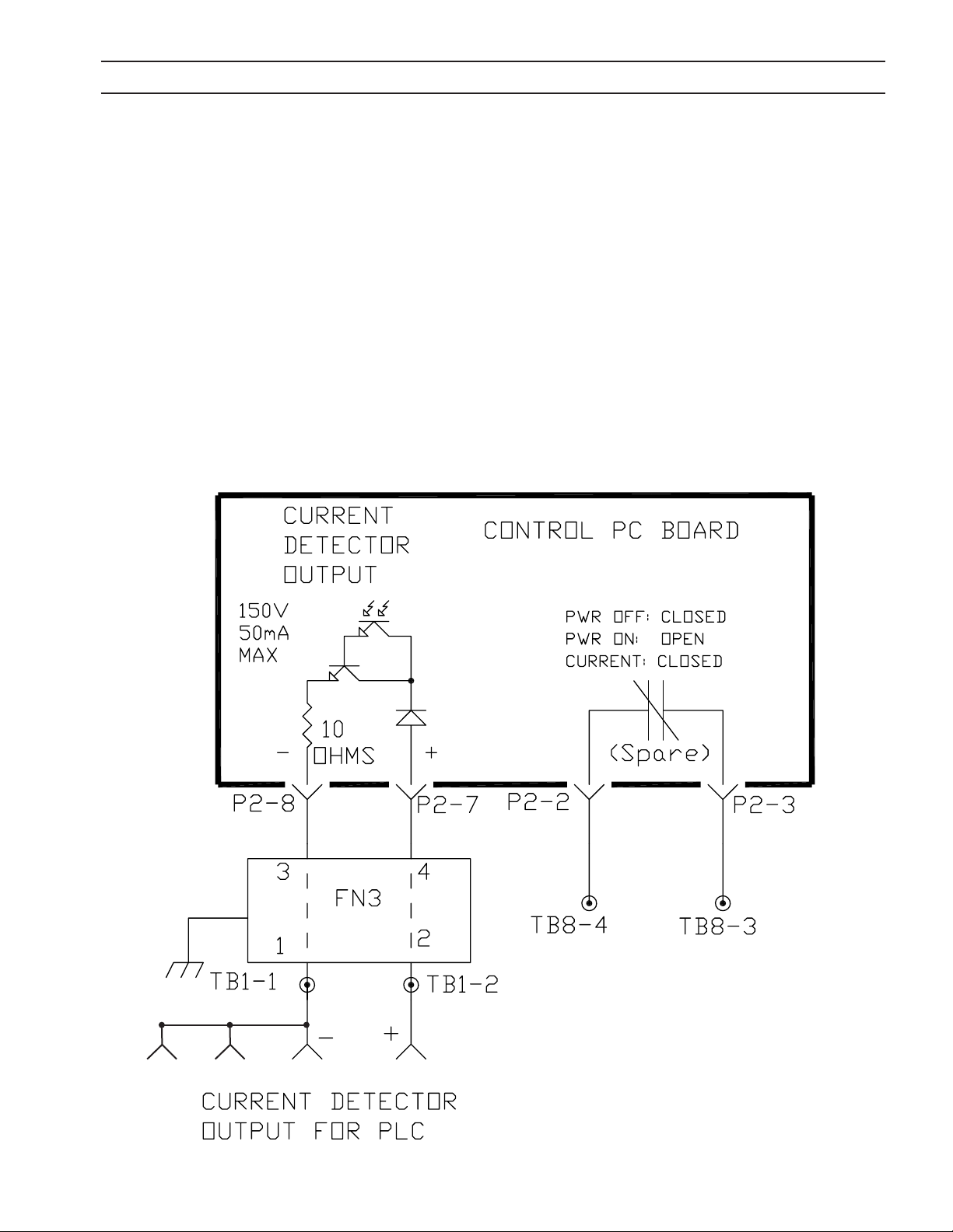
SECTION 6 TROUBLESHOOTING
6.8 Arc Current Detector Circuits
There are three Arc Current Detector circuits in the EPP-601. One is used internally to control the Pilot Arc Contactor, K4.
The other two are available for remote use.
A galvanically isolated transistor Current Detector Output is accessible at J1-G (-) and J1-P (+). J1 is the 24 conductor connector on the EPP-601 front panel. The transistor is best suited for switching small relays or low current logic signals like
those utilized by PLC’s (Programmable Logic Controllers). The transistor can withstand a maximum peak voltage of 150V.
It can switch a maximum of 50 mA. The transistor turns on whenever the arc current through the Work Lead exceeds 5A.
Pilot arcs not establishing main arcs will not turn on the transistor.
A second current detector output is available at TB8-3 and TB8-4. This output is supplied by an isolated relay contact rated
for 150V, 5 Amperes. This contact is closed when the primary input power to the EPP-601 is o. It opens whenever primary
power is supplied to the power source, and it closes when main arc current is established. Like the transistor output, the
relay contact closes whenever the arc current through the Work Lead exceeds 5A. Pilot arcs not establishing main arcs will
not close the contact.
J6-D J6-E J1-G J1-P
65

SECTION 6 TROUBLESHOOTING
6.9 Current Control Pot and Remote Vref
A Reference Voltage, V
, is used to command the output current of the EPP-601. V
REF
is a DC voltage that can come from
REF
either the Current Control Potentiometer on the front panel or from a remote source. In the “Panel” position, S2, the Panel
/ Remote switch selects the Current Control Potentiometer. In the “Remote” position, the Panel/Remote switch selects the
V
fed into J1-L (+) and J1-J (-). The EPP-601 Output Current, I
REF
I
= (80) x (V
OUT
) in the high output current mode and I
REF
OUT
, will follow V
OUT
= (10) x (V
with the following relationship:
REF
) in the low output current mode.
REF
PCB10 is the analog signal scaling board. If 115VAC is fed into P1-2 and P1-3 the output current range is in the high mode
used for cutting from 50 to 600A. With the 115VAC absent, the output current range is in the low mode used for marking
between 10 and 100A and cutting between 35 and 100A.
The Control PC Board contains two inputs for V
the High Speed input (P8-3), the EPP-601 will respond to a change in V
is fed into the Low Speed input (P8-1), the EPP-601 will respond to a change in V
: High Speed; and Normal. When the negative of the V
REF
within 10 mS. When the negative of the V
REF
within 50 mS. The slower response of
REF
signal is fed into
REF
signal
REF
the “Normal” input helps lter electrical noise sometimes encountered in industrial environments.
0.00-10.00V
CONTROL
BOARD
0558038313
JUMPER
CURRENT REFERENCE
EPP-600: I(out) = (80) X Vref
200K
-
HIGH
SPEED
P8-3
200K
NRM
-
P8-1
+10T
S
+
P8-2
PRECISION
REFERENCE
JUMPER FOR
EPP-600
P5-8 TB1-3
P4-10
P4-11
220
P4-12
S BIAS
P3-3 P3-5P3-4
PRI: 120V
SEC: 40VCT
H1 H2
H N
S
T10
120V
P4-9
220
+15S
20V20V
TB8-11
TB1-4
J1-L
S
REMOTE
REMOTE
C46
.01
+
P4-8
-
50
SIGNAL:
LO: 10V = 100A
HI EPP-600: 1V = 80A
P4-2
22
11
C45
0-10V
200K
200K
S2
3
3
.01
+
P4-7
50
S
NRM SPEED
P4-1
-+
55
PANEL
PANEL
TB1-5
J1-J
66
TB1-6
TB8-12
J1-J, DC SIGNAL
COMMON (NEG)
ALSO SHOWN
ON PAGE 1
4
4
-
P2-1 P2-2
PCB10
ANALOG
SCALING
BOARD
0558038326
HIGH
-
P4-3
115VAC = HIGH RANGE
P1-3 P1-2
D
N
CURRENT
CURRENT
CONTROL
CONTROL
POT
POT
R50
10K
T
SEE PAGE 1, K13-6
66

SECTION 6 TROUBLESHOOTING
HIGH/LOW CUT CURRENT MODES & MARK MODE
6.10 High / Low Cut Current Modes and Mark Mode
A remote contact connecting 115V AC from J1-R to J1-S places the Pilot Arc in High by operating K8. Note, that for this function to operate, the Pilot Arc Hi/Lo switch on the front panel must be in the “LO” position.
The EPP-601 is placed in the Marking mode when a remote contact connecting 115V AC from J1-R to J1-C operates K11. In
the Marking mode, a normally closed contact on K11 opens turning o K10. When K10 turns o, the Boost supply is disconnected lowering the normal Cutting Mode 430V DC Open Circuit Voltage to 360VDC for Marking. A normally open contact
on K11 activates K12. K12 connects the I (min) resistors necessary for stabilizing the low currents required for marking. In
the Cutting mode, the minimum stable output current is 50A in the high current range, 35A in the low current range and
10A in the marking mode. In the marking mode, the normally closed contacts K11(3, 9) and K11(1, 7) open. This deactivates
K13 and K14 placing the power source in the low current range.
115 VAC
K15
H
5
8
SEE PAGE 2
PCB10 P1-2
D
69
J6-A
E-STOP
RELAY
K13
9
K13
9
9
LO
S1
6
HI
Z BIAS
SEC 40VCT
3
K11
6
K11
3
5
P5-2P5-3
20V20V
PRI 120V
T7
5
K4
T3
PILOT ARC
HI/LO
N
P5-1
K3
L3
PCB3 Right
PWM/Gate Drive
10 2W
A
8
K12
A
K13
K8
58
FAN
M5
R70
I(min) RESISTORS
1µF
600V
WHT
K10
BOOST
N
TB9-18
TB9-13
3
4
FN4
12
115V
J1-M
AC
TB1-7
TB8-7
H
J1-R
TB1-7
CONTACTOR SIGNAL
J1-Z
TB1-8
N
J6-B
LO
PILOT
ARC MARK
J1-S
HI
CUT/
CUT
K11
A
J1-C
MARK
CUT
CURRENT
RANGE
67
LO
HI
K14
TB8-2
TB8-1
J1-T
K13
7
K11
1
RED
MOVE RED WIRE
FROM TB8-1 TO
TB8-2 FOR FOR HI
CURRENT RANGE

SECTION 6 TROUBLESHOOTING
ELECTRODE CURRENT TRANSDUCER CIRCUIT
6.11 Low Current Range
The EPP-601 operates in either LOW or HIGH current output ranges. The LOW range is used for marking from 10 to 100
amperes and cutting from 35 to 100 amperes. The HIGH range is used for cutting from 50 to 600 amperes.
In the HIGH range, both the left and right power sources are used. Each side contributes 50% of the total output current.
The left side acts as a master power source by synchronizing the switching of the right side to its own switching frequency
of 10 KHz.
In the LOW range, only the left power source is used. The normally open contact, K13(6, 9) prevents T7 from supplying bias
supply power to PCB-3, the right PWM / IGBT Gate Drive PC Board. This disables the right side.
The same K13 contact (square labeled “D” on the schematic diagrams) places the EPP-601 in the HIGH current mode. In
addition to providing bias power to PCB-3 in the HIGH current mode, this 115 VAC is fed into PCB-10 P1-2.
PCB-10 performs two functions. With no input on PCB-10 P1-2, PCB-10 scales the 0 to 10 VDC current reference signal for 0
to 100 amperes (LOW range). In the LOW range, PCB-10 P4-11 / P4-12 provides a signal to PCB-2 P4-1 / P4-2. This signal commands PCB-2, the left (master) PWM / IGBT Gate Drive PC Board to change the switching frequency from 10 KHz to 25 KHz.
The higher switching frequency results in the more power dissipation by the heat sinks on PCB-3. Therefore, in the LOW
current mode, a small fan, M5, turns on to provide additional cooling. M5 does not operate in the HIGH current mode.
6.12 Electrode Current Transducer Circuit
The Electrode Current Transducer Circuit provides a galvanically isolated signal to the plasma control indicating the power
source output current. The scaling of the signal is: VOUT = IELECTRODE/100. For example, 200A results in 2.0V output. The
scaling is the same for both high and low current ranges. The output signal resistance is 100 Ohms.
PCB11 receives the signal from the Hall Eect Transducer and sends the signal through FN5 to J1-Y (+) and J1-J (-). PCB11 supplies +15V and -15V to operate the transducer. It also buers the signal to prevent damage to the transducer from voltage
transients generated outside the power source.
J1-J
TB9-1
Vref COMMON
NOZZLE
(TB10)
JUMPER CONNECTS
Vref (-) AND OUTPUT
CURRENT SIGNAL (-)
TOGETHER
(POSITION FOR
PLASMA CUTTING)
TO SHUNT NEG.
TO PILOT ARC CONTACTOR, K4-T1
ELECTRODE
CURRENT
TRANSDUCER
TD3
HALL
ARROW
OUTPUT CURRENT SIGNAL COMMON
TB9-3
TB9-2
MOVING JUMPER SEPARATES
Vref COMMON & OUTPUT
CURRENT SIGNAL COMMON
P1-2
P1-4
P1-3
P1-1
J1-X
1.00V SIGNAL = 100A OUTPUT
P4-6
P4-5
P4-1
P4-2
+-
J1-Y
-15V
COMMON
SIGNAL -
SIGNAL +
1
2
FN5
PCB11
3
4
P4-7
50
OUTPUT
CURRENT
SIGNAL
-
+
50
ANALOG
SCALING
BOARD
P4-8
ELECTRODE
12
FN1
3
WORK
+
12
FN2
3
P4-4
68
+15V
P3-2
P3-1P1-2 P1-1
PRI: 120V
SEC: 40VCT
P3-3
P3-4
20V 20V
T11
H2
H1
P3-5
N
H

SECTION 7 REPLACEMENT PARTS
7.0 Replacement Parts
7.1 General
Always provide the serial number of the unit on which the parts will be used. The serial number is stamped on
the unit serial number plate.
7.2 Ordering
To ensure proper operation, it is recommended that only genuine ESAB parts and products be used with this
equipment. The use of non-ESAB parts may void your warranty.
Replacement parts may be ordered from your ESAB Distributor.
Be sure to indicate any special shipping instructions when ordering replacement parts.
Refer to the Communications Guide located on the back page of this manual for a list of customer service phone
numbers.
EPP-601 Input/Output Information
Part Number
EPP-601
380V 50/60HZ
380V TAPS
EPP-601
380V 50/60HZ
40 0V TAPS
0558007733 0558007734 0558007735
EPP-601
400V 50/60HZ
EPP-601
460V 60HZ
EPP-601
575V 60HZ
Note
Items listed in the following Bill of Materials that do not have a part number
shown are not available from ESAB as a replaceable item and cannot be
ordered. Descriptions are shown for reference only. Please use local retail
hardware outlets as a source for these items.
Note
Replacement Parts, Schematics and Wiring Diagrams are
printed on 279.4mm x 431.8mm (11” x 17”) paper and are
included inside the back cover of this manual.
69

NOTES

REVISION HISTORY
1. Original release - 12/2007
2. Revision 05/2008 - added E-stop information throughout manual. Included Replacement Parts
section in Schematic / Wiring Diagram package. Changed power supply name from EPP-600 to
EPP-601.
3. Revision 07/2010 - made various per P. Higgins in accordance with GE manual.
4. Revision 08/2010 - Updated with new DOC form.
5. Revision 05/2012 - minor editorial changes.
6. Revision 06/2012 - dimensions changes section 2.3.

ESAB Welding & Cutting Products, Florence, SC
COMMUNICATION GUIDE - CUSTOMER SERVICES
A. CUSTOMER SERVICE QUESTIONS:
Telephone: (800)362-7080 / Fax: (800) 634-7548 Hours: 8:00 AM to 7:00 PM EST
Order Entry Product Availability Pricing Order Information Returns
B. ENGINEERING SERVICE:
Telephone: (843) 664-4416 / Fax : (800) 446-5693 Hours: 7:30 AM to 5:00 PM EST
Warranty Returns Authorized Repair Stations Welding Equipment Troubleshooting
C. TECHNICAL SERVICE:
Telephone: (800) ESAB-123/ Fax: (843) 664-4452 Hours: 8:00 AM to 5:00 PM EST
Part Numbers Technical Applications Specications Equipment Recommendations
D. LITERATURE REQUESTS:
Telephone: (843) 664-5562 / Fax: (843) 664-5548 Hours: 7:30 AM to 4:00 PM EST
E. WELDING EQUIPMENT REPAIRS:
Telephone: (843) 664-4487 / Fax: (843) 664-5557 Hours: 7:30 AM to 3:30 PM EST
Repair Estimates Repair Status
F. WELDING EQUIPMENT TRAINING
Telephone: (843)664-4428 / Fax: (843) 679-5864 Hours: 7:30 AM to 4:00 PM EST
Training School Information and Registrations
G. WELDING PROCESS ASSISTANCE:
Telephone: (800) ESAB-123 Hours: 7:30 AM to 4:00 PM EST
H. TECHNICAL ASST. CONSUMABLES:
Telephone : (800) 933-7070 Hours: 7:30 AM to 5:00 PM EST
IF YOU DO NOT KNOW WHOM TO CALL
Telephone: (800) ESAB-123
Fax: (843) 664-4462
Hours: 7:30 AM to 5:00 PM EST
or
visit us on the web at http://www.esabna.com
The ESAB web site oers
Comprehensive Product Information
Material Safety Data Sheets
Warranty Registration
Instruction Literature Download Library
Distributor Locator
Global Company Information
Press Releases
Customer Feedback & Support
 Loading...