


Aristo®
Mig4004iPulse
Instruction manual
0463 380 031 US 20150929 Valid for: serial no. 419-xxx-xxxx, 528-xxx-xxxx

TABLE OF CONTENTS
1 SAFETY PRECAUTIONS ..................................................................................... 3
2 INTRODUCTION...................................................................................................9
2.1 Equipment............................................................................................................. 9
3 TECHNICAL DATA ............................................................................................ 10
4 INSTALLATION................................................................................................... 12
4.1 Location .............................................................................................................. 12
4.2 Lifting instruction............................................................................................... 12
4.3 Electrical supply................................................................................................. 12
5 OPERATION ....................................................................................................... 16
5.1 Connections and control devices..................................................................... 16
5.2 Symbols .............................................................................................................. 17
5.3 Connection of welding and return cable.......................................................... 17
5.4 Turning the power source on/off ......................................................................17
5.5 Fan control.......................................................................................................... 17
5.6 Overheating protection...................................................................................... 18
5.7 VRD (Voltage Reducing Device) .......................................................................18
5.8 Remote control unit ........................................................................................... 18
5.9 MIG/MAG and self-shielded cored wire welding .............................................18
6 MAINTENANCE..................................................................................................19
6.1 Inspection and cleaning .................................................................................... 19
6.2 Welding torch ..................................................................................................... 19
7 FAULT TRACING................................................................................................ 20
8 ORDERING SPARE PARTS ............................................................................... 21
DIAGRAM ..................................................................................................................22
ORDERING NUMBERS.............................................................................................23
SPARE PARTS LIST.................................................................................................. 24
ACCESSORIES .........................................................................................................25
Rights reserved to alter specifications without notice.
0463 380 031 © ESAB AB 2015

1 SAFETY PRECAUTIONS
1 SAFETY PRECAUTIONS
NOTE!
Be sure this information reaches the operator. You can obtain extra copies via
your supplier.
CAUTION!
These INSTRUCTIONS are for experienced operators. If you are not fully familiar
with the principles of operation and safe practices for arc welding equipment, we
urge you to read our booklet, "Precautions and Safe Practices for Arc, Cutting
and Gouging", Form 52-529 . Do NOT permit untrained persons to install,
operate, or maintain this equipment. Do NOT attempt to install or operate this
equipment until you have read and fully understand these instructions. If you do
not fully understand these instructions, contact your supplier for further
information. Be sure to read the Safety Precautions before installing or operating
this equipment.
This equipment will perform in conformity with the description thereof contained in this
manual and accompanying labels and/or insert when installed, operated, maintained and
repaired in accordance with the instruction provided. This equipment must be checked
periodically. Malfunctioning or poorly maintained equipment should not be used. Parts that
are broken, missing, worn, distorted or contaminated should be replaced immediately. Should
such repair or replacement become necessary, the manufacturer recommends that a
telephone or written request for service advice be made to the Authorised Distributor from
whom it was purchased.
This equipment or any of its parts should not be altered without the prior written approval of
the manufacturer. The user of this equipment shall have the sole responsibility for any
malfunction which results from improper use, faulty maintenance, damage, improper repair or
alteration by anyone other than the manufacturer or a service facility designated by the
manufacturer.
CAUTION!
Read and understand the instruction manual before
installing or operating.
WARNING!
These Safety Precautions are for your protection. They summarise precautionary
information from the references listed in the Additional Safety Information section.
Before performing any installation or operating procedures, be sure to read and
follow the safety precautions listed below as well as all other manuals, material
safety data sheets, labels, etc. Failure to observe the Safety Precautions could
result in injury or death.
PROTECT YOURSELF AND OTHERS
Some welding, cutting and gouging processes are noisy and require
hearing protection. The arc, like the sun, emits ultraviolet (UV) and
other radiation and can injure the skin and eyes. Hot metal can cause
burns. Training in the proper use of the processes and equipment is
essential to prevent accidents. Therefore:
0463 380 031
- 3 -
© ESAB AB 2015

1 SAFETY PRECAUTIONS
1. Always wear safety glasses with side shields in any work area, even if welding helmets,
face shields and goggles are also required.
2. Use a face shield fitted with the correct filter and cover plates to protect your eyes, face,
neck and ears from sparks and rays of the arc when operating or observing operations.
Warn bystanders not to look at the arc and not to expose themselves to the rays of the
electric-arc or hot metal.
3. Wear flameproof gauntlet type gloves, heavy long-sleeve shirt, cuffless trousers,
high-topped shoes and a welding helmet or cap for protection, to protect against arc rays
and hot sparks or hot metal. A flameproof apron may also be desirable as protection
against radiated heat and sparks.
4. Hot sparks or metal can lodge in rolled up sleeves, trouser cuffs, or pockets. Sleeves and
collars should be kept buttoned and open pockets eliminated from the front of the
clothing.
5. Protect other personnel from arc rays and hot sparks using a suitable nonflammable
partition or curtains.
6. Use goggles over safety glasses when chipping slag or grinding. Chipped slag may be
hot and can fly for long distances. Bystanders should also wear goggles over safety
glasses.
FIRES AND EXPLOSIONS
The heat from flames and arcs can start fires. Hot slag or sparks can
also cause fires and explosions. Therefore:
1. Remove all combustible materials well away from the work area or cover the materials
with a protective nonflammable covering. Combustible materials include wood, cloth,
sawdust, liquid and gas fuels, solvents, paints and coating paper, etc.
2. Hot sparks or hot metal can fall through cracks or crevices in floors or wall openings and
cause a hidden smoldering fire or fires on the floor below. Make certain that such
openings are protected from hot sparks and metal.
3. Do not weld, cut or perform other hot work until the workpiece has been completely
cleaned, to ensure there are no substances on the workpiece which might produce
flammable or toxic vapors. Do not perform hot work on closed containers. They may
explode.
4. Have fire extinguishing equipment handy for instant use, such as a garden hose, water
pail, sand bucket, or portable fire extinguisher. Be sure you are trained in its use.
5. Do not use equipment beyond its ratings. For example, overloaded welding cable can
overheat and create a fire hazard.
6. After completing work, inspect the work area to make sure there are no hot sparks or hot
metal that could cause a fire later. Use fire watchers when necessary.
7. For additional information refer to NFPA Standard 51B, "“Fire Prevention in Use of
Cutting and Welding Processes", available from the National Fire Protection Association,
Batterymarch Park, Quincy, MA 02269.
ELECTRICAL SHOCK
Contact between live electrical parts and earth can cause severe injury
or death. DO NOT use AC welding current in damp areas, if movement
is confined, or if there is danger of falling. Therefore:
1. Be sure the power source frame (chassis) is connected to the earth system of the input
power.
2. Connect the workpiece to a good electrical earth.
0463 380 031
- 4 -
© ESAB AB 2015

1 SAFETY PRECAUTIONS
3. Connect the work cable to the workpiece. A poor or missing connection can expose you
or others to a fatal shock.
4. Use well-maintained equipment. Replace worn or damaged cables.
5. Keep everything dry, including clothing, work area, cables, torch/electrode holder and
power source.
6. Make sure that all parts of your body are insulated from the workpiece and from earth.
7. Do not stand directly on metal or the ground while working in tight quarters or a damp
area; stand on dry boards or an insulating platform and wear rubber-soled shoes.
8. Put on dry, hole-free gloves before turning on the power.
9. Turn off the power, before removing your gloves.
10. Refer to ANSI/ASC Standard Z49.1 (listed on next page) for specific earthing
recommendations. Do not mistake the work lead for a earth cable.
ELECTRIC AND MAGNETIC FIELDS
May be dangerous. Electric current flowing through any conductor
causes localised Electric and Magnetic Fields (EMF). Welding and
cutting current creates EMF around welding cables and welding
machines. Therefore:
1. Welders with pacemakers fitted should consult their doctor before welding. EMF may
interfere with some pacemakers.
2. Exposure to EMF may have other health effects which are unknown.
3. Welders should use the following procedures to minimise exposure to EMF:
a) Route the electrode and work cables together. Secure them with tape when possible.
b) Never coil the torch or work cable around your body.
c) Do not place your body between the torch and work cables. Route cables on the
same side of your body.
d) Connect the work cable to the workpiece as close as possible to the area being
welded.
e) Keep the welding power source and cables as far away from your body as possible.
FUMES AND GASES
Fumes and gases, can cause discomfort or harm, particularly in
confined spaces. Do not breathe fumes and gases. Shielding gases
can cause asphyxiation. Therefore:
1. Always provide adequate ventilation in the work area by natural or mechanical means.
Do not weld, cut or gouge on materials such as galvanised steel, stainless steel, copper,
zinc, lead beryllium or cadmium unless positive mechanical ventilation is provided. Do
not breathe in the fumes from these materials.
2. Do not operate near degreasing and spraying operations. The heat or arc can react with
chlorinated hydrocarbon vapours to form phosgene, a highly toxic gas and other irritant
gases.
3. If you develop momentary eye, nose or throat irritation while operating, this is an
indication that the ventilation is not adequate. Stop work and take the necessary steps to
improve ventilation in the work area. Do not continue to operate if physical discomfort
persists.
0463 380 031
- 5 -
© ESAB AB 2015

1 SAFETY PRECAUTIONS
4. Refer to ANSI/ASC Standard Z49.1 (see listing below) for specific ventilation
recommendations.
5. WARNING: This product when used for welding or cutting, produces fumes or gases that
contain chemicals known to the State of California to cause birth defects and in some
cases cancer (California Health & Safety Code §25249.5 et seq.)
CYLINDER HANDLING
Cylinders, if mishandled, can rupture and violently release gas.
Sudden rupture of cylinder valve or relief device can injure or kill.
Therefore:
1. Use the proper gas for the process and use the proper pressure reducing regulator
designed to operate from the compressed gas cylinder. Do not use adaptors. Maintain
hoses and fittings in good condition. Follow the manufacturer's operating instructions for
mounting a regulator to a compressed gas cylinder.
2. Always secure cylinders in an upright position, by chain or strap, to suitable hand trucks,
undercarriages, benches, wall, post or racks. Never secure cylinders to work tables or
fixtures where they may become part of an electrical circuit.
3. When not in use, keep cylinder valves closed. Have valve protection cap in place if
regulator is not connected. Secure and move cylinders by using suitable hand trucks.
4. Locate cylinders away from heat, sparks and flames. Never strike an arc on a cylinder.
5. For additional information, refer to CGA Standard P-1, "Precautions for Safe Handling of
Compressed Gases in Cylinders", which is available from Compressed Gas Association,
1235 Jefferson Davis Highway, Arlington, VA 22202.
WARNING!
EQUIPMENT MAINTENANCE
Faulty or improperly maintained equipment can cause injury or death.
Therefore:
1. Always have qualified personnel perform the installation, troubleshooting and
maintenance work. Do not perform any electrical work unless you are
qualified to perform such work.
2. Before performing any maintenance work inside a power source, disconnect
the power source from the incoming electrical power.
3. Maintain cables, earthing wire, connections, power cord and power supply in
safe working order. Do not operate any equipment in faulty condition.
4. Do not abuse any equipment or accessories. Keep equipment away from
heat sources such as furnaces, wet conditions such as water puddles, oil or
grease, corrosive atmospheres and inclement weather.
5. Keep all safety devices and cabinet covers in position and in good repair.
6. Use equipment only for its intended purpose. Do not modify it in any manner.
0463 380 031
- 6 -
© ESAB AB 2015

1 SAFETY PRECAUTIONS
CAUTION!
ADDITIONAL SAFETY INFORMATION
For more information on safe practices for electric arc welding and cutting
equipment, ask your supplier for a copy of "Precautions and Safe Practices
for Arc Welding, Cutting and Gouging", Form 52-529.
The following publications, which are available from the American Welding
Society, 550 N.W. LeJuene Road, Miami, FL 33126, are recommended to you:
1. ANSI/ASC Z49.1 - "Safety in Welding and Cutting"
2. AWS C5.1 . "Recommended Practices for Plasma Arc Welding"
3. AWS C5.2 - "Recommended Practices for Plasma Arc Cutting"
4. AWS C5.3 - "Recommended Practices for Air Carbon, Arc Gouging and
Cutting"
5. AWS C5.5 - "Recommended Practices for Gas Tungsten Arc Welding"
6. AWS C5.6 - "Recommended Practices for Gas Metal Arc welding"
7. AWS SP - "Safe practices" - Reprint, Welding Handbook
8. ANSI/AWS F4.1 - "Recommended Safe Practices for Welding and Cutting of
Containers That Have Held Hazardous Substances"
MEANING OF SYMBOLS
As used throughout this manual: Means Attention! Be Alert!
DANGER!
Means immediate hazards that, if not avoided, will result in immediate,
serious personal injury or loss of life.
WARNING!
Means potential hazards which could result in personal injury or loss of
life.
CAUTION!
Means hazards which could result in minor personal injury.
CAUTION!
This product is solely intended for arc welding.
WARNING!
Secure the equipment particularly if the ground is
uneven or sloping.
0463 380 031
- 7 -
© ESAB AB 2015

1 SAFETY PRECAUTIONS
WARNING!
The product must be lifted using a
fork lift truck or as shown in the
figure.
Disassembly and disposal
The welding torch system is mainly made from copper, nylon and other polymers, and must
be disposed of in accordance with local environmental regulations.
NOTE!
Dispose of electronic equipment at a recycling
facility!
To conform with the European Directive 2012/19/EC on
Waste Electrical and Electronic Equipment and its
implementation in accordance with national law, electrical
and/or electronic equipment that has reached the end of
its life must be disposed of at a recycling facility.
As the person responsible for the equipment, it is your
responsibility to obtain information on approved collection
stations.
For further information contact the nearest ESAB dealer.
0463 380 031
- 8 -
© ESAB AB 2015

2 INTRODUCTION
2 INTRODUCTION
The Mig 4004i Pulse combined with U6 or U82offers a complete multi-process package
supporting MMA, TIG, MIG/MAG and pulse MIG.
The power source is intended for use with the wire feed unit Feed 3004 or YardFeed 2000
and the cooling unit COOL 1. Feed 3004 is available with two operational solutions, the U6
panel and the U82pendant. YardFeed 2000 is available with the U6 panel.
ESAB's accessories for the product can be found in the "ACCESSORIES" chapter of
this manual.
2.1 Equipment
The power source is supplied with:
• 16.4 ft (5 m) return cable with ground clamp
• instruction manual for the welding power source
0463 380 031
- 9 -
© ESAB AB 2015

3 TECHNICAL DATA
3 TECHNICAL DATA
Mig 4004i Pulse
Mains voltage 380–460 V, ±10%, 3~ 50/60 Hz
Mains supply S
Primary current I
scmin
max
2.5 MVA
23 A
No-load power 160 W
Setting range (DC)
MIG/MAG 16 A/15 V–400 A/34 V
MMA 16 A/21 V–400 A/36 V
TIG 4 A/10 V–400 A/26 V
Permissible load at MIG/MAG
60% duty cycle 400 A/34.0 V
100% duty cycle 300 A/29.0 V
Permissible load at MMA
60% duty cycle 400 A/36.0 V
100% duty cycle 300 A/32.0 V
Permissible load at TIG
60% duty cycle 400 A/26.0 V
100% duty cycle 300 A/22.0 V
Power factor at maximum current 0.94
Efficiency at maximum current 88%
Open circuit voltage 55 V
Operating temperature 50 to 104°F (10 to 40°C)
Transportation temperature 68 to 131°F (20 to 55°C)
Constant sound pressure when idling <70 db (A)
Dimensions l×w×h 24.0 × 9.8 × 17.5"
(610 × 250 × 445 mm)
Weight 96 lb
(43.5 kg)
Insulation class H
Enclosure class IP 23
Application classification
Mains supply, S
sc min
Minimum short circuit power on the network in accordance with IEC 61000-3-12.
Duty cycle
The duty cycle refers to the time as a percentage of a ten-minute period that you can weld or
cut at a certain load without overloading. The duty cycle is valid for 104°F (40°C).
Enclosure class
The IP code indicates the enclosure class, i.e. the degree of protection against penetration
by solid objects or water.
Equipment marked IP23 is intended for indoor and outdoor use.
0463 380 031
- 10 -
© ESAB AB 2015

3 TECHNICAL DATA
Application class
The symbol indicates that the power source is designed for use in areas with increased
electrical hazard.
0463 380 031
- 11 -
© ESAB AB 2015

4 INSTALLATION
4 INSTALLATION
The installation must be carried out by a professional.
CAUTION!
This product is intended for industrial use. In a domestic environment, this
product may cause radio interference. It is the user's responsibility to take
adequate precautions.
4.1 Location
Position the welding power source such that its cooling air inlets and outlets are not
obstructed.
4.2 Lifting instruction
4.3 Electrical supply
NOTE!
Mains supply requirements
This equipment complies with IEC 61000-3-12 provided that the short-circuit
power is greater than or equal to S
supply and the public system. It is the responsibility of the installer or user of the
equipment to ensure, by consultation with the distribution network operator if
necessary, that the equipment is connected only to a supply with a short-circuit
power greater than or equal to S
TECHNICAL DATA chapter.
0463 380 031
at the interface point between the user's
scmin
. Refer to the technical data in the
scmin
- 12 -
© ESAB AB 2015

4 INSTALLATION
NOTE!
The power source can be connected for generator power. For more information,
contact authorised ESAB service personnel.
Check that the unit is connected to the correct power supply voltage, and that it is protected
by the correct fuse size. A protective ground connection must be made, in accordance with
regulations.
A. Rating plate with supply connection data
Recommended fuse sizes and minimum cable areas
Mig 4004i Pulse
Electrical voltage 380-460 V, +/- 10%, 3~50/60 Hz
Electrical cable area
Phase current I
Uin 380 V 22 A
eff
4C 10Awg (4G 4 mm2)
Fuse anti-surge 25 A
Fuse CMCB-surge 32 A
Phase current I
Uin 400 V 19 A
eff
Fuse anti-surge 20 A
Fuse CMCB-surge 32 A
Phase current I
Uin 440 V 18 A
eff
Fuse anti-surge 20 A
Fuse CMCB-surge 32 A
Phase current I
Uin 460 V 17 A
eff
Fuse anti-surge 20 A
Fuse CMCB-surge 25 A
0463 380 031
NOTE!
The mains cable areas and fuse sizes as shown above are in accordance with
Swedish regulations. Use the power source in accordance with the relevant
national regulations.
- 13 -
© ESAB AB 2015

4 INSTALLATION
Installation of electrical cable
If the electrical cable needs to be changed, the ground connection to the bottom plate must
be made correctly. Refer to the pictures above on how to remove the side panel and install
the electrical cable.
0463 380 031
- 14 -
© ESAB AB 2015

4 INSTALLATION
Connection instruction
The power source is connected to 460 V from factory. If another voltage is required, the cable
on the printed circuit board has to be moved and placed on the correct pin. See picture
above. This operation must be performed by someone who has the appropriate knowledge of
electrical systems.
0463 380 031
- 15 -
© ESAB AB 2015

5 OPERATION
5 OPERATION
General safety regulations for handling the equipment can be found in the "SAFETY"
chapter of this manual. Read it through before you start using the equipment!
WARNING!
Secure the equipment particularly if the ground is
uneven or sloping.
NOTE!
To achieve the best possible result at Mig short pulsing, the welding and return
cables must not exceed 33 ft (10 m).
5.1 Connections and control devices
1. Electrical power supply switch, 0 / 1 5. Connection (+): Welding cable
2. Connection for wire feed unit or remote
control unit
3. Indicating lamp, overheating 7. Fuse (10 A) for supply voltage (42 V) for
4. Indicating lamp, power supply ON 8. Cable gland for connection of electrical
0463 380 031
6. Connection (-): Return cable
feeder unit
cable
- 16 -
© ESAB AB 2015
5 OPERATION
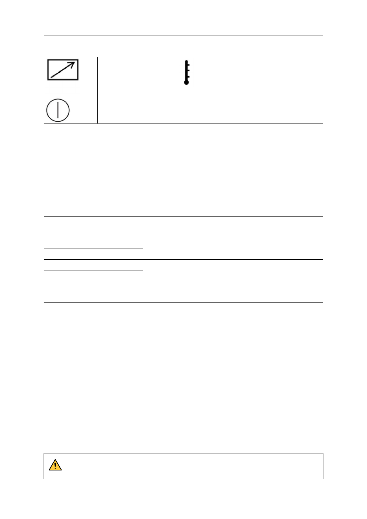
5.2 Symbols
Remote control unit (2) Overheating (3)
Power supply ON (4)
5.3 Connection of welding and return cable
The power source has two outputs, a positive terminal (+) and a negative terminal (-), for
connecting welding and return cables.
Connect the return cable to the negative terminal on the power source. Secure the return
cable's contact clamp to the work piece and ensure that there is good contact between the
work piece and the output for the return cable on the power source.
Recommended maximum current values for connection set cables
I
max
450 A (60% duty cycle)
350 A (100% duty cycle)
550 A (60% duty cycle)
430 A (100% duty cycle)
450 A (60% duty cycle)
350 A (100% duty cycle)
550 A (60% duty cycle)
430 A (100% duty cycle)
Cable area Cable length Note
70 mm
95 mm
70 mm
95 mm
2
2
2
2
6.6 ft - 114.8 ft
(2 - 35 m)
6.6 ft - 114.8 ft
(2 - 35 m)
6.6 ft - 114.8 ft
(2 - 35 m)
6.6 ft - 114.8 ft
(2 - 35 m)
19 pole
19 pole
19 pole, water
19 pole, water
Duty cycle
The duty cycle refers to the time, expressed as a percentage of a ten-minute period, during
which you can weld or cut at a certain load without overloading. The duty cycle is valid for
104°F (40°C).
5.4 Turning the power source on/off
Turn the power source on by turning switch (1) to the ”1” position. Turn the power source off
by turning the switch (1) to the ”0” position. Welding data will be stored regardless of whether
the electrical supply is interrupted abnormally or the power source is switched off in the
normal manner, which allows it to be available the next time the unit is turned on.
5.5 Fan control
The power source has a time circuit, which keeps the fans running for 6.5 minutes after
welding has stopped, then the unit switches to energy-saving mode. The fans start again
when welding begins. The fans run at reduced speed for welding currents up to 150 A, and at
full speed for higher currents.
CAUTION!
The fans may start at any time to protect the power source from overheating.
0463 380 031
- 17 -
© ESAB AB 2015

5 OPERATION
5.6 Overheating protection
The welding power source has overheating protection circuit that operates if the internal
temperature becomes too high. When this occurs, the welding current is blocked and a fault
code is displayed on the control panel. The overheating protection resets automatically when
the temperature has fallen.
5.7 VRD (Voltage Reducing Device)
The VRD function ensures that the open-circuit voltage does not exceed 35 V when welding
is not being carried out. This is indicated by an illuminated VRD LED on the control panel of
the wire feed unit. The VRD function must be activated with ESAT by an qualified service
technician.
The VRD function is blocked when the system senses that welding has started.
5.8 Remote control unit
For more information about the operation of the remote control unit, see the instruction
manual for the control panel.
5.9 MIG/MAG and self-shielded cored wire welding
An arc melts a continuously supplied wire. The weld pool is protected by shielding gas. For
MIG/MAG and self-shielded cored wire welding, the power source is supplemented with:
• wire feed unit
• welding torch
• connection cable between the power source and wire feed unit
• shielding gas bottle
0463 380 031
- 18 -
© ESAB AB 2015

6 MAINTENANCE
6 MAINTENANCE
NOTE!
Regular maintenance is important for safe, reliable operation.
Only persons with the appropriate electrical knowledge (authorized personnel) may remove
the safety plates to connect or carry out service, maintenance or repair work on the welding
equipment.
For information about the cooling unit see the instruction manual for the cooling unit.
CAUTION!
All warranty undertakings from the supplier cease to apply if the customer
attempts any work to rectify any faults in the product during the warranty period.
6.1 Inspection and cleaning
Check regularly that the power source is free from dirt.
The power source should be regularly blown clean using dry compressed air at reduced
pressure. More frequently in dirty environments.
Otherwise the air inlet/outlet may become blocked and cause overheating. To avoid this, the
air filter should be cleaned regularly.
Replacing and cleaning the dust filter:
1. Release the dust filter according to the figure.
2. Blow the filter clean with compressed air (reduced pressure).
3. Ensure that the filter with the finest mesh is placed toward the grill.
4. Reinstall the filter.
6.2 Welding torch
Wear parts should be cleaned and replaced at regular intervals in order to avoid problems
while welding.
0463 380 031
- 19 -
© ESAB AB 2015

7 FAULT TRACING
7 FAULT TRACING
Try these recommended checks and inspections before requesting a visit from an authorized
service technician.
Type of fault Actions
No arc. • Check that the electrical power supply
switch is turned on.
• Check that the electrical, welding current,
and return cables are connected correctly.
• Check that the correct current value is
set.
• Check the electrical power supply fuses.
Welding current is interrupted during welding • Check whether the thermal overload trip
has operated (indicated by the orange
lamp on the front)
• Check the main power supply fuses.
• Check that the return cable is correctly
fastened.
The thermal overload trips frequently • Check to see whether the air filters are
clogged.
• Make sure that you are not exceeding the
rated data for the power source (i.e. that
the unit is not being overloaded).
Poor welding performance. • Check that the welding current and return
cables are connected correctly.
• Check that the correct current value is
set.
• Check that the correct welding wires are
being used.
• Check the electrical power supply fuses.
Nothing happens when the trigger on the
welding torch is pushed.
• Check the fuse on the rear part of the
power source.
• Check if the welding and return cables
are damaged.
• Check that the wire feeder works
correctly. See the wire feeder instruction
manual.
0463 380 031
- 20 -
© ESAB AB 2015

8 ORDERING SPARE PARTS
8 ORDERING SPARE PARTS
CAUTION!
Repair and electrical work should be performed by an authorised ESAB service
technician. Use only ESAB original spare and wear parts.
The Mig 4004i Pulse 460 V is designed and tested in accordance with the international
standards IEC 60974-1 and US standards ANSI/IEC 60974-1:2008. It is the obligation
of the service unit that carried out the service or repair work to make sure that the
product still conforms to said standard.
Spare parts may be ordered through your nearest ESAB dealer, see the back cover of this
document. When ordering, please state product type, serial number, designation and spare
part number in accordance with the spare parts list. This facilitates dispatch and ensures
correct delivery.
0463 380 031
- 21 -
© ESAB AB 2015

DIAGRAM
DIAGRAM
0463 380 031
- 22 -
© ESAB AB 2015

ORDERING NUMBERS
ORDERING NUMBERS
Ordering
Denomination Type Note
number
0465 152 882 Welding power source Aristo® Mig 4004i Pulse 460V version
0463 396 001 Spare parts list Aristo® Mig 4004i Pulse
Technical documentation is available on the Internet at: www.esab.com
0463 380 031
- 23 -
© ESAB AB 2015

SPARE PARTS LIST
SPARE PARTS LIST
Item Ordering no. Denomination
1 0462 197 001 Dust filter
2 0463 396 001 Warning label
0463 380 031
- 24 -
© ESAB AB 2015

ACCESSORIES
ACCESSORIES
Trolleys
0462 151 880
0459 839 039
Trolley 11, 4-wheels
Spare parts list for trolley
0463 125 880 Trolley bracket for Trolley 11
Option when no cooling unit is assembled
0460 564 880
0460 815 880
Trolley 8, 2-wheels
Shelf for YardFeed and MobileFeed
0460 565 880 Trolley 9, 4-wheel
For counterbalance device.
Trolley accessories
0461 310 880 Bracket kit
To assembly 4004i/5004i to the 2/4-wheel
trolley 0460 564/565
0460 946 880 Stabilizer 4-wheel for counterbalance
0463 380 031
- 25 -
© ESAB AB 2015

ACCESSORIES
0458 705 880 Counterbalance device
Includes mast and counterbalance
Wire feeders
0460 526 486
0460 526 896
0460 526 481
0460 526 891
0459 906 896
Feed 3004 U6
Feed 3004 U6, water-cooled
Feed 3004 for U8
2
Feed 3004 for U82, water-cooled
YardFeed 2000 U6, water-cooled
Feeder accessories
0458 674 880 1 Bobbin cover, plastic
0459 431 880 1 Bobbin cover, metal
0463 380 031
- 26 -
© ESAB AB 2015

ACCESSORIES
0455 410 001 1 Adapter for 5 kg bobbin
0459 233 880 1 Adapter for 440 mm bobbin
0458 706 880 1 Lifting eye
F102 440 880
899F50
2 Quick connector Marathon Pac™
2 Quick connector Marathon Pac™ NA
0558 002 354 Connector Adapter Marathon Pac™ NA
0463 380 031
- 27 -
© ESAB AB 2015

ACCESSORIES
0458 707 880 1 Wheel kit for feeder, front wheels
turnable
0457 341 881 1 Strain relief for welding torch
0459 234 880 Strain relief for interconnection cables
Cooler
0462 300 880 Water cooling unit, COOL1
0456 855 881 Flow guard, COOL1
0463 380 031
- 28 -
© ESAB AB 2015

ACCESSORIES
Control panels
0460 820 880 Aristo®U82, complete including holder
0460 820 881 Aristo®U82, plus complete including
holder
0460 877 891 Control cable extension U82, 7.5 m
Connection set, 70 mm
0349 312 450
0349 312 451
0349 312 452
0349 312 453
0349 312 454
0349 312 455
5.6 ft (1.7 m)
16.0 ft (5 m)
32.8 ft (10 m)
49.2 ft (15 m)
82.0 ft (25 m)
114.8 ft (35 m)
Connection set water, 70 mm
0459 528 790
0459 528 791
0459 528 792
5.6 ft (1.7 m)
16.0 ft (5 m)
32.8 ft (10 m)
2
2
0459 528 793
0459 528 794
0459 528 795
0463 380 031
49.2 ft (15 m)
82.0 ft (25 m)
114.8 ft (35 m)
- 29 -
© ESAB AB 2015

ACCESSORIES
Remote controls
0459 491 880 Remote control unit MTA1 CAN
MIG/MAG: wire feed speed and voltage
MMA: current and arc force
TIG: current, pulse and background current
0459 491 882 Remote control M1 10 Prog. CAN
Remote control cable 10 pole - 4 pole
0459 960 880
0459 960 881
0459 960 882
0459 960 883
16 ft (5m)
32.8 ft (10 m)
82.0 ft (25 m)
10 in. (0.25 m)
Remote adapter kit
0459 681 880
0459 681 881
For Miggy-/Railtrac
For MXH PP and PSF RS3
Connection kit
0459 020 883 For MXH™ 300/400w PP connection kit
Information on PSF welding torches can be found in separate brochures.
0463 380 031
- 30 -
© ESAB AB 2015

ACCESSORIES
0463 380 031
- 31 -
© ESAB AB 2015

ESAB Welding & Cutting Products, Florence, SC Welding Equipment
COMMUNICATION GUIDE - CUSTOMER SERVICES
A CUSTOMER SERVICE QUESTIONS:
Telephone: (800) 362-7080 / Fax: (800) 634-7548 Hours: 8.00 AM to 7:00 PM EST
Order Entry Product Availability Pricing Order Information Returns
B ENGINEERING SERVICE:
Telephone: (834) 664-4416 / Fax: (800) 446-5693 Hours: 7.30 AM to 5:00 PM EST
Warranty Returns Authorized Repair Stations Welding Equipment Troubleshooting
C TECHNICAL SERVICE:
Telephone: (800) ESAB-123 / Fax: (843) 664-4452 Hours: 8.00 AM to 5:00 PM EST
Part Numbers Technical Applications Specifications Equipment Recommendations
D LITERATURE REQUESTS:
Telephone: (843) 664-5562 / Fax: (843) 664-5548 Hours: 7.30 AM to 4:00 PM EST
E WELDING EQUIPMENT REPAIRS:
Telephone: (843) 664-4487 / Fax: (843) 664-5557 Hours: 7.30 AM to 3:30 PM EST
Repair Estimates Repair Status
F WELDING EQUIPMENT TRAINING:
Telephone: (843) 664-4428 / Fax: (843) 679-5864 Hours: 7.30 AM to 4:00 PM EST
Training School Information and Registrations
G WELDING PROCESS ASSISTANCE:
Telephone: (800) ESAB-123 / Fax: Hours: 7.30 AM to 4:00 PM EST
H TECHNICAL ASST. CONSUMABLES:
Telephone: (800) 933-7070 / Fax: Hours: 7.30 AM to 5:00 PM EST
IF YOU DO NOT KNOW WHOM TO CALL
Telephone: (800) ESAB-123
Fax: (843) 664-4452
Hours: 7:30 AM to 5:00 PM EST
or
visit us on the web at http://www.esabna.com
The ESAB web site offers:
Comprehensive Product Information
Material Safety Data Sheets
Warranty Registration
Instruction Literature Download Library
Distributor Locator
Global Company Information
Press Releases
Customer Feedback & Support
ESAB Welding & Cutting Products
PO BOX 100545, Florence SC 29501-0545
© ESAB AB 2015
 Loading...