

Applied Interface
Robot S4- A360
AH 0736
Instruction manual
Installation manual
0460 278 074 20110524
Valid for serial no.
541-636-6813,541-636-6814,541-636-6816 and 0541-838-6819

ENGLISH 4. . . . . . . . . . . . . . . . . . . . . . . . . . . . . . . . . . . . . . . . . . . . . .
Rights reserved to alter specifications without notice.
- 2 -

- 3 -

ENGLISH
1 SAFETY 5. . . . . . . . . . . . . . . . . . . . . . . . . . . . . . . . . . . . . . . . . . . . . . . . . . . . . . . . . . .
2 INTRODUCTION 7. . . . . . . . . . . . . . . . . . . . . . . . . . . . . . . . . . . . . . . . . . . . . . . . . . .
2.1 Equipment 7. . . . . . . . . . . . . . . . . . . . . . . . . . . . . . . . . . . . . . . . . . . . . . . . . . . . . . . . . . . . . . . .
3 TECHNICAL DATA 7. . . . . . . . . . . . . . . . . . . . . . . . . . . . . . . . . . . . . . . . . . . . . . . . .
4 INSTALLATION 7. . . . . . . . . . . . . . . . . . . . . . . . . . . . . . . . . . . . . . . . . . . . . . . . . . . .
4.1 Location 8. . . . . . . . . . . . . . . . . . . . . . . . . . . . . . . . . . . . . . . . . . . . . . . . . . . . . . . . . . . . . . . . . .
4.2 Connection instructions 8. . . . . . . . . . . . . . . . . . . . . . . . . . . . . . . . . . . . . . . . . . . . . . . . . . . . .
5 OPERATION 9. . . . . . . . . . . . . . . . . . . . . . . . . . . . . . . . . . . . . . . . . . . . . . . . . . . . . . .
5.1 Connections and control devices 9. . . . . . . . . . . . . . . . . . . . . . . . . . . . . . . . . . . . . . . . . . . .
5.2 Function description 9. . . . . . . . . . . . . . . . . . . . . . . . . . . . . . . . . . . . . . . . . . . . . . . . . . . . . . .
6 MAINTENANCE 10. . . . . . . . . . . . . . . . . . . . . . . . . . . . . . . . . . . . . . . . . . . . . . . . . . . .
6.1 Inspection and cleaning 10. . . . . . . . . . . . . . . . . . . . . . . . . . . . . . . . . . . . . . . . . . . . . . . . . . . .
6.2 Fault-tracing 10. . . . . . . . . . . . . . . . . . . . . . . . . . . . . . . . . . . . . . . . . . . . . . . . . . . . . . . . . . . . . .
7 ORDERING SPARE PARTS 11. . . . . . . . . . . . . . . . . . . . . . . . . . . . . . . . . . . . . . . . .
8 FUNCTION DESCRIPTION OF I/O SIGNALS 13. . . . . . . . . . . . . . . . . . . . . . . . . .
8.1 Configuration of the I/O-version (Aristot U8 I/O) 13. . . . . . . . . . . . . . . . . . . . . . . . . . . . . . . .
8.2 Input data I/O signal from control equipment (robot) to the welding equipment 13. . . . .
8.3 Output I/O signal from welding equipment to control equipment 15. . . . . . . . . . . . . . . . . .
8.4 Others 15. . . . . . . . . . . . . . . . . . . . . . . . . . . . . . . . . . . . . . . . . . . . . . . . . . . . . . . . . . . . . . . . . . .
DIAGRAM 16. . . . . . . . . . . . . . . . . . . . . . . . . . . . . . . . . . . . . . . . . . . . . . . . . . . . . . . . . . . .
ORDERING NUMBER 17. . . . . . . . . . . . . . . . . . . . . . . . . . . . . . . . . . . . . . . . . . . . . . . . .
SPARE PARTS LIST 18. . . . . . . . . . . . . . . . . . . . . . . . . . . . . . . . . . . . . . . . . . . . . . . . . .
TOCe
- 4 -
GB
1 SAFETY
Users of ESAB equipment have the ultimate responsibility for ensuring that anyone who works on or
near the equipment observes all the relevant safety precautions. Safety precautions must meet the
requirements that apply to this type of equipment. The following recommendations should be ob
served in addition to the standard regulations that apply to the workplace.
All work must be carried out by trained personnel well-acquainted with the operation of the equip
ment. Incorrect operation of the equipment may lead to hazardous situations which can result in in
jury to the operator and damage to the equipment.
1. Anyone who uses the equipment must be familiar with:
S its operation
S location of emergency stops
S its function
S relevant safety precautions
S welding and cutting
2. The operator must ensure that:
S no unauthorized person is stationed within the working area of the equipment when it is
started up.
S no-one is unprotected when the arc is struck
3. The workplace must:
S be suitable for the purpose
S be free from drafts
4. Personal safety equipment
S Always wear recommended personal safety equipment, such as safety glasses, flame-proof
clothing, safety gloves.
S Do not wear loose-fitting items, such as scarves, bracelets, rings, etc., which could become
trapped or cause burns.
5. General precautions
S Make sure the return cable is connected securely.
S Work on high voltage equipment may only be carried out by a qualified electrician.
S Appropriate fire extinquishing equipment must be clearly marked and close at hand.
S Lubrication and maintenance must not be carried out on the equipment during operation.
CAUTION
Read and understand the instruction manual before
installing or operating.
CAUTION
This product is solely intended for arc welding.
br06d1ea
- 5 -
© ESAB AB 2007
GB
WARNING
Arc welding and cutting can be injurious to yourself and others. Take precausions when welding and
cutting. Ask for your employer's safety practices which should be based on manufacturers' hazard
data.
ELECTRIC SHOCK - Can kill
S Install and earth the unit in accordance with applicable standards.
S Do not touch live electrical parts or electrodes with bare skin, wet gloves or wet clothing.
S Insulate yourself from earth and the workpiece.
S Ensure your working stance is safe.
FUMES AND GASES - Can be dangerous to health
S Keep your head out of the fumes.
S Use ventilation, extraction at the arc, or both, to take fumes and gases away from your breathing zone
and the general area.
ARC RAYS - Can injure eyes and burn skin.
S Protect your eyes and body. Use the correct welding screen and filter lens and wear protective
clothing.
S Protect bystanders with suitable screens or curtains.
FIRE HAZARD
S Sparks (spatter) can cause fire. Make sure therefore that there are no inflammable materials nearby.
NOISE - Excessive noise can damage hearing
S Protect your ears. Use earmuffs or other hearing protection.
S Warn bystanders of the risk.
MALFUNCTION - Call for expert assistance in the event of malfunction.
Read and understand the instruction manual before installing or operating.
PROTECT YOURSELF AND OTHERS!
ESAB can provide you with all necessary welding protection and accessories.
Dispose of electronic equipment at the recycling facility!
In observance of European Directive 2002/96/EC on Waste Electrical and Electronic
Equipment and its implementation in accordance with national law, electrical and/or
electronic equipment that has reached the end of its life must be disposed of at a
recycling facility.
As the person responsible for the equipment, it is your responsibility to obtain
information on approved collection stations.
For further information contact the nearest ESAB dealer.
br06d1ea
- 6 -
© ESAB AB 2007
GB
2 INTRODUCTION
Applied Interface Robot S4 A360 checks and converts the CAN bus signals from
the power source to the welding robot and is used for CAN bus controlled power
sources, such as AristoMig 400/500 with Aristot U8 I/O.
Applied Interface Robot S4 A360 converts analog and digital signals to field bus
communication (CAN) and from field bus signals to digital and analog signals.
2.1 Equipment
Applied Interface Robot S4 A360 is supplied with an instruction manual.
3 TECHNICAL DATA
Applied Interface Robot S4 A360
Mains voltage 42 V 50 - 60 Hz
Mains voltage 2 (from robot) 24 V DC
Fuse 1 A
External power source robot +/- 15V to robot
Robot connection 48 pin connection socket
Weight 6.1 kg
Dimensions (l x w x h) 365 x 351 x 110 mm
Protection class IP23
Enclosure class
The IP code indicates the enclosure class, i. e. the degree of protection against penetration by solid
objects or water. Equipment marked IP23 is designed for indoor and outdoor use.
4 INSTALLATION
The installation must be executed by a professional.
CAUTION
This product is intended for industrial use. In a domestic environment this product may
cause radio interference. It is the user's responsibility to take adequate precautions.
WARNING
When welding in an environment with increased electrical danger, only power
sources intended for this environment may be used. These power sources are
marked with the symbol
br06d1ea
- 7 -
© ESAB AB 2007

GB
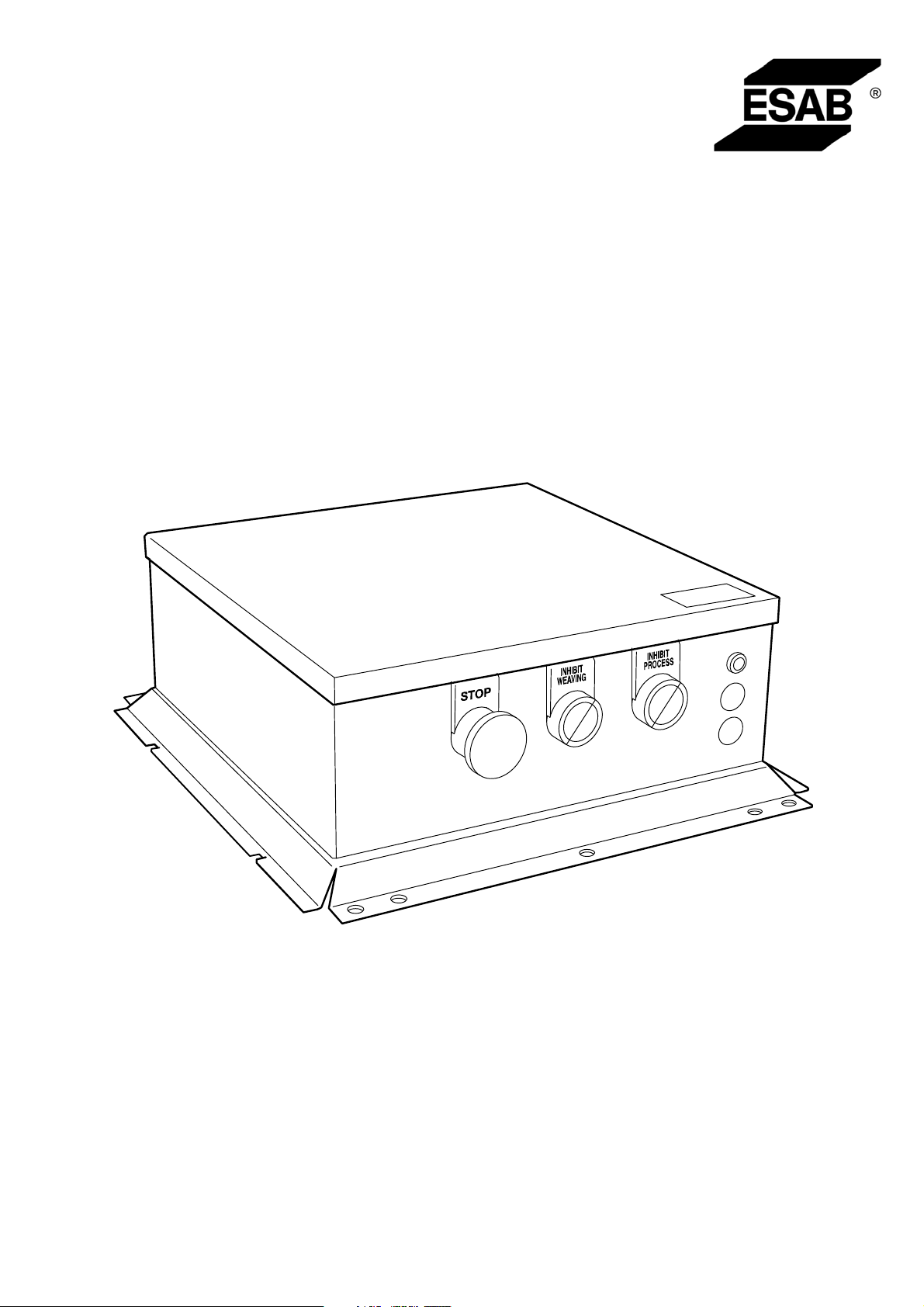
4.1 Location
Applied Interface Robot S4 A360 is installed above the power source. Remove the
rubber mat (C) on the power source and then slide the flange of the interface box (A)
into the side profiles (B) of the power source, see the illustration below.
IMPORTANT! Screw the 3 screws into place on the front of the interface box,
sufficiently hard in the screw threads that electrical connection is made. Check that
electrical connection has been established.
4.2 Connection instructions
AH 0738
Complete descriptions of the power source / wire feed unit are available in separate instruction
manuals.
br06d1ea
- 8 -
© ESAB AB 2007

GB
5 OPERATION
General safety regulations for the handling of the equipment can be found on
page 5. Read through before you start using the equipment!
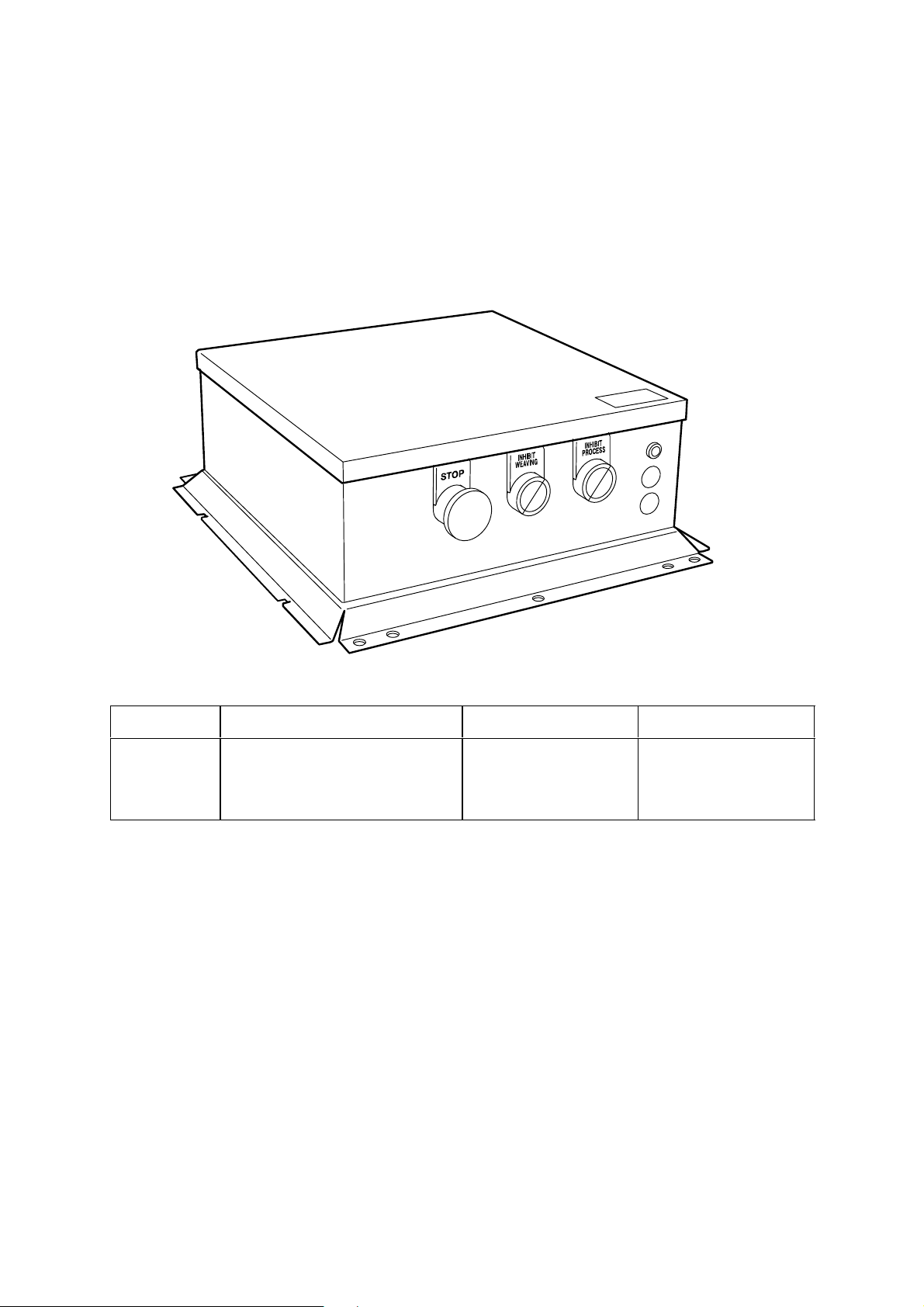
5.1 Connections and control devices
1 Stop, pushbutton YELLOW 6 Fuse / 1A 24 VDC from robot
2 Inhibit weaving, YELLOW push button 7 Connecting extra equipment (lubricating/
cleaning) socket 8 pin.
3 Inhibit process, YELLOW pushbutton 8 Connection for operating cable from power
source (12-pin CAN bus)
4 Indicator lamp (WHITE), power supply
from robot.
5 Connection for signals to/from the robot's
welding gun (48-pin socket connector)
5.2 Function description
9 Connection (negative) for arc voltage
detection (1 pin socket plug)
Applied Interface Robot S4 A360 is connected to the robot cabinet and the power
source.
When the Interface box is connected to AristoMig 400 or AristoMig 500 with
AristoPendant U8 with part number 0456 290 991 or higher.
The type plate is located on the
rear side of the Interface box.
br06d1ea
- 9 -
© ESAB AB 2007

GB
AH 0736
Button A - Stop
The button stops the robot and the welding process.
Button B – Runs the robot program without weaving
The INHIBIT WEAVING button prevents weaving in the robot program when pressed
(lights yellow). The robot program can be run with and without weaving.
Button C – Runs the robot program without the welding process
The INHIBIT PROCESS button blocks the welding process when pressed (lights
yellow). One can run the robot program and test the movement pattern without
welding.
6 MAINTENANCE
Regular maintenance is important for safe, reliable operation.
CAUTION
All guarantee undertakings from the supplier cease to apply if the customer himself
attempts any work in the product during the guarantee period in order to rectify any faults.
6.1 Inspection and cleaning
Regularly check that the interface box has electrical connection with the power
source and that the connections are correctly connected and not faulty.
6.2 Fault-tracing
S Has the indicator lamp (white) on the front gone out?
Check that the fuse is intact.
S Ensure that the wiring is correctly located in its connectors.
Complete descriptions of the power source, wire feed unit and control panel are available in separate
instruction manuals.
br06d1ea
- 10 -
© ESAB AB 2007

GB
7 ORDERING SPARE PARTS
Applied Interface Robot S4- A360 is designed and tested in accordance with the inter
national and European standards 60974-1 and 60974-10 . It is the obligation of the
service unit which has carried out the service or repair work to make sure that the pro
duct still conforms to the said standard.
Spare parts may be ordered through your nearest ESAB dealer, see the last page of
this publication.
* * *
NOTE! 8. FUNCTION DESCRIPTION OF I/O SIGNALS is only in English and is
primarily meant for the integrator and installation of the Interface box on page 13.
br06d1ea
- 11 -
© ESAB AB 2007

NOTES
.............................................................................................................................................................
.............................................................................................................................................................
.............................................................................................................................................................
.............................................................................................................................................................
.............................................................................................................................................................
.............................................................................................................................................................
.............................................................................................................................................................
.............................................................................................................................................................
.............................................................................................................................................................
.............................................................................................................................................................
.............................................................................................................................................................
.............................................................................................................................................................
.............................................................................................................................................................
.............................................................................................................................................................
.............................................................................................................................................................
.............................................................................................................................................................
.............................................................................................................................................................
.............................................................................................................................................................
.............................................................................................................................................................
.............................................................................................................................................................
.............................................................................................................................................................
.............................................................................................................................................................
.............................................................................................................................................................
.............................................................................................................................................................
.............................................................................................................................................................
.............................................................................................................................................................
.............................................................................................................................................................
.............................................................................................................................................................
.............................................................................................................................................................
.............................................................................................................................................................
.............................................................................................................................................................
notes
- 12 -

8 FUNCTION DESCRIPTION OF I/O SIGNALS
The Aristot Retrofit I/O is the interface between the welding robot and the welding
equipment. The Aristot Retrofit I/O converts the robot's I/O signals to field bus
signals to the welding equipment. The Aristot Retrofit I/O also converts the field bus
signals from the welding equipment to I/O signals to the welding robot.
8.1 Configuration of the I/O-version (Aristot U8 I/O)
With the service function 38 in the Aristot U8 I/O unit you can activate or deactivate
the different blocks of I/O's.
For more information, please read the Service manual for AristoPendant U8.
8.2 Input data I/O signal from control equipment (robot) to the
welding equipment
Welding start
The signal starts the welding process but before the welding process starts the quick
stop and stop signals are checked to ensure that they are not active.
Stop
The signal shuts off the robot and the welding process.
Quick stop
The signal stops the equipment if it is active in the welding process, it carries out a
normal stop without crater filling. The function is used when a quick stop is required
but it gives a normal burnback time to prevent the wire sticking in the weld pool. The
signal also blocks the start command.
Wire inching
Used when one wants to feed wire without welding voltage.
The signal starts the wire feed without the welding voltage being activated. The wire
feed unit feeds wire at the set speed. If the signal is active during the welding
process, the command is ignored.
If both welding and wire inching are activated at the same time the equipment will
ignore the wire inching command and start the welding process.
Gas flushing
Gas flushing is used when measuring the gas flow or to flush any air or moisture
from the gas hoses before welding starts. Gas flushing is carried out without voltage
or wire feed occurring.
Welding start always activates the gas valve even if the manual gas command is
given. In the same way the gas valve for gas post flow is always closed if it is not
closed already.
Gas flushing operates parallel to the functions gas pre-flow and gas post-flow. To
control the welding gas from the robot, set the gas pre-flow to minimum and the gas
post-flow to maximum, and then control the welding gas using the gas flushing
functions.
br04d2e
- 13 -
© ESAB AB 2007

Spatter cleaning
The signal controls the valve for air cleaning welding spatter.
Touch Sense Response
This command is used by the robot to sense where the wire is.
When the function is active, the power source will give out current limited idle voltage
to see if the wire is in contact with the workpiece. On contact, the output signal
”Touch Sense Response” is activated.
Active analog
The signal is used to switch between the analog and digital remote modes.
Analogue active allows analog control of the welding parameters, voltage, arc
voltage and the wire feed speed.
NOTE! On AristotRetrofit I/O the function is always activated.
If the welding method Aristot SuperPulse is to be used, the ”analog active” signal
must be deactivated.
When the analogue method is activated the power source will not use the preset
values for wire feed speed and voltage when new welding data is selected. When
”analog active” is activated the robot controls arc voltage and wire feed speed using
analog signals.
With the analog active signal deactivated, welding data is exchanged with preset
welding data such as voltage, wire feed speed to fixed set welding parameters.
The pre-programmed welding data (schedules) is requested from the
Aristot U8 I/O welding data memory.
Welding data
With the signals memory 1, 2, 4, 8, one accesses saved welding data (schedules) in
Aristot U8 I/O.
The binary coded combinations of these signals can be used to recall the memories
1-15 in the Aristot U8 I/O memory bank.
A complete set of welding data includes all settings that can be made in
Aristot U8 I/O, see the instruction manual for AristoPendant U8.
Voltage reference
This signal is used by the robot for analog control of the welding voltage if analog
active is selected. It stretches from 0-10V and corresponds to welding voltage socket
as follows.
0V reference gives a deviation on the selected arc voltage of -10V
10V reference gives a deviation on the selected arc voltage of +10V
If the machine is in non-synergy mode, the equipment will use the appreciated value.
0V reference gives arc voltage 8V
10V reference gives arc voltage 60V
br04d2e
- 14 -
© ESAB AB 2007

Wire feed speed reference signal
The signal is used by the robot to make analog adjustments to the wire feed speed.
The internal solution is 0.1 m/min.
Input voltage
0 V Mini. value for wire feed (normally 0.8 m/min) (RoboFeed)
10 V Max. value for wire feed (normally 25 m /min)
8.3 Output I/O signal from welding equipment to control
equipment
Arc Acknowledge
The signal is activated after established welding start if the voltage and current
strength lie within weldable limits. The signal disappears if welding cannot be
established.
The criterion for establishing a welding arc is that the process control has passed the
start- procedure, which means that there it not sufficient with only a short circuit to
meet the criteria. Normal delay from the first contact, which is acknowledged by the
welding arc (wire feed time for this that the first contact is established ) is in the
interval 2 to 20 ms. If there is a poor start to the welding arc the ”Arc acknowledge” is
further delayed.
Touch Sense Response
This signal indicates contact in the welding circuit, i.e. that the wire is in contact with
the workpiece. To obtain ”touch sense response” the ”touch sense” input signal must
be activated.
Collision robot (AntiCollisionDetect)
The signal comes via the internal CAN bus from the feeding mechanism
(RoboFeed). The signal indicates that the robot's breaker has activated. The
interface activates a relay which breaks two safety loops from the robot, at which the
robot orders a quick stop of both robot and the welding equipment.
The output is high when the welding gun breaker is tripped (the signal is sent to the
robot).
Machine faults
The signal is low when an error has been detected in the welding equipment.
8.4 Others
0-cable 4 mm
2
S The 0-cable 4mm2 between the power source and the robot cabin is delivered in length of 15
m and is to be cut to the length required at installation.
Start up time
S The start up time of the Interface box when current/power is activated can be delayed up to
1 minute.
- 15 -
br04d2e
© ESAB AB 2007
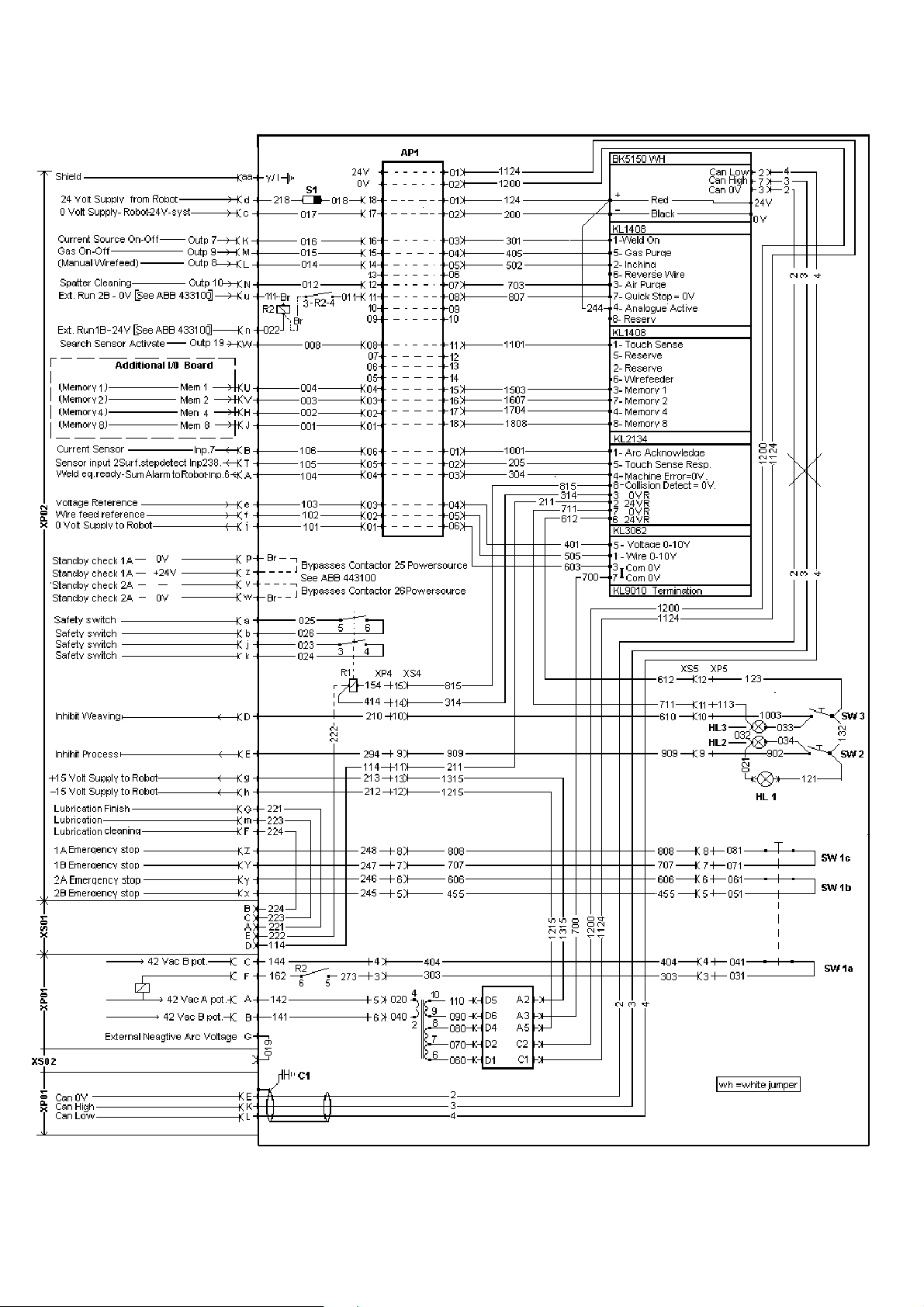
Diagram
br06dia
- 16 Edition 20110524
Applied Interface Robot S4- A360
Ordering number
AH 0736
Ordering no. Denomination Type Notes
- Applied Interface Robot
S4 A360
br06order
- 17 Edition 20110524
Applied Interface Robot S4- A360
Spare parts list
Item Qty Ordering no. Denomination Notes
101 1 0461 095 001 Cover
102 1 0461 110 881 Gable back 48p 1x12p
103 2 0452 116 004 Relay 2VX 24VDC
104 2 0452 116 008 Socket
105 1 0368 544 002 Sleeve socket 8-pol.
106 1 0368 543 008 Panel plug 48-pol
107 1 0458 681 891 Cable D-sub compl.
108 1 0467 911 884 Capacitor
109 1 0456 686 880 Clamp
110 1 0368 543 003 Burndy plug M/C Mount 12 way
- 50 0323 945 004 Contact pins (W) Min. 50 pcs
111 1 0443 740 007 Sign bracket
112 1 0457 800 001 Insulation
113 1 0366 285 001 Protection cap 12-pol
114 1 0193701 001 Fuse holder knob
115 1 0567 900 132 Fuse 1A
116 1 0193 701 002 Fuse holder
117 1 0461 092 001 Chassi S3 A350
118 1 0461 098 001 Adapter plate S3 A350
119 1 0461 092 880 Gable front. S3 A350
122 1 0461 740 011 Stop buttom Baco
121 3 0443 740 007 Sign bracket
120 1 0443 740 010 Sign “STOP”
123 2 0443 740 002 Contact block 14A/230 VAC (Stop buttom)
124 2 0443 740 003 Push buttom switch
125 1 0443 740 008 Sign “Inhibit Process”
126 1 0443 740 009 Sign “Inhibit Weawing”
127 1 0443 740 005 Lamp 24 VDC Baco
128 2 0443 740 004 Bracket
129 2 0443 740 006 Contact block 14A/230 VAC
20 0194 179 327 Screw MRT Ground-cutter M5x12
2 0194 120 285 Screw MRT M4x6
4 - Screw RTS ST 3.5 x 9.5
2 - Nut M6M 4 M4x6
2 - Washer (VEC) D7.6/4.1
1 0458 950 001 Sign MEL30/MEL48
1 0192 576 003 Lamp 24V White
br04asp1
- 18 -
Edition 20110524

Applied Interface Robot S4- A360
br04asp1
- 19 -
Edition 20110524

Applied Interface Robot S4- A360
Item Qty Ordering no. Denomination Notes
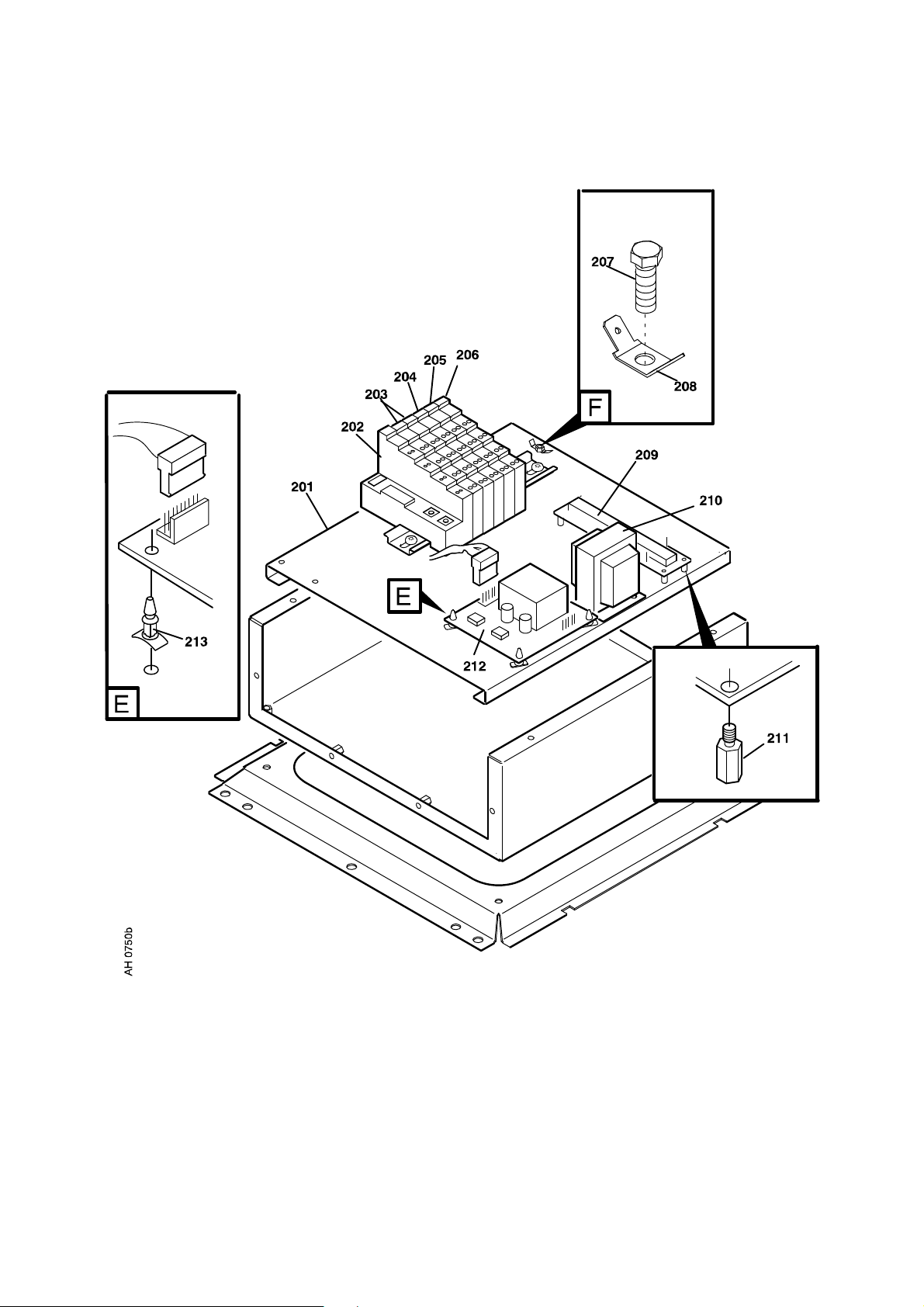
MOUNTING PLATE
201 1 0461 097 001 Mounting plate
202 1 0194 204 001 Terminal Bud coupler BK5151
203 2 0194 205 001 Terminal Digital input KL1408
204 1 0194 205 002 Terminal Digitial output KL2134
205 1 0194 205 003 Terminal Analog input KL3062
206 1 0194 205 004 Terminal Bus End KL9010
207 1 0194 179 327 Screw, MRT Ground-cutter M5x12
208 1 0191 548 009 Flat pin 6.3 x 0.8 M6
209 1 0487 427 880 Printed Circuit Board
210 1 0319 828 003 Transformer WFU
211 1 0192 790 102 Circuit Card holder 6.3 mm
212 1 0740 545 001 Printed Circuit Board 24 V
212 1 0740 545 002 Printed Circuit Board 15 V
213 2 0192 547 002 Quick-Act lock nut B6
br04asp2
- 20 -
Edition 20110524
Applied Interface Robot S4- A360
br04asp2
- 21 -
Edition 20110524

NOTES
.............................................................................................................................................................
.............................................................................................................................................................
.............................................................................................................................................................
.............................................................................................................................................................
.............................................................................................................................................................
.............................................................................................................................................................
.............................................................................................................................................................
.............................................................................................................................................................
.............................................................................................................................................................
.............................................................................................................................................................
.............................................................................................................................................................
.............................................................................................................................................................
.............................................................................................................................................................
.............................................................................................................................................................
.............................................................................................................................................................
.............................................................................................................................................................
.............................................................................................................................................................
.............................................................................................................................................................
.............................................................................................................................................................
.............................................................................................................................................................
.............................................................................................................................................................
.............................................................................................................................................................
.............................................................................................................................................................
.............................................................................................................................................................
.............................................................................................................................................................
.............................................................................................................................................................
.............................................................................................................................................................
.............................................................................................................................................................
.............................................................................................................................................................
.............................................................................................................................................................
.............................................................................................................................................................
notes
- 22 -

NOTES
.............................................................................................................................................................
.............................................................................................................................................................
.............................................................................................................................................................
.............................................................................................................................................................
.............................................................................................................................................................
.............................................................................................................................................................
.............................................................................................................................................................
.............................................................................................................................................................
.............................................................................................................................................................
.............................................................................................................................................................
.............................................................................................................................................................
.............................................................................................................................................................
.............................................................................................................................................................
.............................................................................................................................................................
.............................................................................................................................................................
.............................................................................................................................................................
.............................................................................................................................................................
.............................................................................................................................................................
.............................................................................................................................................................
.............................................................................................................................................................
.............................................................................................................................................................
.............................................................................................................................................................
.............................................................................................................................................................
.............................................................................................................................................................
.............................................................................................................................................................
.............................................................................................................................................................
.............................................................................................................................................................
.............................................................................................................................................................
.............................................................................................................................................................
.............................................................................................................................................................
.............................................................................................................................................................
notes
- 23 -

ESAB subsidiaries and representative offices
Europe
AUSTRIA
ESAB Ges.m.b.H
Vienna-Liesing
Tel: +43 1 888 25 11
Fax: +43 1 888 25 11 85
BELGIUM
S.A. ESAB N.V.
Brussels
Tel: +32 2 745 11 00
Fax: +32 2 745 11 28
BULGARIA
ESAB Kft Representative Office
Sofia
Tel/Fax: +359 2 974 42 88
THE CZECH REPUBLIC
ESAB VAMBERK s.r.o.
Vamberk
Tel: +420 2 819 40 885
Fax: +420 2 819 40 120
DENMARK
Aktieselskabet ESAB
Herlev
Tel: +45 36 30 01 11
Fax: +45 36 30 40 03
FINLAND
ESAB Oy
Helsinki
Tel: +358 9 547 761
Fax: +358 9 547 77 71
FRANCE
ESAB France S.A.
Cergy Pontoise
Tel: +33 1 30 75 55 00
Fax: +33 1 30 75 55 24
GERMANY
ESAB GmbH
Solingen
Tel: +49 212 298 0
Fax: +49 212 298 218
GREAT BRITAIN
ESAB Group (UK) Ltd
Waltham Cross
Tel: +44 1992 76 85 15
Fax: +44 1992 71 58 03
ESAB Automation Ltd
Andover
Tel: +44 1264 33 22 33
Fax: +44 1264 33 20 74
HUNGARY
ESAB Kft
Budapest
Tel: +36 1 20 44 182
Fax: +36 1 20 44 186
ITALY
ESAB Saldatura S.p.A.
Bareggio (Mi)
Tel: +39 02 97 96 8.1
Fax: +39 02 97 96 87 01
NORWAY
AS ESAB
Larvik
Tel: +47 33 12 10 00
Fax: +47 33 11 52 03
POLAND
ESAB Sp.zo.o.
Katowice
Tel: +48 32 351 11 00
Fax: +48 32 351 11 20
PORTUGAL
ESAB Lda
Lisbon
Tel: +351 8 310 960
Fax: +351 1 859 1277
ROMANIA
ESAB Romania Trading SRL
Bucharest
Tel: +40 316 900 600
Fax: +40 316 900 601
RUSSIA
LLC ESAB
Moscow
Tel: +7 (495) 663 20 08
Fax: +7 (495) 663 20 09
SLOVAKIA
ESAB Slovakia s.r.o.
Bratislava
Tel: +421 7 44 88 24 26
Fax: +421 7 44 88 87 41
SPAIN
ESAB Ibérica S.A.
Alcalá de Henares (MADRID)
Tel: +34 91 878 3600
Fax: +34 91 802 3461
SWEDEN
ESAB Sverige AB
Gothenburg
Tel: +46 31 50 95 00
Fax: +46 31 50 92 22
ESAB international AB
Gothenburg
Tel: +46 31 50 90 00
Fax: +46 31 50 93 60
SWITZERLAND
ESAB AG
Dietikon
Tel: +41 1 741 25 25
Fax: +41 1 740 30 55
UKRAINE
ESAB Ukraine LLC
Kiev
Tel: +38 (044) 501 23 24
Fax: +38 (044) 575 21 88
North and South America
ARGENTINA
CONARCO
Buenos Aires
Tel: +54 11 4 753 4039
Fax: +54 11 4 753 6313
BRAZIL
ESAB S.A.
Contagem-MG
Tel: +55 31 2191 4333
Fax: +55 31 2191 4440
CANADA
ESAB Group Canada Inc.
Missisauga, Ontario
Tel: +1 905 670 02 20
Fax: +1 905 670 48 79
MEXICO
ESAB Mexico S.A.
Monterrey
Tel: +52 8 350 5959
Fax: +52 8 350 7554
USA
ESAB Welding & Cutting Products
Florence, SC
Tel: +1 843 669 44 11
Fax: +1 843 664 57 48
Asia/Pacific
CHINA
Shanghai ESAB A/P
Shanghai
Tel: +86 21 2326 3000
Fax: +86 21 6566 6622
INDIA
ESAB India Ltd
Calcutta
Tel: +91 33 478 45 17
Fax: +91 33 468 18 80
INDONESIA
P.T. ESABindo Pratama
Jakarta
Tel: +62 21 460 0188
Fax: +62 21 461 2929
JAPAN
ESAB Japan
Tokyo
Tel: +81 45 670 7073
Fax: +81 45 670 7001
MALAYSIA
ESAB (Malaysia) Snd Bhd
USJ
Tel: +603 8023 7835
Fax: +603 8023 0225
SINGAPORE
ESAB Asia/Pacific Pte Ltd
Singapore
Tel: +65 6861 43 22
Fax: +65 6861 31 95
SOUTH KOREA
ESAB SeAH Corporation
Kyungnam
Tel: +82 55 269 8170
Fax: +82 55 289 8864
UNITED ARAB EMIRATES
ESAB Middle East FZE
Dubai
Tel: +971 4 887 21 11
Fax: +971 4 887 22 63
Africa
EGYPT
ESAB Egypt
Dokki-Cairo
Tel: +20 2 390 96 69
Fax: +20 2 393 32 13
SOUTH AFRICA
ESAB Africa Welding & Cutting Ltd
Durbanvill 7570 - Cape Town
Tel: +27 (0)21 975 8924
Distributors
For addresses and phone
numbers to our distributors in
other countries, please visit our
home page
www.esab.com
THE NETHERLANDS
ESAB Nederland B.V.
Amersfoort
Tel: +31 33 422 35 55
Fax: +31 33 422 35 44
www.esab.com
110426© ESAB AB
 Loading...