

Page 1
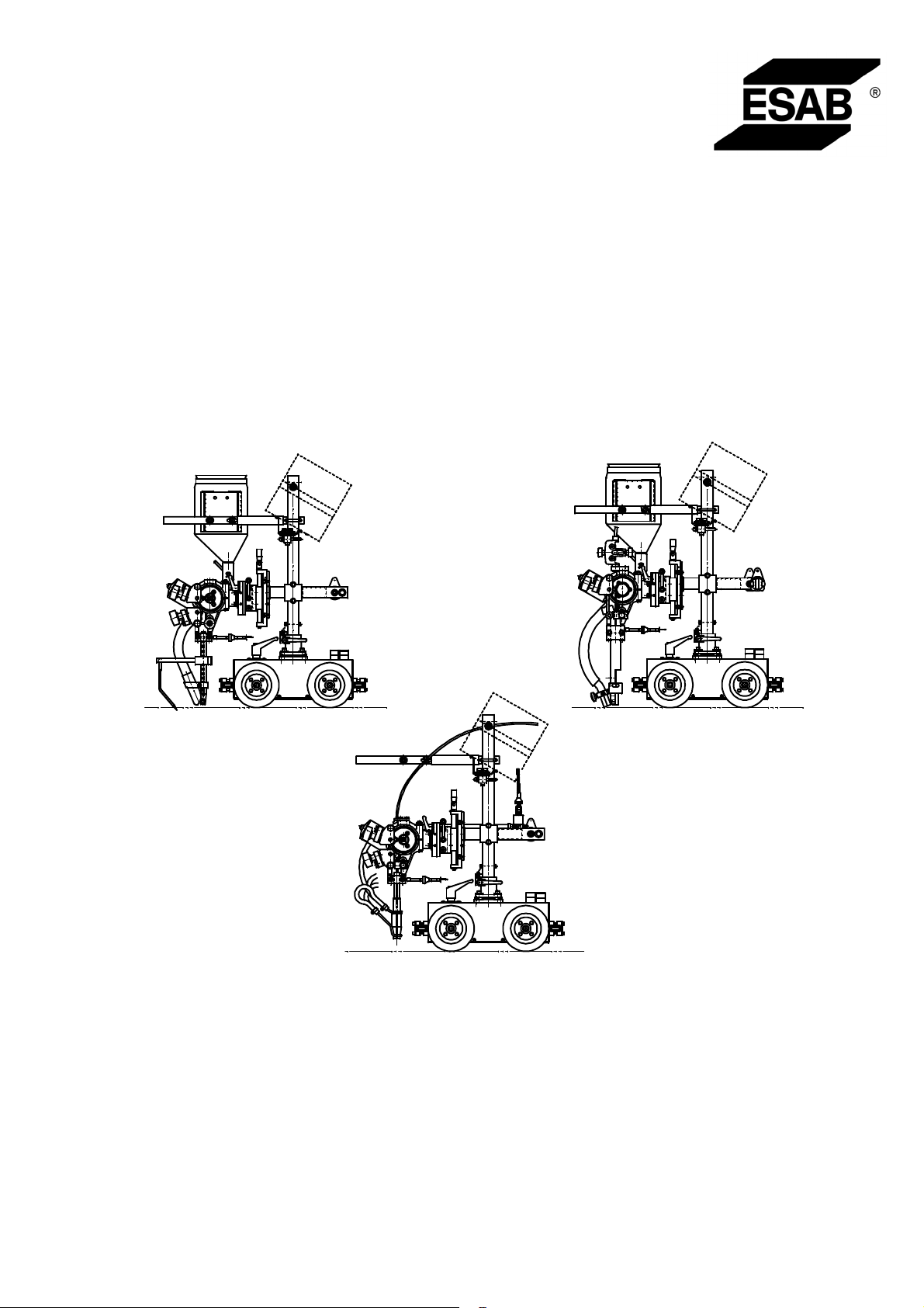
A2 Automatic Welding
Machines with Welding
Control Unit PEI
A2 TF/ A2 TF (Twin)/ A2 TG
101103105102021104022100020040060
Bruksanvisning
Brugsanvisning
Bruksanvisning
Käyttöohjeet
Instruction manual
Betriebsanweisung
Valid for serial no. 2400449 365 060 2003--03--27
Page 2

SVENSKA 4..............................................
DANSK 22................................................
NORSK 40................................................
SUOMI 58................................................
ENGLISH 76..............................................
DEUTSCH 94.............................................
Rätt till ändring av specifikationer utan avisering förbehålles.
Ret til ændring af specifikationer uden varsel forbeholdes.
Rett til å endre spesifikasjoner uten varsel forbeholdes.
Oikeudet muutoksiin pidätetään.
Rights reserved to alter specifications without notice.
Änderungen vorbehalten.
-- 2 --
Page 3

FÖRSÄKRAN OM ÖVERENSST ÄMMELSE
Esab Welding Equipment AB, 695 81 Laxå, Sverige, försäkrar under eget ansvar att
svetsutrustning A2 TF / A2 TG från serienummer 136 är i överensstämmelse med
standard EN 60292 och EN 60204 enligt villkoren i direktiv (89/392/EEG) med tillägg
(93/68/EEG).
-- -- -- -- -- -- -- -- -- -- -- -- -- -- -- -- -- -- -- -- -- -- -- -- -- -- -- -- -- -- -- -- -- -- -- -- -- -- -- -- -- -- -- -- -- -- -- -- -- -- -- -- -- -- -- -- -- -- -- -- -- -- -- --------
OVERENSSTEMMELSEERKLÆRING
Esab Welding Equipment AB, S-- 695 81 Laxå, Sverige, erklærer på eget ansvar, at
svejseudstyr A2 TF / A2 TG fra serienummer 136 er i overensstemmelse med standarden EN 60292 og EN 60204 ifølge betingelserne i direktiv (89/392/EØF) med til læg (93/68/EØF).
-- -- -- -- -- -- -- -- -- -- -- -- -- -- -- -- -- -- -- -- -- -- -- -- -- -- -- -- -- -- -- -- -- -- -- -- -- -- -- -- -- -- -- -- -- -- -- -- -- -- -- -- -- -- -- -- -- -- -- -- -- -- -- --------
FORSIKRING OM SAMSVAR
Esab Welding Equipment AB, S --695 81 Laxå, Sverige, forsikrer på eget ansvar at
sveiseutstyr A2 TF / A2 TG fra serienummer 136 er i overensstemmelse med standard EN 60292 og EN 60204 i følge vilkårene i dir ektiv (89/392/EF) med tillegg
(93/68/EF).
-- -- -- -- -- -- -- -- -- -- -- -- -- -- -- -- -- -- -- -- -- -- -- -- -- -- -- -- -- -- -- -- -- -- -- -- -- -- -- -- -- -- -- -- -- -- -- -- -- -- -- -- -- -- -- -- -- -- -- -- -- -- -- --------
VAATIMUSTENMUKAISUUSVAKUUTUS
Esab Welding Equipment AB, S--695 81 Laxå, Ruotsi, vakuuttaa omalla vastuullaan,
että hitsauslaitteisto A2 TF/ A2 TG alkaen sarjanumerosta 136 täyttää standardin EN
60292 ja EN 60204 vaatimukset direktiivin (89/392/ETY) ja sen lisäysten
(93/68/ETY).
-- -- -- -- -- -- -- -- -- -- -- -- -- -- -- -- -- -- -- -- -- -- -- -- -- -- -- -- -- -- -- -- -- -- -- -- -- -- -- -- -- -- -- -- -- -- -- -- -- -- -- -- -- -- -- -- -- -- -- -- -- -- -- --------
DECLARATION OF CONFORMITY
Esab Welding Equipment AB, S--695 81 Laxå, Sweden, gives its unreserved
guarantee that welding equipment A2 TF/ A2 TG from serial number 136 complies
with standard EN 60292 and EN 60204, in accordance with the requirements of directive (89/392/EEC) and addendum (93/68/EEC).
-- -- -- -- -- -- -- -- -- -- -- -- -- -- -- -- -- -- -- -- -- -- -- -- -- -- -- -- -- -- -- -- -- -- -- -- -- -- -- -- -- -- -- -- -- -- -- -- -- -- -- -- -- -- -- -- -- -- -- -- -- -- -- --------
ZULASSUNGSNACHWEIS
Esab Welding Equipment AB, S --695 81 Laxå Schweden, bestätigt hiermit in Eigenverantwortung, daß der Schweißausrüstung A2 TF/ A2 TG ab Seriennummer 136
dem Standard EN 60292 und EN 60204 gemäß den Bedingungen der Direktive
(89/392/EEG) mit Zusatz (93/68/EEG).
-- -- -- -- -- -- -- -- -- -- -- -- -- -- -- -- -- -- -- -- -- -- -- -- -- -- -- -- -- -- -- -- -- -- -- -- -- -- -- -- -- -- -- -- -- -- -- -- -- -- -- -- -- -- -- -- -- -- -- -- -- -- -- -------Laxå 2003--03--27
Martin Andersson
Manager Control Systems & Software
Automation Products
ESAB AB, Welding Automation
695 81 LAXÅ
SWEDEN Tel: + 46 584 81000 Fax: + 46 584 411721
3
Page 4

ENGLISH
1SAFETY 77...........................................................
2 INTRODUCTION 79...................................................
2.1 General 79..................................................................
2.2 Welding Method 79...........................................................
2.3 Definitions 79................................................................
2.4 Technical data 80............................................................
2.5 Main components A2 TF (SAW) 81.............................................
2.6 Main Components A2 TG (MIG/MAG) 81........................................
2.7 Description of Main Components 82............................................
3 INSTALLATION 83....................................................
3.1 General 83..................................................................
3.2 Mounting 83.................................................................
3.3 Adjusting the brake hub 83....................................................
3.4 Connections 84..............................................................
4 OPERATION 86.......................................................
4.1 General 86..................................................................
4.2 Loading the welding wire (A2 TF , A2 TG) 87.....................................
4.3 Changing the feed roller (A2 TF, A2 TG) 88......................................
4.4 Contact equipment for Submerged arc welding 89................................
4.5 Contact equipment for MIG/MAG welding 90.....................................
4.6 Refilling with flux powder (Submerged arc welding) 91.............................
4.7 Transportation of the Automatic Welding Machine 91..............................
4.8 Conversion of A2 TF (Submerged--arc) to MIG/MAG welding 91....................
4.9 Conversion of A2 TF (submerged--arc welding) to Twin--arc 91.....................
5 MAINTENANCE 92....................................................
5.1 General 92..................................................................
5.2 Daily 92.....................................................................
5.3 Periodic 92..................................................................
6 TROUBLESHOOTING 93..............................................
6.1 General 93..................................................................
6.2 POSSIBLE FAULTS 93.......................................................
7 ORDERING OF SPARE PARTS 93......................................
DIMENSION DRAWING 112................................................
SPARE PARTS LIST 113...................................................
TOCe
-- 7 6 --
Page 5

GB
1SAFETY
Users of ESAB welding equipment have the ultimate responsibility for ensuring that anyone who
works on or near the equipment observes all the relevant safety precautions. Safety precautions
must meet the requirements that apply to this type of welding equipment. The following recommendations should be observed in addition to the standard regulations that apply to the workplace.
All work must be carried out by trained personnel well--acquainted with the operation of the welding
equipment. Incorrect operation of the equipment may lead to hazardous situations which can result
in injury to the operator and damage to the equipment.
1. Anyone who uses the welding equipment must be familiar with:
S its operation
S location of emergency stops
S its function
S relevant safety precautions
S welding
2. The operator must ensure that:
S no unauthorised person is stationed within the working area of the equipment when it is
started up.
S no--one is unprotected when the arc is struck
3. The workplace must:
S be suitable for the purpose
S be free from draughts
4. Personal safety equipment
S Always wear recommended personal safety equipment, such as safety glasses, flame--proof
clothing, safety gloves.
S Do not wear loose--fitting items, such as scarves, bracelets, rings, etc., which could become
trapped or cause burns.
5. General precautions
S Make sure the return cable is connected securely.
S Work on high voltage equipment may only be carried out by a qualified electrician.
S Appropriate fire extinquishing equipment must be clearly marked and close at hand.
S Lubrication and maintenance must not be carried out on the equipment during operation.
fhb5safe
-- 7 7 --
Page 6
GB
WARNING
ARC WELDING AND CUTTING CAN BE INJURIOUS TO YOURSELF AND OTHERS. TAKE PRECAUTIONS WHEN WELDING. ASK FOR YOUR EMPLOYER’S SAFETY PRACTICES WHICH SHOULD BE
BASED ON MANUFACTURERS’ HAZARD DATA.
ELECTRIC SHOCK -- Can kill
S Install and earth the welding unit in accordance with applicable standards.
S Do not touch live electrical parts or electrodes with bare skin, wet gloves or wet clothing.
S Insulate yourself from earth and the workpiece.
S Ensure your working stance is safe.
FUMES AND GASES -- Can be dangerous to health
S Keep your head out of the fumes.
S Use ventilation, extraction at the arc, or both, to take fumes and gases away from your breathing zone
and the general area.
ARC RAYS -- Can injure eyes and burn skin.
S Protect your eyes and body. Use the correct welding screen and filter lens and wear protective
clothing.
S Protect bystanders with suitable screens or curtains.
FIRE HAZARD
S Sparks (spatter) can cause fire. Make sure therefore that there are no inflammable materials nearby.
NOISE -- Excessive noise can damage hearing
S Protect your ears. Use earmuffs or other hearing protection.
S Warn bystanders of the risk.
MALFUNCTION -- Call for expert assistance in the event of malfunction.
READ AND UNDERSTAND THE INSTRUCTION MANUAL BEFORE INSTALLING OR OPERATING.
PROTECT YOURSELF AND OTHERS!
fhb5safe
-- 7 8 --
Page 7

GB
2 INTRODUCTION
2.1 General
The A2 TF automatic welding machine is designed for Submerged Arc Welding of
butt and fillet joints.
The A2 TG automatic welding machine is designed for MIG/MAG welding of butt and
fillet joints.
All other applications are prohibited.
They are intended for use in combination with A2 Welding Control Unit (PEI) and
ESAB’s welding power source LAF.
2.2 Welding Method
2.2.1 Submerged Arc Welding (SAW)
For submerged arc welding the A2 TF automatic welding machine is always to be
used.
S Submerged arc Light Duty.
Submerged arc light duty with a Ø 20 mm connector permits a load up to 800 A
(100%).
This version can be equipped with feed rollers for single or twin wire welding
(twin--arc). A special knurled feed roller is available for flux--cored wire, which
guarantees even wire feed without the risk of deformation due to high feed pressure.
2.2.2 MIG/MAG Welding
For MIG/MAG welding use either automatic welding machine A2 TG.
In MIG/MAG welding the welding bead is shielded by way of shielding gas.
The welding head is water--cooled. T he cooling water is supplied by hoses from
connections intended for the purpose.
2.3 Definitions
SAW welding The weld bead is protected by a cover of flux during the
welding.
SAW Light duty Permits welding with lower current load and thin wire.
MIG/MAG welding The weld bead is protected by shielding gas during
welding.
Twin--arc welding Welding with two wires in one welding head.
fhb5d1ea
-- 7 9 --
Page 8
g
GB
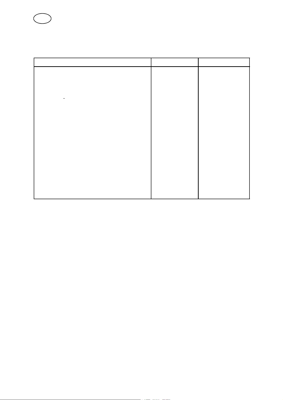
2.4 Technical data
2.4.1 A2 TF and A2 TG
A2 TF (UP) A2 TG (MIG/MAG)
Supply voltage 42 V AC 42 V AC
Permissible load at 100 %: 800 A DC 600 A DC
Wire dimensions:
solid single wire
hollow wire
twin wire
Wire feed speed, max 9m/min 16 m/min
Brake hub braking torque 1.5 Nm 1.5 Nm
Travel speed 0.1--2.0 m/min 0.1--2.0 m/min
Turning radius for circumferential welding, min 1500 mm 1500 mm
Pipe diameter for internal joint welding, min 1100 mm 1 100 mm
Max. weight of wire 30 kg 30 kg
Flux container volume
(Not to be filled with preheated flux)
Weight (excl. wire and flux) 46 kg 46 kg
Max. lateral inclination (whole unit)
1.6--4.0 mm 0.8--2.5 mm
1.6--4.0 mm
2x1.2--2.0 mm
6l -- --
25_ 25_
1.2--3.2 mm
-- --
fhb5d1ea
-- 8 0 --
Page 9
GB
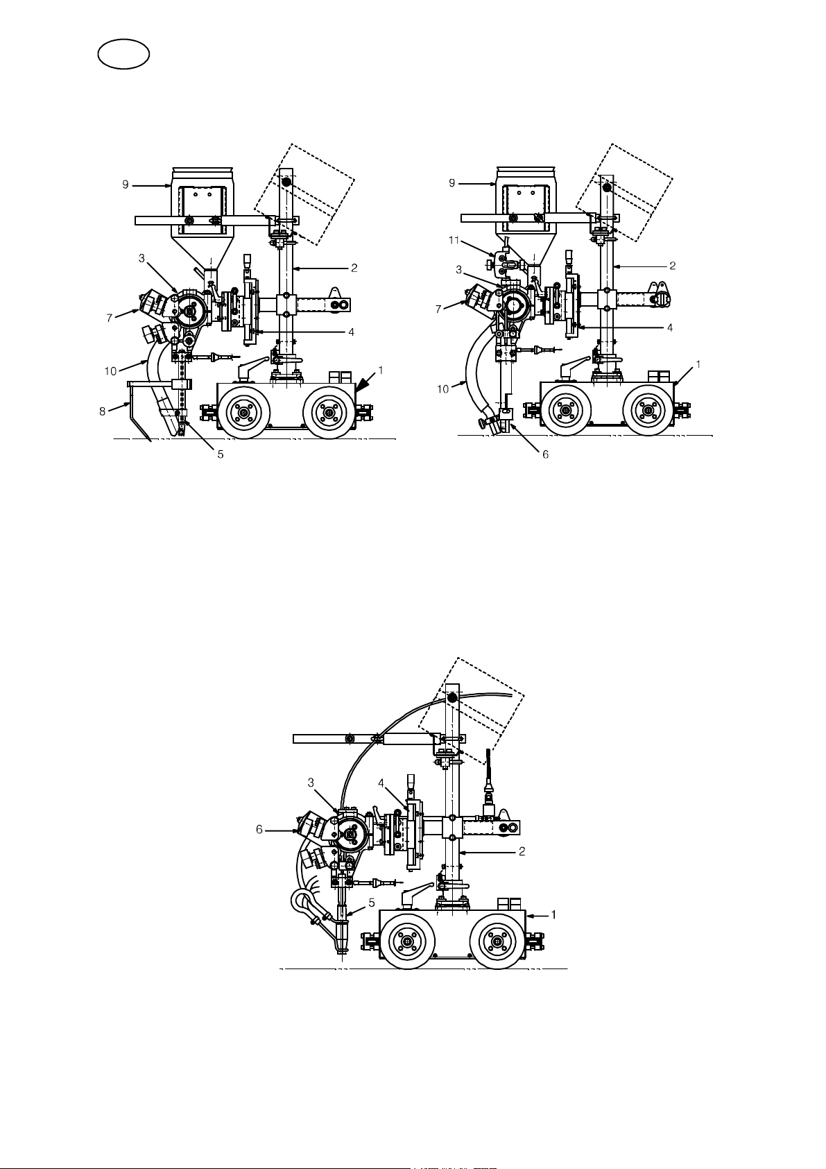
2.5 Main components A2 TF (SAW)
1. Carriage
2. Carrier
3. Wire feed unit
4. Slide kit, manual
5. Contact tube
6. Connector (Twin)
7. Wire feed motor
8. Guide pin
2.6 Main Components A2 TG (MIG/MAG)
9. Flux hopper
10. Flux tube
1 1. Fine--wire straightener
1. Carriage
2. Carrier
3. Wire feed unit
4. Slide kit, manual
See on page 82 for a description of the main components.
fhb5d1ea
-- 8 1 --
5. Connector
6. Wire feed motor
Page 10
GB
2.7 Description of Main Components
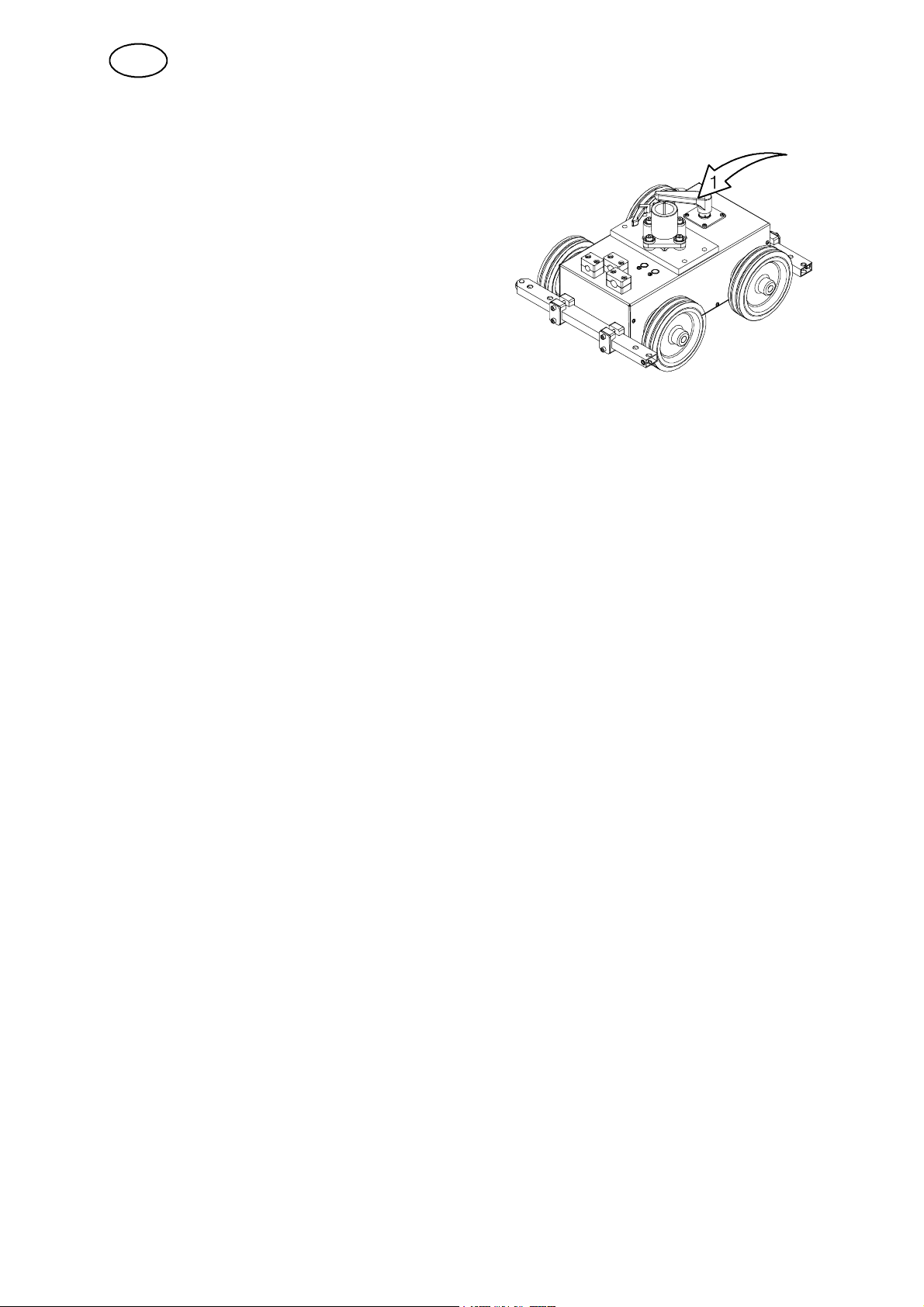
2.7.1 Carriage
The carriage is provided with 4--wheel drive.
The carriage can be secured by way of the
locking lever (1).
2.7.2 Carrier
The control box, wire feed unit and flux hopper,
among other things, are to be fitted on the carrier.
2.7.3 Wire Feed Unit / Wire F eed Unit with four--wheel Drive
The unit is used for guiding and feeding the welding wire down into the contact
tube/connector.
2.7.4 Manual Slides
The horizontal and vertical position of the welding head is adjusted by way of linear
slides. The angular motion can be freely adjusted using the rotary slide.
2.7.5 Contact Tube / Connector
Transfers welding current to the wire during welding.
2.7.6 Wire Feed Moto r
The wire feed motor is used for feeding the welding wire.
2.7.7 Guide Pin
The guide pin is used to help positioning the welding head in the joint.
2.7.8 Flux Hopper / Flux Tube
The flux is filled into the flux hopper and is then transferred to the workpiece through
the flux tube.
The amount of flux to be dropped down is controlled by way of the flux valve fitted to
the flux hopper.
See “Refilling with flux on page 91.
2.7.9 Fine--wire straightener
The unit is used for the straightening of fine wire.
fhb5d1ea
-- 8 2 --
Page 11
GB
3 INSTALLATION
3.1 General
The installation must be executed by a professional.
WARNING
Rotating parts can cause injury, take great care.
3.2 Mounting
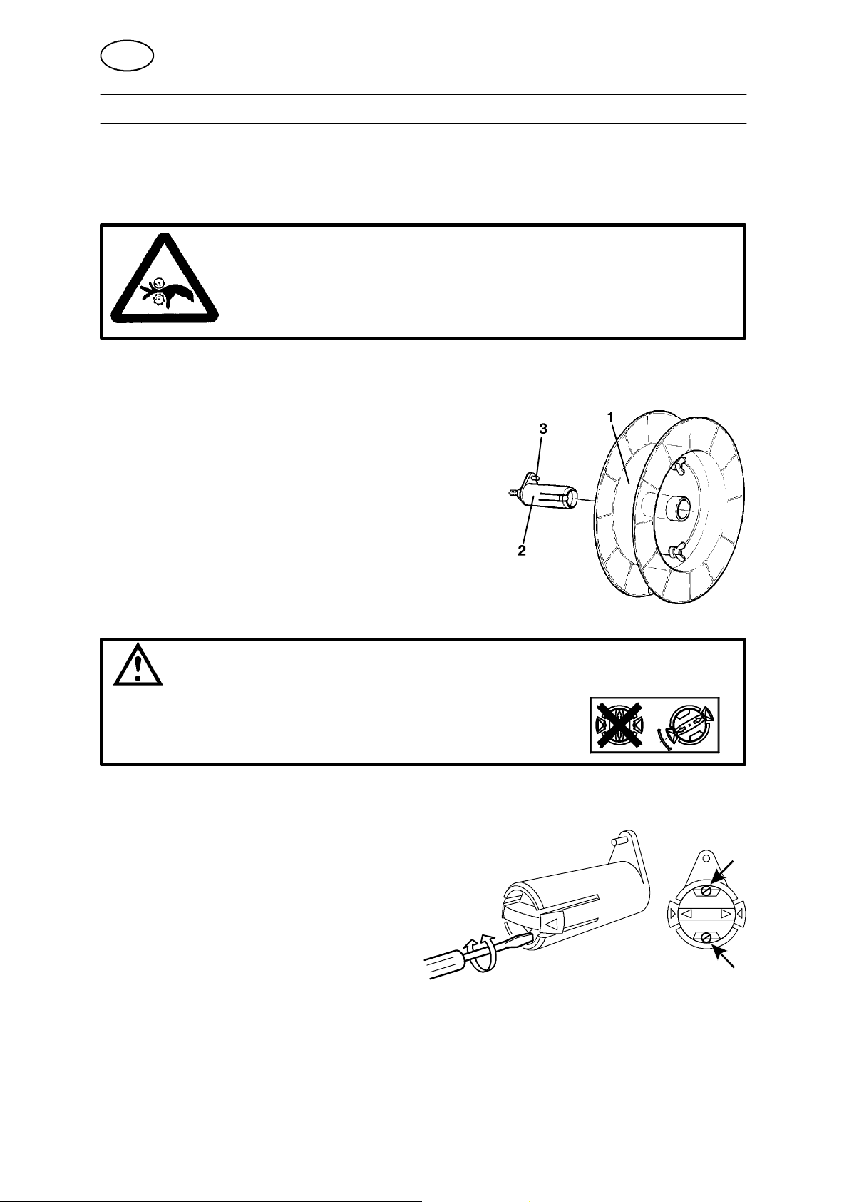
3.2.1 Wire drum (Accessories)
Wire drum (1) is mounted on the brake hub (2).
S Check that the carrier (3) is pointing upwards.
NOTE! The maximum angle for the wire bobbin is 25°.
At extreme angles, wear will occur on the brake hub
locking mechanism and the wire bobbin will slide off
the brake hub.
WARNING
To prevent the r eel sliding off the hub:
S
Lock the reel in place by turning the red knob as shown
on the warning label attached next to the hub.
3.3 Adjusting the brake hub
The brake hub is adjusted when delivered, if readjustment
is required, follow the instructions below. Adjust the brake
hub so that wire is slightly slack when wire feed stops.
S Adjusting the braking torque:
S Turn the r ed handle to the locked
position.
S Insert a screwdriver into the springs in the hub.
Turn the springs clockwise to reduce the braking torque
Turn the springs anticlockwise to increase the braking torque.
NB: Turn both springs through the same amount.
fhb5i1ea
-- 8 3 --
Page 12
GB
3.4 Connections
3.4.1 General
S The A2 Welding Control Unit (PEI) is to be connected by a qualified person.
S For the connection of welding power source LAF, see separate instruction
manual.
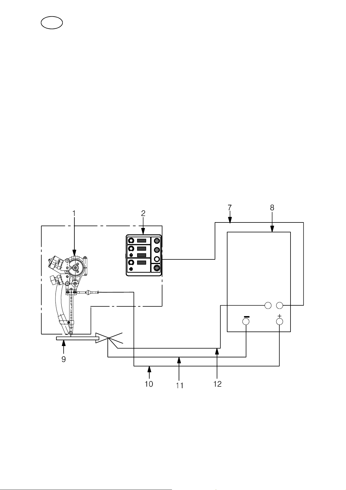
3.4.2 Automatic welding machine A2 TF (Submerged arc welding, SAW)
1. Connect the control cable (7) between the power source (8) and the control box
A2 Welding Control Unit (2).
2. Connect the return cable (11) between the power source (8) and work piece (9).
3. Connect the welding cable (10) between the power source (8) and the automatic
welding machine (1 ).
4. Connect the measurement cable (12) between the power source (8) and
workpiece (9).
fhb5i1ea
-- 8 4 --
Page 13
GB
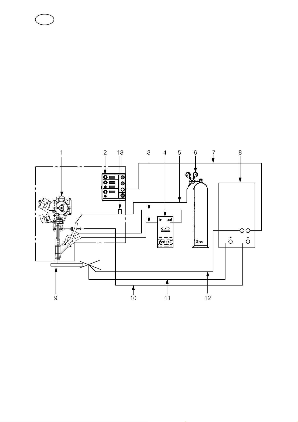
3.4.3 Automatic welding machine A2 T G (Gas metal arc welding, MIG/MAG)
1. Connect the control cable (7) between the power source (8) and control box
A2 Welding Control Unit (2).
2. Connect the return cable (11) between the power source (8) and work piece (9).
3. Connect the welding cable (10) between the power source (8) and the automatic
welding machine (1 ).
4. Connect the gas hose (5) between the r educer valve (6) and the gas connection
(13) on the welding machine.
5. Connect the cooling water hoses ( 3 ) between the cooling unit (4) and the
automatic welding machine (1).
6. Connect the measurement cable (12) between the power source (8) and
workpiece (9).
fhb5i1ea
-- 8 5 --
Page 14
GB
4 OPERATION
4.1 General
Caution:
Have you read and understood the safety information ?
You must not operate the machine beforehand !
General safety regulations for the handling of the equipment can be found on
page 77. Read through before you start using the equipment!
S Select electrode type and flux powder or shielding gas so that the weld material
is as close as possible to the analysis of the base metal.
S Select electrode size and welding data in accordance with the values
recommended by the welding materials supplier.
S Thorough preparation of the weld surfaces is necessary to achieve a good weld.
NOTE! The width of the weld joint gap must be uniform.
S To minimise the risk of heat crack formation, the width of the weld must be
greater than the penetration depth.
S Always carry out a test weld with the same joint type and sheet thickness as the
production work piece.
S For control and adjustment of the automatic welding machine and welding power
supply, see the instruction manual for the A2 Welding Control Unit (PEI).
fhb5o1ea
-- 8 6 --
Page 15
GB
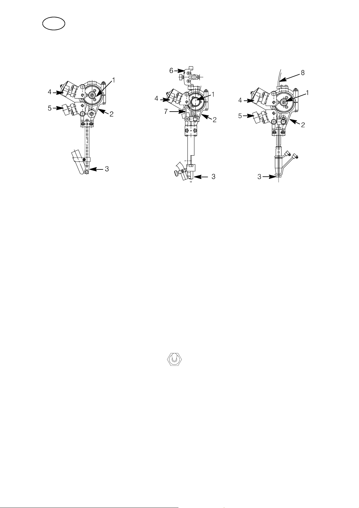
4.2 Loading the welding wire (A2 TF, A2 TG)
A2 TF (UP) A2 TF (UP, Twin) A2 TG (MIG/MAG)
1. Mount the wire drum according to the instructions on page 83.
2. Check that feed roller (1) and contact jaw or contact tip (3) are of the correct
dimension for the selected wire size.
3. For A2 TF (Twin) and A2 TG:
S Feed the wire through the wire guide (8).
4. When welding with fine wire:
S Feed the wire through the fine Wire feed unit (6).
Ensure that the straightener is correctly adjusted so that the wire emerges
straight out through the contact jaws or contact tip (3).
5. Pull the end of the wire through the straightener (2).
S For a wire diameter greater than 2 mm; straighten out 0.5 m of wire and feed
it by hand down through the straightener.
6. Locate the end of the wire in the feed roller (1) groove.
7. Set the wire tension on the feed roller with the knob (4).
S Note! Do not tension more than is required to achieve an even feed.
8. Feed the wire forward 30 mm with on the control box
A2 Welding Control Unit (PEI).
9. Direct the wire by adjusting the knob (5).
S Always use a guide tube (7) to ensure even feed of fine wire (1.6 -- 2.5 mm).
S F or MIG/MAG welding with wire sizes < 1.6 mm, use a guide spiral, which is
inserted in the guide tube (7).
fhb5o1ea
-- 8 7 --
Page 16
GB
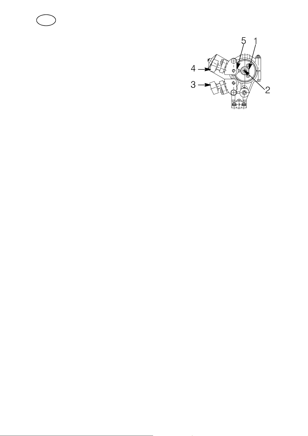
4.3 Changing the feed roller (A2 TF, A2 TG)
Single wire
S Release the knobs (3) and (4).
S Release the hand wheel (2).
S Change the feed roller (1).
They are marked with their respective wire sizes.
Twin wire (Twin--arc)
S Change the feed roller (1) with twin grooves in the same way as for single wire.
S NOTE! The pressure roller (5) must also be changed. A special curved pressure
roller for twin wire replaces the standard pressure roller for single wire.
S Assemble the pressure roller with special stub shaft
(order no. 0146 253 001).
Flux--cored wire for knurled rollers (Accessories)
S Change the feed roller (1) and pressure roller (5) as a pair for the wire size to be
used.
NOTE! A special stub shaft is required for the pressure roller
(order no. 0212 901 101).
S Tighten the pressure screw (4) with moderate pressure to ensure that the
flux--cored wire does not deform.
fhb5o1ea
-- 8 8 --
Page 17
GB
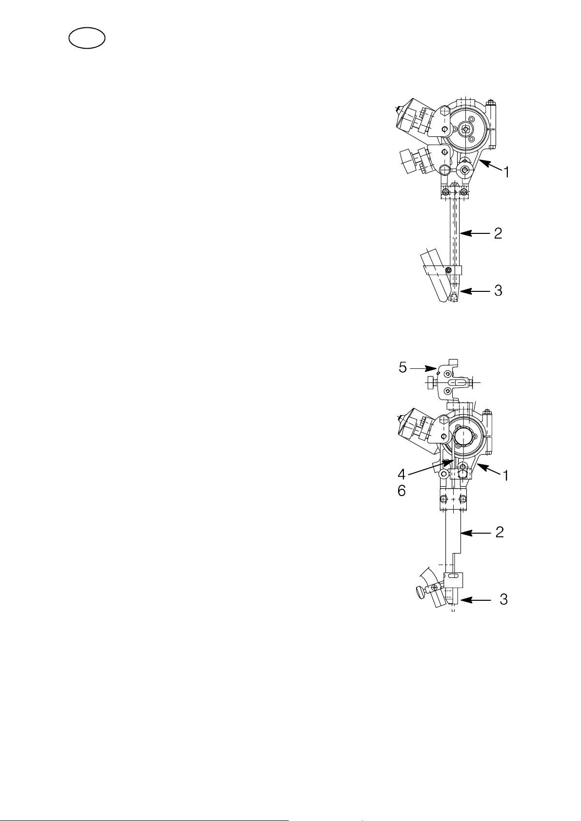
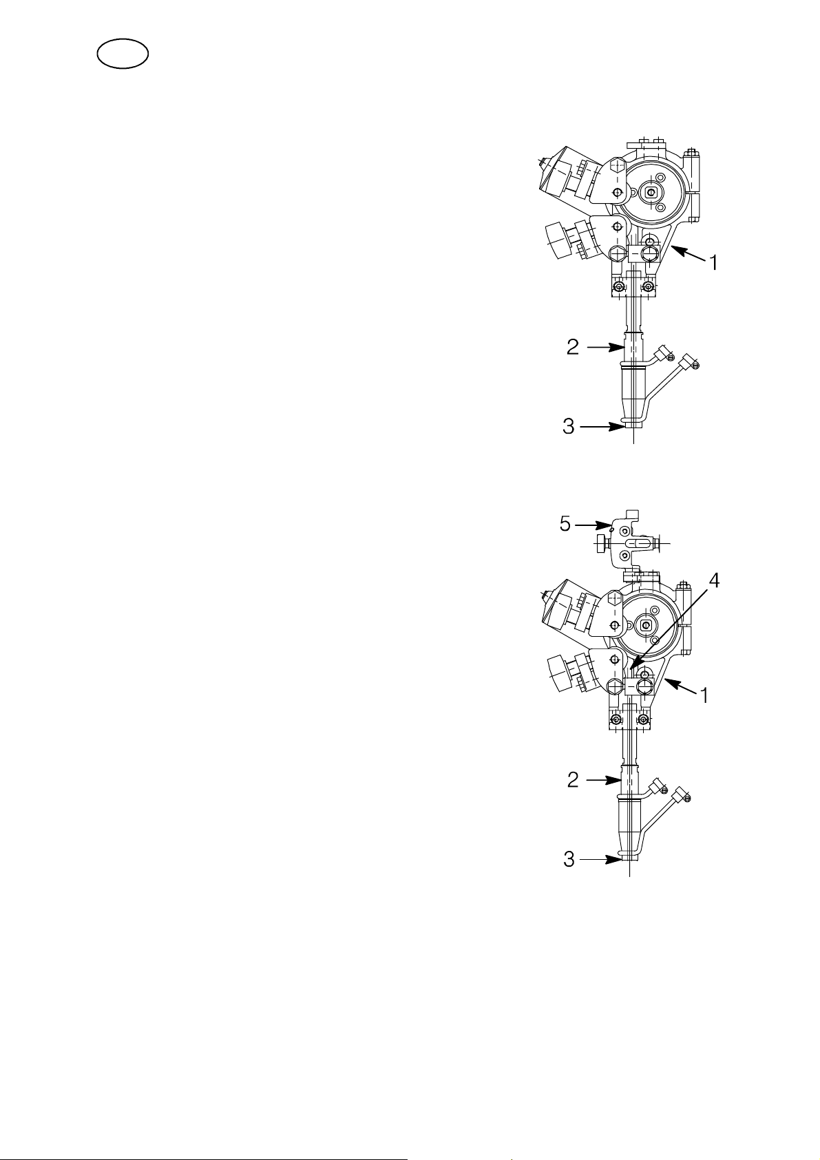
4.4 Contact equipment for Submerged arc welding
4.4.1 For single wire 1.6 -- 4.0 mm. Light duty (D20)
Use automatic welding m achine A2 TF (UP) where
the following are included:
S Wire feed unit (1),
S Connector D20 (2)
S Contact tip (3) (M12 thread).
Tighten the contact tip (3) with a key in order to
ensure that a good contact is achieved.
4.4.2 Fortwinwires2x1.2--2.0mm,LightTwin(D35)
Use automatic welding m achine A2 TF (UP, Twin)
where the following are included:
S Wire feed unit (1),
S Connector Twin D35 (2)
S Contact tip (3) (M6 thread).
S Fine--Wire feed unit (5)
S Guide tubes (4, 6).
Tighten the contact tip (3) with a key in order to
ensure that a good contact is achieved.
Adjustment of the wires for Twin--arc welding :
S Position the wires in the joint so as to achieve optimal weld quality by rotating the
connector. The two wires can be rotated so that they are positioned one after the
other along the line of the joint, or in any position up to 90° across the joint, i.e.
one wire on each side of the joint.
fhb5o1ea
-- 8 9 --
Page 18
GB
4.5 Contact equipment for MIG/MAG welding
4.5.1 For single wire 1.6 -- 2.5 mm (D35)
Use automatic welding machine A2 TG (MIG/MAG)
where the following are included:
S Wire feed unit (1),
S Connector D35 (2)
S Contact tip (3) (M10 thread).
Tighten the contact tip (3) with a key in order to
ensure that a good contact is achieved.
4.5.2 For single wire < 1.6 mm (D35)
Use automatic welding machine A2 TG (MIG/MAG)
where the following are included:
S Wire feed unit (1),
S Connector D35 (2)
S Contact tip (3) (M12 thread).
S Guide tubes (4).
Tighten the contact tip (3) with a key in order to
ensure that a good contact is achieved.
Use the following accessories:
S Fine--wire straightener (5) to be fitted on top of
the clamp of the wire feed unit (1).
S Guide spiral to be inserted into the guide tube (4).
fhb5o1ea
-- 9 0 --
Page 19
GB
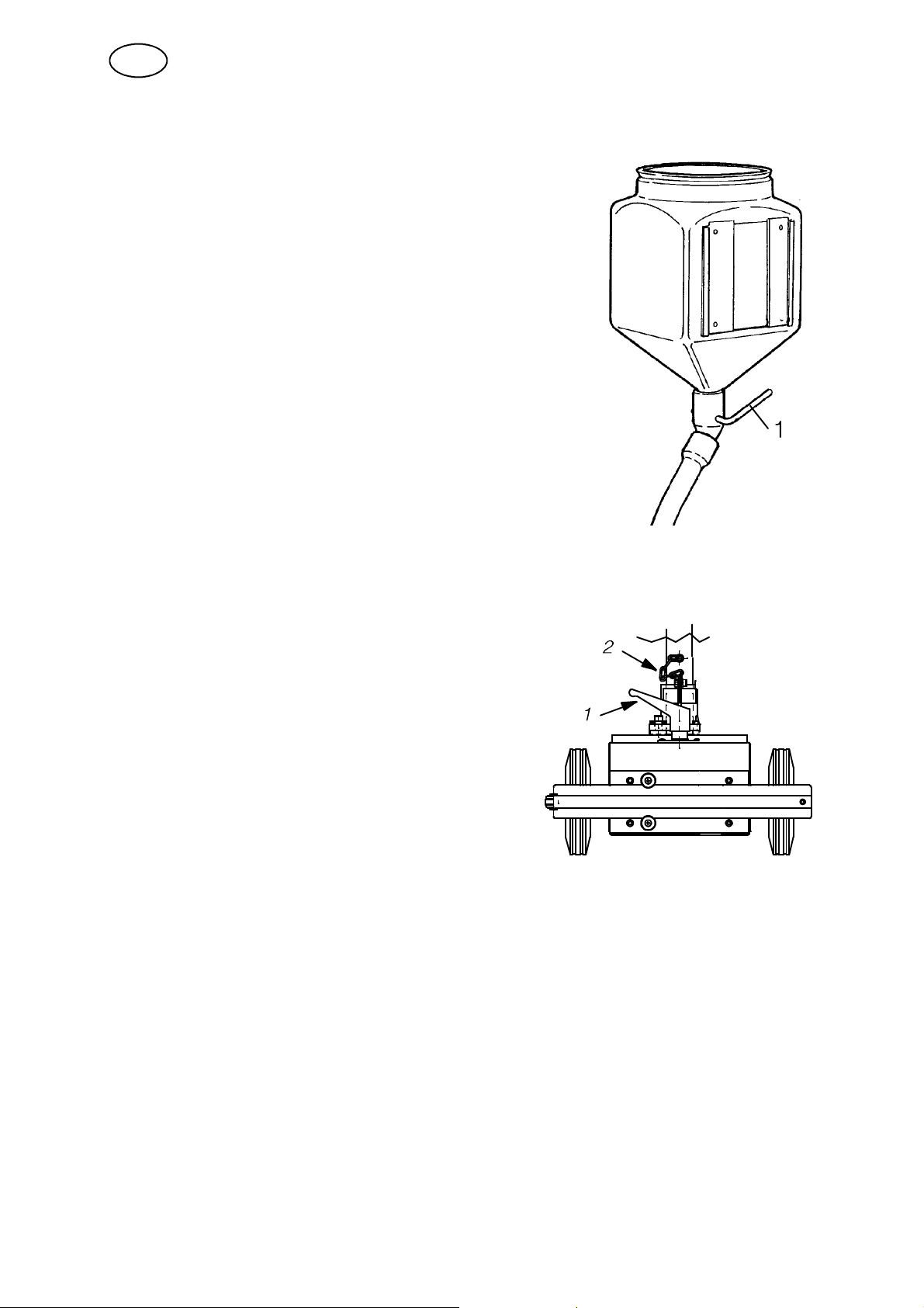
4.6 Refilling with flux powder (Submerged arc welding)
1. Close the flux valve (1) on the flux hopper.
2. Remove the cyclone on the flux recovery unit, if fitted.
3. Fill with flux powder.
NOTE! The flux powder must be dry. Where possible
avoid using agglomerating flux powder outdoors and
in damp environments.
4. Position the flux tube so that it does not become
kinked.
5. Adjust the height of the flux nozzle above the weld so
that the correct amount of flux is delivered.
Flux coverage should be sufficient so that penetration
of the arc does not occur.
4.7 Transportation of the Automatic Welding Machine
S Disengage the wheels by turning the locking lever (1).
S Make sure the safety chain (2) is properly
fastened; this to prevent an accident happening,
if for example the carrier is not adequately
locked to the foot clamp of the carriage.
For transportation through a manhole
the chain can be removed.
4.8 Conversion of A2 TF (Submerged--arc) to MIG/MAG welding
Assemble in accordance with the instructions accompanying the conversion kit.
4.9 Conversion of A2 TF (submerged--arc welding) to Twin--arc
Assemble in accordance with the instructions accompanying the conversion kit.
fhb5o1ea
-- 9 1 --
Page 20

GB
5 MAINTENANCE
5.1 General
Note:
All warranty undertakings given by the supplier cease to apply if the customer
attempts to rectify any faults on the machine during the warranty period.
NB! Before doing any kind of maintenance work, make sure the mains is
disconnected.
For the maintenance of the A2 Welding Control Unit (PEI), see the instruction
manual 0449 331 xxx.
5.2 Daily
S Clean flux and dirt off moving parts of the welding machine.
S Check that the contact tip and all electrical cables are connected.
S Check that all bolted joints are tight and that guides and drive rollers are not
worn or damaged.
S Check the brake hub braking torque. It should not be so low, that the wire reel
continues to rotate when wire feed is stopped and it should not be so great that
the feed rollers slip. As a guide, the braking torque for a 30 kg wire reel should
be 1,5 Nm.
To adjust the braking torque see on page 83.
5.3 Periodic
S Inspect the electrode feed unit’s electrode control, drive rollers and contact tip.
S Replace worn or damaged components.
S Inspect the slides, lubricate them if they are binding.
S Lubricate the chain.
S Tensioning the chain between the trolley’s front and back axles.
S Dismantle the trolley wheels and blanks. Remove the Y flange bearing bolts.
S Tension the chain by moving the trolley’s rear axle parallel in r elation to the
front axle.
S Reassemble in the reverse order.
S Tensioning the chain from the trolley’s front axle to the drive motor and
gearbox.
S Tension the chain by moving the drive motor and gearbox.
fhb5m1ea
-- 9 2 --
Page 21

GB
6 TROUBLESHOOTING
6.1 General
Equipment
S Instruction manual control box A2 Welding Control Unit (PEI).
Check
S that the power supply is connected for the correct mains supply
S that all three phases are supplying the correct voltage (phase sequence is not
important)
S that welding cables and connections are not damaged
S that the controls are correctly set
SSSS
that the mains supply is disconnected before starting repairs
6.2 POSSIBLE FAULTS
1. Symptom Current and voltage readings show large fluctuations.
Cause 1 .1 Contact jaws or nozzle are worn or wrong size.
Action Replace contact jaws or nozzle.
Cause 1 .2 Feed roller pressure is inadequate.
Action Increase pressure on feed rollers.
2. Symptom Wire feed is irregular.
Cause 2 .1 Pressure on feed rollers incorrectly set.
Action Adjust pressure on feed rollers.
Cause 2 .2 Feed rollers wrong size.
Action Replace feed rollers.
Cause 2 .3 Grooves in feed rollers are worn.
Action Replace feed rollers.
3. Symptom Welding cab les overheating.
Cause 3 .1 Poor electrical connection.
Action Clean and tighten all electrical connections.
Cause 3 .2 Cross--sectional area of welding cables too small.
Action Use cables with a larger cross--section or use parallel cables.
7 ORDERING OF SPARE PARTS
Spare parts are ordered through your nearest ESAB representative, see back cover.
When ordering spare parts, please state machine type and number as well as designation and spare part number as shown in the spare parts list on page 113.
This will simplify dispatch and ensure you get the right part.
fhb5f1ea
-- 9 3 --
Page 22
ESAB subsidiaries and representative offices
Europe
AUSTRIA
ESAB Ges.m.b.H
Vienna--Liesing
Tel: +43 1 888 25 11
Fax: +43 1 888 25 11 85
BELGIUM
S.A. ESAB N.V .
Brussels
Tel: +32 2 745 11 00
Fax: +32 2 726 80 05
THE CZECH REPUBLIC
ESAB VAMBERK s.r.o.
Prague
Tel: +420 2 819 40 885
Fax: +420 2 819 40 120
DENMARK
Aktieselskabet ESAB
Copenhagen--Valby
Tel:+4536300111
Fax:+4536304003
FINLAND
ESAB Oy
Helsinki
Tel: +358 9 547 761
Fax: +358 9 547 77 71
FRANCE
ESAB France S.A.
Cergy Pontoise
Tel:+33130755500
Fax:+33130755524
GERMANY
ESAB GmbH
Solingen
Tel: +49 212 298 0
Fax: +49 212 298 204
GREAT BRITAIN
ESAB Group (UK) Ltd
Waltham Cross
Tel: +44 1992 76 85 15
Fax: +44 1992 71 58 03
ESAB Automation Ltd
Andover
Tel: +44 1264 33 22 33
Fax: +44 1264 33 20 74
HUNGARY
ESAB Kft
Budapest
Tel:+3612044182
Fax:+3612044186
ITALY
ESAB Saldatura S.p.A.
Mesero (Mi)
Tel:+3902979681
Fax:+390297289181
THE NETHERLANDS
ESAB Nederland B.V.
Utrecht
Tel: +31 30 248 59 22
Fax: +31 30 248 52 60
NORWAY
AS ESAB
Larvik
Tel:+4733121000
Fax:+4733115203
POLAND
ESAB Sp.z.o.o
Warszaw
Tel: +48 22 813 99 63
Fax: +48 22 813 98 81
PORTUGAL
ESAB Lda
Lisbon
Tel: +351 1 837 1527
Fax: +351 1 859 1277
SLOVAKIA
ESAB Slovakia s.r.o.
Bratislava
Tel:+421744882426
Fax:+421744888741
SPAIN
ESAB Ibérica S.A.
Alcobendas (Madrid)
Tel: +34 91 623 11 00
Fax: +34 91 661 51 83
SWEDEN
ESAB Sverige AB
Gothenburg
Tel:+4631509500
Fax:+4631509222
ESAB International AB
Gothenburg
Tel:+4631509000
Fax:+4631509360
SWITZERLAND
ESAB AG
Dietikon
Tel: +41 1 741 25 25
Fax: +41 1 740 30 55
North and South America
ARGENTINA
CONARCO
Buenos Aires
Tel: +54 11 4 753 4039
Fax: +54 11 4 753 6313
BRAZIL
ESAB S.A.
Contagem--MG
Tel: +55 31 333 43 33
Fax: +55 31 361 31 51
CANADA
ESAB Group Canada Inc.
Missisauga, Ontario
Tel: +1 905 670 02 20
Fax: +1 905 670 48 79
MEXICO
ESAB Mexico S.A.
Monterrey
Tel: +52 8 350 5959
Fax: +52 8 350 7554
USA
ESAB Welding & Cutting Products
Florence, SC
Tel: +1 843 669 44 11
Fax: +1 843 664 44 58
Asia/Pacific
CHINA
Shanghai ESAB A/P
Shanghai
Tel: +86 21 6539 7124
Fax: +86 21 6543 6622
INDIA
ESAB India Ltd
Calcutta
Tel: +91 33 478 45 17
Fax: +91 33 468 18 80
INDONESIA
P.T. Esabindo Pratama
Jakarta
Tel: +62 21 460 01 88
Fax: +62 21 461 29 29
MALAYSIA
ESAB (Malaysia) Snd Bhd
Selangor
Tel: +60 3 703 36 15
Fax: +60 3 703 35 52
SINGAPORE
ESAB Singapore Pte Ltd
Singapore
Tel: +65 861 43 22
Fax: +65 861 31 95
ESAB Asia/Pacific Pte Ltd
Singapore
Tel: +65 861 74 42
Fax: +65 863 08 39
SOUTH KOREA
ESAB SeAH Corporation
Kyung--Nam
Tel: +82 551 289 81 11
Fax: +82 551 289 88 63
UNITED ARAB EMIRATES
ESAB Middle East
Dubai
Tel: +971 4 338 88 29
Fax: +971 4 338 87 29
Representative offices
BULGARIA
ESAB Representative Office
Sofia
Tel/Fax: +359 2 974 42 88
EGYPT
ESAB Egypt
Dokki--Cairo
Tel: +20 2 390 96 69
Fax: +20 2 393 32 13
ROMANIA
ESAB Representative Office
Bucharest
Tel/Fax: +40 1 322 36 74
RUSSIA--CIS
ESAB Representative Office
Moscow
Tel: +7 095 937 98 20
Fax: +7 095 937 95 80
ESAB Representative Office
St Petersburg
Tel: +7 812 325 43 62
Fax: +7 812 325 66 85
Distributors
For addresses and phone
numbers to our distributors in
other countries, please visit our
home page
www.esab.com
ESAB AB
SE--695 81 LAXÅ
SWEDEN
Phone +46 584 81 000
Fax +46 584 123 08
www.esab.com
030210
 Loading...