

Page 1
F-PRO
Feeder Protection Relay
Model 5100
User Manual
Version 4.0 Rev 0
Page 2

Page 3

Preface
Information in this document is subject to change without notice.
© 2016 ERLPhase Power Technologies Ltd. All rights reserved.
Reproduction in any manner whatsoever without the written permission of
ERLPhase Power Technologies Ltd. is strictly forbidden.
This manual is part of a complete set of product documentation that includes
detailed drawings and operation. Users should evaluate the information in the
context of the complete set of product documentation and their particular
applications. ERLPhase assumes no liability for any incidental, indirect or
consequential damages arising from the use of this documentation.
While all information presented is believed to be reliable and in accordance
with accepted engineering practices, ERLPhase makes no warranties as to the
completeness of the information.
All trademarks used in association with B-PRO, F-PRO, iTMU, L-PRO,
ProLogic, S-PRO, T-PRO, TESLA, TESLA Control Panel, Relay Control
Panel, RecordGraph and RecordBase are trademarks of ERLPhase Power
Technologies Ltd.
Windows® is a registered trademark of the Microsoft Corporation.
HyperTerminal® is a registered trademark of Hilgraeve.
Modbus® is a registered trademark of Modicon.
Contact Information
ERLPhase Power Technologies Ltd
Website: www.erlphase.com
Email: [email protected]
Technical Support
Email: [email protected]
Tel: 1-204-477-0591
D02416R04.00 F-PRO 5100 User Manual i
Page 4

Page 5

Table of Contents
Preface ......................................................................................i
Contact Information ...................................................................i
Table of Contents ....................................................................iii
Using This Guide ......................................................................v
Version Compatibility.............................................................. vii
1 Overview ................................................................. 1-1
Front View........................................................................ 1-3
Back View ........................................................................ 1-3
Model Options/Ordering................................................... 1-4
2 Setup and Communications.................................. 2-1
Power Supply................................................................... 2-1
IRIG-B Time Input ............................................................ 2-1
Communicating with the Relay (IED) ............................... 2-2
Using HyperTerminal to Access the Relay’s User
Interface........................................................................... 2-5
Setting the Baud Rate...................................................... 2-7
Accessing the Relay’s SCADA Services.......................... 2-8
Communication Port Details ............................................ 2-9
Maintenance Menu ........................................................ 2-12
Firmware Update ........................................................... 2-13
3 Using the IED (Getting Started) ............................ 3-1
Start-up Sequence........................................................... 3-1
Front Panel Display.......................................................... 3-2
Terminal Mode ................................................................. 3-5
View, Change or Service Login........................................ 3-9
Breaker Login................................................................. 3-13
Metering Data ................................................................ 3-14
4 Protection Functions and Specifications ............ 4-1
Protection and Recording Functions................................ 4-1
Demand Metering .......................................................... 4-17
Accumulated Energy (kWh, kVARh metering)............... 4-20
Recording Functions...................................................... 4-26
Logging Functions.......................................................... 4-28
5 Offliner Settings Software..................................... 5-1
Introduction ...................................................................... 5-1
Installing PC Software...................................................... 5-2
D02416R04.00 F-PRO 5100 User Manual iii
Page 6

Table of Contents
Offliner Features .............................................................. 5-2
Handling Backward Compatibility .................................... 5-4
RecordBase View Software ............................................. 5-5
Main Branches from the Tree View.................................. 5-6
Settings From a Record ................................................. 5-19
6 Testing the F-PRO Functions................................ 6-1
7 Installation .............................................................. 7-1
Physical Mounting............................................................ 7-1
AC and DC Wiring............................................................ 7-1
Communication Wiring..................................................... 7-1
Appendix A IED Specifications .............................................A-1
Distance Element Operating Time Curves at Nominal
Frequency ........................................................................A-4
Frequency Element Operating Time Curves....................A-5
Appendix B IED Settings and Ranges..................................B-1
Appendix C Hardware Description .......................................C-1
Appendix D Event Messages ...............................................D-1
Appendix E Modbus RTU Communication Protocol.............E-1
Appendix F DNP3 Communication Protocol......................... F-1
Appendix G Mechanical Drawings........................................G-1
Appendix H Rear Panel Drawings ........................................H-1
Appendix I AC Schematic Drawing........................................ I-1
Appendix J DC Schematic Drawing.......................................J-1
Appendix K Function Logic Diagram ....................................K-1
Appendix L F-PRO Setting Example .................................... L-1
Setting Examples ............................................................. L-2
Switching Setting Groups................................................. L-5
Index..........................................................................................I
iv F-PRO 5100 User Manual D02416R04.00
Page 7
Using This Guide
This User Manual describes the installation and operation of the F-PRO feeder
protection relay. It is intended to support the first time user and clarify the details of the equipment.
The manual uses a number of conventions to denote special information:
Example Describes
Start>Settings>Control Panel Choose the Control Panel submenu in the Set-
Right-click Click the right mouse button.
Recordings Menu items and tabs are shown in italics.
tings submenu on the Start menu.
service User input or keystrokes are shown
Text boxes similar to this one Relate important notes and information.
.. Indicates more screens.
Indicates further drop-down menu, click to display list.
Indicates a warning.
in bold.
D02416R04.00 F-PRO 5100 User Manual v
Page 8

Page 9

Version Compatibility
This chart indicates the versions of Offliner Settings, RecordBase View and
the User Manual which are compatible with different versions of F-PRO firmware.
RecordBase View and Of
lier versions of records and setting files. You can use RecordBase View to view
records
create and edit older setting file versions.
Minor releases (designated with a letter suffix
compatibility as their base version. For example. F-PRO firmware v3.1c and
Offliner Settings v3.1a are compatible.
produced by any version of F-PRO firmware and Offliner Settings can
F-PRO Firmware/Software Compatibility Guide
fliner Settings are backward compatible with all ear-
- e.g. v3.1a) maintain the same
F-PRO
Firmware
v4.0 2 4000 v1.0 or greater
v3.0 2 4000 v1.0 and greater
v3.0 2 v3.0 or greater
v2.0a 2 v2.0 or greater
v2.0 2 v2.0 or greater
v1.0d 1 v1.0b or greater
v1.0c 1 v1.0a or greater
v1.0b 1 v1.0a or greater
v1.0a 1 v1.0a or greater
v1.0 1 v1.0 or greater
Setting File
Ver sio n
Compatible Of
fliner Settings
Please contact ERLPhase Customer Service for complete Revision History.
D02416R04.00 F-PRO 5100 User Manual vii
Page 10

Page 11
1 Overview
F-PRO Feeder Protection Relay
Offline Mode - Settings Software
Online Mode - Terminal Mode
F-PRO
Feeder Protection
Model 5100
Port 1
Date &
Time
View
Readings
View
Logs
Prev
Next
Targ et
Clear
Targ et
1999 JUN 07
Relay Functional
IRIG-B Functional
Service Required
Test Mode
Alarm
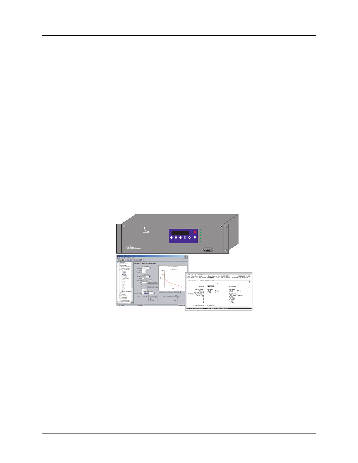
The F-PRO (model 5100) is a microprocessor-based relay providing comprehensive directional overcurrent protection, reclosing, mete
ring, breaker moni-
toring and recording functions suitable for medium and low voltage lines.
F-PRO has two working modes—online and off
line. In the online mode you
can use any communication software package (e.g. Procomm or HyperTerminal) to connect to the F-PRO using VT100 terminal emulation. In online mode
y
ou can:
• change and review relay
settings
• view event and metering information
• initiate and retrieve recordings, and retrieve setti
In offline mode you can use Offliner Se
ttings and RecordBase View software
ngs
to:
• create and review relay settings
• analyze fault waveforms
• store records
D02416R04.00 F-PRO 5100 User Manual 1-1
In addition to the protection functions F-PRO provides fault recording (96
sample/cycle) to facilitate analysis of the power system after a disturbance has
taken place. The triggers for fault recording are established by programming
the output matrix and allowing any internal relay function or any external input
to initiate recording.
The primary protection provided is overcurrent based. A library for these
overcurrent f
unctions provides commonly used IEEE and IEC inverse curves.
Because the curves are equation-driven, you can choose to enter an equation
parameter directly, creating other overcurrent shapes as needed. All
overcurrent functions are provided with directional control, if required, using
the ERLPhase method of positive sequence control.
Page 12
1 Overview
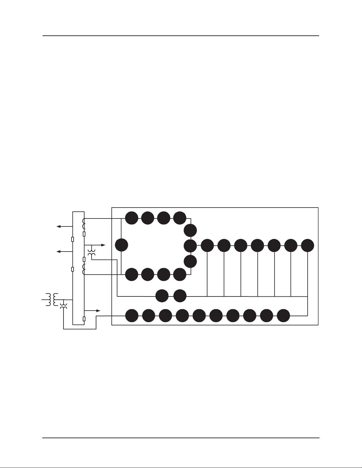
To provide a complete package of protection and control, F-PRO provides other functions such as:
• ring bus capability to protect and monitor
lines connected to ring schemes
Current inputs are labelled Main and Aux inputs to denote the breaker ring
current inputs. Use F-PRO with straight single breaker line schemes by using the main current inputs
• breaker failure detection and monitoring
• 2 completely dedicated four shot reclosers devices 79 Main and 79 Aux to
control line re
closing needs along with device 25C Sync Check/Dead Bus/
Dead Line supervision
• low set overcurrent functions for e
ach breaker as well as for the summated
line currents that include phase, neutral and negative sequence functions
• Watt, VAR flow detectors as well a
s undervoltage, overvoltage and over/
under frequency functions (Freq ROC) to provide protection for issues
such as inter-tie protection needs
• ProLogic provide a flexible way to addres
s special protection needs. Ten
ProLogic statements are provided
• Breaker Logic, Group Logic, Demand Metering
Source
Feeder
Feeder
PT (3 ph)
Analog Inputs
4 Analog Voltages
1 Three-phase Input
1 Single-phase Input
6 Analog Currents
2 Three-phase Inputs
Ring Bus
CT 2
CT 1
Aux.
PT (1 ph)
Main
Protected
Feeder
50LS-2
50LS-1
THD
50LS-1
50LS-2
Feeder
Outputs
12 Output Contacts
1 Relay Inoperative
Alarm Contact
Inputs
9 External Inputs
59-1 59-2 27-1 27-2
Trend Recording (Primary)
Real Power (MW In and Out)
Reactive Power (MVAR In and Out)
3 Phase Voltages (Va, Vb, Vc)
3 Phase Currents (Ia, Ib, Ic)
Real Energy (MWh In and Out)
Reactive Energy (MVARh In and Out)
THD Level (%)
System Frequency
Figure 1.1: F-PRO Line Diagram
50BF
50BF
Rec
79Aux
79
Main
25C
Rec
Σ
Rec
50/51/
67
60 81-1
Fault Recording
4 Voltages
6 Currents
97 Unique Events
50N/51N
67
46/
50/51/
67
81-2 81-3
21P
Metering
81-4
Metering (Front Display)
Primary Pos. Sequence Volts, Amps,
Primary Watts and VARs
Frequency
THD (Total Harmonic Distortion)
PF (Power Factor)
Primary Phase Voltage, Current, Phase
Angle (A, B, C)
Peak Demand MW, MVAR In and
Out Phase Currents
Energy Values MWh In and Out
MVARh In and Out
3I0
32P 32Q
Rec
1-2 F-PRO 5100 User Manual D02416R04.00
Page 13

Front View
1. Front display of time, alarms, relay target and metering
2. Relay target LED (red)
3. LEDs indicating status of relay
4. Communications serial Port 1 for laptop computer
5. Clear target push button
6. Push buttons to manipulate information on LCD display
F-PRO
Feeder Protection Relay
Model 5100
Relay Functional
IRIG-B Functional
Service Required
Test Mode
Alarm
Port 1
NextView
Readings
View
Logs
Previous
456
Target
Clear
Target
2000 Jan 07 11:49:54
Date &
Time
1 2
3
VA VB VC N
Main AC Line Currents
Main AC Volts
Power Supply
300 301 302 303 305 306 307 308 309 310 312311 313 314 315 316 317 318 319 320 321 322 323 324 326 327 328 329 330 331 332 333325
Case
Ground
231 232 233
Relay
Inoperative
Output Relay Contracts
200 201 202 203 204 205 206 207 208 209 210 212211 213 214 215 216 217 218 219 220 221 222 223 224 226 227 228 229 230225
External
Inputs
100 101 102 103 104 105 106 107 108 109 110 112111 113 114 115 116 117
+ - + - + - + - + - + - + - + - + -
234 235
Port 4
Unused
Port 3
SCADA
IRIG-B
1 2 3456 987
Out 1 Out 2 Out 3
Out 4 Out 5 Out 6 Out 7 Out 8 Out 9 Out 10
Out 11
Out 12
I1 A I1 B I1 C I2 A I2 B
I2 C
I3 A I3 B I3 C I4 A I4 B
+ -
VA VB
I4 C
VC
7. Port 5 - 10BaseT Ethernet Port/Internal Modem (optional)
8. External clock, IRIG-B modulated or unmodulated
9. Port 2 - Direct/Modem RS-232 Port
10. Port 3 - SCADA
11. Port 4 - unused
12. Case ground
13. 9 programmable external inputs (1 to 9)
14. This row contains 2 distinct areas from left to right:
12 programmable output relay contacts and relay inoperative contact
15. This row contains 3 distinct areas from left to right:
6 ac current inputs
4 ac voltage inputs
Power supply
13
14
15
Output
Contacts
In. Freq.
Aux.AC Line Currents AC Currents Inputs
Nominal
48-250 Vdc
120 Vac
Aux. AC Volts
Unused
N
Sync AC
Volts
125Vdc125Vdc 125Vdc 125Vdc 125Vdc 125Vdc 125Vdc 125Vdc 125Vdc
Port 2
Direct/Modem
Port 5
VN
Unused
7 8 9 10 11 12
1 Overview
Figure 1.2: F-PRO Front View
Back View
Figure 1.3: F-PRO Back View
D02416R04.00 F-PRO 5100 User Manual 1-3
Page 14

1 Overview
AC Current and Voltage Inputs
F-PRO is provided with terminal blocks for up to 6 ac currents and 4 phase-toneutral voltages.
Each of the current input circuits has polarity (•) marks.
A complete schematic of current and voltage circuits is shown, for details see
“AC Schematic Drawing” in Appendix I and “DC Schematic Drawing”
in Appendix J.
External Inputs The F-PRO relay contains 9 programmable external inputs. External dc voltage
of either 48/125 volts or 125/250 volts nominal are possible depending on the
range provided.
Output Relay Contacts
The F-PRO relay has 12 output relay contacts. Each contact is programmable
and has breaker tripping capability. All output contacts are isolated from each
other. The output contacts are closed for a minimum of 100 ms after operation.
Relay Inoperative Alarm Output
If the relay becomes inoperative, then the Relay Inoperative Alarm output contact closes and all tripping functions are blocked.
Model Options/Ordering
F-PRO is available as a horizontal mount, for details see “Mechanical Drawings” in Appendix G.
F-PRO is available with an internal modem card or internal network card.
The CT inputs are 1 A nominal or 5 A nominal. The external inputs are 48/125
Vdc or 125/250 Vdc. The system base frequency is either 50 Hz or 60 Hz.
All of the above options must be specified at the time of ordering.
1-4 F-PRO 5100 User Manual D02416R04.00
Page 15

2 Setup and Communications
Power Supply
A wide range power supply is standard. The nominal operating range is 48–250
Vdc, 120 Vac, 50/60 Hz. To protect against possible short circuit in the supply
use an inline fuse or circuit breaker with a 5 A rating. Make the chassis ground
connection to ensure proper operation and safety.
There are no power switches on the relay. When the
ed, the relay starts its initialization process and takes about
plete showing the green Relay Functional LED.
Case Grounding You must ground the relay to station ground using the case-grounding terminal
at the back of the
View on page 1-3.
WARNING!
To ensure safety and proper operation you must connect the relay to
station ground using the rear grounding terminal on the relay.
the
relay, for details see for details see Figure 1.3: F-PRO Back
power supply is connect-
40 seconds to com-
IRIG-B Time Input
The relay is equipped to handle modulated or unmodulated GPS satellite time
IRIG-B signals. The IRIG-B time signal is connected to the BNC connection
on the back of the relay. When the IRIG-B signal is provided to the relay and
is enabled in the settings through the user interface, the IRIG-B functional LED
comes on and the relay clock is referenced to this signal. No settings are required to differentiate between modulated or unmodulated signals; this is automatically detected by the relay.
You enable or disable the IEEE 1344 extension in
Utilities>Setup>Time, for details see “Utilities” on page 3-14. The enabled
mode allows the year to be received from the IRIG-B signal. If the available
IRIG-B signal
Ground the relay even when testing.
Do not rely on the rack mounting screws to provide case grounding.
the terminal mode settings
has no year extension, this setting should be disabled.
D02416R04.00 F-PRO 5100 User Manual 2-1
Page 16
2 Setup and Communications
Communicating with the Relay (IED)
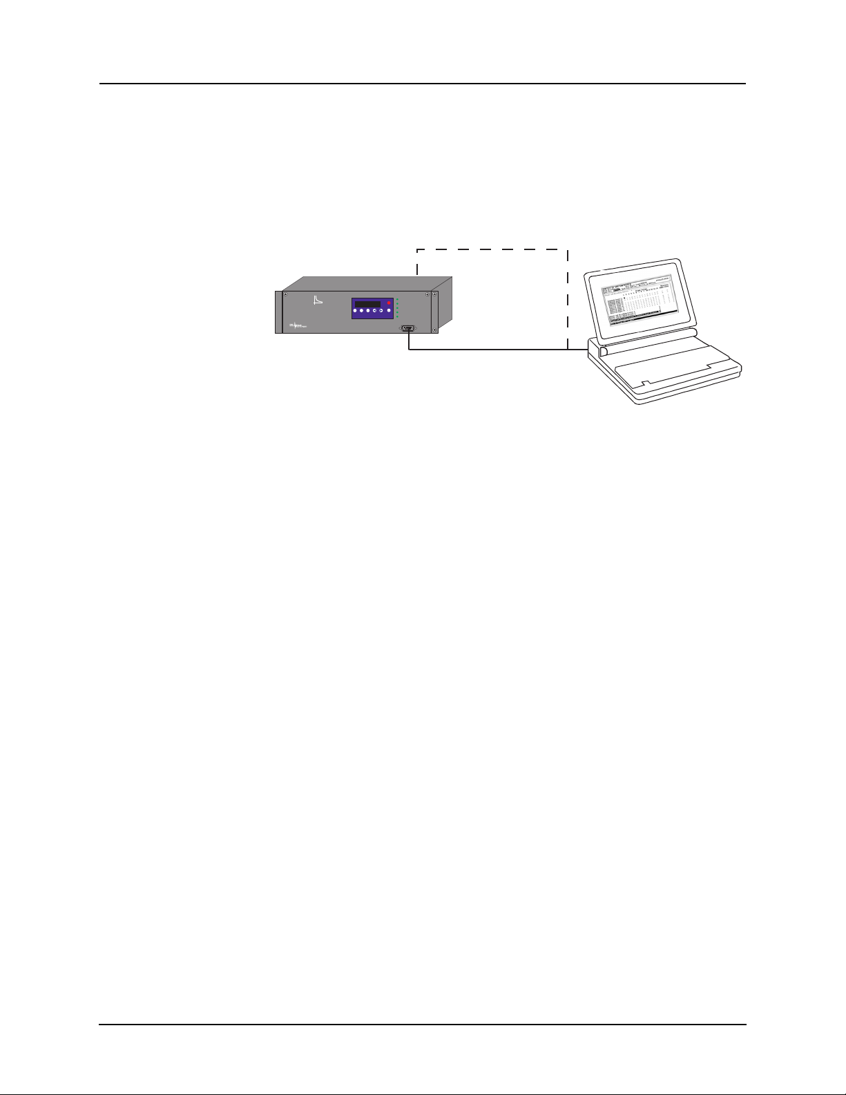
You can connect to the relay to access its user interface and SCADA services:
• direct serial link (user interface and SCADA)
• external or internal modem link (user interface only)
• ethernet network link (user interface and SCADA)
Direct Serial Link
Port 2 - direct/modem
F-PRO
Feeder Protection
Model 5100
Date &
Readings
Time
1999 JUN 07
View
View
Prev
Logs
Port 1
Relay Functional
IRIG-B Functional
Target
Service Required
Test Mode
Next
Clear
Target
Alarm
Port 1
Serial Extension Cable
Relay Port 1 or rear Port 2
to PC Serial Port
Laptop PC
Figure 2.1: Direct Serial Link
The relay has three serial ports that provide direct access to its user interface
and SCADA services.
All of the relay’s serial ports (Ports 1, 2 and 3) are configured as EIA
RS-232
Data Communications Equipment (DCE) devices with female DB9 connectors. This allows them
dard straight-through male-to-female serial cable, for pin-out,
to be connected directly to a PC serial port with a stan-
for details see
“Communication Port Details” on page 2-9.
The relay’s user interface is accessed through a
ulation program running on a PC. To create a direc
lay and your computer, connect the seri
al cable (provided) between your
standard VT-100 terminal em-
t serial link between the re-
computer's serial port and Port 1 on the relay’s front panel. Port 2 on the relay’s
back panel can also be used for direct serial access, provided the port is not
configured for modem use. When connected, run the terminal emulation software on your computer to establish the communication link, for details see
“Using HyperTerminal to Access the Relay’s User Interface” on page 2-5.
The relay’s Modbus and DNP3 SCADA services can be accessed via a direct
serial
link to Port 3 on the relay's back panel, for details see “Accessing the Re-
lay’s SCADA Services” on page 2-8.
2-2 F-PRO 5100 User Manual D02416R04.00
Page 17
Modem Link -
External
Modem
Telephone
System
Analog
Telephone
Line
Modem Adapter
Supplied by ERLPhase
DB-9-Male-Male
Modem Cable
(as supplied with modem)
Modem Adapter
Port 2 - Direct/Modem
Analog
Telephone
Line
F-PRO
Feeder Protection
Model 5100
Port 1
Date &
Time
View
Readings
View
Logs
Prev
Next
Target
Clear
Target
1999 JUN 07
Relay Functional
IRIG-B Functional
Service Required
Test Mode
Alarm
External
2 Setup and Communications
Modem Cable
(as supplied with modem)
Modem Adapter
Port 2 - Direct/Modem
F-PRO
Feeder Protection
Model 5100
1999 JUN 07
Target
Next
View
View
Prev
Date &
Clear
Readings
Logs
Time
Target
Relay Functional
IRIG-B Functional
Service Required
Test Mode
Alarm
Port 1
External
Analog
Telephone
Line
Telephone
System
Analog
Telephone
Line
Modem
Modem Adapter
Supplied by ERLPhase
DB-9-Male-Male
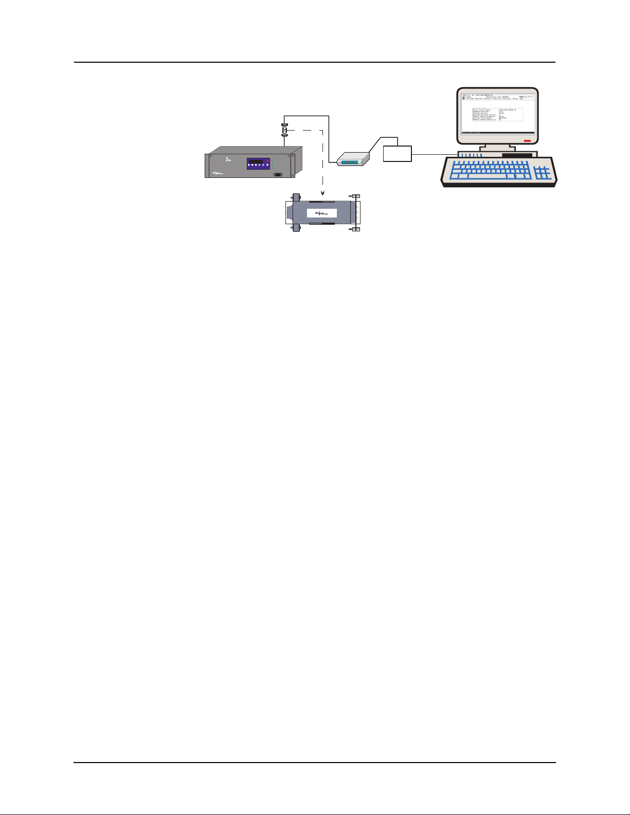
Figure 2.2: External Modem Link
The relay’s user interface can also be accessed through a telephone link between the relay and your computer, using an external modem.
Connect the serial port on the external modem to
the Port 2 on the relay's back
panel. Both devices are configured as RS-232 DCE devices with female connectors, so the cable between the relay a
nd the modem requires a crossover and
a gender change. Alternatively, you can use the ERLPhase modem port adapter
provided with the relay to make Port 2 appear the same as a PC’s serial port. A
standard modem-to-PC serial cable can then be used to connect the modem and
the relay, for pin-out details see “Communication Port Details” on page 2-9.
Connect the modem to an analog telephone line or switc
h using a standard RJ-
11 connector.
To work with a modem, the relay’s Port 2 must be appropriately configured.
Log into the rel
ay through a direct serial link, go to the Utilities>Setup>Ports
screen, and set the Port 2 Modem option to Yes. The Baud Rate should be set
as high as possible - most modems will handle 57,600 bps. The Initialize setting lets you set the control
nection session. The factory defaults are: “M0S0=0&B1” for
codes sent to the modem at the start of each con-
an external
modem and “M0S0=0” for an internal modem.
D02416R04.00 F-PRO 5100 User Manual 2-3
Page 18
2 Setup and Communications
Modem Link Internal
Network Link
Port 5 - RJ-11 modem
F-PRO
Feeder Protection
Model 5100
1999 JUN 07
Next
View
View
Prev
Date &
Readings
Logs
Time
Analog
Telephone
Line
Relay Functional
IRIG-B Functional
Target
Service Required
Test Mode
Clear
Target
Alarm
Port 1
Telephone
System
Analog
Telephone
Line
Desktop Computer
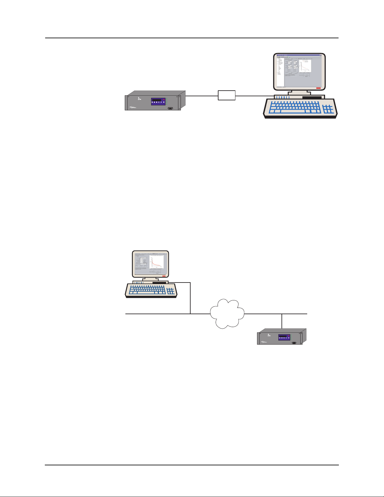
Figure 2.3: Internal Modem Link
The relay’s user interface can also be accessed through a telephone link between the relay and your computer using an opti
onal internal modem. If the
modem has been installed, Port 5 on the rear panel will be labelled “INTERNAL MODEM.”
Connect the relay’s Port 5 to an analog telephone
line or switch using a stan-
dard RJ-11 connector.
When an internal modem is installed, the relay’
s Port 2 is used to interface to
the modem internally. Appropriate Port 2 settings are configured at the factory
when the internal modem is installed. The factory defaults are: “M0S0=0&B1”
for an external modem and “M0S0=0” for an internal modem.
PC with TCP/IP
TCP/IP
Network
10BaseT
Port 5 - RJ-45
Network
F-PRO
Feeder Protection
Model 5100
Relay Functional
IRIG-B Functional
1999 JUN 07
Target
Service Required
Test Mode
Next
View
View
Prev
Date &
Clear
Readings
Logs
Time
Target
Alarm
Port 1
Figure 2.4: Network Link
You can access both the relay’s user interface and DNP3 SCADA services simultaneously through the same network port with an
optional Ethernet TCP/IP
LAN link. If the Ethernet option has been installed, Port 5 on the rear panel will
be labelled “NETWORK.”
The user interface accessed through the LAN is the same as that available
through
a direct serial connection or a modem link, but requires the use of a
Telnet client on your PC. The HyperTerminal program, which is included in
Windows XP and is also available separately as HyperTerminal PE, provides
Telnet services. To select Telnet, go to HyperTerminal’s Properties dialog box
and set the Connect Using field to TCP/IP (Winsock). If this option is not avail-
2-4 F-PRO 5100 User Manual D02416R04.00
Page 19

2 Setup and Communications
able in the pick list, you require a newer version of HyperTerminal (v1.2 or
greater). Alternatively, you can use any Telnet program that fully supports VT100 terminal emulation and z-modem file transfer.
DNP3 SCADA services can also be accessed over the LAN, for details see
“Accessing the Relay’s SCADA Services” on page 2-8.
Connect Port 5 to the Ethernet LAN using an appropriate 10BaseT cable with
an RJ-45 connector. The relay supports 10 Mbit Ethernet, although a dual
speed 10/100 Ethernet hub or switch can be used.
By default, the relay is assigned an IP address of 192.168.1.100. If this address
is not suitable, it may be modified using the relay’s , for details see
“Using Hy-
perTerminal to Access the Relay’s User Interface” on page 2-5.
Using HyperTerminal to Access the Relay’s User Interface
Change settings, view measured values and retrieve data from the relay using
its user interface. This section describes how to configure a standard Windows
VT-100 terminal program on your PC for use with the relay.
The computer must be connected to the relay by one of its serial, modem or
Ethernet communication ports, for details see
(IED)” on page 2-2.
The relay user interface is accessed using a standard VT-100 terminal style
program on your computer eliminating the need for specialized user interface
software. Any terminal program that fully supports VT-100 emulation and pro
vides z-modem file transfer services can be used. The HyperTerminal program
is used here as an example.
Configure your terminal program as described in the table below and link it to
the appropriate serial port, modem or TCP/IP socket on your computer.
“Communicating with the Relay
-
Terminal Program Setup
Baud rate
Data bits
Parity
Stop bits
Flow control
Function, arrow
and control keys
Emulation
D02416R04.00 F-PRO 5100 User Manual 2-5
For a direct serial link, the baud rate must match that of the relay serial
port.
For a modem link, the baud rate refers only to the link between your
computer and its own modem.
Refer to “Setting the Baud Rate” on page 2-7 for further information
8
None
1
Hardware or Software.
Hardware flow control is recommended. The relay automatically
supports both on all its serial ports.
Terminal keys
VT100
Page 20
2 Setup and Communications
Terminal Program Setup
Font Use a font that supports line drawing (e.g. Terminal or MS Line Draw).
If the menu appears outlined in odd characters, the font you have
selected is
not supporting line drawing characters.
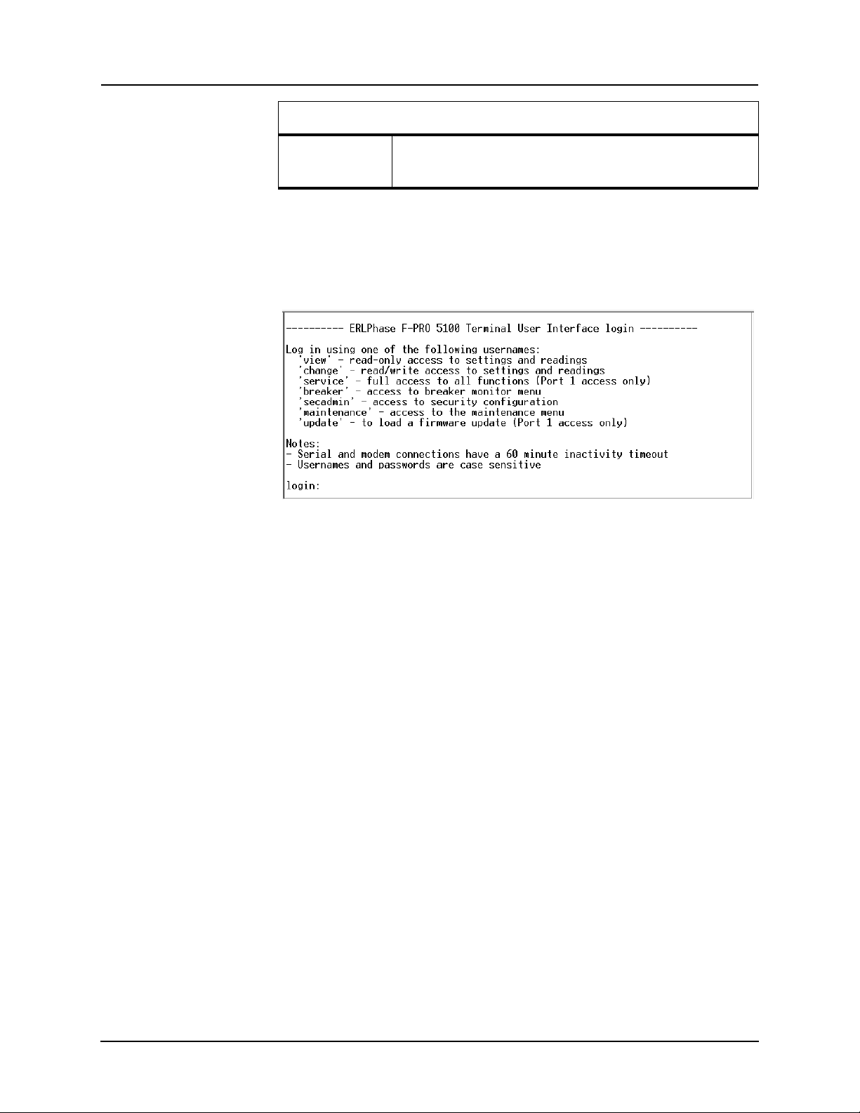
To initiate the connection with the relay, use HyperTerminal’s Call>Connect
function.
When the connection is established, press Enter in the
terminal window to
bring up the following login prompt:
Instructions on logging in and running the user interface are given in “Terminal
Mode” on page 3-5.
If you see incorrect characters on a direct
serial connection, it may mean there
is a mismatch between the relay’s baud rate and that of the PC.
Ending a User
Inte
rface Session
Use the Quit function in the relay’s user menu to end a session. This will close
the interface and require the next user to log in to the relay.
The relay automatically ends a session when it detec
ts the disconnecting of a
direct serial cable or a modem hang-up. For other types of connections (e.g. serial switches or Ethernet) you are advised to
use the Quit function to ensure the
interface is closed and login protection is activated.
2-6 F-PRO 5100 User Manual D02416R04.00
Page 21

2 Setup and Communications
Setting the Baud Rate
The baud rate of the relay's serial ports can be shown on the relay’s
front panel display. From the main Date & Time display, press the
Next button.
Direct Serial Link For a direct serial connection, both the relay and your computer must be set to
the
same baud rate.
To change the baud rate of a relay serial port:
1 Access the relay’s user interface through any of the available ports
2 Log in to the user interface and go to the Utili
details see “Terminal Mode” on page 3-5.
3 Select the desired baud rate for the appropriate port by toggling through the
options using
the Space or Enter keys. Save the new setting with the F2 key.
The message “New communications settings loaded” will appear.
The new baud rate will be used on that
To change the baud rate on your computer’s serial port:
port the next time you log in to it.
1 From within HyperTerminal, bring up the Properties dialogue, press the
Configure button and set the baud rate field to the desired value.
2 Save the changes.
ties>Setup>Ports menu, for
Modem Link Unlike a direct serial link, the baud rates for a modem link do not have to be
the same on your computer and on the relay. The modems automatically negotiate an optimal baud rate for their communication.
The baud rate set on the relay only affe
nicates with the modem. Similarly, the
cts the rate at which the relay commu-
baud rate set in HyperTerminal only affects the rate at which your computer communicates with its modem. Details
on how to s
et these respective baud rates are described above, except that you
modify the Port 2 baud rate on the relay and the properties of the modem in HyperTerminal.
D02416R04.00 F-PRO 5100 User Manual 2-7
Page 22

2 Setup and Communications
Accessing the Relay’s SCADA Services
The relay supports DNP3 (Level 2) and Modbus SCADA protocols as a standard feature on all relays. DNP3 is available through a
Ethernet LAN on top of either TCP or UDP protocols. The Modbus implementation supports both RTU (binary) or A
direct serial link.
The relay’s Port 3 is dedicated for use with
Port 3 uses standard RS-232 signalling. An external RS-232<->RS-485 converter can also be used to connect to an RS-485 network.
For details on connecting to serial Port 3 see “Communicating with the Relay
(IED)” on page 2-2 and “Communication Port Details” on page 2-9.
The DNP3 protocol can also be run across the optional Ethernet LAN. Both
DNP o
to the Ethernet LAN see “Network Link” on page 2-4.
Complete details on the Modb
the Appendices, “Modbus RTU Communication Protocol” in Appendix E and
“DNP3 Communication Protocol” in Appendix F respectively.
ver TCP and DNP over UDP are supported. For details on connecting
us and DNP3 protocol services can be found in
direct serial link or the
SCII modes and is available through a
Modbus or DNP3 serial protocols.
Protocol Selection To select the desired SCADA protocol, login
access the Utilities>Setup>SCADA menu. Select the protocol and set the corresponding parameters.
The DNP3 LAN/WAN - TCP and UDP options are only available if the
ptional Ethernet LAN port installed.
rs are set using the Utilities>Setup>Ports
Communication Parameters
unit has an o
Port 3’s communication paramete
menu in relay’s user interface. Both the baud rate and the parity bit can be configured. The number of data bits and stop bits are
the selected SCADA protocol. Modbus ASCII uses 7 data bits. Modbus RTU
and DNP Serial use 8 data bits. All protocols use 1 stop bit except in the case
where either Modbus protocol is used with no parity; this uses 2 stop bits, as
defined in the Modbus standard.
Diagnostics Protocol monitor utilities are available
nication difficulties such as incompatible
to assist in resolving SCADA commu-
baud rate or addressing. The utilities
can be access through the Maintenance user interface, for details see “Maintenance Menu” on page 2-12.
to the relay’s user interface and
determined automatically by
2-8 F-PRO 5100 User Manual D02416R04.00
Page 23

Communication Port Details
Port Location Function
1 Front Panel RS-232 Data Communication Equipment (DCE) female DB9.
2 Rear Panel RS-232 DCE female DB9.
3 Rear Panel RS-232 DCE female DB9.
2 Setup and Communications
Used for user interface access thro
Default Setting: 38,400 baud, 8 data bits, no parity, 1 stop bit.
Used for:
• User interface access thr
• User interface access through an external modem. The optional
ERLPhase Mode
nal Equipment (DTE) to simplify co
modem.
Default Setting: 9,600 baud, 8 data bits, no parity, 1 stop bit.
Port 2 is disabled if the relay is equipped with an internal modem
see Port 5).
(
Used for SCADA communication.
Default Setting: 9,600 baud, 8 data bits, no parity, 1 stop bit.
m Adapter converts this port to a Data Termi-
ugh a direct serial connection.
ough a direct serial connection.
nnection to an external
4 Rear Panel Not used
5 Rear Panel RJ-11/RJ-45 receptacle.
When equipped with optional internal modem:
• Used for user interface access through modem.
When equipped with optional internal Ethernet card:
• User interface access.
• DNP SCADA access.
Default Ethernet IP address: 192.168.1.100.
D02416R04.00 F-PRO 5100 User Manual 2-9
Page 24
2 Setup and Communications
Signal Name
DCD 1
RxD 2
TxD 3
DTR 4
Common 5
DSR 6
RTS 7
CTS 8
No connection 9
Direction
PC<-> Relay
Pin # on the Relay
Port
Notes:
• Relay is DCE, PC is DTE
• Pins 1 and 6 are tied together internal to the relay
Male DB-9 Cable End for Relay
Port
Female DB-9 Cable End for
Computer Port
Pin # on Cable Pin # on Cable
1 1
2 2
3 3
4 4
5 5
6 6
7 7
8 8
9 9
2-10 F-PRO 5100 User Manual D02416R04.00
Page 25

2 Setup and Communications
Signal Name
DCD 1
RxD 2
TxD 3
DTR 4
Common 5
DSR 6
RTS 7
CTS 8
No connection 9
Direction
Modem <-> Relay
Pin # on the Modem
Ad
apter
Notes:
• Relay (with modem adapter) is DTE,
modem is DCE
• Pins 1 and 6 are tied together internal to the relay
D02416R04.00 F-PRO 5100 User Manual 2-11
Page 26
2 Setup and Communications
Maintenance Menu
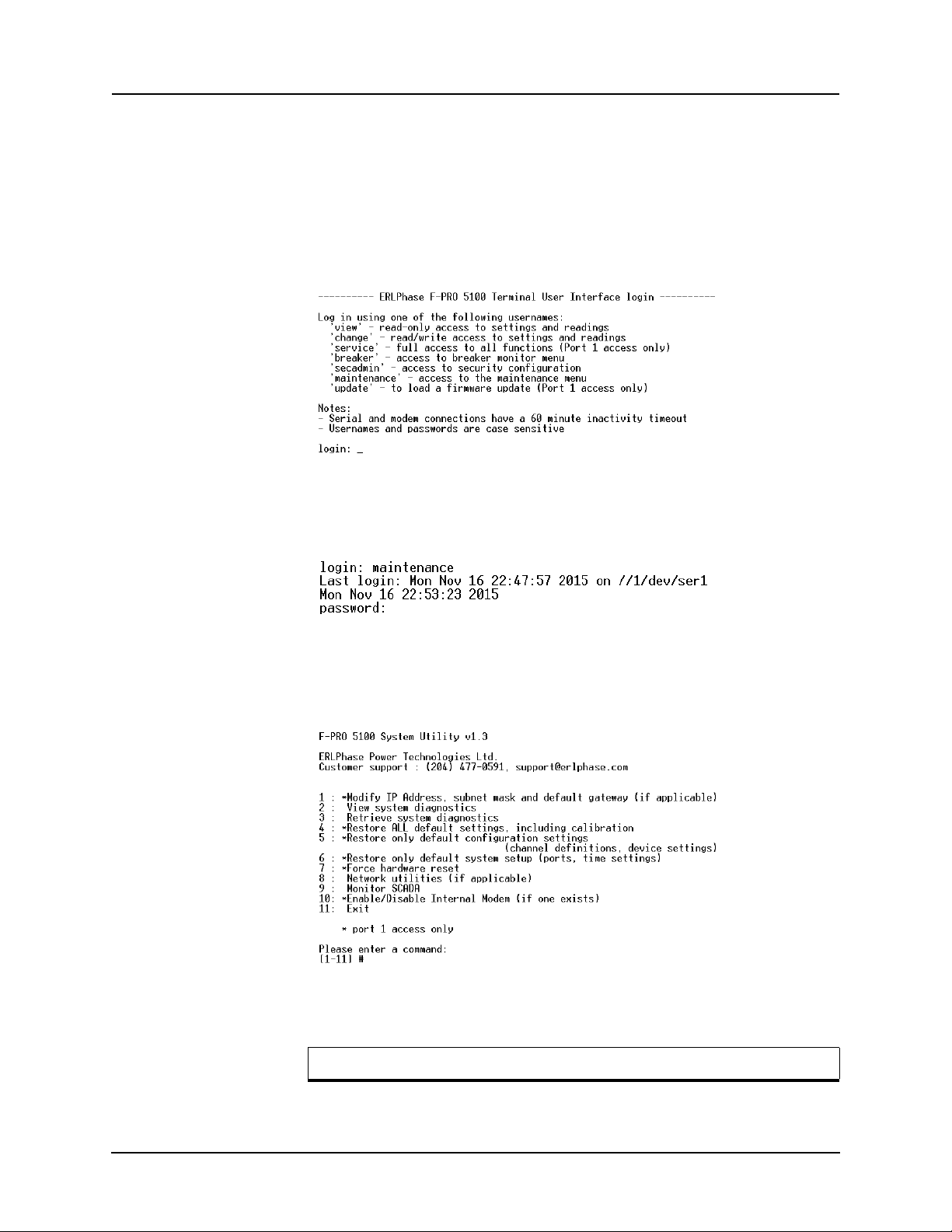
The relay has a Maintenance Menu that can be accessed by connection through
a VT-100 terminal emulator (such as the HyperTerminal program). Using either direct serial or modem connection:
1 Use the terminal program to connect to
2 Select Ent
Figure 2.5: Login prompt
3 Login as “maintenance” in lower case.
4 Relay responds with "password" prompt.
the serial port, either through direct
serial link or modem.
er, the relay responds with a login prompt.
Figure 2.6: Maintenance password prompt
5 Enter password.
6 A menu appears as below.
Figure 2.7: Maintenance menu
Commands 1, 4, 5, 6, 7 and 10 are Port 1 access only.
2-12 F-PRO 5100 User Manual D02416R04.00
Page 27
2 Setup and Communications
Firmware Update
Modify IP address Modifies the LAN IP address when equipped with an
View system diagnostic Displays the internal status log.
Retrieve system diagnostics Automatically packages up the inter
Restore settings Use this menu to force the system back to default values, if
Force hardware reset Manually initiates a hardware reset. Note that the communi-
View network statistics View IP, TCP and UDP statistics when equipped with inter-
Monitor SCADA Shows real time display of SCADA data.
Enable/disable Modem Enables or disables the internal modem.
optional internal 10BaseT Ethernet card.
nal status log plus set-
ting and setup information and downloads it in compressed
to your computer. This file can then be sent to our cus-
form
tomer support to help diagnose a problem.
spect a problem due to the unit’s settings, calibration
you su
and/or setup parameters.
cation link is immediately lost and cannot be re-established
e unit completes its start-up.
until th
nal 10BaseT Ethernet card.
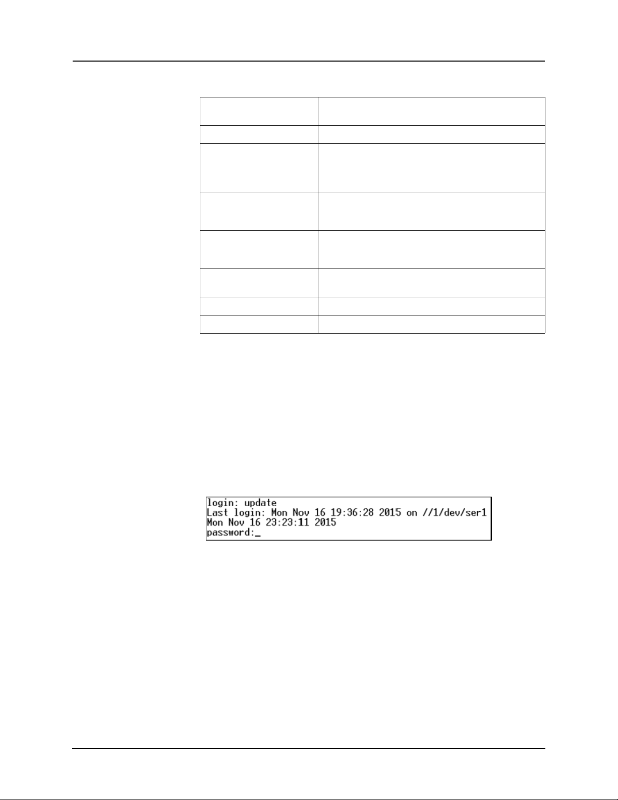
The relay has an update login that can be accessed by a connection through a
VT100 terminal emulator (such as HyperTerminal). This login is available
only from Port 1.
1 Use the terminal program to connect to Port 1.
2 Select Ent
3 Login as update in
er, the terminal responds with a login prompt.
lower case.
4 Relay responds with "password" prompt.
Figure 2.8: Firmware Update password prompt
5 Enter password.
The firmware update is used to update
the relay’s software with maintenance
or enhancement releases. Please see the B-PRO Firmware Update Procedure
documentation that comes with the firmware update for instructions on how to
update the firmware.
D02416R04.00 F-PRO 5100 User Manual 2-13
Page 28

Page 29
3 Using the IED (Getting Started)
F-PRO Feeder Protection Relay
Offline Mode - Settings Software
Online Mode - Terminal Mode
F-PRO
Feeder Protection
Model 5100
Port 1
Date &
Time
View
Readings
View
Logs
Prev
Next
Targ et
Clear
Targ et
1999 JUN 07
Relay Functional
IRIG-B Functional
Service Required
Test Mode
Alarm
Start-up Sequence
The following initialization sequence takes place:
Test Mode—red LED on 2 seconds after power applied
Relay Functional—green LED on 5 seconds after power applied
Front Display—on 30 seconds after power applied
Test Mode—red LED off 40 seconds after power applied
When the relay is powered up, the normal sequenc
e of LED operation is Test
Mode followed by Relay Functional and IRIG-B Functional (if available), display on, then Test Mode off. The
entire sequence takes about 40 seconds.
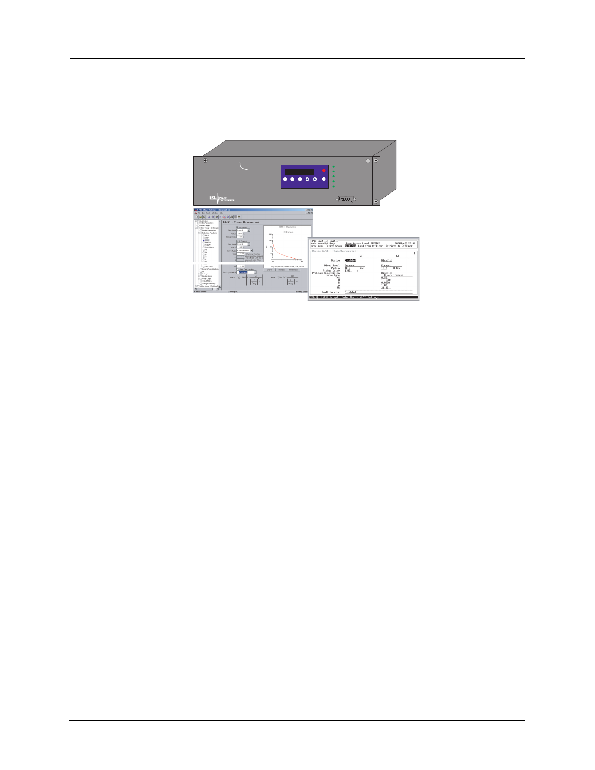
Ways to interface with F-PRO:
• Front panel display
• Terminal Mode
• Offliner Settings software
D02416R04.00 F-PRO 5100 User Manual 3-1
Page 30
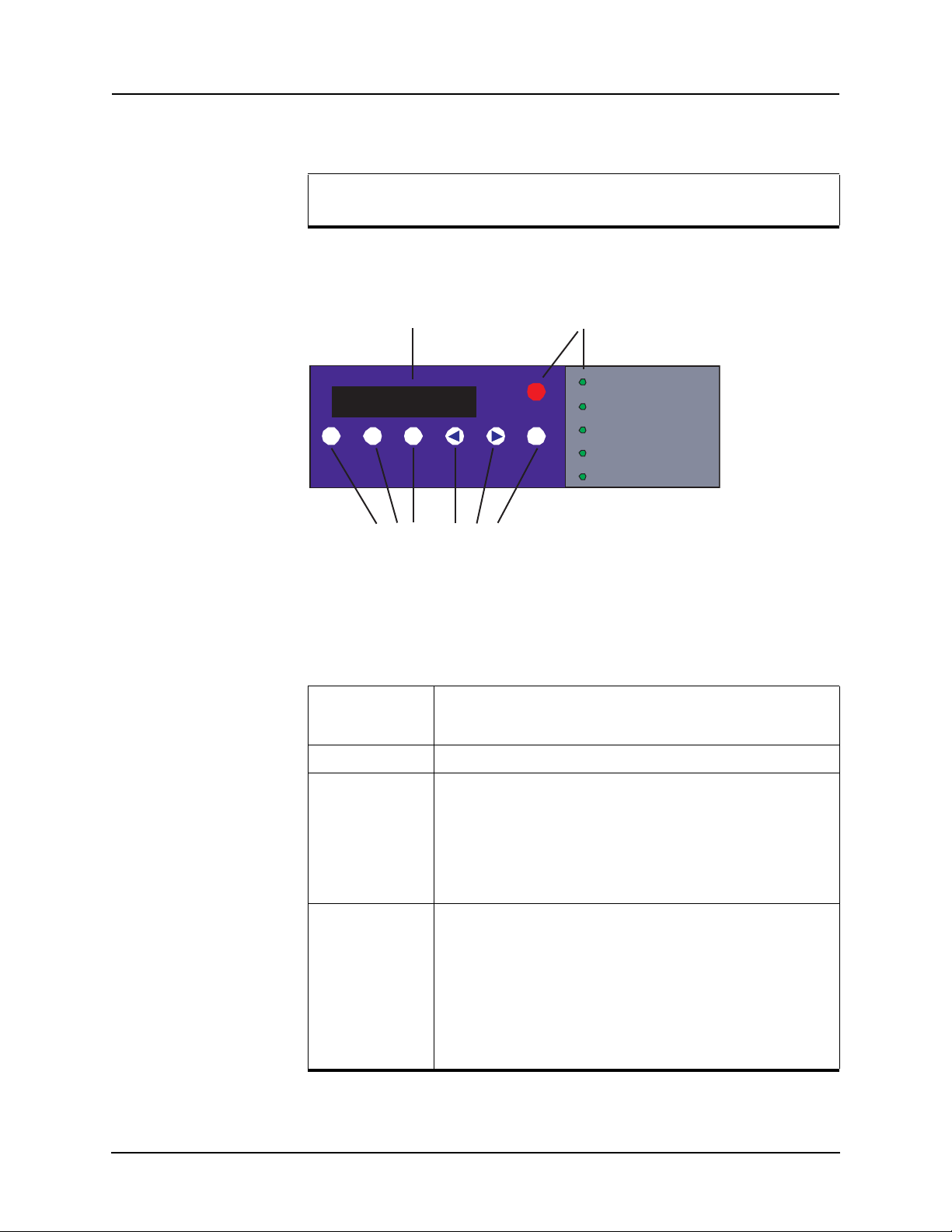
3 Using the IED (Getting Started)
Date &
Time
View
Readings
View
Logs
Previous Next
Target
Clear
Target
Pri V 0.0 kV ph - ph
I 0.0 A line
Display LED Lights
Push Buttons
Relay Functional
IRIG-B Functional
Service Required
Test Mode
Alarm
Front Panel Display
View or change settings using Terminal Mode or loading a setting file
from Offliner Setting.
LED Lights
The front panel display is the fastest a
nd easiest way of getting information
from the relay.
Figure 3.1: Front Panel Display
The line display, the six LED lights and the six push buttons provide selective
information about the relay.
Relay
Functional
Indicates when the relay is functional. When the Relay Functional
gre
en LED goes on, the rear Relay Inoperative contact changes to an
open and the protective functions become functional.
IRIG-B Functional Indicates the presence of a valid IRIG-B time signal.
Service Required Indicates the relay needs service. This LED can be the same state as
Test Mod e Occurs when the relay output contact
3-2 F-PRO 5100 User Manual D02416R04.00
Relay Functional LED or can be of the opposite state depending on
the
the nature of the problem.
The following items bring up this LED:
• DSP failure - protection difficulties within the relay.
• Communication failure within the relay.
• Internal relay problems.
s are intentionally blocked.
Possible reasons are:
• Relay initialization on start-up
• User interface processor has reset and is being tested.
You cannot communicate with the relay through the ports until the front
display becomes a
the red Target LED remains off after this start-up unless the relay had
unviewed target messages.
Output contacts are controlled from the Util
ctive and the Test Mode LED goes out. Normally,
ities menu.
Page 31

3 Using the IED (Getting Started)
Push Buttons
ALARM Occurs when an enabled relay function picks up.
Target Indicates that a fault has taken place.
Date &Time Pressing the Date &Time button displays the date and time stored on
View Readings Pressing the View Readings button obtains metering information about
View Logs Pressing the View Logs button displays the target information if a relay
Previous/Next Scroll through the menu by pressing Previous and Next.
Clear Target When a fault takes place, the red target light appears. You can select a
The red Alarm LED should be off if there are no inputs to the relay. If
the Alarm LED is on, check the e
play by pressing the V
An event message with date and time is presented in the display.
the relay. If the time is incorrect, connect to a PC in Terminal Mode and
go to Utilities>Setup>Time to make the change or connect to the IRIGB plug at the back of the relay. The front display time and date is automatically updated.
The green IRIG-B Functional LED comes on. The relay accepts either
modulated o
IRIG-B such as time skew for different time zones are available when
you establish communication with the PC.
the feed
oper
setting
Clear Target button to view all target information. If many faults have
been stored, you may need to push this button several times. Clearing
the target light does not clear the target information from the relay log.
The relay holds all target messages during a pow
and restart. Pressing the Clear Target push button displays any targets
not previously viewed on the front display and clears the Target LED
after the last target has been viewed.
Peak Demand Reset
Energy Reset
r unmodulated IRIG-B signals automatically. Options using
er, for details see “Display” on page 3-4.
ation has occurred, for details see “Display” on page 3-4.
option to reset the target light after a short time delay. Use the
iew Logs button.
vent log messages on the front dis-
er supply shutdown
D02416R04.00 F-PRO 5100 User Manual 3-3
Page 32
3 Using the IED (Getting Started)
Date &
Time
View
Readings
View
Logs
Previous Next
Target
Clear
Target
2000 JUL 07 13:22:07
View Readings
View Logs
Pri V 0.0 KV ph–ph
I 0.0 A line
2000Jun28 19:34:31.331
50LS-1 Main ABC: Trip
Display
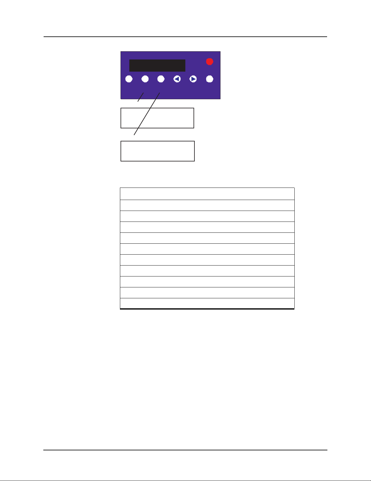
Figure 3.2: Line Display Examples
Line Display Messages
PRI V, I, P, Q
Va, Ia magnitude and angle
Vb, Ib magnitude and angle
Vc, Ic magnitude and angle
3IO magnitude and angle
Frequency and THD
Power Factor
Fault location, trip date and time of all functions involved.
Peak Demand
Energy In and Out
3-4 F-PRO 5100 User Manual D02416R04.00
Page 33
Terminal Mode
3 Using the IED (Getting Started)
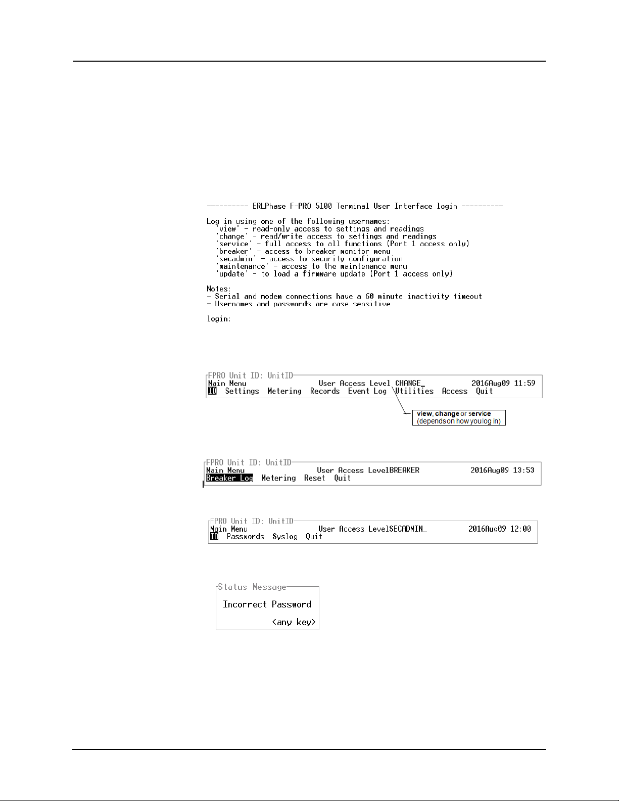
1 Establish terminal mode connection, for details see “Using HyperTerminal
to Access the Relay’s User Interface” on page 2-5.
2 Login as one of v
iew, breaker, change, service, breaker, or secadmin.
(lower case). These five login names provide different levels of permission.
3 When connection is established and the
terminal mode program appears on
your screen, the following prompt should appear. If it doesn’t appear, press
Enter.
4 If login is successful, the Main Menu appears as follows:
- for vie
w, change or service login
- for breaker login
- for secadmin login
5 If login is unsuccessful, the Status Message will appear as follows:
Unit allows 7 unsuccessful login attempts before locking out the Access Level
for 5 minutes. Any attempts to login into locked out Access Level will fail. Access lockout and lockout period are Access Le
vel specific, i.e. if an Access
Level is locked out, the other Access Levels remain unaffected.
D02416R04.00 F-PRO 5100 User Manual 3-5
Page 34
3 Using the IED (Getting Started)
If the box around the menu does not appear as above, change the
font in your terminal program to one that supports line draw characters, e.g. terminal fonts.
If there are incorrect characters in the display, improper line feeds or
rased portions, the baud rate is too high for the quality of the com-
une
munication link. Use the Util
ities>Setup>Ports menu to reduce the re-
lay’s baud rate. The new rate is in effect at the next connection.
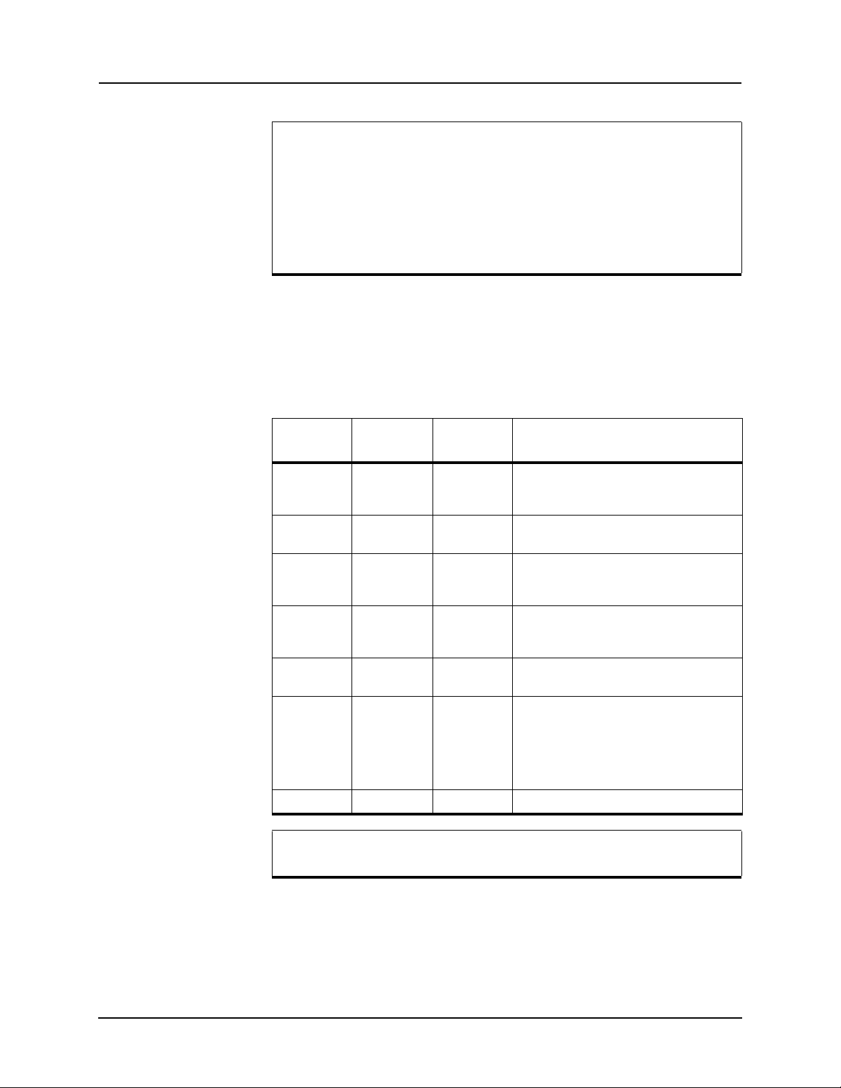
The relay supports four user access levels that control what relay functions are
available to you. The current access level is always shown in the centre of the
Main Menu heading.
To change the Access Level either login again using the desired access level as
yo
ur login name. To change between view, breaker, change and service Ac-
cess Level you can also use the Main Menu>Acce
ss menu.
Access
level
view view lowest
change change middle
service service highest
breaker breaker middle
secadmin secadmin security
maintenance maintenance maintenance
update update update Firmware update
Login name
Level/
function
Authorized functions
View settings, on-line readings and logs and
to list and u
cannot affect the operation of the controller.
Do all of the above, plus change the settings and delete records.
Do all of the above 2 categories, plus calibrate the analog inputs, manually control
output auxiliar
View breaker log and breaker metering.
Reset the breaker logic count and I2t values.
Change passwords.
View/change Syslog configuration.
Configure IP address, subnet mask, default
gatew
Restore default configuration/settings/calibration.
Enable/disable modem.
View/retrieve system diagnostics.
pload records. At this level you
y relays.
ay IP address.
Service access is only available through a local, front port connection
(Port 1).
Login Passwords
Individual passwords for all Access Levels are available to prevent or limit access to the IED. Passwords are mandatory. Units arrive
from the factory with
default passwords installed. Default passwords are as follows:
3-6 F-PRO 5100 User Manual D02416R04.00
Page 35
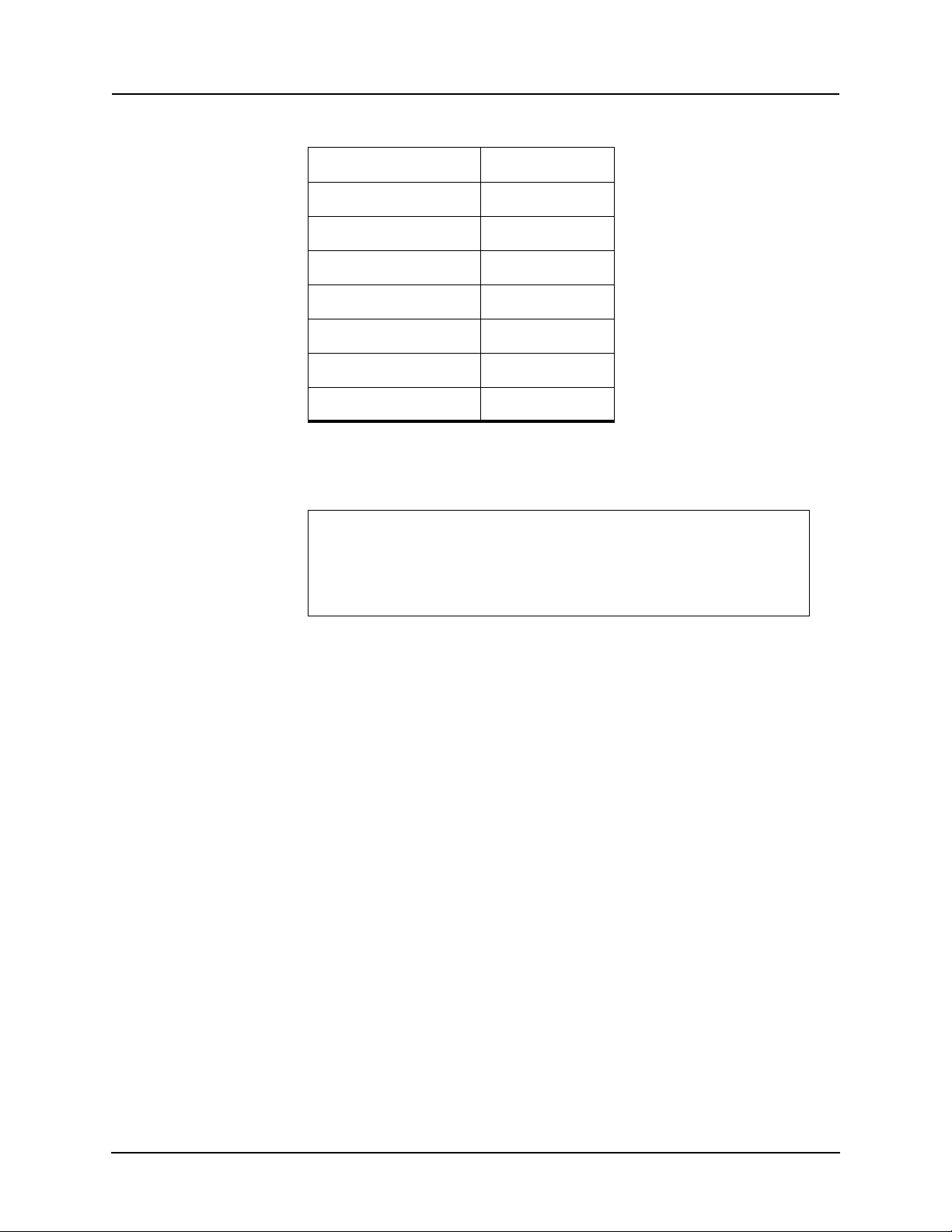
Access Level/Login name Default password
3 Using the IED (Getting Started)
view
change
service
breaker
secadmin
maintenance
update
view
change
service
breaker
secadmin
maintenance
update
You can only change the passwords from the service level through the Access
menu minimizing the chance that a password is changed casually and provides
a means of resolving situations where a password has been forgotten.
The following rules are applied, when firmware is upgraded to a version with secadmin
login for the first time
• the current password is preserved, if A
• a default password is assigned to an Access Level, if Access Level doe
password assigned to/associated with it.
ccess Level has a password assigned to it;
s not have a
D02416R04.00 F-PRO 5100 User Manual 3-7
Page 36
3 Using the IED (Getting Started)
Terminal Mode Menus
Use the right and left arrow keys and the enter key to move around in the terminal mode screen. The mouse does not work in VT100 terminal mode. Items
from the menu a
tivating it using the <Enter> key. As a short-cut
re selected by moving the highlight to the desired item and ac-
, use the first letter of the menu
item to access it directly.
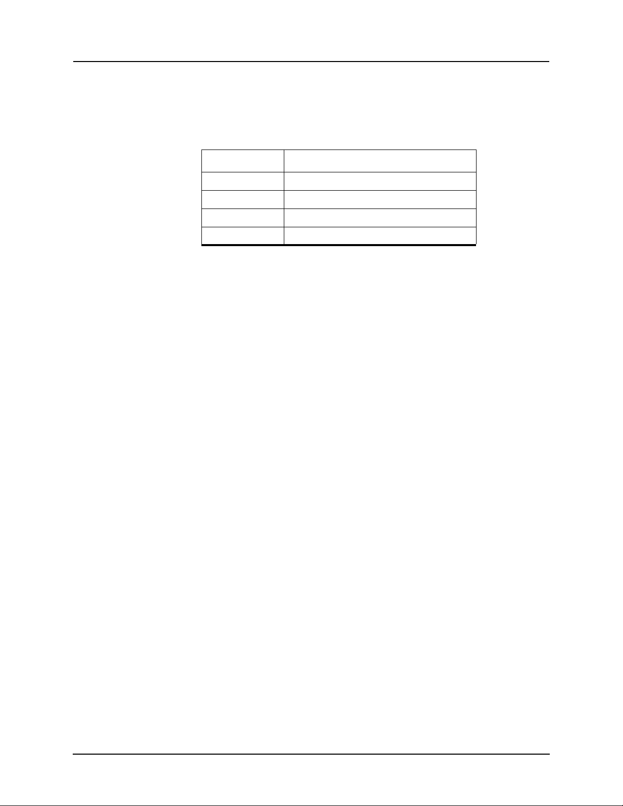
Key Function
<F2> Accept or Freeze or Execute
<F3> Quit or Exit
<F4> Copy Group
<Esc> Back to previous menu level
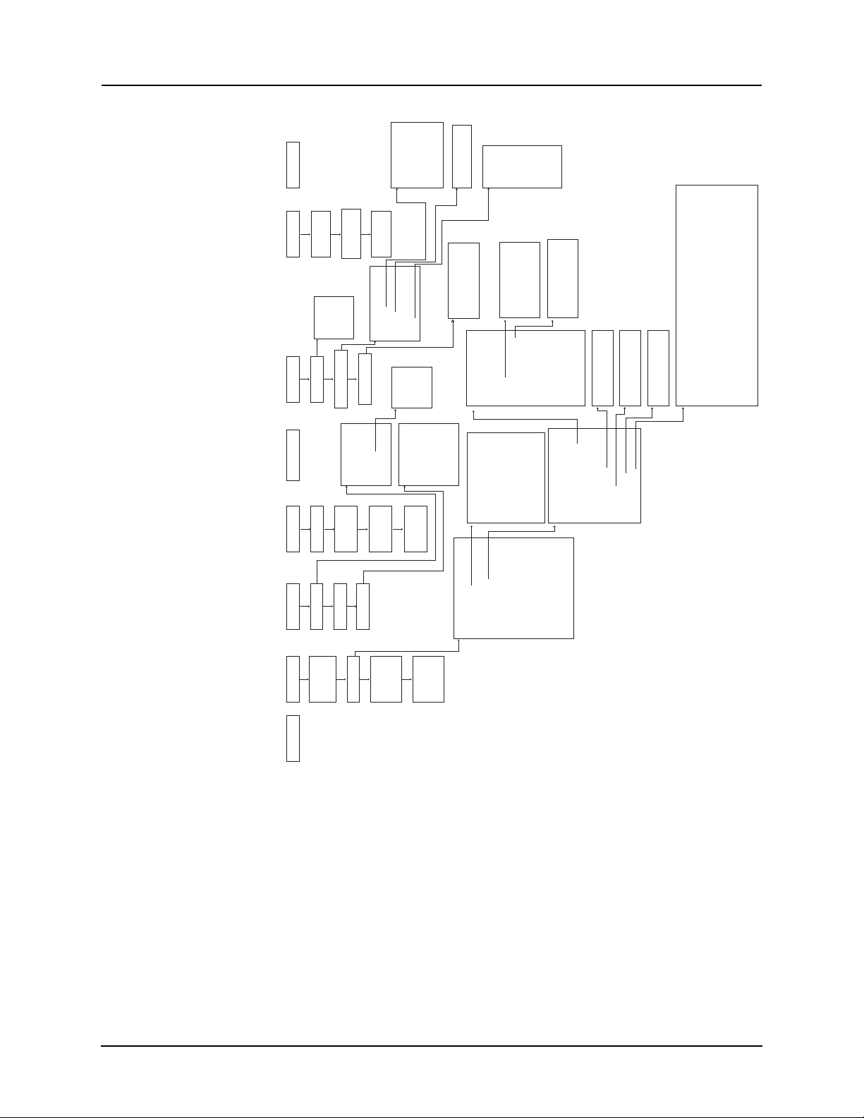
The menu tree consists of a series of sub-menus, for details see Figure 3.3:
Terminal Mode Menus for view, change and service login on page 3-9.
The Enter key allows you to toggle through a
abled. The Enter key toggles forward through the
list of selections, i.e. enabled/dis-
list, while the space bar
moves backward through the list. In this manner you do not have to scroll
through the entire list to get back to a previous selection, you can use the space
bar.
For certain lists a pick box appears when there is a long list of selections to
e from, for example, ProLogic inputs. You can scroll though these boxes
chos
with the arrow keys or the Enter key. Use the F2 key to make a selection or F3
to leave.
3-8 F-PRO 5100 User Manual D02416R04.00
Page 37
Calibrate
Main VA, VB, VC
Main IA, IB, IC,
Output Contacts
Aux IA, IB, IC.
Sync V
Toggle 1-12
Erase
Records
Event Log
Trends
Demand
Peak
Energy
Breaker
3 Using the IED (Getting Started)
VIEW
Access
Setup
Time
Setup
Event Log
List
Records
Analog
MeteringId QuitAccessUtilities
Access
CHANGE
BREAKER
Ports
SCADA
Maintenance
Diagnostics
Maintenance
Analog
Analog Inputs
Line Quantities
Demand
Fault
Trend
Recording
I/O
Logic
Access
d
Calibrate
Outputs
Control Virtual Inputs
Erase
Demand
Demand
Logic
Protection
I*I*t
Event
Recording
Energy
Peak
ProLogic
Setting Groups
Virtual Inputs
Recording
Diagnostics
Breaker Logic
F-PRO Settings
50/51
Transfer Diagnostics
Modbus
Protection Functions
50LS
50BF
50/51..
Identification
Relay
Comment
Analog Input Names
Identification..
F-PRO System Parameters
Setting Group 1
Setting Group 2
Setting Group 3
50/51
50N/51N
46-50/46-51
Sync Check & 79
25/27/59 Sync Check
79
Sync Check & 79..
5927608132
External Input Names
Output Contact Names
Setting Group 4
Setting Group 5
21P
Setting Group Names
Virtual Input Names
Setting Groups 1 – 8
Feeder Parameters
Setting Group 6
Setting Group 7
Setting Group 8
Recording
THD Alarm
Breaker Logic
Breaker Logic 1 – 10
ProLogic
ProLogic 1 – 10
Protection Functions..
Demand/Trend Metering
I*I*t
Breaker Logic..
ProLogic..
Group Logic..
Output Matrix..
Output Matrix #1 (50LS, 50BF, 25/27/59 Sync Check, 79)
Output Matrix #2 50/51, 50N/51N, 46-50/46-51)
Output Matrix #3 (32, 27, 59, 60, 81, THD, Aux Fail)
Output Matrix #4 (External Inputs)
Output Matrix #5 (ProLogic)
Output Matrix #6 (BkrLogic)
Output Matrix #7 (Virtual Inputs 1–15)
Group Logic
Group Logic 1 – 16
Output Matrix #8 (Virtual Inputs 16–30)
Settings
Active
Group
Load
Settings
from
Offliner
to
Offliner
Retrieve
Figure 3.3: Terminal Mode Menus for view, change and service login
D02416R04.00 F-PRO 5100 User Manual 3-9
Page 38
3 Using the IED (Getting Started)
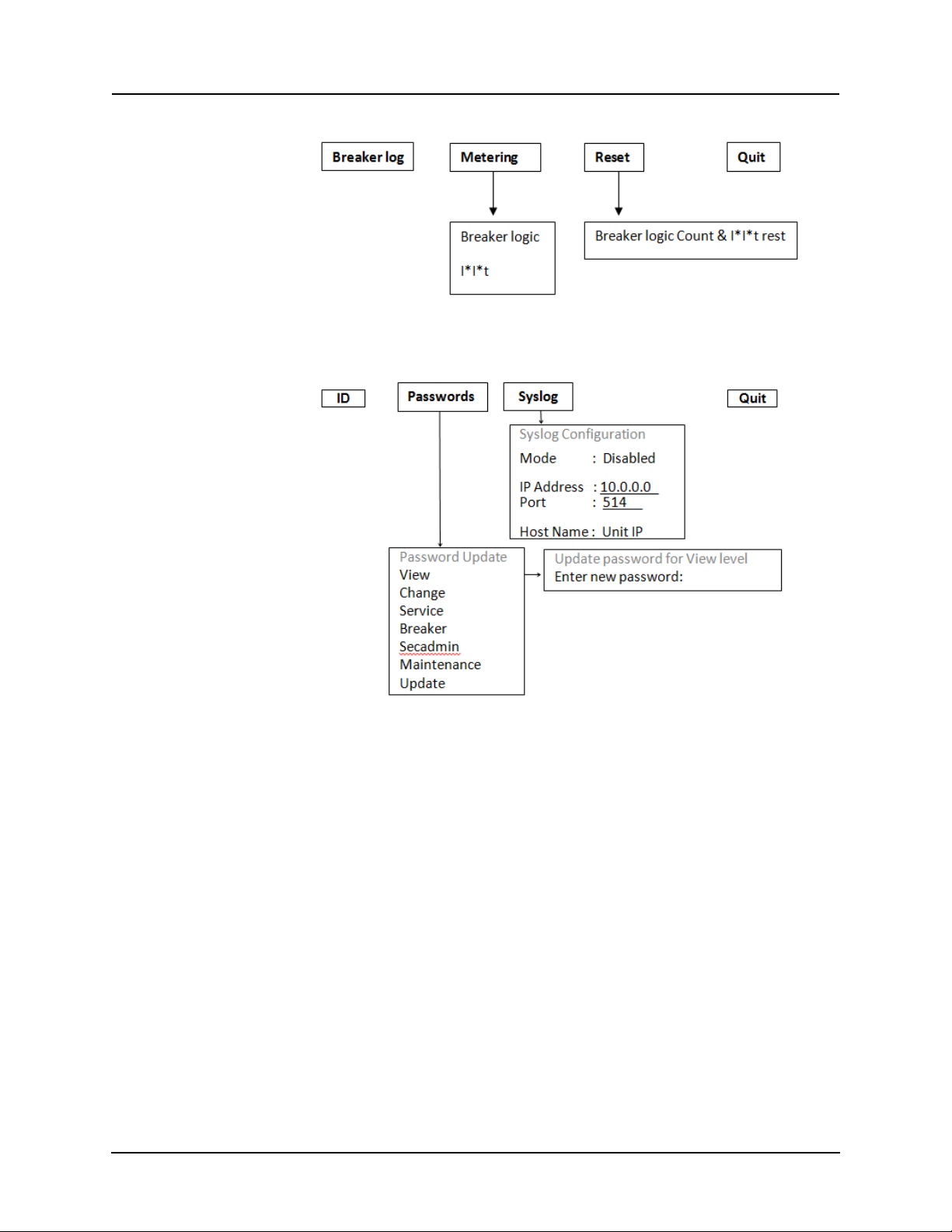
Figure 3.4: Terminal Mode Menu for Breaker login
Figure 3.5: Terminal Mode Menus for secadmin login
3-10 F-PRO 5100 User Manual D02416R04.00
Page 39

3 Using the IED (Getting Started)
ID Settings Metering Records Event Log Utilities Access Quit
View, Change or Service Login
The Main Menu display for view, change or service login is:
ID Provides the device serial number, software version, required settings version,
nominal system values and external input board rating. There are no user settings here.
Settings Submenus: Active Group, Settings, Load from Offl
Allows input of all the setting informat
menus to change relay setti
ngs related to protection functions, when settings
ion for the relay. Includes all the sub-
are changed they are not saved until you confirm the changes—Save and Load
Setting Changes Now? [y/n].
Settings
Includes all the submenus to create a relay settings pertaining to protection
functions. When these settings are made or changed, you can load them into
the relay. Allows input of all settings information.
Settings submenus: Identification, F-PRO System Parameters, Setting Group 1
to 8, Recording.
Identification..
Relay Serial Number, Software Version, Relay ID, Line Name, Station
Name, Station Number and Location.
Comments Enter any appropriate comment.
Analog Input Names Name inputs, Main VA, VB, VC, Main IA, IB, IC, Aux IA, IB, IC, Sync
External Inputs
Names
V.
Name external inputs 1 to 9.
iner, Retrieve to Offliner
Output Contact
Names
Setting Group Names Name setting groups 1 to 8
Virtual Input Names Name virtual inputs 1 to 30
Name auxiliary relay output contacts 1 to 12.
The following characters are not allowed in the above setting parameters: “ ”,
“\”, “/”, “:”, “*”, “?”, “|”, “"“, “<“, and “>”.
Load From Offliner
You can download the settings file into the relay using the terminal mode
menu.
1 On the Window’s desktop, double-click F-PRO Of
initial Offliner Settings screen appears.
2 Enter the required settings.
3 Save the settings to a file on your PC.
D02416R04.00 F-PRO 5100 User Manual 3-11
fliner Settings icon. The
Page 40
3 Using the IED (Getting Started)
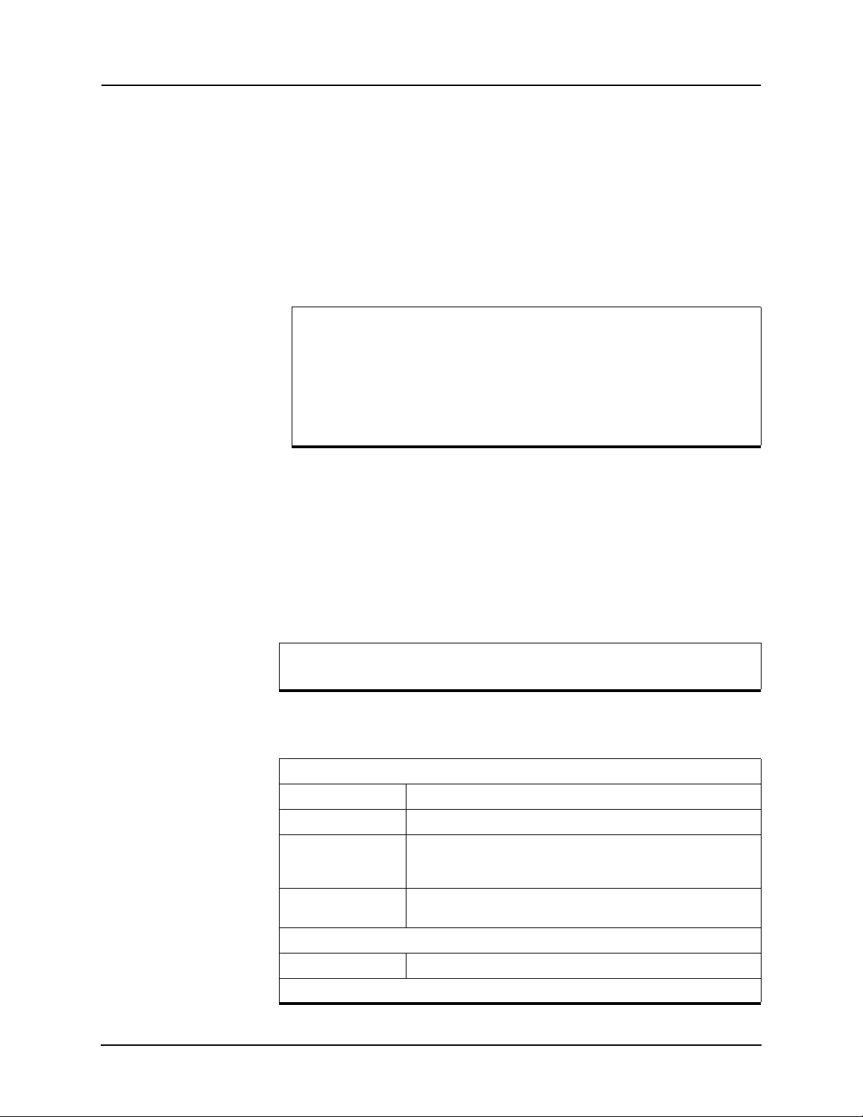
4 Start the Terminal Mode of F-PRO, login as change or service, then access
the Settings menu and activate Load from Offliner function.
5 Reply Yes to
6 In your terminal program, initiate transfer of
the “Ready to load remote setting.” prompt.
the setting file created in step
2 above. (For example, with Window’s HyperTerminal, you would select
Transfer, then Send File. Browse to find the file, then select Open and finally, Se
7 When the file has been transferred,
nd.
verified and loaded, a message “New
settings loaded and secure” is displayed.
A “serial number discrepancy” message may appear. This is to ensure that you are aware of the exact relay to which the settings are
being loade
d. If this happens, check the relay serial number using
the terminal mode ID menu item. Type this serial number into the
F-PRO Serial No. box in the Identification tab display area of Offlin-
tings. Alternately you may check the Ignore Serial Number
er Set
check box to bypass serial number supervision.
Retrieve To Offliner
To transfer the relay’s current settings to the PC do the following:
1 Navigate to Se
2 Select Ent
ttings>Retrieve To Offliner.
er.
3 The relay asks you if you wish to continue. Select Y for yes.
4 The file is sent to the directory d
efined by the HyperTerminal menu Trans-
fer>Receive File.
When using HyperTerminal use Z-modem (no crash recovery), files
are
received and auto incremented.
Metering Submenus: Analog, I/O, Logic, for more details about
metering see “Metering
Data” on page 3-17.
Analog
Analog Inputs Provides secondary values of the ac analog voltages and currents.
Line Quantities Provides primary voltage kV phase to phase of each line.
Demand Demand
I*I*t Displays the accumulated I*I*t value and I*I*t value for the last oper-
I/O
Logic
3-12 F-PRO 5100 User Manual D02416R04.00
Energy
Peak
ation.
Displays the state of the external inputs and the output contacts.
Page 41
Protection Protection Functions.
3 Using the IED (Getting Started)
ProLogic Provides the present status of the internal logic states. When a logic
level becomes active, it
Setting Group Displays current active Setting Group and Group Logic.
Virtual Inputs Provides the present status of the virtual in
logic level becomes active, its state changes from low to high.
s state changes from low to high.
put logic states. When a
Records Submenus - List, Fault Recording, Trend Recording and Event Recording.
Contains the means for initiating
List Lists all records.
Fault Recording Creates fault records.
Trend Recording Creates trend records.
Event Recording Creates event records.
Retrieve Records from the Relay
and examining recordings.
To retrieve records from the relay do the following:
1 Navigate to Records>List and
2 Select Records using the s
press Enter; a records list appears.
pace bar and select R. (You can also press Enter
to retrieve a record directly.) The record will be saved in the directory specified by the terminal emulation program.
When using HyperTerminal if “Use receiving protocol:” is set to “Z
modem with Crash Reco
very”, file transfers are skipped by Hyper-
Terminal if the record already exists in the downloads folder.
When using HyperTerminal use Z-modem (no crash recovery), files
received and auto incremented.
are
Delete Records from the Relay
To delete records from the relay do the following:
1 Navigate to Records>List and
2 Select the records for deletion with the space bar and select D. The sele
records will be deleted.
Event Log The event log lists events stored
events logged is available, for details see “Event Messages” in Appendix D.
If an event triggered a record, then an (R) is displayed by the event.
press Enter.
cted
in the relay. A complete list of the types of
D02416R04.00 F-PRO 5100 User Manual 3-13
Page 42
3 Using the IED (Getting Started)
Utilities Sub-menus: Setup, Maintenance, Diagnostics.
Setup
Time - set manual time, IRIG-B skew control. Requires change or
service acce
ss level.
Maintenance
Diagnostics
Ports - change Baud rates on communication ports. Requires
change or
SCADA – select which SCADA protocol (Modbus or DNP3) to run
on the SC
such as address or timeout. Requires change or service access
level.
Calibrate – calibrate all 10 analog ac.
Outputs – close and open output contacts independent of the associated relay functions. Requires service access level.
Control Virtual Inputs – set, re-set and pulse
width is 1 second. Latched virtual inputs reset after pulse command
has executed. Requires change or access level.
Erase – use submenus Records and Event Log
records from the relay memory. Reset Demand Metering, I
Breaker Logic counts. Requires change or service access level.
Transfer Diagnostics – transfers relay d
diagnostic file can be sent to us for analysis.
service access level.
ADA port. Configure parameters for the selected protocol
Requires service access level.
virtual inputs. Pulse
s to erase these
iagnostic file to the PC. The
2
t and
Modbus – allows Modbus Communications to enter
Mode. Follow directions on the screen. Programming done using the
Modicon Modbus Protocol Reference Guide PI-MBUS-300 Rev. G
published by Modicon, Inc., dated November 1994. For details see
“Modbus RTU Communication Protocol” in Appendix E.
its Diagnostic
3-14 F-PRO 5100 User Manual D02416R04.00
Page 43

3 Using the IED (Getting Started)
Breaker Log Metering Reset Quit
Access Submenus: View Access, BREAKER Access, CHANGE Access.
view Changes the access level to view. Allows you read-only access to
relay information.
breaker Changes the access level to breaker.
change Changes the access level to change. Allows you to modify settings
and delete r
ecords.
Quit Selecting this option ends serial port communication with the relay.
Breaker Login
The Main Menu display for the breaker login is:
The Main Menu display for breaker login is:
Breaker Log The breaker log provides a log of breaker monitoring events.
Metering The metering quantities provided are breaker logic and I*I*t. F
tion of those quantities see “Breaker Logic” on page 4-15 and “I*I*t” on
page 4-16.
Reset Use Reset to preset/reset the brea
Passwords
Password update
ker logic count and the I*I*t.
Password Update includes the submenus for all Access Levels passwords updates.
or an explana-
View
Change
Service
Breaker
Secadmin
Maintenance
Update
Password update for view login
Password update for ch
Password update for service login
Password update for b
PAssword update for secad
Password update for m
Password update for up
ange login
reaker login
min login
aintenance login
date login
D02416R04.00 F-PRO 5100 User Manual 3-15
Page 44
Syslog Syslog Configuration
Syslog Configuration submenu allows configuration of Syslog server communication parameters as well as
Syslog message (see section 8 “Cyber Security”).
selection of “Host Name” field value in the unit
Modes of Syslog server operation are defi
Mode Description
Disabled
UDP
Communication with Syslog server is disabled
UDP protocol is used for communication w
ned in the table below:
ith Syslog server
“IP Address” parameter defines Syslog server IP Address.
“Port” parameter defines Syslog server IP port for
receiving Syslog messages.
“Host Name” parameter values are as follows
Host Name Description
Unit IP Address
Unit Serial Number
Unit ID
Unit IP Address is used for Syslog message "Host Name" field
Unit Serial Number is used for Syslog message "H
Unit ID is used for Syslog message "Host Name" field
ost Name" field
Quit Selecting this option ends serial port communication with the relay.
Page 45

Metering Data
3 Using the IED (Getting Started)
Front Panel Metering
The quantities provided on the front panel display include:
• Positive sequence L-L voltage
• Positive sequence line current
• Line MW, MVAR
• Positive sequence frequency
• THD
• Power Factor
• Primary line to neutral voltages and currents
• Primary 3IO current
• Peak MW In/Out, MVAR In/Out, Ia, Ib, Ic
• MWh In/Out
• MVARh In/Out
All quantities are in primary unless otherwise noted.
TUI Metering The TUI provides the following metering quantities.
Analog/Analog Inputs
Displays all secondary values (magnitude and angle) of the voltage and current
analog inputs.
Analog/Line Quantities
Displays the positive sequence L-L voltage, positive sequence line current, real
and reactive power, positive sequence voltage frequency, THD, power factor
and 3IO current. All values are in primary quantities. These are also available
from the front panel.
Analog/Demand/Demand
Displays the current values of the demand metering quantities. Includes MW
In/Out, MVAR In/Out, ABC phase voltages, ABC phase currents, frequency
and THD, as well as, time of last reset.
Analog/Demand/Energy
Displays the current value of accumulated MWh and MVARh, as well as, the
date of the last preset/reset.
Analog/Demand/Peak
Displays the peak value of the following quantities: MW In/Out, MVAR In/
Out, ABC phase feeder currents, as well as the time of occurence.
Analog/I*I*t
Displays the valus of I2t for the last breaker operation, the total accumulated
2
t, the last preset/reset I2t value and the accumulated I2t set limit for both the
I
main and auxiliary breakers.
D02416R04.00 F-PRO 5100 User Manual 3-17
Page 46

3 Using the IED (Getting Started)
I/O
Displays the status of all external inputs and output contacts.
Logic/Protection
Displays the status of all internal logic, including alarm and trip states of all the
relay elements.
Logic/ProLogic
Displays the status of all ProLogic.
Logic/Setting Groups
Displays the current active setting group as well as the current state of all the
group logics.
Logic/Virtual Inputs
Displays the current state of all virtual inputs.
Logic/Breaker Logic
Displays the state of all breaker logics as well as the operation count. Also displays the last time the count was preset/reset.
3-18 F-PRO 5100 User Manual D02416R04.00
Page 47

4 Protection Functions and Specifications
Protection and Recording Functions
This section describes the equations and algorithms that define the F-PRO protection functions. The inverse time overcurren
where their pickup level has been exceeded. Devices 27, 59, 50LS, 50BF, 81,
50, 50N, 46050, 32 and ProLogic have user-settable intentional delay. When
an alarm occurs, the front alarm LED turns on and an output contact closes, if
you have selected this option in the output matrix settings. The alarm indication resets when the function is allowed to reset.
t functions have an alarm output
50/51/67 Phase Overcurrent
Phase Overcurrent provides protection to the line. You can define forward, reverse or non-directional control on either 50 or 51 functions.
You can apply inverse and instantaneous ov
ercurrent protection on the line
currents with this function. If ac current inputs are applied to the relay from
ring bus breakers, this current is summated to represent the total line current
and is used with this overcurrent function. You can set directional control of
50/51. If voltage is lost, the element becomes non-directional.
The fault location allows
Device 51 provides three IEC inverse time curve t
the function to initiate a fault location if it operates.
ypes, three IEEE inverse
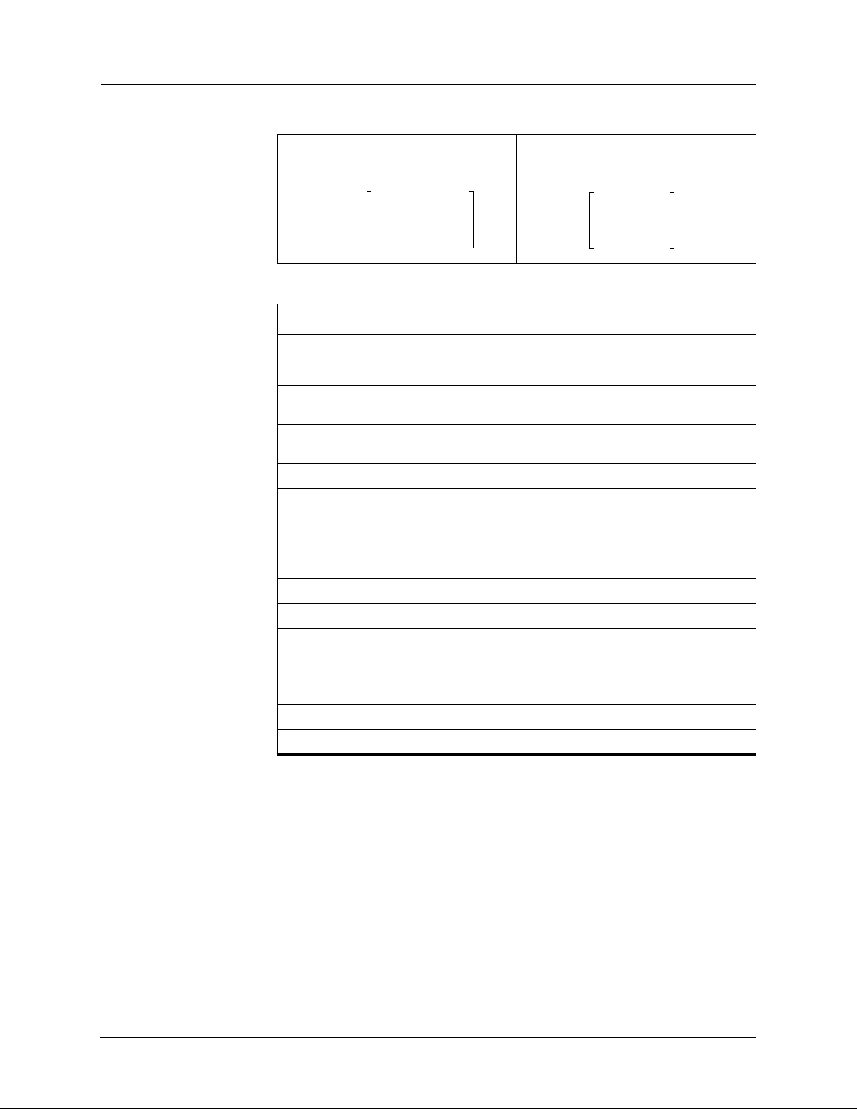
time curve types of overcurrent protection and one user-defined curve. The
equation and the parameters of Device 50/51/67 are listed below.
ProLogic control can be used to supervise
the inverse time integration of the
51.
Table 4.1: IEC and IEEE Curves
# Characteristic A B p TR
1
2
IEC Standard Inverse 0.14 0 0.02 13.50
IEC Very Inverse 13.5 0 1.0 47.30
3
4
5
6
7
IEC Extremely Inverse 80.0 0 2.0 80.00
IEEE Moderately Inverse 0.0103 0.0228 0.02 0.97
IEEE Very Inverse 3.922 0.0982 2.0 4.32
IEEE Extremely Inverse 5.64 0.0243 2.0 5.82
User-defined
0.001 to
100.0
0.0 to
10.0
0.01 to
10.0
0.1 to
00.0
1
* These constants are copied from the IEEE standards; they are not given in the
IEC standard.
D02416R04.00 F-PRO 5100 User Manual 4-1
Page 48
TI TMS B
A
I
Pickup
------------------
p
1–
-----------------------------------
+=
TI
TR
I
Pickup
------------------
2
1–
-----------------------------------
TMS
=
4 Protection Functions and Specifications
For I > pickup For I < pickup
50/51 Phase Overcurrent
50 Enable/disable
Directional Forward, reverse, non-directional
Pickup 0.25 to 50.00 (5 A)
Pickup Delay 0.01 to 99.99 seconds
0.05 to 10.00 (1 A)
0.00 to 99.99 (non-directional)
51 Enable/disable
Directional Forward, reverse, non-directional
Pickup 0.25 to 50.00 (5 A)
Curve Type For details see “IEC and IEEE Curves” on page 4-1
TMS 0.01 to 10.00
A 0.0010 to 1000.0000
B 0.0000 to 10.0000
p 0.01 to 10.00
TR 0.10 to 100.00
Initiate Fault Location Enable/disable
ProLogic Control Enable/disable
0.05 to 10.00 (1 A)
4-2 F-PRO 5100 User Manual D02416R04.00
Page 49
4 Protection Functions and Specifications
T 3 I0TMS A
B
3I 0
IPickup
--------------------
p
1–
--------------------------------------
+=
T 3 I0TMS
TR
3IO
IPickup
--------------------
2
1–
--------------------------------------
=
50N/51N/67 Neutral Overcurrent
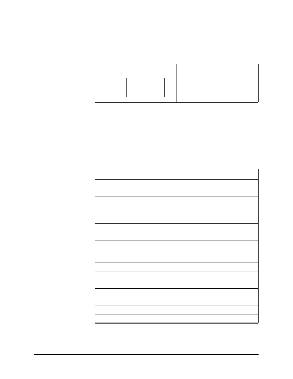
Neutral overcurrent provides protection for line-to-ground faults. You can define forward, reverse or non-directional control on either 50N or 51N functions. All the curve definitions are the
same as the phase overcurrent except
that this function uses 3I0 rather than phase current. The equation is:
For 3I0 > pickup For 3I0 < pickup
The Curve Type selection allows you to use a number of curves available in
this menu. All of these curve types are generated by the equation shown at the
bottom of the screen. If you choose a user-selectable curve, it can be created
using the parameters A, B and p.
The characteristic of the overcurrent function ca
n be rescaled by clicking on
the characteristics using the right mouse key and by making a box around the
area of interest. The characteristic can be printed by pressing the Print Graph
option.
50N/51N Neutral Overcurrent
50N Enable/disable
Directional Forward, reverse, non-directional
Pickup 0.25 to 50.00 (5 A)
Pickup Delay 0.01 to 99.99 seconds
51N Enable/disable
Directional Forward, reverse, non-directional
Pickup 0.25 to 50.00 (5 A)
Curve Type For details see “IEC and IEEE Curves” on page 4-1
TMS 0.01 to 10.00
A 0.0010 to 1000.0000
B 0.0000 to 10.0000
p 0.01 to 10.00
TR 0.10 to 100.00
Initiate Fault Location Enable/disable
ProLogic Control Enable/disable
0.05 to 10.00 (1 A)
0.00 to 99.99 (non-directional)
0.05 to 10.00 (1 A)
46/50/51/67 Negative Sequence Overcurrent
D02416R04.00 F-PRO 5100 User Manual 4-3
Negative Sequence Overcurrent provides protection for any unbalanced faults.
nctions 46-50/46-51/67 are similar to 50N/51N/67 except they use negative
Fu
Page 50
4 Protection Functions and Specifications
TI2 TMS B
A
I2
Pickup
------------------
p
1–
-----------------------------------
+=
TI2 TMS
TR
I2
Pickup
------------------
2
1–
-----------------------------------
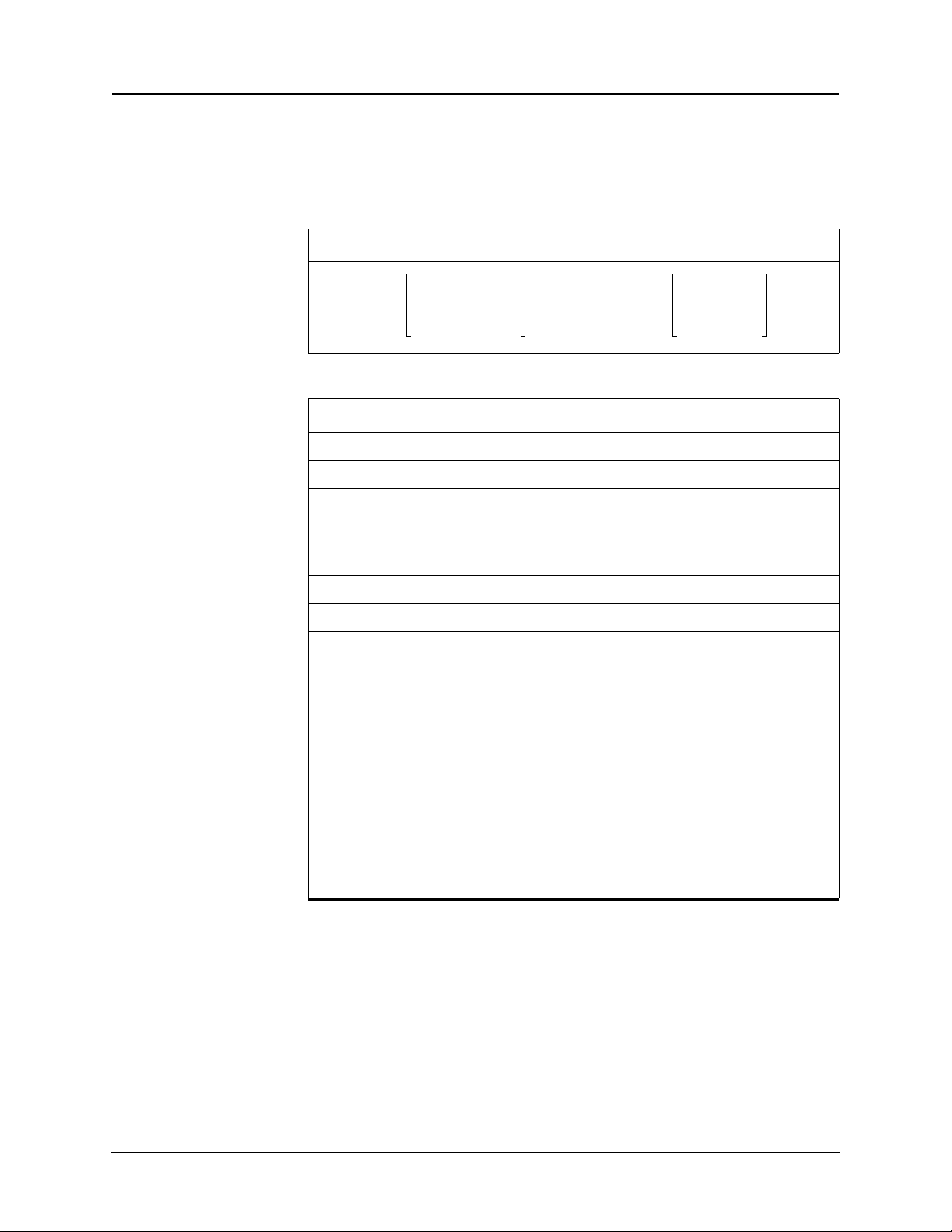
=
sequence current to drive their algorithms. You can define forward, reverse or
non-directional control on either 46-50 or 46-51 functions. All the curve definitions are the same as the P
function uses the negative sequence current (I2) rather than phase current. The
equation is:
For I
46-50/46-51N Negative Sequence Overcurrent
46-50 Enable/disable
Directional Forward, reverse, non-directional
Pickup 0.25 to 50.0 (5 A)
hase Overcurrent. The only difference is that this
> pickup For I2 < pickup
2
0.05 to 10.0 (1 A)
Pickup Delay 0.01 to 99.99 seconds
46-51 Enable/disable
Directional Forward, reverse, non-directional
Pickup 0.25 to 50.0 (5 A)
Curve Type For details see “IEC and IEEE Curves” on page 4-1
TMS 0.01 to 10.00
A 0.0010 to 1000.0000
B 0.0000 to 10.0000
p 0.01 to 10.00
TR 0.10 to 100.00
Initiate Fault Location Enable/disable
ProLogic Control Enable/disable
0.00 to 99.99 (non-directional)
0.05 to 10.0 (1 A)
4-4 F-PRO 5100 User Manual D02416R04.00
Page 51
4 Protection Functions and Specifications
50LS Low Set Overcurrent
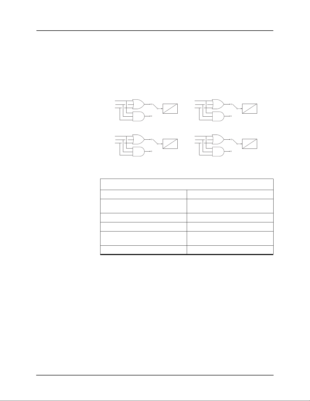
F-PRO provides 2 sets of definite time delay overcurrent protection functions
on each breaker: 50LS-1 Main, 50LS-2 Main, 50LS-1 Aux and 50LS-2 Aux.
You can set the logic gate to either an AND or an OR gate to detect all 3 phases
or any phase (of the 3 phases) overcurrent conditions. The definite time delay
can be set to 0.0 for a instantaneous trip.
Auxiliary definite time delay functions are available to monitor main and auxiliary CT currents.
50LS-1 Main
50 IMainA
50 IMainB
50 IMainC
50LS-1 Aux
50 IAuxA
50 IAuxB
50 IAuxC
101
105
100
104
T
T
Figure 4.1: 50LS Low Set Overcurrent
50 Low Set Overcurrent
50LS-2 Main
50 IMainA
50 IMainB
50 IMainC
O
50LS-2 Aux
50 IAuxA
50 IAuxB
50 IAuxC
O
102
103
106
107
T
O
T
O
50LS Main Enable/disable
Pickup 0.1 to 50.0 amps (5 A)
0.02 to 10.00 amps (1 A)
Pickup Delay 0.00 to 99.99 seconds
50LS Aux Enable/disable
Pickup 0.1 to 50.0 amps (5 A)
0.02 to 10.00 amps (1 A)
Pickup Delay 0.00 to 99.99 seconds
D02416R04.00 F-PRO 5100 User Manual 4-5
Page 52
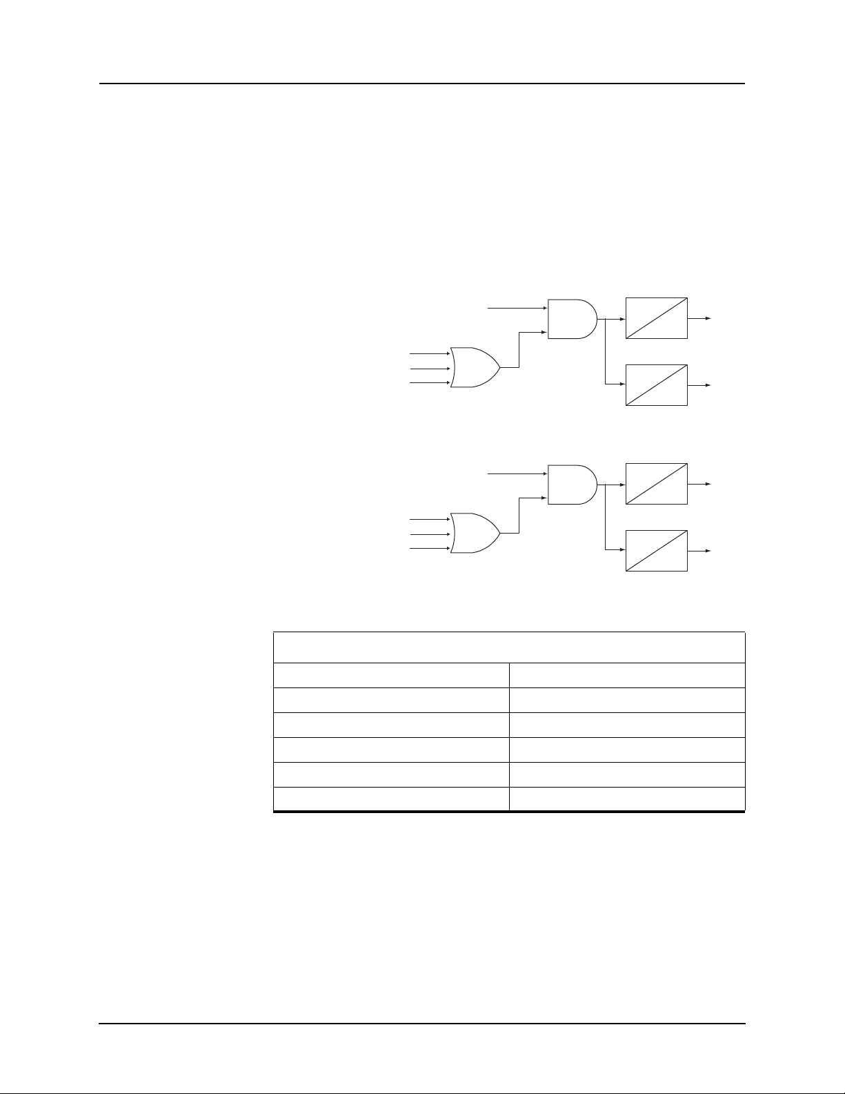
4 Protection Functions and Specifications
50 IMainA (fixed 0.2 amps)
50 IMainB (fixed 0.2 amps)
50 IMainC (fixed 0.2 amps)
T1
0
108
109
Breaker failure Initiator (from Output Matrix)
T2
0
Output1
Output2
50 IAuxA (fixed 0.2 amps)
50 IAuxB (fixed 0.2 amps)
50 IAuxC (fixed 0.2 amps)
T1
0
110
111
Breaker failure Initiator (from Output Matrix)
T2
0
Output1
Output2
50BF Breaker Failure
There are two sets of breaker failure pro
50BF Auxiliary – one for each breaker. When breaker failure is initiated by a
trip or other internal logic (user-settable through the output matrix) and the
breaker current still exists, two timers (T1 and T2 – user-settable) are started.
After these timers are timed out, and if the current still exists indicating a
breaker failure, the output of this function is set high. Use the two outputs of
this function to trip another trip coil or the next level of breakers, such as bus
breakers. The breaker failure protection logic diagram is shown below. Phase
current supervision is fixed at 4% of I nominal and is shown for a 5 A relay.
Figure 4.2: 50BF Main Breaker Failure
tection functions, 50BF Main and
Figure 4.3: 50BF Aux Breaker Failure
50BF Breaker Failure
Main Enable/disable
Pickup Delay 1 0.01 to 99.99 seconds
Pickup Delay 2 0.01 to 99.99 seconds
Auxiliary Enable/disable
Pickup Delay 1 0.01 to 99.99 seconds
Pickup Delay 2 0.01 to 99.99 seconds
4-6 F-PRO 5100 User Manual D02416R04.00
Page 53
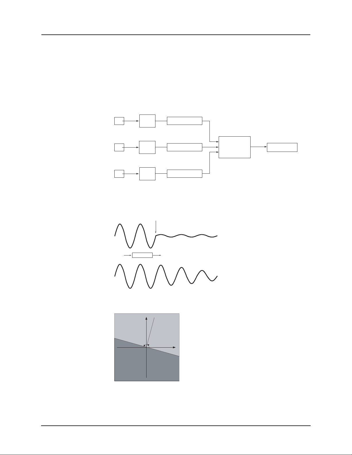
4 Protection Functions and Specifications
Z
posmem
V
posmem
I
pos
---------------------
=
R
jx
Forward
Reverse
90°
Line Z Angle
Line Impedance
Directional Element The directional element of F-PRO uses the memory-polarized, voltage-based
positive sequence impedance (Z
pos mem
) to determine the fault direction.
This impedance is defined as:
where V
is the memorized positive sequence voltage calculated from the
pos mem
polarization voltage signals, Figure 4.5: Effect of the Ring Filter on page 4-7,
and I
is the positive sequence line current.
pos
Va
Vb
Vc Vc_polarization
Figure 4.4: Vpos_mem Calculation
Ring
Filter
Ring
Filter
Ring
Filter
Va_polarization
Vb_polarization
Sequence
Component
Filter
Vpos_mem
The effect of the Ring Filter (implemented in software) is to retain voltage information even if the voltage is
severely depressed by a fault.
Fault
Voltage
Ring Filter
Memory Voltage
Figure 4.5: Effect of the Ring Filter
D02416R04.00 F-PRO 5100 User Manual 4-7
Figure 4.6: Directional Element
Page 54

4 Protection Functions and Specifications
The principle of the directional element is shown above. If Z
pos mem
falls into
the light gray area, Forward, it indicates a forward fault; and if it falls into the
dark gray, Reverse area, a reverse fault is declared.
This directional element is used for directional overcurrent protection. No user
settings are needed for this function.
Directional Control for Overcurrent Functions in F-PRO
The positive sequence memory voltage is also used to provide directional control to the overcurrent functions within the F-PRO relay. In this case, the positive sequence memory voltage and the positive sequence line current
difference angles are compared to determine the directionality. For example, if
the relay is set to directional mode, it allows the overcurrent function to operate
if fault currents are towards the line and directions within 90 degrees of the line
angle. For details see
Figure 4.6: Directional Element on page 4-7.
For the directional control used on the overcurrent relays, a 30 cycle memory
action is used on the positive sequence voltage. This memory action takes
place only if a fault causes the positive sequence memory voltage to be above
2 volts secondary within the relay. If the positive sequence memory voltage
goes below 2 volts, the directional control of the overcurrent reverts to a non
directional characteristic, allowing it to operate and trip. For system faults that
are not bolted three-phase faults that cause all phase-to-neutral voltages to go
to zero, directional control are maintained because the positive sequence volt
age does not go to zero.
-
25/27/59 Sync Check The relay can bring in voltages from both line and bus PTs. The Sync Check
function, if enabled, looks at the voltage steady state angle between the bus and
the line PT voltage. If this angle is within a plus/minus specified value, (+/- 1
to 50 degree magnitude range of setting available), the function enables a def
inite time delay pickup (user-selectable 0 to 99.99 seconds) after which time
an output is produced. The line sync reference voltage is taken from a bus and/
or a line source; F-PRO uses one single-phase-to-neutral voltage. Settings
within the relay allow the single-phase quantity to be offset from Phase A of
the line PT by 0 to 330 degrees in 30 degree increments. The Dead Main Live
Sync, Live Main De ad Sync and Dead Main Dead Sync l og ic functions can u se
fixed values of main and sync positive secondary voltages to determine the
sync check condition. The voltage is fixed at 20 volts secondary, voltages be
low 20 volts are declared a dead state and voltages above 20 volts are declared
a live state.
When enabled, this function checks that the voltage angle between the Main ac
volts PT and bus sync ac volts PT voltages are within a specified value. Use
this function to ensure that closing a line to a system results in acceptable pow
er flow. The function uses three voltages from the Main PT and a single voltage
from the Sync PT to make the angle measurement.
The dead main dead sync logic is based on fixed voltages less than 20 volt seconds. i.e. The line or bus is declared dead if its voltage is less than that value.
The Sync PT Phase is settable in System Parameters from 0 to 330 degrees in
steps of 30 degrees.
-
-
-
4-8 F-PRO 5100 User Manual D02416R04.00
Page 55
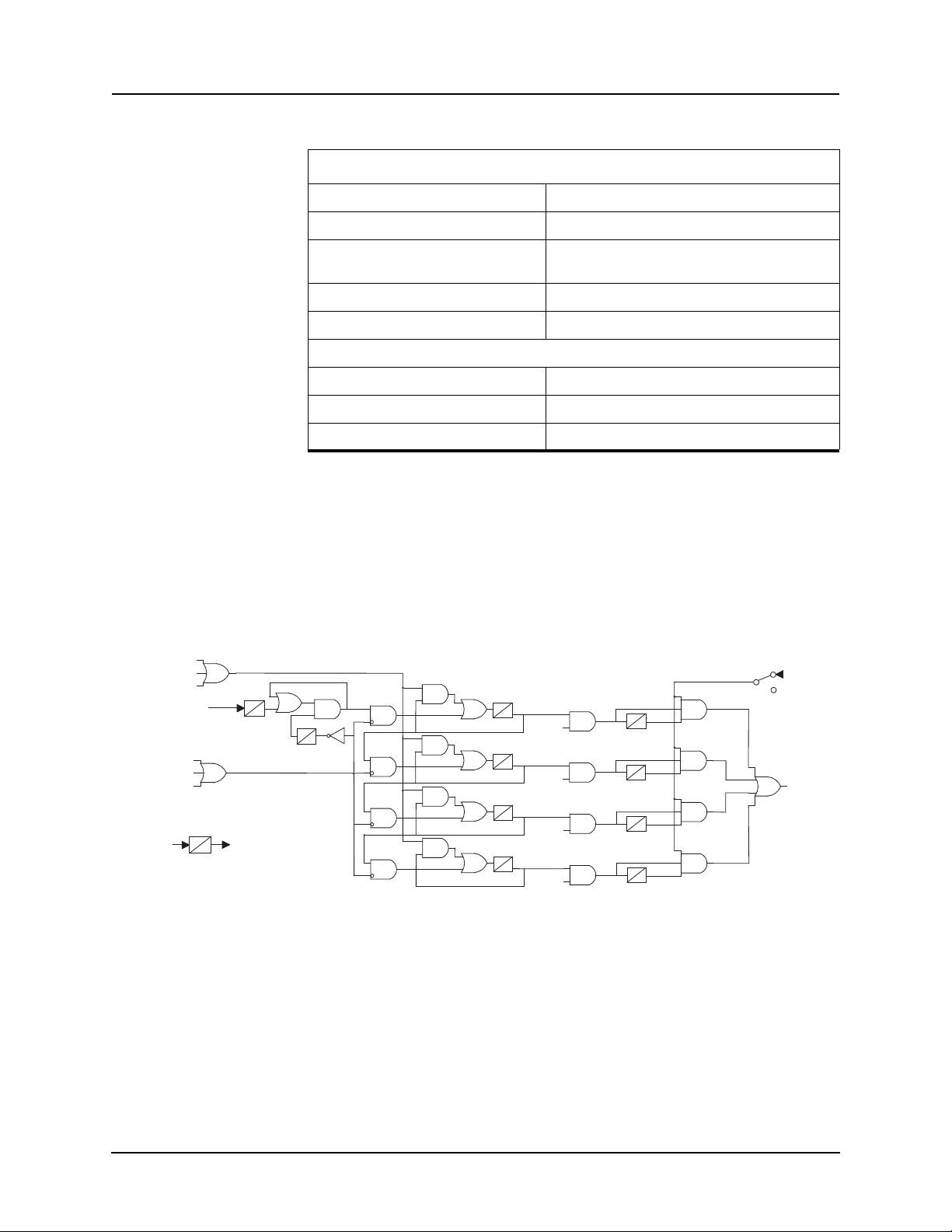
4 Protection Functions and Specifications
126
50 Ia main
50 Ib main
79 Block
(Output Matrix)
50 Ic main
(Low set 0.2A fi xed)
123
51 Alarm
51N Alarm
51/46 Alar m
146
Sync Control
(setting)
134
130
127
128
124
79 Initiator (output matrix)
125
0
TDI
Immediately Bl ock the Whole Functi on
All timer and Output are reset to 0, i.e.
Reset to the initial condition
+
T1
TD
0
TDB
Enable
0
TD
TP
0
142
135
131
T2
TD
Enabl e
TP
0
143
138
139
136
132
129
T3
TD
Enabl e
TP
0
144
140
137
133
130
T4
TD
Enable
TP
0
144
140
25/27/59 Sync Check
25 Sync Check Enable/disable
Maximum Voltage 60.0 to 138.0 volts secondary
79Main/79Aux Recloser
Minimum Voltage 40.0 Mi
nimum Voltage Maximum Voltage -0.1
115 volts secondary
Angle Difference 1.0 to 50.0 degrees
Pickup Delay 0.00 to 99.99 seconds
Main/Aux
Enable Dead Main Live Aux. (DMLA) Enable/disable
Enable Live Main Dead Aux. (LMDA) Enable/disable
Enable Dead Main Dead Aux. (DMDA) Enable/disable
F-PRO includes a four shots recloser with sync check supervision. After four
tries, the recloser is locked out until the feeder returns to normal by manual operation. i.e. The feeder has been on with a load greater than the low set setting
r a certain amount of time.
fo
79Main and 79Aux are identical except the
inputs are different. For device 79
initiate and block functions are defined in the output matrix.
Ring bus applications provide two
separate reclosers.
Figure 4.7: 79 Main Recloser
D02416R04.00 F-PRO 5100 User Manual 4-9
Page 56
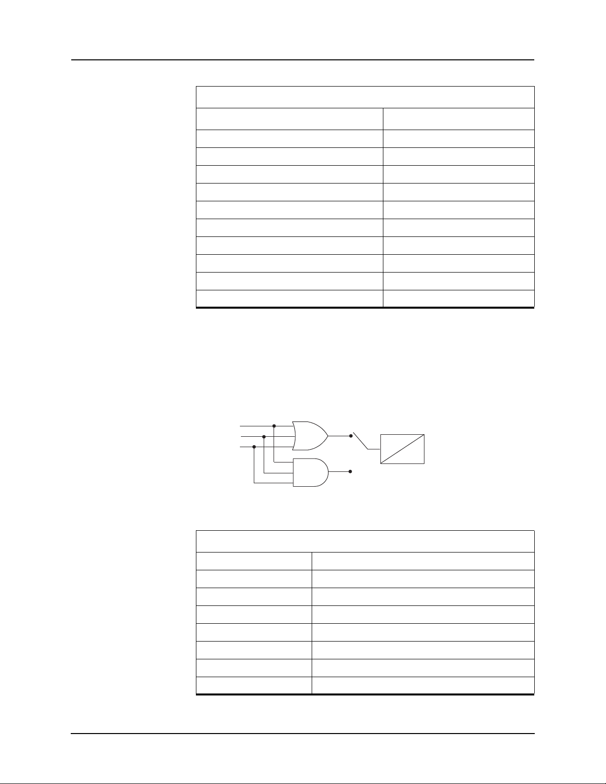
4 Protection Functions and Specifications
59 Va Main
59 Vb Main
59 Vc Main
T
O
OR
Gate Switch (Setting)
AND
79 Recloser
79 Recloser
Number of Shots 1 to 4
First Reclose (T1) 0.02 to 99.99 seconds
Second Reclose (T2) 1.00 to 99.99 seconds
Third Reclose (T3) 1.00 to 99.99 seconds
Fourth Reclose (T4) 1.00 to 99.99 seconds
Close Time (Tp) 0.01 to 1.00 seconds
Lockout Time (TD) 0.00 to 99.99 seconds
Initial Reset (TDI) 0.00 to 99.99 seconds
Block Reset (TDB) 0.00 to 99.99 seconds
Sync Control Enabled Enable/disable
Enable/disable
59 Overvoltage The F-PRO has a definite time delay main overvoltage function. This function
looks at all three phase-to-neutral voltages to determine an overvoltage condition. The logic gate can be set to either
AND or OR gate to detect all 3 phase
or any phase (of the 3 phases) overvoltage conditions. The definite time delay
can be set to 0.0 for a instantaneous trip.
4-10 F-PRO 5100 User Manual D02416R04.00
Figure 4.8: 59 Overvoltage
59 Overvoltage
59-1 Enable/disable
Gate Switch AND or OR
Pickup 1.0 to 138.0 volts
Pickup Delay 0.00 to 99.99 seconds
59-2 Enable/disable
Gate Switch AND or OR
Pickup 1.0 to 138.0 volts
Pickup Delay 0.00 to 99.99 seconds
Page 57
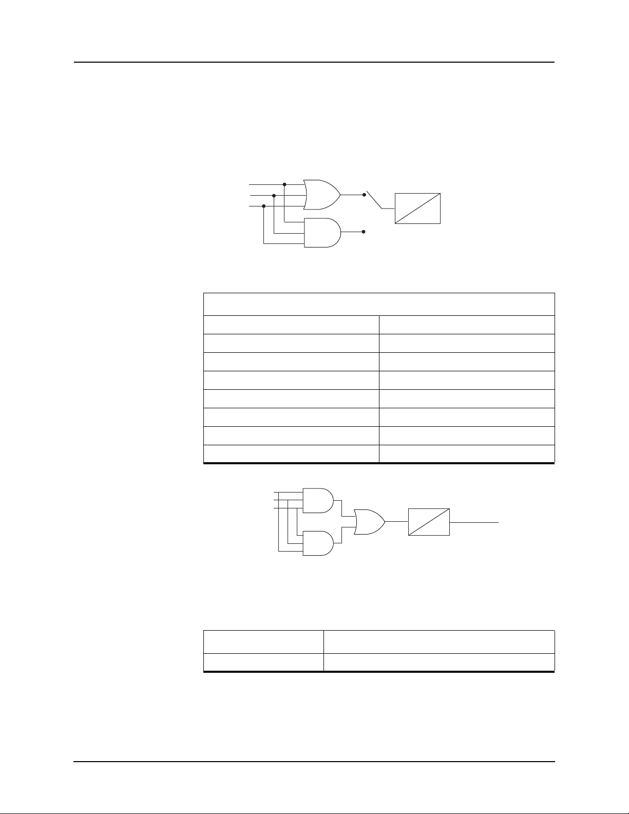
4 Protection Functions and Specifications
27 Va Main
27 Vb Main
27 Vc Main
T
O
OR
Gate Switch (Setting)
AND
207
206
197
10 s
0.0
59 VMainA (fixed 0.5 PU)
59 VMainB (fixed 0.5 PU)
59 VMainB (fixed 0.5 PU)
Loss of Potential
27 Undervoltage The F-PRO has a definite time main undervoltage function. The function looks
at the phase-to-neutral voltage of all three phases to make a determination of
an undervoltage condition. The logic gate can be set to either AND or OR gate
to detect all 3 phase or any phase (of the 3 phases) undervoltage conditions.
The definite time delay can be set to 0.0 for a instantaneous trip.
Figure 4.9: 27 Undervoltage
27 Undervoltage
27-1 Enable/disable
Gate Switch AND or OR
60 Loss of Potential
Pickup 1.0 to 120.0 volts
Pickup Delay 0.00 to 99.99 seconds
27-2 Enable/disable
Gate Switch AND or OR
Pickup 1.0 to 120.0 volts
Pickup Delay 0.00 to 99.99 seconds
Figure 4.10: 60 Loss of Potential
This function detects the loss of potential from either one or two phases of a
PT and issues an alarm.
60 Loss of Potential Enable/disable
D02416R04.00 F-PRO 5100 User Manual 4-11
Pickup Delay 10.00 seconds fixed
Page 58
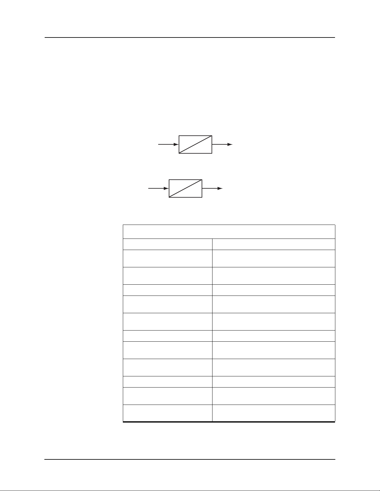
4 Protection Functions and Specifications
T
O
Frequency (Hz)
81 Frequency
The relay has four frequency devices available
set to operate either at a fixed level of under-frequency, a fixed level of overfrequency or at a rate of change level (df/dt). The df/dt function can be set to
operate for a positive rate of change or a negative rate of change. Each frequency element has a definite time delay setting to create
fixed level of positive sequence voltage of 0.25 pu or 5 volts whichever is
greater provides an undervoltage inhibit on each element.
Four frequency elements are provided, se
fixed level to rate of change.
Figure 4.11: Frequency Fixed Level
df/dt (Hz/s)
Figure 4.12: Frequency Rate of Change
. Each frequency element can be
a time delayed output. A
ttable from over/under frequency,
T
O
81 Over/Under Frequency
81-1 Disabled/Fixed Level/Rate of Change
Pickup 50.000 to 59.995 or 60.005 to 70.000 (fixed level)
-10.0 to -0.1 or 0.1 to 10.0 (rate of change)
Pickup Delay 0.05 to 99.99 seconds (fixed level)
0.20 to 99.99 seconds (rate of change)
81-2 Disabled/Fixed Level/Rate of Change
Pickup 50.000 to 59.995 or 60.005 to 70.000 (fixed level)
-10.0 to -0.1 or 0.1 to 10.0 (rate of change)
Pickup Delay 0.05 to 99.99 seconds (fixed level)
81-3 Disabled/Fixed Level/Rate of Change
Pickup 50.000 to 59.995 or 60.005 to 70.000 (fixed level)
Pickup Delay 0.05 to 99.99 seconds (fixed level)
81-4 Disabled/Fixed Level/Rate of Change
Pickup 50.000 to 59.995 or 60.005 to 70.000 (fixed level)
Pickup Delay 0.05 to 99.99 seconds (fixed level)
0.20 to 99.99 seconds (rate of change)
-10.0 to -0.1 or 0.1 to 10.0 (rate of change)
0.20 to 99.99 seconds (rate of change)
-10.0 to -0.1 or 0.1 to 10.0 (rate of change)
0.20 to 99.99 seconds (rate of change)
4-12 F-PRO 5100 User Manual D02416R04.00
Page 59
4 Protection Functions and Specifications
32P/32Q Directional Power
F-PRO provides directional real power and reactive power protection. Set the
pickup setting to a positive value (trip on forward power flow away from bus)
or a negative value (trip on reverse power flow into bus).
You can set either a real (32P) and a re
active (32Q) direction. The values are
set by specifying the pickup current. This value is set to positive values to detect power flow from the bus and to negative values to detect power flow
into
the bus.
32 Directional Power
32P Enable/disable
Pickup [-15.00, -0.25] to [15.00, 0.25] A (real)
Pickup Delay 0.00 to 99.99 s
32Q Enable/disable
Pickup [-15.00, -0.25] to [15.00, 0.25] A (reactive)
Pickup Delay 0.00 to 99.99 s
21P Phase Distance The relay has two mho phase distance elements. Each element includes a for-
ward reach and delta current supervisor setting. The
element output is only
available as a ProLogic.
21 Phase Distance
21P Enable/disable
Forward Reach 0.05 to 66.00 ohms
Delta Current Supervision 0.2 to 50.0 A
THD Alarm This function checks and picks the highest THD in any of the six current inputs
(if ring bus configuration is enabled). It only checks the three main current inputs for highest THD, if ring bus configuration is disabled.
THD Alarm
THD Alarm Enable/disable
Pickup 5.0 to 100.0%
Fault Locator When a fault occurs and the line trips, the fault locator calculates the fault type
and the distance to the fault. This information is available from the front display of the relay or through terminal UI,
or SCADA. Enable or disable the fault
locator through 50/51, 50N/51N and 46/50/51 respectively. Define the functions initiating the fault location when sett
ing.
D02416R04.00 F-PRO 5100 User Manual 4-13
Page 60
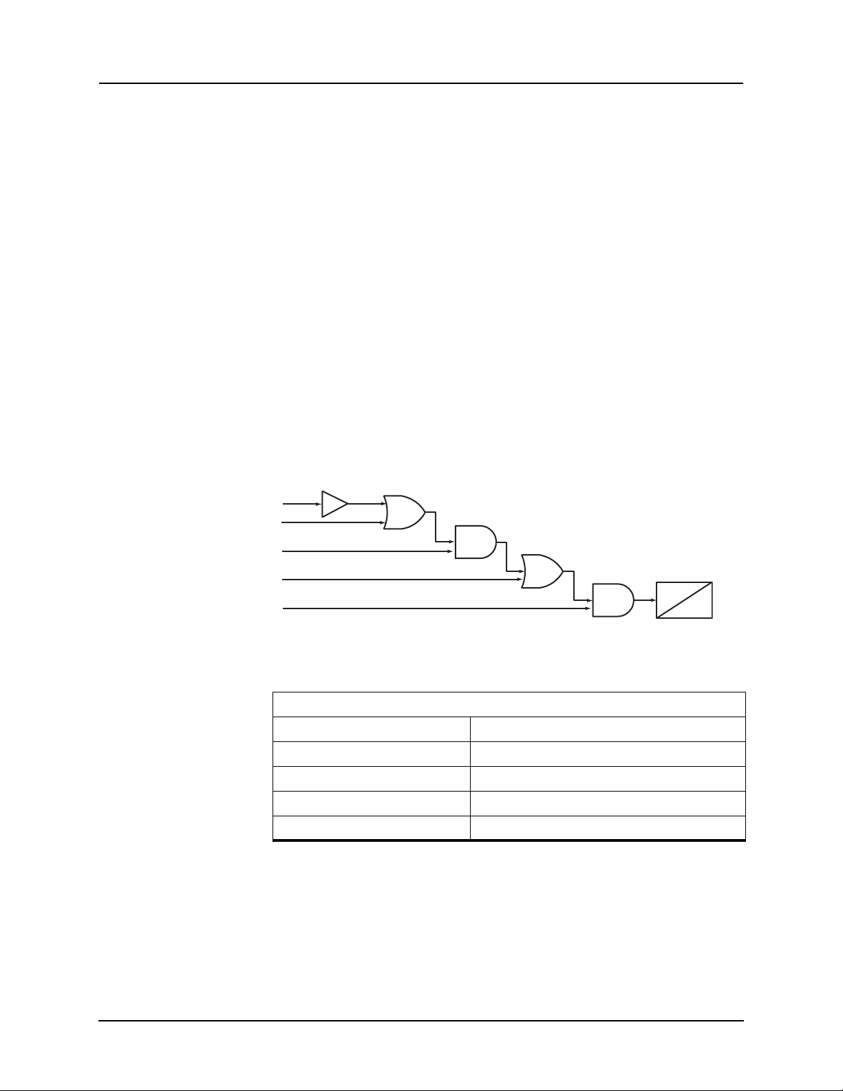
4 Protection Functions and Specifications
T
O
A
B
C
D
E
Op 1
Op 2
Op 3
Op 4
Op 5
ProLogic ProLogic Control Statements
Using ProLogic, F-PRO can pick any of the protection functions or external inputs and place them into Boolean-like statements
functions to generate one ProLogic statement; ten statements are possible. The
results from these statements are mapped to output contacts using the output
matrix.
Special ProLogic inputs are:
• Output relay #12 as an input to ProLogic.
The ProLogic control statements are
PRO can use any of the protection functions or external inputs combined with
logic gates to create a ProLogic control statement. The possible gates are AND,
NAND, OR, NOR, XOR, NXOR, and LATCH. The control can be time delay
pickup and or time delay dropout, and can drive the front panel target LED.
Ten ProLogic control statements outputs are available and can be used in the
output matrix to customize the relay to your specific needs. Inputs to ProLogic
are all the elements plus previous ProLogic statements for logic nesting usage.
The example shows A to E inputs are status
lectable. Each ProLogic output can be given a s
time delay.
. ProLogic handles up to five
used to create Boolean-like logic. The F-
points of devices that are user-se-
pecific name, pickup and reset
Figure 4.13: ProLogic
ProLogic Setting Functions
Name Give the ProLogic a meaningful name
Pickup Delay Delay time from pickup to operate
Dropout Delay Delay time from dropout to a ProLogic status of low
A, B, C, D, E Relay elements as input statements
Operators Boolean-type logic gates
4-14 F-PRO 5100 User Manual D02416R04.00
Page 61
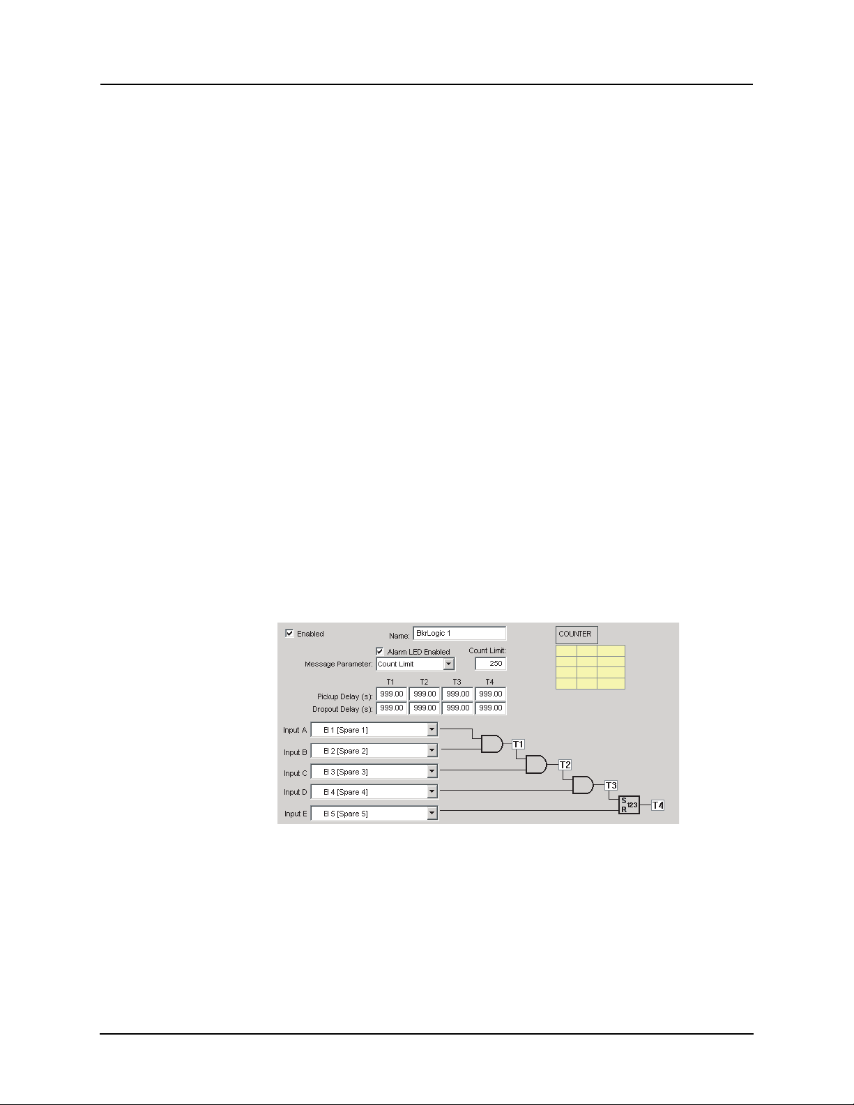
4 Protection Functions and Specifications
Breaker Monitoring The F-PRO breaker monitoring feature allows you to monitor the feeder break-
er(s) in detail. An accumulated I*I*t function
and ten user-definable logic
statements can be used to determine the status of breaker wear and breaker performance.
Breaker monitoring can be configured for me
anism time, trip coil energized time, operations count, fault operatio
asuring the clearing time, mech-
ns or other
user-defined conditions. Different users may require different feature sets to
monitor the breaker. The breaker monitoring functions are realized through the
Breaker Logic functions.
All associated breaker monitoring values are
available in the terminal UI and
SCADA interfaces. You can reset or preset all associated breaker monitoring
values from the terminal UI interface. You can only reset all associated breaker
monitoring values from the terminal SCADA interfaces.
Breaker Logic
The Breaker Logic function is similar to a ProLogic function, but includes
some additional features specifically for breaker monitoring allowing different
users to design their own breaker monitoring features by building different
breaker logic statements. Breaker Logic has additional timers on every output
of the logic statement, a total of four timers are available; a counter (including
settable count limit) is available in the last logic gate position. The front panel
Alarm LED can be enabled, and the logged message can be configured either
when one of the four timers has expired or when the counter limit has been exceeded. A total of 10 Breaker Logic functions are
available in the F-PRO.
The terminal UI and SCADA interfaces shows the status of each breaker logic
and associate
d counter. The terminal UI also includes the time of last reset/pre-
set.
Figure 4.14: Breaker Logic
For examples of breaker condition monitoring using Breaker Logic see “Setting Examples” in Appendix L.
D02416R04.00 F-PRO 5100 User Manual 4-15
Page 62

4 Protection Functions and Specifications
I*I*t
F-PRO has an accumulated I2t function used for monitoring the wear of the
breaker due to fault interruption. This function is available for both the main
breaker and the auxiliary breaker. The I
ation and stored in the non-volatile memory;
seconds. A fixed maximum write time of 20 seconds prevents the I
from constantly writing to non-volatile memory. Therefore if the start signal is
held on for longer than 20 seconds the accumulator will stop accumulating and
stop writing to the flash memory. The output I
in the event log, the output is not available in the output matrix or in the ProLogic input list.
The terminal UI and SCADA interfaces will show the accumulated value of
eac
include the time of last reset/preset.
The following figure shows the I
is started when the trip coil of the breaker is energized (breaker starts to open),
and will be stopped when the trip coil of the breaker is de-energized. The current that is used for accumulation is the
and C. An event message will be generated when the accumulated I
above the limit.
h breaker I
2
t value is accumulated for every oper-
the write time interval will be 0.5
2
t function
2
t function will only be available
2
t function and value of last operation. The terminal UI will also
2
t function's logic diagram. The accumulation
maximum current among Phase A, B
2
t value is
EI/PL For Trip Coil Energi zation
Logic 1 enabl es accumulati on to occur
Figure 4.15: I*I*t
IA
IBICMAX
enable accumulation
I^2T Accumulator
Read
FLASH
Wr i t e
4-16 F-PRO 5100 User Manual D02416R04.00
Page 63
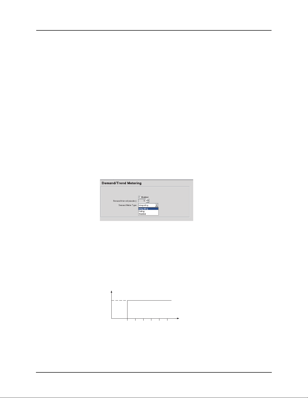
Demand Metering
The F-PRO has a demand metering feature which calculates the following
quantities:
• 3 phase real power send (MW)
• 3 phase real power receive (MW)
• 3 phase reactive power send (MVAR)
• 3 phase reactive power receive (MVAR)
• A Phase Current (A Pri)
• B Phase Current (A Pri)
• C Phase Current (A Pri)
• A Phase Voltage (V Pri, L-N)
• B Phase Voltage (V Pri, L-N)
• C Phase Voltage (V Pri, L-N)
• Frequency (in Hz)
• THD (in%)
You can select from three calculation types, integrating, rolling and thermal.
They are
4 Protection Functions and Specifications
described in detail below.
Figure 4.16: Integrating Demand Meter
Integrating demand meter is a linear average of the quantity over the demand
interval. Each new value only becomes available at the end of each time interval. The average is calculated from samples
taken every 0.5 seconds during the
demand interval. Therefore, the equation for calculating what the demand
quantity will be is based on the following equation:
New demand value = Sum of the samples during the demand interval /
(120*Demand Interval Setting)
1.0 PU
01 23 45
Figure 4.17: Step Power Input
time(minutes)
D02416R04.00 F-PRO 5100 User Manual 4-17
Page 64
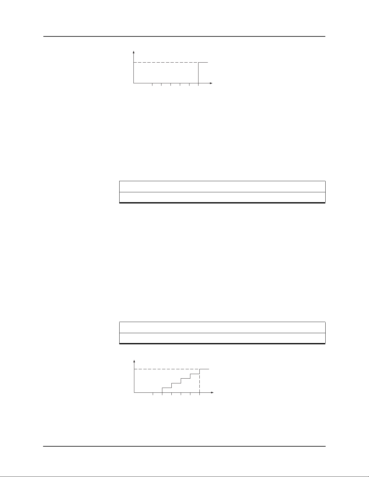
012345
time(minutes)
1.0 PU
4 Protection Functions and Specifications
time(minutes)
1.0 PU
01234
5
Figure 4.18: Integrating Demand Meter
Figure 4.17: Step Power Input on page 4-17 shows the input signal, which is a
magnitude of zero and then suddenly goes to an instantaneous level
unit, i.e. a step change function.
Figure 4.18: Integrating Demand Meter on page 4-18 shows the integrating demand meter, i.e. the demand val
end of the demand interval (setting, it's 5 minutes for this example). The response for integrating demand meter is shown in the
Time (min.) 1 2 3 4 5 6
Demand (% of Input) 0 0 0 0 100 100
of 1.0 per
ue will not be calculated or updated until the
following table:
Rolling Demand Meter
Rolling demand, also called “sliding window”, is a process by which intervals
are divided into a fixed number of subintervals. Instead of calculating demand
only at the end of each interval, the calculation is performed at the end of each
subinterval, and totaled and averaged for the interval. The subinterval is 1 minute (fixed) in F-PRO relay. The calculation is the same
as the Integrating De-
mand Meter.
Figure 4.19: Rolling Demand Meter on page 4-18 shows the rolling demand
meter response to the input of Figure 4.17: Step Power Input on page 4-17. The
demand value is calculated and updated on each subinterval (one minute). The
average ca
lculation is performed over the demand internal (setting, equal 5
minutes for this example). The response to the input shown in figure 1 for rolling demand meter is shown in the f
Time (min.) 1 2 3 4 5 6
Demand (% of Input) 20 40 60 80 100 100
ollowing table:
Figure 4.19: Rolling Demand Meter
4-18 F-PRO 5100 User Manual D02416R04.00
Page 65
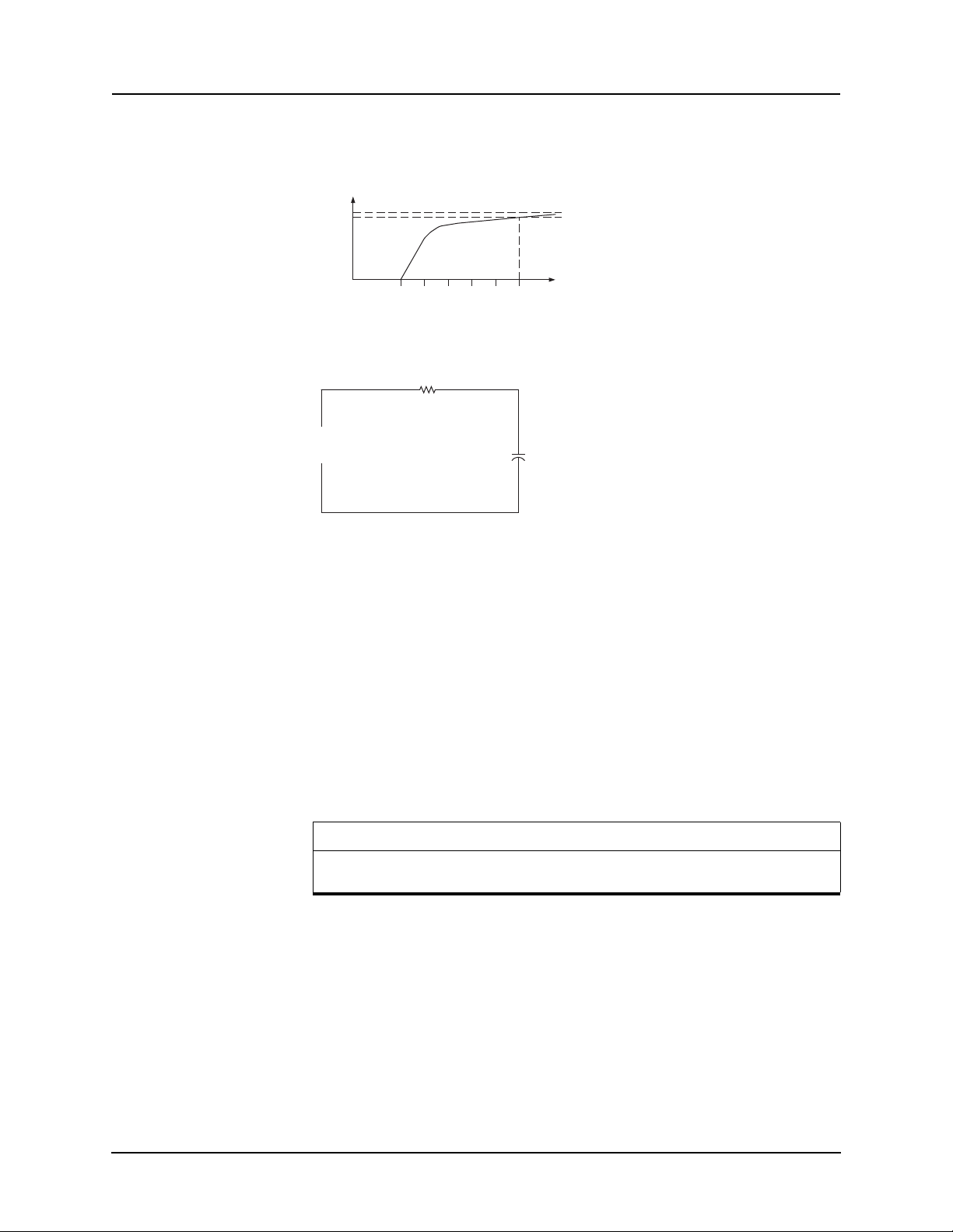
4 Protection Functions and Specifications
Thermal Demand Meter
The thermal demand meter is described in this section. Again, use the step
change power input from Figure 4.17: Step Power Input on page 4-17 as an example.
1.0 PU
0.90 PU
time(minutes)
01234
Figure 4.20: Thermal Demand
R
Vin
Figure 4.21: RC Circuit
5
C
Vout
Figure 4.20: Thermal Demand on page 4-19 shows the thermal model of demand calculation. It acts like a RC circuit as shown in Figure 4.21: RC Circuit
on page 4-19. The output voltage will never reach the final value until the ti
goes to infinity, however, we define it in this way i
t will reach the 90% of the
me
input when the elapsed time is equal to the Demand Interval (5 minutes for this
example). The thermal demand will reach 99% of the input when the time is
twice of the demand interval, as shown in the table below. The equation for this
response is Vout = Vin*(1-e-t/), where is the time constant and it is equal to
2.17147241 minutes. The thermal demand meter data will be calculated and
updated every half-second. The following table shows the response of the thermal demand.
Time (min.) 1 2 3 4 5 6 7 8 9 10
36.9 60.1 74.8 84.1 90 93.6 96 97.4 98.4 99
Peak Demand Quantities
Demand (%
f Input)
o
Peak Demand quantities will be derived from the Demand/Trend quantities. A
total of 7 Peak Demand Quantities will be metered:
• 3 Phase Real Power Out (MW)
• 3 Phase Real Power In (MW)
• 3 Phase Reactive Power Out (MVAR)
• 3 Phase Reactive Power In (MVAR)
• A Phase Feeder Current IA (A Pri)
• B Phase Feeder Current IB (A Pri)
D02416R04.00 F-PRO 5100 User Manual 4-19
Page 66

4 Protection Functions and Specifications
• C Phase Feeder Current IC (A Pri)
The peak demand quantities are available from the front panel display, the TUI
metering and SCADA. Peak Demand quantities can be reset from the front
panel, TUI or SCADA. The peak value of the above quantities and the time of
occurrence are displayed.
Accumulated Energy (kWh, kVARh metering)
For the accuracy and the consistency, the method of the energy calculation is
the same regardless of the demand type. (rolling, integration, thermal). There
are four accumulated energy quantities. They are:
• 3 Phase real energy OUT (MWh)
• 3 Phase real energy IN (MWh)
• 3 Phase reactive energy OUT (MVARh)
• 3 Phase reactive energy IN (MVARh)
The accumulated energy quantities are calculated by the integration of the average power over the elapsed time. This calculation is carried out once per minute, however the actual power is sampled every half second and averaged every
minute (120 samples).
The accumulated energy quantities are stored in the non-volatile memory to
avoid the data loss on power down.
When the accumulated energy quantities exceed 98000 MWh/MVARh they
are reset to zero. A reset on one energy quantity will only reset it's own value,
not the other energy quantities. All reset actions will be logged in the event log.
4-20 F-PRO 5100 User Manual D02416R04.00
Page 67

Group Logic Group Logic Control Statements
The F-PRO relay has eight setting groups (SG). You can change all relay setting parameters except the physical connections such as input or output parameters in each setting group. Setting group changes are performed by using any
one of the 16 available Group Logic statements per setting group. The Group
Logic statements are similar to the ProLogic statements with the following ex
ceptions—the sole function is to activate one of the eight setting groups and the
processing is in a slower half second cycle. Group Logic input statements are
driven from ProLogic, any external input, previous Group Logic statements or
virtual inputs. Each Group Logic statement includes five inputs (with Boolean
statements), one latch state and one pickup delay timer. The active setting
group (ASG) is viewed from the Terminal Mode, the front panel or from a re
cord stored by the relay (the active setting group is stored with the record).
Group Logic Processing
The sixteen Group Logic statements reside in a slower processing thread within the relay protection algorithms. The processing cycle happens once every
half second (0.5 second). When using ProLogic statements remember that a
latch or dropout timer should be used if the initiating condition does not last at
least 0.5 seconds. In the example following, we will create a definite pulse
length using ProLogic. For details see
L.
4 Protection Functions and Specifications
-
-
“F-PRO Setting Example” in Appendix
Default Setting Group
The relay uses Setting Group 1 as the factory default setting group and retains
the current active setting group in memory. This allows the relay to use the last
active setting group prior to interruption of relay power as the default setting
group following power up.
D02416R04.00 F-PRO 5100 User Manual 4-21
Page 68
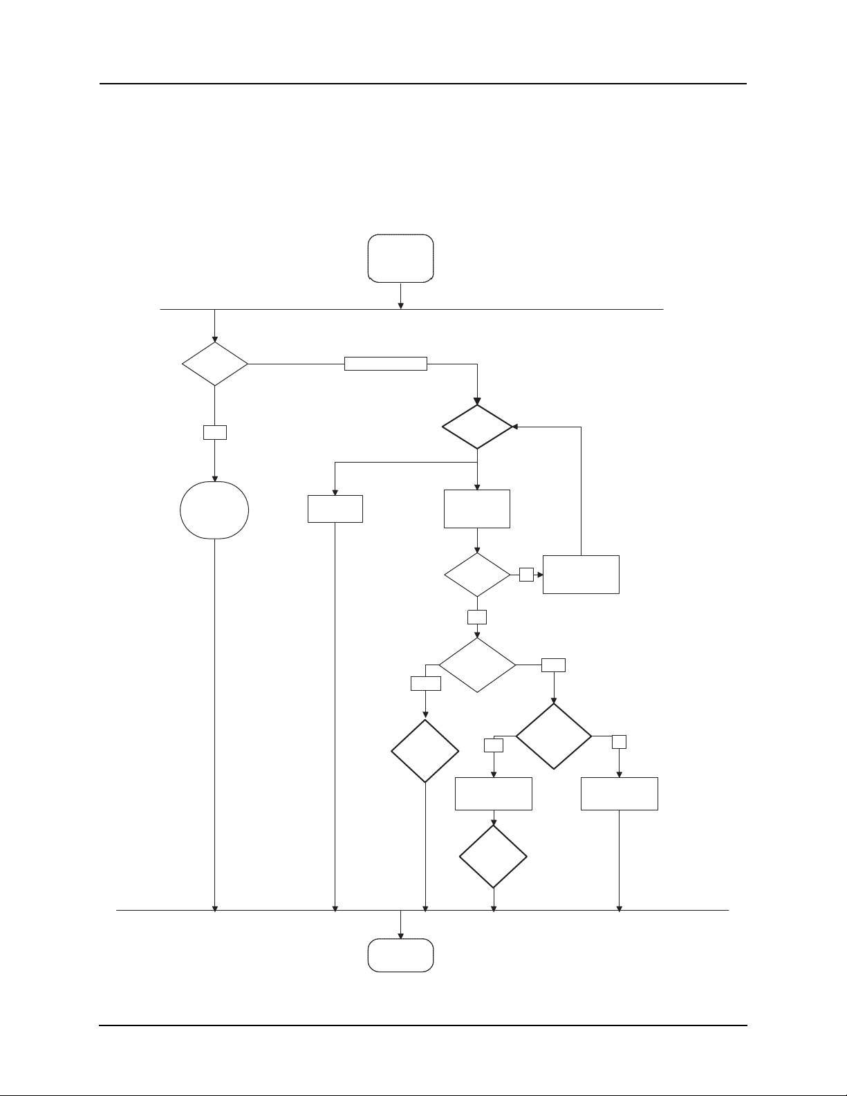
4 Protection Functions and Specifications
Active
Group
Screen
Change or Service
View
Access
Level
F2
Yes
Validate
User I/P
Invalid
Error
Msg
Any Key
Valid
View Only select <F2>
or <F3> to
continue
Confirm
Setting
Change
ASG
modied
System
refreshes AG
Screen
No
System
changes AG
Yes
System cancels
AG change
No
Quit
Settings
User
Decision
Satus
Msg
Any Key
Change Active Group
You can at any time change the active setting group. When you initiate a setting group change, this change
group change. The terminal UI is used to change the active setting group. To
view a snapshot of the group logic data select F2 prior to making any modification to the Active Setting Group input. The following is the flow of events
that
takes precedence over an automatic setting
can occur in the Active Group Screen.
4-22 F-PRO 5100 User Manual D02416R04.00
Page 69
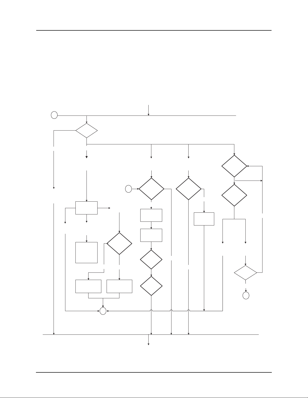
4 Protection Functions and Specifications
s
Settings Saved
You can change the active setting group while saving setting changes or loading settings from Offliner. The relay prompts you for
vate— you can keep the current setting group or
a setting group to acti-
switch to a new setting group
following the settings save.
The following is the flow of
events that can occur in the Editing Settings
Screen.
Edit
Settings
B
Access
Level
View
<F3> Quit
<Enter> view
Change or Service
Exit
Select Copy
Group
System
opens Copy
SG Screen
CR or
Space
System
updates Copy
SG x to SG y
and waits for
User I/P
System cancels
SG x to SG y
No
System copies
SG x to SG y
Copy
group
Confirm
Setting
Copy
Yes
Quit
User
Selects
Settings
User
Enters
Settings
Ye
Accept
Changes
Accept
Changes
Confirm
A
Setting
Load
Yes
System
Saves all
Changes
System asks
user for SG
to activate
SG to
No
Quit
Quit
without
Save
No
System
keeps
Changes
Activate
Satus
Msg
Any Key
Yes
System In
Entry Level
No
A
B
Settings
D02416R04.00 F-PRO 5100 User Manual 4-23
Page 70
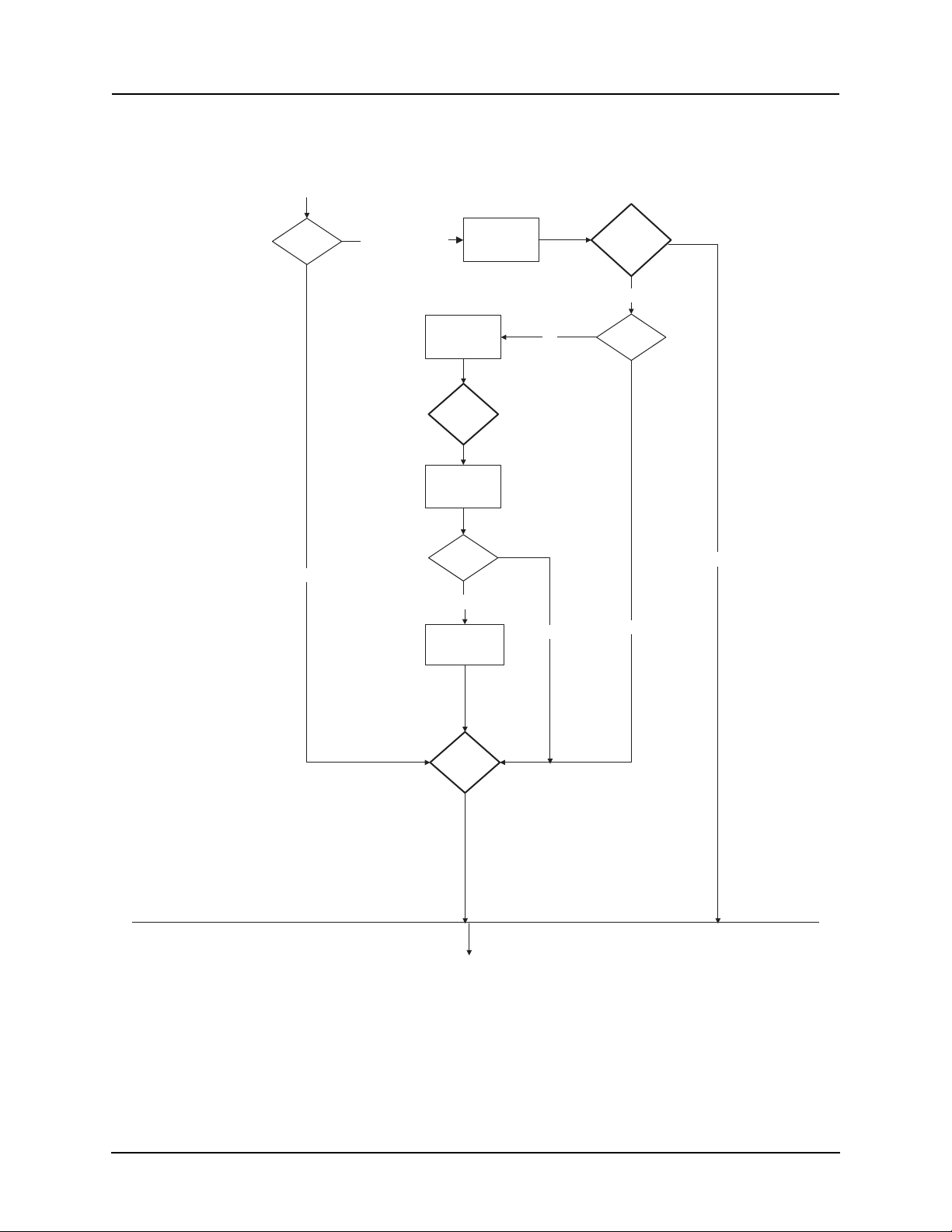
4 Protection Functions and Specifications
The following is the flow of events that can occur in the Load Settings Screen.
Load
Settings
Access
Level
View
Change or Service
receives user
System Saves
System opens
Load Setting
System
file
SG to
Activate
System
processes
user file
File
Correct
Yes
all Changes
Screen
No
No
Confirm
Setting
Load
Yes
System
Timeout
Yes
No
Status
Msg
Any Key
Settings
4-24 F-PRO 5100 User Manual D02416R04.00
Page 71

4 Protection Functions and Specifications
Manual Settings Change
Relay configuration changes during a user-initiated manual setting; the change
does not disrupt the relay protection functions. The relay logs an acceptance of
the change request and puts the new setting file in service. When the new setting file is queued the relay loads the new setting configuration for protection
functions to
the protection processor. The relay loads the new name definitions
for indication and recording functions to the interface processor. When the relay has completed loading the ancillary settings for indication purposes
to the
interface processor, an event is logged to show completion of the request.
There is some lag time during the load request and the completion of the request where the interface processor
vious setting file for approximately five seconds. The ancillary setti
associates ancillary functions with the pre-
ng
information includes channel or ProLogic and Group Logic statements names,
front panel target light activation rules and record initiation rules.
The protection processor does not have any interruption in service.
Automatic Settings Change
Relay configuration changes during a relay-initiated setting; change does not
disrupt the relay protection functions. Since the relay setting file does not
change, the interface processor uses the new setting group ancillary setting information at the same time as the prote
ting group. An event is logged to show when
ction processor switches to the new set-
the new setting group is in
service.
D02416R04.00 F-PRO 5100 User Manual 4-25
Page 72

4 Protection Functions and Specifications
Recording Functions
The F-PRO has recording and logging functions to allow you to analyze faults
and to review the operation of the overall protection scheme.
Fault Recording The F-PRO provides high quality fault recording, capturing input signal wave-
forms and external digital inp
record also contains the timing of the internal logic produced by the relay (e.g.
51 trip).
The quantities recorded are:
• 10 analog channels: 4 voltages an
the 25th harmonic frequency response
• 9 external digital inputs: @ 96 samples/cycle
• relay internal logic signals: @ 8 samples/cycle
• summation channels
Trend Recording The trend recording provides continuous, slow-speed recording of P, Q, Ener-
gy, V, I, Freq. and THD of the feeder with an adjustable sa
to 60 minutes per sample. This same global trend sampling rate is applied to all
the trend quantities. The relay stores a fixed number of samples. At the nominal
sample period of 5 minutes per sample the F-PRO stores one month of trend
records with automatic overwrite of the oldest.
ut states at a rate of 96 samples per cycle. Each
d 6 currents @ 96 samples/cycle, up to
mple period from 5
Sample Interval Trend Record Length
5 minute 30 days
10 minute 60 days
30 minute 180 days
60 minute
360 days
Record Initiation Recording can be initiated automatically by the relay when a fault or abnormal
condition is detected. You can set the relay to initiate a fault record upon activation of any of its trip or alarm functions or on
assertion of any external digital
inputs.
The assignment of fault record
initiation to the various relay functions is done
through the relay’s Output Matrix settings.
A recording can also be initiated manually through the t
erminal user interface.
The command Initiate Fault Recording is available under the Records menu.
4-26 F-PRO 5100 User Manual D02416R04.00
Page 73

4 Protection Functions and Specifications
Record Duration and Extension
The length of each record is determined by the Record Length setting. Fault record lengths can be set between 0.2 and 2.0 seconds. Pre-trigger times are fixed
at 10 cycles for fault records and are included as part of the normal record
length. A trend recording is for a 30 day period at one sample/5 minutes. You
do not need triggers to create a trend record.
The F-PRO automatically extends a record as required to capture consecutive
triggers that are close together. If a trigger occurs while a recording is in prog
ress, the record is stretched to include the full post-trigger time of subsequent
triggers, up to a maximum length—2.0 seconds for fault records. If a trigger
occurs before the end of a record caused by a previous trigger, but too late to
allow sufficient post-trigger time in a maximum extended record, a new over
lapping record is created.
The normal record lengths settings are accessible under the Recording heading
of the relay settings, and can be set from either the terminal user interface or
the Offliner Settings software.
Event Recording The event recording provides permanent storage of the event log. An event re-
cord can be created automatically or manually. When the event auto save is enabled an event record is created approximately every 230 events.
A recording can also be initiated manually through the terminal user interface.
The command Initiate Event Recording is available under the Records menu.
-
-
Record Storage The F-PRO compresses records on the fly, achieving a typical lossless com-
pression rate of 4:1. As a result, the F-PRO can store up to 30 seconds of fault
recordings and a minimum of 30 days of trend recordings in non-volatile stor
age. If the storage is full, new records automatically overwrite the oldest, ensuring that the recording function is always available.
Retrieval and Analysis
A listing of stored records is available through the terminal user interface under
the Records menu. The listing provides the means to transfer records to a con
nected PC and to delete them from storage.
Example:
FPRO-5100-990726-04-2000-06-09 13.17.16.000(Fault)
Records are named by combining the Relay ID setting with the date and time
of the initiating record trigger. In the record list, the record type (fault or swing)
is shown.
To delete a record from storage, use the up/down cursor keys to select the record, then press <D>. You can also do group deleting and group transferring.
To select multiple records:
1 Select a record.
2 Press the spacebar - a asterisk will appear to the left of the record to indicate
it is selected.
3 Continue selecting and pressing the spacebar until all desired records are
selected.
4 Press <D>. A message asks “Delete all selected files?” shown above. Select
Y for Yes and the files are deleted.
-
-
D02416R04.00 F-PRO 5100 User Manual 4-27
Page 74

4 Protection Functions and Specifications
To transfer a record to your PC, use the up/down cursor keys to select the record, then press r. The record is automatically transferred to
your PC using the
PC terminal program’s z-modem file transfer protocol. The record is placed in
your terminal program’s default to receive the directory which was set before
transfer to an appropriate directory. (e.g. HyperTerminal’s default receive directory is set through the its Transfer menu). When tra
nsferred, the record
name remains unchanged and the file extension indicates the record type:
“.fpr” for fault, “.fpe” and “.fpt” for trend.
When the transfer has taken place, you can choose
to delete the record or leave
a copy on the relay.
Logging Functions
Event Log The F-PRO maintains a log of events in a 250 entry circular log. Each entry
contains the time of the event plus an event description.
Logged events include trips, alarms, external input a
events such as setting changes. Fault location and classification information is
included in event messages where appropriate. For example, the event log entry for a device trip might be:
2000 Nov 21, 15:34:19.832 : 51 ABC 112.3 km: Trip.
The event log can be viewed in
two ways:
ssertions plus internal
Front Panel The front panel display shows events in abbreviated form (Trip
and Alarm events only).
Terminal User Interface The full event log is available through the Event Log menu of the
erminal user interface.
t
This display is a snapshot of the event list which must be manually
refreshed to display new events that occur while the display is up.
There is a list of the F-PRO event messages. For details see “Event Messages”
in Appendix D.
4-28 F-PRO 5100 User Manual D02416R04.00
Page 75
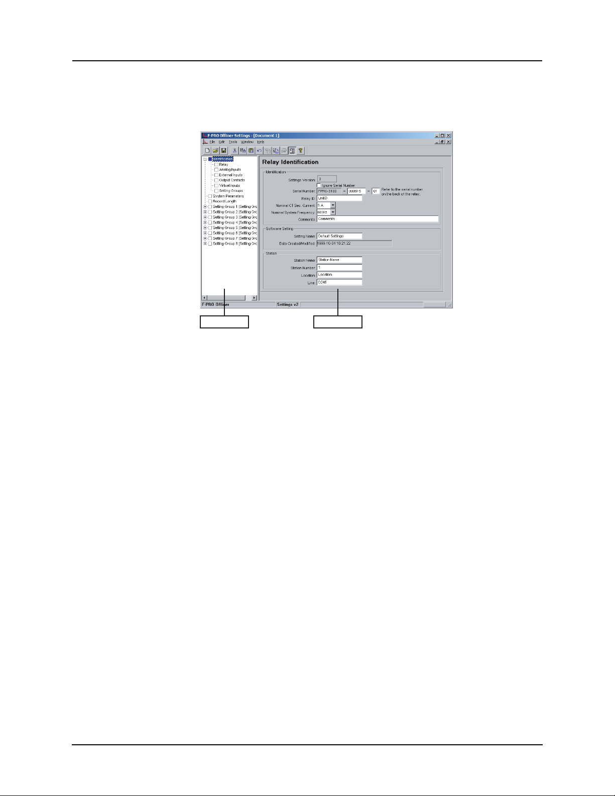
5 Offliner Settings Software
Setting Tree Setting Area
Figure 5.1: Opening Screen
Introduction
PC System
Requi
rements
Use the Offliner Settings software to create relay settings on a PC. Offliner Settings provides an easy way to view and manipulate settings.
Hardware
The minimum hardware requirements are:
• 1 GHz processor
• 2 GB RAM
• 20 GB available hard disk space
• USB port
• Serial communication port
Operating System
The following software must be installed and functional prior to installing the
applications:
• Microsoft Windows XP Professional Service Pack 3 or
• Microsoft Windows 7 Professional Service Pack 1
D02416R04.00 F-PRO 5100 User Manual 5-1
Page 76
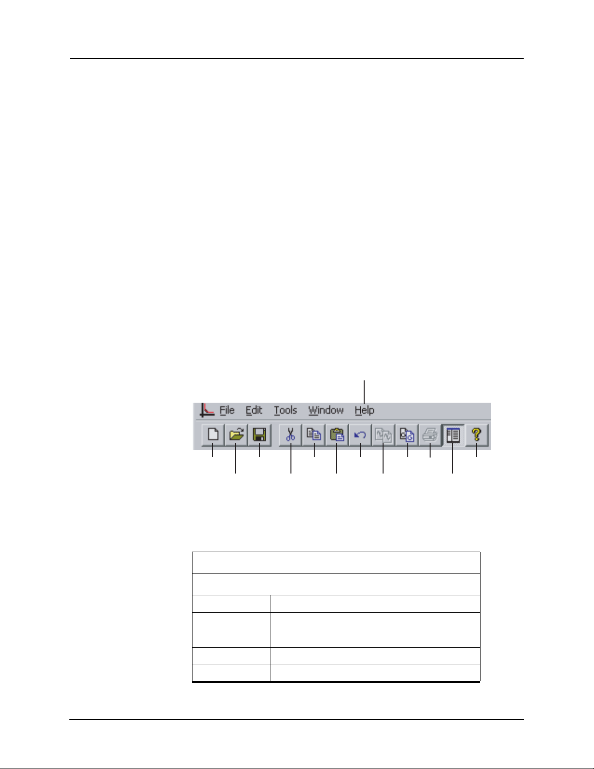
5 Offliner Settings Software
Installing PC Software
Insert the CD-ROM in your drive. The CD-ROM should open automatically.
If the CD-ROM does not open automatically, go to Windows Explorer and find
the CD-ROM (usually on D drive). Open the F-PRO.exe file to launch the CDROM.
Offliner Features
To install the software on your computer, click the de
sired item on the screen.
The installation program launches automatically. Installation may take a few
minutes to start.
To view the F-PRO User Manual you must have Adobe Acrobat on your computer. If you need a copy, download a copy by clicking on Download Adobe
Acroba
Anti-virus/Anti-spyware Software
t.
If an anti-virus/anti-spyware software on your local system identifies any of
the ERLPhase applications as a “potential threat”, it will be necessary to configure your anti-virus/anti-softw
ation. Please consult the appropriate
are to classify it as “safe” for its proper oper-
anti-virus/anti-spyware software
documentation to determine the relevant procedure.
The Offliner software includes the following menu and system tool bar.
Help - Help Topics
About F-PRO Settings
New Save Copy
Open Cut Paste
Figure 5.2: Top Tool Bar
Too l B ar
Windows Menu
Icon Restore, minimize, close.
File New, open, close, save, save as, print setup.
Edit Undo, cut, copy, paste.
Tools Display and print only enabled protection devices.
Window Cascade, tile, arrange icons.
5-2 F-PRO 5100 User Manual D02416R04.00
Undo
Copy
Graph
Copy
Setting
Group
Print
Show or Hide
Left-Hand Side
Tree
About
Page 77

Help Help Topics, About F-PRO Settings.
Settings Program Icons
New Create new default settings file.
Open Open any valid settings file.
Save Save current settings file.
Cut Edit function.
Copy Edit function.
Paste Edit function.
Undo Edit function.
Copy Graph Copy to clipboard.
5 Offliner Settings Software
Graphing Protection Functions
Copy Setting
Group
Print Print from Output Matrix, any graph or Settings Summary.
Show or Hide LeftHand Side Tree
About Version number.
Copy from Setting Group X to Setting Group Y.
Show or Hide Left-Hand Side Tree
Grid On/Grid Off
The graph can be viewed with the grid on or off by clicking the Grid On or Grid
Off button. A right-click on the trace of the curve gives you the x and y coor
dinates.
Print Graph
To print a particular graph, click the Print Graph button.
Zoom on Graphs
Graphs can be zoomed to bring portions of the traces into clearer display. Leftclick on any graph and drag to form a small box around the graph area. When
you release the mouse, the trace assumes a new Zoom position determined by
the area of the zoom coordinates.
To undo the zoom on the graph, click the Refresh button.
-
D02416R04.00 F-PRO 5100 User Manual 5-3
Page 78
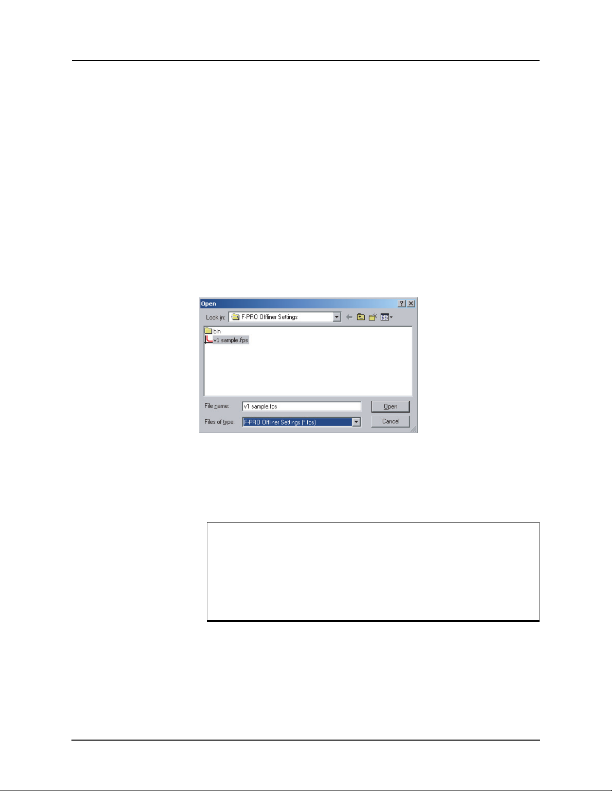
5 Offliner Settings Software
Handling Backward Compatibility
Offliner Settings displays the version number in the second pane on the bottom
status bar. The settings version is a whole number (v1, v2, v3, v4, etc.).
The Off
files and convert older settings files to a newer version. Offliner Settings handles forward conversion only; it
file.
liner Settings is backward compatible. Open and edit older settings
converts an older setting file to a newer setting
Converting a
Settin
gs File
Sending a New Setting File to the Relay
1 Open the setting file you wish to convert.
2 In the File menu, sele
ct Convert to... and then select the version x (where x
is the newer version). A dialog box pops up prompting Offliner for a new
file name. Use either the same file name or enter a new file name. The conversion process inserts default values for any newly added devices in the
new setting file. When t
he conversion is complete, Offliner Settings dis-
plays the new file.
Figure 5.3: Converting Setting Files
1 Make sure the settings version and the
ting file match. The relay will reject the setti
serial number of the relay in the set-
ng file if either the serial num-
ber or the settings version do not match.
A “serial number discrepancy” message may appear. This is to ensure that you are aware of the exact relay in which settings are to
be
loaded. If this happens, check the relay serial number using the
terminal mode ID menu item. Type this serial number into the FPRO Serial No. box in the Identification tab display area of Offliner
Settings. Alternately you may check the Ignore Serial Number
check box to bypass serial number supervision.
2 Check the serial number and the setting
s version of the relay, for details see
“ID” on page 3-11. The Device Serial Number and Required Settings Version on the Identification screen indicate
the serial number and the settings
version of the relay.
5-4 F-PRO 5100 User Manual D02416R04.00
Page 79
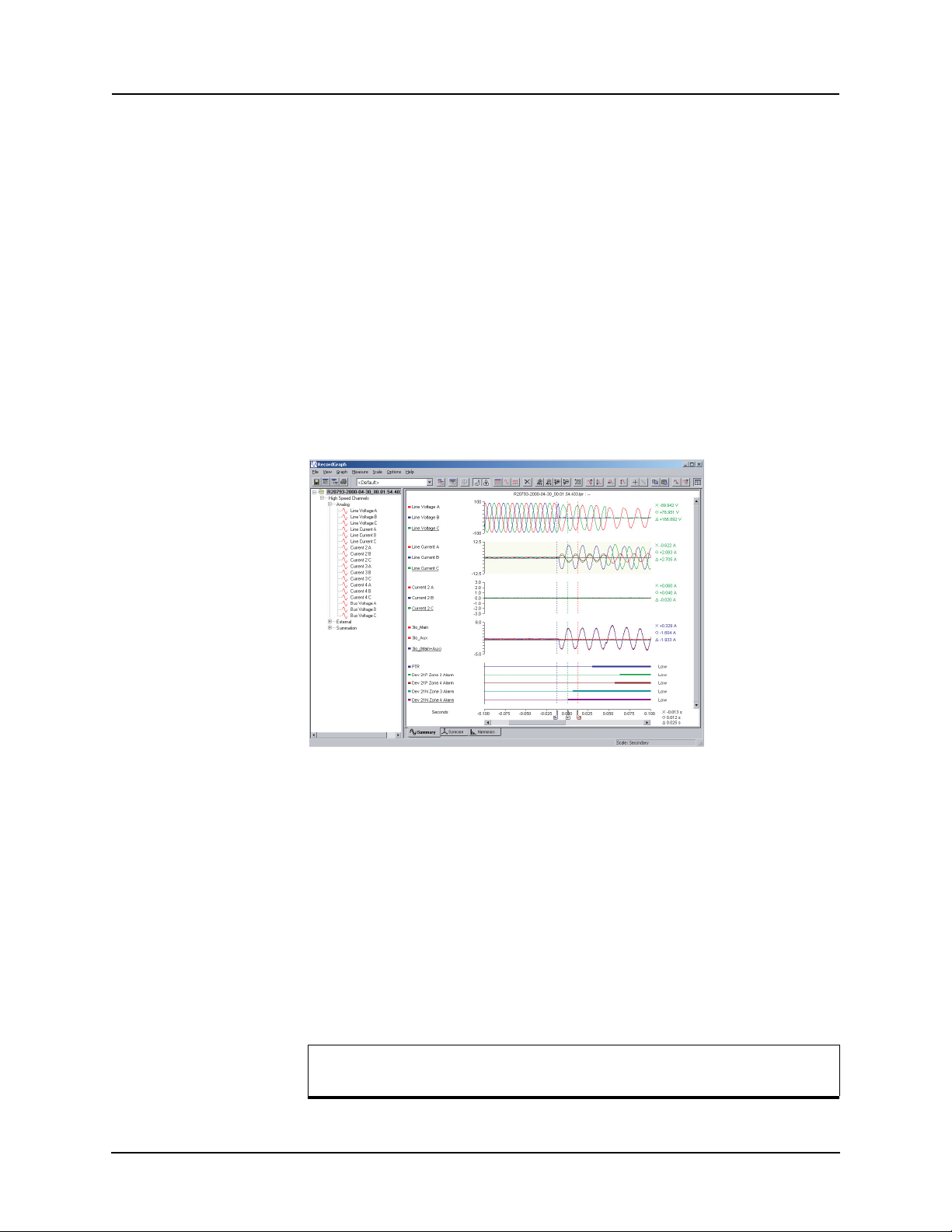
5 Offliner Settings Software
Creating a Setting File from an Older Version
1 Offliner Settings displays a default setting file on start up showing the set-
tings version in the bottom statu
shipped with a set of default sample files of older settings versions. The
sample file is “v1 sample.fps”. The sample file contains default values of
an older settings version. For a new installation these sample files are
placed in the default directory C:\Program Files\ERLPhase\F-PRO Offliner
Settings, or you can choose the path during the Offliner software installation. If an older version of F-PRO Offliner was previously installed on your
then the default directory may be C:\Program Files\APT\F-PRO Of-
PC,
fliner Settings.
2 Open a sample file of the desired version. Use File/Save A
ple file to a new file name. Then edit the
save it and load it into the relay.
RecordBase View Software
s bar. As an example F-PRO Offliner is
s to save the sam-
setting file and the serial number,
Figure 5.4: RecordBase View
Use RecordBase View to analyze the records from a relay.
1 Set the receive directory on your terminal program to point to
a convenient
directory on your PC’s hard disk or network. For example with HyperTerminal, select Trans
2 Select one or more records on the relay using the Li
minal Mode’s Records me
3 Initiate transfer of the selected records by selecting R o
fer>Receive File to set the receive directory.
st function in the Ter-
nu.
n the keyboard.
4 Start the RecordBase View program and use the File>Open menu command
to
open the downloaded record files located in the receive directory speci-
fied in step 1.
For further instructions refer to the RecordBase View Manual at the
back o
D02416R04.00 F-PRO 5100 User Manual 5-5
f the printed version of this manual.
Page 80
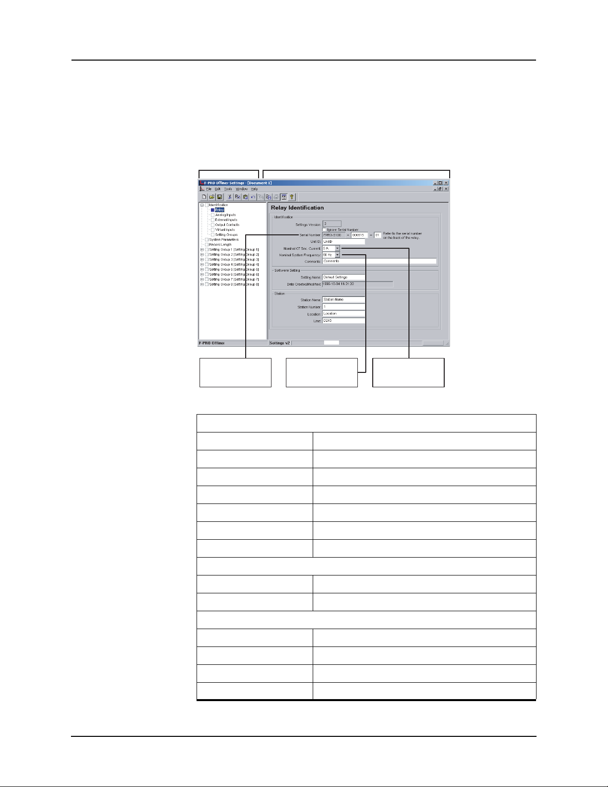
5 Offliner Settings Software
LHS Menu Tree
RHS - Information relating to specific menu Item,
accessed by LHS menu or top tabs.
Unique relay serial
number
Nominal System
Frequency - set to
either 50 Hz or 60 Hz
Nominal CT Sec.
Current - set to either
1 A or 5 A
Main Branches from the Tree View
Identification The first screen presents all the menu items in the left menu tree. Access the
menu items by clicking on item on the left menu tree.
Relay
Figure 5.5: Identification
Identification
Settings Version Indicates the settings version n
Ignore Serial Number Bypass serial number check, if enabled.
Serial Number Available at back of each relay.
Unit ID User-defined up to 20 characters.
Nominal CT Format 5 A or 1 A
Nominal System Frequency 60 Hz or 50 Hz
Comments User-defined up to 20 characters.
Setting Software
Setting Name User-defined up to 20 characters.
Date Created/Modified Indicates the last time settings were entered.
Station
Station Name User-defined up to 20 characters.
Station Number User-defined up to 20 characters.
Location User-defined up to 20 characters.
umber, fixed.
Line User-defined up to 20 characters.
5-6 F-PRO 5100 User Manual D02416R04.00
Page 81
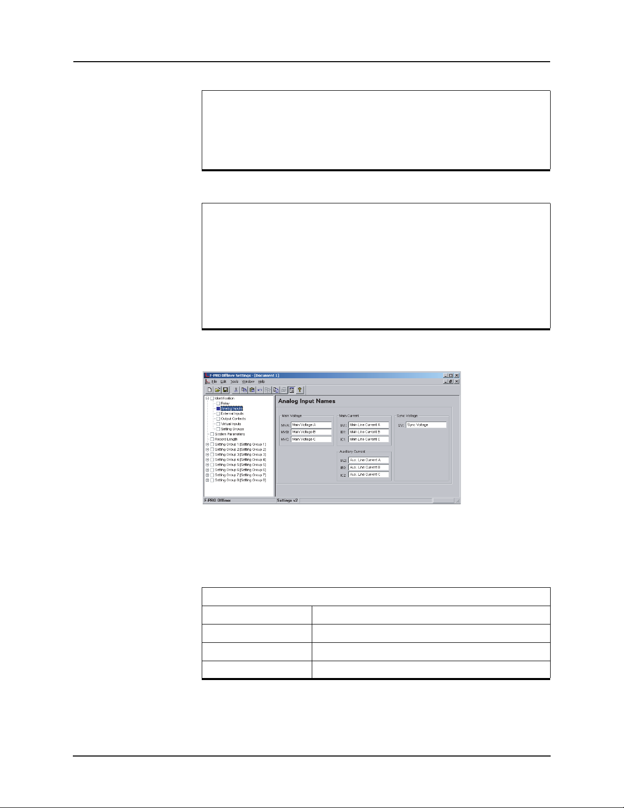
5 Offliner Settings Software
Important Note
Nominal CT Sec. Current can be set to either 5 A or 1 A.
Nominal System Frequency can be set
to either 60 Hz or 50 Hz.
Ensure setting selection matches that of target F-PRO.
The serial number of the relay must match the one in the setting file,
he setting will be rejected by the relay. This feature ensures that
or t
the correct setting file is applied to the right relay.
In Settings Version 2 or greater you can choose to ignore the serial
number e
nforcement in the identification screen. The relay only
checks for proper relay type and setting version if the ignore serial
number has been chosen, requires relay firmware version 2.0 or
greater.
Analog Inputs
Figure 5.6: Analog Inputs
Analog Inputs screen identifies all the ac voltage and current inputs to the relay. These names appear in any fault disturbance
Analog Inputs
Main Voltage MVA, MVB, MVC
Main Current IA1, IB1, IC1
Aux. Current IA2, IB2, IC2
Sync Voltage SV
D02416R04.00 F-PRO 5100 User Manual 5-7
records the F-PRO produces.
Page 82
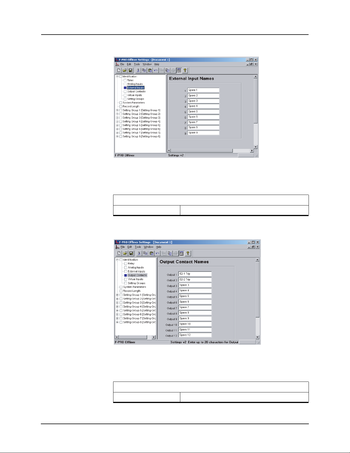
5 Offliner Settings Software
External Inputs
Figure 5.7: External Inputs
The External Inputs screen allows you to define meaningful names for nine external inputs.
External Input Names
1 to 9 User-defined
Output Contacts
Figure 5.8: Output Contacts
The Output Contact Names screen allows you to define meaningful names to
the 12 output contacts.
Output Contact Names
Outputs 1 to 12 User-defined
5-8 F-PRO 5100 User Manual D02416R04.00
Page 83
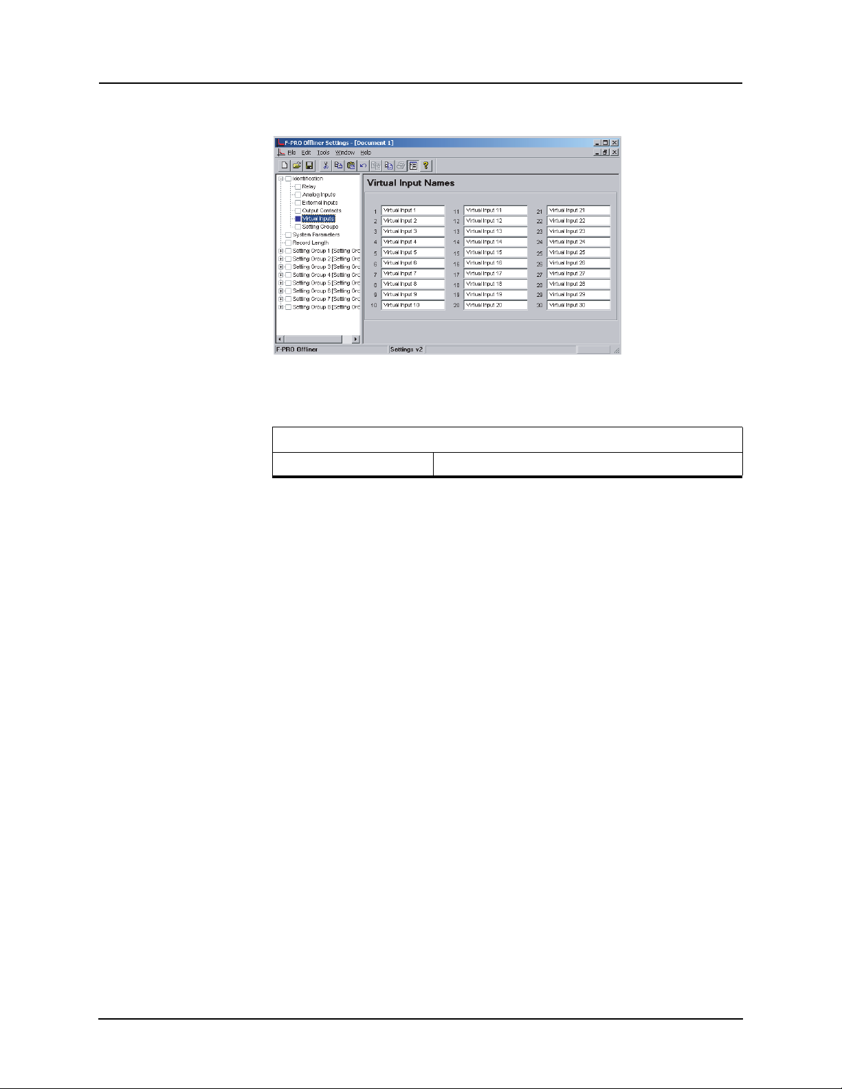
Virtual Inputs
Figure 5.9: Virtual Inputs
Virtual Inputs
Virtual Inputs 1 to 30 User-defined
5 Offliner Settings Software
The relay can control its internal functions and connected devices both
locally and remotely. Thirty general purpose logic points are accessible
via DNP3 and the terminal UI. The 30 virtual inputs are individually
controlled and include a set, reset and pulse function. The latch state is
retained during setting changes and relay power down conditions. The
30 virtual inputs conform to DNP3 standards. Use the DNP3 functions
such as SBO (select before operate), Direct Operate, or Direct Operate
with no acknowledge to control virtual inputs.
Use virtual inputs to:
• control circuit breakers
• enable or disable reclosing
• enable or disable under-frequency load
• change setting groups
• provide interlocking between local/remote supervisory control
shedding
D02416R04.00 F-PRO 5100 User Manual 5-9
Page 84
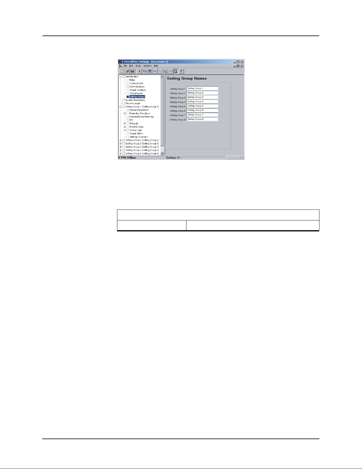
5 Offliner Settings Software
Setting Groups
Figure 5.10: Setting Groups
The Setting Group Names screen allows you to define meaningful
names to the 8 setting groups.
Setting Groups
Setting Groups 1 to 8 User-defined
5-10 F-PRO 5100 User Manual D02416R04.00
Page 85
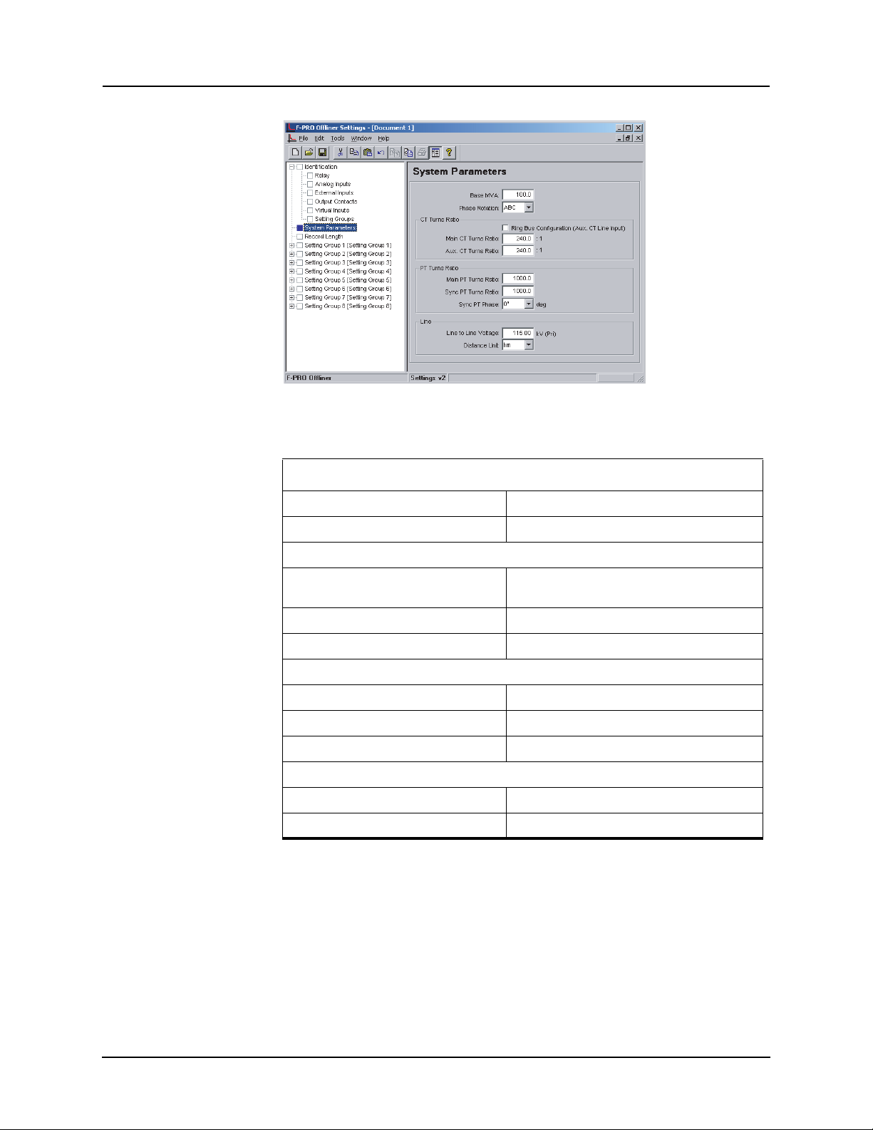
System Parameters
5 Offliner Settings Software
Figure 5.11: System Parameters
System Parameters
Base MVA 1.0 to 1000.0 MVA (primary)
Phase Rotation ABC or ACB
CT Turns Ratio
Ring Bus Configuration (Aux CT Line
Input)
Main CT Turns Ratio 1.0 to 10000.0
Aux CT Turns Ratio 1.0 to 10000.0
PT Turns Ratio
Main PT Turns Ratio 1.0 to 10000.0
Sync PT Turns Ratio 1.0 to 10000.0
Sync PT Phase 0 to 330 degrees
Line
Line to Line Voltage 1.00 to 500.00 kV (Primary)
Distance Units km or miles
Enable/disable
Base MVA
The base MVA is used for recording purposes.
D02416R04.00 F-PRO 5100 User Manual 5-11
Page 86
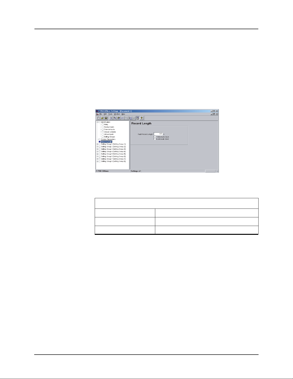
5 Offliner Settings Software
Record Length
CT Turns Ratio and PT Turns Ratio
The CT and PT ratios are specified for the analog inputs. All CT and PT ratios
are specified with a ratio relative to one (i.e. X amps to 1A). The line protection
uses the main current and the main voltage to operate. When two sets of CTs
(main and auxiliary) are used as line current input (e.g. ring bus application),
you must enable the ring bus configuration parameter to inform the relay. If enabled, the currents from the two
sets of CTs are added to the relay to form the
line current. F-PRO uses ac volts from the main PTs for its protections and for
the metering functions. A single phase voltage from the bus is connected to
sync ac volts to provide voltage for sync checking capability.
Figure 5.12: Record Length
Record Length
Fault Record Length 0.2 to 2.0 seconds
Trend Auto Save Enable/disable
Event Auto Save Enable/disable
The relay has recording and logging functions to analyze faults and to review
the operation of the overall protection scheme.
This item identifies the amount of time that e
ach fault record. Prefault is fixed
at 10 cycles.
5-12 F-PRO 5100 User Manual D02416R04.00
Page 87
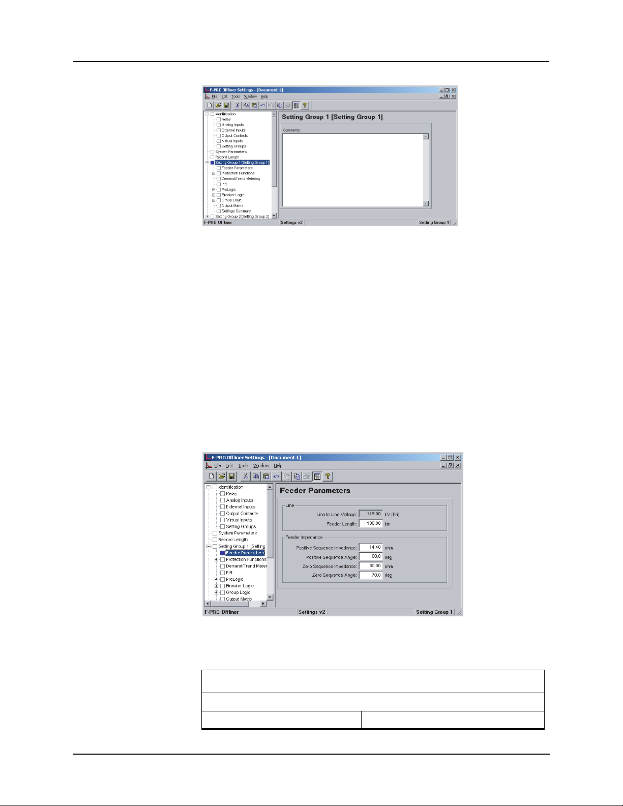
Setting Groups
5 Offliner Settings Software
Figure 5.13: Setting Groups Comments
The relay has eight setting groups (1 to 8). You can change all relay setting parameters except the physical connections su
ch as input or output parameters in
each setting group. Use any one of the 16 available Group Logic Statements
per setting group to perform Setting Group changes. The Group Logic statements are similar to the ProLogic statements with the followi
ng exceptions, the
sole function is to activate one of the eight setting groups and the processing is
in a slower half second cycle. Group Logic inputs statements can be driven
from ProLogic, any external input, previous Group Logic statements or virtual
inputs. Each Group Logic statement includes five inputs (with Boolean statements), one latch state and one pickup delay timer.
View the active setting
group from the Terminal Mode, from the front panel or from a record stored by
the relay (the active setting group is stored with the record).
Feeder Parameters
Figure 5.14: Feeder Parameters
Feeder Parameters
Line
Line to Line Voltage Fixed (from System Parameters)
D02416R04.00 F-PRO 5100 User Manual 5-13
Page 88
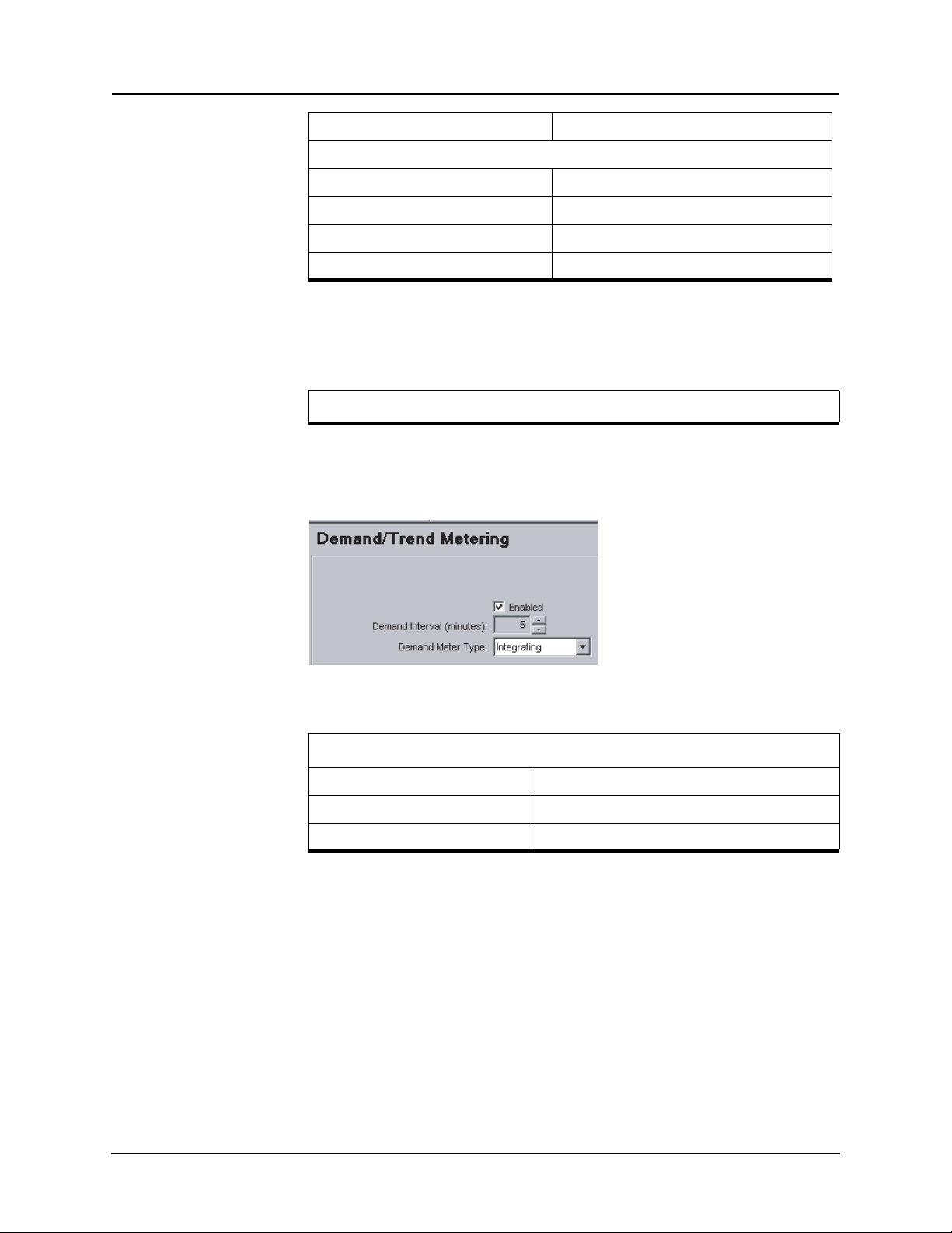
5 Offliner Settings Software
Feeder Length 1.0 to 1000.0 km or 0.62 to 621.37 miles
Feeder Impedance
Positive Sequence Impedance 0.05 to 66.00 ohms
Positive Sequence Angle 25.0 to 89.0 degrees
Zero Sequence Impedance 0.05 to 200.00 ohms
Zero Sequence Angle 25.0 to 89.0 degrees
Feeder Parameters permit a parameter entry related to the line voltage, CT ratio, PT ratio, line length, line secondary pos
itive and zero sequence impedance.
The relay internally calculates Ko from these values.
Feeder parameters are entered in secondary quantities.
Protection
Fun
ctions
Demand/Trend Metering
For detailed descriptions of the protection functions see “Protection Functions
and Specifications” on page 4-1.
Figure 5.15: Demand/Trend Metering
Demand/Trend Metering
Demand/Trend Metering Enable/disable
Demand Interval (minutes) 5 to 60 minutes with increments of 5
Demand Meter Type Integrating, rolling or thermal
5-14 F-PRO 5100 User Manual D02416R04.00
Page 89
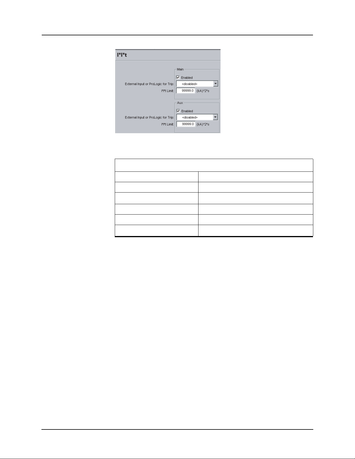
I*I*t
5 Offliner Settings Software
Figure 5.16: I*I*t
I*I*t
Main Enable/disable
External Input or ProLogic for Trip Disable or External Input or ProLogic
I*I*t Limit
0.1 to 99999.0 (KA)
2
.s
Aux Enable/disable
External Input or ProLogic for Trip Disable or External Input or ProLogic
I*I*t Limit
0.1 to 99999.0 (KA)
2
.s
D02416R04.00 F-PRO 5100 User Manual 5-15
Page 90
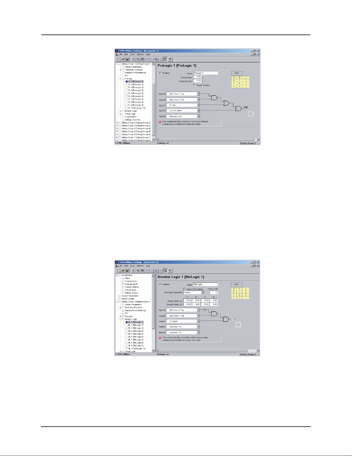
5 Offliner Settings Software
ProLogic
Figure 5.17: ProLogic
Apply ProLogic to multiple inputs to create an output based on qualified inputs. ProLogic enables up to 10 ProLogic
control statements and programs
those logics to output contacts. You can name the function being created and
set a pickup and dropout delay. Start with input A by selecting any of the relay
functions using the list for up to 5 possible inputs. Put these inputs into AND/
OR, NAND/NOR and exclusive logics and latches by clicking on the gate. Invert the input by clicking on the input line.
The output of ProLogic 1 can be nested into ProLogic 2 and so forth. If desired
you
can illuminate the front target LED on operation of this function by en-
abling this feature. The operation of the
ProLogic statements are logged on the
events listing. This logic shows on the view fault records.
Breaker Logic
Figure 5.18: Breaker Logic
5-16 F-PRO 5100 User Manual D02416R04.00
Page 91
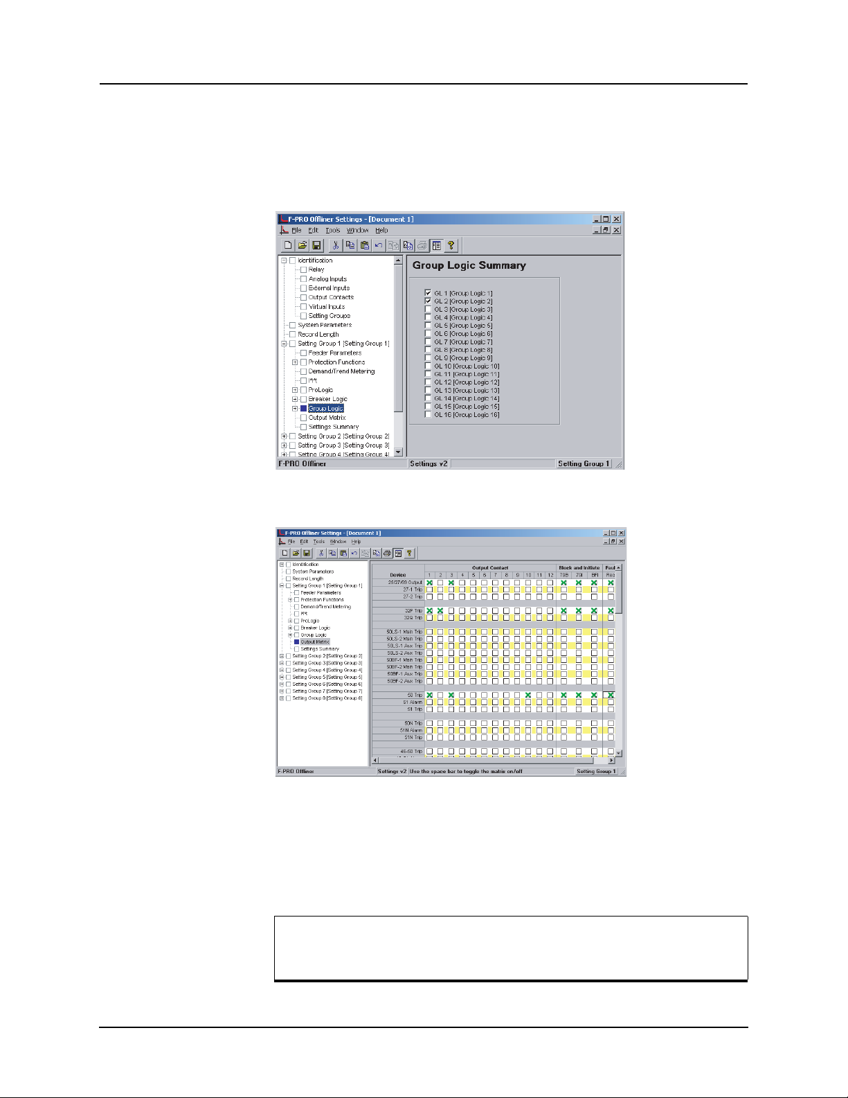
5 Offliner Settings Software
Group Logic The sixteen Group Logic statements reside in a slower processing thread with-
in the relay protection algorithms. The proc
essing cycle happens once every
half second (0.5 s). When using ProLogic statements you must keep in mind
that a latch or dropout timer should be used if the initiating condition does not
last at least 0.5 seconds.
Output Matrix
Figure 5.19: Group Logic
Figure 5.20: Output Matrix 1
The output contact matrix determines which function initiates which output relay. All output relays have a fixed 0.1 seco
nd stretch time. Functions can also
initiate fault recording, recloser blocking, recloser initiation and/or breaker
failure initiation.
For a particular function to operate correctly, it must be enabled and
must also have its logic output assigned to at least one output contact
if it is involved in a tripping function.
D02416R04.00 F-PRO 5100 User Manual 5-17
Page 92
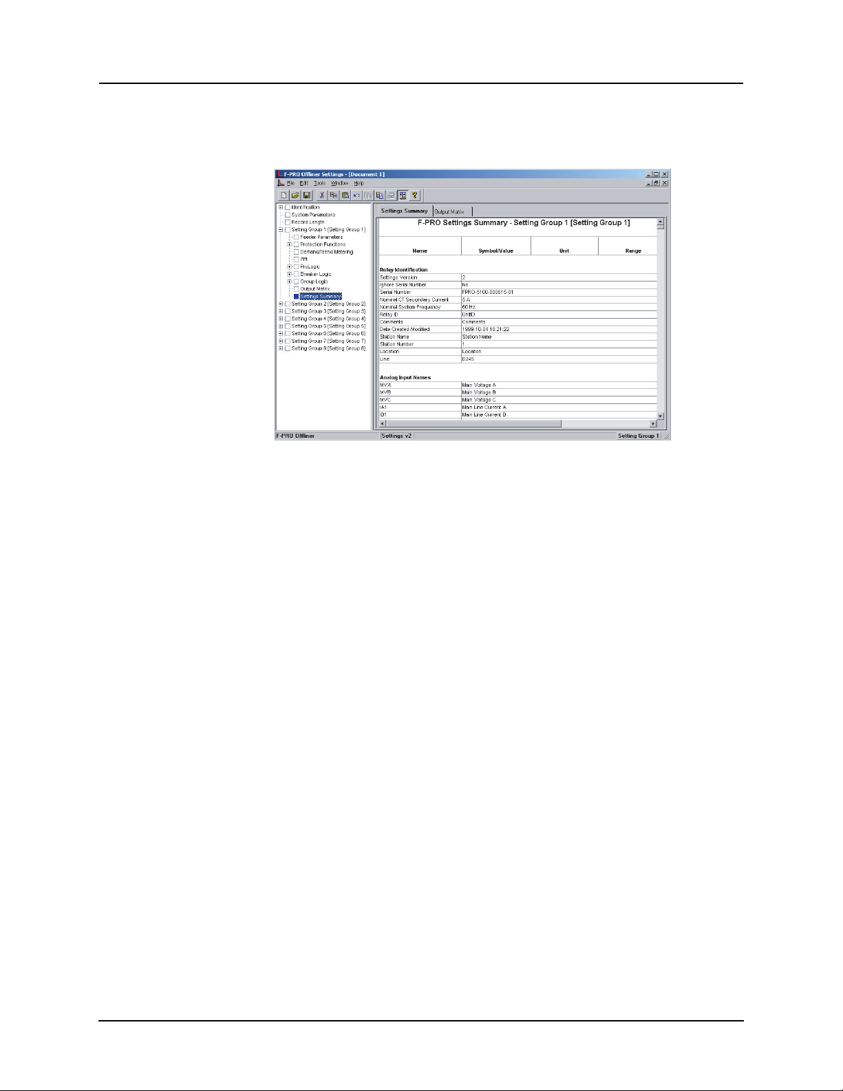
5 Offliner Settings Software
Settings Summary
Print the entire output matrix by selecting File>Print Summary. This printout
is produced on two pages.
Figure 5.21: Settings Summary
Select Settings Summary to view and print the relay settings in text form. For
details see “IED Settings and Ranges” in Appendix B.
5-18 F-PRO 5100 User Manual D02416R04.00
Page 93
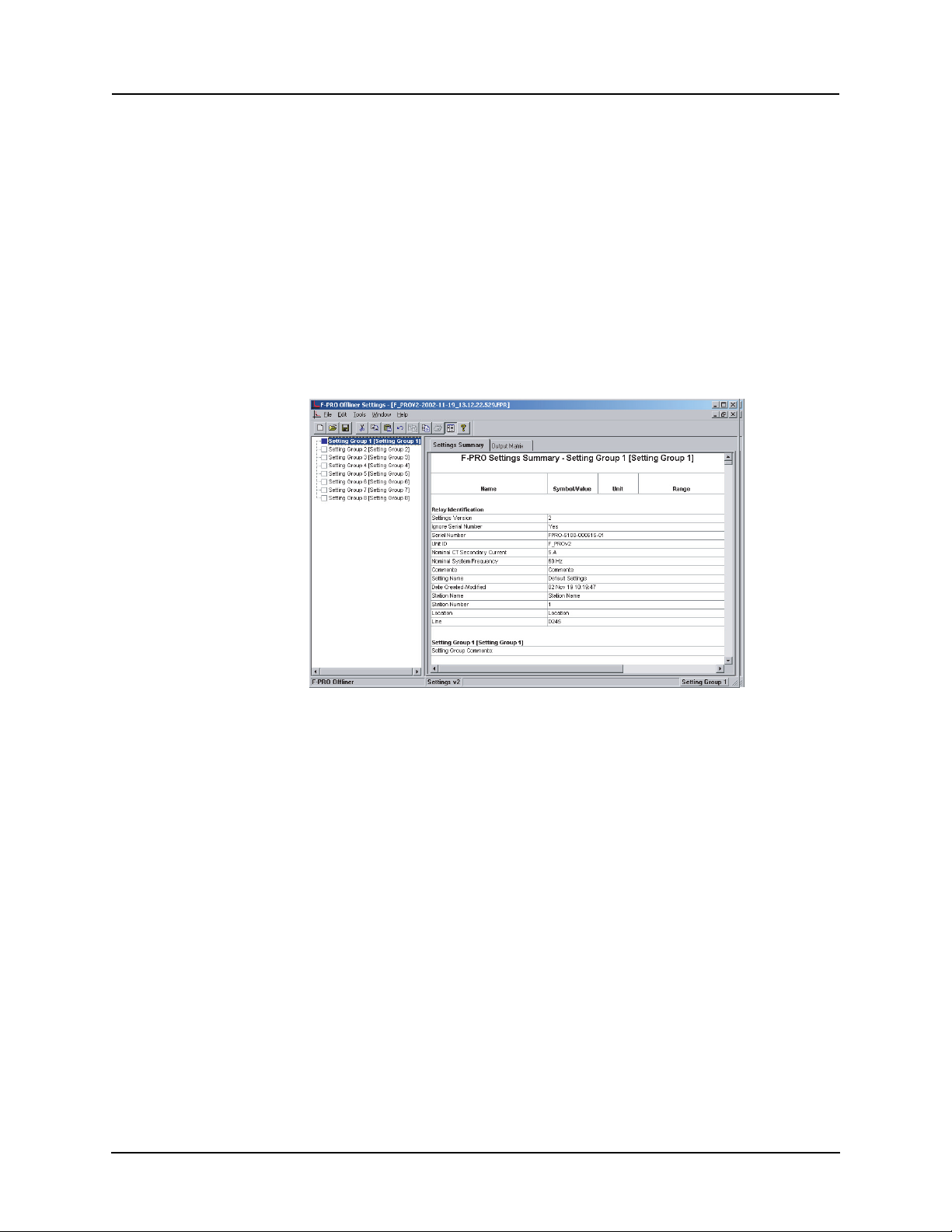
Settings From a Record
The settings on the relay at the time of a recording are included in every record
and can be viewed through the RecordBase View analysis software. While
viewing a recording in RecordBase View, select the View Setting button to display the settings. RecordBase View will
to display the settings in summary form.
If the record contains Setting Groups, the Offliner displays all Setting Groups
in the summary. Bold text in
(the Setting Group used at the time the record was captured). The setting summary is read-only. To edit the
must use File/Save As to save the summary to a file. Then close the summary
screen and open the setting file for editing.
5 Offliner Settings Software
automatically launch F-PRO Offliner
the tree view indicates an active Setting Group
setting file associated with the summary, you
Figure 5.22: View Setting Summary in RecordBase View
D02416R04.00 F-PRO 5100 User Manual 5-19
Page 94

Page 95
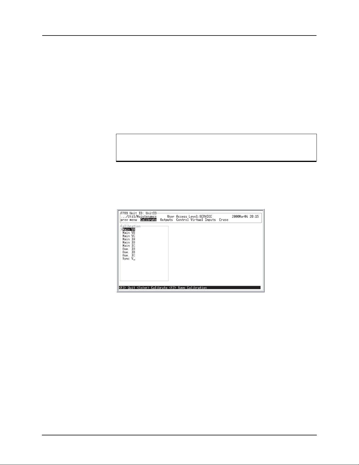
6 Testing the F-PRO Functions
Testing is required to determine if your relay performs correctly after the settings are complete or to determine verification of
cases a simple test using three voltage sources and three current sources is adequate.
relay settings needed. In most
Calibration The relay is calibrated when it
made within the relay, you may need to do a re-calibration.
Establish the accuracy of equipment used to calibrate the relay before a new calibration is attempted. A source quality of 0.5% or better
is requ
To perform a calibration, you must be logged into
at the Service access level. Select Utilities>Maintenance>Calibrate. The Calibrate menu leads you through every analog input and prompts you to apply the
a
ppropriate quantity.
ired.
leaves the factory; but if component changes are
the relay in Terminal Mode
Figure 6.1: Enter actual applied signal level
D02416R04.00 F-PRO 5100 User Manual 6-1
Page 96
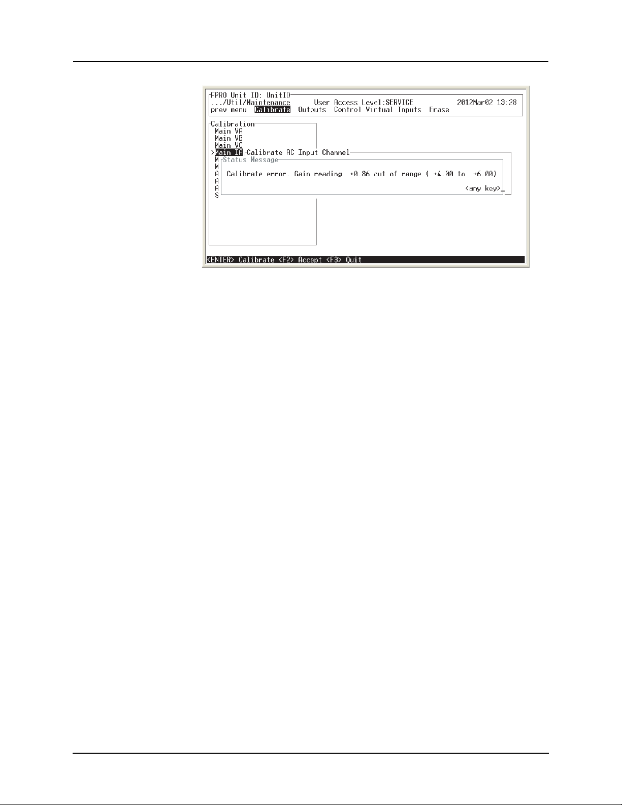
6 Testing the F-PRO Functions
Figure 6.2: Calibration error - out of range
For example, when you select voltage VA for calibration, a prompt appears
which asks you which quantity the relay should try to calibrate. If a 66 volt
phase-to-neutral quantity is applied to the back VA terminals, 66.0 volts would
be indicated as the desired calibration.
In a similar way, you are prompted to go through
all ac analog quantities and
provide the information about the injected calibration quantities. You must
have a test source to perform the function. Only the magnitude of the analog
input requires calibration, not the angle.
When an input analog channel is calibrated, verify the quantity measured by
selecting the Me
tering menu and the Analog Quantity submenu. The VA of the
ac voltage input is used as a reference quantity by your relay. Therefore, if it is
absent, there is not a locked, valid relationship among all of the analog quantities.
Testing the External
uts
Inp
To test the external inputs, the relay is connected to a laptop in the Terminal
Mode, in service level, in the I/O sub-menu. This screen displays the status of
the Event Input and the Output Contacts. Placing a voltage of 125 Vdc nom.
(150 V maximum) to each of the external inputs in turns causes the input to
change from Low to High status. These inputs are polarity sensitive. This
screen has a 0.5 second update rate.
Testing the Output
Contacts
Relay
The output relays are tested to verify their integrity using the terminal mode
Utilities menu and the Output Contacts sub-menu. At this stage the output contacts can be closed by pressing Enter key.
This toggles the output contact from
Open to Closed. Pressing the Enter key again toggles the contact status to Open
again. The output contact status is verified using an ohmmeter. When you exit
this sub-menu, all contact status reverts to the open position.
6-2 F-PRO 5100 User Manual D02416R04.00
Page 97

7 Installation
Physical Mounting
Standard 3U The relay is 3 rack units or 5.25 inches high and approximately 12.25 inches
deep. The standard relay is designed for a 19-inch rack. A complete mechani
cal drawing is shown, for details see “Mechanical Drawings” in Appendix G.
To install the relay you need the following:
• 19 inch rack
• 4 - #10 screws
AC and DC Wiring
For details see “AC Schematic Drawing” in Appendix I and “DC Schematic
Drawing” in Appendix J.
Communication Wiring
EIA-232 All of the relay’s serial ports (Ports 1, 2 and 3) are configured as EIA RS-232
Data Communications Equipment (DCE) devices with female DB9 connec
tors. This allows them to be connected directly to a PC serial port with a standard straight-through male-to-female serial cable for pin-out, for details see
“Communication Port Details” on page 2-9.
-
-
Ethernet/Modem The relay has an RJ-45 receptacle for accepting a 10BaseT Ethernet connector
or an RJ-11 connector.
IRIG-B Wiring The IRIG-B connector on the back of the relay is BNC type.
D02416R04.00 F-PRO 5100 User Manual 7-1
Page 98

Page 99

8 Cyber Security
System Access Control and Authorisation
Access to B-PRO is protected by login name and password. Each login name
is associated with an Access Level. Section 3 “Terminal Mode” provides de
tails on the Access Levels and login names.
-
Password Complexity
Password maximum length is 22 characters. Password may contain:
• Lower case letters ( a – z )
• Upper case letters ( A – Z )
• Numeric characters ( 0 – 9 )
• Special characters as follows:
Table 8.1: Special Characters
Character ASCII Decimal Description
! 033 Exclamation mark
“ 034 Quotation mark
# 035 Number sign
$ 036 Dollar sign
% 037 Percent sign
& 038 Ampersand
‘ 039 Apostrophe
( 040 Left parenthesis
) 041 Right parenthesis
* 042 Asterisk
+ 043 Plus sign
, 044 Comma
- 045 Hyphen-minus
. 046 Full stop
/ 047 Slash (Solidus)
: 058 Colon
; 059 Semicolon
< 060 Less-than sign
= 061 Equal sign
> 062 Greater-than sign
? 063 Question mark
D02416R04.00 F-PRO 5100 User Manual 8-1
Page 100
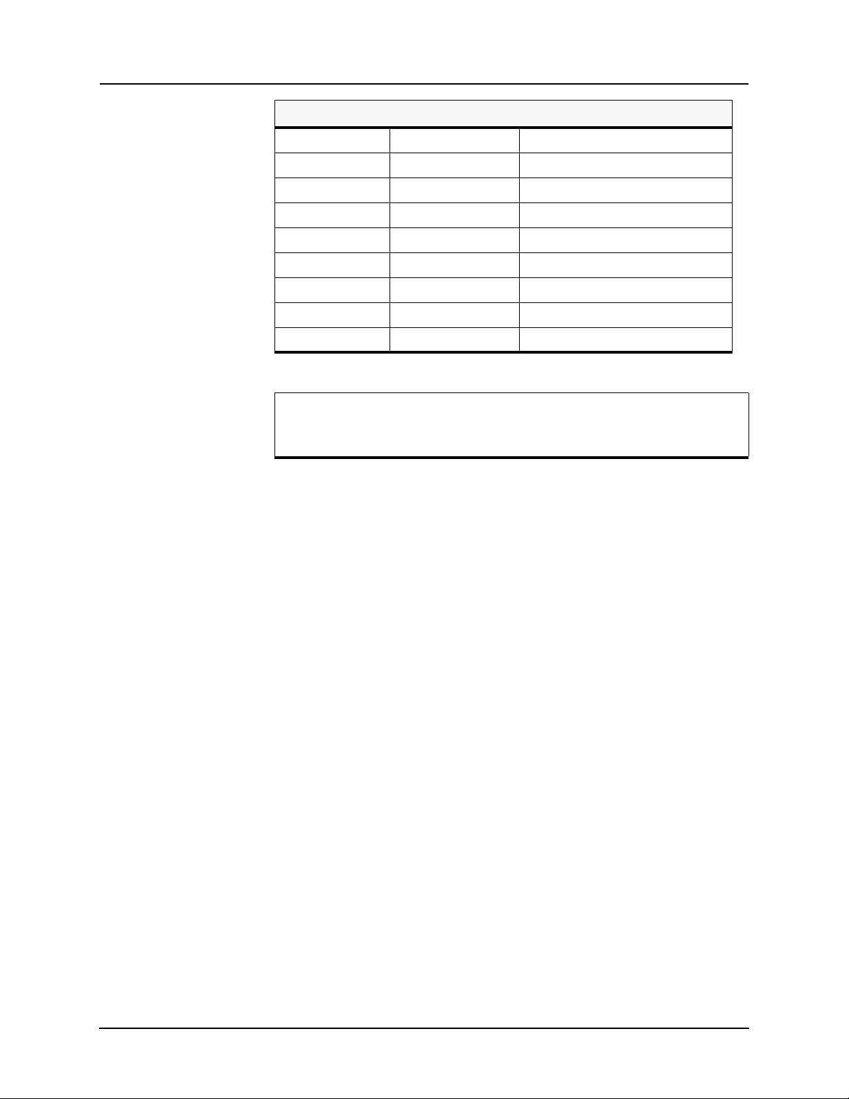
8 Cyber Security
Table 8.1: Special Characters
@ 064 At sign
[ 091 Left Square Bracket
] 093 Right Square Bracket
^ 094 Circumflex accent
_ 095 Low line
| 124 Vertical bar
{ 123 Left Curly Bracket
} 125 Right Curly Bracket
~ 126 Tilde
Special characters other than listed above may currently be used for
passwords. However, only the listed characters are guaranteed to be
supported in the future.
B-PRO does not inforce password complexity rules. However, password compliance to the following comp
lexity rules can be verified, when password is be-
ing updated
• Minimum password length 8 characters.
• At least one upper case character.
• At least one lower case character.
• At least one numerical character.
• At least one special character.
Access Timeout User is automatically logged out after 60 mi
Access Level
Block
ing
B-PRO automatically blocks (locks out) Access Level for 5 minutes after 7 unsuccessful login attempts. Lock-out of one
ability of the others.
Authorization by
Acce
ss Level
Each Access Level is assigned a set of functions authorized for it. The set of
functions is pre-defined and cannot be changed. Six Access Levels are defined.
Access Level list and set of functions associated with each level are described
in section 3 “Terminal Mode”.
nutes of inactivity.
Access Level does not affect avail-
8-2 F-PRO 5100 User Manual D02416R04.00
 Loading...