

Page 1

B-PRO
www . ElectricalPartManuals . com
Bus Protection Relay
Model 8700/BUS
User Manual
Version 2.1 Rev 2
Page 2

www . ElectricalPartManuals . com
Page 3

Preface
www . ElectricalPartManuals . com
Information in this document is subject to change without notice.
© 2008 ERLPhase Power Technologies Ltd. All rights reserved.
Reproduction in any manner whatsoever without the
ERLPhase Power Technologies Ltd. is strictly forbidden.
This manual is part of a complete set of p
detailed drawings and operation. Users should evaluate the information in the
context of the complete set of product documentation and their particular
applications. ERLPhase assumes no liability for any incidental, indirect, or
consequential damages arising from the use of this documentation.
While all information presented is believe
with accepted engineering practices, ERLPhase makes no warranties as to the
completeness of the information.
All trademarks used in association with B-PRO,
T-PRO, TESLA, TESLA Control Panel, RecordGraph and RecordBase are
trademarks of ERLPhase Power Technologies Ltd.
Windows
Procomm
HyperTerminal
Modbus
®
is a registered trademark of the Microsoft Corporation.
®
is a registered trademark of Symantec.
®
is a registered trademark of Hilgraeve.
®
is a registered trademark of Modicon.
roduct documentation that includes
d to be reliable and in accordance
written permission of
F-PRO, L-PRO, ProLogic,
Contact Information
ERLPhase Power Technologies Ltd.
Website: www.erlphase.com
Email: [email protected]
Technical Support
Email: [email protected]
Tel: 204-477-0591
D01908R02.12 B-PRO User Manual 8700 i
Page 4

Preface
www . ElectricalPartManuals . com
ii B-PRO User Manual 8700 D01908R02.12
Page 5
Version Compatibility and Release History
www . ElectricalPartManuals . com
This chart indicates the versions of Offliner Settings, RecordBase View and the
User Manual which are compatible with different versions of B-PRO firmware.
RecordBase View and Of
lier versions of records and setting files. You can
records produced by any version of B-PRO firmware and Offliner Settings can
create and edit older setting file versions.
Minor releases (designated with a letter suffix
compatibility as their base version. For example. B-PRO firmware v1.1b and
Offliner Settings v1.1a are compatible.
B-PRO 8700/BUS Firmware/Software Compatibility Guide
fliner Settings are backward compatible with all ear-
use RecordBase View to view
- e.g. v1.1a) maintain the same
B-PRO
Firmware
v2.1a 9 4 v2.1 or greater v1.5d or greater
v2.1 9 4 v2.1 or greater v1.5d or greater
v2.0 9 3 v2.0 or greater v1.5d or greater
v1.1 9 2 v1.1 or greater v1.4 or greater
v1.0 8 1 v1.0 or greater v1.1 or greater
B-PRO 8700/BUS Firmware Revision History
Date
2007 Mar 14 v2.1a Improved 87B security
2006 Jun 29 v2.1 Improved 87T target on wye-connected transformers
Record
Version
Version
Setting
Version
Changes from Previous Version
Separated MVA settings for Bus 1 and Bus 2
Added invert switch on each digital control
Extended transformer MVA setting range
Increased external input glitch filter
Added support for a backup DNP SCADA Master
Compatible
Offliner Settings
Compatible
RecordBase View
security
2004 Jul 30 v2.0 Added multi bus differential zones (87B-1 and 87B-2).
Added 30 virtual inputs for SCADA controls.
Added swing recording.
Added IO and IR recording to 87T.
Extended Bus MVA setting range.
2004 May 5 v1.1c Corrected SCADA protocol errors
2004 Mar 24 v1.1b Improved the Self Check algorithm to detect DC offset faster.
D01908R02.12 B-PRO User Manual 8700 iii
Fixed reporting of time synchronization status in records.
Fixed handling of user-specified IP addr
zeros.
esses with leading
Page 6
Version Compatibility and Release History
www . ElectricalPartManuals . com
B-PRO 8700/BUS Firmware Revision History
2003 Jan 17 v1.1a PT Turns Ratio on the System Parameters screen expanded
2002 Aug 08 v1.1 Add CT saturation detector.
2001 Mar 07 v1.0 First release.
to allow a setting up to 10000:1.
Standardized 51 IEEE parameters, user-defined directional
racteristics.
cha
Increased 81 sensitivity for minimum time delay.
B-PRO 8700/BUS Offliner Settings Revision History
Date
2006 Jun 29 v2.1 Separated MVA settings for Bus 1 and Bus 2
2004 Jul 30 v2.0 Added multi bus differential zones (87B-1 and 87B-2).
2003 Jan 17 v1.1b PT Turns Ratio on the System Parameters screen expanded
Offliner
ings
Sett
Version
Changes from Previous Version
Added invert switch on each digital control
Extended transformer MVA setting range
Added 30 virtual inputs for SCADA.
Added swing recording capability.
Extended Bus MVA setting range.
a setting up to 10000:1.
to allow
2002 Sep 18 v1.1a Correct an error in ProLogic input list.
2002 Aug 12 v1.1 Add CT saturation detector.
2001 Mar 07 v1.0 First release.
Standardized 51 IEEE parameters, user-defined directional
racteristics.
cha
B-PRO 8700/BUS User Manual Revision History
Date Manual
Ver si on
2008 Feb 29 v2.1 Rev 2 Branded to ERLPhase.
2007 Mar 14 v2.1 Rev 1 Update to include firmware v2.1a support
2006 Jun 29 v2.1 Update to include firmware v2.1 support
2004 Jul 30 v2.0 Rev 1 Update to include firmware v2.0 support
2004 May 5 v1.1 Rev 5 Minor consistency improvements
2004 Mar 24 v1.1 Rev 4 Update to include firmware v1.1b support.
2003 Oct 31 v1.1 Rev 3 Updated format of manual.
Changes from Previous Version
iv B-PRO User Manual 8700 D01908R02.12
Page 7

Version Compatibility and Release History
www . ElectricalPartManuals . com
B-PRO 8700/BUS User Manual Revision History
2003 Jan 17 v1.1 Rev 2 PT Turns Ratio on the System Parameters screen expanded
2002 Aug 12 v1.1 Update to include new functions.
2001 Aug 14 v1.0 Rev 2 Update Setup and Communications.
2001 Mar 07 v1.0 First release.
to allow a setting up to 10000:1.
D01908R02.12 B-PRO User Manual 8700 v
Page 8

www . ElectricalPartManuals . com
Page 9
Using This Guide
www . ElectricalPartManuals . com
This user manual describes the installation and operation of the B-PRO bus
protection relay user interface software. It is intended to support the first time
user and clarify the details of the equipment.
The manual uses a number of conventions to denote special information:
Example Describes
Start>Settings>Control Panel Choose the Control Panel submenu in the Set-
Right-click Click the right mouse button.
Recordings Menu items and tabs are shown in italics.
tings submenu on the Start menu.
service User input or keystrokes are shown
Text boxes similar to this one Relates important notes and information.
.. Indicates more screens.
Indicates further drop-down menu, click to display list.
Indicates a warning.
in bold.
D01908R02.12 B-PRO User Manual 8700 vii
Page 10

www . ElectricalPartManuals . com
Page 11

Table of Contents
www . ElectricalPartManuals . com
Preface ......................................................................................i
Contact Information ...................................................................i
Version Compatibility and Release
History.............................. iii
Using This Guide .................................................................... vii
Table of Contents .....................................................................1
1 Overview ................................................................. 1-1
Front View .............................................................................................1-3
Back View.............................................................................................. 1-4
Model Options/Ordering ........................................................................1-5
2 Setup and Communications.................................. 2-1
Power Supply ........................................................................................2-1
IRIG-B Time Input.................................................................................. 2-1
Communicating with the Relay (IED)..........
Using HyperTerminal to Access the Relay’s User I
Setting the Baud Rate ...........................................................................
Accessing the SCADA Services.................
Communication Port Details.......................
Maintenance Menu..............................................................................2-11
Firmware Update................................................................................. 2-12
...........................................2-2
nterface.................. 2-5
2-6
...........................................2-7
...........................................2-8
3 Using the IED (Getting Started) ............................ 3-1
Start-up Sequence ................................................................................ 3-1
Front Panel Display ...............................................................................3-2
Terminal Mode.......................................................................................3-4
Metering Data...................................................................................... 3-14
4 Protection Functions ............................................. 4-1
Differential Zone Selection and CT Input Assignment...........................4-1
Digital Control........................................................................................ 4-1
Protection Function Descriptions........................................................... 4-1
Recording Functions............................................................................ 4-21
Event Log ............................................................................................4-24
5 Offliner Settings Software..................................... 5-1
Introduction............................................................................................ 5-1
Installing PC Software ...........................................................................
Offliner Features....................................................................................5-2
Main Branches from the Tree View .......................................................5-7
Offliner Keyboard Shortcuts ..................................................................5-9
Handling Backward Compatibility ...............
.........................................5-10
5-2
D01908R02.12 B-PRO User Manual 8700 i
Page 12

Table of Contents
www . ElectricalPartManuals . com
RecordBase View Software.................................................................5-12
6 Testing the B-PRO Functions ............................... 6-1
7 Installation .............................................................. 7-1
Physical Mounting ................................................................................. 7-1
AC and DC Wiring .................................................................................
Communication Wiring ..........................................................................7-1
Appendix A IED Specifications .............................................A-1
Appendix B IED Settings and Ranges..................................B-1
Appendix C Hardware Description .......................................C-1
Appendix D Event Messages ...............................................D-1
Appendix E Modbus RTU Communication Protocol.............E-1
Appendix F DNP3 Communication Protocol......................... F-1
Appendix G Mechanical Drawings........................................G-1
Appendix H Rear Panel Drawings ........................................H-1
Appendix I AC Schematic Drawing........................................ I-1
7-1
Appendix J DC Schematic Drawing.......................................J-1
Appendix K Bus Differential Function Setting Examples ...... K-1
Appendix L Function Logic Diagram..................................... L-1
Appendix M Analog Phase Shift Table ................................ M-1
Appendix N How to Start the CT Saturation Calculator........N-1
Index..........................................................................................I
Software Installation Instructions.............................................III
ii B-PRO User Manual 8700 D01908R02.12
Page 13
1 Overview
www . ElectricalPartManuals . com
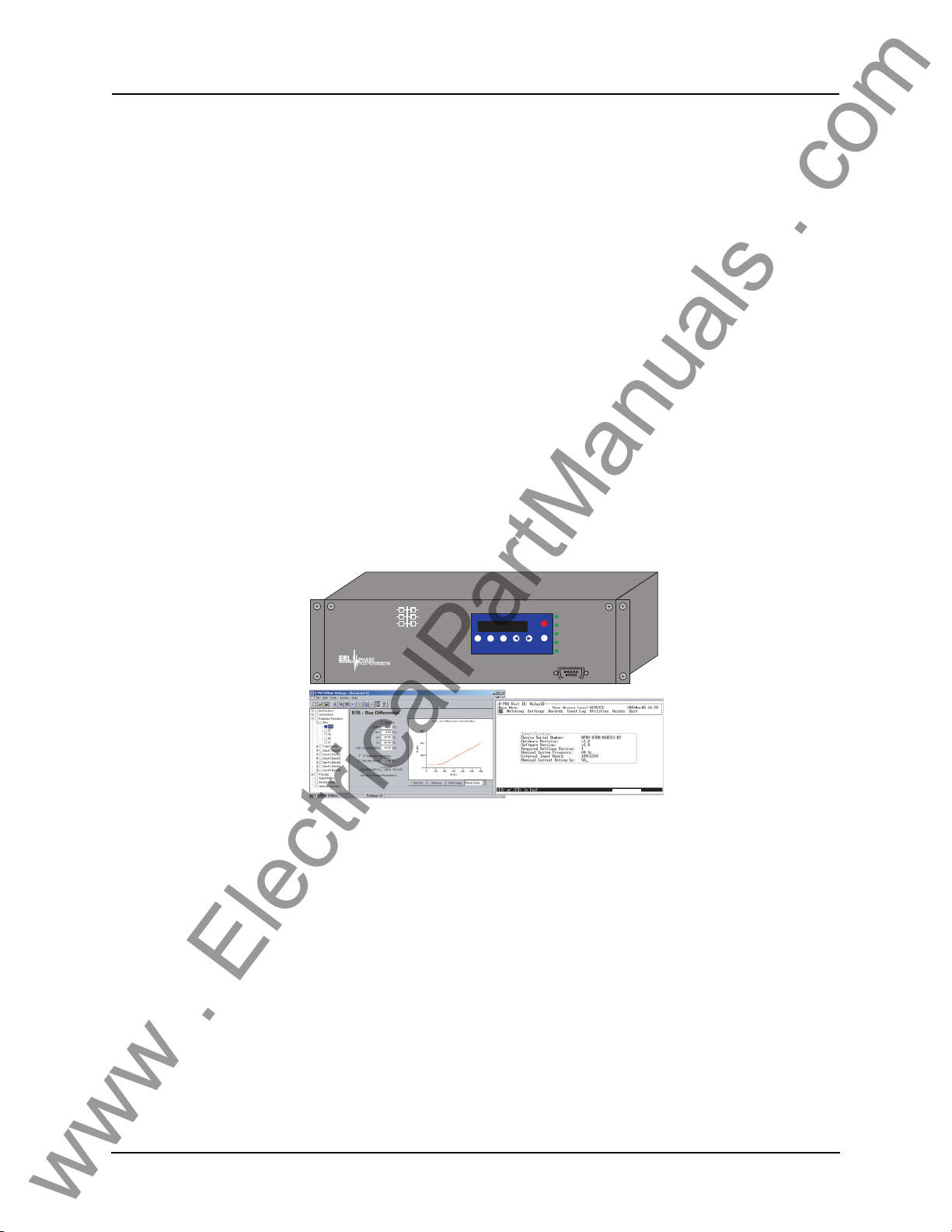
The B-PRO (model 8700/BUS) is a microprocessor-based relay providing bus
differential protection, integrated breaker failure and overcurrent protection
functions, metering, fault and swing oscillography.
B-PRO has two working modes—online and offline. In the online mode you
can us
e any communication software package (e.g. Procomm or HyperTermi-
nal) to connect to the B-PRO using VT100 terminal emulat
ion. In online mode
you can:
• change and review relay
settings
• view event and metering information
• initiate and retrieve recordings, and retrieve setti
In offline mode you can use Offliner Se
ttings and RecordBase View software
ngs
to:
• create and review relay settings
• analyze fault waveforms
• store records
B-PRO Bus Protection Relay
B-PRO
BUS PROTECTION RELAY
MODEL 8700/BUS
Offline Mode - Settings Software
2000 JAN 07
View
View
Prev
Date &
Readings
Logs
Time
B
The B-PRO relay provides differential prote
RELAY FUNCTIONAL
IRIG-B FUNCTIONAL
Target
SERVICE REQUIRED
TEST MODE
Next
Clear
Target
ALARM
PORT 1
Online Mode -Terminal Mode
2000Dec14
ction (low-impedance) for the fol-
lowing types of bus configurations:
• 1 bus with up to six inputs and one set
of voltage inputs (Figure ).
• 1 transformer zone with 2 inputs.
• 2 differential zones, 1 for a bus and 1
for a transformer (Figure ).
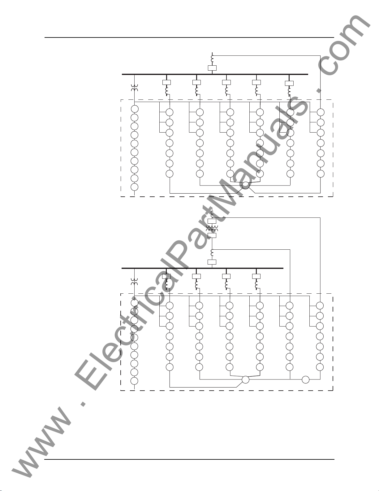
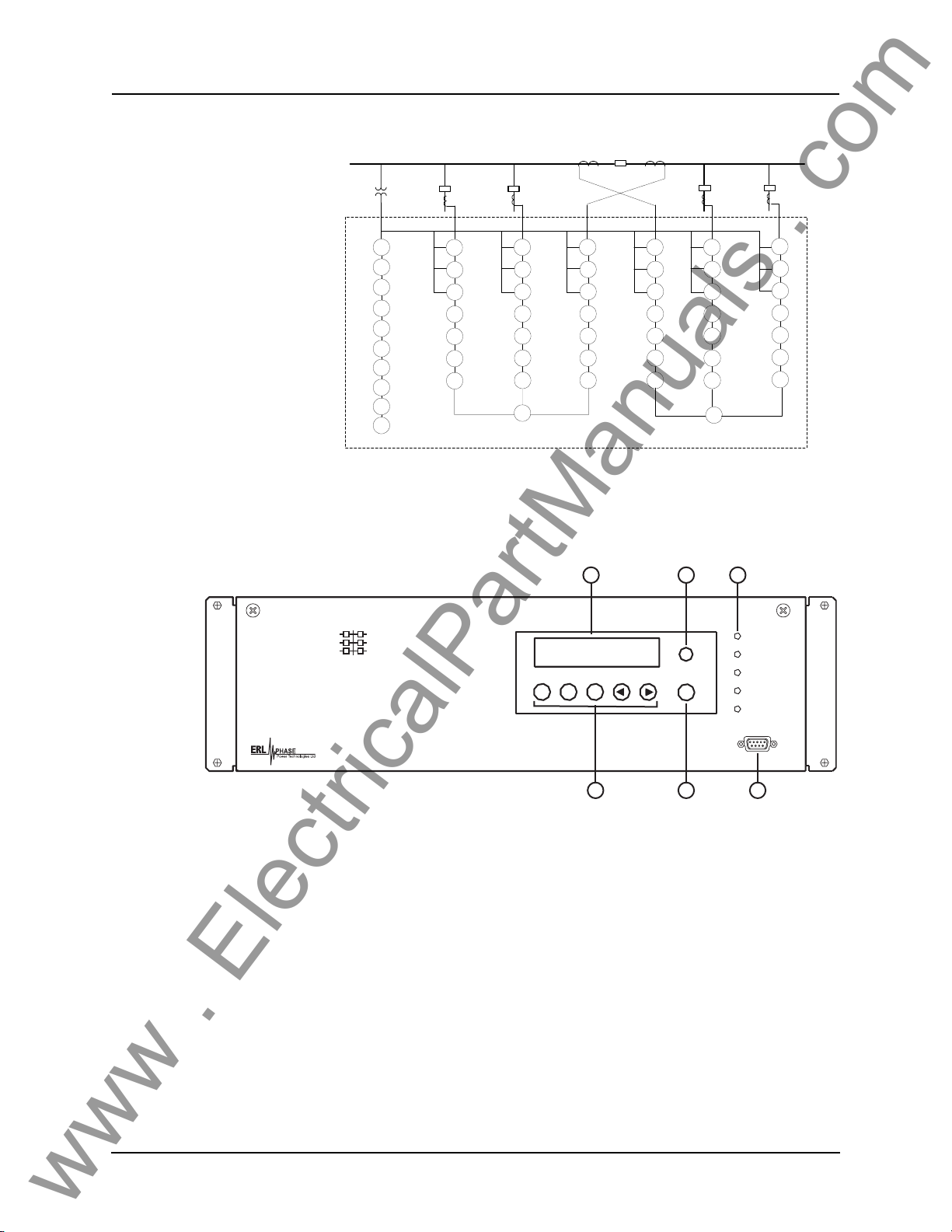
• 2 bus zones (Figure 1.3).
Backup feeder protection is provided for all inputs, regardless of which z
selected, even if an input is not used in a differential zone.
one is
D01908R02.12 B-PRO User Manual 8700 1-1
Page 14
1 Overview
www . ElectricalPartManuals . com
50/51
/67
50N/51N
/67
46-50/
46-51/
67
50BF
50LS
-1
50LS
-2
Rec
52
52525252
50/51
/67
50N/51N
46-50/
46-51/
67
50BF
50LS
50LS
Rec
/67
-1
-2
87B
B-PRO
50/51
50N/51N
46-50/
46-51/
50BF
50LS
50LS
Bus
PT
27-1
27-2
59-1
59-2
81O-1
81O
81U
81U
Rec
60
-2
-1
-2
50/51
/67
50N/51N
46-50/
46-51/
50BF
50LS
50LS
Rec
/67
67
-1
-2
Figure 1.1: B-PRO Function Diagram (1 differential zone)
52
Transformer
52
52
/67
/67
67
-1
-2
Rec
50/51
/67
50N/51N
46-50/
46-51/
67
50BF
50LS
50LS
Rec
/67
-1
-2
50/51
/67
50N/51N
/67
46-50/
46-51/
67
50BF
50LS
-1
50LS
-2
Rec
50/51
/67
50N/51N
/67
46-50/
46-51/
67
50BF
50LS
50LS
Rec
52
52525252
50/51
/67
50N/51N
/67
46-50/
46-51/
67
50BF
-1
-2
50LS
50LS
Rec
-1
-2
87B
B-PRO
50/51
/67
50N/51N
/67
46-50/
46-51/
67
50BF
50LS
50LS
Rec
50/51
/67
50N/51N
/67
46-50/
46-51/
67
50BF
-1
-2
50LS
50LS
Rec
-1
-2
50/51
/67
50N/51N
/67
46-50/
46-51/
67
50BF
50LS
-1
50LS
-2
Rec
87T
Bus
PT
27-2
59-1
59-2
27-1
81O
81O
81U
81U
Rec
60
-1
-2
-1
-2
50/51
50N/51N
46-50/
46-51/
50BF
50LS
50LS
Rec
/67
/67
67
-1
-2
Figure 1.2: B-PRO Function Diagram (2 differential zones, 1 Bus & 1 Transformer)
1-2 B-PRO User Manual 8700 D01908R02.12
Page 15
1 Overview
www . ElectricalPartManuals . com
Front View
67
50/51
67
50N/
51N
67
50/51/
46
50BF
50LS
-1
50LS
-2
Rec
B-PRO
52
52
67
50/51
67
50N/
51N
67
50/51/
46
50BF
50LS
-1
50LS
-2
Rec
67
50/51
67
50N/
51N
67
50/51/
46
50BF
50LS
-1
50LS
-2
Rec
87B
-2
Bus1
PT
27-1
27-2
59-1
59-2
60
81-O-
1
81-O-
2
81-U-
1
81-U-
2
Rec
67
50/51
67
50N/
51N
67
50/51/
46
50BF
50LS
-1
50LS
-2
Rec
5252
67
50/51
67
50N/
51N
67
50/51/
46
50BF
50LS
-1
50LS
-2
Rec
87B
-1
Figure 1.3: B-PRO Function Diagram (2 differential zones: Bus1 and Bus2)
1 2 3
Bus2
52
67
50/51
67
50N/
51N
67
50/51/
46
50BF
50LS
-1
50LS
-2
Rec
B-PRO
Bus Protection Relay
Model 8700/BUS
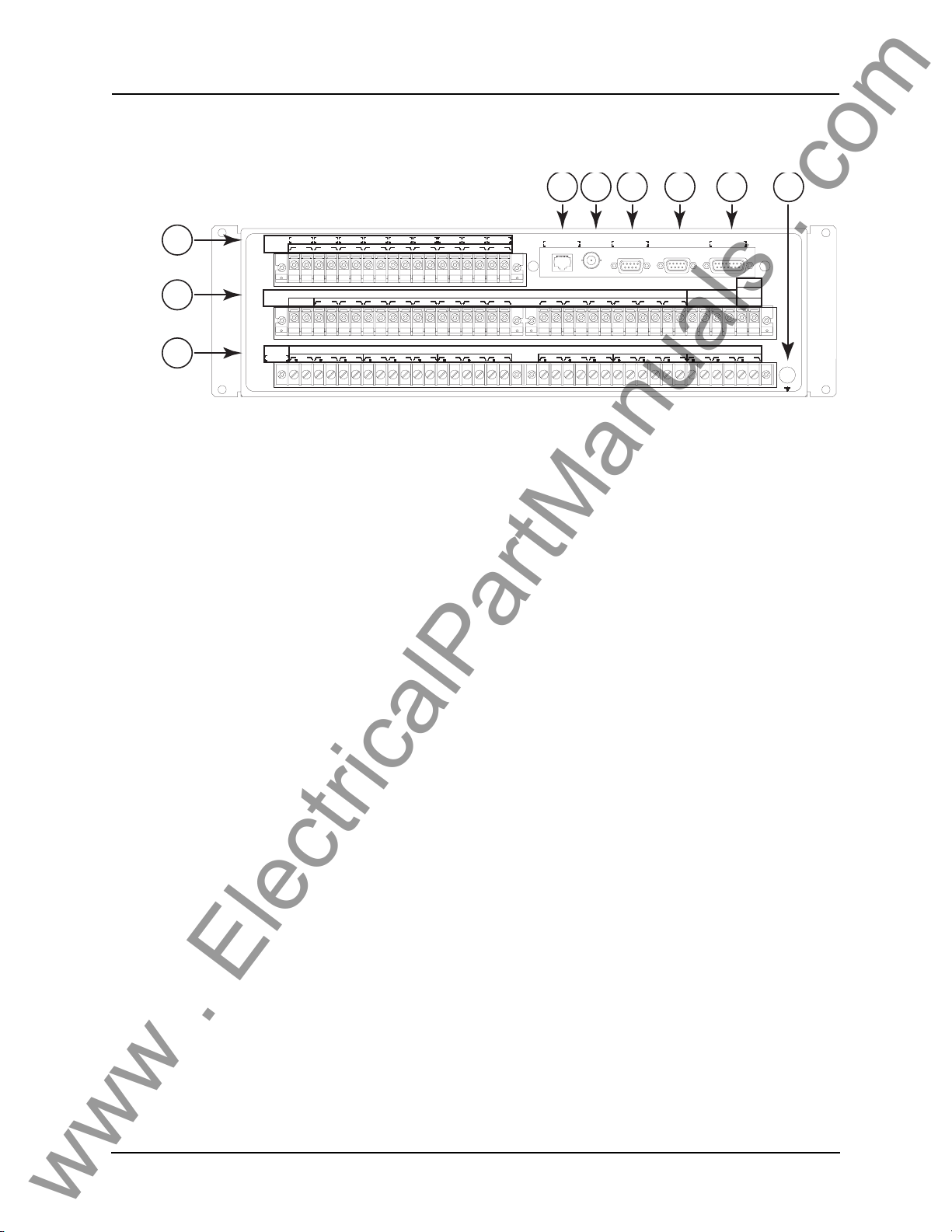
1. Front display of time, alarms, and relay target
2. Relay target LED (red)
3. LEDs indicating status of relay
4. Communications serial port 1 for laptop computer
5. Clear target push button
6. Push buttons to manipulate information on LCD display
Figure 1.4: B-PRO Front View
Date &
Time
View
Readings
View
Logs
6
Previous Next
Target
Clear
Target
5 4
Relay Functional
IRIG-B Functional
Service Required
Test Mode
Alarm
Port 1
D01908R02.12 B-PRO User Manual 8700 1-3
Page 16
1 Overview
www . ElectricalPartManuals . com
Back View
13
14
15
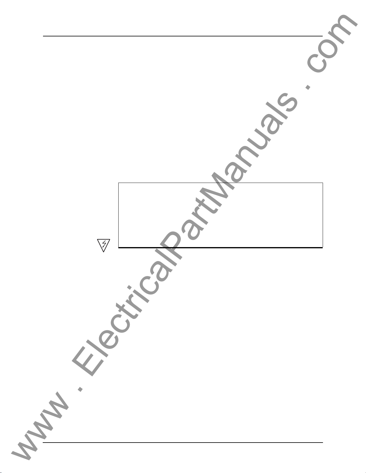
7. Port 5 - 10BaseT Ethernet Port/Internal Modem (optional)
8. External clock, IRIG-B modulated or unmodulated
9. Port 2 - Direct/Modem RS-232 Port
10. Port 3 - SCADA
11. Port 4 - unused
12. Case ground
13. 9 programmable inputs
14. This row contains 4 distinct areas from left to right:
- Relay Inoperative contact
- 14 programmable output contacts
- 3 ac voltage inputs
- power supply
15. 18 ac current inputs
Inputs
Output
Contacts
In, Freq.
5A, 60Hz
2
1
+ -
+ -3+ -4+ -5+ -6+ -7+ -8+ -9+ -
102 103 104 105 106 107 108 109 110 111 112 113 114 115 116 117
100 101
Relay
Inoperative
300 301 302 303 304 305 306 307 308 309 310 311 312 313 314 315 316 317 335334333332331330329328327326325324323322321320319318
Out 2 Out 3 Out 4 Out 5 Out 6 Out 7 Out 8
Out 1
125VDC 125VDC 125VDC 125VDC 125VDC 125VDC 125VDC 125VDC
125VDC
External
Figure 1.5: B-PRO Back View
7 8 9 10 11 12
PORT 2
IRIG-BPORT 5 PORT 4
Unused Direct / Modem Unused
Out 9
217216215214213212211210209208207206205204203202201200 218 219 220 221 222 223 224 225 226 227 228 229 230 231 232 233 234 235
AC Current Inputs
I4 A I4 B I4 C I5 CI5 BI5 AI3 A I3 B I3 CI2 A I2 B I2 CI1 CI1 BI1 A
PORT 3
SCADA
Power
Supply
Nominal
48 - 250 Vdc
AC Volts
Out 14Out 13Out 12Out 11Out 10
120 Vac
NVCVBVA
+-
I6 CI6 BI6 A
Case Gnd
AC Current and Voltage Inputs
B-PRO is provided with terminal blocks for up to 18 ac currents and 3 phase
to neutral voltages.
Each of the current input circuits has polarity
A complete schematic of current and voltage
(•) marks.
circuits is shown, for details see
“AC Schematic Drawing” in Appendix I and “DC Schematic Drawing”
in Appendix J.
External Inputs The B-PRO relay contains 9 programmable external inputs. External dc volt-
age of either 48/125 volts or 125/250 volts no
minal are possible depending on
the range provided.
To prevent an external input from picking up on spurious voltage pulses, a software filter is applied to the input signals. The filter ignores logi
c high voltage
levels that occur for less than 2 milliseconds. This was increased from 700 mi-
Output Relay
acts
Cont
croseconds in firmware version
The B-PRO relay has 14 output relay contacts. Each contact is programmable
and has breaker tripping capability. All output contacts are isolated from each
2.1.
other. The output contacts are closed for a minimum of 100 ms after operation.
Relay Inoperative Alarm Output
If the relay is in self check program or becomes inoperative,
operative Alarm output contact closes and all
tripping functions are blocked.
then the Relay In-
1-4 B-PRO User Manual 8700 D01908R02.12
Page 17

Model Options/Ordering
www . ElectricalPartManuals . com
B-PRO is available as a horizontal mount, for details see “Mechanical Drawings” in Appendix G.
B-PRO is available with an internal modem card or internal
The CT inputs are 1 A nominal or 5 A nominal. The external inputs
Vdc or 125/250 Vdc. The system base frequency is either 50 Hz or 60 Hz.
All of the above options must be spec
1 Overview
network card.
are 48/125
ified at the time of ordering.
D01908R02.12 B-PRO User Manual 8700 1-5
Page 18

www . ElectricalPartManuals . com
Page 19
2 Setup and Communications
www . ElectricalPartManuals . com
Power Supply
A wide range power supply is standard. The nominal operating range is 48 to
250 Vdc, 120 Vac, 50/60 Hz. To protect against a possible short circuit in the
supply use an inline fuse or circuit breaker with a 5 A rating. Make the chassis
ground connection to ensure proper operation and safety.
There are no power switches on the relay. When the
ed, the relay starts its initialization process and takes about
plete showing the green Relay Functional LED.
power supply is connect-
40 seconds to com-
Case Grounding You must ground the relay to the station gro
minal at the back of the relay, for details see for details see Figure 1.4: B-PRO
Front View on page 1-3.
WARNING!
To ensure safety and proper operation you must connect the relay to
station ground using the rear grounding terminal on the relay.
the
Ground the relay even when testing.
Do not rely on the rack mounting screws to provide case grounding.
IRIG-B Time Input
The relay is equipped to handle modulated or unmodulated GPS satellite time
IRIG-B signals. The IRIG-B time signal is connected to the BNC connection
on the back of the relay. When the IRIG-B signal is provided to the relay and
is enabled in the settings through the user interface, the IRIG-B functional LED
comes on and the relay clock is referenced to this signal. No settings are required to differentiate between modulated or unmodulated signals; this is automatically detected by the relay.
You can enable or disable the IEEE 1344
tings Utiliti
IRIG-B signal. Disable this setting, if the available IRIG-B signal has no year
extension.
es>Setup>Time. The enabled mode receives the year from the
extension in the terminal mode set-
und using the case-grounding ter-
D01908R02.12 B-PRO User Manual 8700 2-1
Page 20
2 Setup and Communications
www . ElectricalPartManuals . com
Communicating with the Relay (IED)
You can connect to the relay to access its user interface and SCADA services
by:
• direct serial link (user interface and SCADA)
• external or internal modem link (user interface only)
• ethernet network link (user interface and SCADA)
Direct Serial Link
Port 2 - direct/modem
B-PRO
BUS PROTECTION RELAY
MODEL 8700/BUS
Date &
Time
Readings
2000 JAN 07
View
Next
View
Prev
Logs
Port 1
Target
Clear
Target
RELAY FUNCTIONAL
IRIG-B FUNCTIONAL
SERVICE REQUIRED
TEST MODE
ALARM
PORT 1
Serial Extension Cable
B-PRO Port 1 or rear Port 2
to DB-9 female (laptop)
Laptop PC
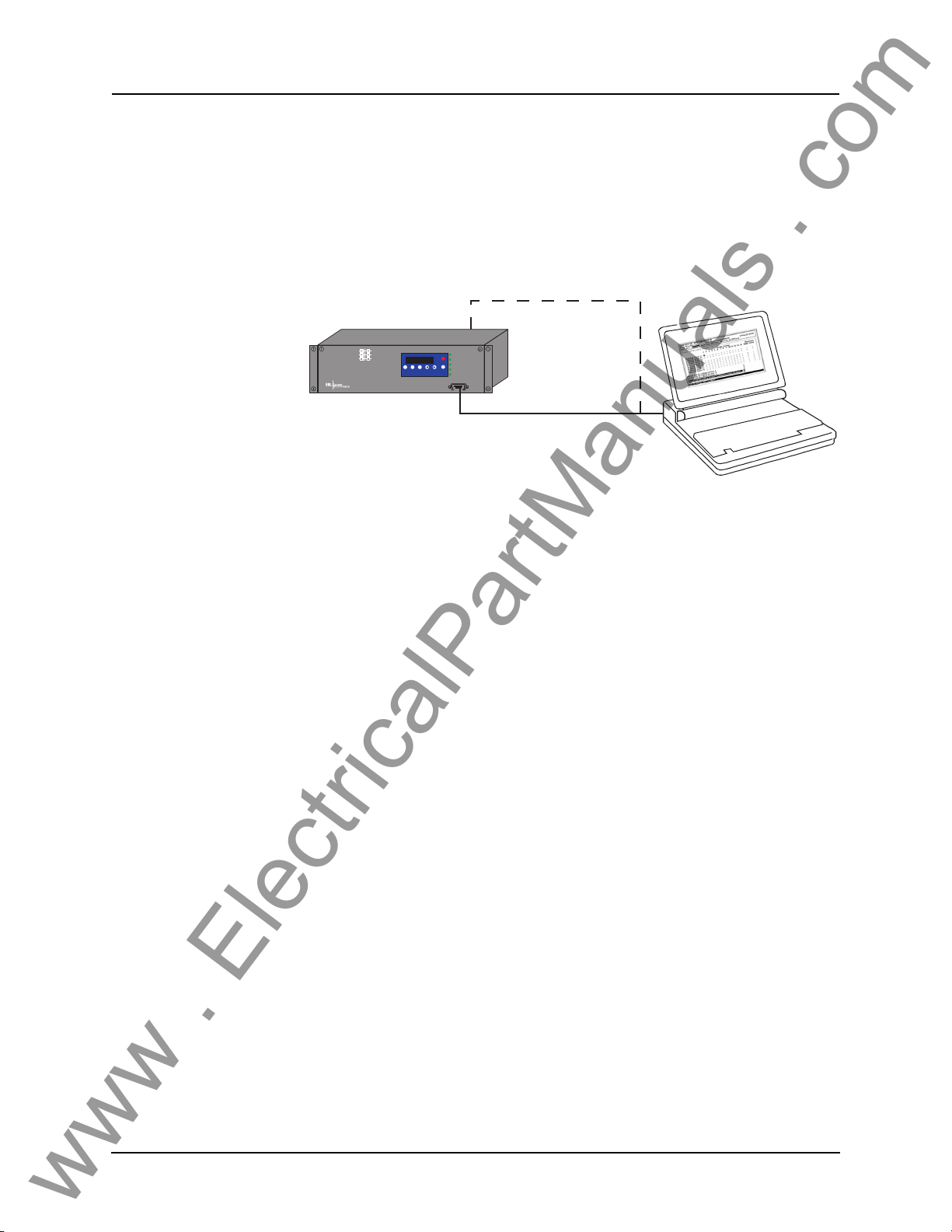
Figure 2.1: Direct Serial Link
The relay has three serial ports that provide direct access to its user interface
and SCADA services.
All of the relay’s serial ports (Ports 1, 2 and 3) are configured as EIA
RS-232
Data Communications Equipment (DCE) devices with female DB9 connectors. This allows them
dard straight-through male-to-female serial cable, for pin-out,
to be connected directly to a PC serial port with a stan-
for details see
“Communication Port Details” on page 2-8.
The relay’s user interface is accessed through a
ulation program running on a PC. To create a direc
lay and your computer, connect the seri
al cable (provided) between your
standard VT-100 terminal em-
t serial link between the re-
computer's serial port and Port 1 on the relay’s front panel. Port 2 on the relay’s
back panel can also be used for direct serial access, provided the port is not
configured for modem use. When connected, run the terminal emulation software on your computer to establish the communication link, for details see
“Using HyperTerminal to Access the Relay’s User Interface” on page 2-5.
The relay’s Modbus and DNP3 SCADA services can be accessed via a direct
serial
link to Port 3 on the relay’s back panel, for details see “Accessing the
SCADA Services” on page 2-7.
2-2 B-PRO User Manual 8700 D01908R02.12
Page 21
Modem Link -
www . ElectricalPartManuals . com
External
2 Setup and Communications
Port 5 - RJ-11 modem
B-PRO
BUS PROTECTION RELAY
MODEL 8700/BUS
2000 JAN 07
View
View
Date &
Readings
Logs
Time
Analog
Telephone
Line
RELAY FUNCTIONAL
IRIG-B FUNCTIONAL
Target
SERVICE REQUIRED
TEST MODE
Next
Prev
Clear
Target
ALARM
PORT 1
Telephone
System
Analog
Telephone
Line
Desktop Computer
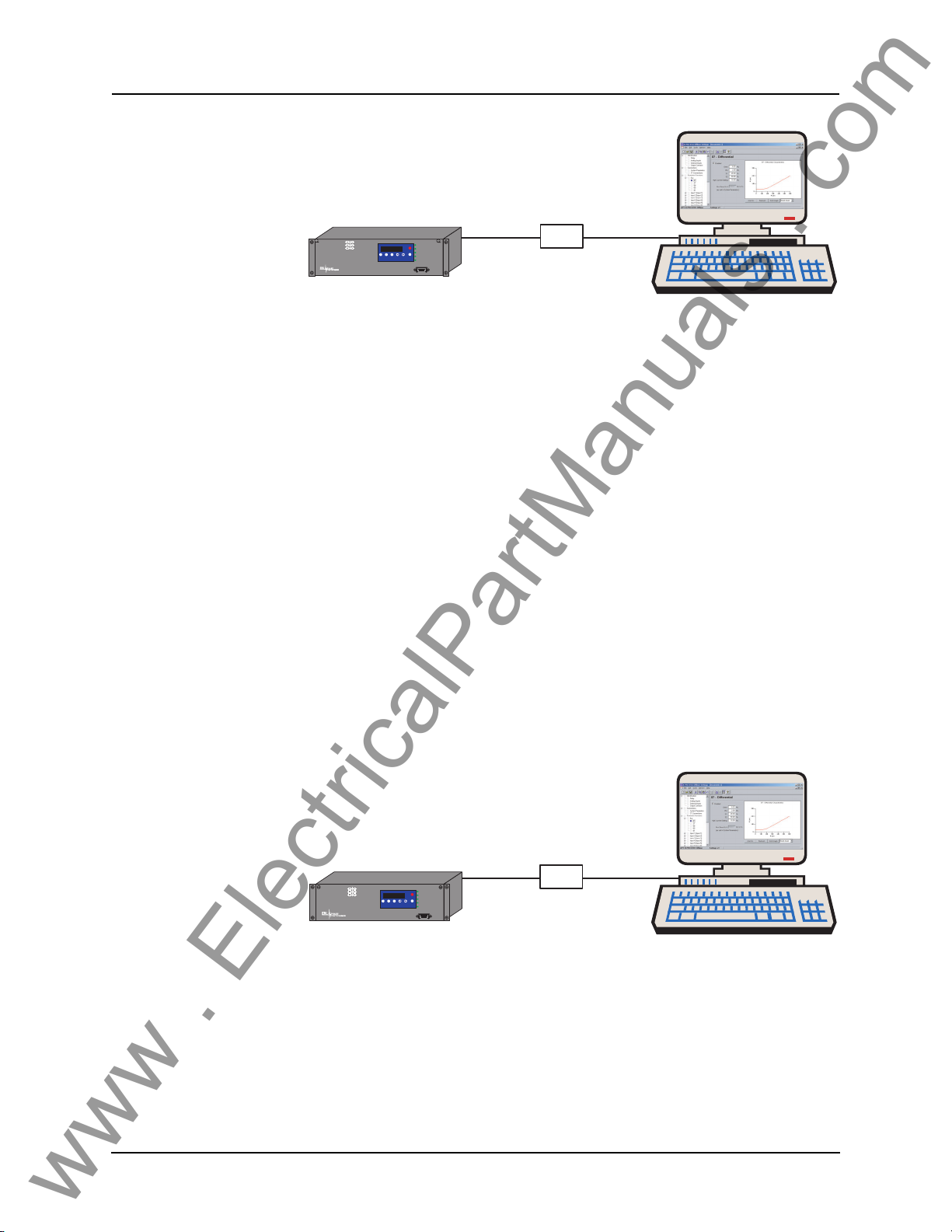
Figure 2.2: External Modem Link
Using an external modem, you can also access the relay’s user interface
through a telephone link between the relay and your computer.
Connect the serial port on the external mode
m to Port 2 on the relay’s back
panel. Both devices are configured as RS-232 DCE devices with female connectors, so the cable between the relay a
nd the modem requires a crossover and
a gender change. Alternatively, you can use the ERLPhase modem port adapter
provided with the relay to make Port 2 appear the same as a PC’s serial port. A
standard modem-to-PC serial cable can then be used to connect the modem and
the relay. For pin-out details see “Communication Port Details” on page 2-8.
Connect the modem to an analog telephone line or switc
h using a standard RJ-
11 connector.
You must appropriately configure the relay’s Port 2
to work with a modem.
Log into the relay through a direct serial link, go to the Utilities>Setup>Ports
screen, and set Port 2 Modem option to Yes. Set the Baud Rate as high as possible — most modems handle 57,600 bps. The Init
ialize setting allows you to
set the control codes sent to the modem at the start of each connection session.
The factory defaults are: “M0S0=0&B1” for an external modem and
“M0S0=0” for an internal modem.
Modem Link -
rnal
Inte
Port 5 - RJ-11 modem
B-PRO
BUS PROTECTION RELAY
MODEL 8700/BUS
2000 JAN 07
View
View
Prev
Date &
Readings
Logs
Time
Analog
Telephone
Line
Telephone
RELAY FUNCTIONAL
IRIG-B FUNCTIONAL
Target
SERVICE REQUIRED
TEST MODE
Next
Clear
Target
ALARM
PORT 1
System
Analog
Telephone
Line
Desktop Computer
Figure 2.3: Internal Modem Link
You can access the relay’s user interface through a telephone link between the
relay and your computer using an optional internal modem. If the modem has
been installed, Port 5 on the rear panel is labelled “INTERNAL MODEM.”
Connect the relay’s Port 5 to an analog telephone
line or switch using a stan-
dard RJ-11 connector.
D01908R02.12 B-PRO User Manual 8700 2-3
Page 22
2 Setup and Communications
www . ElectricalPartManuals . com
Network Link
When an internal modem is installed, the relay’s Port 2 is used to interface to
the modem internally. Appropriate Port 2 settings are configured at the factory
when the internal modem is installed. The factory defaults are: “M0S0=0&B1”
for an external modem and “M0S0=0” for an internal modem.
PC with TCP/IP
B-PRO
BUS PROTECTION RELAY
MODEL 8700/BUS
10BaseT
Port 5 - RJ-45
2000 JAN 07
View
Date &
Readings
Time
Network
Target
Next
View
Prev
Clear
Logs
Target
RELAY FUNCTIONAL
IRIG-B FUNCTIONAL
SERVICE REQUIRED
TEST MODE
ALARM
PORT 1
TCP/IP
Network
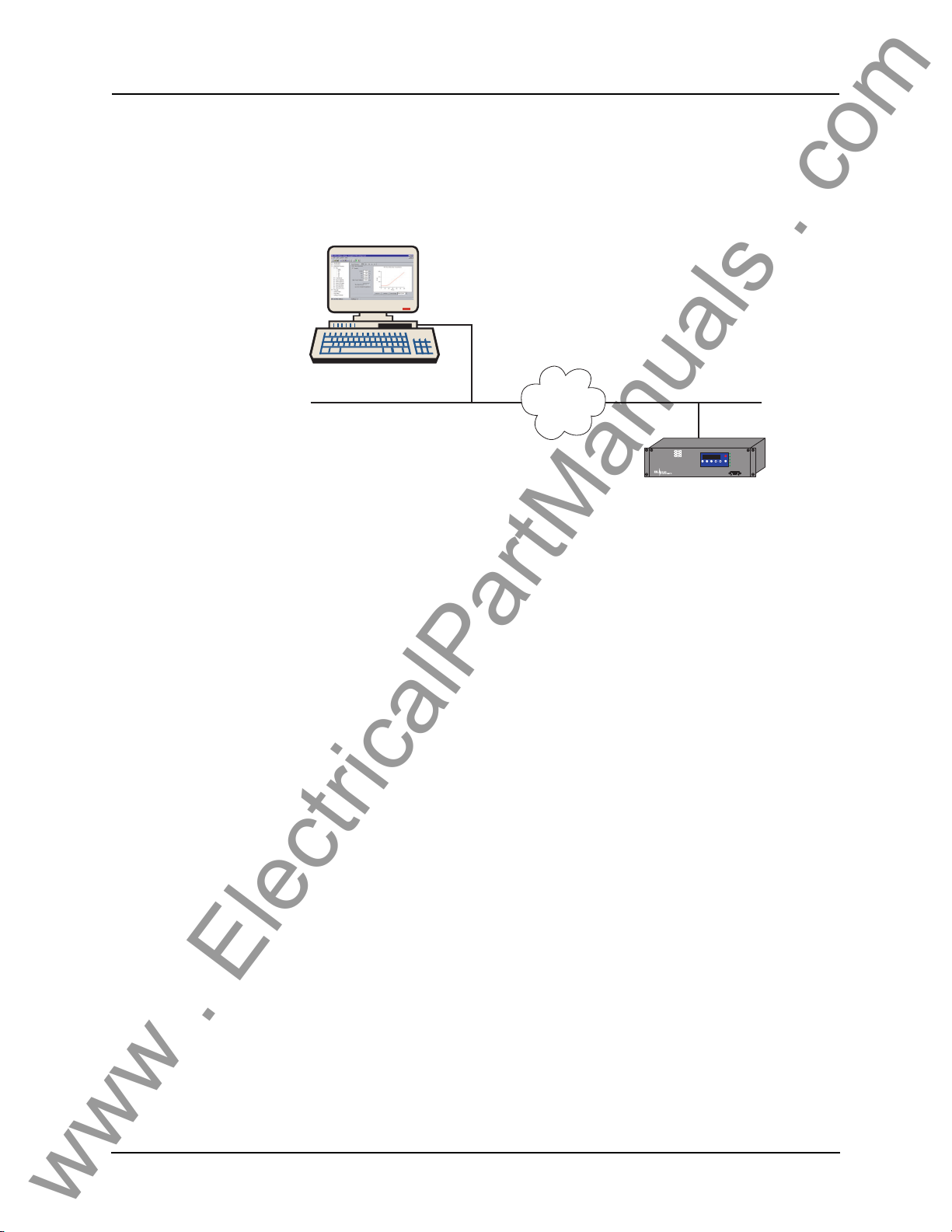
Figure 2.4: Network Link
You can access both the relay’s user interface and DNP3 SCADA services simultaneously through the same network port with an
optional Ethernet TCP/IP
LAN link. If the Ethernet option has been installed, Port 5 on the rear panel will
be labelled “NETWORK.”
The user interface accessed through the LAN is the same as that available
through
a direct serial connection or a modem link, but requires the use of a
Telnet client on your PC. The HyperTerminal program included with Microsoft Windows provides Telnet services. To
select Telnet, go to HyperTerminal’s Properties dialog box and set the Connect Using field to TCP/IP
(Winsock). If t
his option is not available in the pick list, you require a newer
version of HyperTerminal (v1.2 or greater). Alternatively, you can use any
Telnet program that fully supports VT-100 terminal emulation and z-modem
file transfer.
DNP3 SCADA services can also be accessed over the LAN, for details see
“Accessing the SCADA Services” on page 2-7.
Connect Port 5 to the Ethernet LAN using
an appropriate 10BaseT cable with
an RJ-45 connector. The relay supports 10 Mbit Ethernet, although a dual
speed 10/100 Ethernet hub or switch can be used.
By default, the relay is assigned an IP address of 192.168.1.100. If this address
is not suitable, it
may be modified using the relay’s Maintenance Menu. For
details see “Using HyperTerminal to Access the Relay’s User Interface” on
page 2-5.
2-4 B-PRO User Manual 8700 D01908R02.12
Page 23
2 Setup and Communications
www . ElectricalPartManuals . com
Using HyperTerminal to Access the Relay’s User Interface
Change settings, view measured values and retrieve data from the relay using
its user interface. This section describes how to configure a standard Windows
VT-100 terminal program on your PC for use with the relay.
The computer must be connected to the relay by one of its serial, modem or
rnet communication ports, for details see “Communicating with the Relay
Ethe
(IED)” on page 2-2.
The relay user interface is accessed using a sta
program on your computer eliminating the need for specialized user interface
software. Any terminal program that fully supports VT-100 emulation and provides z-modem file transfer services can be used. The
included with Microsoft Windows is used here as an example.
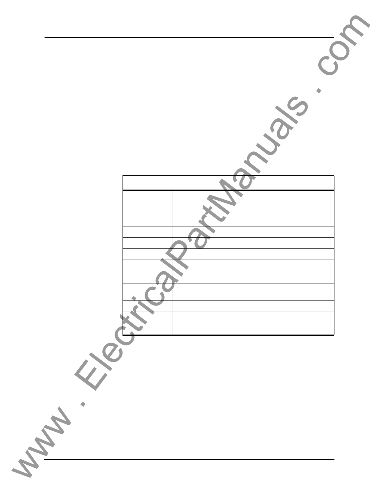
Configure your terminal program as described in
the appropriate serial port, modem or TCP/IP socket on your computer.
Terminal Program Setup
Baud rate For a direct serial link the baud rate must match that of the relay serial
port.
For a modem link the baud rate refers only to the link between your
computer a
Refer to “Setting the Baud Rate” on page 2-6 for further information.
nd its own modem.
ndard VT-100 terminal style
HyperTerminal program
the table below and link it to
Data bits 8
Parity None
Stop bits 1
Flow control Hardware or Software.
Hardware flow control is recommended. The relay automatically supports both on all its serial ports.
Function, arrow
and contro
Emulation VT100
Font Use a font that supports line drawing (e.g. Terminal or MS Line Draw).
l keys
To initiate a connection with the relay use HyperTerminal’s Ca
Terminal keys
If the menu appears outlined in odd characters, the font you have
selected is
not supporting line drawing characters.
ll>Connect
function.
When the connection is established, press Enter in the
terminal window to
bring up the following login prompt.
D01908R02.12 B-PRO User Manual 8700 2-5
Page 24
2 Setup and Communications
www . ElectricalPartManuals . com
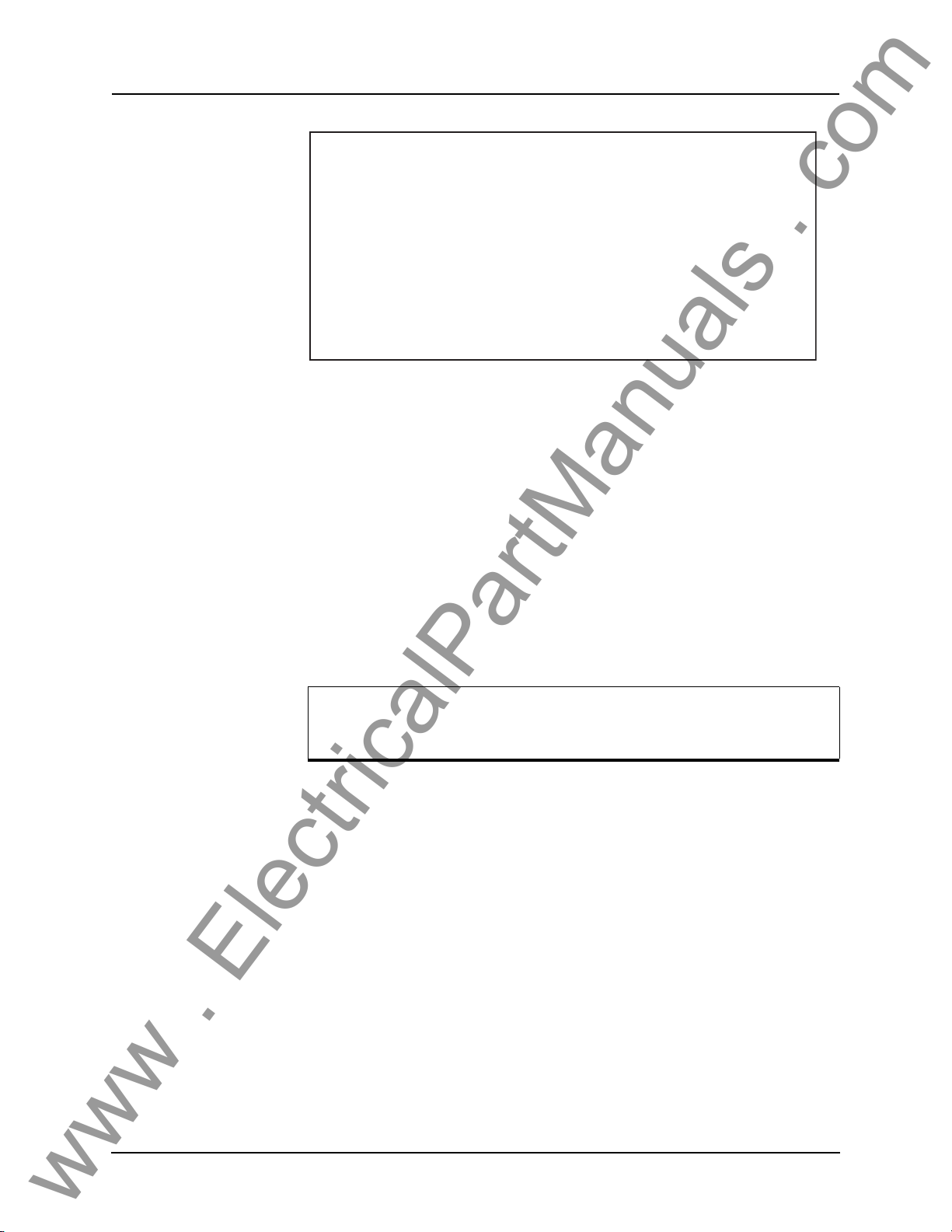
------- NxtPhase B-PRO 8700 Terminal User Interface login -------
Log in using one of the following usernames:
'view' - read-only access to settings and readings
'change' - read/write access to settings and readings
'service' - full access to all functions (Port 1 access only)
'maintenance' - access to the maintenance menu
'update' - to load a firmware update
Notes:
- Serial and modem connections have a 60 minute inactivity timeout
- Usernames and passwords are case sensitive
login:
Instructions for logging in and running the user interface are given in “Terminal Mode” on page 3-4.
If you see incorrect characters on a direct
is a mismatch between the relay’s baud rate and that of the PC.
serial connection, it may mean there
Ending a User
Inte
rface Session
Use the Quit function in the relay’s user menu to end a session. This closes the
interface and requires the next user to login to the relay.
The relay automatically ends a session when it detec
direct serial cable or a modem hang-up. For other types of connections (e.g. serial switches or Ethernet) use the Quit function to ensure the interface is closed
and login
protection is activated.
ts the disconnecting of a
Setting the Baud Rate
The baud rate of the relay’s serial ports can be shown on the relay’s
front panel display. From the main Date & Time display, press the
Next button.
Direct Serial Link For a direct serial connection both the relay and your computer must be set to
the same baud rate.
To change the baud rate of a relay serial port:
1 Access the relay’s user interface through any of the available ports.
2 Login to the user interface and go to the Utiliti
details see “Terminal Mode” on page 3-4.
3 Select the desired baud rate for the appropriate port by toggling through the
options using
The message “New communications settings loaded” will appear.
The new baud rate will be used on that
the Space or Enter keys. Save the new setting with the F2 key.
port the next time you login to it.
es>Setup>Ports menu, for
To change the baud rate on your computer’s serial port:
1 From HyperTerminal bring up the Properties dialog box, press the Config-
utton and set the baud rate field to the desired value.
ure b
2 Save the changes.
2-6 B-PRO User Manual 8700 D01908R02.12
Page 25

2 Setup and Communications
www . ElectricalPartManuals . com
Modem Link Unlike a direct serial link, the baud rates for a modem link do not have to be
the same on your computer and on the relay. The modems automatically negotiate an optimal baud rate for their communication.
The baud rate set on the relay only affe
nicates with the modem. Similarly, the
fects the rate at which your computer communicates with its modem. Details
on how to se
ternal” on page 2-3, except that you modify the Port 2
and the properties of the modem in HyperTerminal.
t these respective baud rates are described in “Modem Link - Ex-
cts the rate at which the relay commu-
baud rate set in HyperTerminal only af-
baud rate on the relay
Accessing the SCADA Services
The relay supports DNP3 (Level 2) and Modbus SCADA protocols as a standard feature on all relays. DNP3 is available through a
Ethernet LAN on top of either TCP or UDP protocols. The Modbus implementation supports both RTU (binary) or A
direct serial link.
The relay’s Port 3 is dedicated for use with
Port 3 uses standard RS-232 signalling. An external RS-232<->RS-485 converter can also be used to connect to an RS-485 network.
For details on connecting to serial Port 3 see “Communicating with the Relay
(IED)” on page 2-2 and “Communication Port Details” on page 2-8.
The DNP3 protocol can also be run across the optional Ethernet LAN. Both
DNP over
the Ethernet LAN see “Network Link” on page 2-4.
Complete details on the Modb
“Modbus RTU Communication Protocol” in Appendix E and “DNP3 Communication Protocol” in Appendix F.
TCP and DNP over UDP are supported, for details on connecting to
us and DNP3 protocol services can be found in
SCII modes and is available through a
Modbus or DNP3 serial protocols.
direct serial link or the
Protocol Selection To select the desired SCADA protocol, login
access the Utilities>Setup>SCADA menu. Select the protocol and set the corresponding parameters.
The DNP3 LAN/WAN - TCP and UDP options are only available if the
unit has an o
Ensure the Master IP Address is different from the relay’s IP Address.
Communication Parameters
Diagnostics Protocol monitor utilities are available
D01908R02.12 B-PRO User Manual 8700 2-7
Port 3’s communication paramete
menu in relay’s user interface. Both the baud rate and the parity bit can be configured. The number of data bits and stop bits are
the selected SCADA protocol. Modbus ASCII uses 7 data bits. Modbus RTU
and DNP Serial use 8 data bits. All protocols use 1 stop bit except in the case
where either Modbus protocol is used with no parity; this uses 2 stop bits, as
defined in the Modbus standard.
nication difficulties such as incompatible
ptional Ethernet LAN port installed.
rs are set using the Utilities>Setup>Ports
to assist in resolving SCADA commu-
to the relay’s user interface and
determined automatically by
baud rate or addressing. The utilities
Page 26
2 Setup and Communications
www . ElectricalPartManuals . com
can be accessed through the Maintenance user interface, for details see “Maintenance Menu” on page 2-11.
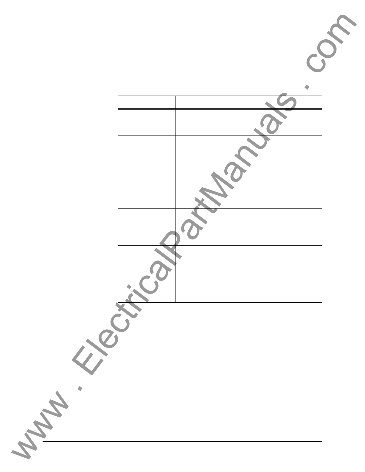
Communication Port Details
Port Location Function
1 Front Panel RS-232 Data Communication Equipment (DCE) female DB9.
2 Rear Panel RS-232 DCE female DB9.
Used for user interface access thro
Default Setting: 38,400 baud, 8 data bits, no parity, 1 stop bit.
Used for:
• User interface access thr
• User interface access through an external modem. The optional
ERLPhase Mode
nal Equipment (DTE) to simplify co
modem.
Default Setting: 9,600 baud, 8 data bits, no parity, 1 stop bit.
Port 2 is disabled if the relay is equipped with an internal modem
see Port 5).
(
m Adapter converts this port to a Data Termi-
ugh a direct serial connection.
ough a direct serial connection.
nnection to an external
3 Rear Panel RS-232 DCE female DB9.
Used for SCADA communication.
Default Setting: 9,600 baud, 8 data bits, no parity, 1 stop bit.
4 Rear Panel Not used
5 Rear Panel RJ-11/RJ-45 receptacle.
When equipped with optional internal modem:
• Used for user interface access through modem.
When equipped with optional internal Ethernet card:
• User interface access.
• DNP SCADA access.
Default Ethernet IP address: 192.168.1.100.
2-8 B-PRO User Manual 8700 D01908R02.12
Page 27
2 Setup and Communications
www . ElectricalPartManuals . com
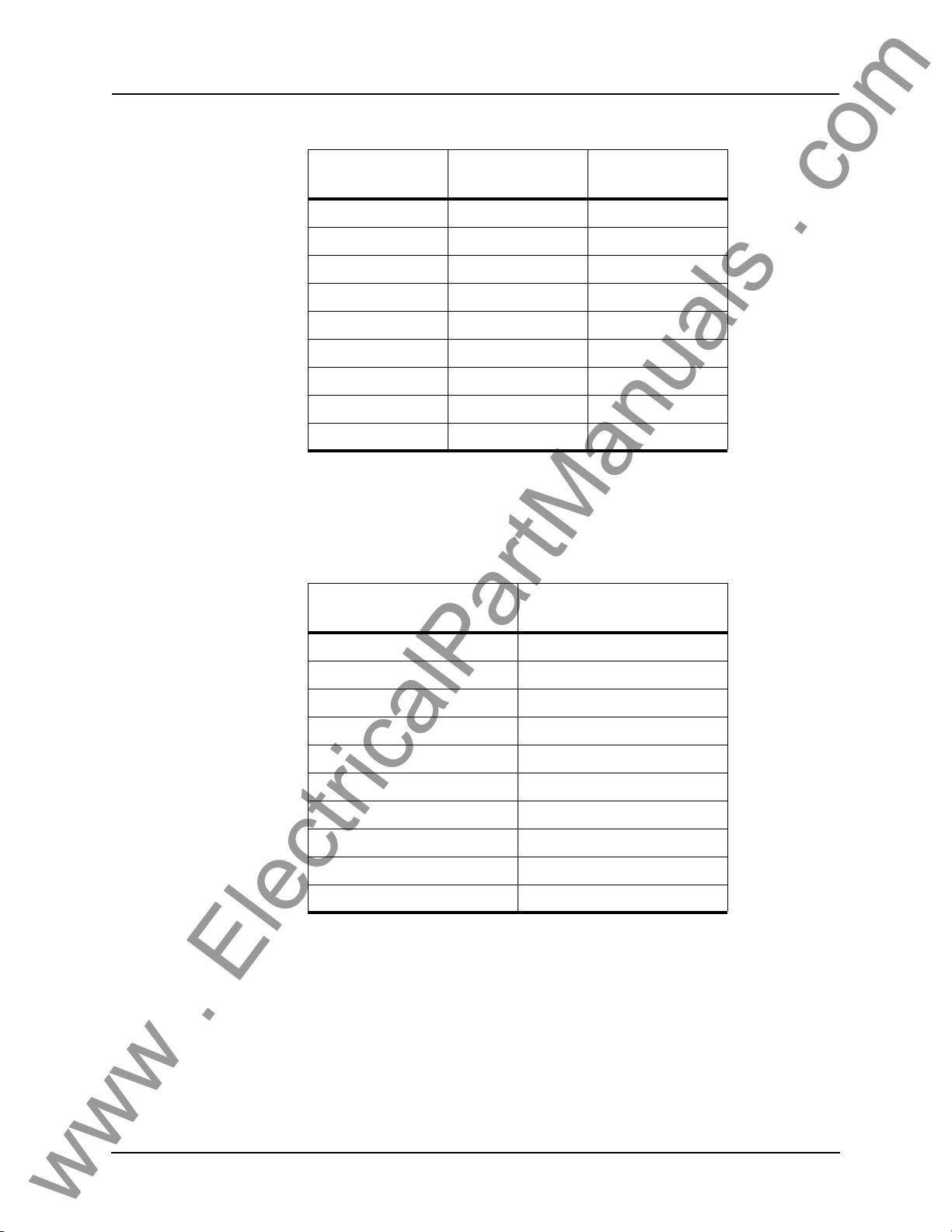
Signal Name
DCD ← 1
RxD ← 2
TxD → 3
DTR → 4
Common 5
DSR ← 6
RTS → 7
CTS ← 8
No connection 9
Direction
PC<-> Relay
Pin # on the Relay
Port
Notes:
• Relay is DCE, PC is DTE
• Pins 1 and 6 are tied together internal to the relay
Male DB-9 Cable End for Relay
Port
Female DB-9 Cable End for
Com
puter Port
Pin # on Cable Pin # on Cable
1 1
2 2
3 3
4 4
5 5
6 6
7 7
8 8
9 9
D01908R02.12 B-PRO User Manual 8700 2-9
Page 28
2 Setup and Communications
www . ElectricalPartManuals . com
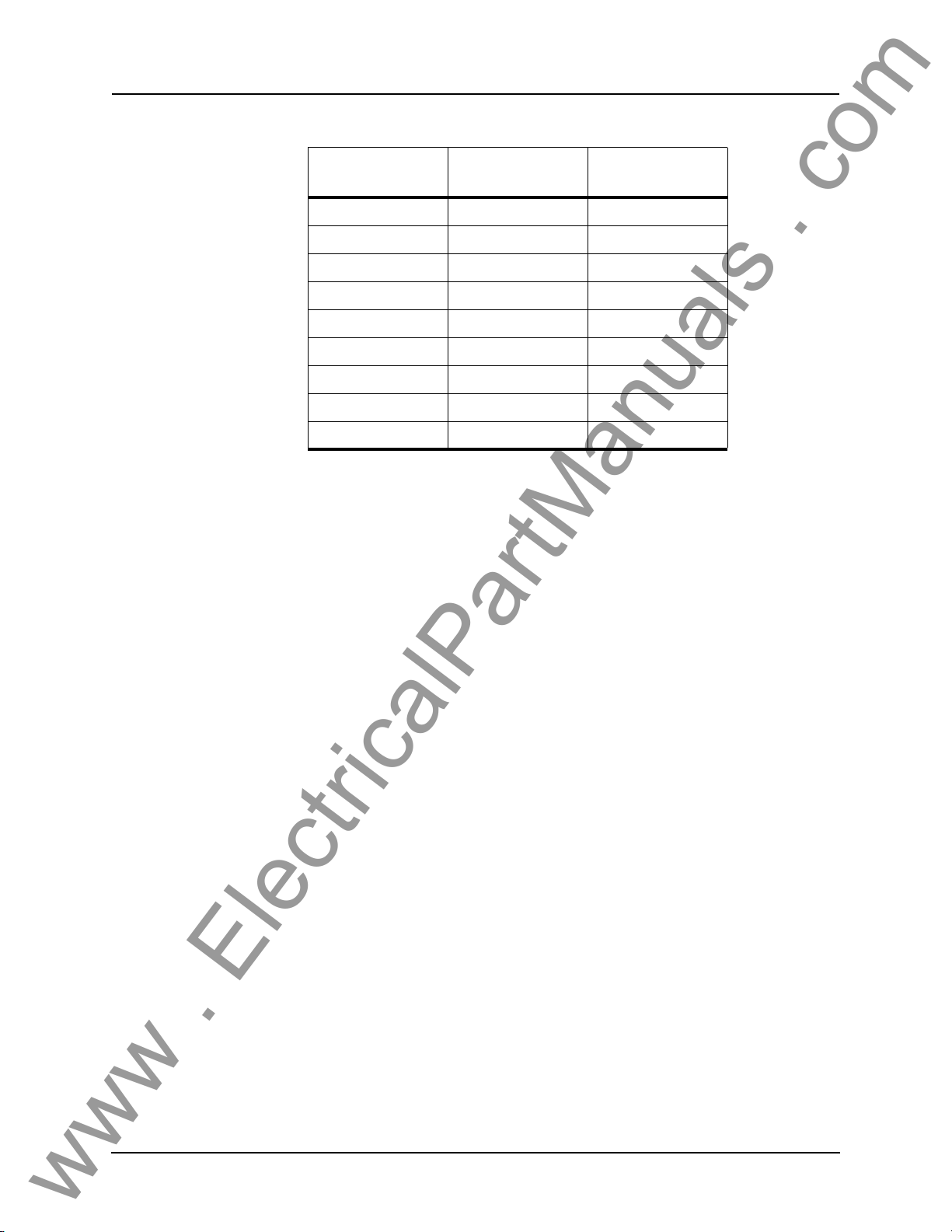
Signal Name
DCD → 1
RxD → 2
TxD ← 3
DTR ← 4
Common 5
DSR → 6
RTS ← 7
CTS → 8
No connection 9
Direction
Modem <-> Relay
Pin # on the Modem
Ad
apter
Notes:
• Relay (with modem adapter) is DTE,
modem is DCE
• Pins 1 and 6 are tied together internal to the relay
2-10 B-PRO User Manual 8700 D01908R02.12
Page 29
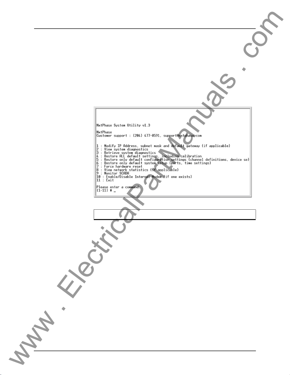
Maintenance Menu
www . ElectricalPartManuals . com
The relay has a Maintenance Menu that can be accessed by connection through
a VT-100 terminal emulator (such as the HyperTerminal program that comes
with MS Windows). Using either direct serial or modem connection:
1 Use the terminal program to connect to
2 Select Ent
3 Login as “maintenance” in lower case.
A menu appears as below.
2 Setup and Communications
the serial port, either through direct
serial link or modem.
er, the relay responds with a login prompt.
Commands 1, 4, 5, 6, 7 and 10 are Port 1 access only.
D01908R02.12 B-PRO User Manual 8700 2-11
Page 30
2 Setup and Communications
www . ElectricalPartManuals . com
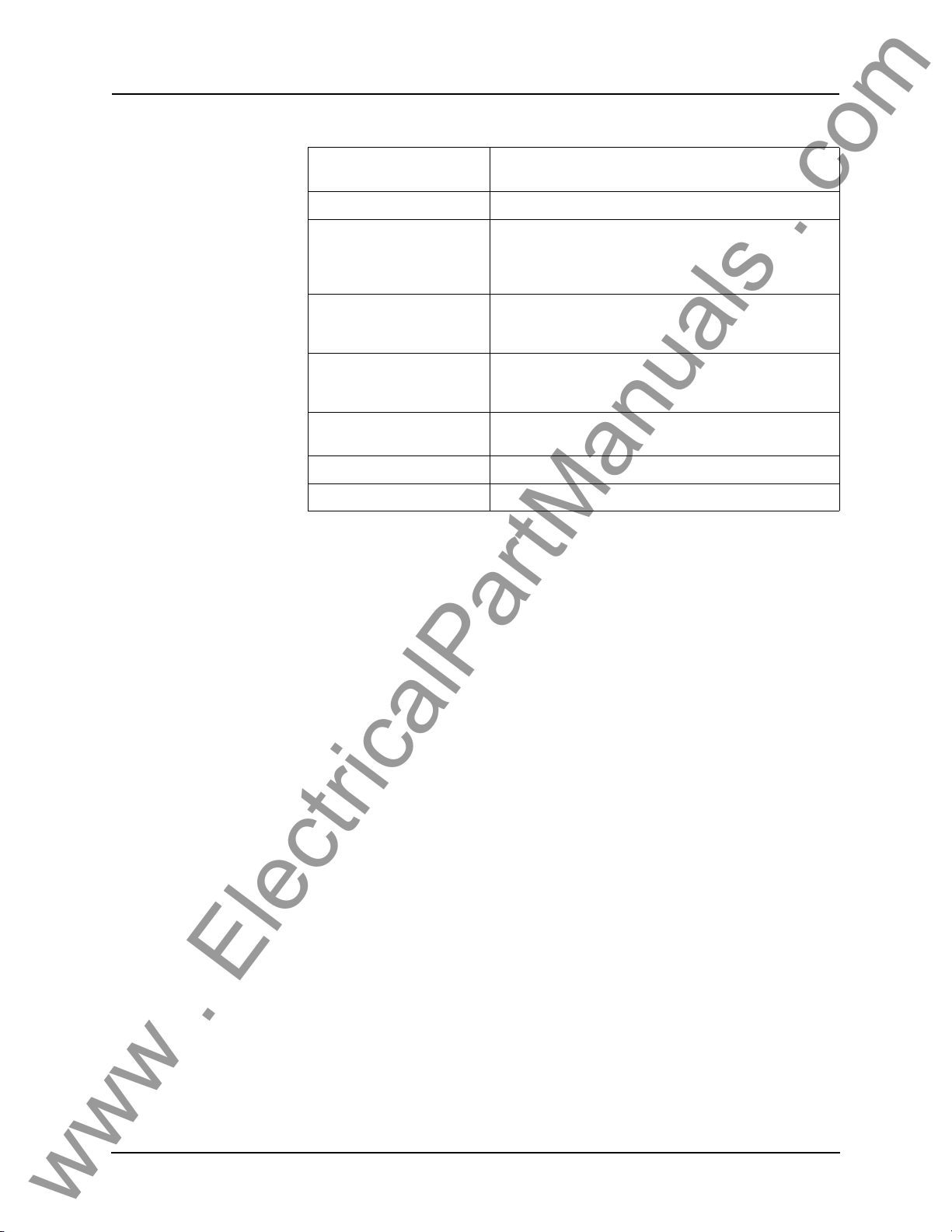
Modify IP address Modifies the LAN IP address when equipped with an
optional internal 10BaseT Ethernet card.
View system diagnostic Displays the internal status log.
Firmware Update
Retrieve system diagnostics Automatically packages up the inter
Restore settings Use this menu to force the system back to default values, if
Force hardware reset Manually initiates a hardware reset. Note that the communi-
View network statistics View IP, TCP and UDP statistics when equipped with inter-
Monitor SCADA Shows real time display of SCADA data.
Enable/disable Modem Enables or disables the internal modem.
ting and setup information and downloads it in compressed
form
to your computer. This file can then be sent to our cus-
tomer support to help diagnose a problem.
spect a problem due to the unit’s settings, calibration
you su
and/or setup parameters.
cation link is immediately lost and cannot be re-established
e unit completes its start-up.
until th
nal 10BaseT Ethernet card.
nal status log plus set-
The relay has an update login that can be accessed by a connection through a
VT100 terminal emulator (such as HyperTerminal). This login is available
only from Port 1.
1 Use the terminal program to connect to Port 1.
2 Select Ent
3 Login as update in
The firmware update is used to update
er, the terminal responds with a login prompt.
lower case.
the relay’s software with maintenance
or enhancement releases. Please see the B-PRO Firmware Update Procedure
documentation that comes with the firmware update for instructions on how to
update the firmware on the relay.
2-12 B-PRO User Manual 8700 D01908R02.12
Page 31
3 Using the IED (Getting Started)
www . ElectricalPartManuals . com
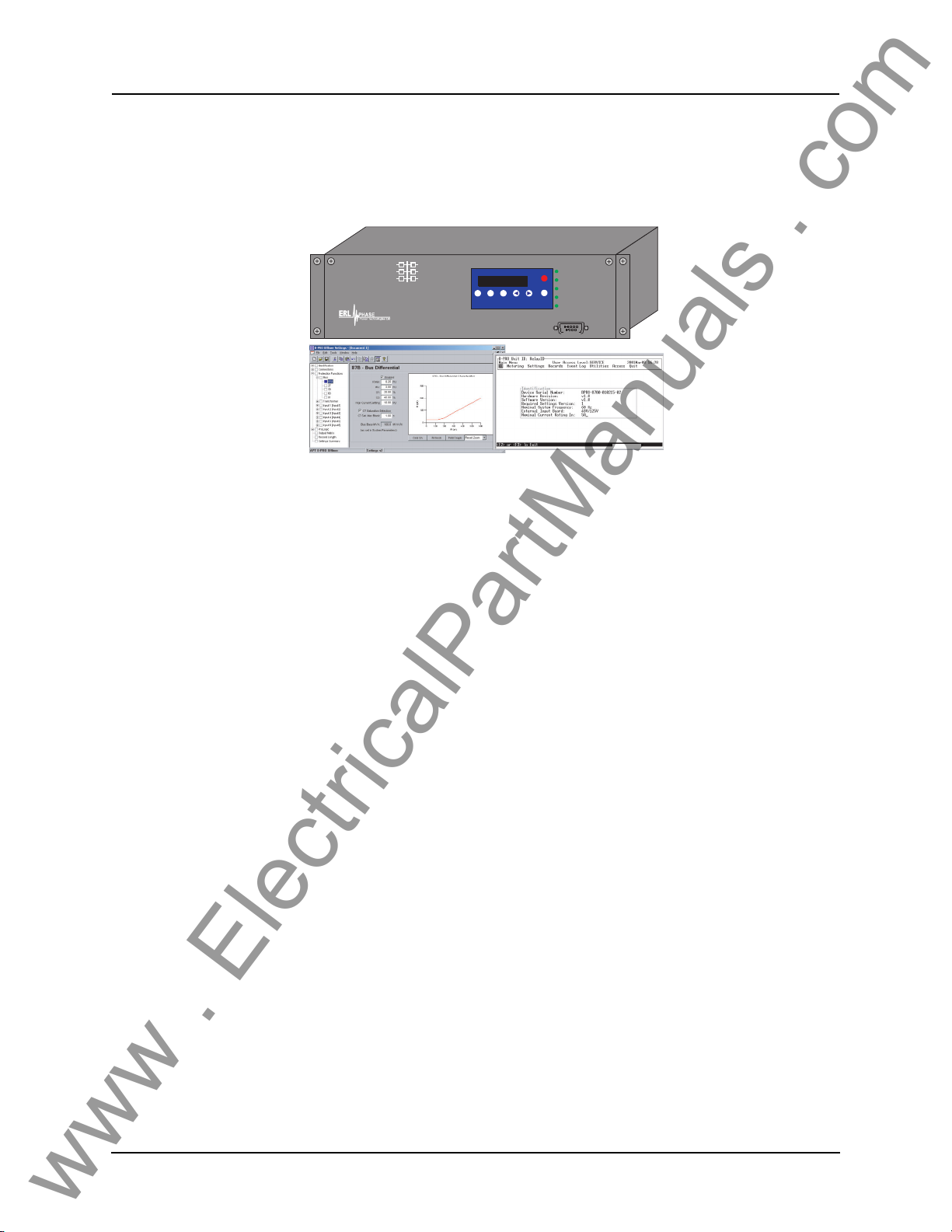
B-PRO Bus Protection Relay
Offline Mode - Settings Software
Start-up Sequence
The following initialization sequence takes place:
Test Mode—red LED on 2 seconds after power applied
Relay Functional—green LED on 5 seconds after power applied
Front Display—on 30 seconds after power applied
Test Mode—red LED off 40 seconds after power applied
B-PRO
BUS PROTECTION RELAY
MODEL 8700/BUS
2000 JAN 07
Next
View
View
Prev
Date &
Readings
Logs
Time
B
Online Mode -Terminal Mode
Target
Clear
Target
RELAY FUNCTIONAL
IRIG-B FUNCTIONAL
SERVICE REQUIRED
TEST MODE
ALARM
PORT 1
2000Dec14
When the relay is powered up, the normal sequenc
e of LED operation is Test
Mode followed by Relay Functional and IRIG-B Functional (if available), display on, then Test Mode off. The
entire sequence takes about 40 seconds.
Ways to interface with B-PRO:
• Front panel display
• Terminal Mode
• Offliner S
D01908R02.12 B-PRO User Manual 8700 3-1
ettings software (Details in Chapter 5-1)
Page 32
3 Using the IED (Getting Started)
www . ElectricalPartManuals . com
Front Panel Display
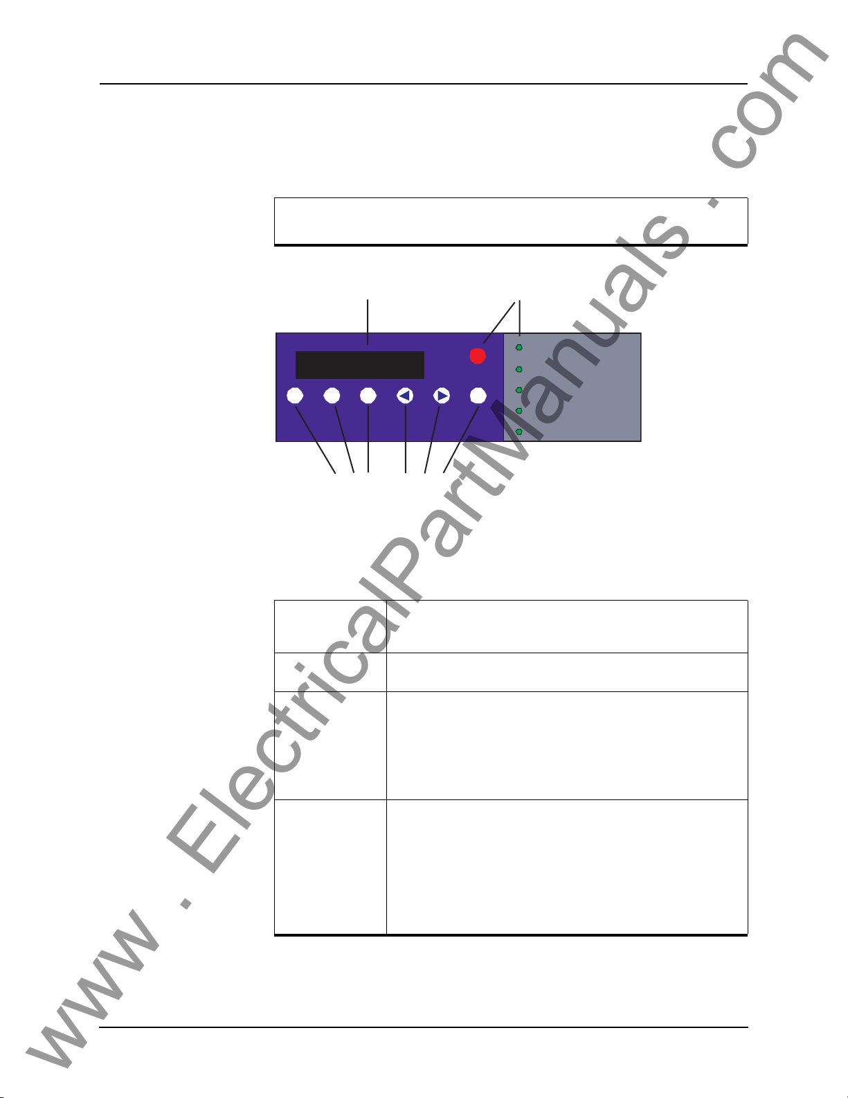
The front panel display is the fastest and easiest way of getting information from the relay.
View or change settings using Terminal Mode or loading a setting file
from Offlin
Date &
Time
er Settings.
Display LED Lights
2000 JUL 07 13:22:07
VIiew
View
Readings
Logs
Previous Next
Target
Clear
Target
Relay Functional
IRIG-B Functional
Service Required
Test Mode
Alarm
LED Lights
Push Buttons
Figure 3.1: Front Panel Display
The front panel consists of a display, six LED lights and six push buttons.
Relay
Functional
IRIG-B
Functional
Service Required Indicates the relay needs service. This LED can be the same state as
Test M o d e Occurs when the relay output contact
Indicates when the relay is functional. When the Relay Functional
green LED goes on, the rear Relay Inoperative contact changes to an
open and the protective functions become functional.
Indicates the presence of a valid IRIGon.
Relay Functional LED or can be of the opposite state depending on
the
the nature of the problem.
The following items bring up this LED:
• DSP failure - protection difficulties within
• Communication failure within the relay.
• Internal relay problems.
Possible reasons are:
• Relay initialization on startup
• User interface processor has reset and is being tested.
You cannot communicate with the relay through the ports until the front
display becomes
the red Target LED remains off after this start-up unless the relay had
unviewed target messages.
active and the TEST MODE LED goes out. Normally,
B time signal where the LED is
the relay.
s are intentionally blocked.
3-2 B-PRO User Manual 8700 D01908R02.12
Page 33
Push Buttons
www . ElectricalPartManuals . com
3 Using the IED (Getting Started)
Alarm Occurs when an enabled relay function picks up.
The red Alarm LED should be off if there are no inputs to the relay. If
the Alarm LED is on, check the e
play by pressing the V
Target Indicates that a fault has taken place. In the output matrix select which
output cont
Date &Time Pressing the Date &Time button displays the date and time stored on
the relay. If the time is incorrect, connect to a PC in Terminal Mode and
go to Utilities>Setup>Time to make the change or connect to the IRIGB plug at the back of the relay. The front display time and date is automatically updated.
The green IRIG-B Functional LED comes on. The relay accepts either
modulated o
IRIG-B such as time skew for different time zones are available when
you establish communication with the PC.
acts you want to activate when an alarm occurs.
r unmodulated IRIG-B signals automatically. Options using
iew Logs button.
vent log messages on the front dis-
View Readings Pressing the View Readings button obtains metering information about
View Logs Pressing the View Logs button displays the target information, if a relay
Previous/Next Scroll through the menu by pressing Previous and Next. When the
Clear Target Use the Clear Target button to view all
s, for details see “Metering Data” on page 3-14.
the line
oper
ation has occurred.
Date & T
display the Port 1 and Port 2 baud rates.
takes place, the red target light appears. If many faults have been
stored, you may need to push this button several times. Clearing the
target light does not clear the target information from the relay log.
The relay holds all target messages during a pow
and restart. Pressing the Clear Target push button displays any targets
not previously viewed on the front display and clears the Target LED
after the last target has been viewed.
ime is being displayed, pressing either of these buttons will
target information. When a fault
er supply shutdown
D01908R02.12 B-PRO User Manual 8700 3-3
Page 34
3 Using the IED (Getting Started)
www . ElectricalPartManuals . com
Display
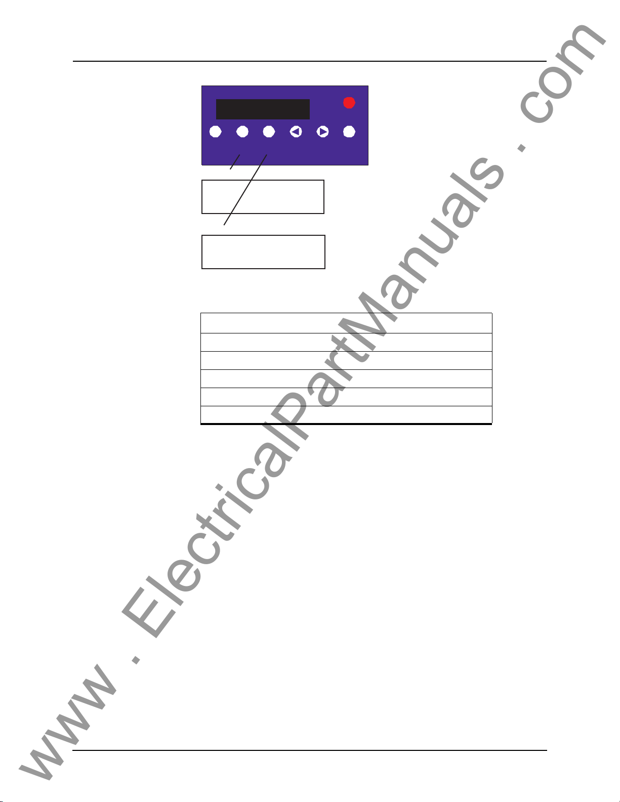
2000 JUL 07 13:22:07
View
View
Date &
Readings
Time
V
iew
R
ea
ding
Pri V 0.0 KV ph–ph
Freq. 60, 0 Hz
V
iew Log
2000Jun28 19:34:31.823
Line 5 Device 51 Trip
Figure 3.2: Display Examples
s
Logs
s
Previous Next
Target
Clear
Target
Front Panel Display Messages
PRI V, Frequency
Va, Vb, Vc magnitude and angle of bus PT
Ia, Ib, Ic magnitude and angle of each CT input
P and Q of each line
Tripping device targets, times and dates
For a detailed description of the metering data provided by the relay, see "Metering Data" on Page 3-14
Terminal Mode
The Terminal User Interface (TUI) is the main method of interaction between
the relay and the user. From here the user can set the relay, load a setting file,
view metering information, create and retrieve recordings, view logs, set-up
system parameters and review system information. The following steps describe how to access the TUI.
Accessing TUI 1 Establish terminal mode connection, for details see “Using HyperTerminal
to Access the Relay’s User Interface” on page 2-5.
3-4 B-PRO User Manual 8700 D01908R02.12
Page 35
3 Using the IED (Getting Started)
www . ElectricalPartManuals . com
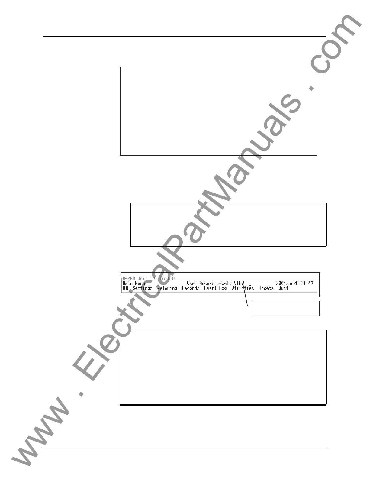
2 When the connection is established and the terminal mode program appears
on your screen, the following prompt should appear. If it doesn’t appear,
press ENTER.
------- NxtPhase B-PRO 8700 Terminal User Interface login -------
Log in using one of the following usernames:
'view' - read-only access to settings and readings
'change' - read/write access to settings and readings
'service' - full access to all functions (Port 1 access only)
'maintenance' - access to the maintenance menu
'update' - to load a firmware update
Notes:
- Serial and modem connections have a 60 minute inactivity timeout
- Usernames and passwords are case sensitive
login:
3 Login as one of vie
names provide differing levels of permission, for details see “Access Levels” on page 3-5. Maintenance and Update are explained in “Maintenance
Menu” on page 2-11 and “Firmware Update” on page 2-12.
The relay supports the optional use of passwords. A pop-up dialogue box appears after login has taken place.
If you have forgotten the password, go to Ac
Terminal Mode, for details see “Passwords” on page 3-6.
4 If login is successful, the Main Menu appears:
If the box around the menu does not appear as above, change the
t in your terminal program to one that supports line draw charac-
fon
ters, e.g. terminal fonts. Also ensure tha
(not VT100J).
w, change or service (lower case). These three login
cess>Passwords in
view, change or service
(depends on how you log in)
t emulation is set to VT100
If there are incorrect characters in the display, improper line feeds or
une
rased portions, the baud rate is too high for the quality of the communication link. Use the Util
lay’s baud rate. The new rate is in effect at the next connection.
Access Levels The relay supports three user access levels that cont
available to you. The current access level is always shown in the centre of the
Main Menu heading.
D01908R02.12 B-PRO User Manual 8700 3-5
ities>Setup>Ports menu to reduce the re-
rol what relay functions are
Page 36
3 Using the IED (Getting Started)
www . ElectricalPartManuals . com
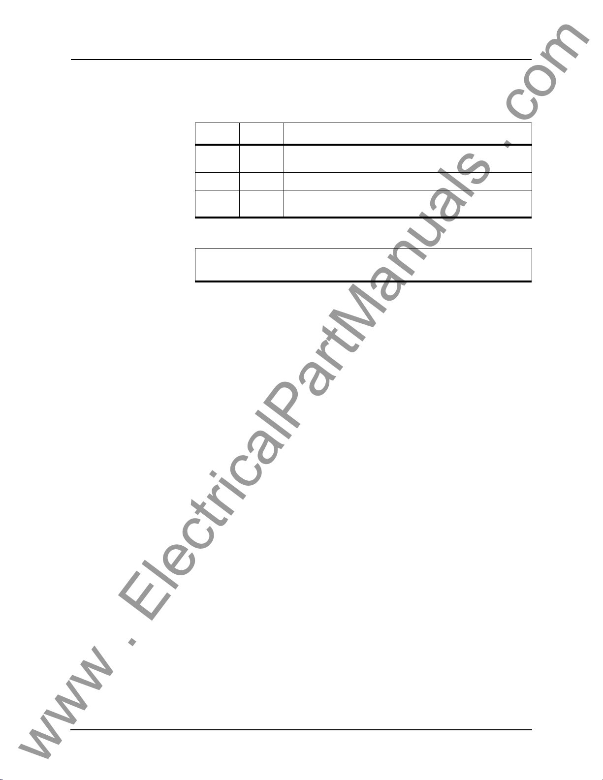
To change the Access Level either login again using the desired access level as
your login name or use the Main Menu>Access menu.
Access Level Allowed actions
view lowest View settings, online readings and logs. List and retrieve records. At
change middle Do all of the above, plus change the settings and delete records.
service highest Do all of the above two categories, plus calibrate the analog inputs,
Service access is only available through a local, front port connection.
Passwords Individual passwords for the view and change ac
prevent or limit remote access to the relay. Passwords are not required for the
service level. This level is only available at the front of the local relay through
serial Port 1.
You can only change the passwords from the service level through the Access
nu minimizing the chance that a password is changed casually and provides
me
a means of resolving situations where a password has been forgotten.
this level you cannot af
manually contro
l output auxiliary relays and modify passwords.
fect the operation of the controller.
cess levels are available to
3-6 B-PRO User Manual 8700 D01908R02.12
Page 37
3 Using the IED (Getting Started)
www . ElectricalPartManuals . com
Terminal Mode Menus
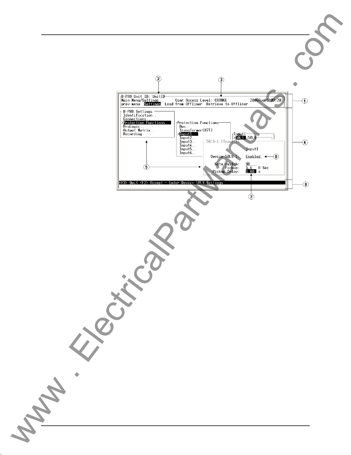
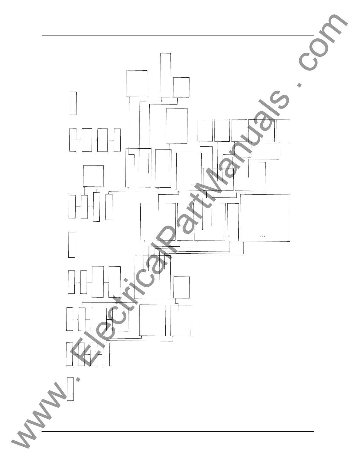
The menu tree consists of a series of sub-menus, which branch off from the
Main Menu For a map of the structure see “Terminal Mode Menus” on page 3-
7. The features of the terminal mode screen are shown in Figure 3.3: "Terminal
Mode Features", and explained below.
Figure 3.3: Terminal Mode Features
1 Main Menu Bar - This is where the menus are accessed. Use the right and
left arrow keys to move the highlight. Items are selected using the <Enter>
key. As a short-cut, use the first letter of the menu item to access it directly.
The <Esc> key will take you back to the previous menu level.
2 Unit ID display - This is where the user-defined unit
3 Access Level display - This is where the
at is displayed.
4 Sub-Menu screen Area - This area is
played to or entered by the user.
5 Sub-Menu screens - There are two types, Intermediate and Data Entry/Dis-
play screens.
a. Intermediate screen - Used to navigate through menu system t
vidual data entry/display screens. Thes
tings>Settings menu. Use the arrow keys to move the
left or right through the screens. Items are selected using the <Enter> key.
Using <F2> and <F3> will get you back to the Main Menu Bar. The difference is that <F2> will save settings and <F3> will
means that there are more sub-menus. If not then the data entry/display
screen for that menu item will be displayed.
b. Data Entry/Display screen - Used to display and/or change data. These
screens
event logs, utility settings, etc. This also includes screens where commands
are made, such as calibration, controlling output contacts, etc. Use the arrow keys to move the highlight up, down, left or right through the screens.
Using <F2> or <F3> at this point
can include a variety of information including settings, record lists,
access level that you are logged in
used when information is being dis-
e screens are only used in the Set-
will take you back to the previous inter-
ID is displayed.
o the indi-
highlight up, down,
not. The ".." after an item
D01908R02.12 B-PRO User Manual 8700 3-7
Page 38
3 Using the IED (Getting Started)
www . ElectricalPartManuals . com
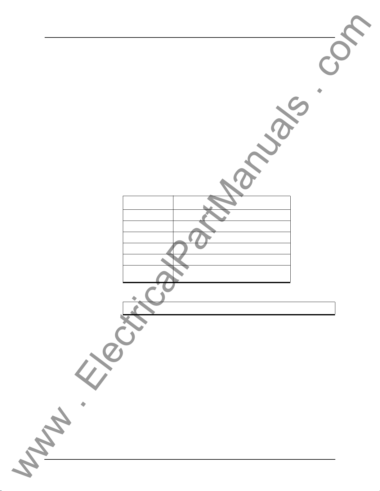
mediate screen. The difference is that <F2> will save the changes that were
made and <F3> will leave the data intact.
In Figure 3.3, the screens with the heading "B-PRO Settings" and "Protection Functions" are examples of intermediate screens and "50LS-1 (Input
1)" is an
6 List - Used in Data Entry/Display screens. To
Ex. Enabled/Disabled. Pressing the <Enter> key toggles forward through
the list and the <Space Bar> toggles backwards through the list. For long
lists such as those found in the ProLogic screen, a drop-down box will appear that displays multiple selections. In this case you
and down arrow keys to scroll through the list. Pressing <u> or <d> will
scroll through the list up or down one page at a time. In all cases, press <F2>
to accept the setting or <F3> to close the box with no changes.
7 Entry Box - Used in Data Entry/Display sc
where appropriate.
8 Status Bar - Provides clues and
Key Function
example of a Data Entry/Display screen
ggles through a list of entries.
can also use the up
reens. Enter text or numbers,
information about entering data.
<F2> Accept or Freeze or Execute
<F3> Quit or Exit
<Esc> Back to previous menu level
<Enter> Select or toggle forward
<Space Bar> Toggle backward
<Up>, <Down>,
t>,<Right>
<Lef
Note: the mouse does not work in VT100 terminal mode.
Moves the highlight in the direction specified by
the key pressed
3-8 B-PRO User Manual 8700 D01908R02.12
Page 39
Quit
S
2
www . ElectricalPartManuals . com
VIEW
Access
Setup
Access
CHANGE
Time
Ports
SCADA
Access
Calibrate
IA1, IB1, IC1-
Password
Maintenance
Calibrate
IA6, IB6, IC6
VA, VB, VC
Outputs
Control Virtual Inputs
Erase
Diagnostics
Output Contacts Toggle
Transfer Diagnostics
1-14
Erase
Records
Modbus
Status Message
Modbus Diagnostic
Modbus Log
Modbus..
Analog Inputs
Voltage Input
Event Log
87B
Current Input1
Current Input6
87B-1
87B-2
Bus
87B..
59
59..
59-1
27..
3 Using the IED (Getting Started)
-
59-2
60
81..
27
Input 1
27-1
27-2
50BF
50LS..
81
81 O/F-1
81 O/F-1
50/51/67
50N/51N/67
46-50/46-51/67
81 U/F-1
81 U/F-2
50LS
50LS-1
50L
Setup
Utilities
Event Log
List
Records
Settings
Settings
Analog
Metering
Diagnostics
Maintenance
Recording
Initiate Fault
Initiate Swing
from
Load
Offliner
I/O
Logic
Recording
to
Offliner
Retrieve
Identification
Relay
Comments
Settings
Identification...
Connections...
Protection Functions..
Analog
87B Operating
87T Operating
Analog Inputs..
External Inputs
Output Contacts
ProLogic
Output Matrix..
Recording
Line Quantities
Analog Inputs
Virtual Inputs
Connections
System Parameters
Protection
Logic 1
Logic 2
Logic
Protection..
ProLogic..
Virtual Inputs..
Output Matrix
#1 (Input1)
#6 (Input6)
#7 (27/59/60/81O/
Protection Functions
Windings/CT
Bus..
Transformer (87T)
Input 1..
Input 6..
ProLogic
ProLogic 1-15
81U/87B/87T
#8 (ProLogic)
#9 (External Inputs)
#10 (Virtual Inputs 1-15)
#11 (Virtual Inputs 16-30)
Id
Figure 3.4: Terminal Mode Menus
D01908R02.12 B-PRO User Manual 8700 3-9
Page 40
3 Using the IED (Getting Started)
www . ElectricalPartManuals . com
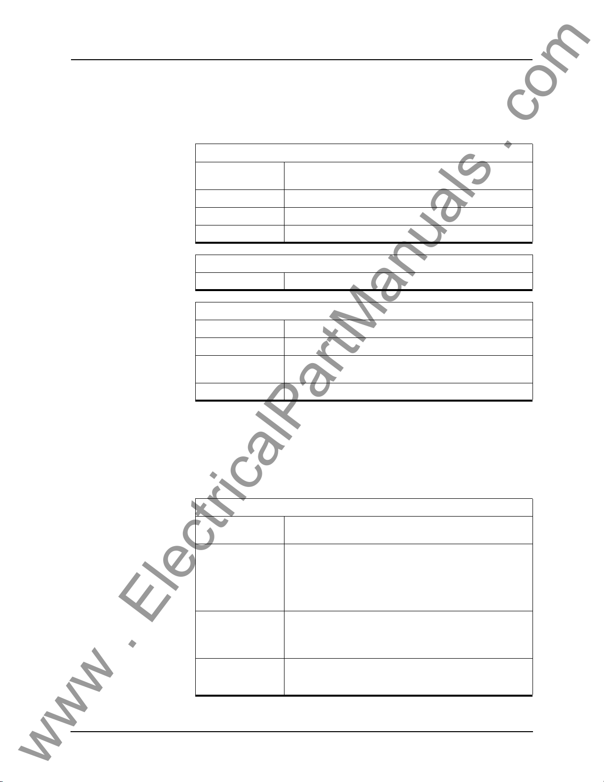
ID Provides the device serial number, software version, required settings version,
nominal system values and external input board rating. There are no user settings here.
Metering Submenus: Analog, I/O, Logic
Analog
87B Operating Provides information about operating and restraint current for 87B-1
and 87B-
87T Operating Provides information about operating and restraint current for 87T.
Line Quantities Provides primary MW and MVAR of each CT input.
Analog Inputs Provides secondary values of the ac analog voltages and currents.
I/O
I/O Displays the state of the external inputs and the output contacts.
Logic
Protection/Logic1 Provides the present status of the internal logic states.
2.
Protection/Logic2 Provides the present status of the internal logic states.
ProLogic Provides the present status of the Pr
level becomes active, its state changes from low to high.
Virtual Inputs Displays the state of the virtual inputs.
oLogic states. When a logic
Settings Submenus: Settings, Load from Offliner, Retrieve to Offliner
Settings
Settings includes all the submenus pertaining to protection functions used to
create a relay setting. When these settings are made or changed, you can load
them into the relay allowing input of all settings information for the relay.
Setting Submenus (Refer to Figure 3.4: "Terminal Mode Menus")
Identification These screens are where relay/station information can be entered,
Connections These menus contain the settings that are used to define the pri-
Protection Functions These menus are used to make the individual settings for the vari-
as well as names for
mary system that is connected to the relay. Settings such as Bus
Base MV
ters screen. The Windings/CT screen cont
ferential zone, CT ratio settings, tr
control.
ous protection devices provided by the relay
above can be broken further into sub menus for the different protective zones available.
A, Nominal Voltage Level are made in the System Parame-
the relay I/O.
ains settings such as dif-
ansformer settings and digital
. Each of the sub menus
ProLogic This where each ProLogic statement that is provided by the relay
can be defined. T
relay, so there are 15 screens.
3-10 B-PRO User Manual 8700 D01908R02.12
here are 15 ProLogic statements available in the
Page 41
3 Using the IED (Getting Started)
www . ElectricalPartManuals . com
Output Matrix This is where the relay’s protection devices, external inputs, virtual
Recording This screen contains the settings for setting the length of
Load From Offliner
You can download the settings file into the relay using the terminal mode
menu.
1 On the Window’s desktop, double-click B-PRO Offl
initial Offliner Settings screen appears.
2 Enter the required settings.
3 Save the settings to a file on your PC.
4 Start the Terminal Mode of B-PRO, login as change or se
the Settings menu and activate Load from Offliner function.
5 Reply Yes to
6 In your terminal program, initiate transfer of
2 above. (For example, with Window’s HyperTerminal, you would select
Transfer, then Send File. Browse to find the file, then select Open and finally, Se
7 When the file has been transferred,
settings loaded and secure” is displayed.
nd.
inputs, and ProLogics can be configured to close output contact(s)
or trigger recordings.
fault and
swing recording.
iner Settings icon. The
rvice, then access
the “Ready to load remote setting.” prompt.
the setting file created in step
verified and loaded, a message “New
A “serial number discrepancy” message may appear. This is to ensure that you are aware of the exact relay to which the settings are
being loade
the terminal mode ID menu item. Type this serial number into the
B-PRO Serial No. box in the Identification tab display area of Of-
fliner Settings. Alte
check box to bypass serial number supervision.
Retrieve To Offliner
To transfer the relay’s current settings to the PC do the following:
1 Navigate to Se
2 Select Ent
3 The relay asks you if you wish to continue. Select Y for yes.
4 The file is sent to the directory d
fer>Receive File.
When using HyperTerminal use Z-modem (no crash recovery), files
are
received and auto incremented.
Records Submenus - List, Fault Recording, Swing Recording.
d. If this happens, check the relay serial number using
rnately you may check the Ignore Serial Number
ttings>Retrieve To Offliner.
er.
efined by the HyperTerminal menu Trans-
D01908R02.12 B-PRO User Manual 8700 3-11
Page 42
3 Using the IED (Getting Started)
www . ElectricalPartManuals . com
Contains the means for initiating and examining recordings.
List Lists all fault records.
Fault Recording Creates one fault record.
Swing Recording Creates one swing record.
Retrieve Records from the Relay
To retrieve records from the relay do the following:
1 Navigate to Records>List and
2 Select Records using the s
to retrieve a record directly.) The record will be saved in the directory specified by the terminal emulation program.
When using HyperTerminal if “Use receiving protocol:” is set to “Z
modem with Crash Recovery”, file transfers are skipped by HyperTerminal if the record already exists in the downloads folder.
When using HyperTerminal use Z-modem (no crash recovery), files
received and auto incremented.
are
press Enter; a records list appears.
pace bar and select R. (You can also press Enter
Delete Records from the Relay
To delete records from the relay do the following:
1 Navigate to Records>List and
2 Select the records for deletion with the space bar and select D. The sele
records will be deleted.
Event Log The event log lists events stored in the relay. While
event list must be manually refreshed in order to display new events. A complete list of the types of events logged is available, for details see “Event Messages” in Appendix D.
If an event triggered a record, then an (R) is displayed by the event.
press Enter.
cted
viewing the Event Log, the
3-12 B-PRO User Manual 8700 D01908R02.12
Page 43
Utilities Sub-menus: Setup, Maintenance, Diagnostics.
www . ElectricalPartManuals . com
Setup
3 Using the IED (Getting Started)
Time Set manual time, IRIG-B skew control. Requires change or
Ports Change Baud rates on communication ports. Requires change or
SCADA Select which SCADA protocol (Modbus or DNP3) to run on the
Maintenance
Calibrate Calibrate all 21 analog ac. Requires service access level.
Outputs Close and open output contacts independent of the associated relay
Control Virtual Inputs Set, reset and pulse virtual inputs. Pulse width is 1 second. Latched
Erase Use submenus Records and Event Logs to erase these records
Diagnostics
Transfer Diagnostics Transfers relay diagnostic file to the PC. The diagnostic file can be
access level.
service acce
SCADA por
as address or timeout. Requires change or service access level.
functio
tual inputs reset after pulse command has executed. Requires
vir
change or service access level.
from
sent to ERLPhase for
ss level.
t. Configure parameters for the selected protocol such
ns. Requires service access level.
the relay memory. Requires change or service access level.
analysis.
service
Modbus Allows Modbus Communications to enter it
low directions on the screen. Programming done using the Modicon
Modbus Proto
by Modicon, Inc., dated November 1994, for details see “Modbus
RTU Communication Protocol” in Appendix E.
col Reference Guide PI-MBUS-300 Rev. G published
Access Submenus: VIEW Access, CHANGE Access, Password.
View Changes the access level to view. Allows you read-only access to
Change Changes the access level to change. Allows you to modify settings
Password Allows you to read and change passwo
Quit Selecting this option ends communication with
relay information.
and delete r
level.
ecords.
rds. Requires service access
the relay.
s Diagnostic Mode. Fol-
D01908R02.12 B-PRO User Manual 8700 3-13
Page 44

3 Using the IED (Getting Started)
www . ElectricalPartManuals . com
Metering Data
Front Panel Metering
TUI Metering The TUI provides the following metering quantiti
The quantities provided on the front panel display include:
• Positive (primary) sequence L-L voltage
• Positive sequence frequency
• Phase to neutral bus voltage
• Inputs 1 to 6 A, B and C phase currents
• P and Q for each input
All quantities are in primary unless otherwise noted.
Analog/87B Operating
Provides the values of IO and IR for both the 87B-1 and 87B-2. It also displays
the enabled/disabled status of the 87B-1 and 87B-2 protection functions. This
screen is useful when testing.
Analog/87T Operating
Provides the values of IO and IR for both the 87T. It also displays the enabled/
disabled status of the 87T protection function. This screen is useful when testing.
Analog/Line Quantities
Displays the P/Q information for each feeder, as well as the positive sequence
L-L voltage and positive sequence frequency. All quantities are in primary values unless otherwise stated.
es.
Analog/Analog Inputs
Displays all secondary values of the voltage and current inputs.
I/O
Displays the status of all external inputs and output contacts.
Logic/ProLogic
Displays the status of all ProLogic.
Logic/Protection/Logic 1
Displays the High/Low status of the 50LS, 50BF, 50/51/67, 50N/51N/67 and
46-50/46-51/67 for each input.
Logic/Protection/Logic 2
Displays the High/Low status of the 87B and 87T tripping/blocking/restraining
functions, also including the 59, 27, 60 alarm, 81 High/Low status.
Logic/Protection/Virtual Inputs
Displays the status of all Virtual Inputs.
3-14 B-PRO User Manual 8700 D01908R02.12
Page 45

4 Protection Functions
www . ElectricalPartManuals . com
Differential Zone Selection and CT Input Assignment
The B-PRO can be configured for a number of different differential zones.
These zones are defined as:
• Bus1
• Bus1 and Transformer
• Transformer Only
• Bus1 and Bus2
Bus1 zone allows up to 6 current inputs
(87B-1). All CT’s used for Bus Protection must be wired in wye.
Bus1 and Transformer zone allows up to 5 current in
zone and 2 inputs for the transformer zone. In this configuration, Input 5 is used
for both the bus zone and the transformer zone. Inputs 1-4 are used for the bus
zone. Input 6 is used for the transformer zone only. Inputs 1-5 must be wired
in wye, but input 6 can be wired in wye or delta.
Transformer Only zone uses inputs 5 and 6 in the transformer
(87T). Input 5 must be wired in wye, but input 6 can be wired in wye or delta.
Bus1 and Bus2 are used where 2 zones o
sired. In this case the maximum number of inputs tha
zone is 4, with the minimum being 2. 87B-1 settings define the first differential
zone and 87B-2 settings define the second.
In all cases, if a CT input will not be used,
nected". This will remove this current input from any differential calculations.
e CT input overcurrent functions and recording are still available.
Th
to be used in the bus differential zone
puts to be used for the bus
f bus differential protection are de-
t can be assigned to one
it should be set to "NC" or "not con-
differential zone
Digital Control
Each CT input can be automatically excluded from all relaying, metering and
recording functions based on the status of an associated external input. To set
this feature, the Digital Control of the CT input must be enabled, the associated
external input selected, and the state of "Exclude When" set. The CT input will
be automatically excluded from all relaying, metering and recording functions
when the status of the associated external input agrees with the "Exclude
When" setting. This feature can be used to automatically adjust the CT inputs
of a differential zone based on the changes in the bus configuration. The connections of "Exclude When" setting accommodates the use of "a" or "b" auxiliary contact as the digital control
input.
Protection Function Descriptions
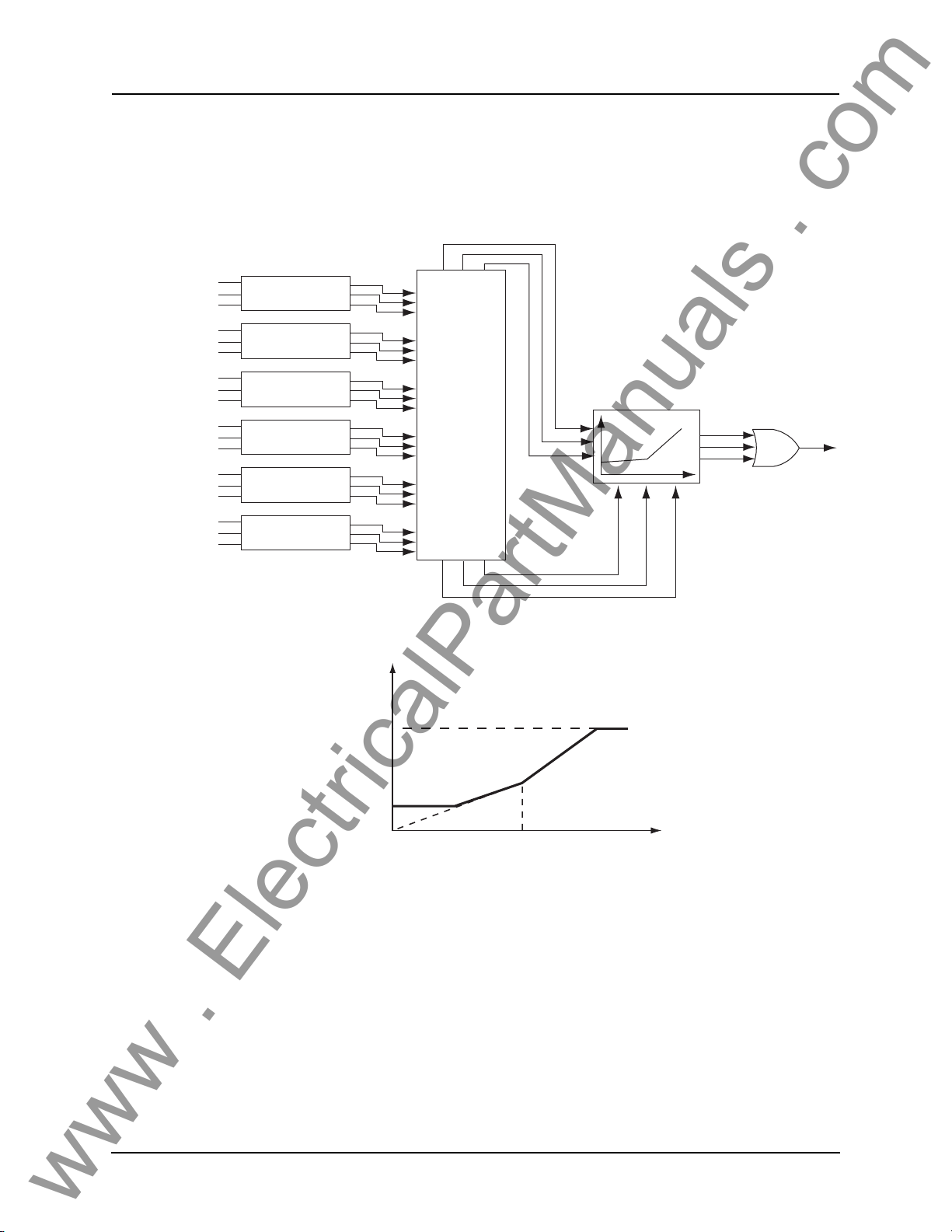
Bus Protection 87B-1 Bus Differential (Bus1 differential zone only)
Device 87B-1 is the main protection of the bus. It will operate for the internal
faults and restraint for the external faults. Up to 6 CT inputs can be configured
as the inputs of 87B-1 and controlled by external inputs. If external control is
D01908R02.12 B-PRO User Manual 8700 4-1
Page 46
4 Protection Functions
www . ElectricalPartManuals . com
enabled, and the corresponding external input is turned on, the ac analog current will be excluded from all relay metering
and recording functions. There is
no harmonic restraint provided for this function. Restraint quantities are
summed; the magnitude sum is then divided by two. Operating quantities are
summed vectors.
I1a
CT Ratio Mismatch
I1b
I1c
I2a
CT Ratio Mismatch
I2b
I2c
I3a
CT Ratio Mismatch
I3b
I3c
I4a
CT Ratio Mismatch
I4b
I4c
I5a
CT Ratio Mismatch
I5b
I5c
I6a
CT Ratio Mismatch
I6b
I6c
Correction
Correction
Correction
Correction
Correction
Correction
Figure 4.1: 87B-1 Bus Differential
IO (pu)
IOH High Setting
Vector Sum
Mag Sum/2
Io = I1+I2+I3+I4+I5+I6
for a, b, and c phases
IR = (|I1|+|I2|+|I3|+|I4|+|I5|+|I6|) / 2
for a, b, and c phases
IO
IOA
IOB
IOC
IRA IRB IRC
IR
Trip A
Trip B
Trip C
S2
IR (pu)
provides immunity to CT mismatch
CT Saturation Detector
Operate Region
IOmin
Figure 4.2: Bus Differential Characteristic
S1
IRs
The B-PRO bus protection includes a significant improvement to the traditional two slope differential characteristic that
and minimal CT saturation sensitivity for external faults. The CT saturation detector detects all CT saturation conditions for external faul
ts and blocks the dif-
fferential protection from operating.
The CT saturation detection and Trip-Bloc
king scheme are composed of two
parts: the first part is to deal with the fast CT saturation, i.e. CT saturates in the
first cycle after the fault occurs; the second part is to deal with the slow CT saturation, i.e. CT saturates after the first cycle.
4-2 B-PRO User Manual 8700 D01908R02.12
Page 47
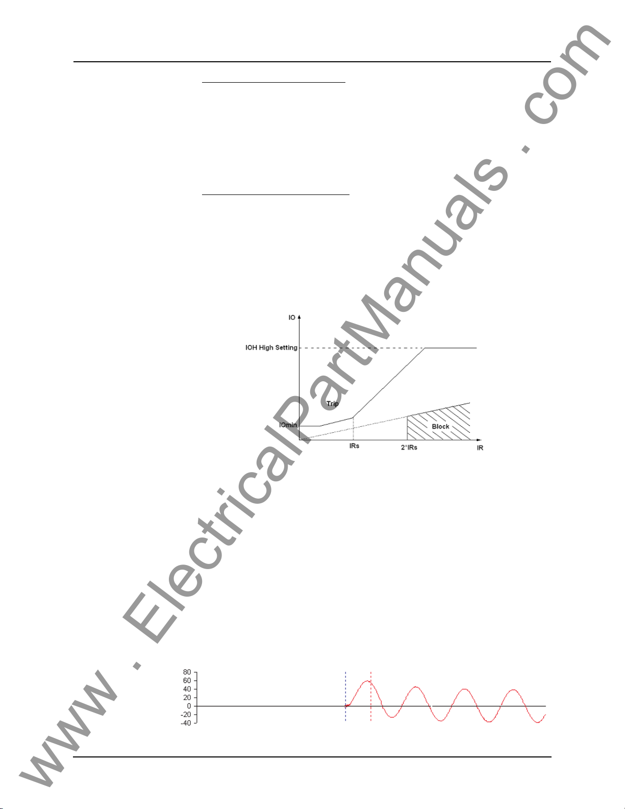
4 Protection Functions
www . ElectricalPartManuals . com
Detection of Fast CT Saturation
Rather than examination of individual line fault currents for the presence of
saturation, the detection method uses only IO and IR for its block/no-block decision. A novel algorithm (patent pending) has been
fast CT saturation quickly, sensitively and accurately. The core of this algorithm is to check the phase relationship of
fault, both IO and IR start to increase simultaneously and they are always kind
of in phase. For an external fault, the phase dIO/dt is always lagging dIR/dt.
Detection of Slow CT Saturation
Sometimes CT does not saturate in the first cycle after the fault occurs due to
the DC offset and the CT core remnant. Under these conditions, the algorithm
described in above "Detection of Fast CT Saturation" could miss the detection
of the changes of IR and IO, because of the limit of the sample window size in
the DFT calculation. A "block zone" under the differential characteristic curve
as shown in Figure 4.3 is defined to solve this.
dIO/dt and dIR/dt. For an internal
developed to detect the
Figure 4.3: Detection of Slow CT Saturation
IRs is the setting parameter, which is normally set to be greater than the maximum bus transfer load. The block level is preset to 2 times of IRs for safety
rgin. The slope in the block zone is preset to 20% for safety margin to cover
ma
the maximum CT mismatch. Whenever the IO, IR trajectory is entered into the
block zone, this algorithm for Slow CT Saturation Detection will set the block
flag to block the differential element from tripping.
The CT saturation detector is simple to use and ca
When enabled, you set a timer to control how long you want an external CT
saturation condition to block the differential protection. Normally you would
set this timer to be slightly longer than your maximum clearing time for an external fault.
D01908R02.12 B-PRO User Manual 8700 4-3
n be enabled or disabled.
Page 48
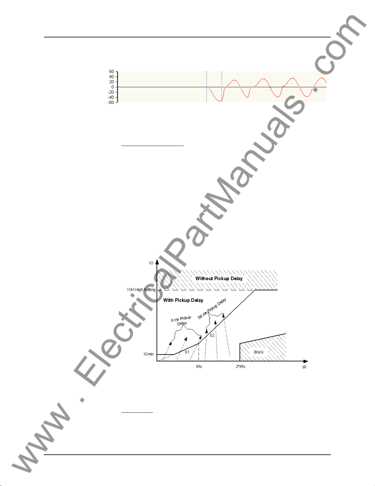
4 Protection Functions
www . ElectricalPartManuals . com
Figure 4.4: External Fault – Fully Offset Source Current
Figure 4.5: External Fault – CT Saturation
Additional Security For additional security, some pickup delays are also applied to the differential
protection function as described below.
IOmin and Slope1 (S1)
As shown in Figure 4.6, when the IO, IR trajectory enters into the trip zone
from IOmin or slope1 region, a 6 ms (8 ms for 50Hz system) pickup delay is
applied so as to be certain that the IO, IR trajectory has reliably come into the
trip zone. To ensure the fast operating speed of 87B function for internal faults,
IRs should be set to be greater than the maximum bus transfer load plus safety
margin. The safety margin should be greater than S1/100 per unit. In this way,
the IO, IR trajectories for internal faults are always entered into the trip zone
from the IOmin and slope1 region rather than from the slope2 region under any
pre-fault conditions.
Figure 4.6: Pickup Delay for Additional Security
Slope2 (S2)
When a slow CT saturation occurs during an external fault as described in page
4-3, the IO, IR trajectory may enter the trip zone, but always from the slope2
region. In most cases when the slow CT saturation occurs, the IO, IR trajectory
4-4 B-PRO User Manual 8700 D01908R02.12
Page 49
4 Protection Functions
www . ElectricalPartManuals . com
will enter into the saturation block zone first so that the block flag will be set
and 87B trip will be blocked accordingly. However, in some special situations
when the fault current contains low AC current combined with high magnitude
slow decaying DC current, the external fault current level may not be high
enough to bring the IO, IR trajectory into the saturation block zone, but it might
still bring the IO, IR trajectory into the trip zone from slope2 region for a short
period of time (the CT recovers to normal quickly). In order to make the relay
secure under these special situations, a 36 ms (45ms for 50Hz system) pickup
delay is applied. As described before, this delay does not affect the operating
speed for internal faults.
IOH High Setting
There is no any intentional delay as long as the IO exceeds the IOH setting
threshold no matter where the IO, IR trajectory comes from. The purpose of the
IOH zone is to clear the extremely severe bus internal faults as soon as possible
IOmin Minimum level that device 87 operates
IRs Point of intersection between slope 1 and slope 2 of the characteristic
S1 Slope of first part of characteristic meetin
S2 Slope of second part of characteristic meeting slope 1
unrestrained setting
IOH High Set Heavy fault trip irrespective of restraint current.
g Io IOmin and slope 2
and high current
The differential relay setting parameters are defined in “Bus Differential Characteristic” on page 4-2, the restraint quantity for the bus differential i
s the sum
of the restraint quantities divided by two.
87B Bus Differential
IOmin (pu)
IRs (pu)
S1 (%)
S2 (%)
0.20 to Min
IOmin
IOmin
Max (S1, 30) to 200.00
IRs S1×
---------------------
100
----------
×
S1
100
----------
×
IRs
1.00,
100
to 50.00
to Min (S2, 100)
High Current Setting (pu)
CT Saturation Detection
CT Sat. Max Block (seconds)
D01908R02.12 B-PRO User Manual 8700 4-5
×
IOmin 3
to 100.00
Enable/disable
0.10 to 99.99
Page 50
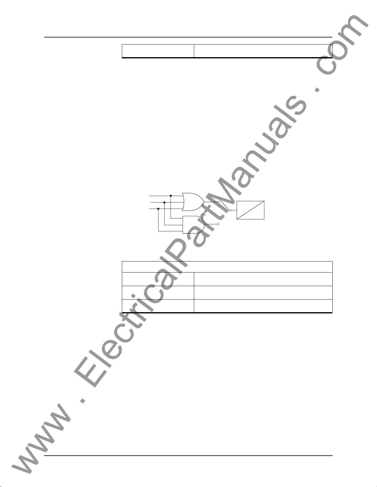
4 Protection Functions
www . ElectricalPartManuals . com
Bus Base MVA
87B-2 Bus Differential
Set in System Parameters
The 87B-2 is used to define the second bus differential zone. The 87B-2 is only
available when the Differential Zone is selected as Bus1 and Bus2. Up to 4 CT
inputs can be assigned to the 87B-2. The 87B-2 settings are the same as the
87B-1.
59 Overvoltage
Two sets of overvoltage protection elements are provided to monitor the bus
voltage. The 59-1 and 59-2 functions are identical in terms of operation. Use
the gate switch to select between an “AND” or an “OR” gate. Use an "AND"
gate to detect 3-phase overvoltage condition; use an "OR" gate to detect any
phase overvoltage condition. The definite time delay can be set to 0.0 for a instantaneous output.
59 Va Main
59 Vb Main
59 Vc Main
Gate Switch (Setting)
OR
AND
T
0
Figure 4.7: 59 Overvoltage
59 Overvoltage
Gate Switch
Pickup (Volts Sec.)
Pickup Delay (seconds)
AND or OR
60.0 to 138.0
0.00 to 99.99
4-6 B-PRO User Manual 8700 D01908R02.12
Page 51
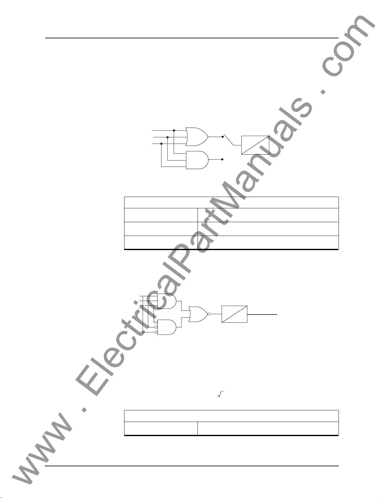
4 Protection Functions
V
V
V
l
www . ElectricalPartManuals . com
27 Undervoltage
Two sets of undervoltage protection elements are provided to monitor the bus
voltage. The 27-1 and 27-2 functions are identical in terms of operation. Use
the gate switch to select between an “AND” or an “OR” gate. Use an "AND"
gate to detect 3-phase undervoltage condition; use an "OR" gate to detect any
phase undervoltage condition. The definite time delay can be set to 0.0 for a
instantaneous output.
Gate Switch (Setting)
27 Va Main
27 Vb Main
27 Vc Main
Figure 4.8: 27 Undervoltage
27 Undervoltage
OR
AND
T
O
Gate Switch
Pickup (Volts Sec.)
Pickup Delay (seconds)
AND or OR
1.0 to 120.0
0.00 to 99.99
60 Loss of Potential
This protection is to detect the loss of potential from either one or two phases,
and issue an alarm.
a Exist
b Exist
c Exist
Figure 4.9: 60 Loss of Potential
AND
AND
10 s
Loss of Potentia
0.0
Where Va_Exist = 1 if Va>0.5 pu, similar for Vb_Exist and Vc_Exist. Pickup
time (= 10.0 seconds) and drop-out time (= 0.0 seconds) are fixed parameters.
1.0 pu is calculated as:
Vpusec
Bus Voltage (Pri)
---------------------------------------------------
=
3x(PT Turns Ratio)
60 Loss of Potential
Pickup Delay
D01908R02.12 B-PRO User Manual 8700 4-7
10 seconds (fixed)
Page 52
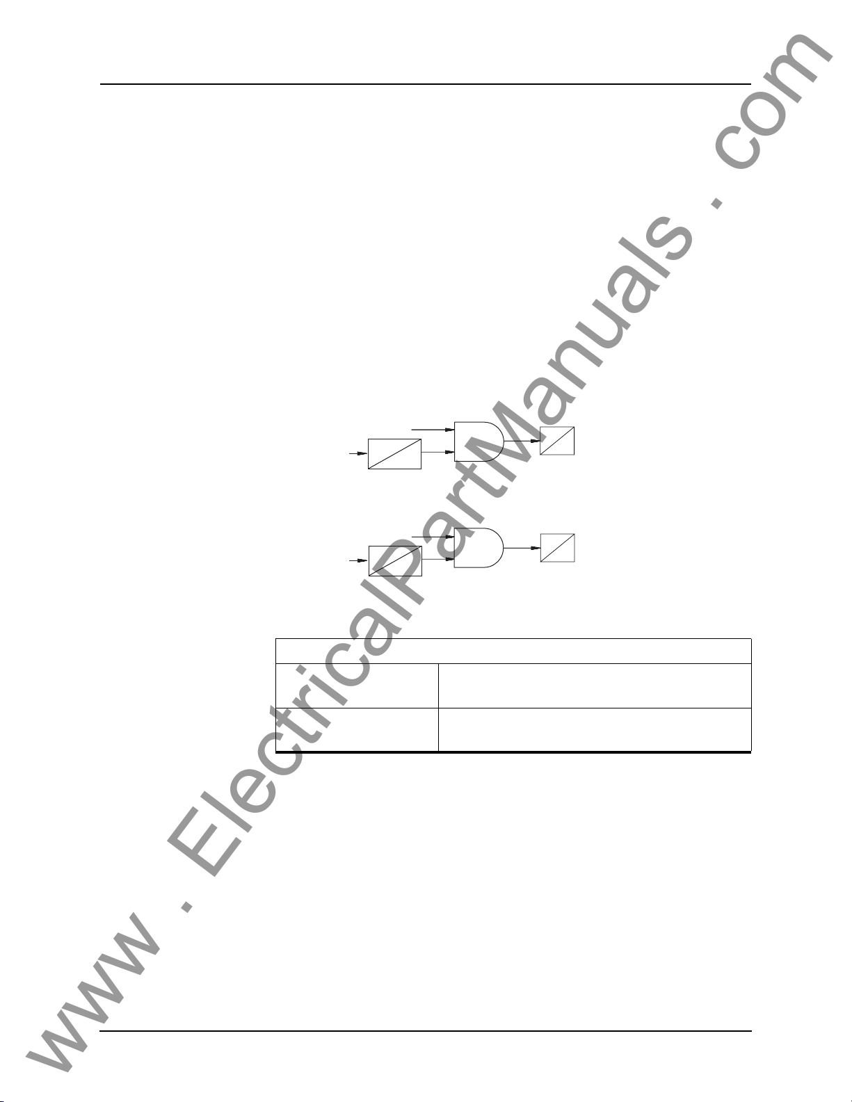
4 Protection Functions
www . ElectricalPartManuals . com
81 Over/Under Frequency
The relay provides two sets of over frequency protection elements to monitor
the bus frequency. The 81 O/F-1 and 81 O/F-2 functions are identical in terms
of operation. Any positive sequence overfrequency condition produces an output. Undervoltage inhibit is provided and fixe
d at 0.25 pu of nominal system
voltage.
The relay provides two sets of under frequency protection element
s to monitor
the bus frequency. The 81 U/F-1 and 81 U/F-2 functions are identical in terms
of operation. Any positive sequence underfrequency condition produces an
output. Undervoltage inhibit is provided and fixed at 0.25 pu of nominal system voltage.
The 81 frequency elements operate and prod
uce an output using a definite time
delay function. The overall time delay will be the user setting, an additional inherent delay from 1.25 cycles to 1.75 cycles,
and an additional +- 3 ms operate
time for the output contact. The element will have a total operate time of under
5 cycles when set to the minimum time delay setting of 0.05 seconds.
81 O/F Freq.
Vpos > 0.25 P
Figure 4.10: 81 O/F Over Frequency
Vpos > 0.25 P
Figure 4.11: 81 U/F Under Frequency
81 Over/Under Frequency
Pickup (Hz)
Pickup Delay (seconds)
200 ms
0
81 U/F Freq.
200 ms
0
60.0 to70.0 / 50.0 to 60.0 (60 Hz)
50.0 to 60.0 / 40.0 to 50.0 (50 Hz)
0.05 to 99.99 (inherent delay of 1.25 to 1.75 cycles,
depend
T
0
T
0
ing on frequency step change)
4-8 B-PRO User Manual 8700 D01908R02.12
Page 53
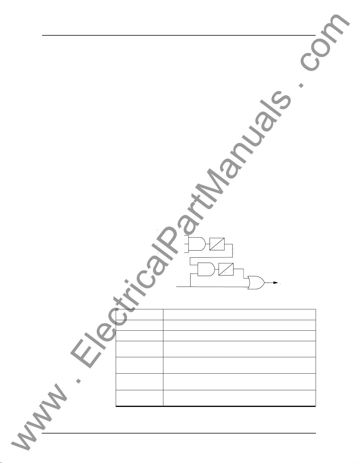
4 Protection Functions
www . ElectricalPartManuals . com
Transformer Protection
87T Transformer Differential
Device 87T is the differential protection for the transformer zone. It can be
used when the differential zone is selected as Bus1 & Transformer or Transformer Only. The device operates for internal faults and provides restraint
for
external faults, transformer energization or transformer over excitation conditions. CT input 5 and CT input 6 are dedicated for the differential device when
2 differential
zones (bus and transformer) are selected, or if only 1 differential
zone (transformer) is selected. If external control is enabled, and asserted, the
ac analog current will be excluded from all relay, metering and recording functions.
Restraint quantities are summed;
the magnitude sum is then divided by two.
Operating quantities are summed vectors.
Device 87T has 2nd and 5th harmonic blocking, each element is set independent of each other. If an input phase current is less
than 5% of I nominal, this
current will not be used for the 2nd and 5th harmonic blocking calculation. For
a 5A relay this equals 0.25A.
As shown below, the 2nd harmonics restraint si
gnal is stretched for 5ms in the
first cycle on transformer energization to prevent the 2nd harmonics restraint
signal from any possible momentary reset due to the current signal transition
in the first cycle. Note that this logic only becomes active when the transformer
has been de-energized or very lightly loaded (the restraint current is less than
30% of IOmin setting)
Device 37: under-curr ent
37 IRA (30% of IOmin)
37 IRB (30% of IOmin)
37 IRC (30% of IOmin)
2nd Harmonics Restraint Si gnal
IOmin Minimum level that device 87 operates
IRs Point of intersection between slope 1 and slope 2 of the characteristic
S1 Slope of first part of characteristic meetin
S2 Slope of second part of characteristic meeting slope 1
unrestrained setting
I2 Ratio of 2nd harmonic current to fundamental, used to provide energiz-
ing harmonic restraint
I5 Ratio of 5th harmonic current to fundamental, used to provide restraint
on over e
IOH High Set Unrestrained high set overcurrent, operates if a heavy fault occurs on
the tr
xcitation
ansformer irrespective of restraint
10 s
17 ms
0
Transformer has
been de-energized
5 ms
Block 87
g IO min and slope 2
and high current
D01908R02.12 B-PRO User Manual 8700 4-9
Page 54
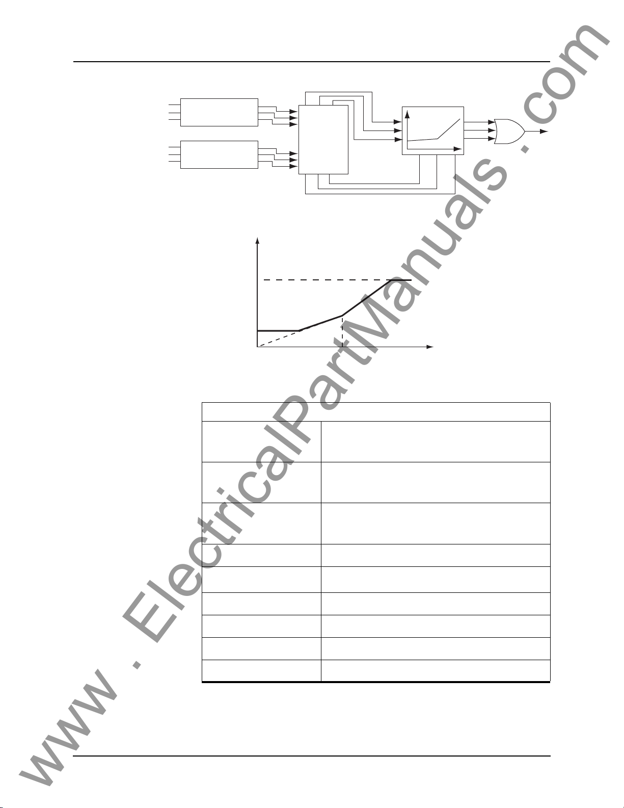
4 Protection Functions
www . ElectricalPartManuals . com
I5a
I5b
I5c
I6a
I6b
I6c
Y/∆ Transformation
and CT Ratio Mismatch
Y/∆ Transformation
and CT Ratio Mismatch
Correction
Correction
Vector Sum
Mag Sum/2
IOA
IOB
IOC
IO
IRA IRB IRC
Figure 4.12: 87T Transformer Differential
IO (pu)
IOH High Setting
S2
IR (pu)
IOmin
Operate Region
S1
IRs
Figure 4.13: Transformer Differential Protection Characteristic
IR
Trip A
Trip B
Trip C
87T Transformer Differential
IOmin (pu)
IRs (pu)
S1 (%)
S2 (%)
High Current Setting (pu)
I_2nd/I_fund Ratio
I_5th Restraint Enabled
I_5th/I_fund Ratio
Transformer Base MVA
IRs S1×
---------------------
0.2 to
100
IOmin
IOmin
Max (S1, 30) to 200.00
IOmin 3
to 100.00
0.05 to 1.00
Enable/disable
0.05 to 1.00
Set in Winding/CT Connections
100
----------
×
to 50.00
S1
100
----------
×
to Min (S2, 100)
IRs
×
4-10 B-PRO User Manual 8700 D01908R02.12
Page 55
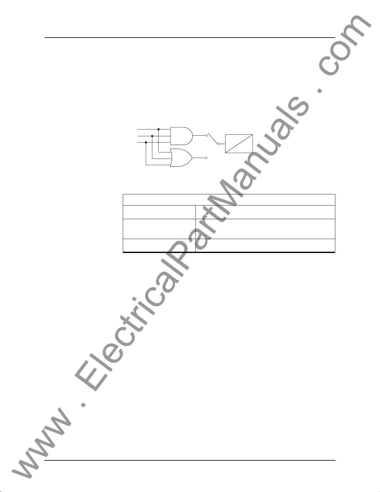
4 Protection Functions
www . ElectricalPartManuals . com
Inputs 1 to 6 Protection
50LS Low Set
Two sets of definite time delay overcurrent protection functions on each CT input provide non-directional current detection. The 50LS-1 and 50LS-2 functions are identical in terms of operation. Us
e the gate switch to select between
an “AND” gate or an “OR” gate. Use an "AND" gate to detect 3-phase overcurrent condition; use an "OR" gate to detect any phase overcurrent condition.
e definite time delay can be set to 0.0 for a instantaneous output.
Th
Gate Switch (Setting)
50 Ia
50 Ib
50 Ic
Figure 4.14: 50LS Low Set
50LS Low Set Overcurrent
Gate Switch
Pickup (Amps Sec.)
AND
OR
T
O
AND or OR
0.1 to 50.0 (5A)
0.02 to 10.00 (1A)
Pickup Delay (seconds)
0.00 to 99.99
D01908R02.12 B-PRO User Manual 8700 4-11
Page 56
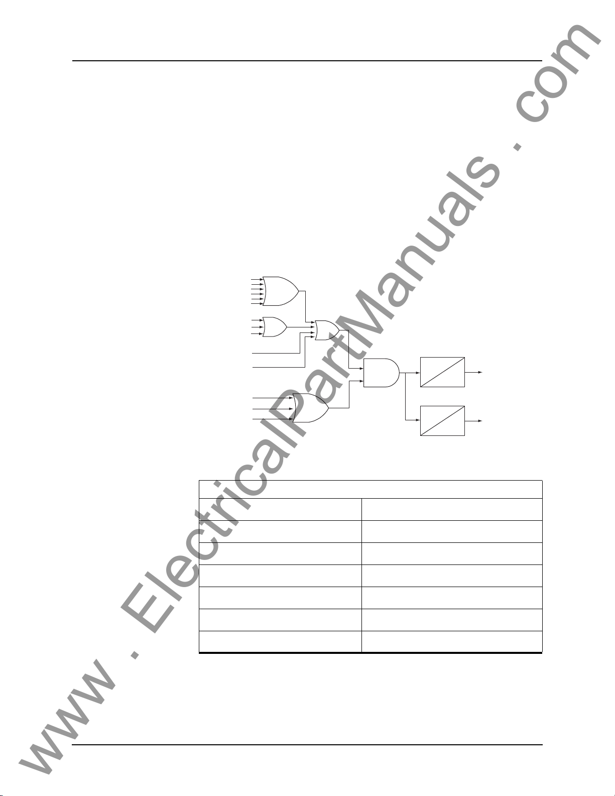
4 Protection Functions
www . ElectricalPartManuals . com
50BF Breaker Failure
Breaker failure protection function is used to detect breaker failures and react
correspondingly. This function is provided on all the current inputs. When
breaker failure is initiated by a trip (user-settable: include 87B-1, 87B-2, 87T,
ProLogic, External Input or its own O/C functions) and the breaker current still
exists, two timers (T1 and T2, user settable) will be started. After these timers
are timed out, if the current still exists (which indicates breaker failure), the
output of this function will be set high.
The two outputs of this function can be used to
trip another trip coil or the next
level of breakers, such as bus breakers. For example set T1 to 10 ms and T2 to
200 ms, and then use the output of T1 to send a trip to the associated circuit
breaker before sending the output of T2 to the bus or transformer protection. If
the output of T1 tripped the circuit breaker before T2 timed out the current input would dropout and you would not clear the whole transformer or bus zone.
50 Trip
51 Trip
50N Trip
51N Trip
50/46 Trip
51/46 Trip
87B-1 Trip
87T Trip
87B-2 Trip
ProLogic (1-15)
External Input (1-9)
50 Ia (0.04 In)
50 Ib (0.04 In)
50 Ic (0.04 In)
Figure 4.15: 50BF Breaker Failure
50BF Breaker Fail
Breaker Failure Initiated by 87B-1
Breaker Failure Initiated by 87B-2
Breaker Failure Initiated by 87T
Breaker Failure Initiated by ProLogic
Breaker Failure Initiated by External Input
Pickup Delay 1 (seconds)
Pickup Delay 2 (seconds)
T1
0
T2
0
Enable/disable
Enable/disable
Enable/disable
ProLogic 1 to ProLogic 15
External Input 1 to External Input 9
0.01 to 99.99
0.01 to 99.99
Output1
Output2
4-12 B-PRO User Manual 8700 D01908R02.12
Page 57
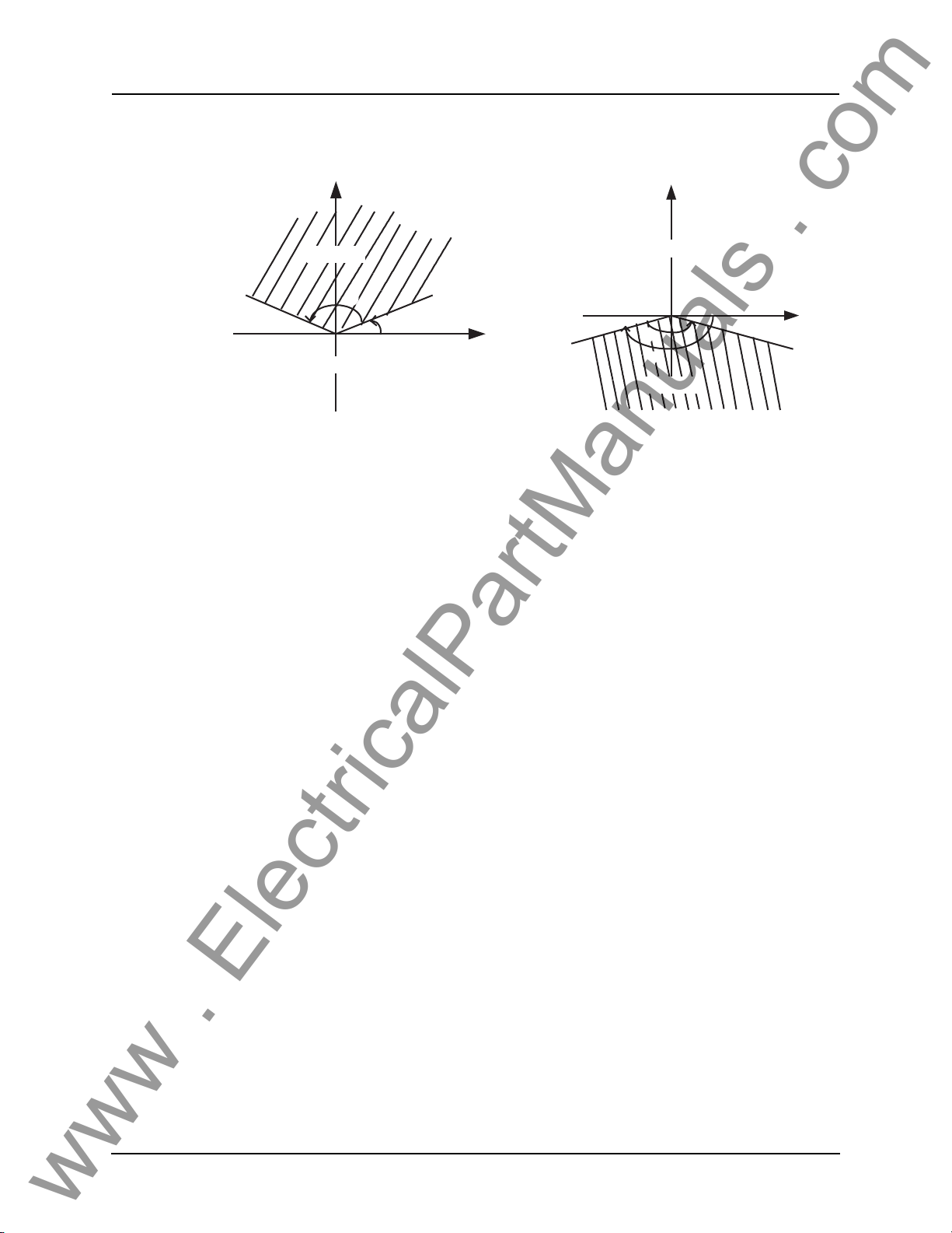
67 Directional Element
www . ElectricalPartManuals . com
4 Protection Functions
End Angle
jx
Forward
β
α
Reverse
Case 1: 0° < α < 180° Case 2: -180° < α < 0°
Figure 4.16: 67 Directional Element
Start Angle
R
Start Angle
jx
Reverse
β
α
Forward
Two user-defined parameters, Alpha (-179.9° to 180.0°) and Beta (0.1° to
360.0°), set in the system parameters setting area, define the directional element where Alpha is the start angle and Beta is the angle range (always positive), i.e. the end angle is Alpha + Beta. The forward direction is def
ined in the
region where the line originates, the start angle, and rotates anti-clockwise
completing at the end angle. for details see Figure 4.16:
67 Directional Element
on page 4-13 illustrates the definition of the directional element. You can
ibly define the forward trip region by setting Alpha
and Beta properly based on
your needs.
When Beta is set to 360° the forward trip
region becomes the whole complex
range (R + jx), making the element fully non-directional, i.e. the fault is always
declared as a forward fault even if the actual fault is not a forward fault.
Positive sequence memory voltage (VposMem) and positi
ve sequence current
(Ipos) are used to decide the directionality of the fault, i.e. if the calculated positive sequence impedance through VposMem
and Ipos falls into the forward
trip region as shown above, the fault is declared as a forward fault.
R
End Angle
flex-
D01908R02.12 B-PRO User Manual 8700 4-13
Page 58
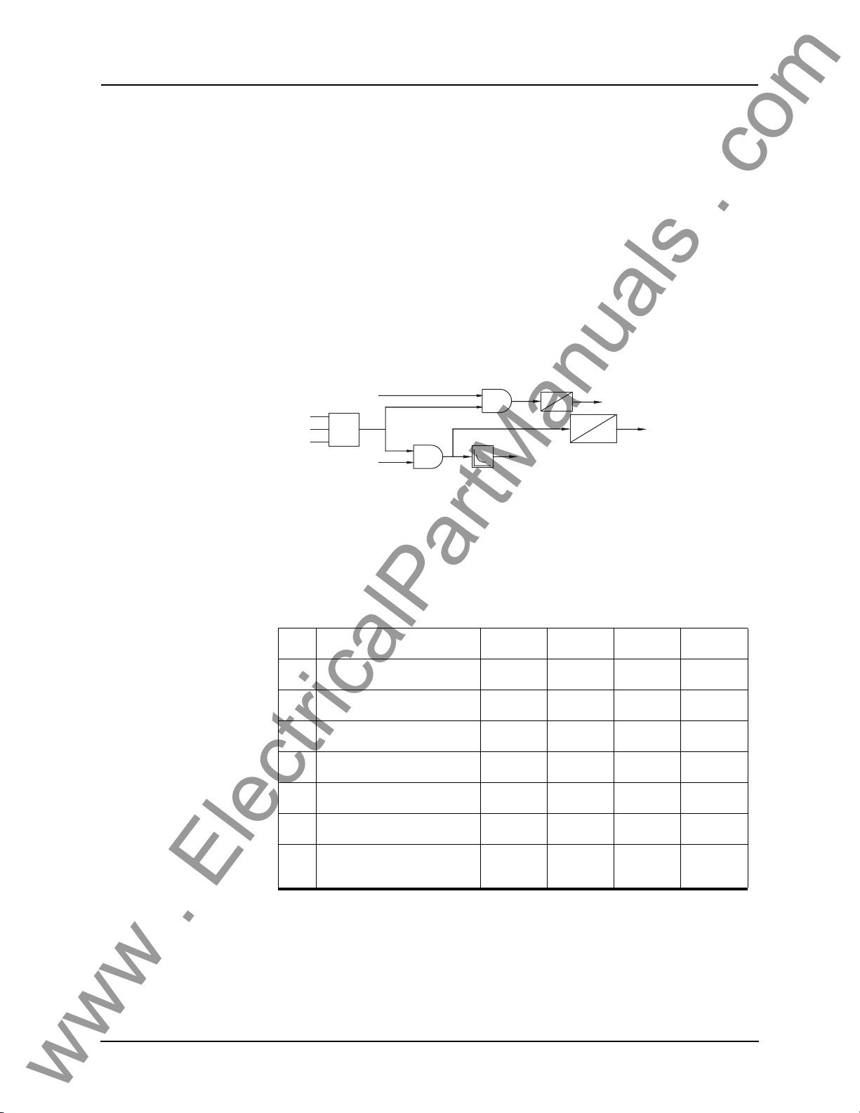
4 Protection Functions
www . ElectricalPartManuals . com
50/51/67 Phase Overcurrent
Phase overcurrent provides backup protection to the differential protection.
This function operates on fundamental quantities of the highest phase current
of the 3 phases. Two sets of phase time overcurrent protection functions on
each CT input provide directional or non-directional current detection. There
is a definite time overcurrent element (50) and an inverse time overcurrent element (51). You can configure both 50 and 51 to be non-directional, forward
direction, or reverse direct
ion sensitive. You can also configure both 50 and 51
outputs to initiate the 50BF protection element. Device 51 provides three predefined IEEE, three IEC inverse time curve
s, and one user-defined curve. The
equation and the parameters of device 51 are listed below. You can select the
user-defined curve type and the parameters in the equation are settable otherwise they are fixed and determined by the curve
T = 10 ms or setting whichever
Directional element
1A
Max
1B
1C
Directional element
50/51 Over Current for Input 1
Figure 4.17: 50/51/67 Phase Overcurrent
is greater if it's directional.
Timer is active only
51
if it's directional.
type.
50
T
0
10ms
51 Pickup
Alarm
0
When the threshold for pickup of the relay is exceeded, the function 51 alarm
will pickup indicating the relay has commenced timing.
Table 4.1: IEC and IEEE Curves
#
Characteristic A B p tr
1
IEC Standard Inverse 0.14 0 0.02 13.5
2
IEC Very Inverse 13.5 0 1.0 47.3
3
IEC Extremely Inverse 80.0 0 2.0 80.0
4
IEEE Moderately Inverse 0.0103 0.0228 0.02 0.97
5
IEEE Very Inverse 3.922 0.0982 2.0 4.32
6
IEEE Extremely Inverse 5.64 0.0243 2.0 5.82
7 User-defined
0.0010 to
1000.0
0.0000 to
10.000
0.01 to
10.0
0.10 to
0.00
10
4-14 B-PRO User Manual 8700 D01908R02.12
Page 59
Pickup: For I > Pickup
www . ElectricalPartManuals . com
TI() TMS B
=
+
Reset: For I < Pickup
TI()
50/51/67 Phase Overcurrent
TR
-----------------------------------
I
------------------
Pickup
-----------------------------------
2
A
I
------------------
Pickup
TMS=
p
1–
1–
4 Protection Functions
Directional
Pickup
Pickup Delay
50 Breaker Failure Initiated
51 Enabled
Directional
Pickup
Curve Type
TMS
A
B
ρ
non-directional, forward, reverse
0.5 to 50.0 (5A)
0.1 to 10.0 (1A)
0.00 to 99.99
enabled or disabled
enabled or disabled
non-directional, forward, reverse
0.5 to 50.0 (5A)
0.1 to 10.0 (1A)
For details see Table 4.1: IEC and IEEE Curves on page 4-
14.
0.01 to 10.00
0.0010 to 1000.0000
0.0000 to 10.0000
0.01 to 10.00
TR
51 Breaker Failure Initiated
D01908R02.12 B-PRO User Manual 8700 4-15
0.01 to 100.00
enabled or disabled
Page 60

4 Protection Functions
www . ElectricalPartManuals . com
50N/51N/67 Neutral Overcurrent
Neutral Overcurrent provides protection for phase to ground faults. This function operates fundamental 3I
0 quantities. Two sets of neutral time overcurrent
protection functions on each CT input provide directional or non-directional
current detection. There is a definite time overcurrent element (50N) and an inverse time overcurrent element (51N). Yo
u can configure both 50N and 51N
to be non-directional, forward direction, or reverse direction sensitive. You can
also configure both 50N and 51N outputs to initiate the 50BF protection element. Device 51N provides three predefined IEEE,
three IEC inverse time
curves, and one user-defined curve. The equation and the parameters of device
51N are listed below. You can select the user-defined curve type and the parameters in the equation are settable otherwis
e they are fixed and determined
by the curve type.
50N/51N/67 Neutral Overcurrent
Directional
Pickup
Pickup Delay
50N Breaker Failure Initiated
Directional
Pickup
Curve Type
TMS
A
B
ρ
TR
non-directional, forward, reverse
0.5 to 50.0 (5A)
0.1 to 10.0 (1A)
0.00 to 99.99
enabled or disabled
non-directional, forward, reverse
0.5 to 50.0 (5A)
0.1 to 10.0 (1A)
For details see Table 4.1: IEC and IEEE Curves on page 4-
14.
0.01 to 10.00
0.0010 to 1000.0000
0.0000 to 10.0000
0.01 to 10.00
0.01 to 100.00
51N Breaker Failure Initiated
enabled or disabled
Pickup: For I > Pickup
-----------------------------------
=
TI() TMS B
4-16 B-PRO User Manual 8700 D01908R02.12
+
A
3Io
------------------
Pickup
p
1–
Page 61

Reset: For I < Pickup
www . ElectricalPartManuals . com
TI()
TR
----------------------------------3Io
------------------
Pickup
4 Protection Functions
TMS=
2
1–
D01908R02.12 B-PRO User Manual 8700 4-17
Page 62
4 Protection Functions
www . ElectricalPartManuals . com
46-50/46-51/67 Negative Sequence Overcurrent
Negative Sequence Overcurrent provides further protection for any unbalanced faults. This function operates fundamental I
ative sequence time overcurrent protection functions on each CT
2 quantities. Two sets of neg-
input provide
directional or non-directional current detection. There is a definite time overcurrent element (46-50) and an inverse
time overcurrent element (46-51). You
can configure both 46-50 and 46-51 to be non-directional, forward direction,
or reverse direction sensitive. You can also configure both 46-50 and 46-51
outputs to initiate the 50BF protection element. Device 46-51 provides three
predefined IEEE, three IEC inverse time curves, and one user-defined curve.
The equation and the parameters of device 46-51 are listed below. You can select the user-defined curve type and the parameters in the
equation are settable
otherwise they are fixed and determined by the curve type.
46-50/46-51/67 Negative Sequence Overcurrent
Directional
Pickup
Pickup Delay
46-50 Breaker Failure
Initiated
Directional
Pickup
Curve Type
TMS
A
B
ρ
TR
non-directional, forward, reverse
0.5 to 50.0 (5A)
0.1 to 10.0 (1A)
0.00 to 99.99
enabled or disabled
non-directional, forward, reverse
0.5 to 50.0 (5A)
0.1 to 10.0 (1A)
For details see Table 4.1: IEC and IEEE Curves on page 4-
14.
0.01 to 10.00
0.0010 to 1000.0000
0.0000 to 10.0000
0.01 to 10.00
0.01 to 100.00
46-51 Breaker Failure
Initiated
enabled or disabled
Pickup: For I > Pickup
-----------------------------------
=
TI() TMS B(
4-18 B-PRO User Manual 8700 D01908R02.12
+
A
I2
------------------
Pickup
p
1–
Page 63

Reset: For I < Pickup
www . ElectricalPartManuals . com
TI()
TR
----------------------------------I2
------------------
Pickup
4 Protection Functions
TMS=
2
1–
D01908R02.12 B-PRO User Manual 8700 4-19
Page 64
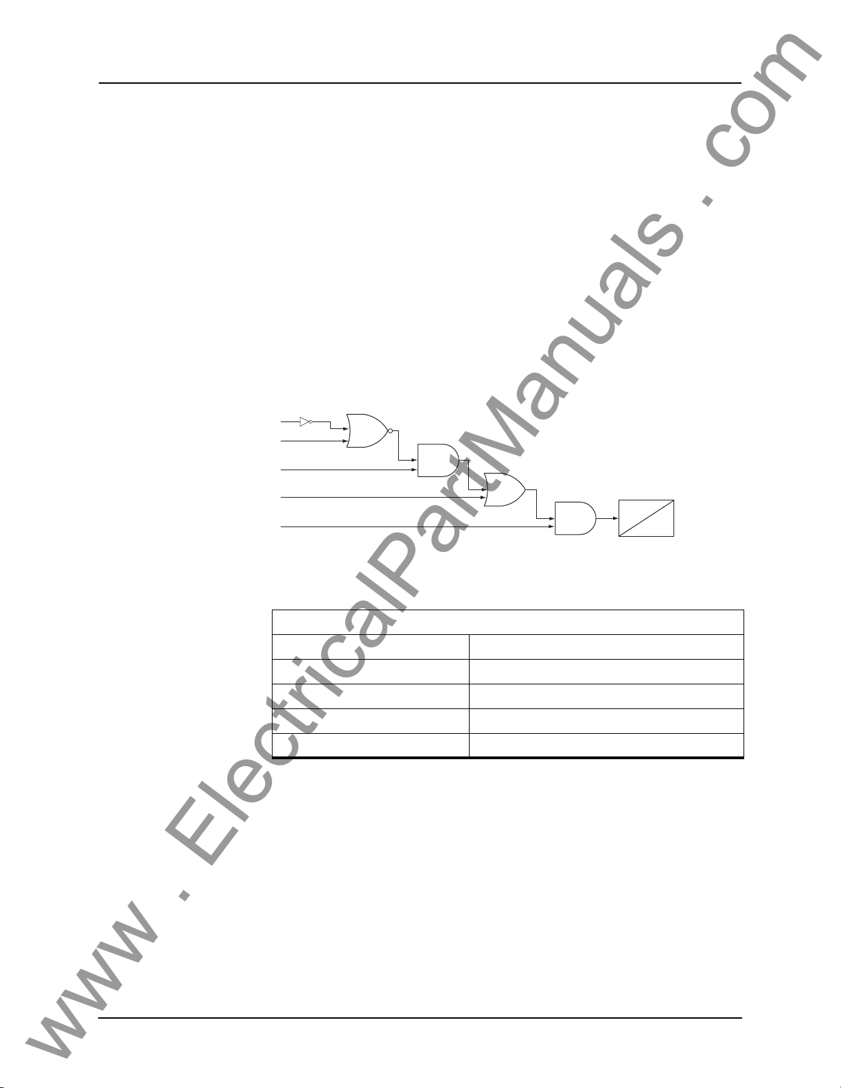
4 Protection Functions
www . ElectricalPartManuals . com
ProLogic The ProLogic control statements are used to create Boolean-like logic. The B-
PRO can use any of the protection functions, external inputs or virtual inputs
combined with logic gates to create a ProLogic control statement. The output
of a ProLogic statement can be nested in another ProLogic statement, so long
as the ProLogic output that is to be nested is of lower order than the one in
which it is to be nested. For example, ProLogic 5 can be used in ProLogic 7 but
not vice-versa.
The possible gates are AND, NAND, OR, NOR, XOR, XNOR, and LATCH.
e control can be time delay pickup and or time delay dropout, and can drive
Th
the front panel target LED. 15 ProLogic control statements outputs are available and can be used in the output matrix to customize the relay
to your specific
needs. Inputs to ProLogic can be all the elements, previous ProLogic statements for logic nesting usage, as well as
The example shows A to E inputs are status
lectable. Each ProLogic output can be give
External and Virtual Inputs.
points of devices that are user-se-
n a specific name, pickup and rest
time delay.
A
B
C
D
E
Figure 4.18: ProLogic
ProLogic Setting Functions
Name Give the ProLogic a meaningful name
Pickup Delay Delay time from pickup to operate
Dropout Delay Delay time from dropout to a ProLogic status of low
A, B, C, D, E Relay elements as input statements
Operators Boolean-type logic gates
P/U
D/O
4-20 B-PRO User Manual 8700 D01908R02.12
Page 65

Recording Functions
www . ElectricalPartManuals . com
The relay has recording and logging functions to aid with the analysis of faults,
and the overall performance of your protection scheme.
4 Protection Functions
Fault Recording The relay provides DFR-quality fault recording, capturi
forms and external input states at a rate of 96 sa
also contains the timing of the internal logic produced by the relay (e.g. Device
87B-1 trip). Obtain this information by uploading the records from the relay
via the terminal mode file transfer process and view them with RecordBase
View software.
The quantities recorded are:
• 21 analog channels (3 voltages an
peres respectively) @ 96 samples/cycle
• 9 operational currents and 9 restra
87B-2, 87T IO+IR)
• 9 external inputs @ 96 samples/cycle
• relay internal logic signals @ 8 sa
• 15 ProLogic signals @ 8 samples/cycle.
Parameters that are user-selectable with respect t
• Record length (0.2–2.0 seconds => 12 – 120 cycles @
automatic extension to capture successive triggers
• Recorder triggering by any internal logic or
Swing Recording The B-PRO records dynamic system response
stability and to provide a larger context for fault analysis. Swing records contain positive sequence phasor measurements and system frequency
at a rate of 1 phasor per cycle. Swing records can extend to 3 minutes in duration.
The quantities recorded are:
• Positive sequence impedance (magni
• Positive sequence voltage (magnitude)
• Positive sequence current (magnitude)
• 3-Phase Vars (reactive power)
• 3-Phase Watts (real power)
• Positive sequence frequency
d 18 currents, in secondary volts and am-
int currents @ 8 samples/cycle (87B-1,
mples/cycle, including virtual inputs
mples per cycle. Each record
o recording faults:
external input signal
s allowing you to analyze system
tude)
ng input signal wave-
60 Hz Base) with
calculated
Record Initiation Recording can be initiated automat
condition is detected. You can set the relay to initiate a fault record on activation of any of its trip or alarm functions or on assertion of any external inputs.
The assignment of fault record
through the relay’s Output Matrix settings.
A recording can also be initiated manually through the t
The commands Fault Recording and Swing Recording are available under the
Records menu.
D01908R02.12 B-PRO User Manual 8700 4-21
ically by the relay when a fault or abnormal
initiation to the various relay functions is done
erminal user interface.
Page 66

4 Protection Functions
www . ElectricalPartManuals . com
A swing record can take a couple of minutes to produce due to the
lo
ng post-trigger time.
Record Duration and Extension
Record Storage The B-PRO compresses records on the fly, a
The length of each record is determined by the Record Length setting. Fault
record lengths can be set between 0.2 and 2.0 seconds; swing record lengths
can be set between 30 and 120 seconds. Pre-trigger times are fixed at 10 cycles
for fault records and 30 seconds for swing records and are included as part of
the normal record length.
The B-PRO automatically extends a record as
triggers that are close together. If a trigger occurs while a recording is in
progress, the record is stretched to include the full post-trigger time of subsequent triggers, up to a maximum length—2.0 seconds for fault records; 180
onds for swing records. If a trigger occurs before the end of a record caused
sec
by a previous trigger, but too late to allow sufficient post-trigger time in a maximum extended record, a new overla
The normal record lengths settings
of the relay settings, and can be set from either the terminal user interface or
the Offliner Settings software.
pression rate of 4:1. As a result, the B-PRO can store up to 30 s
recordings and up to 24 minutes of swing recordings in non-volatile storage. If
the storage is full, new records automatically overwrite the oldest, ensuring
that the recording function is always available.
pping record is created.
are accessible under the Recording heading
required to capture consecutive
chieving a typical lossless com-
econds of fault
Record Retrieval
d Deletion
an
A listing of stored records is available through the terminal user interface under
the Records>List menu. The listing transfers records to a connected PC and de-
letes them from storage.
Example:
BPRO-8700-010306-04-2002-05-15 13.17.16.000(Fault)
Records are named by combining the Unit ID setting with the date and time of
initiating record trigger. The record list shows the record type (fault).
the
To delete a record from storage, use the up/down cursor
record, then select <D>. You can also do group deleting and group transferring.
To select multiple records:
1 Select a record.
2 Press the space bar, a asterisk appears to the left of the record
is selected.
3 Continue selecting and pressing the space bar until
selected.
4 Select <D>. A me
and the files are deleted.
To transfer a record to your PC, use the up/down cursor
record, then select r. The record is automatically transferred to your PC using
ssage asks “Delete all selected files?”. Select Y for Yes
keys to select the
to indicate it
all desired records are
keys to select the
4-22 B-PRO User Manual 8700 D01908R02.12
Page 67

4 Protection Functions
www . ElectricalPartManuals . com
the PC terminal program’s z-modem file transfer protocol. The record is placed
in your terminal program’s default to receive the directory which was set before transfer to. (e.g. Windows HyperTerminal’
through the its Transfer menu). When transferred, the record name remains unchanged and the file extension indicat
When the transfer has taken place, you can delete the record or leave a copy on
the relay.
es the record type: “.bpr” for transient.
s default receive directory is set
D01908R02.12 B-PRO User Manual 8700 4-23
Page 68
4 Protection Functions
www . ElectricalPartManuals . com
Event Log
The relay maintains a log of events in a 250 entry circular log. Each entry contains the time of the event plus an
Logged events include trips, alarms, external input a
events such as setting changes. Phase information is included in event messages where appropriate. For example, the event log entry for
be:
2000 Nov 21, 15:34:19.832: 51 on ABC Trip
The event log can be viewed in three ways:
Front Panel The front panel display shows events in abbreviated form
(Trip and Alarm events only).
event description.
ssertions plus internal
a device trip might
Terminal User Interface The full event log is available through the Event Log menu of
SCADA The protocols included in the B-PRO allow all the SCADA
minal user interface.
the ter
master access to the
Alarm events only).
event data from the relay (Trip and
4-24 B-PRO User Manual 8700 D01908R02.12
Page 69
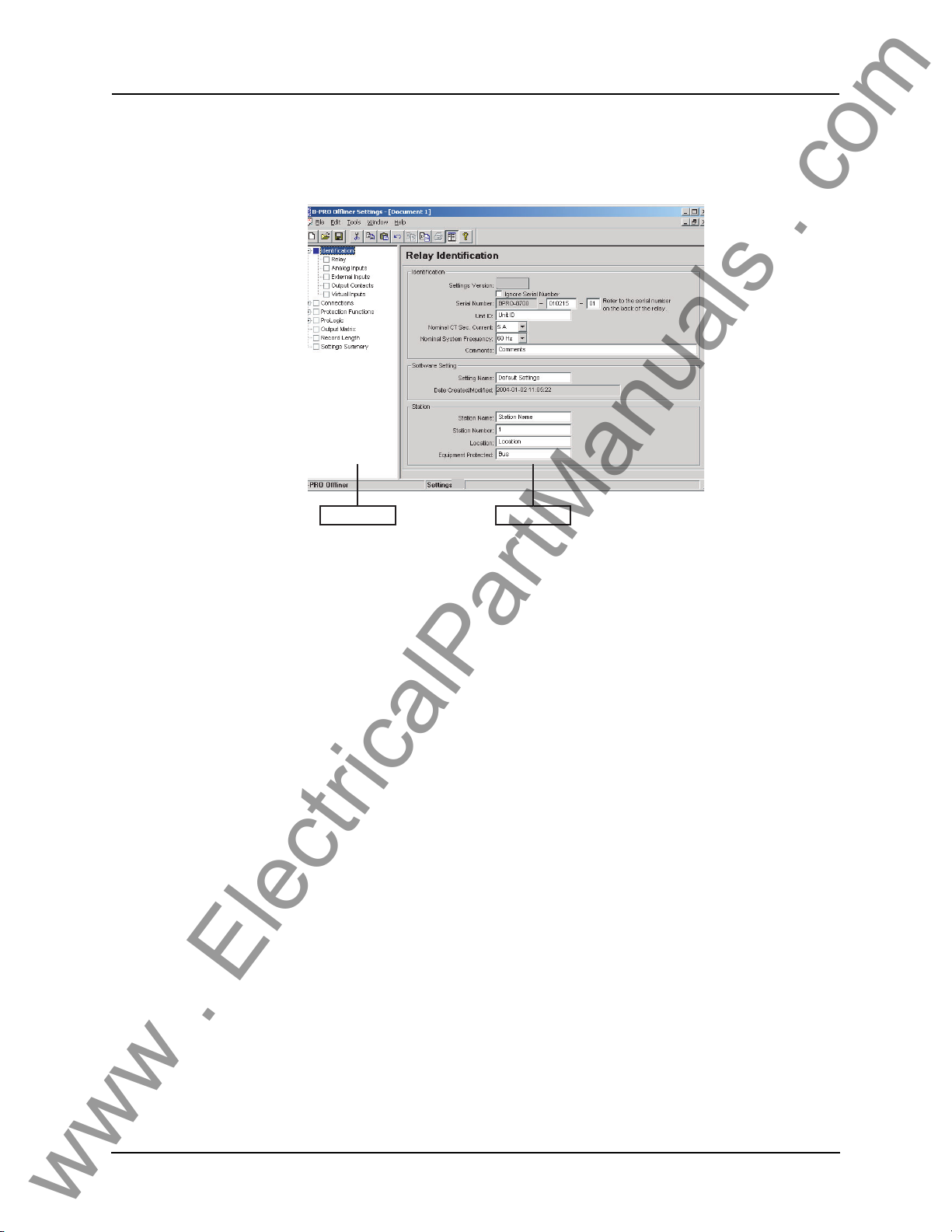
5 Offliner Settings Software
www . ElectricalPartManuals . com
4
v4
Setting Tree Setting Area
Figure 5.1: Opening Screen
Introduction
PC System
Requi
rements
Use the Offliner Settings software to create relay settings on a PC. Offliner provides an easy way to view and manipulat
ware versions and has the capability to convert older setting
newer ones.
Hardware
The minimum hardware requirements are:
• Pentium processor
• 64 MB of available RAM
• 100 MB of available hard-disk space recommended
• VGA monitor
• CD-ROM drive
• Serial communication port
Operating System
The following software must be installed and functional prior to installing
Offliner and RecordBase View software:
• Microsoft Windows 95, 98, ME, NT 4.0, 2000 or XP
e settings. Offliner supports all firm-
versions into
D01908R02.12 B-PRO User Manual 8700 5-1
Page 70
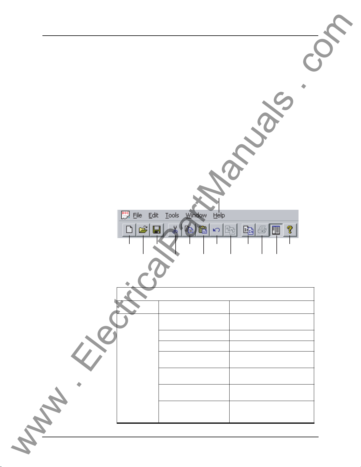
5 Offliner Settings Software
www . ElectricalPartManuals . com
Installing PC Software
Insert the CD-ROM in your drive. The CD-ROM should open automatically.
If the CD-ROM does not open automatically, go to Windows Explorer and find
the CD-ROM (usually on D drive). Open the B-PRO.exe file to launch the CDROM.
To install the software on your computer, click the de
sired item on the screen.
The installation program launches automatically. Installation may take a few
minutes to start.
To view the B-PRO User Manual you must have Adobe Acrobat on your computer. If you need a copy, download a copy by clicking on Download Adobe
Acroba
t.
Offliner Features
Menu and Toolbar The Offliner software includes the following menu and system tool bar. Figure
Figure 5.2: "Top Tool Bar" describes the details.
Help - User Manual
About B-PRO Offliner
New Save Copy
Open Cut Paste
Figure 5.2: Top Tool Bar
Undo
Copy
Inputs
Copy
Graph
to Clipboard
Print
About
Show or Hide
Left-Hand Side
Tree
Windows Menu
Windows Menu
Document Menu
(Icon)
5-2 B-PRO User Manual 8700 D01908R02.12
Sub Menu Comment
Restore Restores active window to previous
siz
e
Move Allows user to move active window
Size Allows user to resize active w
Minimize Makes the active window as small as
ssible
po
Maximize Makes the active window as large as
Close Closes the active Offliner setting doc-
Next Switches to the next open Offliner
ssible
po
ument
setting file, if mor
being edited
e than setting file is
indow
Page 71
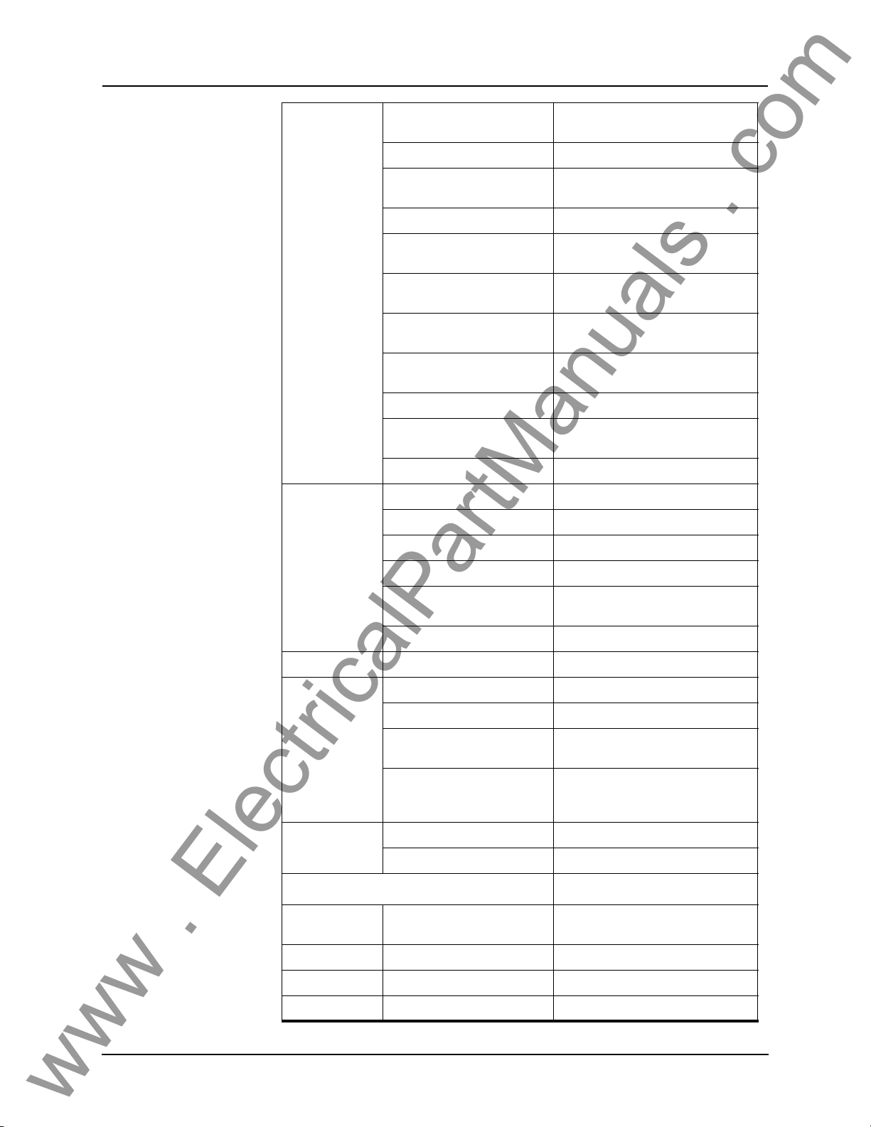
5 Offliner Settings Software
www . ElectricalPartManuals . com
File Menu New Opens up a default setting file of the
Open Open an existing setting file
Close Closes the active Offliner setting doc-
Save Saves the active setting file
Save As Saves the active setting file with a
Convert to Newer Convert an older setting version to a
Print Prints graphs or setting summary
Print Preview Provides a print preview of the setting
Print Setup Changes printers or print options
1-6 The six most recently accessed set-
Exit Quits the program
Edit Menu Undo Undo last action
Cut Cut the selection
most recent setting version
ument
w name or location
ne
wer version.
ne
pending on active screen
de
summary
ting files
Copy Copy the selection
Paste Insert clipboard contents
Copy Graph Copy the graph for the active screen
Copy Inputs Brings up the Copy Inputs dialog box
Tools Options Displays the Options Dialog Box
Window Cascade Cascades all open windows
Tile Tiles all open windows
Hide/Show Tree If this option is checked then the LHS
1-9, More Windows Allows access to all open Offliner set-
Help User Manual Displays the user manual
About Offliner Displays the Offliner version
Too lbar
New Create a new document. Create a new document of the most
Open Open an existing document. Open an existing document
clipboard
to the
ree view will be hidden
T
ting files. The active document will
ve a check beside it
ha
ecent setting version
r
Save Save the active document. Save the active document
Cut Cut the selection. Cut selection
D01908R02.12 B-PRO User Manual 8700 5-3
Page 72
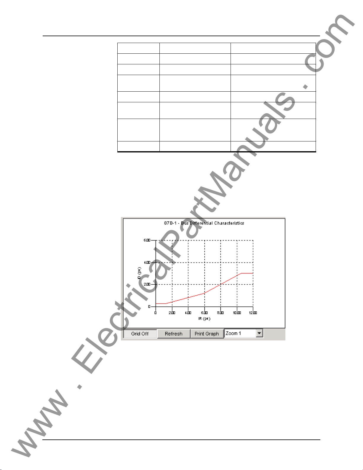
5 Offliner Settings Software
www . ElectricalPartManuals . com
Copy Copy the selection. Copy the selection
Paste Insert clipboard contents. Insert clipboard contents
Undo Copy graph to clipboard. Undo last action
Graphing Protection Function Characteristics
Copy Graph Copy the graph for the active sceen
Copy Inputs Copy inputs. Brings up the Copy Inputs dialog box
Show/Hide LHS
ee
Tr
Print Print active document. Prints Graphs or the setting sum-
About Display program information. Displays the Offliner version
clipboard
to the
If this option is checked then the LHS
Tree view will be hidden
mary, depending on which seen is
ted
selec
For the devices that have characteristics such as the 51 and 87, graphs have
been provided to aid in selecting settings. See Figure Figure 5.3: "87 Differential Slope Characteristic" and Figure Figure 5.4: "51 Inverse Time Overcurrent
Characteristic" for examples of these graphs. The
below. Note that the protection function must be enabled in order
graph features are described
to have it’s
characteristic displayed.
Figure 5.3: 87 Differential Slope Characteristic
5-4 B-PRO User Manual 8700 D01908R02.12
Page 73
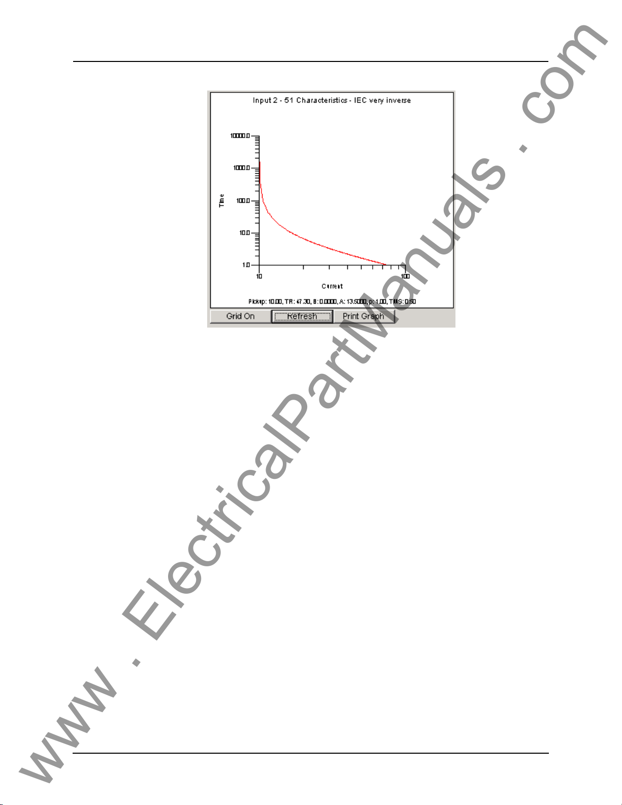
Figure 5.4: 51 Inverse Time Overcurrent Characteristic
www . ElectricalPartManuals . com
5 Offliner Settings Software
Grid On/Grid Off
The graph can be viewed with the grid on or off by clicking the Grid On or Grid
Off button. A right-click on the trace of the curve gives you the x and y coordinates.
Refresh
This button will manually refresh the graph if it has been zoomed.
Print Graph
To print a particular graph, click the Print Graph button.
Zoom on Graphs
Graphs can be zoomed to bring portions of the traces into clearer display. Leftclick on any graph and drag to form a small box around the graph area. When
you release the mouse, the trace assumes a new zoom position determined by
the area of the zoom coordinates.
To undo the zoom on the graph, cl
Displaying Co-ordinates
At any time you may right-click on the graph to display the co-ordinates of the
point you selected.
ick the Refresh button.
D01908R02.12 B-PRO User Manual 8700 5-5
Page 74
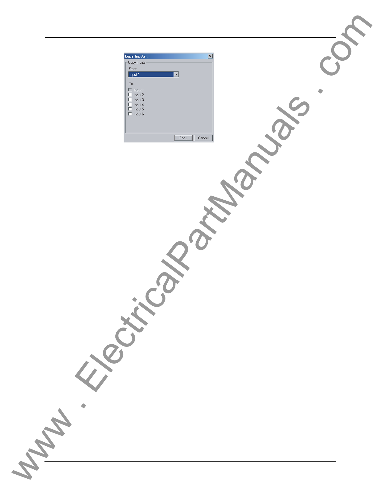
5 Offliner Settings Software
www . ElectricalPartManuals . com
Copying Input Protection
Figure 5.5: Copy Input Protection Functions
This feature allows the backup feeder protection that is provided for each input
to be copied from one input to another. All the settings are duplicated exactly,
including the output matrix. This is useful when you want to set each CT connection with the same protection characteristics.
This feature will copy all settings including the output matrix.
5-6 B-PRO User Manual 8700 D01908R02.12
Page 75
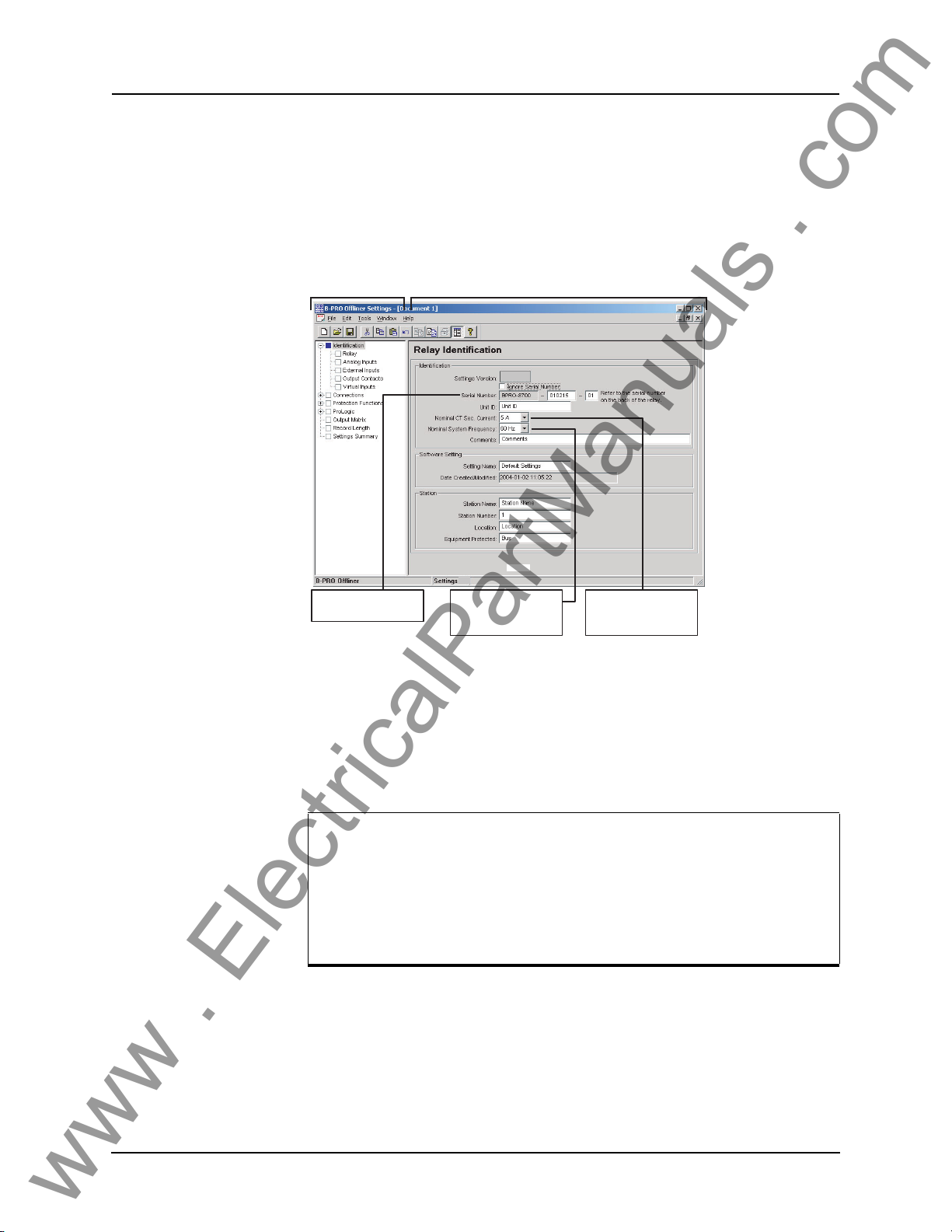
Main Branches from the Tree View
www . ElectricalPartManuals . com
This section will describe the tree view, which provides access to the various
setting screens. This section will not describe individual settings, but will provide a general description of where to find the individual settings. For a detailed description of the individual
5 Offliner Settings Software
settings, see Chapter 4.
LHS Menu Tree
Unique relay serial
number
Figure 5.6: Relay Identification
RHS - Information relating to specific menu Item,
accessed by LHS menu or top tabs.
4
v4
Nominal System
Frequency - set to
either 50 Hz or 60 Hz
Nominal CT Sec.
Current - set to either
1 A or 5 A
In the LHS Menu Tree there are a series of menu headings that may have sub
menus associated with them. Figure Figure 5.6: "Relay Identification" shows
the LHS tree view. Clicking on an item in the left hand
side tree view will dis-
play its corresponding menu in the RHS view. Similarly, you can use the arrow
eys to scroll through the menu tree.
k
The serial number of the relay must match the one in the setting file,
he setting will be rejected by the relay. This feature ensures that
or t
the correct setting file is applied to the right relay.
You can choose to ignore the serial number enforcement in the identification screen. The relay only checks for p
roper relay type and set-
ting version if the ignore serial number has been chosen.
Identification
Sub Menus
Relay, Analog Inputs, External Inputs, Output Contacts, Virtual Inputs.
These screens are where relay/station information can be entered, names
for
the relay I/O and model specific options such as nominal CT current and system frequency can be entered.
D01908R02.12 B-PRO User Manual 8700 5-7
Page 76

5 Offliner Settings Software
www . ElectricalPartManuals . com
Connections Sub Menus
System Parameters and Winding/CT
These menus contain the settings that are
that is connected to the relay. Settings such as Bus Base MVA, Nominal Voltage Level are made in the System Parame
contains settings such as differential zone, CT ratio settings, transformer settings and digital control.
used to define the primary system
ters screen. The Windings/CT screen
Protection
ctions
Fun
Sub Menus
Bus, Transformer, Inputs 1-6
These menus are used to make the individual settings for the various protection
de
vices provided by the relay. Each of the sub menus above can be broken further into sub menus for the different protec
lecting the Protection Functions item in the
Protection Summary screen in the RHS Tree view. This screen will display the
enabled/disabled status of all devices in the relay, and will also allow these devices to be enabled/disabled.
Bus Sub Menu
This sub menu contains the settings for the devices that are in the Bus Zone.
These functions are the 87B-1, 87B-2 and the voltage devices, 27, 59, 60, and
81.
Transformer Sub Menu
This sub menu contains only one item, the 87T settings. This is the only device
that is provided for the transformer protection zone.
Inputs 1-6 Sub Menus
These menus are where the settings for the backup feeder protection are located. Inputs 1-6 are identical and include menus for 50LS, 50BF, 50/51/67, 50N/
51N/67 and 46-50/46-51/
67 settings.
tive zones available. Note that se-
LHS tree view will display the
ProLogic
Output Matrix This is where the relay’s protection devices, external inputs,
Record Length This screen contains the settings for set
5-8 B-PRO User Manual 8700 D01908R02.12
Sub Menus
ProLogic 1 - ProLogic 15
This where each ProLogic statement that is pro
fined. There are 15 ProLogic statements available in the rela
screens. Similar to the Protection Functions menu, selecting ProLogic in the
LHS tree view will bring up the ProLogic Summary screen, which displays the
enabled/disabled status of all ProLogic. You can also enable or disable any
ProLogic from this screen. This unique ProLogic name is also displayed on this
screen, in brackets next to the generic ProLogic name.
ProLogics can be configured to close output contact(s) or trigger recordings.
ting the length of fault and swing re-
cording.
vided by the relay can be de-
y, so there are 15
virtual inputs, and
Page 77

5 Offliner Settings Software
www . ElectricalPartManuals . com
Settings Summary This menu provides a read-only list of all the relay’s settings. The setting
names, values, units and ranges are displayed. For the Protection devices, you
can use the "display and print only enabled protection devices" option from the
Tools menu to shorten the summary such that if a device is not enabled, its settings will be hidden, except that the enabl
ed setting will be displayed. This is
convenient if you are not using all of the available devices.
Offliner Keyboard Shortcuts
The following table lists the keyboard shortcuts that Offliner provides.
Ctrl+N
Ctrl+O
Ctrl+S
Ctrl+Z
Ctrl+X
Ctrl+C
Ctrl+V
Ctrl+F4
Ctrl+F6
F6
F10, Alt
F1
Opens up a default setting file of the most recent setting version
Open an existing setting file
Saves the active setting file
Undo
Cut
Copy
Paste
Closes the active Offliner setting document
Switches to the next open Offliner setting file, if
edited
Toggles between the LHS Tree view and HRS screen
Enables menu keyboard short-cuts
Displays the user manual
more than one setting file is being
D01908R02.12 B-PRO User Manual 8700 5-9
Page 78
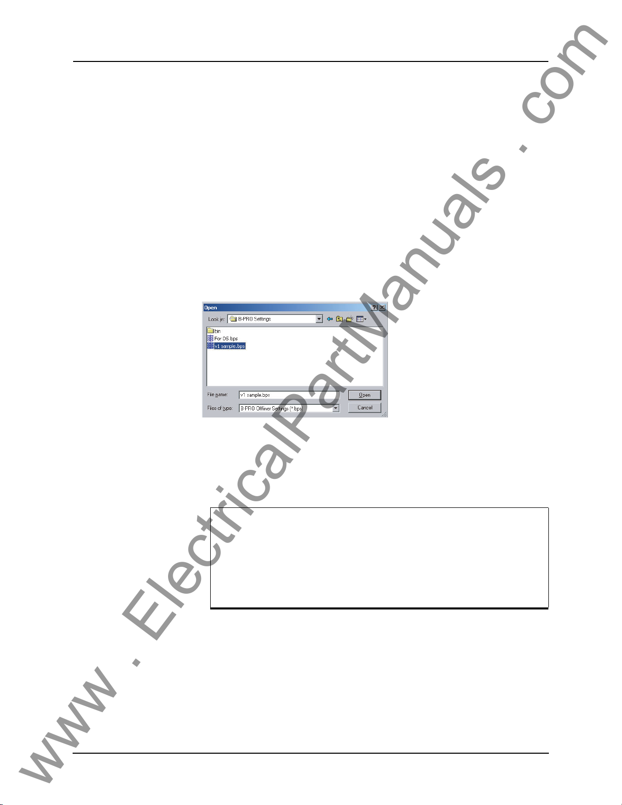
5 Offliner Settings Software
www . ElectricalPartManuals . com
Handling Backward Compatibility
Offliner Settings displays the version number in the second pane on the bottom
status bar. The settings version is a whole number (v1, v2, v3, v4, etc.).
The Off
files and convert older settings files to a newer version. Offliner Settings handles forward conversion only; it
file.
liner Settings is backward compatible. Open and edit older settings
converts an older setting file to a newer setting
Converting a
Settin
Sending a New Setting File to the Relay
gs File
1 Open the setting file you wish to convert.
2 In the Fi
(where x is the newer version). A dialog box pops up prompting Offliner for
a new file name. Use either the same file name or enter a new file name. The
conversion process inserts default values for any newly added devices in
the new setting file. When the conversion is complete, Offliner Settings displays the new file.
Figure 5.7: Converting Setting Files
1 Make sure the settings version and the
ting file match. The relay will reject the setti
ber or the settings version do not match.
le menu, select Convert to Newer... and then select the version x
serial number of the relay in the set-
ng file if either the serial num-
A “serial number discrepancy” message may appear. This is to ensure that you are aware of the exact relay in which settings are to
loaded. If this happens, check the relay serial number using the
be
terminal mode ID menu item. Type this serial number into the BPRO Serial No. box in the Identification tab display area of Offliner
Settings. Alternately you may check the Ignore Serial Number
check box to bypass serial number supervision.
2 Check the serial number and the setting
“ID” on page 3-10. The Device Serial Number and Required Settings Version on the Identification screen indicate
version of the relay.
5-10 B-PRO User Manual 8700 D01908R02.12
s version of the relay, for details see
the serial number and the settings
Page 79

5 Offliner Settings Software
www . ElectricalPartManuals . com
Creating a Setting File from an Older Version
1 Offliner Settings displays a default setting file on start up showing the set-
tings version in the bottom statu
shipped with a set of default sample files of older settings versions. These
sample files are “v1 sample.bps”, “v2 sample.bps”, “v3 sample.bps”, etc.
Each sample file contains default values of an older settings version. For a
new installation these sample files are placed in the default directory
C:\Program Files\NxtPhase\B-PRO Offliner Settings, or you can choose
the path during the Offliner software installation. If an older version of BPRO Offliner was previously installed on your PC, then the default directory may be C:\Program Files\AP
2 Open a sample file of the desired version. Use File/Save A
ple file to a new file name. Then edit the
save it and load it into the relay.
s bar. As an example B-PRO Offliner is
T\B-PRO Offliner Settings.
s to save the sam-
setting file and the serial number,
D01908R02.12 B-PRO User Manual 8700 5-11
Page 80
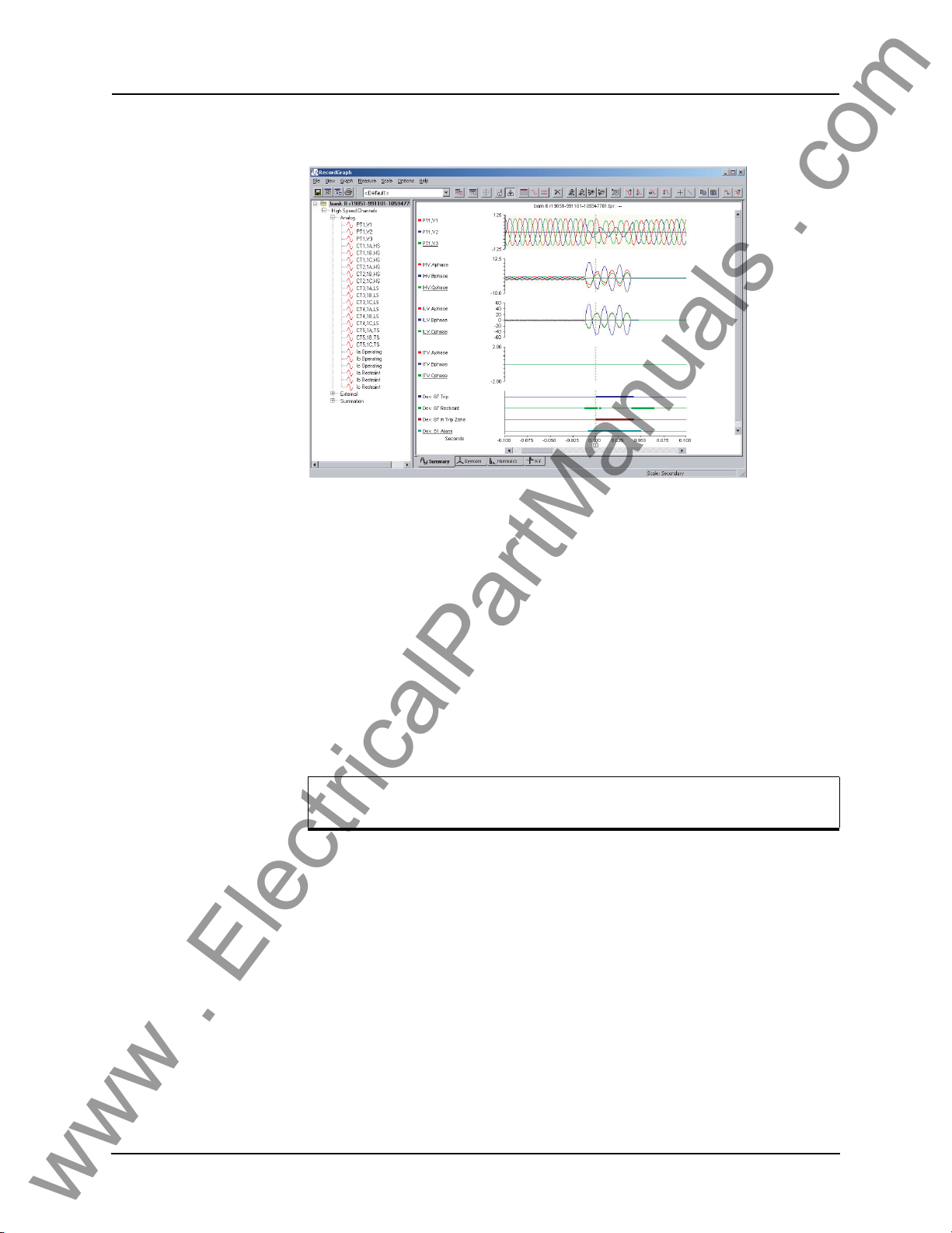
5 Offliner Settings Software
www . ElectricalPartManuals . com
RecordBase View Software
Figure 5.8: RecordBase View
Use RecordBase View to analyze the records from a relay.
1 Set the receive directory on your terminal program to point to
directory on your PC’s hard disk or network. For example with Windows
HyperTerminal, select Transfer>Receive File to set the receive directory.
2 Select one or more records on the relay using the Li
minal Mode’s Records me
3 Initiate transfer of the selected records by selecting R o
4 Start the RecordBase View program and use the File>Open menu command
open the downloaded record files located in the receive directory speci-
to
fied in step 1.
For further instructions refer to the RecordBase View Manual at the
back o
f the printed version of this manual.
nu.
st function in the Ter-
a convenient
n the keyboard.
5-12 B-PRO User Manual 8700 D01908R02.12
Page 81
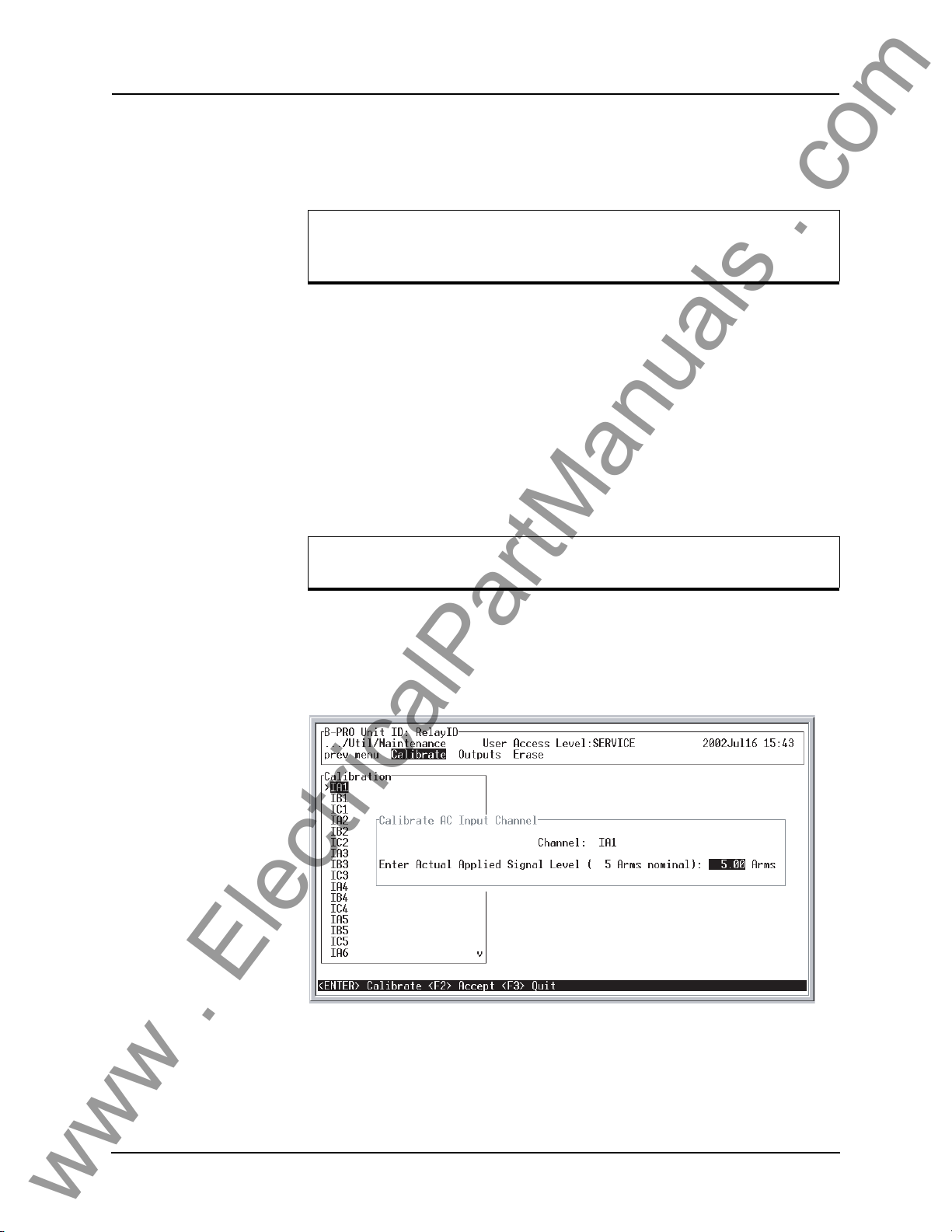
6 Testing the B-PRO Functions
www . ElectricalPartManuals . com
You can set Nominal CT Secondary Current to either 5 A or 1 A and
Nominal System Frequency to either 60 Hz or 50 Hz. This example
is set to 5 A/60 Hz.
Relay testing is required to determine if B-PRO performs correctly after the
settings are complete or to determine verification of relay settings needed. In
most cases a simple test using three voltage sources and three current sources
is adequate. Testing the bus differential element requires up to six sets of three
phase current sources when used in full capability. Use all the available metering functions during testing to verify
current signals.
issues such as polarities of voltage and
Calibration The relay is calibrated when it
made within the relay, you may need to do a re-calibration.
Before you begin a new calibration, establish the accuracy of the
equipment being used.
To perform a calibration, you must be logged into
at the Service access level. Proceed to the Utilities>Maintenance>Calibrate.
The Calibrate menu leads you through every analog input and prompts you to
apply the appropriate quantity.
leaves the factory; but if component changes are
the relay in Terminal Mode
Figure 6.1: Enter actual applied signal level
D01908R02.12 B-PRO User Manual 8700 6-1
Page 82
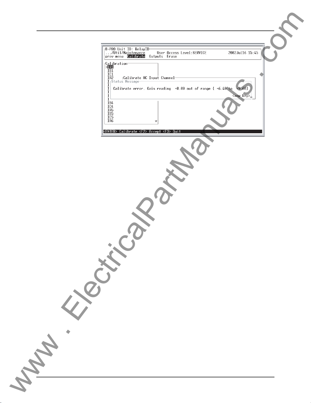
6 Testing the B-PRO Functions
www . ElectricalPartManuals . com
Figure 6.2: Calibration error - out of range
For example when you select voltage VA for calibration, a prompt appears
which asks you which quantity the relay should try to calibrate. If a 66 volt
phase to neutral quantity is applied to the back V
be indicated as the desired calibration.
In a similar way, you are prompted to go
and provide the information about the injected calibration quantities. You must
have a test source to perform the function. Only the magnitude of the analog
input requires calibration, not the angle.
When an input analog channel is calibrated,
ify it by selecting the Me
of the ac voltage input is used as a reference quantity by B-PRO. Therefore, if
it is absent, there is not a locked, valid relationship among all of the analog
quantities.
tering menu and the Analog Quantity submenu. VA
through all 21 ac analog quantities
A terminals, 66.0 volts would
the quantity measured you can ver-
Testing the External
Inp
uts
Testing the Output
Relay
Contacts
6-2 B-PRO User Manual 8700 D01908R02.12
To test the external inputs, connect the relay to a laptop in Terminal Mode, Service level>Metering>I/O.
put Contacts. Placing a voltage of 125 Vdc nominal, (150 V maximum), to
h of the external inputs in turn causes the input to change from Low to High
eac
status. These inputs are polarity sensitive and this screen has a 0.5 seconds update rate. The inputs should reset when th
volts. Testing requires application of a correct voltage polarity.
Test the output relays to verify their integrity using the Utilities>Maintenance>Outputs. The output contacts are clos
gles the output contacts from open
the output contact status using an ohmmeter. When you exit this sub-menu, all
contact status reverts to the open position
This screen displays the status of the Inputs and Out-
e dc voltage drops below about 80
ed by pressing the Enter key. Tog-
to closed by pressing the Enter key. Verify
Page 83
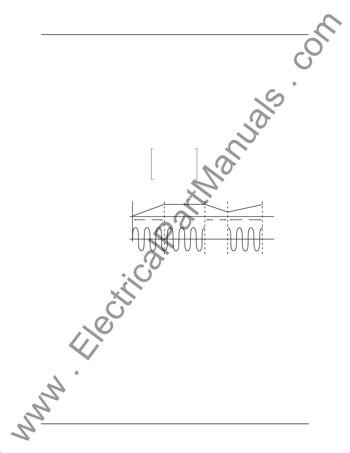
6 Testing the B-PRO Functions
www . ElectricalPartManuals . com
Testing the Inverse Time Overcurrent Function
Test function 51 by injecting current into the relay. The setting pickup of function 51 is done on a secondary current basis.
The equation for the IEEE overheating curves is displayed in the B-PRO Of-
Settings program and can be used to determine how long it takes to op-
fliner
erate the overcurrent function for a given
function is equation-driven and uses fixed constants to generate the operation
curves. See “50/51/67 Phase Overcurrent” on page 4-14 for details on the
equations and constants.
Test the 51 reset time by using the follow
test software to setup an appropriate test sequence and measure time t1, tx and
t2 to determine the relay’s performance with your setting parameters.
Equation 1
TR
TI() TMS
=
Torque
-----------------------------------
------------------
Pickup
2
I
1–
input current. The overcurrent curve
ing example and equations. Use your
Testing the Loss of
Poten
tial Function
t1 tx t2
Current
If then
txt
>
) t
I()
t
x
-----
t
2
Where t1 equals the time to operate for the applied current and tm equals the
value of solving Equation 1.
There are no user settings for device 60. If one or two of the AC voltages go
below 0.5 per unit or below 33.2 volt-seconds an ac Loss Of Potential alarm
will take place after a definite 10 second delay. This can be tested by dropping
all combinations of one and two voltages and waiting 10 seconds
t
⋅=
1
t
m
t1=
2
D01908R02.12 B-PRO User Manual 8700 6-3
Page 84
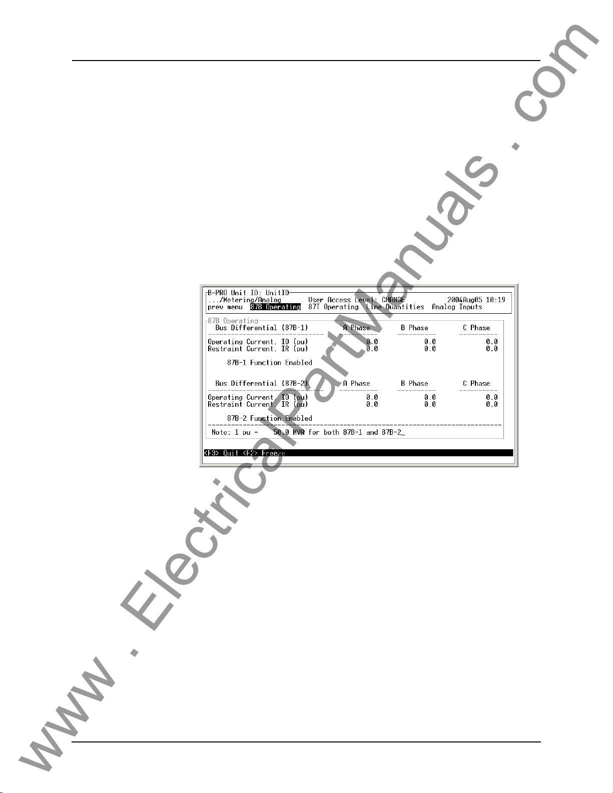
6 Testing the B-PRO Functions
www . ElectricalPartManuals . com
Some Additional Points to Consider
In all of the test cases, B-PRO can be set to trigger a transient fault record. Once
this is done, the fault record can be viewed, as can the point where the operation point crosses into the trip region. Als
rents can be performed to test all the functions of the relay. That is,
differential function between HV and LV can be performed. A test using all 15
currents could be performed. This presumes that fifteen synchronized currents
are available. A verification of operate IO and restraint IR quantities is possible
through the TERMINAL MODE by selecting the OPERATING QUANTITIES sub-menu. This screen indicates
within the relay.
Most protection functions also have picku
be programmed to produce outputs by enabling them in the OUTPUT MATRIX screens. These functions can be useful
layed functions where the user is trying to determine where the functi
starting to pickup.
o, any combination of injected cur-
the
the current pu quantity relationship
p level outputs available. These can
during testing, especially time de-
on is
Figure 6.3: Operating Quantities
6-4 B-PRO User Manual 8700 D01908R02.12
Page 85

7 Installation
www . ElectricalPartManuals . com
Physical Mounting
Standard 3U The relay is 3 rack units or 5.25 inches high and approximately 12.25 inches
deep. The standard relay is designed for a 19-inch rack. A complete mechanical drawing is shown, for
To install the relay yo
• 19 inch rack
• 4 - #10 screws
AC and DC Wiring
For details see “AC Schematic Drawing” in Appendix I and “DC Schematic
Drawing” in Appendix J.
Communication Wiring
EIA-232 The relay’s three serial ports (Ports 1, 2 and 3) are configured as EIA RS-232
Data Communications Equipment (DCE) devices with female DB9 connectors. This allows them
dard straight-through male
“Communication Port Details” on page 2-8.
details see “Mechanical Drawings” in Appendix G.
u need the following:
to be connected directly to a PC serial port with a stan-
-to-female serial cable. For pin-out details see
An adapter is available for connecting an ex
see “Modem Link - External” on page 2-3.
RJ-45 The relay may have an optional internal modem or an optional internal
0BaseT Ethernet port. Connection to either of these is via the relay’s Port 5
1
RJ-45 receptacle. Labeling above the port will indicate which option, if any,
has been installed.
IRIG-B Wiring The relay accepts both modulated and unmodulated IRIG-B standard time sig-
nals with or without the IEEE 1344 extensions.T
back of the relay is BNC type.
ternal modem to Port 2. For details,
he IRIG-B connector on the
D01908R02.12 B-PRO User Manual 8700 7-1
Page 86

www . ElectricalPartManuals . com
Page 87
Appendix A IED Specifications
www . ElectricalPartManuals . com
B-PRO Model 8700/BUS Specification
Item Quantity/Specs Note
General:
Nominal Frequency 50 or 60 Hz
Operate Time 8–20 ms for 87B function
12–24 ms for 87T function
Sampling Rate 96 samples/cycle for recording
Power Supply Nominal Range: 48–250 Vdc, 120 Vac
Memory Settings and records are stored in non-
Protection Functions:
IEEE Dev. 87B, 59, 27, 60, 81, 87T, 50LS,
50BF
, 50/51/67, 50N/51N/67, 46-50/46-
51/67
Recording:
Fault 96 s/c oscillography of all analog and
Dynamic Swing 1 s/c phasor measurements of line posi-
A/D Resolution 13 bits, 8192 counts full scale, peak–
8 samples/cycle for protection
Full Operating Range: 40–300 Vdc
atile memory.
vol
2 differential zones (bus and transformer, or Bus1 and Bus2) and overcurrent protection on each line.
external input channels.
Capacity: up to 15 x 2 second records
tive sequence V and I plus frequency
acity: up to 15 x 3 minute records
Cap
peak.
Including relay output operation.
Battery load is 50 watts or 50VA AC current.
Records are stored in a circular buffer.
15 ProLogic statements provide flexible
solutions.
Records up to the 25th harmonic.
Viewing software provides waveform,
symmetr
analysis.
ical components and harmonic
Events 250
Input and Output:
Analog Input Channels 18 currents and 3 voltages Rating: In = 5 A or 1 A Vn = 69 V
Continuous: 3x In, 2x Vn
One Second: 20x In without distortion
One Minute: 3x Vn, once/hour
Sampling Resolution
Burden (Analog Inputs) ac input voltage: < 0.15 VA @ 67 V
Analog Input Sampling
D01908R02.12 B-PRO User Manual 8700 Appendix A-1
12 bits plus sign, amplitude measure-
ment accuracy: ± 0.5% for 54 to 66 Hz
ac input current: < 0.50 VA @ 5 A
Sample rate: 96 samples/cycle for
recording, 8x/cycle for protection.
Page 88
Appendix A IED Specifications
www . ElectricalPartManuals . com
B-PRO Model 8700/BUS Specification
External Inputs 9 isolated inputs.
Burden Burden resistance: > 10 k ohms
Isolation Internal optical isolation
External Input Sampling Sample rate: 96 samples/cycle for
ing, 8x/cycle for protection
record
Output Relays (contacts) 14 programmable outputs plus
Interface & Communication:
Front Display 2 lines x 24 characters, fluorescent Exceptional visibility in all ambient light
Front Panel Indicators 6 LEDs Target, Relay Functional, IRIG-B Func-
Serial User Interface Front and rear RS-232 ports to 57.6 K
Internal Modem 33.6 Kbps, V.32 bis Optional internal modem
Network 10 Base T Ethernet port Optional Ethernet card
relay inoperative contact
baud
Optional 48–125 or 125–250 Vdc nomi-
nal, externally wetted.
Make: 30 A as per IEEE C37.90
Carry: 8 A
Break: 0.9 A at 125 Vdc resistive
0.35 A at 250 Vdc resistive
conditions.
tional, Service Required, Test Mode,
arm.
Al
Rear port can support an
external modem
SCADA Interface
Time Sync IRIG-B, BNC connector Modulated or unmodulated, auto-detect
Self Checking/Relay Inoperative 1 contact Closed when relay inoperative.
Terminal User Interface VT100 terminal emulation
Environmental:
Ambient Temperature Range -40°C to 85°C IEC 60068-2-1/IEC 60068-2-2
Humidity Up to 95% without condensation IEC 60068-2-30
Insulation Test (Hi-Pot) Power supply, analog inputs, external
Electrical Fast Transient ANSI/IEEE C37.90.1 - 1989
Oscillatory Transient ANSI/IEEE C37.90.1 - 1989
RFI Susceptibility ANSI/IEEE C37.90.2, IEC 255-22-3
Shock and Bump IEC 60255-21-2 Class 1
Sinusoidal Vibration
DNP3 (RS-232 or Ethernet) or Modbus
S-232)
(R
inputs, output contacts – 1.5 kV, 50/60
Hz, 1 minute.
10Hz to 150Hz, 0.15mm or 20m/s
10 sweep cycles
2
Rear port
Accessible via serial, modem or net-
work interface.
IEC 60255-5
IEC 60068-2-6
Physical:
Appendix A-2 B-PRO User Manual 8700 D01908R02.12
Page 89
Appendix A IED Specifications
www . ElectricalPartManuals . com
B-PRO Model 8700/BUS Specification
Weight 11.52 kg 25.40 lbs
Dimensions 13.3 cm 3U high, 5.25"
48.3 cm rack mount 19" rack mount
30.5 cm deep 12” deep
Mounting Horizontal
Time Synchronization and Accuracy:
External Time Source
Synchronization Accuracy
Overall B-PRO Accuracies:
Current ± 2.5% of inputs from 0.1 to 1.0 x nominal current (In)
Voltage ± 1.0% of inputs from 0.01 to 2.0 x nominal voltage (Vn)
Timers ± 3 ms of set value
Inverse Overcurrent Times ± 2.5% or ± 1 cycle of selected curve
Definite Overcurrent Times ± 2.5% or ± 1 cycle non-directional
The B-PRO relay is synchronized using
IRIG-B input (
lated) auto detect.
Sampling clocks synchronized with the
time sou
± 1.0% of inputs from 1.0 to 20.0 x nominal current (In)
modulated or unmodu-
rce (internal or external).
Free Running Accuracy: In the absence
of an external time source, the relay
maintains time with a maximum ±15
minutes drift per year over the full oper-
ating temperature range, and maxi-
mum ±90 seconds drift per year at a
const
ant temperature of 25°C. The
relay can detect loss or re-establish-
ment of external time source and auto-
matically switch between internal and
external time.
± 2.5% or ± 1.5 cycle directional
Frequency Timers ± 3 ms of set value plus 1.25 cycles to 1.75 cycles o
Burden AC Voltage Inputs, < 0.15 VA @ 69 volts
AC Current Inputs, < 0.50 VA @ 5 amps
D01908R02.12 B-PRO User Manual 8700 Appendix A-3
f inherent delay
Page 90

www . ElectricalPartManuals . com
Page 91
Appendix B IED Settings and Ranges
www . ElectricalPartManuals . com
When a setting has been completed in the B-PRO Offliner Settings software, it
can be printed along with the ranges available for these settings. This is a view
only option, that is, if the user wants to change settings they must go back into
the settings portion dealing with that setting to make changes. The summary is
however, a quick way of having a look at all the settings in a very compact
form.
The top part of the settings summary identifies t
done, the relay identification, the station that the relay is applied and the location.
The setting summary provides a list of all the current and
quantity names used for line protection and used for recording. External Inputs
and Output contact names are also identified on this summary.
Settings Summary - B-PRO 8700
Name Symbol/Value Unit Range
Relay Identification
Settings Version 4
Ignore Serial Number No
Serial Number BPRO-8700-010215-01
Nominal CT Secondary Current 5 A
Nominal System Frequency 60 Hz
Relay ID RelayID
Comments Comments
Date Created-Modified 2002-06-21 14:10:22
Station Name Station Name
Station Number 1
Location Location
Equipment Protected Bus
Analog Input Names
Voltage Input Name BUS PT 1
VA Voltage A
VB Voltage B
VC Voltage C
Input 1 Input1
IA1 Input1 Current A
IB1 Input1 Current B
IC1 Input1 Current C
Input 2 Input2
IA2 Input2 Current A
he date that the settings were
voltage analog input
D01908R02.12 B-PRO User Manual 8700 Appendix B-1
Page 92
Appendix B IED Settings and Ranges
www . ElectricalPartManuals . com
Settings Summary - B-PRO 8700
IB2 Input2 Current B
IC2 Input2 Current C
Input 3 Input3
IA3 Input3 Current A
IB3 Input3 Current B
IC3 Input3 Current C
Input 4 Input4
IA4 Input4 Current A
IB4 Input4 Current B
IC4 Input4 Current C
Input 5 Input5
IA5 Input5 Current A
IB5 Input5 Current B
IC5 Input5 Current C
Input 6 Input6
IA6 Input6 Current A
IB6 Input6 Current B
IC6 Input6 Current C
External Input Names
1 EI Spare 1
2 EI Spare 2
3 EI Spare 3
4 EI Spare 4
5 EI Spare 5
6 EI Spare 6
7 EI Spare 7
8 EI Spare 8
9 EI Spare 9
Output Contact Names
Output 1 Out Spare 1
Output 2 Out Spare 2
Output 3 Out Spare 3
Output 4 Out Spare 4
Output 5 Out Spare 5
Output 6 Out Spare 6
Output 7 Out Spare 7
Output 8 Out Spare 8
Output 9 Out Spare 9
Output 10 Out Spare 10
Appendix B-2 B-PRO User Manual 8700 D01908R02.12
Page 93
Appendix B IED Settings and Ranges
www . ElectricalPartManuals . com
Settings Summary - B-PRO 8700
Output 11 Out Spare 11
Output 12 Out Spare 12
Output 13 Out Spare 13
Output 14 Out Spare 14
System Parameters
Bus 1 MVA 100.0 MVA Primary 1.0 to 1000.0
Bus 2 MVA 100.0 MVA Primary 1.0 to 1000.0
Bus Voltage 230.0 kV Primary 1.0 to 1000.0
PT Turns Ratio 10000.0 :1 1.0 to 10000.0
Phase Rotation ABC
Directional Control Alpha 0.0 degrees -179.9 to 180.0
Directional Control Beta 180.0 degrees 0.1 to 360.0
Winding/CT Connections
Differential Zone Bus only
Bus side:
Voltage 230.0 kV Primary 1.0 to 1000.0
Connection Y
Phase 0° degree ref (fixed)
Non-Bus side:
Voltage 115. 0 kV Primary 1.0 to 1000.0
Connection Y
Phase 0°
Transformer 3 Phase MVA 60.0 MVA Primary 1.0 to 2000.0
CT Connections
Input 1 [Input1]
Connect to Bus
CT Connection Y (fixed)
CT Phase 0° (fixed)
CT Turns Ratio (to 1) 100.0 :1 -
Digital Control Enabled
Digital Control Selection Not Used
Exclude When High
Input 2 [Input2]
Connect to Bus
CT Connection Y (fixed)
CT Phase 0° (fixed)
CT Turns Ratio (to 1) 100.0 :1 -
Digital Control Enabled
Digital Control Selection Not Used
D01908R02.12 B-PRO User Manual 8700 Appendix B-3
Page 94
Appendix B IED Settings and Ranges
www . ElectricalPartManuals . com
Settings Summary - B-PRO 8700
Exclude When High
Input 3 [Input3]
Connect to Bus
CT Connection Y (fixed)
CT Phase 0° (fixed)
CT Turns Ratio (to 1) 100.0 :1 -
Digital Control Enabled
Digital Control Selection Not Used
Exclude When High
Input 4 [Input4]
Connect to Bus
CT Connection Y (fixed)
CT Phase 0° (fixed)
CT Turns Ratio (to 1) 100.0 :1 -
Digital Control Enabled
Digital Control Selection Not Used
Exclude When High
Input 5 [Input5]
Connect to Bus
CT Connection Y (fixed)
CT Phase 0° (fixed)
CT Turns Ratio (to 1) 100.0 :1 -
Digital Control Enabled
Digital Control Selection Not Used
Exclude When High
Input 6 [Input6]
Connect to Bus
CT Connection Y
CT Phase 0°
CT Turns Ratio (to 1) 100.0 :1 -
Digital Control Enabled
Digital Control Selection Not Used
Exclude When High
Protection Summary
87B Enabled
87T Disabled
60 Enabled
27-1 Enabled
27-2 Enabled
Appendix B-4 B-PRO User Manual 8700 D01908R02.12
Page 95
Settings Summary - B-PRO 8700
www . ElectricalPartManuals . com
59-1 Enabled
59-2 Enabled
81 O/F-1 Enabled
81 O/F-2 Enabled
81 U/F-1 Enabled
81 U/F-2 Enabled
Input 1 [Input1] Protection
50BF Enabled
50LS-1 Enabled
50LS-2 Enabled
50 Enabled
51 Enabled
50N Enabled
51N Enabled
46-50 Enabled
46-51 Enabled
Input 2 [Input2] Protection
50BF Disabled
50LS-1 Disabled
50LS-2 Disabled
50 Disabled
51 Disabled
50N Disabled
51N Disabled
46-50 Disabled
46-51 Disabled
Input 3 [Input3] Protection
50BF Disabled
50LS-1 Disabled
50LS-2 Disabled
50 Disabled
51 Disabled
50N Disabled
51N Disabled
46-50 Disabled
46-51 Disabled
Input 4 [Input4] Protection
50BF Disabled
50LS-1 Disabled
Appendix B IED Settings and Ranges
D01908R02.12 B-PRO User Manual 8700 Appendix B-5
Page 96
Appendix B IED Settings and Ranges
www . ElectricalPartManuals . com
Settings Summary - B-PRO 8700
50LS-2 Disabled
50 Disabled
51 Disabled
50N Disabled
51N Disabled
46-50 Disabled
46-51 Disabled
Input 5 [Input5] Protection
50BF Disabled
50LS-1 Disabled
50LS-2 Disabled
50 Disabled
51 Disabled
50N Disabled
51N Disabled
46-50 Disabled
46-51 Disabled
Input 6 [Input6] Protection
50BF Disabled
50LS-1 Disabled
50LS-2 Disabled
50 Disabled
51 Disabled
50N Disabled
51N Disabled
46-50 Disabled
46-51 Disabled
87B-1 - Bus Differenti al
87B-1 Enabled
IOmin 0.25 p. u. 0.20 to 0.40
IRs 2.00 p. u. 1.25 to 50.00
S1 20.00 % 12.50 to 40.00
S2 40.00 % 30.00 to 200.00
High Curr. Setting 10.00 p. u. 0.75 to 100.00
CT Saturation Detection Disabled
CT Saturation Max Block 1.00 - 0.10 to 99.99
87B-2 - Bus Differenti al
87B-2 Enabled
IOmin 0.25 p. u. 0.20 to 0.40
Appendix B-6 B-PRO User Manual 8700 D01908R02.12
Page 97
Appendix B IED Settings and Ranges
www . ElectricalPartManuals . com
Settings Summary - B-PRO 8700
IRs 2.00 p. u. 1.25 to 50.00
S1 20.00 % 12.50 to 40.00
S2 40.00 % 30.00 to 200.00
High Curr. Setting 10.00 p. u. 0.75 to 100.00
CT Saturation Detection Disabled
CT Saturation Max Block 1.00 - 0.10 to 99.99
87T - Transformer Differential
87T Disabled
IOmin 0.25 p. u. 0.10 to 0.40
IRs 2.00 p. u. 1.25 to 50.00
S1 20.00 % 12.50 to 40.00
S2 40.00 % 30.00 to 200.00
High Curr. Setting 10.00 p. u. 0.75 to 100.00
I_2nd / I_fund Ratio 0.20 - 0.05 to 1.00
I 5th Harmonic Restraint Disabled
I_5th / I_fund Ratio 0.20 - 0.05 to 1.00
27 - Undervoltage
27-1 Enabled
Gate Switch OR
Pickup 20.0 volts 1.0 to 120.0
Pickup Delay 1.00 seconds 0.00 to 99.99
27-2 Enabled
Gate Switch OR
Pickup 20.0 volts 1.0 to 120.0
Pickup Delay 1.00 seconds 0.00 to 99.99
59 - Overvoltage
59-1 Enabled
Gate Switch OR
Pickup 70.0 volts 60.0 to 140.0
Pick-up Delay 1.00 seconds 0.00 to 99.99
59-2 Enabled
Gate Switch OR
Pickup 70.0 volts 60.0 to 140.0
Pickup Delay 1.00 seconds 0.00 to 99.99
60 - Loss of Potential Alarm
60 Enabled
81 - Over-Frequency
81 O/F-1 Enabled
Pickup 61.00 Hz 60.00 to 70.00
D01908R02.12 B-PRO User Manual 8700 Appendix B-7
Page 98
Appendix B IED Settings and Ranges
www . ElectricalPartManuals . com
Settings Summary - B-PRO 8700
Pickup Delay 2.00 seconds 0.05 to 99.99
81 O/F-2 Enabled
Pickup 62.00 Hz 60.00 to 70.00
Pickup Delay 2.00 seconds 0.05 to 99.99
81 - Under-Frequency
81 U/F-1 Enabled
Pickup 59.50 Hz 50.00 to 60.00
Pickup Delay 2.00 seconds 0.05 to 99.99
81 U/F-2 Enabled
Pickup 59.00 Hz 50.00 to 60.00
Pickup Delay 2.00 seconds 0.05 to 99.99
Input 1 [Input1], 50BF - Breaker Failure
50BF Enabled
BF Initiated By 87B-1 Disabled
BF Initiated By 87B-2 Disabled
BF Initiated By 87T Disabled
BF Initiated By ProLogic Disabled
BF Initiated By Ext. Input Disabled
Pickup Delay 1 0.50 seconds 0.01 to 99.99
Pickup Delay 2 1.50 seconds 0.01 to 99.99
Input 1 [Input1], 50LS - Low Set Overcurrent
50LS-1 Enabled
Gate Switch OR
Pickup 1.0 amperes 0.1 to 50.0
Pickup Delay 0.00 seconds 0.00 to 99.99
50LS-2 Enabled
Gate Switch OR
Pickup 1.0 amperes 0.1 to 50.0
Pickup Delay 0.00 seconds 0.00 to 99.99
Input 1 [Input1], 50/51/67 - Phase Overcurrent
50 Enabled
Directional Control forward
Pickup 10.0 amperes 0.5 to 50.0
Pickup Delay 1.00 amperes 0.00 to 99.99
Breaker Failure Initiated Disabled
51 Enabled
Directional Control forward
Pickup 10.0 amperes 0.5 to 50.0
Appendix B-8 B-PRO User Manual 8700 D01908R02.12
Page 99
Appendix B IED Settings and Ranges
www . ElectricalPartManuals . com
Settings Summary - B-PRO 8700
Breaker Failure Initiated Disabled
Curve Type IEC very inverse
A 13.5 - -
B 0.0 - -
p 1.0 - -
TR 47.30 - -
TMS 0.50 - 0.01 to 10.00
Input 1 [Input1], 50N/51N/67 - Neutral
Overcurrent
50N Enabled
Directional Control forward
Pickup 10.0 amperes 0.5 to 50.0
Pickup Delay 1.00 amperes 0.00 to 99.99
Breaker Failure Initiated Disabled
51N Enabled
Directional Control forward
Pickup 10.0 amperes 0.5 to 50.0
Breaker Failure Initiated Disabled
Curve Type IEC very inverse
A 13.5 - -
B 0.0 - -
p 1.0 - -
TR 47.30 - -
TMS 0.50 - 0.01 to 10.00
Input 1 [Input1], 46-50/46-51/67 - Negative
Sequence Overcurrent
46-50 Enabled
Directional Control forward
Pickup 10.0 amperes 0.5 to 50.0
Pickup Delay 1.00 amperes 0.00 to 99.99
Breaker Failure Initiated Disabled
46-51 Enabled
Directional Control forward
Pickup 10.0 amperes 0.5 to 50.0
Breaker Failure Initiated Disabled
Curve Type IEC very inverse
A 13.5 - -
B 0.0 - -
p 1.0 - -
TR 47.30 - -
D01908R02.12 B-PRO User Manual 8700 Appendix B-9
Page 100
Appendix B IED Settings and Ranges
www . ElectricalPartManuals . com
Settings Summary - B-PRO 8700
TMS 0.50 - 0.01 to 10.00
Input 2 [Input2], 50BF - Breaker Failure
50BF Disabled
BF Initiated By 87B-1 Disabled
BF Initiated By 87B-2 Disabled
BF Initiated By 87T Disabled
BF Initiated By ProLogic Disabled
BF Initiated By Ext. Input Disabled
Pickup Delay 1 0.50 seconds 0.01 to 99.99
Pickup Delay 2 1.50 seconds 0.01 to 99.99
Input 2 [Input2], 50LS - Low Set Overcurrent
50LS-1 Disabled
Gate Switch OR
Pickup 1.0 amperes 0.1 to 50.0
Pickup Delay 0.00 seconds 0.00 to 99.99
50LS-2 Disabled
Gate Switch OR
Pickup 1.0 amperes 0.1 to 50.0
Pickup Delay 0.00 seconds 0.00 to 99.99
Input 2 [Input2], 50/51/67 - Phase Overcurrent
50 Disabled
Directional Control forward
Pickup 10.0 amperes 0.5 to 50.0
Pickup Delay 1.00 amperes 0.00 to 99.99
Breaker Failure Initiated Disabled
51 Disabled
Directional Control forward
Pickup 10.0 amperes 0.5 to 50.0
Breaker Failure Initiated Disabled
Curve Type IEC very inverse
A 13.5 - -
B 0.0 - -
p 1.0 - -
TR 47.30 - -
TMS 0.50 - 0.01 to 10.00
Input 2 [Input2], 50N/51N/67 - Neutral
Overcurrent
50N Disabled
Appendix B-10 B-PRO User Manual 8700 D01908R02.12
 Loading...