

Page 1

Users Manual
LCC International, Inc.
Page 2

SpectraWave 1900 Users Manual
LCC p/n 41-A00818-1
Copyright © 1998 LCC International, Inc. All Rights Reserved
7925 Jones Branch Drive, McLean, Virginia 22102
Phone: (703) 873-2000 FAX: (703) 873-2100
Customer Support: 1-800-522-9670
8:00 AM - 8:00 PM Eastern Standard Time (EST)
e-mail: [email protected]
If you have any questions regarding this manual, contact Hardware Customer Support at the phone numbers above, or
send an e-mail to: [email protected]. You also can contact us at our website at www.lcc.com.
Software License Agreement
The software described in this document has been provid ed under a separate Software License Agreement. The
software in this document may be used and copied only in accordance with such Software License Agreement.
Unauthorized use or copying of the software, this document or any related materials may result in civil liability
and/or criminal prosecution.
The information in this document is subject to change without notice and does not represent commitment on
the part of LCC International, Inc. The software License Agreement sets forth the only warranties made by
LCC International, Inc. with respect to the software. Such warranties are in lieu of, and LCC expressly disclaims, any and all other warranties, express or implied, statutory or otherwise.
LCC is a service mark of LCC International, Inc.
SpectraWave 1900 is a trademark of LCC International, Inc.
Page 3

Contents
1 Introduction
1.1 About This Manual............................................................................................ 1-1
1.2 What is in this Manual.......................................................................................1-2
1.3 Document Conventions...................................................................................... 1-2
1.4 Technical Support..............................................................................................1-3
2 SpectraWave 1900 Transmitter Basics
2.1 Basic Transmitter Configuration ....................................................................... 2-2
2.2 User Interface..................................................................................................... 2-3
2.2.1 Menu-Driven Screens Display.................................................................. 2-3
2.2.2 Numerical Screens (Power and Frequency).............................................. 2-6
2.2.3 Status Lights ............................................................................................. 2-6
2.2.4 Antenna Accessory Kit............................................................................. 2-6
2.2.5 Transmitter Power Supply ........................................................................ 2-7
2.3 SpectraWave 1900 Convenience Features......................................................... 2-8
2.4 Preparing SpectraWave 1900 for Operation...................................................... 2-9
2.4.1 Checking and Maintaining the Air Filter.................................................. 2-9
2.4.2 Setting Up the SpectraWave 1900..........................................................2-10
2.4.3 Setting Test Parameters .......................................................................... 2-11
2.5 Preparing SpectraWave 1900 for Shipping ..................................................... 2-12
3 Quick Start
3.1 Powering Up SpectraWave 1900....................................................................... 3-2
3.2 Status Menu Screen ........................................................................................... 3-3
3.3 Setup Menu Screen............................................................................................ 3-3
3.3.1 Protocol Screen.........................................................................................3-4
3.3.2 Frequency/Channel Screen ....................................................................... 3-5
3.3.3 Power Screen ............................................................................................3-6
3.3.4 Clock Setup Screen................................................................................... 3-7
3.3.5 LCD Contrast Setup Screen...................................................................... 3-8
3.3.6 Setup Menu-2 Screen................................................................................ 3-9
3.3.6.1 Cable Loss (Lc) Screen ............................................................. 3-10
3.3.6.2 Antenna Gain (Ga) Screen ........................................................3-11
3.4 Diagnostics Menu Screen ................................................................................3-12
3.4.1 Error Log View/Log Screen ................................................................... 3-13
3.4.2 Power Amp Status Screen....................................................................... 3-15
3.4.3 Voltage Status Screen............................................................................. 3-16
3.4.4 Synthesizer Status Screen....................................................................... 3-17
3
Page 4

Contents
3.4.5 Ambient Temperature Screen................................................................. 3-18
3.4.6 Diagnostics Menu-2 Screen....................................................................3-19
3.5 Setting Up an PCS 1900 Protocol.................................................................... 3-20
4 Functional Screens
4.1 Using Setup Functions.......................................................................................4-3
4.1.1 Selecting Protocol.....................................................................................4-3
4.1.2 Selecting Frequency and Channel Number .............................................. 4-5
4.1.3 Selecting Power ........................................................................................ 4-6
4.1.4 Setting the Clock and Date ....................................................................... 4-7
4.1.5 Setting the LCD Contrast.......................................................................... 4-8
4.1.6 Setting Cable Loss Value.......................................................................... 4-9
4.1.7 Setting Antenna Gain Value .................................................................. 4-11
4.2 Using the Diagnostic Functions....................................................................... 4-12
4.2.1 Displaying the Error Log View/Clear..................................................... 4-13
4.2.2 Viewing the Power Amp Status.............................................................. 4-15
4.2.3 Viewing Voltage Status .......................................................................... 4-16
4.2.4 Viewing Synthesizer Status .................................................................... 4-17
4.2.5 Viewing Ambient Temperature Status ................................................... 4-18
4.2.6 Downloading Firmware Files ................................................................. 4-18
4.2.7 Downloading Calibration Files and TX IDs...........................................4-21
4.2.8 Viewing Transmitter Information........................................................... 4-21
4.3 Using Status Menu Options............................................................................. 4-23
Appendix A Specifications
SpectraWave Models Available................................................. A-1
Performance Specifications........................................................ A-1
Physical Specifications............................................................... A-1
User Interface............................................................................. A-2
Key Features............................................................................... A-2
Accessories................................................................................. A-2
Appendix B Error Codes
4
Page 5

Introduction
SpectraWave 1900 is a continuous wave transmitter that simulates cell sites
during candidate site evaluation and RF design validation. The SpectraWave
1900 transmitter continuously monitors key performance metrics and
frequency output to maintain tolerances of 0.5 Parts Per Million (PPM). This
design tool uses an advanced thermal design that ensures the same level of
output accuracy in virtually any climate within a temperature range of -4° to
+140° F (-20° to +60° C).
The SpectraW ave 1900 transmitter is designed to operate almost anywhere you
can locate an antenna. Its casing and structure are strong enough to withstand
harsh environments, including shock and vibration. With its small size and
weight, you can move SpectraWave 1900 easily to a variety of locations for
testing.
After selecting a potential site, use SpectraWave 1900 to transmit a signal over
a single frequency . Use SpectraWave 1900 in conjunction with RSAT-2000 (or
the EXP-2001 to measure the signal and collect data for later analysis) for safe,
easy, and productive data measurement.
1
Figure 1 - 0:
1.1 About This Manual
This SpectraWave 1900 User’s Manual contains information intended for
engineers and technicians of wireless systems who have a basic knowledge of
wireless telephony. This manual includes only minimal information on
industry standards related to the operation of SpectraWave 1900.
Page 6

Introduction
1.2 What is in this Manual
This manual includes the following sections:
• Quick Start, a step-by-step guide to basic SpectraWave 1900
operation.
• Functional Screens details all of the various displays that
SpectraWave 1900 generates, and the data that they present, and
information on configuring that data.
• Appendixes provide additional technical information and discuss
optional software.
The typical SpectraWave 1900 user operates a unit that has already been
installed in a test vehicle and will not need to install the system.
1.3 Document Conventions
This manual uses specific type fonts to indicate certain meanings. Computer
file names and directories appear in Courier New Bold. T erms that appear
in a graphical user interface (GUI) are in Times New Roman Bold. Keyboard
entries appear in Courier New (plain).
Page numbering includes the chapter number and the page within the chapter.
For example, 2-2 is Chapter Two, Page Two.
Figures and tables are numbered according to the chapter and the sequence in
which they appear in the chapter. For example, Figure 2-1 is the first figure in
Chapter Two.
Note: Text in this format pertains to the topic being discussed in regular text
and is set aside to emphasize a particular point.
CAUTION: Text found in this format is vitally important to proper operation
of SpectraWave 1900. Please pay careful attention to these
items.
Introduction - 2
Page 7

1.4 Technical Support
WARNING!: Text found in this format alert users to hazardous conditions that
may result in bodily harm. Pay strict attention to these.
1.4 Technical Support
Direct questions regarding set up and use of SpectraWave 1900 to LCC
Customer Support at (800) 522-9670. You also can contact LCC via e-mail at
[email protected], or at our web site, www.lcc.com.
1 - 3
Page 8

1.4 Technical Support
1 - 4
Page 9

SpectraWave 1900 Basics
Figure 2 - 0:
SpectraWave 1900 is a continuous wave transmitter that simulates cell
sites during candidate site evaluation and RF design validation. Use
SpectraWave 1900 to measure potential performance of an antenna at
the sites you are considering as antenna locations.
The SpectraWave 1900 transmitter transmits a signal over a single
frequency at a potential antenna site. SpectraWave 1900 also can be
combined with RSAT-2000 (or with the EXP-2001/Benchmarker) to
measure the signal and collect data for later analysis for safe, easy, and
productive data measurement. Use the SpectraWave 1900 transmitter
to evaluate and compare the signal strength you can expect from
locating the antenna at different sites within a cell. Use
SpectraW ave 1900 to evaluate the level of interference from a potential
cell site to adjacent sites.
The SpectraWave 1900 transmitter continuously monitors key
performance metrics and its frequency output to maintain a tolerance of
0.5 PPM. This design tool uses an advanced thermal design that
ensures the same level of output accuracy in virtually any climate
within a temperature range of -4° to +140° F (-20°to +60° C). The
SpectraWave 1900 transmitter is designed to operate almost anywhere
you can locate an antenna and can operate under a variety of
conditions. With its small size and weight, you can move SpectraWave
1900 easily to a variety of locations for testing.
2
This chapter discusses the basic parts of the transmitter. Section 2.1,
Basic Transmitter Configuration, provides a description of
SpectraWave 1900’s parts and screens. Section 2.3, SpectraWave 1900
Convenience Features, lists basic features that ensure easy use of the
SpectraWave 1900 transmitter. Section 2.4, Preparing SpectraWave
1900 for Operation, includes information on setup requirements and
component connections.
Page 10
SpectraWave 1900 Basics
2.1 Basic Transmitter Configuration
The SpectraWave 1900 transmitter unit features:
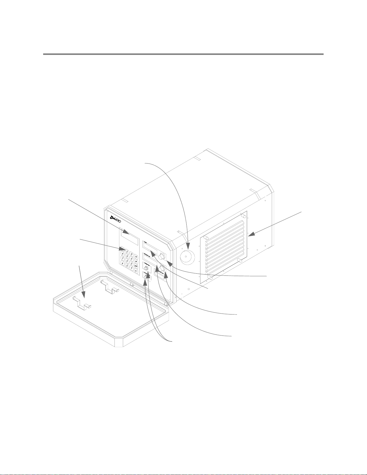
• Transmitter Base unit (see Figure 2-1)
• Transmitter anteena Kit (see Figure 2-7).
You must supply an external AC power source with either 120 VAC at 60 Hz
or 220 VAC at 50 Hz. SpectraWave 1900 parts are described in the sections
that follow.
For Future Use
4 x 20 LCD Display
Keypad
Power cord
storage
Air Filter
Power Output
Control Knob
Power
Output Display
Channel/Frequency
Knob
Channel/Frequency
Status Lights
Display
Figure 2-1 The SpectraWave 1900 Transmitter Base Unit
The SpectraWave 1900 transmitter base unit operates through screens,
subscreens, and a keypad on the front panel of the transmitter. The front panel
has two large 1 x 8 character liquid crystal displays (LCDs) that display
frequency and power values, a TX Power LED, a System Power LED, and a 4
x 20 character LCD where the screens and subscreens are displayed.
2 - 2
Refer to Appendix A for information on part numbers for SpectraWave
models, options, and accessories.
Page 11
2.2 User Interface
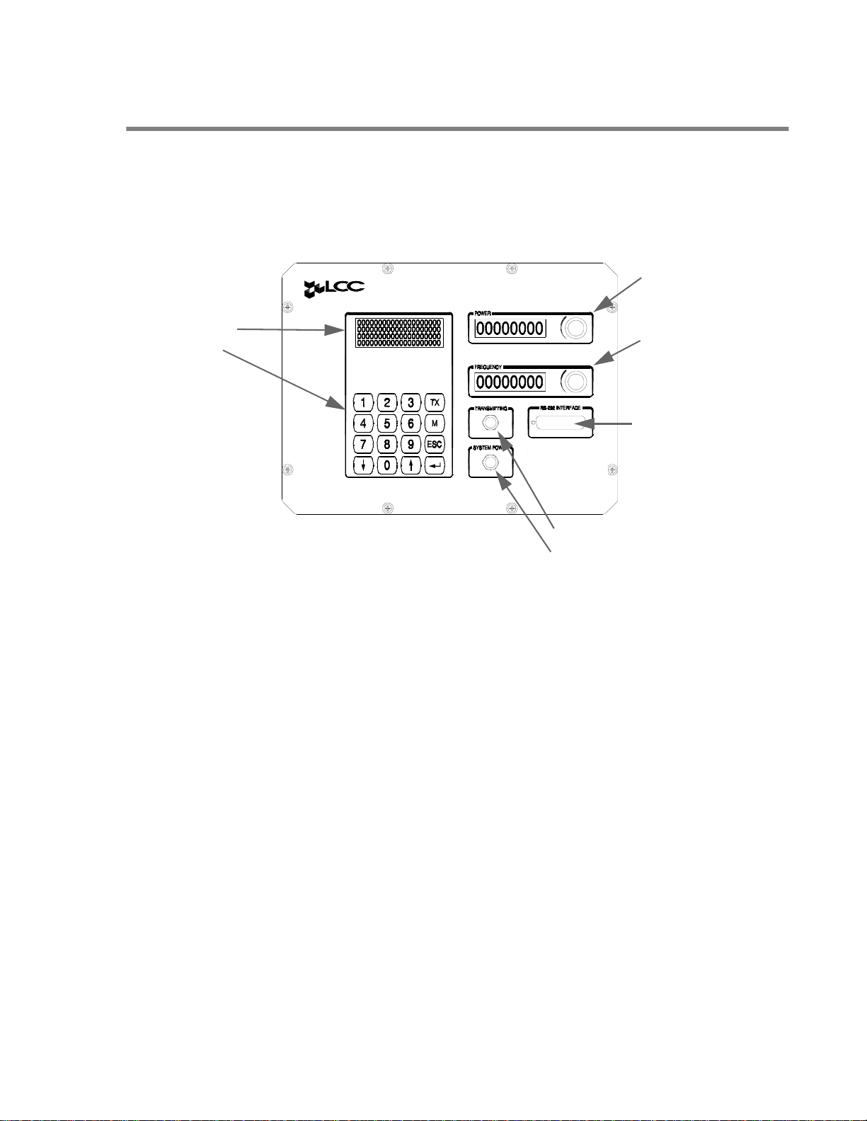
SpectraWave 1900’s Base Unit’s front panel provides a control interface for
transmitter operation (see Figure 2-2).
2.2 User Interface
Power LCD Display
and Control Knob
LCD Display
and Keypad
Frequency LCD
Display and Control
Knob
RS-232
Interface
Connection
TRANSMITTING and
POWER Status Lights
Figure 2-2 SpectraWave 1900 Front Panel
The front panel presents two LCD displays that enable the user to configure
and control SpectraWave 1900’s operation:
• Menu-Driven Screens, configured via an associated keypad; and
• Numerical Screens, configured via associated knobs, and providing an
alternate method to configure power and frequency values.
Additionally, status lights provide operating information.
2.2.1 Menu-Driven Screens Display
Use the menu-driven screens display and associated 16-key keypad to
configure SpectraWave 1900 operations.
Use the 10 numeric keys to select between available menu options and to enter
transmitting and power values. (Transmitting and power values can also be
entered via the numeric displays and associated control knobs.)
Use the up and down arrow keys to select available menu options.
2 - 3
Page 12

SpectraWave 1900 Basics
Use the four remaining, non-numeric keys to perform these functions,
available from most menu screens:
SpectraWave 1900’s user control interface embodies menu-driven functional
screens that are accessible from one another in a specific sequence. The
functional screens are accessible via a Main Menu, displayed by pressing the
M key. The Main Menu screen enables access to three associated menus (see
Figure 2-3).
• Press TX to commence transmitting on a selected frequency or channel
number.
• Press M to display the Main Menu screen.
• Press ESC to leave one screen and return to the previous screen, or to
reenter a value or parameter already entered into SpectraWave 1900.
• Press 8 to accept a value or parameter newly entered into SpectraWave
1900.
Main Menu Screen
Setup
Menu
Screen
Figure 2-3 Main Menu Screen and Associated Menus
The Setup Menu provides access to seven functional screens (see Figure 2-4).
Diagnostics
Menu
Screen
Status
Menu
Screen
2 - 4
Page 13
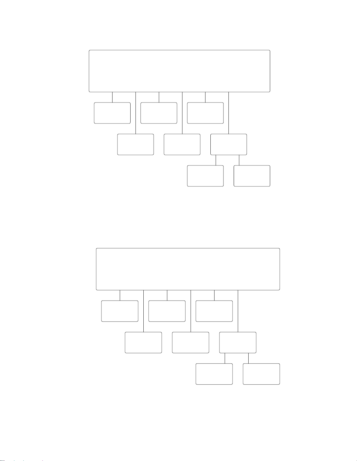
Setup Menu
Screen
2.2.1 Menu-Driven Screens Display
Protocol
Screen
Screen
Clock
Freq/Chan
Screen
LCD
Screen
Power
Screen
Cbl Loss
Screen
More
Ant Gain
Screen
Figure 2-4 Setup Menu and Associated Functional Screens
The Diagnostics Menu provides access to seven functional screens (see Figure
2-5).
Diagnostics Menu
Screen
Error Log
Screen
Synth
Screen
Power Amp
Screen
Temp
Screen
Voltages
Screen
Down Load
Screen
More
Unit Info
Screen
Figure 2-5 Diagnostics Menu and Associated Functional Screens
The Status Menu provides access to the Status Screen (see Figure 2-6).
2 - 5
Page 14

SpectraWave 1900 Basics
See later sections of this manual for guidance on using and configuring
SpectraWave 1900’s functional screens.
Status Menu
Screen
Status
Screen
Figure 2-6 Status Menu and Associated Screen
2.2.2 Numerical Screens (Power and Frequency)
The two numerical screens and associated control knobs provide an alternate
method of setting transmitter Power and Frequency values. Rotate the control
knob(s) clockwise to increase or counterclockwise to decrease the displayed
value(s).
2.2.3 Status Lights
SpectraWave 1900’s front panel includes two status lights, green and red:
green when the unit is transmitting, and red when the unit is powered on.
2.2.4 Antenna Accessory Kit
The antenna kit contains a 6 dB gain omni-directional antenna, three ten-foot
cable sections, a tripod, and a dummy load. The dummy load terminates the
output of an external power meter while performing system VSWR
measurements. Different antenna accessory kits are available for PCS,
DCS-1800, AMPS and N-AMPS, iDEN, ETACS, and GSM protocols.
Note: The PCS antenna kit is the only kit designed to operate with the SpectraWave
1900.
2 - 6
Page 15
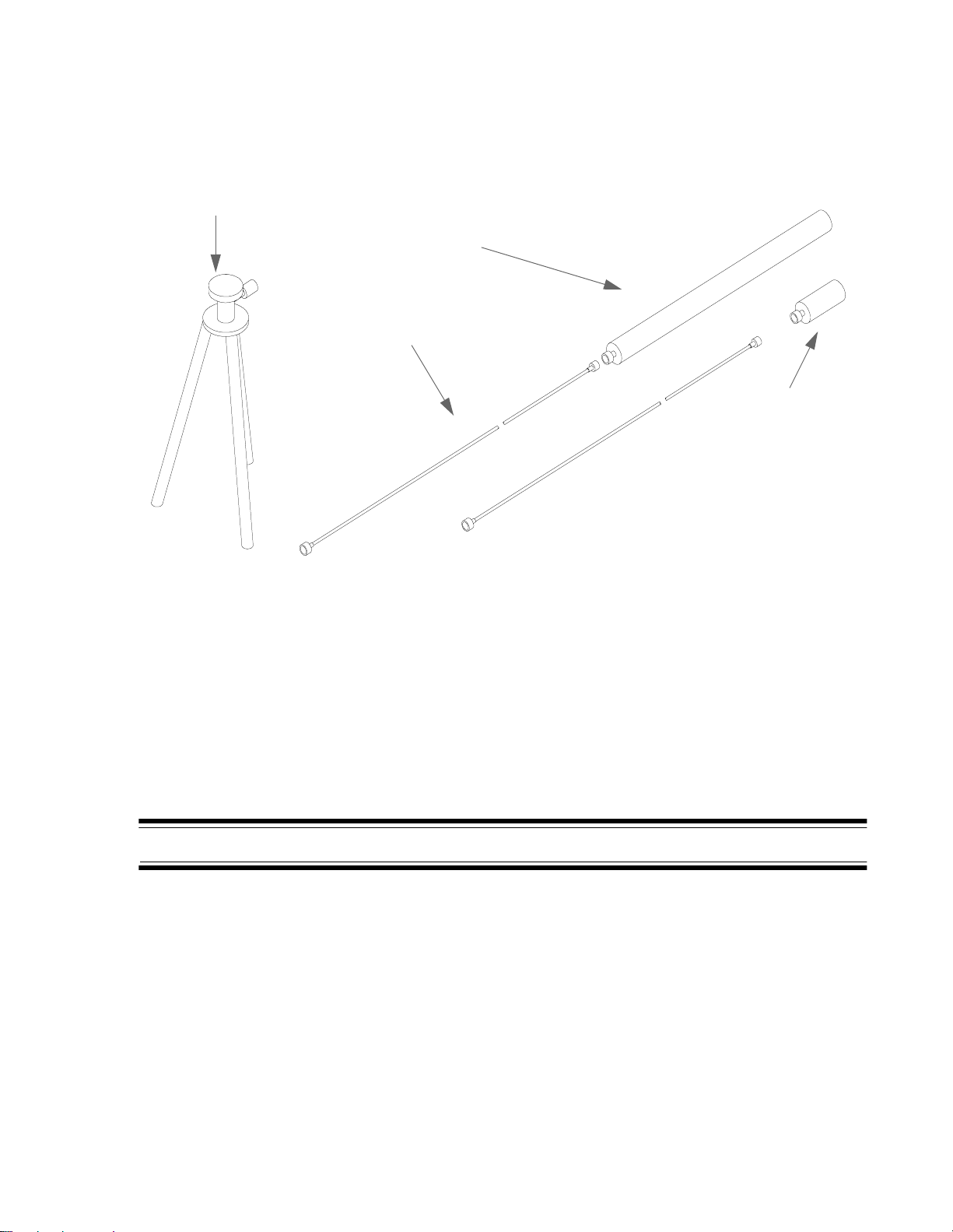
Figure 2-7 shows an example of a SpectraWave 1900 transmitter antenna kit.
Optional antenna
tripod
2.2.5 Tripod
Antenna
One of three
Transmitter
Cables
Dummy
Load
Figure 2-7 Transmitter Antenna Kit
The SpectraWave 1900 Transmitter comes with three cables and any adaptors
required for attachment to the main RF antenna. An optional antenna tripod is
also available.
2.2.5 Tripod
An optional light-weight tripod is available from LCC. This tripod is designed
for mounting the antennas that come with the unit.
WARNING!: Use caution when using tripod in high winds.
2.2.6 Transmitter Power Supply
Three types of power cables are available:
• U.S. style,
• U.K. style, and
• Euro-style.
2 - 7
Page 16

SpectraWave 1900 Basics
The power cable attaches to the rear panel of the transmitter. Plug the power
cable into the power source. The power source can be either 110 VAC, 60Hz or
220 VAC, 50Hz nominal. The SpectraWave 1900 transmitter will
automatically switch to support either power source.
2 - 8
Page 17

2.3 SpectraWave 1900 Convenience Features
2.3 SpectraWave 1900 Convenience Features
SpectraWave 1900 is designed to operate in almost any environment where an
antenna can be located, and is ready to use less than three minutes after you
turn it on. Other convenience features of SpectraWave 1900 include:
• Power output displayed in watts, milliwatts, or dBm
• Strong casing and structure to withstand harsh environments, including
shock and vibration
• Small size and weight (approximately 12.5" x 18.5" x 10" and just over
35 pounds) for moving the unit around a variety of testing locations
• Carrying handle
• Lift rings for use with cranes or lifting ropes.
2 - 9
Page 18

SpectraWave 1900 Basics
2.4 Preparing SpectraWave 1900 for Operation
Before you begin testing, you must properly prepare and set up the
SpectraWave 1900. The following sections describe the steps and precautions
you should perform to ensure proper setup and accurate operation.
2.4.1 Checking and Maintaining the Air Filter
WARNING!: Before operating the SpectraWave 1900 transmitter, verify that
the air filter is clean. The air filter must be cleaned every 30
days to ensure safe operation of the transmitter.
To clean the air filter:
1. Loosen the four captive panel fasteners that hold the air filter in
place (see Figure 2-1). Remove the cover.
2. Remove the filter and wash it with warm, soapy water . Let the filter
air dry.
3. T o reinstall the air filter , insert the filter into the transmitter with the
wire diamond mesh over the filter media facing away from you (the
filter cover screws are offset, making it impossible to install upside
down).
4. Replace the filter cover over the filter and tighten the four captive
panel fasteners by hand.
If the air filter is damaged or torn, you may need to replace it with a new air
filter. Refer to Appendix A for information on ordering a new air filter.
WARNING!: Reattach the front cover to the SpectraWave unit before you
begin drive testing to guard against harsh or inclement weather.
2 - 10
Page 19
2.4.2 Setting Up the SpectraWave 1900
Radio Tower
2.4.2 Setting Up the SpectraWave 1900
Once you have decided upon your test site, follow these steps to set up
SpectraWave 1900:
1. Set up the main RF antenna in a position that provides an unobstructed
view of the intended coverage area. The usual setup requires a tripod
for temporary mounting and to raise the antenna over any roof parapets.
Note: Note that structures behind and to the side of the antenna will
strongly affect the radiation pattern, a situation common to working
with rooftop antennas.
2. Connect one or more RF antenna cables between the antenna and the
RF output connector on the side of the SpectraWave1900 unit. If more
than one RF cable is needed, use the supplied N-female to N-female
adaptors to connect cables together.
3. Configure the SpectraWave setup so that the lowest point on the
antenna cable(s) is lower than the connection to the SpectraWave.
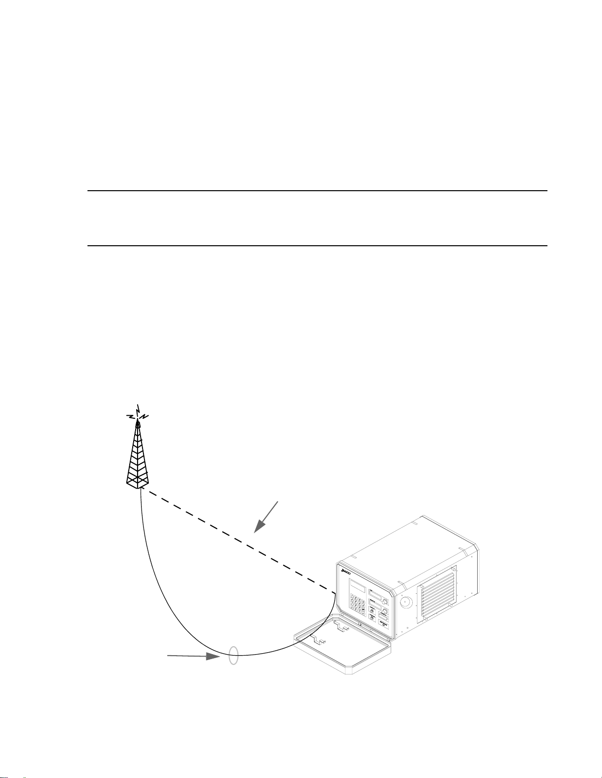
4. Route the antenna cable to provide a drip loop. This drip loop will
protect against accidental shock (see Figure 2-8).
Antenna Site
Unsafe cable setup:
moisture will
accumulate towards
transmitter
SpectraWave
1900
Safe cable setup
with drip loop
Figure 2-8 SpectraWave Setup (not to scale)
2 - 11
Page 20

SpectraWave 1900 Basics
WARNING!: Water runoff along the antenna cable can create electrical
hazard.
5. Check the air filter to make sure it is clean. If the filter is dirty, remove
it and clean it before turning the power switch on. Refer to section
2.4.1, Checking and Maintaining the Air Filter for instructions on
removing and cleaning the air filter.
6. Connect the power cable to the rear panel. Connect the power cable to
your external AC power source, such as an existing power outlet. For
locations lacking power outlets, use an AC power generator .Turn on the
power switch. Whenever the power is turned on, make sure that the unit
is properly ventilated. Allow clearance for air intake on the side. Also
allow clearance for the exhaust vent on the rear panel.
WARNING!: Do not allow the AC Power Cord to lie in water . This can create
danger of electrical shock.
7. Set the test parameters as shown in Chapter 3. You now are ready to begin testing.
2.4.3 Setting Test Parameters
To prepare for testing, read the instructions in Chapter 4, Functional screens.
Follow these instructions to set up the test parameters and begin drive testing.
2 - 12
Page 21

2.5 Preparing SpectraWave 1900 for Shipping
2.5 Preparing SpectraWave 1900 for Shipping
Should you need to ship SpectraWave 1900 for any reason, make sure that you
pack the unit in its original packing carton. Failure to do so may cause damage
to the unit that is not covered by the LCC warranty.
2 - 13
Page 22

SpectraWave 1900 Basics
2 - 14
Page 23

Quick Start
Follow the steps below to perform basic SpectraW ave 1900 operations on
an already placed system. Refer to later sections of this manual for
details on more complex operations, technical data, and guidance in the
use of optional peripherals.
This section provides basic guidance on:
• Powering up the SpectraWave 1900 transmitter
• Accessing and using the SpectraWave 1900 transmitter’s
functional screens.
This chapter assumes that the SpectraWave 1900 transmitter has been set
up correctly and has power available to it.
This chapter is organized according to the SpectraWave 1900’s menu
structure. Functional screens are grouped with the menus associated with
them. Start with section 3.1, Powering Up SpectraWave 1900.
3
Figure 3 - 0:
Go to section 3.2, Status Menu Screen, and then to section 3.3, Setup
Menu Screen.
In section 3.3, Setup Menu Screen, go to the desired screen sections:
• 3.3.1, Protocol Screen
• 3.3.2, Frequency/Channel Screen
• 3.3.3, Power Screen
• 3.3.4, Clock Setup Screen
• 3.3.5, LCD Contrast Setup Screen
• 3.3.6, Setup Menu-2 Screen.
Go to section 3.4, Diagnostics Menu Screen, and then to the desired
screen sections:
• 3.4.1, Error Log View/Log Screen
• 3.4.2, Power Amp Status Screen
• 3.4.3, Voltage Status Screen
• 3.4.4, Synthesizer Status Screen
• 3.4.5, Ambient Temperature Screen.
Go to section 3.5, Setting Up an PCS 1900 Protocol, for a sample step-
by-step procedure using SpectraWave 1900.
Page 24
3.1 Powering Up SpectraWave 1900
3.1 Powering Up SpectraWave 1900
To power up the SpectraWave 1900 transmitter:
1. Connect the antenna and press the power switch on the back of the
SpectraWave 1900 transmitter. The SpectraWave 1900 transmitter will
activate, and the fan will run.
2. The LCC Copyright screen (see Figure 3-1) displays on the
SpectraWave’s Main LCD Display while the transmitter warms up,
followed by the Status Menu screen (see Figure 3-2).
.
C
Copyright 1997,LCCI
The Versio n Number
identifies the firmware
version installed.
Transmitter
Serial #
T
SpectraWave 1900
M
Ver. X.XX xxxx
Running--Diagnostics
Figure 3-1 LCC Copyright Screen
Est.EIRP : 23.0 dBi
PCS 1900 Chan#:511 F
Not Transmitting
1.Setup Menu
3 - 2
Figure 3-2 Status Menu Screen
Page 25

3.2 Status Menu Screen
The Status Menu screen (see Figure 3-2) displays when the transmitter is
completely warmed up.
The Status Menu screen displays:
• Effective Isotropic Radiated Power (EIRP)
• Protocol selected (PCS-1900 in this example)
• Channel number (Chan #)
• Direction of the channel (F for forward, R for reverse)
Press 1 to display the Setup Menu screen (see Figure 3-3).
3.3 Setup Menu Screen
3.2 Status Menu Screen
Access the Setup Menu screen (see Figure 3-3) as follows:
•Press 1 on the Status Menu screen, or
•Press 1 on the Main Menu screen.
S E T U P M E N U
1.PROTOCOL 4.CLOCK
2.FREQ/CHAN 5.LCD
Ä
3.POWER .More
Figure 3-3 Setup Menu Screen
To use the Setup Menu Screen, press the corresponding number to go to
the following functional screens:
•Press 1 to display the Protocol screen (section 3.3.1).
•Press 2 to display the Frequency/ Channel screen (section 3.3.2).
•Press 3 to display the Power screen (section 3.3.3).
•Press 4 to display the Clock Setup screen (section 3.3.4).
3 - 3
Page 26

3.3.1 Protocol Screen
•Press 5 to display the LCD Contrast Setup screen (section 3.3.6).
•Press i to access the Setup Menu-2 screen (section 3.3.6).
3.3.1 Protocol Screen
To use the Protocol screen:
1. From the Setup Menu screen (see Figure 3-3), press 1 to access the
Protocol screen (see Figure 3-4).
P R O T O C O L
Curr Prot= PCS 1900
1.PCS1900 3.IS136
2.PCS50 4.CDMA
Figure 3-4 Protocol Page One Screen
2. Press the corresponding number to select one of the following from the
Protocol Screen:
•Press 1 to display the PCS 1900 screen
(GSM Protocol of the PCS band).
•Press 2 to display the PCS 50 screen
(an LCC channel assignment scheme to match an EXP-2001
receiver, using the same channels in the PCS band).
•Press 3 to display the IS 136 screen
(the TIA/EIA IS-136 standard for the PCS band).
•Press 4 to display CDMA screen
(the TIA/EIA IS-95 standard for the PCS band).
3 - 4
Page 27

3.3.2 Frequency/Channel Screen
To use the Frequency/Channel screen:
1. From the Setup Menu screen (see Figure 3-3), press 2 to access the
Frequency/Channel screen (see Figure 3-5).
FREQUENCY/CHANNEL#
1.FREQ(MHz) PCS 1900
2.CHANNEL FORWARD
3.3.2 Frequency/Channel Screen
ESC.Prev Menu
Figure 3-5 Frequency/Channel Screen
2. Press the corresponding number to select either the Frequency Range
screen or Channel Range screen:
•Press 1 to display the Frequency Range screen.
•Press 2 to display the Channel Range screen.
3 - 5
Page 28

3.3.3 Power Screen
3.3.3 Power Screen
To use the Power screen:
1. From the Setup Menu screen, press 3 to access the Power Level Range
screen (see Figure 3-6).
POWER LEVEL RANGE
1.milliWatts 30-999
2.Watts 0.1-20
3.dBm 15-43
Figure 3-6 Power Level Range Screen
2. Press the corresponding number on the Power Level Range screen to
select the desired output power level:
•Press 1 for milliwatts.
•Press 2 for watts.
•Press 3 for dBm.
3. Press ESC to return to the Setup Menu screen.
3 - 6
Page 29

3.3.4 Clock Setup Screen
To use the Clock Setup screen:
1. From the Setup Menu screen, press 4 to access the Time and Date
Menu Screen (see Figure 3-7).
TIME AND DATE MENU
Time HH:MM PM
Date MM/DD/YYYY DAY
1.Setup ESC.Prv Menu
3.3.4 Clock Setup Screen
Figure 3-7 Time and Date Menu Screen
2. Press 1 to display the Clock Setup screen.
3. Press ESC to return to the Time and Date Menu screen. Press ESC
again to return to the Setup Menu screen.
3 - 7
Page 30

3.3.5 LCD Contrast Setup Screen
3.3.5 LCD Contrast Setup Screen
To use the LCD Contrast Setup screen:
1. From the Setup Menu screen, press 5 to access the LCD Contrast Setup
screen (see Figure 3-8).
LCD CONTRAST SETUP
1.MAIN LCD DISPLAY
2.POWER & FREQ LCDs
ESC. Prev Menu
Figure 3-8 LCD Contrast Setup Screen
2. Press the corresponding number to setup the desired LCD Contrast
screen:
•Press 1 to view the Main LCD Display screen.
•Press 2 to display the Power & Frequency LCD screen.
3. Press ESC to return to the LCD Contrast screen.
4. Press ESC again to return to the Setup Menu screen.
3 - 8
Page 31

3.3.6 Setup Menu-2 Screen
To use the Setup Menu-2 screen:
1. From the Setup Menu Page One screen, press i to access the Setup
Menu-2 screen (see Figure 3-9).
S E T U P M E N U-2
1.CBL LOSS
2.ANT GAIN
3.3.6 Setup Menu-2 Screen
ESC.Prev Menu
Figure 3-9 Setup Menu-2 screen
2. Press the corresponding number to go to the following functional
screens:
•Press 1 to display the Cable Loss screen.
•Press 2 to display the Antenna Gain screen.
3. Press ESC to return to the Setup Menu-2 screen.
4. Press ESC again to return to the Setup Menu screen.
3 - 9
Page 32

3.3.6 Setup Menu-2 Screen
3.3.6.1 Cable Loss Screen
To use the Cable Loss screen:
1. From the Setup Menu screen, press i to access Setup Menu-2 screen
(see Figure 3-9).
2. Press 1 on the Setup Menu-2 screen to access the Cable Loss screen
(see Figure 3-10).
CABLE LOSS
Curr Loss= 1.0dB
Enter Loss in dB
Î
.Accept ESC.PrvMenu
Figure 3-10 Cable Loss Screen
3. On the Cable Loss screen, enter the Cable Loss value (a positive
number between 0 and 23 dB).
4. Press 8 to enter the cable loss value.
5. Press ESC to return to the Setup Menu-2 screen, then press ESC again
to return to the Setup Menu screen.
3 - 10
Page 33

3.3.6.2 Antenna Gain Screen
To use the Antenna Gain screen:
1. From the Setup Menu screen, press i to access Setup Menu-2 screen.
2. Press 2 on the Setup Menu-2 screen (see Figure 3-9) to access the
Antenna Gain screen (see Figure 3-11).
Antenna GAIN
Curr Gain=1.1dBi
Enter Gain in dBi
3.3.6 Setup Menu-2 Screen
Î
.Accept ESC.PrvMenu
Figure 3-11 Antenna Gain Screen
3. Enter the Antenna Gain value on the Antenna Gain screen. This value
will be a positive number.
Note: An Antenna Gain that is specified in dBi (gain relative to a half-wave
dipole) will be 1.7dB lower than the equivalent dBi value.
4. Press 8 to enter the antenna gain value.
5. Press ESC to return to the Setup Menu-2 screen, then press ESC again
to return to the Setup screen.
6. Press i on the front panel keypad to return to the Main Menu screen.
3 - 11
Page 34

3.4 Diagnostics Menu Screen
3.4 Diagnostics Menu Screen
To access the Diagnostics Menu screen (see Figure 3-12):
1. From the Main Menu screen, press 2 on the front panel keypad to
display the Diagnostics Menu screen (see Figure 3-12).
DIAGNOSTICS MENU
1.ERROR LOG 4.SYNTH
2.POWER AMP 5.TEMP
Ä
3.VOLTAGES .More
Figure 3-12 Diagnostics Menu Screen
To use the Diagnostics Menu screen, press the corresponding number to
go to the following functional screens:
•Press 1 to display the Error Log screen.
•Press 2 to display the Power Amp screen.
•Press 3 to display the Voltages screen.
•Press 4 to display the Synthesizer screen.
•Press 5 to display the Temperature screen.
•Press i to display the Diags Menu-2 screen.
3 - 12
Page 35

3.4.1 Error Log View/Log Screen
To use the Error Log View/Log screen:
1. From the Diagnostics Menu screen (see Figure 3-12), press 1 to access
the Error Log V iew/Clear screen. The Error Log View/Clear screen will
appear (see Figure 3-13).
ERROR LOG VIEW/CLEAR
1.VIEW ERROR LOG
2.CLEAR ERROR LOG
ESC.Prev Menu
3.4.1 Error Log View/Log Screen
Figure 3-13 Error Log View/Clear Screen
2. Press 1 to display the View Error Log screen. One of two screens will
display: Figure 3-15 if there were no errors logged, and Figure 3-16 if
there were errors logged (see Appendix B for an explanation of error
codes in the log).
There were no Errors
Logged / The LOG was
cleared.
Press a key to cont.
Figure 3-14 No Errors Logged screen
3 - 13
Page 36
3.4.1 Error Log View/Log Screen
E7 @ 5:27PM 10/20
End of Log
.Move ESC.Prv Menu
3. Press 2 to display the Clear Error Log screen (see Figure 3-16).
Figure 3-15 Error Log
Do you really want
to Clear? Clear LOG
cannot be undone.
Î
.YES ESC.NO
Figure 3-16 Clear Error Log Screen
4. Press 8 to clear the error log. The Diagnostics Menu screen will
appear (see Figure 3-12). Verify that the voltage supply is within
5. Press ESC to return to Error Log View/Clear screen.
3 - 14
Page 37

3.4.2 Power Amp Status Screen
To use the Power Amp Status screen:
1. From the Diagnostics Menu screen, press 2 to verify that the Power
Amp is operating correctly . The Power Amp Status screen displays (see
Figure 3-17). Use this screen to verify that the voltage supply is within
specifications, and the Power Amp is not drawing too much current.
POWER AMP STATUS
Power Amp +28V:OK
PA Current:OK
Ä
3.4.2 Power Amp Status Screen
.More ESC.Prev Menu
Figure 3-17 Power Amp Status Screen
2. Press i on the front panel keypad to verify the power amplifier’s base
temperature. The PA Temperature screen displays (see Figure 3-18).
PA Temperature
Power Amp Base Temp
is 35.6 C(96.0 F)
Press ESC to cont.
Figure 3-18 PA Temperature Screen
3. Press ESC to return to the Diagnostics Menu screen.
3 - 15
Page 38

3.4.3 Voltage Status Screen
3.4.3 Voltage Status Screen
To use the Voltage Status screen:
1. From the Diagnostics menu, press 3 to access the Voltage Status screen
(see Figure 3-19). Use this screen to verify that all the other voltages
used within the SpectraWave 1900 are within specifications.
VOLTAGE STATUS
+5V Supply:OK
+12V Supply:OK
ESC.Prev. Menu
Figure 3-19 Voltage Status Screen
2. Press ESC to return to the Diagnostics Menu screen.
3 - 16
Page 39

3.4.4 Synthesizer Status Screen
To use the Synthesizer Status screen:
1. From the Diagnostics menu, press 4 to access the Synthesizer Status
screen. When not transmitting, the screen looks like Figure 3-20.
SYNTHESIZER STATUS
Synthesizer is
Not Locked
Press ESC to cont.
3.4.4 Synthesizer Status Screen
Figure 3-20 Synthesizer Status screen (not transmitting)
When transmitting, the screen looks like Figure 3-21.
SYNTHESIZER STATUS
Synthesizer is
Locked @ 1930.00 MHz
Press ESC to cont.
Figure 3-21 Synthesizer Status screen (transmitting)
2. Press ESC to return to the Diagnostics Menu screen.
3 - 17
Page 40

3.4.5 Ambient Temperature Screen
3.4.5 Ambient Temperature Screen
To use the Ambient Temperature screen:
1. From the Diagnostics Menu screen, press 5 to access the Ambient
Temperature screen (see Figure 3-22). Verify the temperature within
the SpectraWave case.
AMBIENT TEMPERATURE
Inside Temperature
is 22.5 C(72.5 F)
Press ESC to cont.
Figure 3-22 Ambient Temperature Screen
2. Press ESC to return to the Diagnostics Menu screen.
3 - 18
Page 41

3.4.6 Diagnostics Menu-2 Screen
To access the Diags Menu-2 screen:
1. From the Diagnostics Menu screen, press i to access the Diags Menu-2
screen (see Figure 3-23).
D I A G S M E N U-2
1.DOWN LOAD 3.RF MDM
2.UNIT INFO
ESC. Prev Menu
3.4.6 Diagnostics Menu-2 Screen
Figure 3-23 Diags Menu-2 Screen
2. From the Diags Menu-2 screen:
•Press 1 to access the Download screen.
•Press 2 to access the Unit Info screen.
3. Press ESC to return to the Diagnostics Menu screen.
3 - 19
Page 42
3.5 Setting Up a PCS 1900 Protocol
3.5 Setting Up a PCS 1900 Protocol
The following PCS-1900 protocol uses steps and techniques common to
other transmission protocols. Use it as an example of SpectraWave 1900
operation.
1. Place the SpectraWave 1900 in the desired testing location.
2. Turn the power switch to the OFF position, then attach the power cable
to the back of the SpectraWave 1900.
3. Connect the antenna (or dummy load) to the left side of the
SpectraWave 1900.
4. Press the power switch on the back of the SpectraW ave 1900 to turn the
transmitter on. The system power light on the front panel lights.
5. The LCC Copyright screen appears (see Figure 3-24) on the
Spectra Wave 1900’s Main LCD Display while the transmitter warms
up.
The Version Number
identifies the firmware
version installed.
C
Copyright 1997,LCCI
T
SpectraWave 1900
M
Ver. X.XX xxxx
Running--Diagnostics
Figure 3-24 LCCI Copyright Screen
6. After the transmitter is warmed up and ready, the Status Menu screen
displays (Figure 3-26).
Transmitter
Serial #
3 - 20
Page 43

3.5 Setting Up a PCS 1900 Protocol
Est.EIRP : 23.0 dBi
PCS1900 Chan#: 511 F
Not Transmitting
1.Setup Menu
Figure 3-25 Status Menu Screen
7. Press M on the front panel keypad to access the Main Menu screen (see
Figure 3-26).
M A I N M E N U
1. SETUP MENU
2. DIAGNOSTICS
3. STATUS MENU
Figure 3-26 Main Menu Screen
8. Press 1 on the front panel keypad to access the Setup Menu screen (see
Figure 3-27) to set up the clock and LCD displays.
3 - 21
Page 44

3.5 Setting Up a PCS 1900 Protocol
S E T U P M E N U
1.PROTOCOL 4.CLOCK
2.FREQ/CHAN 5.LCD
Ä
3.POWER .More
Figure 3-27 Setup Menu Screen
9. Press 4 on the front panel to access the Time and Date Menu screen
(see Figure 3-28).
TIME AND DATE MENU
Time HH:MM PM
Date MM/DD/YYYY DAY
3 - 22
1.Setup ESC.Prv Menu
Figure 3-28 Time and Date Menu Screen
10. Verify that the time and date are correct. If so, press ESC to return to
previous screen and proceed to step 19. If not, follow steps 11 through
18.
11. Press 1 on the front panel to set up the Time and Date. The Clock Setup
screen (see Figure 3-29) displays.
Page 45

3.5 Setting Up a PCS 1900 Protocol
C L O C K S E T U P
Time HH:MM PM
Date MM/DD/YYYY DAY
Î
.Accept ESC.PrvMenu
Figure 3-29 Clock Setup Screen
12. Use the front panel keypad to enter the hour and minutes into the
SpectraWave 1900.
13. Use the up and down arrow on the front panel keypad to select AM or
PM. Use the numerical key pad to enter the time. The new hour and
minutes will appear on the Clock Setup screen time line.
14. After setting the time, press 1 to set the date. The cursor will move to
the Date line on the Clock Setup screen.
15. Use the front panel keypad to enter the month, day, year (in numerals)
and the day (in characters).
16. Use the up and down arrows on the front panel keypad to select the day
of the week. The new month, day , and year will appear on the date line.
17. Press 8 on the front panel keypad to enter the new time and date into
the SpectraWave 1900. The Time Updated screen will momentarily
appear (see Figure 3-31). The Setup Menu screen will then return.
3 - 23
Page 46

3.5 Setting Up a PCS 1900 Protocol
C L O C K S E T U P
Time HH:MM PM
Date MM/DD/YYYY Day
Time & Date updated!
Figure 3-30 Time Updated screen
18. Press 5 to setup the desired LCD display contrast. The LCD Contrast
Setup screen (see Figure 3-31) appears.
LCD CONTRAST SETUP
1.MAIN LCD DISPLAY
2.POWER & FREQ LCDs
ESC.Prev Menu
Figure 3-31 LCD Contrast Setup Screen
19. Press 1 to set up the Main LCD Display. The Main LCD Display screen
(see Figure 3-32) appears.
3 - 24
Page 47

3.5 Setting Up a PCS 1900 Protocol
Ä
Ä
MAIN LCD DISPLAY
Ä
.Lighter .Darker
078%
Î
.Accept ESC.PrvMenu
Figure 3-32 Main LCD Display screen
20. Use the up and down arrows on the front panel keypad to select the desired contrast.
21. Press 8 to accept the desired display contrast. The LCD Contrast
Setup Screen (see Figure 3-31) appears.
22. Press 2 to set up the Power & Frequency LCD display. The Power and
Frequency LCD screen appears (see Figure 3-33).
POWER AND FREQ LCDs
Ä
.Lighter .Darker
078%
Î
.Accept ESC.PrvMenu
Figure 3-33 Power and Frequency LCD’s Display Screen
23. Use the up and down arrows to select the desired display contrast.
24. Press 8 to accept the new display contrast. The LCD Contrast Setup
screen appears.
25. Press M to display the Main Menu screen (see Figure 3-34).
3 - 25
Page 48

3.5 Setting Up a PCS 1900 Protocol
M A I N M E N U
1. SETUP MENU
2. DIAGNOSTICS
3. STATUS MENU
Figure 3-34 Main Menu Screen
26. Press 2 to access the Diagnostics Menu screen (see Figure 3-35) to
verify the operation of the SpectraWave 1900.
DIAGNOSTICS MENU
1.ERROR LOG 4.SYNTH
2.POWER AMP 5.TEMP
Ä
3.VOLTAGES .More
Figure 3-35 Diagnostics Menu Screen
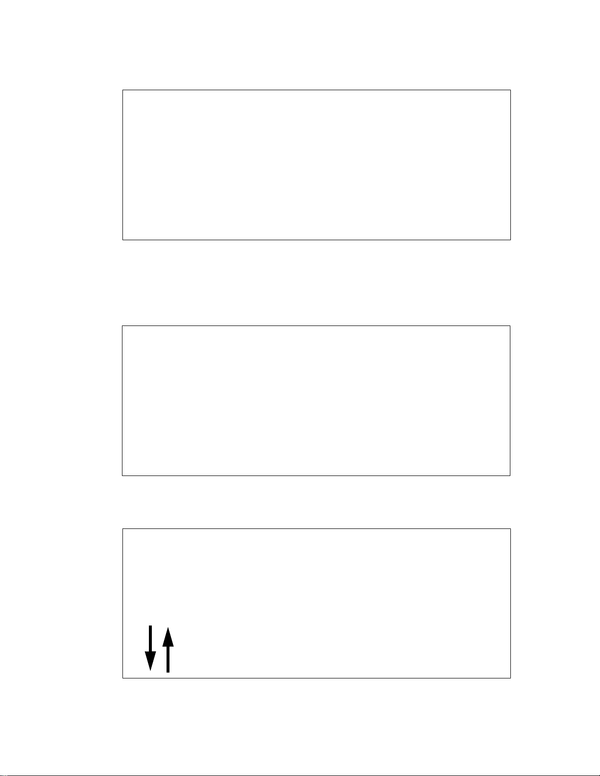
27. Press 1 to access the Error Log View/Clear screen (see Figure 3-36).
View errors as required.
3 - 26
Page 49
3.5 Setting Up a PCS 1900 Protocol
Ä
ERROR LOG VIEW/CLEAR
1.VIEW ERROR LOG
2.CLEAR ERROR LOG
ESC.Prev Menu
Figure 3-36 Error Log View/Clear Screen
28. Press 1 to display the View Error Log screen. One of two screens will
display: Figure 3-38 if no errors were logged, and Figure 3-39 if errors
were logged.
There were no Errors
Logged / The LOG was
cleared.
Press a key to cont.
Figure 3-37 No Errors Logged screen
E7 @ 5:27PM 10/20
End of Log
.Move ESC.Prv Menu
Figure 3-38 Error Log screen
3 - 27
Page 50

3.5 Setting Up a PCS 1900 Protocol
29. From the No Errors Logged screen press any key to continue. From the
Error log screen press ESC to return to the previous screen.
30. Press 1 to access the Error Log View/ Clear screen.
31. Press 2 to access the Clear Error Log screen (see Figure 3-39).
Do you really want
to Clear? Clear LOG
cannot be undone.
Î
.YES ESC.NO
Figure 3-39 Clear Error Log Screen
32. Press 8 to clear the error log. The Diagnostics Menu screen redisplays.
DIAGNOSTICS MENU
1.ERROR LOG 4.SYNTH
2.POWER AMP 5.TEMP
Ä
3.VOLTAGES .More
Figure 3-40 Diagnostics Menu Screen
33. Press 2 to verify that the Power Amplifier is operating correctly. The
Power Amp Status screen (see Figure 3-41) appears.
3 - 28
Page 51

3.5 Setting Up a PCS 1900 Protocol
POWER AMP STATUS
Power Amp +28V:OK
PA Current:OK
Ä
.More ESC.Prev Menu
Figure 3-41 Power Amp Status Screen
34. Verify that the Power Amp Status reads as illustrated.
35. Press i to verify that the Power Amps Base Temp is operating within
the unit’s Operational Specifications (see Appendix A). The PA
Temperature screen appears (see Figure 3-42).
PA Temperature
Power Amp Base Temp
is 35.6 C(96.0 F)
Press ESC to cont.
Figure 3-42 PA Temperature Screen
36. Press ESC to return to the Diagnostics Menu screen.
37. Press 3 to verify that the SpectraWave 1900’s power supply is operating
correctly. The Voltage Status screen (see Figure 3-43) appears.
3 - 29
Page 52

3.5 Setting Up a PCS 1900 Protocol
VOLTAGE STATUS
+5V Supply:OK
+12V Supply:OK
ESC.Prev Menu
Figure 3-43 Voltage Status Screen
38. Verify that the +5V Supply and +12V Supply lines read OK.
39. Press ESC to return to the Diagnostics Menu screen.
40. From the Diagnostics Menu screen, press 5 to verify that the internal
temperature of the SpectraWave 1900 is within the Unit’s Operations
Specifications (see Appendix A). The Ambient Temperature screen
appears (see Figure 3-44).
AMBIENT TEMPERATURE
Inside Temperature
is 22.5 C(72.5 F)
Press ESC to cont.
Figure 3-44 Ambient Temperature Screen
41. Press ESC to return to the Diagnostics Menu screen.
3 - 30
Page 53

3.5 Setting Up a PCS 1900 Protocol
42. Press ESC to return to the Status Menu screen. The S tatus Menu screen
appears (see Figure 3-45).
Est.EIRP : 23.0 dBi
PCS1900 Chan#: 511 F
Not Transmitting
1.Setup Menu
Figure 3-45 Status Menu Screen
43. Press 1 to access the Setup Menu screen (see Figure 3-46).
S E T U P M E N U
1.PROTOCOL 4.CLOCK
2.FREQ/CHAN 5.LCD
Ä
3.POWER .More
Figure 3-46 Setup Menu Screen
3 - 31
Page 54

3.5 Setting Up a PCS 1900 Protocol
44. Press 1 to access the Protocol screen. The Protocol screen appears (see
Figure 3-47).
P R O T O C O L
Curr Prot= PCS 1900
1.PCS 1900 3.IS136
2.PCS 50 4.CDMA
Figure 3-47 Protocol Screen
45. Select a protocol. The Protocol Selected screen then displays (figure 3-48).
PROTOCOL SELECTED
PCS1900 Selected
Î
.Accept ESC.Reenter
Figure 3-48 Protocol Selected Screen
46. Press 8 to accept the PCS 1900 protocol. The Frequency/Channel #
screen appears (see Figure 3-49).
3 - 32
Page 55

3.5 Setting Up a PCS 1900 Protocol
FREQUENCY/CHANNEL#
1.FREQ(MHz) PCS1900
2.CHANNEL FORWARD
ESC.Prev Menu
Figure 3-49 Frequency/Channel # Screen
47. To enter a desired channel number into the SpectraWave 1900, go to
step 51. Steps 48 through 50 describe how to enter a frequency number.
48. Press 1 to enter a frequency number into the SpectraWave 1900. The
Frequency Range screen appears (see Figure 3-50).
PCS 1900 FREQ RANGE
Forward 1930-1990
Reverse 1850-1910
Î
.Accept ESC.PrvMenu
Figure 3-50 PCS 1900 Frequency Range Screen
49. Use the keypad or Frequency MHz knob to enter a desired frequency,
which appears in the frequency channel display.
50. Press 8 to select the desired frequency entered into the SpectraWave
1900. The Setup Menu screen redisplays.
51. Press 2 to enter the desired channel number into the SpectraW ave 1900.
The Frequency/Channel # screen appears (see Figure 3-51).
3 - 33
Page 56

3.5 Setting Up a PCS 1900 Protocol
PCS 1900 CHAN# RANGE
1.Forward 511-811
2.Reverse 511-811
ESC. Prev Menu
Figure 3-51 PCS 1900 Chan # Range Screen
52. Select 1 for forward or 2 for reverse to enter the direction of the
channel.
53. Use the keypad or Frequency MHz knob to enter a desired channel,
which appears in the Frequency/Channel display.
54. Press ESC to accept the channel entered.
55. From the Setup Menu, press 3 on the front panel keypad to select
the desired power output level. The Power Level Range screen
appears (see Figure 3-52).
POWER LEVEL RANGE
1.milliWatts 30-999
2.Watts 0.1-20
3.dBm 15-43
Figure 3-52 Power Level Range screen
56. T o enter the desired power unit: select 1 for milliWatts, 2 for Watts, and 3 for dBm.
3 - 34
57. Use the keypad or Power knob to enter a desired power output
level, which appears in the power display.
Page 57

3.5 Setting Up a PCS 1900 Protocol
58. Press 8 to accept the power output level into the SpectraWave
1900. The Setup Menu screen appears.
59. Press i to access the Setup Menu-2 screen (see Figure 3-53).
S E T U P M E N U-2
1.CBL LOSS
2.ANT GAIN
ESC.Prev Menu
Figure 3-53 Setup Menu-2 Screen
60. Press 1 on the front panel keypad to enter the value of the cable loss
into the SpectraWave 1900. The Cable Loss screen appears (see
Figure 3-54).
CABLE LOSS
Curr Loss=1.0dB
Enter Loss in dB
Î
.Accept ESC.PrvMenu
Figure 3-54 Cable Loss screen
61. Use the keypad or Power knob to enter a desired value of cable loss,
a positive number between 0 and _db.
62. Press 8 to accept the value of the cable loss into the SpectraWave
1900. The Setup Menu-2 screen redisplays.
63. Press 2 to enter the value of Antenna Gain into the SpectraWave
1900. The Antenna Gain Menu screen appears (see Figure 3-55).
3 - 35
Page 58

3.5 Setting Up a PCS 1900 Protocol
Antenna GAIN
Curr Gain=1.6dBi
Enter Gain in dBi
Î
.Accept ESC.PrvMenu
Figure 3-55 Antenna Gain Screen
64. Use the keypad to enter a desired value of antenna gain in dBi.
65. Press 8 to accept the value of antenna gain into the SpectraWave
1900. The Setup Menu-2 screen redisplays.
CAUTION: An output power error will occur if the output power falls below
15 < Power Level + Cable Loss — Antenna Gain < = 46.
66. Press M to access the Main Menu screen.
67. Press 3 to access the status screen to verify the output power level
of the SpectraWave 1900.
68. Press TX to start the SpectraWave 1900 transmitting. The
transmitting light (green) on the front panel turns on.
69. Close and lock the front panel cover of the SpectraWave 1900 and start collecting data.
70. To stop transmitting open the front panel cover of the
SpectraWave 1900, press TX on the keypad and turn the power off.
3 - 36
Page 59
Functional Screens
The V
Figure 4 - 0:
SpectraWave 1900 menus have three major areas of functionality:
• Setup,
• Diagnostic, and
• Status functions.
SpectraWave 1900 functions originate primarily from a Main Menu and other
menu screens, including the Setup Menu, Setup-2, Diagnostics Menu, Diags-2,
and Status Menu screens.
This chapter uses three sections to describe SpectraW ave 1900’s major areas of
functionality. Section 3.1 describes the Setup functions and screens. Section
3.2 describes the Diagnostics functions and screens. Section 3.3 describes the
Status functions and screens. Each section contains detailed steps for
performing each function and using each screen.
4
Note: Follow the steps provided in this chapter only after you have properly
positioned the transmitter, connected the components, and powered up
SpectraWave 1900.
ersion Number
identifies the firmware
version installed.
Transmitter
C
Serial #
Copyright 1997,LCCI
T
SpectraWave 1900
M
Ver. X.XX xxxx
Running--Diagnostics
Figure 4-1 LCC Copyright Screen
Page 60

Functional Screens
Est.EIRP : 23.0 dBi
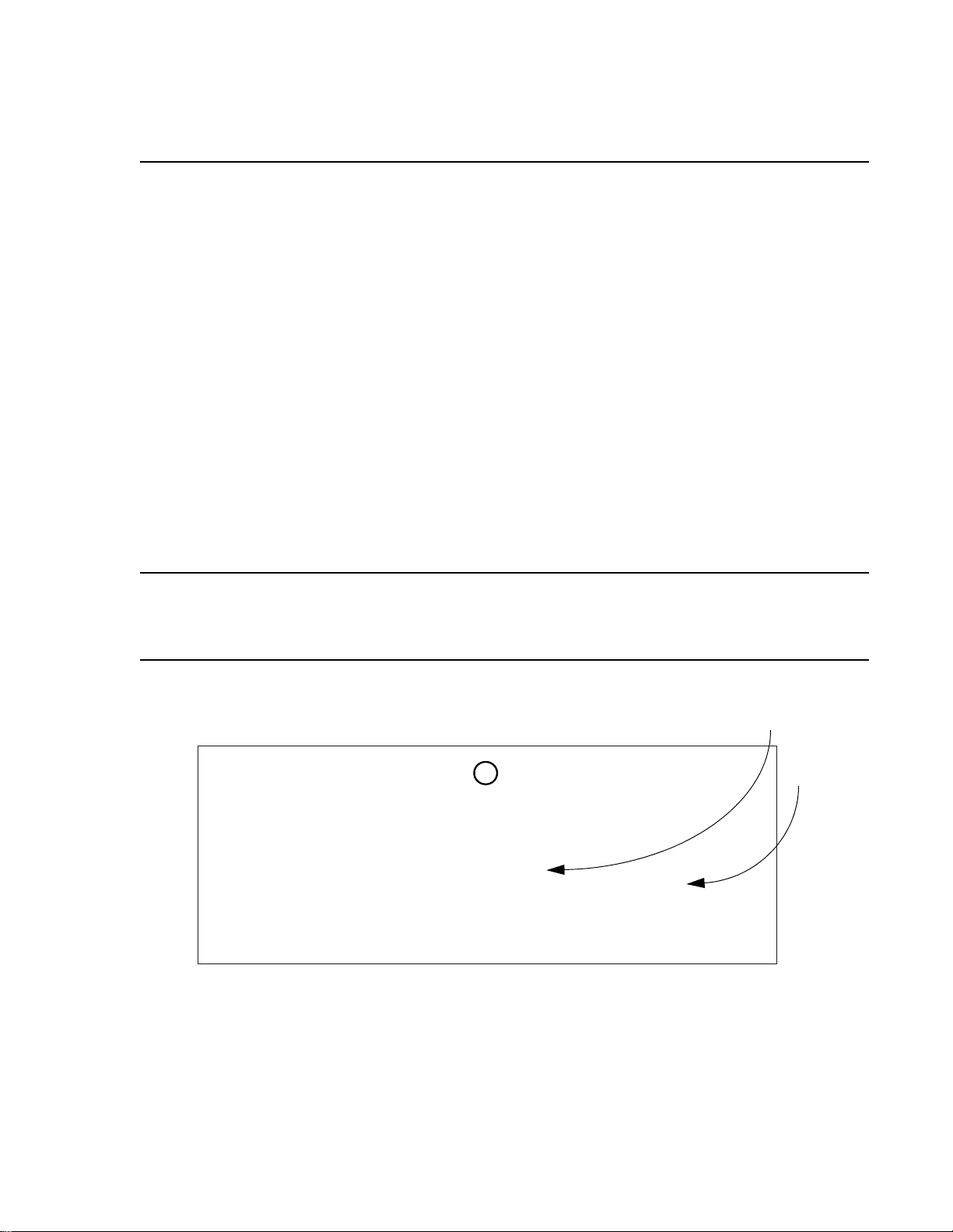
When you first turn on SpectraWave 1900, the LCC copyright screen displays
(see Figure 4-1), followed by the Status Menu screen (see Figure 4-2) after the
transmitter finishes warming up. From the Status Menu screen, you can move
to the Setup Menu screen, or you can move to the Main Menu screen by
pressing M on the front keypad. From the Main Menu screen, you can access
three menu screens by pressing the corresponding number on the keypad:
• 1. Setup Menu,
• 2. Diagnostics Menu, and
• 3. Status Menu.
Access the Setup-2 screen from the Setup Menu screen and the Diags-2 screen
from the Diagnostics Menu screen.
PCS 1900 Chan#: 511 F
Not Transmitting
1.Setup Menu
Figure 4-2 Status Menu Screen
M A I N M E N U
1. SETUP MENU
2. DIAGNOSTICS
3. STATUS MENU
4 - 2
Figure 4-3 Main Screen Menu
Page 61

4.1 Using Setup Functions
This section offers instructions on performing SpectraWave 1900 setup
functions. Before you begin performing these steps, make sure you have
properly positioned the transmitter, connected the components, and powered
up SpectraWave 1900. For information on how to do this, refer to section 2.1
Basic Transmitter Configuration.
When the transmitter is fully warmed up, the Status Menu screen displays. On
the Status Menu screen, press 1 to access the Setup Menu screen (see
Figure 4-4).
S E T U P M E N U
1.PROTOCOL 4.CLOCK
4.1 Using Setup Functions
2.FREQ/CHAN 5.LCD
3.POWER .More
Figure 4-4 Setup Menu Screen
4.1.1 Selecting Protocol
To use the Protocol screen:
1. From the Setup Menu screen, press 1 to select Protocol. The Protocol
screen appears (see Figure 4-5).
2. Protocols are listed on the Protocol screen. Select a protocol by
pressing the corresponding number. If you do not see the protocol you
want to select listed on the Protocol screen, press i to display the
Protocol-2 screen (see Figure 4-6), where other protocols are listed.
Ä
4 - 3
Page 62

Functional Screens
P R O T O C O L
Curr Prot= PCS 1900
1.PCS 1900 3.IS136
2.PCS50 4.CDMA
Figure 4-5 Protocol Screen
3. After you select a protocol, the Protocol Selected screen appears (see
Figure 4-7) with the selected protocol shown. Press 8 to accept the
protocol; the Frequency/Channel # screen appears (see Figure 4-8)
displaying the selected protocol.
Note: The Frequency/Channel # screen also is accessible by pressing 2 on
the Setup Menu screen.
PROTOCOL SELECTED
PCS1900 Selected
Î
.Accept ESC.Reenter
Figure 4-6 Protocol Selected Screen
4 - 4
Page 63

4.1.2 Selecting Frequency and Channel Number
FREQUENCY/CHANNEL#
1.FREQ(MHz) CDMA
2.CHANNEL FORWARD
ESC.Prev Menu
Figure 4-7 Frequency/Channel # Screen
4.1.2 Selecting Frequency and Channel Number
To use the Frequency/Channel # screen:
1. Press 1 on the Frequency/Channel # screen to change the frequency.
The Freq Range screen appears (see Figure 4-9). On the Freq Range
screen, select the frequency using the keypad or knob control. When
you are finished, press 8 . The Frequency/Channel # screen is
displayed.
PCS 1900 FREQ RANGE
Fwd. 1930-1990
Rev. 1850-1910
Î
.Accept ESC.PrvMenu
Figure 4-8 Freq Range Screen
2. Press 2 on the Frequency/Channel # screen to display the Channel #
Range screen (see Figure 4-10). On the Channel # Range screen, select
1 or 2 to select the channel direction (Forward and Reverse). Use the
keypad or Power Control knob to select the desired channel number.
The 8 function now displays. Press 8 to enter the data. The Setup
Menu screen is redisplayed.
4 - 5
Page 64

Functional Screens
PCS1900 CHAN# RANGE
1.Forward 511-811
2.Reverse 511-811
Î
.Accept ESC.PrvMenu
Figure 4-9 Chan # Range Screen
4.1.3 Selecting Power
To adjust the power levels on the SpectraWave 1900:
1. From the Setup Menu screen, press 3 to select Power . The Power Level
Range screen will appear (see Figure 4-11).
2. From the Power Level Range screen, press 1, 2, or 3 to select the
desired power units, then use the keypad or Power Output Control knob
to select the desired power level. The 8 function is now available (see
Figure 4-11). When you are finished, press 8 . The Setup Menu screen
is redisplayed.
POWER LEVEL RANGE
1.milliWatts 30-999
2.Watts 0.1-20
3.dBm 15-43
Figure 4-10 Power Level Range Screen
4 - 6
Page 65

1.milliWwatts 30-999
2.Watts 0.1-20
3.dBm 15-43
Î
.Accept ESC.PrvMenu
Figure 4-11 Power Level Range Screen
4.1.4 Setting the Clock and Date
To adjust the time and date:
4.1.4 Setting the Clock and Date
1. From the Setup Menu screen, press 4 to select Clock. The Time and
Date Menu screen will appear (see Figure 4-12).
TIME AND DATE MENU
Time HH:MM PM
Date MM/DD/YYYY DAY
1.Setup ESC.Prv Menu
Figure 4-12 Time and Date Menu Screen
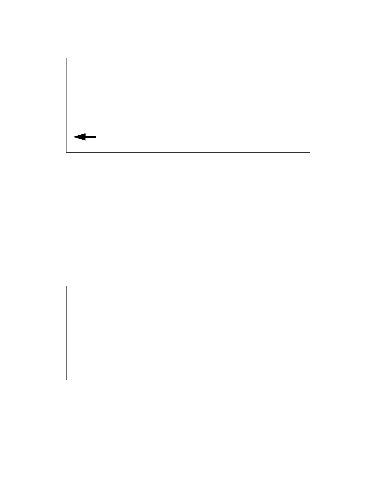
2. From the Time and Date Menu screen, press 1 for Setup. The Clock
Setup screen will appear (see Figure 4-13). Set the time using the
keypad. Use the up and down arrows to select AM or PM. When you
finish changing the time, press 1 to change the date. Use the keypad to
change the date. Use the up and down arrows to change the day of the
week. When you are finished, press 8 to accept the changes. The Time
and Date updated screen will momentarily be displayed. The Setup
Menu screen is then redisplayed.
4 - 7
Page 66
Functional Screens
C L O C K S E T U P
Time 12:31 PM
Date 06/12/1997 THU
.Accept ESC.PrvMenu
Figure 4-13 Clock Setup Screen
4.1.5 Setting the LCD Contrast
To adjust the LCD contrast setting:
1. From the Setup Menu screen, press 5 to select LCD. The LCD Contrast
Setup screen appears (see Figure 4-14).
2. From the LCD Contrast Setup screen, press 1 or 2 to select the Main
LCD Display (see Figure 4-15) or Power and Freq LCDs screen (see
Figure 4-16). Use the up and down arrows to adjust the setting. When
you are finished, press 8 . Press ESC to return to the LCD Contrast
Setup screen.
LCD CONTRAST SETUP
1.MAIN LCD DISPLAY
2.POWER & FREQ LCDs
ESC. Prev Menu
Figure 4-14 LCD Contrast Setup Screen
4 - 8
Page 67

4.1.6 Setting Cable Loss Value
Ä
Ä
MAIN LCD DISPLAY
Ä
.Lighter .Darker
063%
Î
.Accept ESC.PrvMenu
Figure 4-15 Main LCD Display screen
POWER AND FREQ LCDs
Ä
.Lighter .Darker
063%
Î
.Accept ESC.PrvMenu
Figure 4-16 Power and Freq Screen
4.1.6 Setting Cable Loss Value
The cable loss and antenna gain values are used to set the desired output
power, or effective radiated power (refer to section 4.1.3, Selecting Power). If
the combination of cable loss, antenna gain, and desired output power is lower
or higher than the range of the SpectraWave 1900, you will receive an error
message.
4 - 9
Page 68

Functional Screens
S E T U P M E N U-2
1.CBL LOSS 3.RF MDM
2.ANT GAIN
ESC. Prev Menu
1. Display the Setup Menu Page One screen and press i to display the
Setup Menu-2 screen (see Figure 4-17).
Figure 4-17 Setup Menu-2 Screen
2. On the Setup Menu-2 screen, press 1 to display the Cable Loss screen
(see Figure 4-18).
CABLE LOSS
Curr Loss=1.0dB
Enter Loss in dB
Î
.Accept ESC.PrvMenu
Figure 4-18 Cable Loss Screen
3. On the Cable Loss screen, use the keypad or Power Control knob to set
the cable loss dB. When you are finished, press 8 . The Setup Menu-2
screen displays.
4 - 10
Page 69

4.1.7 Setting Antenna Gain Value
To set the antenna gain value:
1. On the Setup Menu-2 screen, press 2 to display the Antenna Gain
screen (see Figure 4-19).
Antenna GAIN
Curr Gain= 1.6dBi
Enter Gain in dBi
Î
.Accept ESC.PrvMenu
4.1.7 Setting Antenna Gain Value
Figure 4-19 Antenna Gain Screen
2. On the Antenna Gain screen, use the keypad or Power Control knob to
set the antenna gain strength. When you are finished, press 8 . The
Setup Menu-2 screen is displayed.
4 - 11
Page 70

Functional Screens
4.2 Using the Diagnostic Functions
This section offers instructions on performing SpectraWave 1900 diagnostic
functions. Before you begin performing these steps, make sure you have
properly positioned the transmitter, connected the components, and powered
up SpectraWave 1900. For information on how to do this, refer to section 2.3
Preparing SpectraWave 1900 for Testing.
Following are basic steps for using SpectraWave 1900’s diagnostic
capabilities.
1. Press M to display the Main Menu.
2. Press 2 to display the Diagnostics Menu screen (see Figure 4-20).
DIAGNOSTICS MENU
1.ERROR LOG 4.SYNTH
2.POWER AMP 5.TEMP
Ä
3.VOLTAGES .More
Figure 4-20 Diagnostics Menu screen
From the Diagnostics Menu screen, select the diagnostic characteristics you
want to view (Error Log, Power Amp, Voltages, Synthesizer, or Temp) by
pressing the corresponding number. Pressing i displays Diags Menu-2 screen
(see Figure 4-21). The options on the Diags Menu-2 are Down Load and Unit
Info. Pressing ESC returns you to the previous menu.
4 - 12
Page 71

4.2.1 Displaying the Error Log View/Clear
D I A G S M E N U-2
1.DOWN LOAD 3.RF MDM
2.UNIT INFO
ESC. Prev Menu
Figure 4-21 Diags Menu-2
4.2.1 Displaying the Error Log View/Clear
To display the error log:
1. Press 1. The Error Log View/Clear screen appears (see Figure 4-22).
ERROR LOG VIEW/CLEAR
1.VIEW ERROR LOG
2.CLEAR ERROR LOG
ESC.Prev menu
Figure 4-22 Error Log View/Clear Screen
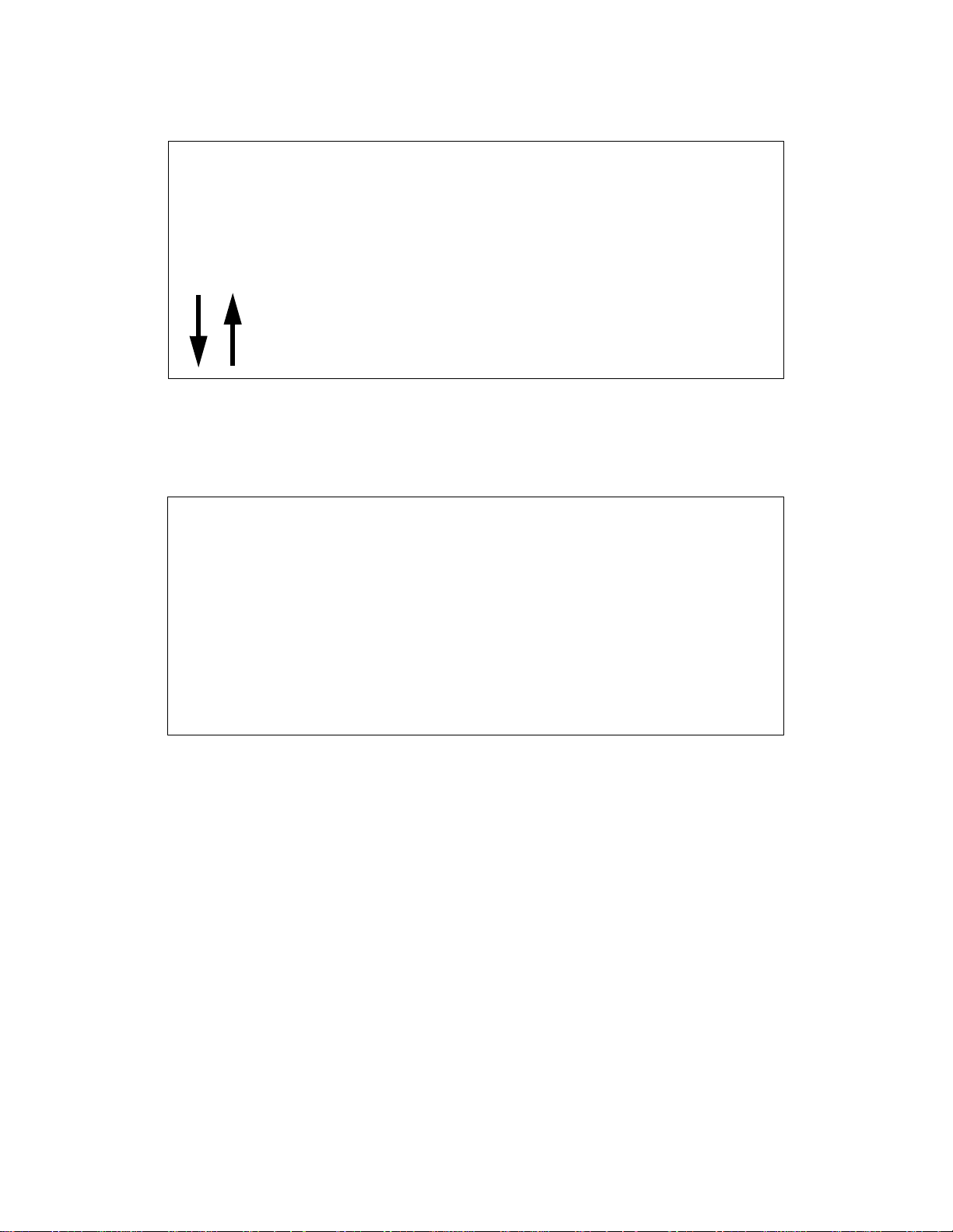
2. Press 1 on the Error Log View/Clear screen to view the error log. One
of two screens appear: the Error Log screen (see Figure 4-23) or the No
Errors Logged screen (see Figure 4-24). Use the arrow keys to view the
error log messages. Press ESC to return to the Error Log View/Clear
screen.
4 - 13
Page 72
Functional Screens
E7 @ 5:27PM 10/20
End of Log
.Move ESC.Prv Menu
Figure 4-23 Error Log
There were no Errors
Logged / The LOG was
cleared.
Press a key to cont.
Figure 4-24 No Errors Logged screen
3. To clear the error log, press 2 on the Error Log V i ew/Cle ar scree n. The
Clear Error Log screen will appear (see Figure 4-25). Press 8 to clear
the error log. Press ESC if you do not want to clear the error log and
you will return to the Error Log V iew/Clear screen. Press ESC to return
to the Diagnostic Menu screen.
4 - 14
Page 73

Do you really want
to Clear? Clear LOG
cannot be undone.
Î
.YES ESC.NO
Figure 4-25 Clear Error Log Screen
4.2.2 Viewing the Power Amp Status
To view the power amp status:
4.2.2 Viewing the Power Amp Status
1. Press 2 on the Diagnostics Menu screen to display the Power Amp
Status screen (see Figure 4-26).
POWER AMP STATUS
Power Amp +28V:OK
PA Current:OK
Ä
.More ESC.Prev Menu
Figure 4-26 Power Amp Status Screen
2. On the Power Amp Status screen, press i to display the PA
Temperature screen (see Figure 4-27). Verify the PA temperature is
within specifications (see Appendix A), press ESC to return to the
Diagnostics Menu screen.
4 - 15
Page 74

Functional Screens
PA Temperature
Power Amp Base Temp
is 35.6 C(96.0 F)
Press ESC to cont.
Figure 4-27 PA Temperature Screen
4.2.3 Viewing Voltage Status
To view the voltage status:
1. Press 3 on the Diagnostics Menu screen to display the Voltage Status
screen (see Figure 4-28). Verify the status of the +5 volt and +12 volt
power supply, press ESC to return to the Diagnostics Menu screen.
VOLTAGE STATUS
+5V Supply:OK
+12V Supply:OK
ESC. Prev. Menu
Figure 4-28 Voltage Status Screen
4 - 16
Page 75

4.2.4 Viewing Synthesizer Status
To view the synthesizer status:
1. Press 4 on the Diagnostics Menu screen to view the synthesizer status.
When transmitting, the Synthesizer Status screen in Figure 4-29
appears; when not transmitting, the Synthesizer Screen in Figure 4-30
appears. After you have viewed the status of the synthesizer, press ESC
to return to the Diagnostics Menu screen.
SYNTHESIZER STATUS
Synthesizer is
Locked @ 1930.40 MHz
4.2.4 Viewing Synthesizer Status
Press ESC to cont.
Figure 4-29 Synthesizer Status Screen (transmitting)
SYNTHESIZER STATUS
Synthesizer is
Not Locked
Press ESC to cont.
Figure 4-30 Synthesizer Status Screen (not transmitting)
4 - 17
Page 76

Functional Screens
4.2.5 Viewing Ambient Temperature Status
To view the ambient temperature status:
1. Press 5 on the Diagnostics Menu screen to view the ambient
temperature status. The Ambient Temperature screen will appear (see
Figure 4-30).
AMBIENT TEMPERATURE
Inside Temperature
is 22.5 C(72.5 F)
Press ESC to cont.
Figure 4-31 Ambient Temperature Screen
2. After you have viewed the temperature information, press ESC to
return to the Diagnostics Menu screen.
4.2.6 Viewing Transmitter Information
To view transmitter information:
1. On the Diags Menu-2 screen, press 2 to display the first SpectraWave
Info screen (see Figure 4-32).
SpectraWave INFO
Model: 1900
FW Ver: (1.05P) 3.14A
Ä
.More ESC.Prev Menu
4 - 18
Figure 4-32 SpectraWave Info Screen
Page 77

4.2.6 Viewing Transmitter Information
2. View the transmitter information, then press i to display the second
SpectraWave Info screen (see Figure 4-33).
SpectraWave INFO
Tx S/N: P0432
PA S/N: P0001
ESC. Prev Menu
Figure 4-33 SpectraWave Info Screen
3. After you have viewed the serial number of the transmitter and the
power amp, press ESC to return to the first SpectraWave Info screen.
Press ESC again to return to the Diags Menu-2 screen.
4 - 19
Page 78

Functional Screens
4.3 Using Status Menu Options
This section contains information on SpectraWave 1900 status options.
The following are basic steps for using SpectraWave 1900’s status capabilities.
1. Press M to display the Main Menu.
2. Press 3 to display the Status Menu screen (see Figure 4-39).
Est.EIRP : 23.0 dBi
PCS 1900 Chan#:511 F
Not Transmitting
1.Setup Menu
Figure 4-34 Status Menu Screen
3. View the estimated EIRP, the selected protocol, channel number,
direction of the channel, and whether the transmitter is transmitting to
not transmitting. Press 1 to access the Setup Menu screen. Refer to
section 4.1, Using Setup Functions for information on how to use the
Setup Menu.
4 - 20
Page 79

Appendix A Specifications
SpectraWave Models Available
Model Frequency Range Part Number
SpectraWave 1900 1850 to 1990 MHz 41-A00818-1
SpectraWave 1800 1710 to 1880 MHz 41-A01059-1
SpectraWave 800 805 to 960 MHz 41-A01026-1
Performance Specifications
Output Power (Selectable in 0.1 dBm increments)
SpectraWave 1900 30 mw to 20W (+15 to +43 dBm)
SpectraWave 1800 30 mw to 25W (+15 to +44 dBm)
SpectraWave 800 30 mw to 40W (+15 to +46 dBm)
Output Power Accuracy +/-1 dBm over full temperature range
Frequency Accuracy 0.5 PPM
Harmonics >-60 dBc
Warm Up Time maximum of 3 minutes
Input Power 110 VAC 60 Hz or 220 VAC 50Hz
Output Connectors RF output: N-type, female
Physical Specifications
Size 12.5"Wx18.5"Lx10"H (32cmX51cmX25cm)
Weight <40 lbs (18 kg)
Operating Temperature -4 to +140F (-20 to +60C)
Operating Humidity Range 10 to 95%, non-condensing
Modem output: SMA female with male center
P/U (Reserved for future use)
External inputs: DB25 female
Page 80

Appendix A Specifications
User Interface
Key Features
• Two large 1 x 8 character LCDs display power and frequency settings
• 4 x 20 character LCD provides menu selectable operation
• Separate power and frequency control knobs
• Numeric key pad
• Transmit and power ON/OFF LEDs.
• Continuous wave (analog) transmitter
• Wireless remote control option
• Protocol selection provides automatic channel number selection and
spacing for each technology
• Power output selectable in watts, milliwatts, or dBm, in 0.1 dB increments
• Automatic power control and temperature compensation
Accessories
• Advanced thermal design for use in all climates
• Heavy duty external case with an isolated internal chassis to protect
against shock and vibration
• Air filter, sealed front panel, and rear cover for moisture and dirt resistance
• Built-in self-test to log, display, and shut down the unit when errors
occur
• Downloadable firmware and modular construction for fast upgrades
and easy service
• Retractable lift rings.
Accessory Part Number
Model 1900 Antenna Accessory Kit 41-A01104-1
Cable, Superflex, 1/4", 10 ft long, quantity: 3 70192
Omnidirectional antenna, 3 dB gain 17888
Dummy Load, 50 OHM (Alan Industries) 50LH50
A-2
Cable Connector, quantity: 2, (M/A COM) 3080-0000-00
Page 81

Accessory Part Number
Model 1800 Antenna Accessory Kit 43-A01103-1
Cable, Superflex, 1/4", 10 ft long, quantity: 3 70192
Omnidirectional antenna, 3 dB gain 17888
Dummy Load, 50 OHM (Alan Industries) 50LH50
Cable Connector, quantity: 2, (M/A COM) 3080-0000-00
Model 800 Antenna Accessory Kit 42-A01101-1
(AMPS, NAMPS, iDEN, ESMR)
Cable, Superflex, 1/4", 10 ft long, quantity: 3 70192
Omnidirectional antenna, 3 dB gain, 806-869 Mhz 17888
Dummy Load, 50 OHM (Alan Industries) 50LH50
Cable Connector, quantity: 2, (M/A COM) 3080-0000-00
Model 800 Antenna Accessory Kit 42-A01101-1
(GSM, ETACS)
Cable, Superflex, 1/4", 10 ft long, quantity: 3 70192
Omnidirectional antenna, 3 dB gain, 890-960 Mhz 17888
Dummy Load, 50 OHM (Alan Industries) 50LH50
Cable Connector, quantity: 2, (M/A COM) 3080-0000-00
Antenna Tri-pod 63835
A-3
Page 82

Appendix A Specifications
A-4
Page 83
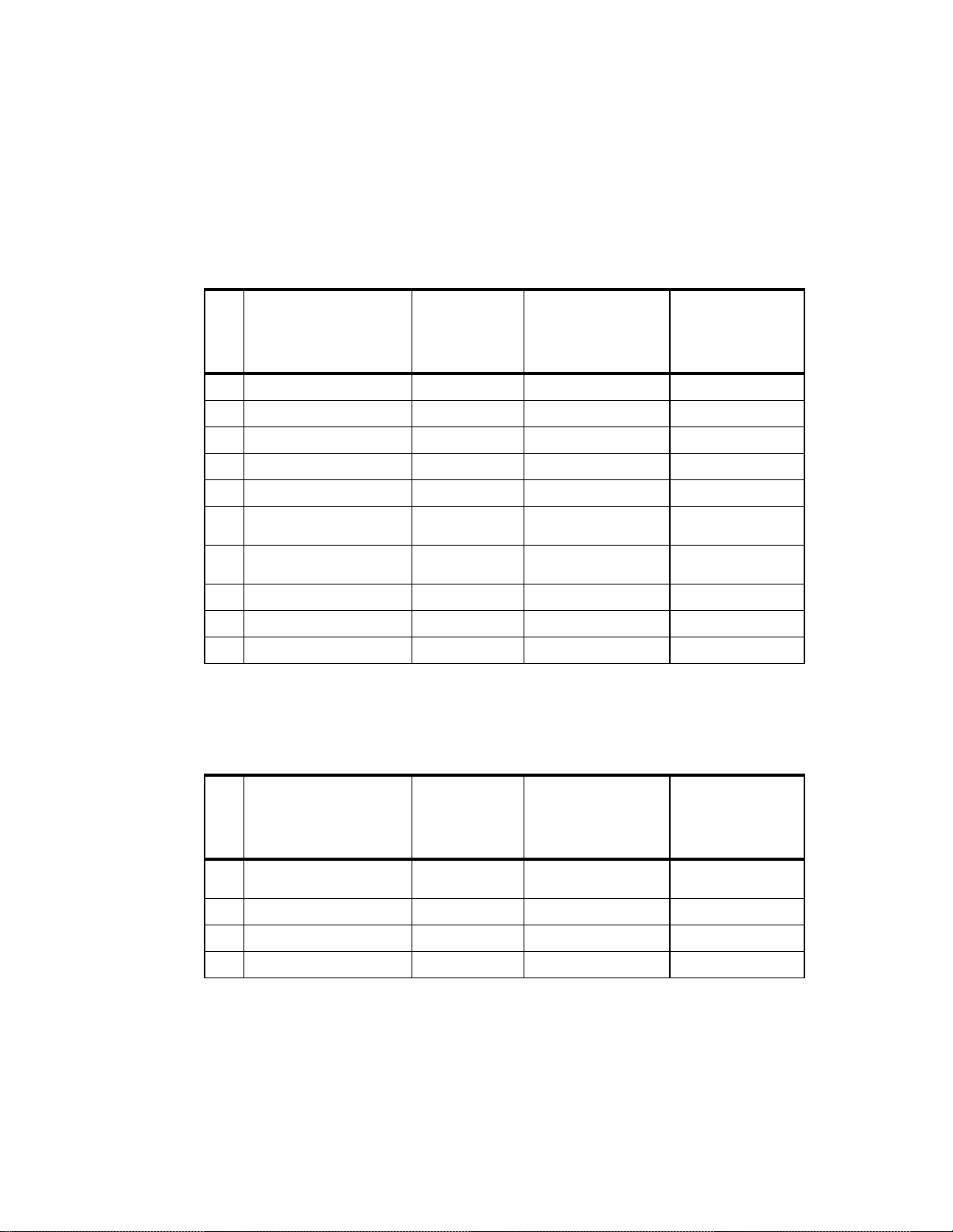
Appendix B Error Codes
Figure 5 - 0:
Table 1 - 0:
Error Codes
# Description
E0 +12V Fault. Shutdown PA. Wait til Power Level is OK.
E1 +28V Fault (PA Power Fault). Shutdown PA. Wait til Power Level is OK.
E2 +5V Fault. Save System Setup.
E3 PA Current Fault. Shutdown PA. Wait til current draw is OK.
E4 Ambient Temperature >60 C. Shutdown PA. Wait til cooled off to <55 C.
E5 PA Base Plate Temperature >80 C.Shutdown PA. Wait til cooled off to <75 C.
E6 Synthesizer not locking to (FREQ
E7 VSWR > 5:1. Shutdown PA. Check Cable & Antenna.
E8 F/W Download checksum error. Flash Message. Reload Firmware to CPU.
E9 Setup Memory checksum error. Load defaults. Will assign default values.
in MHz).
Action
Taken
Shutdown PA.
Firmware
Action for
Recovery
Recommended
Action for
Recovery
Warning Codes
# Description
W0 Ambient Temperature Rise >10 C.Flash Message.
W1 Ambient Temperature >55 C. Flash Message. Wait til cooled off to <55 C.
W2 Base Plate Temperature >75 C. Flash Message. Wait til cooled off to <75 C.
W3 VSWR > 4:1. Flash Message. Check cable and antenna.
*. Only Warning or Error Number displayed on LCD screen on the transmitter.
Action
Taken
*
Firmware
Action for
Recovery
Wait til Power Level is OK. Check for airflow block-
Recommended
Action for
Recovery
age.
Page 84

Appendix B Error Codes
B-6
Page 85
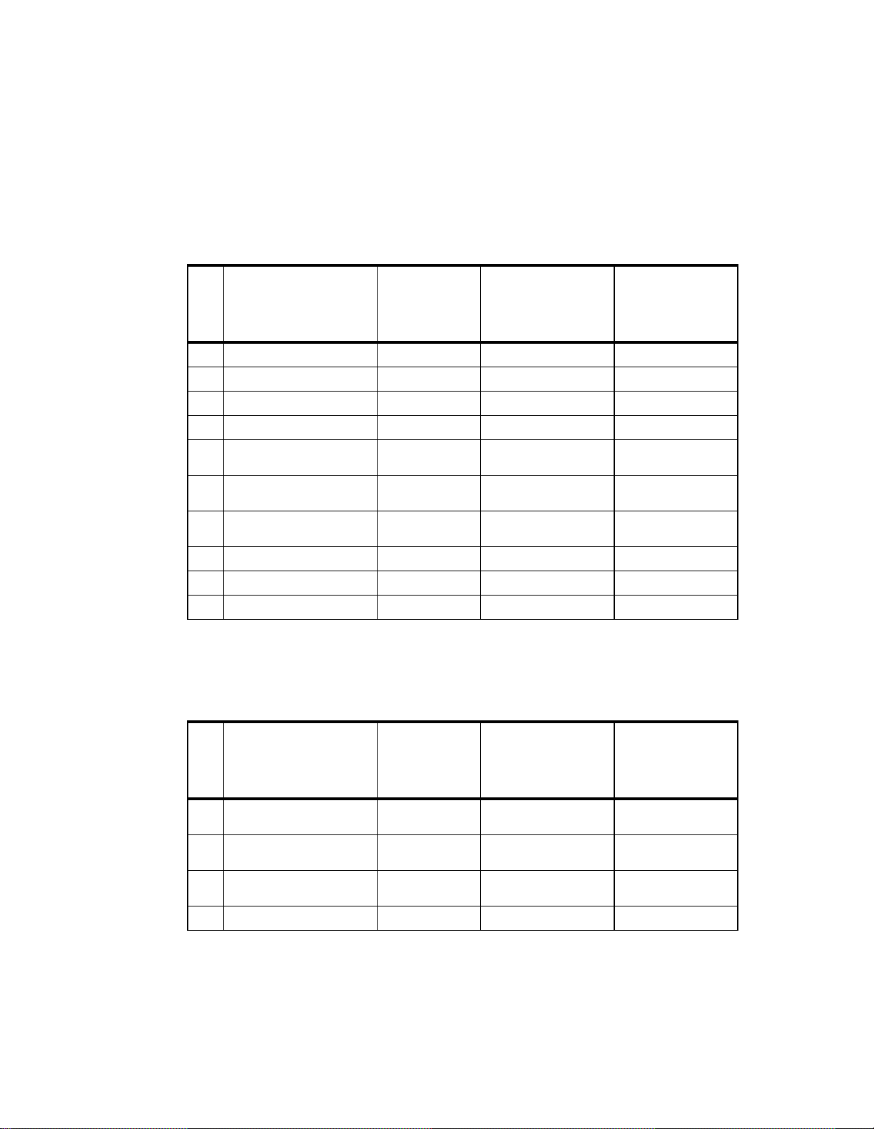
Appendix C Error Codes
Figure 9 - 0:
Table 1 - 0:
Error Codes
# Description
E0 +12V Fault. Shutdown PA. Wait til Power Level is OK. Cycle power or call LCC.
E1 +28V Fault (PA Power Fault). Shutdown PA. Wait til Power Level is OK. Cycle power or call LCC.
E2 +5V Fault. Save System Setup. Cycle power or call LCC.
E3 PA Current Fault. Shutdown PA. Wait til current draw is OK. Cycle power or call LCC.
E4 Ambient Temperature >60 C. Shutdown PA. Wait til cooled off to <55 C. Check airflow, clean air
E5 PA Base Plate Temperature >80 C.Shutdown PA. Wait til cooled off to <75 C. Check airflow, clean air
E6 Synthesizer not locking to (FREQ
E7 VSWR > 5:1. Shutdown PA. Check Cable & Antenna.
E8 F/W Download checksum error. Flash Message. Reload Firmware to CPU.
E9 Setup Memory checksum error. Load defaults. Will assign default values. Cycle power or call LCC.
in MHz).
Action
Taken
Shutdown PA. Cycle power or call LCC.
Firmware
Action for
Recovery
Recommended
Action for
Recovery
filter.
filter.
Warning Codes
# Description
W0 Ambient Temperature Rise >10 C.Flash Message.
W1 Ambient Temperature >55 C. Flash Message. Wait til cooled off to <55 C. Check for airflow
W2 Base Plate Temperature >75 C. Flash Message. Wait til cooled off to <75 C. Check for airflow
W3 VSWR > 4:1. Flash Message. Check cable and antenna.
*. Only Warning or Error Number displayed on LCD screen on the transmitter.
Action
Taken
*
Firmware
Action for
Recovery
Wait til Power Level is OK. Check for airflow
Recommended
Action for
Recovery
blockage.
blockage.
blockage.
Page 86

Appendix C Error Codes
B-8
 Loading...