

Page 1
Operator’s Manual
LBI-38690A
E
M-PA
SCAN MODEL
PORTABLE RADIO
(VGE ALGORITHM)
Page 2

TABLE OF CONTENTS
TABLE OF CONTENTS - Cont.
Page
INTRODUCTION . . . . . . 4
CONTROLS . . . . . . . . 5
ON/OFF SWITCH . . . . 5
VOLUME CONTROL
KNOB . . . . . . . . . . . 5
CONTROL KNOB . . . . 5
PTT BUTTON . . . . . . 5
MONITOR BUTTON . . . 7
EMERGENCY BUTTON . 7
MENU BUTTON . . . . . 7
PRIVATE BUTTON . . . . 8
This ma nual is published by
warranty. Improvement s and ch anges t o this ma nual necessitated by typographical errors, inaccuracies of current information, or improvements to programs and/or
equipment , may be made by
and without notice. Such changes will be incorporated
into new e ditions of this manual. No par t of this manual
may be repro duced or tran smitte d in any form or by any
means, el ectronic or mechanical, including photocopying
and record ing, for any pur pos e, wit hout the express written permission of
Ericsson Inc.
Ericsson Inc.
Ericsson Inc.
, without any
, at any time
Page
EXIT BUTTON . . . . . . . 9
SCAN BUTTON . . . . . . 9
SELECT BUTTON . . . . . 9
INDICAT ORS . . . . . . . . . 10
UNIVERSAL DEVICE
CONNECTOR . . . . . . . . 12
ALERT TONES . . . . . . . . 12
CARRIER CONTROL
TIMER . . . . . . . . . . . 12
CHANNEL BUSY . . . . . 13
RECEIVE ONLY
CHANNEL . . . . . . . . . 13
VOICE GUARD
DISABLED . . . . . . . . . 13
RADIO/CHANNEL
FAILURE . . . . . . . . . . 13
OPERATION . . . . . . . . . 13
POWER-UP . . . . . . . . 13
MODE/CHANNEL/CG
SELECTION . . . . . . . . 14
Copyright© December 1991, Ericsson GE Mobile Communications Inc.
2
Page 3

TABLE OF CONTENTS - Cont.
TABLE OF CONTENTS - Cont.
Page
CRYPTOGRAPHIC
KEYHANDLING . . . . . 15
RECEIVING A
MESSAGE . . . . . . . . 17
TRANSMITTING A
MESSAGE . . . . . . . . 18
EMERGENCY
OPERATION . . . . . . . 20
SCANNING
CHANNELS . . . . . . . 20
Using Scan . . . . . . . . 22
TELEPHONE
INTERCONNECT
CALLS . . . . . . . . . . 23
"KEYLOCK" MENU . . . 24
"ALERT" MENU . . . . . 25
OPERATING TIPS . . . . . 25
OPERATING RULES AND
REGULATIONS . . . . . . . 26
Page
REMO VING THE
BATTERY PACK . . . . . . 28
CHARGING THE
BATTERY PACKS . . . . . 28
RECHARGEABLE BATTERY
PACK DISPOSAL . . . . . 30
SWIVEL MOUNT REMOVAL AND
REPLACEMENT . . . . . . . 30
INTRINSICALLY SAFE
USAGE . . . . . . . . . . . . 30
BATTERY PACKS . . . . . 31
ACCESSORIES . . . . . . 31
GLOSSARY . . . . . . . . . 32
WARRANTY . . . . . . . . . 38
NICKEL-CADMIUM BATTERY
WARRANTY . . . . . . . . . 39
BATTERY PACKS . . . . . . 28
INSTALLING THE
BATTERY PACK . . . . . 28
3
Page 4

INTRODUCTION
This manual describes the opera-
®
tion of the M-PA Voice Guard
Scan
model radio. This full-featured portable
radio provides Voice Guard two-way
communications using the VGE algorithm. The M-PA Voice Guard radio provides full-range performance for private
(guarded) and clear communications.
The cryptographic key in the radio
provides the encryption and decryption
code n ecessar y for private communications. Only radios with the same cryptographic key can monitor and
communicate. Cryptographic keys are
transferred into the radio using VGE
Keyloader, Option V4028. VGE
equipped Vo ice Guard radios must also
be programmed with identical CUE
(Customer Unique Encryption) code(s)
before private c ommunications are possible. CUE cod es are programmed into
the radio along with the overall person-
ality information using an IBM PC or
compatible computer.
Operating controls on the radio include a r ot at able control knob, rotatable
volume control, 4-button keypad, pushto-talk, emergency and monitor buttons.
The on/off power switch for the unit is
located on the removable battery pack.
The 8-digit alphanumeric liquid
cr ystal d isplay (LCD ) on the front of the
radio displays the operating status of
the radio. This backlit display also has
twelve status flags that indicate various
operating conditions such as private
communications enabled, transmitter
on, scanning, or emergency mode enabled.
The exact operation of your radio
will vary depending upon the mode of
operation, the radio’ s programming, and
the particular radio system. Consult
your radio system’s representative for
4
Page 5

particular features that are programmed
into your radio.
CONTROLS
will decrease the audio level Minimum
levels may be programmed into the radio to prevent missed calls due to too
low of a volume setting.
ON/OFF SWITCH
The ON/OFF SWITCH is located
on the battery pack. Sliding this switch
up will supply power to the radio from
the battery pack. An audible click will be
heard and th e "ON" indi cat or will be exposed. When the radio is turned on, it
will perform a power-up self test and
then resume operation on the previous
operating channel as displayed in the
LCD. Sliding the switch down will turn
the radio off
VOLUME CONTROL KNOB
The VOLUME CONTROL K NOB is
a rotatable control on the top of the radio used to adjust the receiver’s audio
level in the speaker. Rotating this knob
in a clockw is e dir e ction will increase the
audio level. Counter-clockwise rotation
CONTROL KNOB
The rotatable 16-position CONTROL KNOB located on the top of the
radio is pr ogrammed to select the operating cha nnel, mode, or speci fic Channel Guard encode/decode tones. See
MODE/CHANNEL/CG SELECTION for
details. A stop plate may be installed
under the knob to limit the maximum
number of positions to less than sixteen
(16). It is normally factory installed for
fifteen (15) positions. Some radios may
be programmed with this knob disabled.
PTT BUTTON
Pressing the PTT BUTTON on the
side of the radio will enable the radio’s
transmitter. The "TX" status flag in the
display will turn on when the radio is
5
Page 6
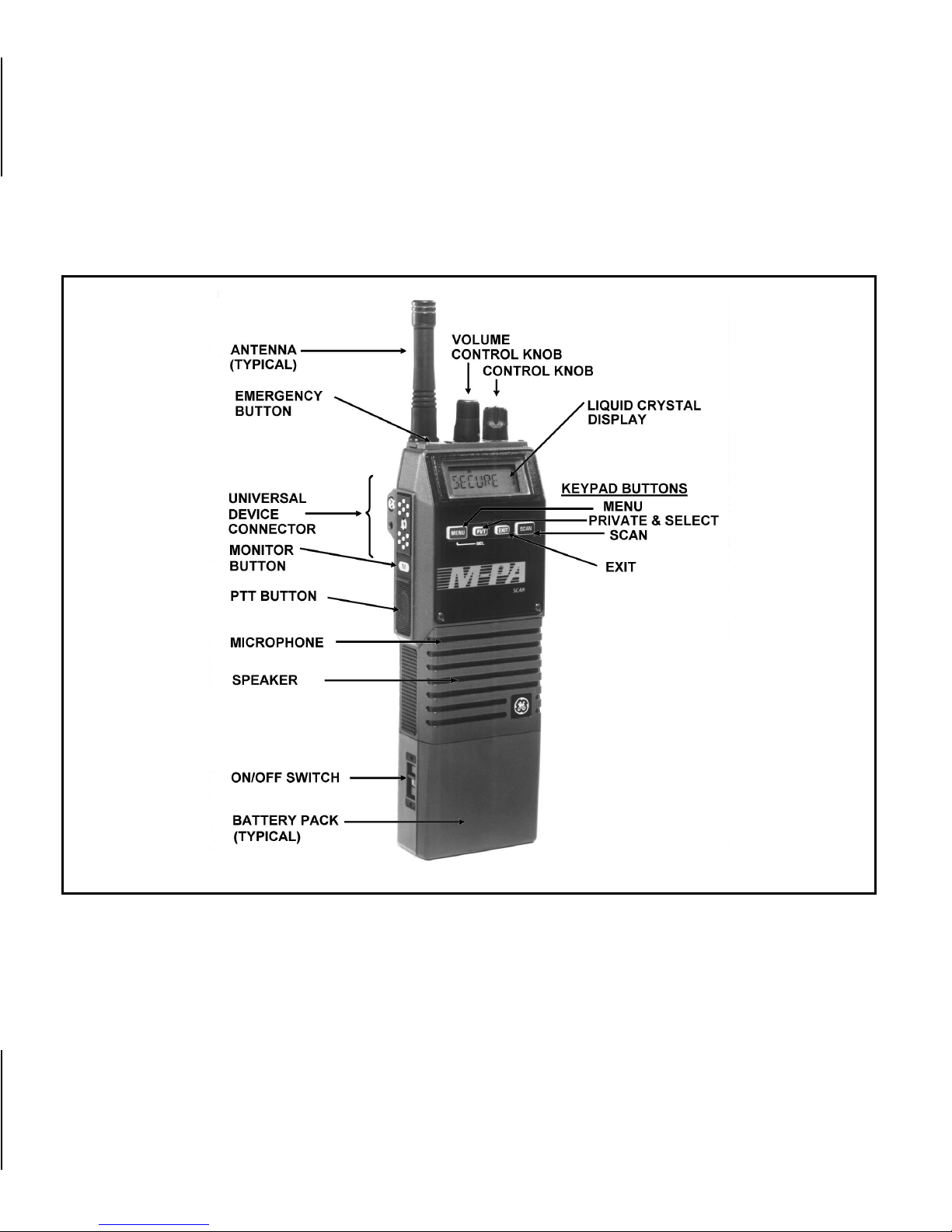
Figure 1 - M-PA Scan Model Radio
6
Page 7

transmitting. Releasing the PTT BUTTON will return operator to receive
mode.
MONITOR BUTTON
The MONITOR BUTTON is used to
unsquelch the receiver. Momentarily
pressi ng t hi s butt on will disable squelch
and the receiver noise will be heard in
the speaker.
If programmed enabled for the selected channel, Channel Guard (CG)
and/or Type 99 (T99) signaling will be
enabl ed wh en th e ch an nel i s s e l e cte d . if
CG and/or T99 are enabled, th e appropriate status flag "CG" and/or "T99" will
turn on. The MONITOR BUTTON may
then be used to toggle CG and/or T99
between disabled and enabled by
pressing and holding it for at least one
(1) second; the appropriate status flag
will toggle on or off The MONITOR
BUTTON is also used to reset T99 operation after a call is received.
EMERGENCY BUTTON
The EMERGENCY BUTTON is the
small red button located on top of the
radio near t he antenna. If this button is
programmed for emergency operation,
pressing it for at least one (1) second
will cause the radio to transmit GESTAR emer gency signaling. The "EMG"
status flag will turn on. GE-STAR is
transmit ted accordin g to one of several
different programmable methods. See
EMERGENCY OPERATION for details.
This button may also be programmed as a home mode button. if
programme d in this manner; pressing it
will switch operation to the programmed
home mode.
MENU BUTTON
Pressing the MENU button causes
the radio to scroll through up to six (6)
different menus programmed into the
7
Page 8

radio. After the desired menu is displayed, the feature within the menu is
selected with the SEL button. The
menus that may be programmed are:
Menu Display Function Or Use
"CHANNEL" The MENU and SEL
buttons are programmed
for channel selection.
When this display appears, select the desired
channel with the SEL
button and then press
EXIT.
"MODE" The MENU and SEL
buttons are programmed
for mode selection.
When this display appears, select the desired
mode by pressing the
SEL button and then
press EXIT.
"PHONE" Allows selection of one
(1) of the ten (10) programmed telephone
numbers for automatic
dialing.
"KEYLOCK" Allows the keypad but-
tons to be locked or unlocked.
"SCAN A/D" Allows channels to be
added to or deleted from
the scan list for the current mode. The priorityone channel and the
priority-two channel are
also set within this
menu.
"ALERT" Allows the alert tones to
be disabled or enabled.
PRIVATE BUTTON
Private transmit mode is enabled or
disabled by pressing and releasing the
8
Page 9

PVT button (when the menu mode is
not selected). When private transmit
mode is en abled, the "PVT" status flag
in the display will turn on.
If the radio is programmed for
forced private operation and the selected channel is programmed for private operation, "FRCD PVT" will be
displayed when PVT is pre ssed; private
transmit mode is not disabled. If the radio is programmed for forced private operation a nd the se lected channel is not
programmed for private operation, "VG
DISBL" will momentarily show in the
display when PV T is pressed; the radio
will not change to private mode.
EXIT BUTTON
Pressing the EXIT button will cause
the radio to exit the current menu display and return operation to the channel
curren tly selecte d. If the menu mode is
not enab led when the button is pressed,
pressi ng thi s button will tur n the display
and keypad backlighting on for thirty
(30) seconds (if the backlight is programmed on).
SCAN BUTTON
Pressing the SCAN button on the
keypad will toggle scan operation on
and off. When the radio is scanning, the
"SCN" status flag in the display will
show and all channels on the scan list
will be scanned. See SCANNING
CHANNELS for additional details.
Figure 2 - MPA Scan Model Keypad
SELECT BUTTON
Selecting different features within
each menu is accomplished with the
SEL button . First, the menu mode must
9
Page 10
be enabled an d the desire d menu must
be chosen by pressing and releasing
the MENU button until the desired
menu appears in the display After the
menu is ch os e n, th e d es i red fu nc t io n or
feature is se lected by pr essing the SEL
button. For example, to disable or enable the aler t tones, press MENU until
"ALERT" is displayed then press SEL to
select "ENABLED"or "DISABLED", as
desired. Next press the EXIT button.
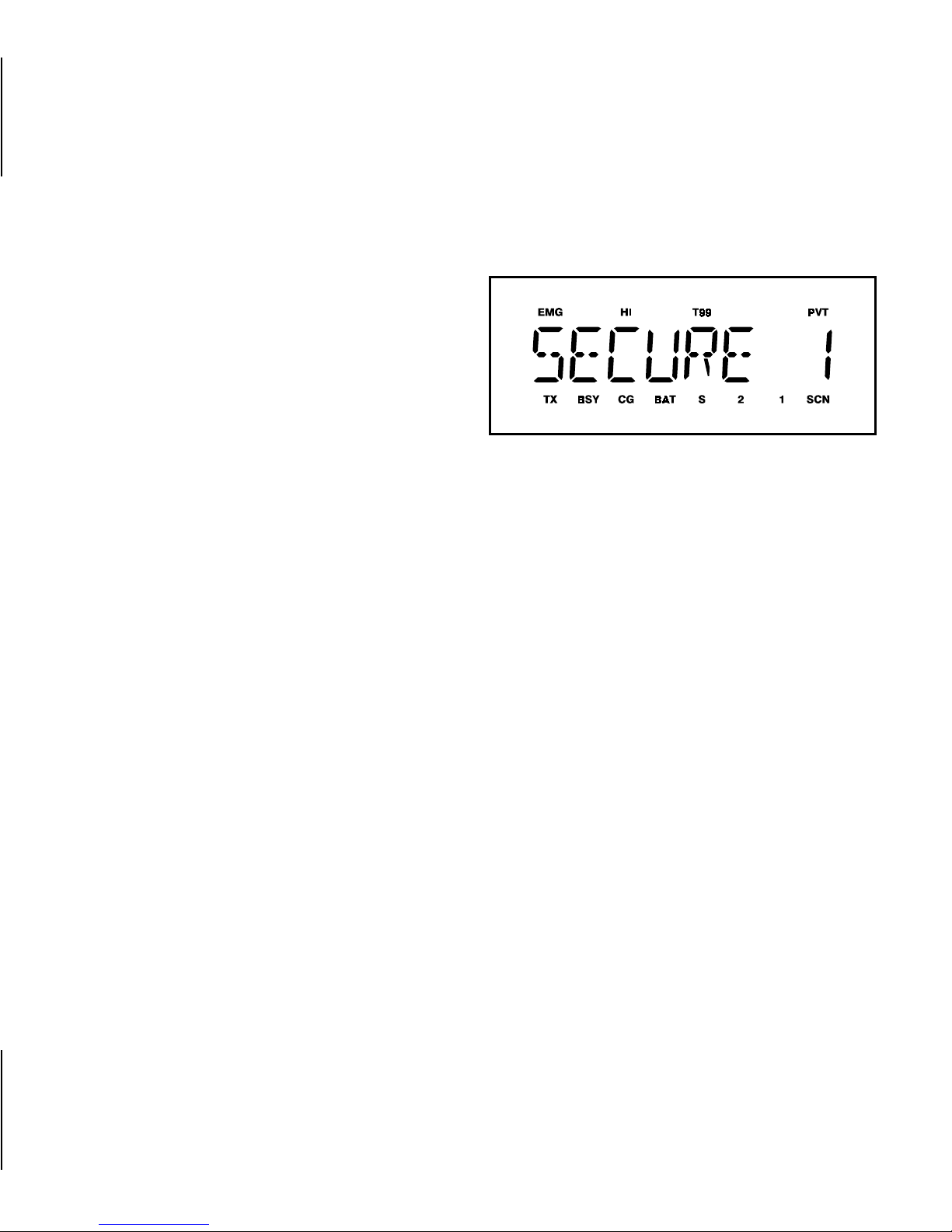
INDICATORS
The radio’s liquid crystal display
(LCD) located on the front panel has
eight (8) alphanumeric characters and
twelve (12) status flags. This display indicates the current operating channel
and it displays the menu information
when this mode is enabled. It also displays v arious other messages.
LCD backlighting will turn on for a
short period any time an acti ve button is
pressed or the CONTROL KNOB is ro-
Figure 3 - Liquid Crystal Display
tated. Backlighting may be programmed
to remain off at all times. Pressing the
EXIT button when the menu mode is
not enabled, will turn display and keypad backlighting on for thirty (30) seconds (if backlight programming is on).
The twelve (12) s t at us f lags located
along the top and bottom of the display
indicate operating status as follows:
EMG EMerGency mode - On indi-
cates emergency GE-STAR signaling has been initiated by the
user.
HI HIgh power transmit - On indi-
cates the selected channel has
10
Page 11

been programmed for high
power transmit operation. Off indicates low power transmit.
T99 Type 99 tone decode-On indi-
cates Type 99 tone decoding is
enabled on the selected channel. Flashing indicates a T99 selective call has been received
and the radio must be reset to
receive another T99 call.
PVT PriVaTe mode - On indi c a t e s pri -
vate mode is enabled and the
radio will transmit encrypted
messages on the selected channel. Flashing indicates an encrypted message is being
received.
TX Transmitter enabled - On when
the radio is transmitting.
BSY BuSY - On indicates a carrier is
being received (the channel is
busy). Note that if the selected
channels programmed for Channel Guard ( CG), D igital Channel
Guard (DCG), or Type 99 (T99)
tone decode operation, the radio
may not unsquelch if a valid
tone(s) is not received; the BSY
status flag will be on.
CG Channel Guard - On indicates
tone Channel Guard (CG) or
Digital Channel Guard (DCG)
encode/decode is enabled on
the selected channel.
BAT BATtery low - On indicates the
battery pack’s charge is low.
S Scan list - On indicates the se-
lected channel is on the scan
list.
1 priority 1 - On indicates the se-
lected channel is designated as
the priority-one scan channel.
11
Page 12

2 priority 2 - On indicates the se-
lected channel is designated as
the priority-two scan channel.
SCN SCaN mode - On indicates the
radio is scanning.
UNIVERSAL DEVICE CONNECTOR
The Universal Device Connector
(UDC) is located on the sid e of the radio just above the PTT and MONITOR
BUTTONS. This connector provides
connections for the external accessories such as a headset, a speak er-m ik e ,
or an e merge ncy la nyard. When the radio is locked in a vehicular charger/repeater, the UDC provides the audio and
control connections between the radio
and the vehicul ar c harge r/r epe ater. The
UDC is also used by the maintenance
personnel when the radio is programmed.
ALERT T ONES
The M-PA uses alert tones or
"beeps" to indicate various operating
conditions. Alert tones may be enabled
or disabled via the menu mode if the
"ALERT" feature is programmed. See
"ALERT" MENU for details. The alert
tones may be disabled when the radio
is programmed.
CARRIER CONTROL TIMER
This feature, programmable on a
per channel basis, prevents unnecessary channel traffic and radio damage
in the event of a "stuck" mic. If the programmed timer times-out during a
transmission, the radio will sound an
aler t tone and disable the transmission.
The beepin g tone will continue until the
PTT BUTTON is released. Releasing
the PTT BUTTON resets the timer.
12
Page 13

CHANNEL BUSY
If the radio is receiving a signal
when the PTT BUTTON is pressed, an
alert tone will warn the operator that the
radio is receiving a carrier and the
transmission will not occur. "RX BUSY"
is displayed and the alarm is sounded
as long as the PTT BUTTON is
pressed. This feature is programmable
on or off on a per channel basis.
RECEIVE ONLY CHANNEL
If the selected channel is programmed as receive only, the radio will
sound a n alert tone if a transmission is
attempted. "RX ONLY" is displayed.
VOICE GUARD DISABLED
If the selected channel is programmed for private operation and private transmit mode has been disabled
using the PVT button, the radio will
sound a low-pitched beep when the
PTT button is pressed. This warns the
operator of the clear mode transmission.
RADIO/CHANNEL FAILURE
If the synthesizer is unable to lock
correctly on the selected channel, or
another radio failure occurs, an alert
tone will sound. If incorrect programming is dete cted or the synthesizer fails
to lock, the display flashes "NO LOCK"
then the selected channel’s name.
OPERATION
POWER-UP
After th e battery pack and antenna
have been installed, turn the radio on
by sliding the ON/OFF SWITCH on the
battery pack up. After the radio has
complete d power-up self-tes t, it wil l begin operation on the last operating state
as displayed in the LCD. If programmed
on, the power-up alert tone (beep) will
be heard.
13
Page 14

MODE/CHANNEL/CG SELECTION
The M-PA Scan model radio may
be program med with up to 176 different
radio channels. A maximum of 11
modes of 16 channels each or 16
modes of 11 channels each may be
programmed into the radio (11 x
16=176). Select the desired mode
(bank of channels) and channel, or
channel and Channel Guard (CG), according to the radio’s programming as
follows:
3. Press the EXIT button to switch
radio operation to the selected
mode and exit the menu.
4. Select the desired channel by
rotating the CONTROL KNOB
until the de s ire d c ha nn el ’s name
appears in the display.
CONTROL KNOB Selects Mode
MENU And SEL Selects Channel
(And CG)
MENU And SEL Selects Mode
CONTROL KNOB Selects Channel
(And CG)
1. Press the MENU button until
"MODE" appears in the display.
2. Press the SEL button to select
the desired mode. The selected
mode’s name will appear in the
display.
14
1. Select the correct mode by ro-
tating the CONTROL KNOB until the desired mode’s name
appears in the display.
2. Press the MENU button until
"CHANNEL" appears in the display.
3. Press the SEL button until the
desired channel’s name appears
in the display.
Page 15

4. Press the EXIT button to switch
radio operation to the displayed
channel and exit the menu.
MENU and SEL Select Mode. And
Channels CONTROL KNO B Select.
Channel Guard
1. Press the MENU button until
"MODE" appears in the display.
2. Press the SEL button until the
desired mode’s name appears
in the display.
6. Select the desired Channel
Guard using the CONTROL
KNOB. The "CG" stat us flag will
turn on if the selected position
has CG programmed. Position
fifteen (15) is a non-CG position;
it may not be programmed with
a Channel Guard. Position sixteen (16) is a default channel
CG position; selecting it will
switch CG to the CG programmed for the selected channel.
CRYPTOGRAPHIC KEYHANDLING
3. Press the MENU button until
"CHANNEL" appears in the display.
4. Press the SEL button until the
desired channel’s name appears
in the display.
5. Press the EXIT button to switch
radio operation to the new mode
and channel, and exit the menu.
Cryptographic keys are transferred
into the radio using the Keyloader, Option V4028. Refer to the Keyloader operator’s manual (LBI-31685) for detailed
instructions on ho w to lo ad k e ys i nt o t he
Ke yloader .
The radio is capable of storing up to
seven (7) different cryptographic keys in
15
Page 16

its memory. It is programmed for key selection on a channel or per mode basis.
NOTE
4. Press the PWR button on the
Keyloader and waft for the Keyloader to display "MASTER
MODE".
Before private messages can be sent
or received, one or more cryptographic keys must be transferred into
the radio from the Keyloader.
Transferring Keys Into The Radio
The following procedure outlines
basic key transferring steps. See LBI31685 for more details.
1. Turn the radio off.
2. Plug the modular connector of
the Keyloader cable into the
Ke yloader’s modular jack.
3. Connect the Keyloader cable to
the UDC on the radio .
5. Press the TRN button on the
Keyloader. If neces sary, s elect a
different cryptographic key to be
transferred into the radio.
6. Turn the radio on. The display
should read "KEY LOAD".
7. Press the EXE button on the
Keyloader to transfer the key
The Keyloader will display
"GOOD 1.x TRANSFER" where
“x” is the selec ted cr yptographic
key number.
8. Disconnect the cable from the
radio’s UDC. A single beep will
be heard from the radio’s
speaker if the power-up alert
tone is enabled. The radio will
16
Page 17

change to the selected channel
last indicated in the display.
and beep if the power-up alert
tone is programmed on.
Key Zero
All cryptographic keys stored in the
radio can be zeroed or "dumped" when
the radio i s on by s imultaneous ly press ing the ME NU and S CAN buttons for at
least one second. When the key(s)
have been zeroed, the radio will display
"KEY ZERO" and it will emit a series of
beeps. CUE codes stored in the radio
are not affected. If the cryptographic
key(s) are zeroed, one or more keys
must be transferred into the radio from
the Keyloader before private communications may continue.
RECEIVING A MESSAGE
1. Slide the ON/OFF SWITCH on
the batter y pack to the on position. The radio will initiate and
complete the power-up self-test
2. Select the desired operating
mode, channel, and/or Channel
Guard. See the MODE/ CHAN-
NEL/ CG SELECTION for details.
3. Press the MONITOR BUTTON
to disable squelch and adjust
the VOLUME CONTROL for the
approximate desired speaker
audio level. Pressing the MONITOR BUTTON may affect Channel Guard and/or Type 99 tone
operation if programmed for the
selected channel.
4. If the selected channel is programmed for private operation,
the radio will automatically
switch between clear or private
receive operation.
17
Page 18

When an encrypted transmission is received, the "PVT"
status flag will flash, the receiver
will unsquelch, and the Voice
Guard mess age will be heard in
the speaker. For this to occur,
the selected channel must be
programmed for private operation, the correct cryptographic
key must be loaded into the radio and the correct CUE code
must be programmed.
TRANSMITTING A MESSAGE
1. Select the desired mode, chan-
nel, and/or Channel Guard.
2. When private mode is enabled,
the "PV T" status flag in the display will turn on. Toggle transmit
operation to private or clear, as
desired, by pressing the PVT
button (when the menu mode is
not enabled).
If a clear mode (non-encrypted)
transmission is received, the receiver will unsquelch and it will
be heard in the speaker. However, if the selected channel is
programme d for Channel Guard
or Type 99 tone operation, the
receiver will not unsquelch unless the c orrect CG or T99 tone
is received.
5. Adjust the volume as necessary.
18
If a channel is not programmed
for private mode operation, "VG
DISBL" will momentarily show in
the displ ay if an attempt is made
to enable private transmit mode.
It is not possible to operate on
this channel in private mode.
If the radio is programmed for
forced private ope ration, "FRCD
PVT" will momentarily show in
the display. If an attempt is
made to d isable private transmit
Page 19

mode. It is not possible to transmit on this channel in clear
mode.
If a chann el pr ogrammed for private operation is selected and
there is no key in the radio for
the selected channel "NO KEY
x" (where "x" is the key number)
will periodically flash in the display. If a transmission is attempted, "NO KEY x" will show
in the display and the radio will
emit a series of beeps and will
not transmit.
3. Ensure no one is transmitting on
the selected channel by pressing the MONITOR BUTTON to
disable squ elch or observing the
display for the absence of the
"BSY" status flag. If the Channel
Busy Lockout feature is programmed for the selected channel, the radio will not transmit
when the channel is busy.
4. Press and hold the PTT BUTTON. If the selected channel is
programmed for private operation and clear transmit mode
has been selected, an alert tone
(low pitch ed beep) will be heard
in the speaker when the PTT
BUTTON is pressed as a warning that radio is not in private
mode. The "TX" and "BSY"
status flags are displayed.
5. Hold the radio approximately
three inches from your mouth
and speak into the microphone
in a normal voice.
6. Release the PTT BUTTON
when the transmission is complete. If the transmission exceeds the programmed Carrier
Contro l Tim er limit, the radio will
unkey and an alert tone will
sound.
7. Listen for a reply.
19
Page 20

EMERGENCY OPERATION
The radio may be programmed to
transmit GE-STAR emerge ncy signa li ng
when the EMERGENCY BUTTON is
pressed or from a UDC connected lanyard. If the EMERGENCY BUTTON is
programmed for GE-STAR emergency
activation, press for approximately one
(1) sec ond to ac tivate the transmission.
If the lanyard is p rogramme d for activation, follow the instructions provided
with it. GE-STAR is programmed to
transmit in one of the following methods:
•• GE-STAR is transmitted on
predetermined mode and channel
regardless of the selected channel. In
this case the selected channel is
available for voice and the radio will
periodically "jump" to the
predetermined channel and send the
emergency message and then "jump
back" to the selected channel for
voice operation.
•• GE-STAR is transmitted on the
selected channel. If the channel is
changed, the emergency bursts will
follow the newly selected channel.
•• Th e radio switches to and stays on a
predetermined mode and channel
and GE-STAR is transmitted on that
channel. Rotating the CONTROL
KNOB will not change channels.
Turning the radio off and back on will
reset this condition.
•• GE-STAR is sent on the selected
channel an d the radio l ocks onto that
channel. Rotating the CONTROL
KNOB will not change channels.
Turning the radio off and then back
on will reset this condition.
SCANNING CHANNELS
The M-PA m ay be programm ed for
non-priority scan, dual-priority scan, or
scan operation may be disabled. Scan
programming options include a keypad
entered scan list or a fixed scan list. Pri-
20
Page 21

ority scan programming options include
a fixed priority-one channel or the selected channel as the priority-one channel.
The radio may be programmed to
scan only the channels in the current
mode or it may be programmed to scan
across modes.
Scan rate will var y depending upon
the number of channels on the scan list
and whether or not the radio is programmed to scan for Channel Guard.
Fewer channels will result in a faster
scan rate. All scan functions are retained in memory when the battery
pack is removed.
The radio will not scan when the
emergency mode is enabled ("EMG"
status flag is on).
Adding Channels To And Deleting
Channels From The Scan List
If the "SCAN A/D" menu is programmed, channels may be added to
and deleted from the scan list of each
mode as follows:
1. Select the desired mode and
channe l. If the selected channel
is currently on the list, the "S"
status flag will be on.
2. Press the MENU button until
"SCAN A/D" is displayed.
3. Press the SEL button until the
desired priority indicator appears: "S" for non-priority "2" for
priority-two, "1" for a priorityone, or no indicator to remove
the channel from the scan list. If
a new priority channel is selected, the previous corresponding priority channel will become
a non-priority scan channel. One
21
Page 22

of the following messages may
be momentarily displayed:
•• “SCAN DIS”- - The radio is not
programmed to scan.
Using Scan
Toggle scan on or off by pressing
SCAN. The "SCN" status flag turns on
when the radio is scanning.
•• “F IXED P1"- - A priority-one channel
has been p rogrammed into the radio.
A new prior ity-one channel c annot be
selected.
•• "FIXD LST" - - A fixed scan list is
programmed into the radio. It is not
possible to change the list without
reprogramming the radio.
4. To add or delete additional
channels, repeat steps 2
through 4.
5. Press the EXIT button to return
to normal operation.
If programmed for dual-priority scan
operation, the priority-one, priority-two
and the remaining channels will be
scanned. Once a carrier is detected
and, if programmed, the correct Channel Guard is decoded, the display will
indicate the channel. Sampling of the
priority-one and priority-two channels
will continue. Should a priority-one or
two channel carrier, regardless of
Channel Guard, be detected while a
non-priority channel is being received,
the disp lay name is updated, the applicable status indicator, "1" or "2" lights,
and the channel is switched to the priority cha nn el . Sampling of the pr iority -one
channel will continue if a message is
being received on the priority-two channel.
22
Page 23

If progra mmed for non- prior ity scan
operation, once a carrier is detected,
and if programmed, the correct Channel
Guard is decoded, the display will indicate the detected channel. Scanning
will stop and the radio will remain on the
channel until the carrier ceases. Scanning will then resume with the selected
channel’s name displayed.
TELEPHONE INTERCONNECT
CALLS
Telephone interconnect calls may
be placed on radio channels equipped
with this capability. Each channel programmed into the radio may be programmed for tele phone interconnect by
enabling it f or DTMF dial operation. One
(1) of ten (10) programmed telephone
numbers can be s elect ed and a utomatically dialed. Voice transmissions may
be encrypted if the channel is programmed for private operation and the
operator selects private mo de after the
dial sequence is completed.
Communication takes place in a
simplex mode. In other words, the PTT
BUTTON must be pressed each time
you wish to t ransmit and it must be released to receive.
Placing A Call
Ten (10) te lephone numbers can be
programmed in the radio for automatic
dial operation. Typically, telephone numbers programmed into the radio by the
maintenance personal each have a
specific name (8 characters maximum)
assigned. For example: “OFFICE” or
“HOME”. To recall a number and complete a call. proceed as follows:
1. If the "SCN" status flag is on,
press SCAN to turn scan off.
2. Select a channel in your radio
system that has telephone interconnect capability The radio
should be programmed for
23
Page 24

DTMF operation on this channel.
sired, enable private mode by
pressing the PVT button.
3. If private mode is enabled
("PVT" status flag on), press the
PVT button to disable private
mode.
4. Press the MENU button until
"PHONE" appears in the display.
5. Press the SEL button to scroll
through the phone list until the
programmed name for the desired telephone number appears
in the display.
6. Press and release the PTT
BUTTON to automatically dial
the selected number.
7. Wh en the called par ty answers,
press the PTT BUTTON to
transmit and release it to receive. Repeat as needed. If de-
8. At the completion of the call,
press the EXIT button. The radio
will then transmit the disc onnect
digit to hang-up.
"KEYLOCK"MENU
The "KEY LOCK" menu allows the
keypad to be l ocked or disabled to prevent accidental activation. If this menu
is programmed into the radio, lock and
unlock the keypad as follows:
Lock The K eypad
1. If the "SCN" status flag is on,
press SCAN to turn scan off.
2. Press the Menu button until
"KEYLOCK" appears in the display.
3. Press the SEL button until
"LOCKED" is displayed.
24
Page 25

4. To lock the keypad press the
EXIT button.
2. Press the MENU button until
"ALERT"appears in the display.
Unlock The Ke ypad
1. Press the MENU BUTTON until
"KEYLOCK" appears in the display.
2. Press the SEL button until "UNLOCKED" is displayed.
3. To unlock the keypad press the
EXIT button.
"ALERT" MENU
The "ALE RT" me nu al lows t he alert
tones to be disabled or enabled. If this
menu is programmed into the radio, disable and enable the alert tones as follows:
Disable The Alert T ones
1. If the "SCN" status flag is on,
press SCAN to turn scan off.
3. Press the SEL button until "DISABLED" is displayed.
4. To disable the tones press the
EXIT button.
Enable The Alert T ones
1. Press the MENU button until
"ALERT" appears in the display.
2. Pre ss the SEL button until "ENABLED" is displayed.
3. To enable the tones press the
EXIT button.
OPERA TING TIPS
Antenna location and condition is
important when operating a portable radio. O perating the radio in low areas of
terrain, under power lines or bridges, inside of a vehicle or in a metal or steel
25
Page 26

framed building can severely reduce the
range of the unit. Mountains and buildings can also reduce the range of the
unit.
In areas where transmission or reception is poor , some improvement may
be obtained by insuring that the antenna is vertical. Moving a few yards in
another direction or movin g to a higher
elevation may also improve communication. Vehicular operation can be aided
with the use of an externally mounted
antenna.
Battery condition is another important factor in the trouble free operation
of a portable radio. Always properly
charge the batteries.
Always observe all of the Federal
Communication Commission’s rules
and regulations.
OPERATING RULES AND
REGULATIONS
Two-way FM radio systems must be
operated in accordance with the rules
and regul ations of t he Federal Communication s Commission (FCC ). As an operator of two -way radio equipment, you
must be thoroughly familiar with the
rules that apply to your particular type
of radio operation. Following these rules
will help eliminate confus ion, assur e the
most efficient use of the existing radio
channels, and result in a smoothly func tioning radio network.
When using your two-way radio, remember these rules:
1. It is a violation of FCC rules to
interrupt any distress or emergency message. As your radio
operates in muc h the same way
as a telephone "party line", always listen to make sure that
the channel is clear and/or ob-
26
Page 27

serve the display for the absence of the "BSY" status flag
before transmitting. Emergency
calls have priority over all other
messages. If someone is sending an emergency message such as reporting a fire or asking for help in an accident KEEP OFF THE AIR!
2. The use of profane or obscene
language is prohibited by Federal law.
emergency) is a violation of
FCC rules. You may send only
those messages that are essential for the operation of your
business.
6. It is against Federal law to repeat or otherwise make known
anything you overhear on your
radio. Conversations between
others sharing your channel
must be regarded as confidential.
3. It is against the law to send false
call letters, or false distress or
emergency messages.
4. The FCC requires that you keep
conversations brief and confine
them to business. To save time,
use code d messages whenever
poss ible.
5. Using your radio to send personal messages (except in an
7. The FC C re qu ir e s th at you identify yourself at certain specific
times by means of your call letters. Refer to the rules that apply
to your par ticular type of operation for the proper procedure.
8. No changes or adjustments
shall be m ade to the equipm ent
except by an authorized or certified electronic technician.
27
Page 28

BATTERY PACKS
INSTALLING THE BATTER Y PA CK
1. Ensure the ON/OFF SWITCH
on battery pack is in the off position.
2. Hol d the radio and batter y pack
with the back of them facing
you.
3. Align the batter y pack and radio
slide grooves. See Figure 4.
4. Slide the battery pack fully into
the radio until the battery release latch clicks into place.
REMO VING THE BATTER Y PA CK
1. Ensure the ON/OFF SWITCH
on the battery pack is in the off
position.
2. Press down on the battery release lat ch and sli de the battery
28
Figure 4 - Installing Battery Packs
pack out in the direction of the
release latch. See Figure 5.
CHARGING THE BATTER Y PA CKS
After receiving a new rechargeable
batter y pack from the factory, it should
be fully charged before placing it into
service. This also applies to recharge-
Page 29

able batte ries that have been stored for
long per iods. When the battery pack requires charging t he radio will signal the
operator with an alert tone and the
“BAT” status flag will turn on.
Chargers are av ailable with nominal
charge times of 1 hour (rapid) and 14
hours (s tandard). Combinations include
single ( 1) and multi ( 5) position, s tandard and rapid charge units. In addition,
the vehicular chargers/repeaters simultaneously charge the battery packs
while the radio is operating. For specific
instructions refer to the applicable
charger Operating Manual.
Figure 5 - Removing Battery Pack
The rechargeable batteries used
with the radio can develop a reduced
capacity conditi on someti mes cal le d th e
“Memor y Effect”. This condition can occur when a battery is continuously
charged for long periods or when a
regularly performed duty cycle allows
the battery to expend only a limited portion of its capacity. The battery pack
may show a severe decrease in its ability to deliver full capacity for an extended period. Any rechargeable
battery pack showing signs of reduced
capacit y should be retu rned to a qualified service center for inspection.
29
Page 30

RECHARGEABLE BATTERY PACK
DISPOSAL
The product that you have
purchased contains a rechargeable, recyclable battery. At the end of its useful
life, under various state and
local laws, it may be illegal to dispose of
this battery into the municipal waste
stream. Check with your local solid
waste officials for details in your area
for recycling options or proper disposal.
Call Toll Free 1-800-8-BATTERY for information and/or procedures for returning rechargeable batteries in your state.
SWIVEL MOUNT REMOVAL AND
REPLACEMENT
Figure 6 - Removal And Replacement
Of Swivel Mount
To replace the swivel mount, place
the end of the swivel in the grooves in
the radio a nd slide the mount up until it
snaps in place.
To remove the swivel mount, slide a
flat blade screwdriver underneath the
spring ret ainer and twis t. While twisting,
slide the swivel mount out from under
the holder.
30
INTRINSICALLY SAFE USAGE
Selected portable radios with appropriate factory installed F4 Options
are certified as Intrinsically Safe by the
Factory Mutual Research Corporation.
Intrinsically Safe approval includes
Page 31

Class I, II, III, Division 1 hazardous locations in the presence of groups C, D,
E, F and G at mospheres. Non-Incentive
approval includes Class I, Division 2
hazardous locations in the presence of
Groups A, B, C and D atmospheres.
Hazardous locations are defined in
the National Electrical Code. Useful
standar ds NFPA 4 37A and NFPA 437M
for the classifications of hazardous areas can be ordered from the National
Fire Protection Association, Batterymarch Park, Quincy, MA 02269.
PA PA 1 F R e c h a r ge ab l e B a t t e ry P a c k ,
Extra High Capacity
(Tall Case)
PA PA 1 G R e c ha rge ab l e B a t t e ry P a c k ,
High Capacity
(Short Case)
ACCESSORIES
The acces sories th at follow are approved for use with intrinsically safe radios. Use of accessories other than
those listed voids Factory Mutual approval.
BATTERY PACKS
Only battery packs identified with a
green latch shall be used with a portable radio that is rated and labeled as
Factory Mutual Intrinsically Safe. Use of
nonspecified battery packs voids Factor y Mut ual ap proval. The following batter y pack options are approved for use
in intrinsically safe radios.
PAAB1A Headset/Microphone
PAAC1J EarpieceKit
PAAC1B GE-STAR Lanyard
PAAE3R Speaker/Microphone
PAAE1B Speaker/Microphone with
GE-STAR Lanyard
PAAE3T Speaker/Microphone/
Antenna
PANC1B Antenna, 136-151 MHz,
Helical
31
Page 32

PANC1F Antenna, 440-470 MHz,
Helical
PANC1L Antenna, 378-440 MHz,
Whip
PANC1N Antenna, 440-512 MHz,
Whip
GLOSSARY
clear mode- communicating in a
non-encrypted format (non-scrambled)
PANC1H Antenna, 806-870 MHz,
Elevated Feed
PANC1K Antenna, 806-870 MHz,
Flex
PANC1U Antenna, 378-440 MHz,
Helical
PANC1Z Antenna, 896-941 MHz,
Whip
PAHC1C Belt Clip
PAHC1D Swivel Mount with Belt Loop
PAHC3W Case, Leather, with Belt
Loop (Short Case)
PAHC1K Shoulder Strap, Leather,
with Mounting Plate
PAHC5R Holster, Plastic
cryptographic key- the numb er or code
used by the encryption and decryption
circuitry to encode
and decode a signal
CCT- Carrier Controlled
Timer - a programmable timer that will
disable a transmission if the timer
length is exceeded
CG- Channel Guard - a
method of controlling squelch with a
tone or digital code
(Channel Guard is
GE’s trade name for
coded squelch)
32
Page 33

CUE- Customer Unique
Encryption - a code
programmed into
the personality of
the radio that modifies the cryptographic key to
provide an additional layer of voice
security
decryption- the process of de-
coding or descrambling a signal
according to a predetermined algorithm
encryption- the process of en-
coding or scrambling a signal
according to a predetermined algorithm
private mode- communicating in
an encrypted format
(scrambled)
T99- Type 99 - a method
of opening squelch
for selective page
operatio ns usin g sequential tones
VGE- a proprietary en-
cryption/decryption
algorithm used to
scramble or descramble a signal
RADIO TYPE_______________________________________________________
FREQUENCY BAND_________________________________________________
OPERATOR’S NAME________________________________________________
33
Page 34

MODE
NUMBER
MODE
NAME
CHANNEL
NUMBER
CHANNEL
NAME
VG CG/
T99
USE
34
Page 35

MODE
NUMBER
MODE
NAME
CHANNEL
NUMBER
CHANNEL
NAME
VG CG/
T99
USE
35
Page 36

MODE
NUMBER
MODE
NAME
CHANNEL
NUMBER
CHANNEL
NAME
VG CG/
T99
USE
36
Page 37

PRODUCT SPECIFICATION FOR CE
MARKED EQUIPMENT
The M-PA Portable conforms to the
following Product Specifications.
EUROPEAN STANDARDS:
SUPPLEMENTARY INFORMATION:
At this time, the M-PA por table radio
may not be o perated while in a vehicular
charger in the European Community
since it has not been evaluated for operation in this mode.
Safety: Not Applicable
EMC: prETS 300 279
(August 1995)
TTD: Not Applicable
The M-PA portable radio may be
used in both trunked and conventional
applications.
37
Page 38

WARRANTY
A. Ericsson Inc. (hereinafter "Seller") warrants to the original purchaser for use (hereinafter "Buyer") that Equipment manufactured by Seller
shall be free from defects in material, workmanship and title, and shall conform to its published specifications. With respect to a n y E qu ipment not manufactured by Seller (except for integral parts of Seller’s Equipment to which the warranties set forth above shall apply).
Seller gives no warranty, and only the warr anty, if any, given by the ma n ufacturer shall apply. Batteries are excluded from this warranty but
are warranted under a separate Nickel-Cadmium Battery Warranty .
B. Seller’s obligations set forth in Paragraph C below shall apply only to failures to meet the above warranties (except as to title) occurring
within the following periods of time from date of sale to the Buyer and are conditioned on Buyer’s giving written notice to Seller within
thirty (30) days of such occurr en ce:
1. for fuses, incandescent lamps, vacuum tubes and non-rechargeable batteries, operable on arrival only .
2. for parts and accessories (e xcep t as no te d in B .1 ) sold b y Se ller’s Service Parts Operat ion , nin et y (90) days.
3. for all other Equipment of Seller’s manufacture, one (1) year.
C. If any Equipment fails to meet the foregoing warranties, Seller shall correct the failure at its option (i) by repairing any defective or dam-
aged part or parts thereof , or (ii) by making av ailab le at Seller’s factory any necessa ry repa ired or replacement parts. Any repaire d o r r eplacement part furnished hereunder shall be warranted for the remainder of the warranty period of the Equipment in which it is installed.
Where such failure cannot be corrected by Seller’s reasonable efforts, the parties will negotiate an equitable adjustment in price. Lab or to
perform warranty service will be provided at no charge only for the Equipment covered under Paragraph B.3, and only during the first
three (3) months following the date of sale to the Buyer. Thereafter, labor will be charged at prevailing rates. To be eligible for no-charge
labor, service must be performed by an Authorized Service Center or other Servicer approved for these purposes either at its place of
business during normal business hours, f or mobile or personal equipment, or at the Buyer’ s location, for fixed location equipmen t. Service
on fixed location equipment more than thirty (30) miles from the Service Center or other approved Ser vicer’s place of business will include a charge for transportation.
D. Seller’s obligations under Paragraph C shall not apply to any Equipment, or part thereof, which (i) has been modified or otherwise altered
other than pursuant to Seller’s written instructions o r writte n app rova l or, (ii) is normally consumed in operation or, (iii) has a normal life inherently shorter than the warranty periods specified in P arag raph B , or ( i v) is n ot properly stored, installed, used, ma int ai n ed o r re pa i re d,
or, (v) ha s bee n sub j ect ed to an y ot he r kind of mi su se or det rime nt al exposure, or has be en in v olved in an accident.
E. The preceding paragraphs set forth the exclusive remedies for claims (except as to title) based upon defects in or nonconformity of the
Equipment, whether the claim is in contract, warranty, tort (including negligence), strict liability or otherwise, and however instituted. Upon
the expiration of the warranty per iod, all such liability shall terminate. The foregoing warranties are exclusive and in lieu of all other warranties, whether oral, written, expresse d, implied or stat utory. NO IMPLIED OR STA TUTORY W ARRANTIES OF MERCHANTABILITY OR
FITNESS FOR PARTICULAR PURPOSE SHALL APPLY. IN NO EVENT SHALL THE SELLER BE LIABLE FOR ANY INCIDENTAL,
CONSEQUENTIAL, SPECIAL, INDIRECT OR EXEMPLARY DAMA GES .
This warranty applies only within the United States.
1-800-592-7711(Outside USA, 804-592-7711)
38
ECX-362S
Page 39

NICKEL-CADMIUM BATTER Y WARRANTY
A. Ericsson Inc. (hereinafter "Seller") warrants to the original purchaser for use (hereinafter "Buyer") that
nickel-cadmiu m batteries supplied by Seller shall be free from defects in material and workmanship,
and sha ll conform to its pu blished spec ification s for a period of twelve (12) months from the d ate of
purchase.
B. For purpo ses of this warra nty, b atteries shall be deemed defective if (1) the battery capacity i s less
than 80% of rated capacity, or (2) the batter y develops leakage.
C. If any bat ter y fails to meet the foregoing warranty, Seller shall correct the failure by issuing a replace-
ment batt er y upon re ceipt o f the de fective batter y at a n Authorized S ervi ce Center (ASC). To obtain
the name and address of an ASC, ask your salesperson, consult the Yellow Pages, or call the number
printed at the bottom of this page.
D. Replacement batteries shall be warranted only for the remaining unexpired warranty period of the
original battery. Thi s warranty becomes void if:
(1) The battery has been subjected to any kind of m isuse , detrimental e xposure, or has been involv ed
in an accident.
(2) Th e batte ry is use d in equip ment or service other than the radio equipment for which it is speci-
fied.
E. The prece ding para graphs set forth the exclusive remedies for claims (except as to title) base d upon
defects in or no n-conformit y of any batter y, whether the claim is in contract, warranty, tort (including
negligence), strict liability or otherwise, and howev er i nstituted. Upon the expiration of the warranty period, a ll such liability shall terminate. The foregoing warranties are exclusive and in lieu of all other
warranties, whether oral, written, expressed, implied or statutory. NO IMPLIED O R STATUTORY WARRANTI ES OF MERCHANTABILITY OR FITNESS FOR PARTICULAR PURPOSE SHALL APPLY. IN
NO EVENT SHALL TH E COMPANY BE LI ABLE FOR ANY INCI DENTAL, CONSEQUENTIAL, SPECIAL, INDIRECT OR EXEMPLARY DAMAGES.
This warranty applies only within the United States.
1-800-592-7711 (Outside USA, 804-592-7711)
ECX-841C
39
Page 40

Police
State Police
Fire
Poison Control
Ambulance
Life Saving and
Rescue Squad
EMERGENCY NUMBERS
Ericsson Inc.
Private Radio Systems
Mountain Vie w Road
L y nch b ur g, Virginia 2450 2
1-800-592-7711 (Outside USA, 804- 592-7711) Printed in U.S.A.
 Loading...