

Page 1

UM10067
ISP1760; ISP1761 Windows CE 5.0 user installation guide
Rev. 03 — 12 October 2009 User manual
Document information
Info Content
Keywords usb; universal serial bus; isp1760; isp1761
Abstract This document describes the Platform Builder setup for the ISP176x
Universal Serial Bus (USB) Host Controller Driver. The document covers
the installation of software for the ISP176x on the Microsoft Windows CE
platform version 5.0.
Remark: The ISP176x denotes the ISP1760 and ISP1761 Hi-Speed
Universal Serial Bus controllers, and any future derivative.
Page 2

UM10067
ISP1760; ISP1761 Win CE 5.0 User Installation Guide
Revision history
Rev Date Description
03 20091012 Rebranded to the ST-Ericsson template.
02 20090216 Rebranded to the ST-NXP Wireless template.
01 20051018 First release.
Contact information
For additional information, please visit: http://www.stericsson.com
For document related queries, please send an email to: wired.support@stericsson.com
UM10067_3 © ST-ERICSSON. All rights reserved.
User manual Rev. 03 — 12 October 2009 2 of 25
Page 3

UM10067
ISP1760; ISP1761 Win CE 5.0 User Installation Guide
Remark: The ISP176x denotes the ISP1760 and ISP1761 Hi-Speed Universal Serial Bus
controllers, and any future derivative.
1. Introduction
This document describes the Platform Builder setup for the ISP176x Universal Serial Bus
(USB) Host Controller Driver (HCD). The document covers the installation of software for
the ISP176x on the Microsoft Windows CE platform Ver. 5.0.
The software architecture supports the PCI and GPIO bus. The software is tested and
proven on the PCI platform using the PLX9054 bridge.
Remark: It is assumed that the reader is well versed with the Windows CE development
environment and fully understands the driver development for Windows CE Ver. 5.0.
2. Installing the ISP176x host software
1. Install the ISP176x host software on the PC using the setup utility.
2. Under the WINCE500 root directory, create directory 3rdParty. Under 3rdParty create
directory ST-ERICSSON.
3. Copy directories PhISP1761HCD and PhISP1761Bus from the eval kit disk to
directory \WINCE500\3rdParty\ ST-ERICSSON\.
4. Copy CEC files ISP1761Host.cec and PCIKit.cec from the eval kit disk to folder
\WINCE500\PUBLIC\COMMON\OAK\CATALOG\CEC.
3. ISP176x HCD Windows CE Ver. 5.0 operating system design
This section explains the steps involved in adding Windows CE Ver. 5.0 ISP176x HCD
and its dependent modules for x86 processor.
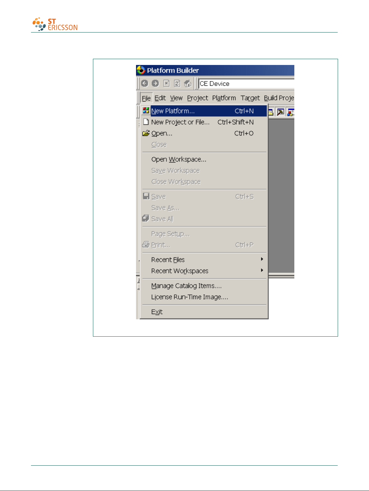
1. Install Windows CE Ver. 5.0 with your selected BSP.
After installing Windows CE Ver. 5.0, follow the steps to add the ISP176x HCD and its
dependent modules.
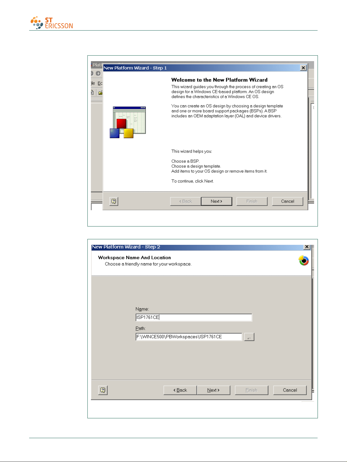
2. Create a platform workspace with your BSP.
UM10067_3 © ST-ERICSSON. All rights reserved.
User manual Rev. 03 — 12 October 2009 3 of 25
Page 4
UM10067
ISP1760; ISP1761 Win CE 5.0 User Installation Guide
Fig 1. Step 1.
UM10067_3 © ST-ERICSSON. All rights reserved.
User manual Rev. 03 — 12 October 2009 4 of 25
Page 5
UM10067
ISP1760; ISP1761 Win CE 5.0 User Installation Guide
Fig 2. Step 2.
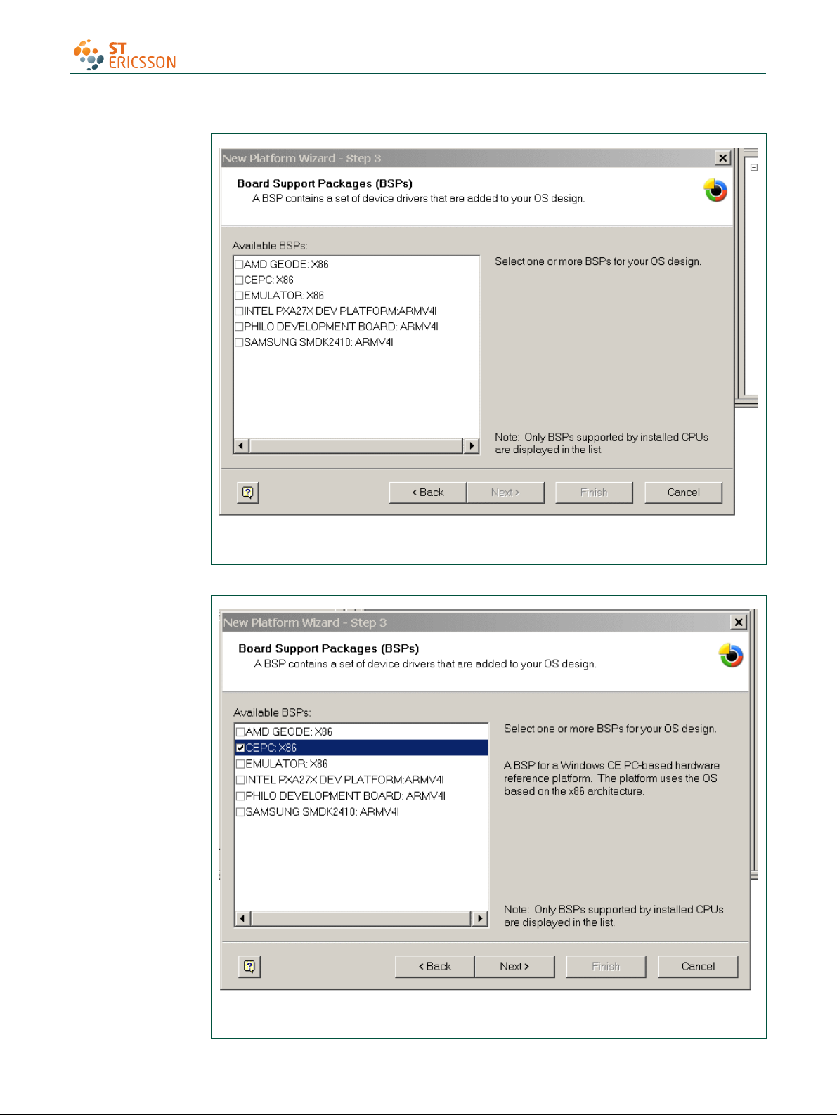
Fig 3. Step 3.
UM10067_3 © ST-ERICSSON. All rights reserved.
User manual Rev. 03 — 12 October 2009 5 of 25
Page 6
UM10067
ISP1760; ISP1761 Win CE 5.0 User Installation Guide
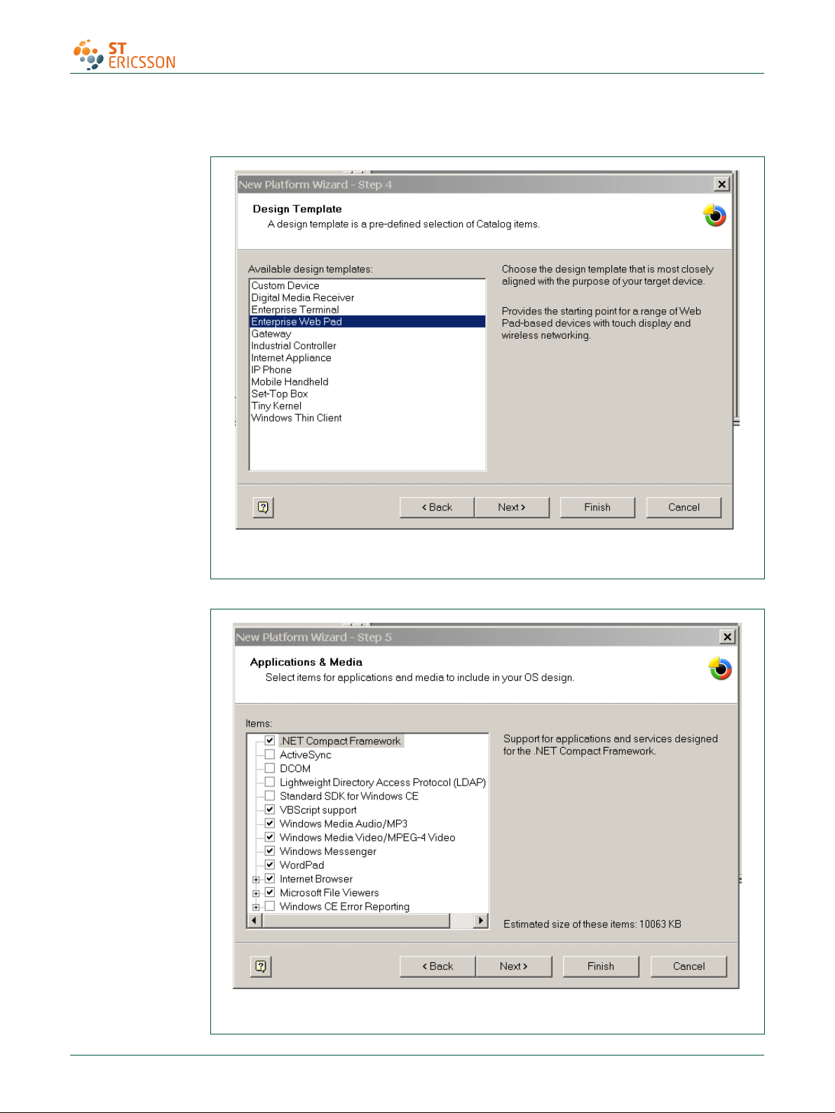
Fig 4. Step 4.
Fig 5. Step 5.
UM10067_3 © ST-ERICSSON. All rights reserved.
User manual Rev. 03 — 12 October 2009 6 of 25
Page 7
UM10067
ISP1760; ISP1761 Win CE 5.0 User Installation Guide
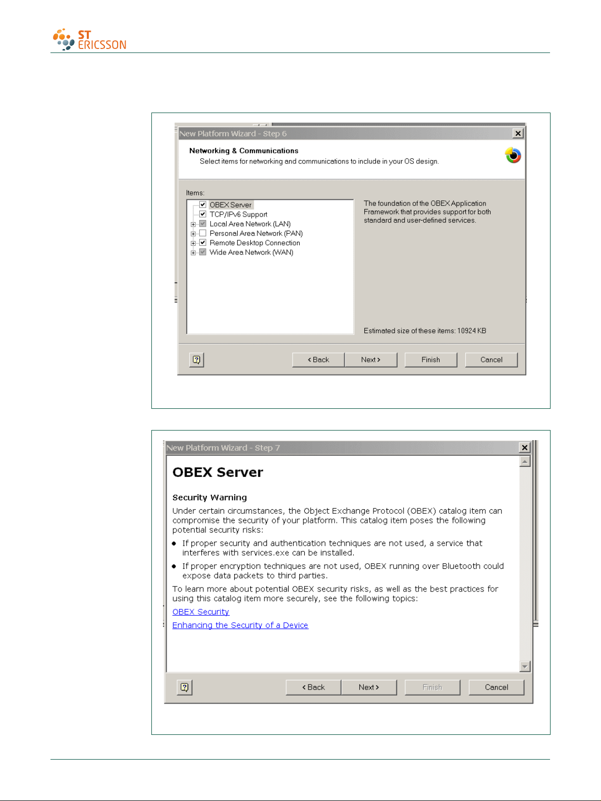
Fig 6. Step 6.
Fig 7. Step 7.
UM10067_3 © ST-ERICSSON. All rights reserved.
User manual Rev. 03 — 12 October 2009 7 of 25
Page 8
UM10067
ISP1760; ISP1761 Win CE 5.0 User Installation Guide
Fig 8. Step 8.
Fig 9. Step 9.
UM10067_3 © ST-ERICSSON. All rights reserved.
User manual Rev. 03 — 12 October 2009 8 of 25
Page 9

UM10067
ISP1760; ISP1761 Win CE 5.0 User Installation Guide
Fig 10. Step 10.
3. Refresh the catalog items.
Fig 11. Step 11.
UM10067_3 © ST-ERICSSON. All rights reserved.
User manual Rev. 03 — 12 October 2009 9 of 25
Page 10

UM10067
ISP1760; ISP1761 Win CE 5.0 User Installation Guide
Fig 12. Step 12.
Fig 13. Step 13.
UM10067_3 © ST-ERICSSON. All rights reserved.
User manual Rev. 03 — 12 October 2009 10 of 25
Page 11

UM10067
ISP1760; ISP1761 Win CE 5.0 User Installation Guide
Fig 14. Step 14.
Fig 15. Step 15.
UM10067_3 © ST-ERICSSON. All rights reserved.
User manual Rev. 03 — 12 October 2009 11 of 25
Page 12

UM10067
ISP1760; ISP1761 Win CE 5.0 User Installation Guide
Fig 16. Step 16.
Fig 17. Step 17.
UM10067_3 © ST-ERICSSON. All rights reserved.
User manual Rev. 03 — 12 October 2009 12 of 25
Page 13

UM10067
ISP1760; ISP1761 Win CE 5.0 User Installation Guide
Fig 18. Step 18.
Fig 19. Step 19.
UM10067_3 © ST-ERICSSON. All rights reserved.
User manual Rev. 03 — 12 October 2009 13 of 25
Page 14

UM10067
ISP1760; ISP1761 Win CE 5.0 User Installation Guide
Fig 20. Step 20.
Fig 21. Step 21.
Fig 22. Step 22.
UM10067_3 © ST-ERICSSON. All rights reserved.
User manual Rev. 03 — 12 October 2009 14 of 25
Page 15

UM10067
ISP1760; ISP1761 Win CE 5.0 User Installation Guide
4. Adding the ISP176x project to the platform
In this section, you will learn to add the ISP176x Host Controller catalog items to the
operating system design view. It is assumed that the platform is already created and the
ISP176x catalog files have been imported.
If you are working on the PCI bus, you need to add the PCI bus driver to route the PCI
interrupt to the ISP176x. If you are using the GPIO bus, you can ignore this step. To add
the PCI bus driver, add module Catalog\ThirdParty\ST-ERICSSON \ PCIKit.
Fig 23. Adding the component: PCI kit.
To add the ISP176x module to the platform, add module Catalog\ThirdParty\ STERICSSON\1761HostController.
UM10067_3 © ST-ERICSSON. All rights reserved.
User manual Rev. 03 — 12 October 2009 15 of 25
Page 16

UM10067
ISP1760; ISP1761 Win CE 5.0 User Installation Guide
Fig 24. Adding the component: ISP176x Host Controller.
5. Interfacing routines
The ISP176x Host Controller module is located below Microsoft defined USBD. The
ISP176x Host Controller module interacts with the ISP176x hardware located at the
bottom level and with the USBD located above this module.
Fig 25
shows interfacing the blocks of the ISP176x to an operating system.
UM10067_3 © ST-ERICSSON. All rights reserved.
User manual Rev. 03 — 12 October 2009 16 of 25
Page 17

UM10067
ISP1760; ISP1761 Win CE 5.0 User Installation Guide
OPERATING
SYSTEM
CORE USBD CLASS DRIVER AND OTHER OPERATING SYSTEM DEPENDENT UNITS
ISP176x OTG
CONTROLLER DRIVER
ISP176x HOST
CONTROLLER
DRIVER
ISP176x PERIPHERAL
CONTROLLER DRIVER
ISP176x HARDWARE ACCESS LAYER
ISP176x HARDWARE
IO INTERFACE
HARDWARE ROOT HUB
TT HUB WITH THREE PORTS
HIGH-SPEED
USB PORT
HIGH-SPEED
USB PORT
OTG PORT
OPERATING
SYSTEM
Fig 25. ISP176x system interface.
6. Customizing the software
The software architecture supports PCI and GPIO modes. In PCI and GPIO modes, read
and write registers of the ISP176x can be memory mapped. You can configure the
interrupt for the ISP176x as either edge-triggered or level-triggered using the Hardware
Mode Control register. To customize the ISP176x, refer to the ISP176xHCDConfig.h file,
located under the ‘WINCE500\3rdparty\ST-ERICSSON\phISP176xHCD\phISP176xCOM’
directory.
UM10067_3 © ST-ERICSSON. All rights reserved.
User manual Rev. 03 — 12 October 2009 17 of 25
Page 18

UM10067
ISP1760; ISP1761 Win CE 5.0 User Installation Guide
6.1 PCI bus mode
The software is tested and proven on the PLX9054 bridge. PCI bridge chip PLX9054 in
the ISP176x PCI kit is used for the PCI host to transparently access the ISP176x.
PLX9054 requests PCI bus resources, such as I/O ports, interrupt line, on behalf of the
ISP176x. PLX9054, however, can only request one interrupt line for the ISP176x.
If required, customize file P1761bus.reg under WINCE500\3rdparty\STERICSSON\PhISP176xbus\.
Change the following, depending on your PCI bridge settings:
• VendorID
• DeviceID
• SubVendorID
• SubsystemID
• Class
• SubClass
• ProgIF
For example, the P1761bus.reg file looks as follows:
; =========================================================
; USB - P1761 Bus PCI Bus Driver for PCI kit only
; =========================================================
; HC : 1: support Host Controller. 0: none
; DC : 1: support Device Controller. 0: none
[HKEY_LOCAL_MACHINE\Drivers\BuiltIn\PCI\Template\P1761BUS]
"Dll"="p1761bus.dll"
"Order"=dword:0
"Class"=dword:06
"SubClass"=dword: 80
"ProgIF"=dword:00
"VendorID"=multi_sz:"10b5"
"DeviceID"=multi_sz:"5406"
"SubVendorID"=multi_sz:"10b5"
"SubsystemID"=multi_sz:"9054"
"HC"=dword:1
"DC"=dword:0
; =========================================================
; USB - ST-ERICSSON ISP17161 driver Instance to create DCD or HCD
; =========================================================
; Used to create P1761HCD instance
UM10067_3 © ST-ERICSSON. All rights reserved.
User manual Rev. 03 — 12 October 2009 18 of 25
Page 19

UM10067
ISP1760; ISP1761 Win CE 5.0 User Installation Guide
[HKEY_LOCAL_MACHINE\Drivers\ISP176x\Instance]
"Dll"="RegEnum.dll"
; =========================================================
; USB - ST-ERICSSON ISP176xHCD driver template
; =========================================================
[HKEY_LOCAL_MACHINE\Drivers\ISP176x\Template]
"InstanceIndex"=dword:0
The driver will not be loaded, if these parameters do not match bridge settings.
6.2 GPIO bus mode
If working in GPIO mode, change registry settings of P1761HCD.dll.
Open registry file P1761HCPDD.reg under WINCE500\3rdparty\STERICSSON\phISP176xHCD\phISP176xPDD.
For example, the registry should look as follows, if you are working in GPIO mode.
Change ‘SysIntr’, ‘Irq’ and ‘MemBase’, according to your platform.
[HKEY_LOCAL_MACHINE\Drivers\BuiltIn\P1761HCD]
; "Prefix"="PEHCD"
"Dll"="P1761HCD.dll"
"Order"=dword: 2
"Class"=dword:0c
"SubClass"=dword:03
"ProgIF"=dword: 20
"IsrDll"="giisr.dll"
"IsrHandler"="ISRHandler"
"HcdCapability"=dword:4 ;HCD_SUSPEND_ON_REQUEST
"SysIntr"=dword:1f ; decimal 31 ; you change your interrupt line here
"MemBase"=dword:08000000 ;you change your Memory Base Address here
"MemLen"=dword:100000
"InterfaceType"=dword:0 ; Internal
"Irq"=dword:3 ;you change your IRQ number here
6.3 Driver loading sequence in Windows CE Ver. 5.0
After switching on the Windows CE system with the ISP176x PCI kit, PCI BIOS initializes
the PCI kit and assigns I/O resource and PCI interrupt lines as requested by PLX9054.
Windows CE Ver. 5.0 PCI bus driver PCIbus.dll is then invoked. PCIbus.dll gets I/O
resource and PCI interrupt line of the ISP176x PCI kit and obtains an interrupt ID.
PCIbus.dll searches the registry, finds the ISP176x registry template by matching registry
key ‘Class’, ‘Subclass’, ‘VendorID’, ‘DeviceID’, ‘SubsystemID’ and ‘SubvendorID’, then
loads P1761Bus.dll.
UM10067_3 © ST-ERICSSON. All rights reserved.
User manual Rev. 03 — 12 October 2009 19 of 25
Page 20

UM10067
ISP1760; ISP1761 Win CE 5.0 User Installation Guide
To ensure that PCI bus driver PCIBus.dll loads P1761 bus driver P1761Bus.dll, porting
engineer should verify that the above-mentioned registry key matches with the PLX9054
setting in the P1761bus.reg file located under directory ST-ERICSSON\PhISP176xBus.
Once P1761Bus.dll is loaded and the system loads Host Controller stack P1761hcd.dll
by checking registry setting in P1761bus.reg under directory STERICSSON\PhISP176xbus.
This loading sequence will be different if you are working in GPIO mode. P1761Bus.dll
will not be loaded in GPIO mode.
6.4 I/O address translation in Windows CE Ver. 5.0
As soon as Host Controller stack p1761hcd.dll is loaded, its platform dependent PDD
code, system.c, (under ST-ERICSSON\PhISP176xHCD\PhISP176xPDD) gets the
hardware resources, I/O port and interrupt ID, from the registry. These I/O port
addresses are in the form of physical address.
Direct hardware accesses by using the physical address from user mode device drivers
or applications are prohibited by Windows. Physical addresses must be translated into
virtual addresses using either MemMapIoSpace () or VirtualAlloc () / Virtual Copy. The
translation can also be done by new Windows CE Ver. 5.0 function
BusTransBusAddrToVirtual ().
7. Building an image
To build an image, select BuildOS -> Build and Sysgen.
Fig 26. Building an image.
8. Creating boot disk for x86 SDB
To create a boot floppy disk for an x86 SDB:
1. Navigate to the %ProgramFiles%\Windows CE Platform Builder\5.00\CEPB\Utilities
directory, and then run WebSetup.exe to install utility programs to the default
Microsoft Windows directory on your PC. You only need to install WebSetup.exe
once.
2. On your PC, insert a blank 3.5-inch floppy disk in the floppy disk drive.
UM10067_3 © ST-ERICSSON. All rights reserved.
User manual Rev. 03 — 12 October 2009 20 of 25
Page 21
UM10067
ISP1760; ISP1761 Win CE 5.0 User Installation Guide
3. From the %ProgramFiles%\Windows CE Platform Builder\5.00\CEPB\Utilities
directory, run CEPCBoot.144. You can also run CEPCBoot.144 from the command
line.
4. If your floppy disk is not blank and formatted, check format before making disk box in
the Web Image NT window. This causes WebSetup.exe to format the boot floppy
disk with MS-DOS 6.22 before copying the CEPCBoot.144 disk image to the boot
floppy disk.
5. In the Web Image NT window, choose the A: drive. This copies the CEPCBoot.144
disk image to the boot floppy disk.
6. Choose Cancel to close the Web Image NT window.
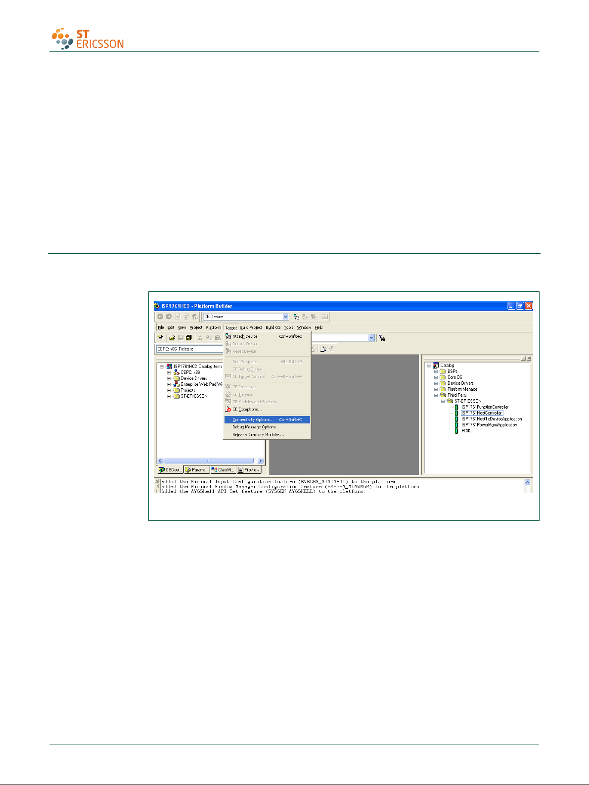
9. Connecting to x86 SDB target
1. On the Target menu, select Connectivity Options.
Fig 27. Step 1.
2. If you want to download the image through Ethernet and want the debugger to be
KdStub, set Debugger to KdStub, Download and Transport to Ethernet.
UM10067_3 © ST-ERICSSON. All rights reserved.
User manual Rev. 03 — 12 October 2009 21 of 25
Page 22

UM10067
ISP1760; ISP1761 Win CE 5.0 User Installation Guide
Fig 28. Step 2.
3. Choose your device boot name or IP address.
Fig 29. Step 3.
4. Select Attach Device to download the image to the target.
UM10067_3 © ST-ERICSSON. All rights reserved.
User manual Rev. 03 — 12 October 2009 22 of 25
Page 23

UM10067
ISP1760; ISP1761 Win CE 5.0 User Installation Guide
10. References
11. Glossary
Fig 30. Step 4.
[1] Universal Serial Bus Specification Rev. 2.0
[2] ISP1760 Hi-Speed USB host controller for embedded applications data sheet
[3] ISP1761 Hi-Speed USB On-The-Go controller data sheet
[4] Enhanced Host Controller Interface Specification for Universal Serial Bus Rev. 1.0.
Table 1. Abbreviations
Acronym Description
API Application Programming Interface
BIOS Basic Input Output System
BSP Board Support Package
GPIO General Purpose Input/Output
HAL Hardware Abstraction Layer
HCD Host Controller Driver
IP Internet Protocol
MSI Microsoft Installer
PC Personal Computer
PCI Peripheral Component Interconnect
USB Universal Serial Bus
USBD Universal Serial Bus Driver
UM10067_3 © ST-ERICSSON. All rights reserved.
User manual Rev. 03 — 12 October 2009 23 of 25
Page 24

UM10067
ISP1760; ISP1761 Win CE 5.0 User Installation Guide
12. Legal information
Please Read Carefully:
The contents of this document are subject to change without prior notice. ST-Ericsson
makes no representation or warranty of any nature whatsoever (neither expressed nor
implied) with respect to the matters addressed in this document, including but not limited to
warranties of merchantability or fitness for a particular purpose, interpretability or
interoperability or, against infringement of third party intellectual property rights, and in no
event shall ST-Ericsson be liable to any party for any direct, indirect, incidental and or
consequential damages and or loss whatsoever (including but not limited to monetary losses
or loss of data), that might arise from the use of this document or the information in it.
ST-Ericsson and the ST-Ericsson logo are trademarks of the ST-Ericsson group of
companies or used under a license from STMicroelectronics NV or Telefonaktiebolaget LM
Ericsson.
All other names are the property of their respective owners.
© ST-Ericsson, 2009 - All rights reserved
Contact information at www.stericsson.com under Contacts
www.stericsson.com
UM10067_3 © ST-ERICSSON. All rights reserved.
User manual Rev. 03 — 12 October 2009 24 of 25
Page 25

UM10067
ISP1760; ISP1761 Win CE 5.0 User Installation Guide
13. Contents
1. Introduction ......................................................... 3
2. Installing the ISP176x host software ................. 3
3. ISP176x HCD Windows CE Ver. 5.0 operating
system design ..................................................... 3
4. Adding the ISP176x project to the platform .... 15
5. Interfacing routines ........................................... 16
6. Customizing the software ................................. 17
6.1 PCI bus mode ...................................................... 18
6.2 GPIO bus mode ................................................... 19
6.3 Driver loading sequence in Windows CE
Ver. 5.0 ............................................................. 19
6.4 I/O address translation in Windows CE
Ver. 5.0 ............................................................. 20
7. Building an image ............................................. 20
8. Creating boot disk for x86 SDB ........................ 20
9. Connecting to x86 SDB target .......................... 21
10. References ......................................................... 23
11. Glossary ............................................................. 23
12. Legal information .............................................. 24
13. Contents ............................................................. 25
© ST-Ericsson 2009. All rights reserved.
For more information, please visit: http://www.stericsson.com
For document related queries, email to: wired.support@stericsson.com
Date of release: 12 October 2009
Document identifier: UM10067_3
 Loading...