

Page 1

LBI-33058
Operator’s Manual
TRUNKE D MDX
MOBI LE RA DIO
ericssonz
Page 2

TABLE OF CONTENTS
Page
SAFETY INFORMATION . . . . . . . . . . . . . . . . . . . . 5
SAFE DRIVING RECOMME ND ATIONS FOR USERS
OF MOBILE RADIOS . . . . . . . . . . . . . . . . . . . 6
INTRODUCTION . . . . . . . . . . . . . . . . . . . . . . . . 7
CONTROLS, INDICATORS, AND DISPLAYS . . . . . . . . . 8
CONTROLS . . . . . . . . . . . . . . . . . . . . . . . . . 8
DISPLAY INDICATORS . . . . . . . . . . . . . . . . . . 13
DISPLAY ALP H A INDICATORS . . . . . . . . . . . . . 13
Full Length Indicators . . . . . . . . . . . . . . . . . 14
Abbreviate d Indicators . . . . . . . . . . . . . . . . . 14
ALERT TONES . . . . . . . . . . . . . . . . . . . . . . . . . . 15
TRUNKED ALERT TONE SETS . . . . . . . . . . . . . . 16
Single Alert Tones . . . . . . . . . . . . . . . . . . . 16
Continuou s Alert Tones . . . . . . . . . . . . . . . . 17
OPERATING NOMENCLATURE . . . . . . . . . . . . . . . . 17
TRUNKED OPERATION . . . . . . . . . . . . . . . . . . 17
CONVENTIONAL OPERATION . . . . . . . . . . . . . . 17
DEFINITION OF TERMS . . . . . . . . . . . . . . . . . . 18
Wi de Area System Operation (Optional ) . . . . . . . 18
ProSound . . . . . . . . . . . . . . . . . . . . . . 19
Telephone Interconnect . . . . . . . . . . . . . . . . . 19
BASE/UNIT OPERATION . . . . . . . . . . . . . . . . . 19
OPERATING THE RADIO . . . . . . . . . . . . . . . . . . . . 19
TURNING THE RADIO ON . . . . . . . . . . . . . . . . 19
NOTICE!
Repairs to this equipment should be made only by an authorized service
techn ician or fac ility desi gnate d by the suppli er . Any repa irs, alt eratio ns
or substi tut io n of rec om mend ed pa rt s ma de b y t he use r to t his e qu ipm ent
not approved by the manufacturer could void the user’s authority to
oper ate the eq uip me nt in addi ti on t o the man ufactur er’s warranty.
NOTICE!
This manua l cove rs E ric sson and Ge ne ra l Elec tri c produ ct s
manufa c tur ed and sold by Eri csson In c.
This manual is published by Ericsson Inc., without any warranty. Improvements and changes to this manual necessitated by
typographical errors, inaccuracies of current information, or improvements to programs and/or equipment, may be made b y
Ericsson Inc., at any time an d without n otice . Such changes will b e incorportat ed in to new editi ons of this man ual. No part of this
manual may be reproduced or transmitted in any form or by any means, electronic or mechanical, including photocopying and
recording, for any purpose, without the express written permission of Ericsson Inc.
Copyright© May 1995, Ericsson Inc.
2
Page 3

TABLE OF CONTENTS (CO N’T)
Page
SELECTING SYSTEM/GROUP . . . . . . . . . . . . . . 20
Group Selection . . . . . . . . . . . . . . . . . . . . 20
System Selection . . . . . . . . . . . . . . . . . . . 20
FRONT PANEL SQUELCH ADJUST MENT . . . . . . . 20
INTERNAL /E XTERNAL SPEAKER . . . . . . . . . . . 20
MICROPHONE PUBLIC ADDRESS OPERATION . . . 21
TRUNKED OPERATION . . . . . . . . . . . . . . . . . . . . 21
PLACING A TRUNKED DISPATCH CALL . . . . . . . 21
MANUALLY ENTE RING A GROUP ID
(System Mode l Only) . . . . . . . . . . . . . . . . . . . . 22
RECEIVING AN EMERGENCY ME SSAGE . . . . . . . 23
From The Selected Group . . . . . . . . . . . . . . . 23
From A Scanned G roup . . . . . . . . . . . . . . . . 23
SENDING AN EMERGENC Y ME SSAGE . . . . . . . . 23
CLEARING AN EMERGENCY . . . . . . . . . . . . . . 24
SPECIAL CALLS . . . . . . . . . . . . . . . . . . . . . . 24
Placin g A Telephone Interc onn ect Cal l
(On Systems Eq uip pe d W i th Inter co nne c t Hardwa re ) 24
Answering A Telephone Interconnec t Call . . . . . . 25
Placin g A Specia l Call To Another Radio . . . . . . . 25
Receiving An Individual Call . . . . . . . . . . . . . 25
GROUP SCAN OPERATION . . . . . . . . . . . . . . . 26
Adding/Deleting To/From Sca n . . . . . . . . . . . . 26
Starting Or Stoppin g Scan . . . . . . . . . . . . . . . 26
RECEIVING A CAL L . . . . . . . . . . . . . . . . . . . 26
ENDING A CALL . . . . . . . . . . . . . . . . . . . . . 27
MOBILE DATA TERMI NAL INTE R FACE (OPTIONAL) 28
SCAN LOCKOUT MODE . . . . . . . . . . . . . . . . . 29
DATA LOCKOUT MODE . . . . . . . . . . . . . . . . . 29
STATUS OPERATION . . . . . . . . . . . . . . . . . . . 29
MESSAGE OPE R ATION . . . . . . . . . . . . . . . . . . 30
DYNAMIC REGROUP OPERATION . . . . . . . . . . . 30
Emergency Operation . . . . . . . . . . . . . . . . . 31
AEGIS OPER ATIO N . . . . . . . . . . . . . . . . . . . . . . 31
VOICE MODES . . . . . . . . . . . . . . . . . . . . . . 31
AEGIS DIGITAL MODE . . . . . . . . . . . . . . . . . . 32
Scanne d Group Calls . . . . . . . . . . . . . . . . . 32
CONVENTIONAL OPERATION . . . . . . . . . . . . . 32
Outside Address . . . . . . . . . . . . . . . . . . . . 32
DIRECT MODE OPERATION . . . . . . . . . . . . . . . 32
3
Page 4

TABLE OF CONTENTS (CO N’T)
Page
OPTIONS . . . . . . . . . . . . . . . . . . . . . . . . . . . . . 33
FREQUENTLY CALLED NUMBERS . . . . . . . . . . . . . 34
WARRANTY . . . . . . . . . . . . . . . . . . . . . . . . . . . 35
OPERATING TIP S . . . . . . . . . . . . . . . . . . . . . . . . 36
4
Page 5

SAFETY INFORMATION
The operato r of any mobile radio should be aware of ce rtain hazards
commo n to the opera ti on of ve hi cula r ra di o tran smi ssi ons.
A list of po ssibl e ha za rds ar e:
1. Explosive Atmosphe res
Just as it is dangerous to fuel a vehicle with the motor running, be
sure to turn the radio off while fueling the vehicle. Do not carry
contai ners of fue l in the trunk .
2. Interferenc e to Vehicular Elec troni cs Systems
Electronic fuel injection systems, electronic anti skid braking systems, etc., are typical of the type of electronic devices that may
malfun ction due to th e lack of prote ction from radio fre quency en ergy
present when transmitting. If the vehicle contains such equipment,
consult the dealer for the make of the vehicle and enlist his aid in
determining if such electronic circuits perform normally when the
radi o is tra ns m it ti ng.
3. Dynamite Blasting Caps
Dynamit e blasting c aps may be caused to expl ode by operating a ra dio
within 50 0 feet of the blastin g caps. Alwa ys obey the "Turn O ff Two
Way Radios" signs posted where dynamite is being used. When
transp ort ing blasti ng c ap s in your veh ic le:
a. Carry the blasti ng c a ps in a closed metal box wit h a soft lining.
b. L e ave t he r ad i o OFF whenever the blasting caps are being put
into or removed from the vehicle.
4. Radio Fre que ncy Ene rgy
To prevent burns or related physical injury from radio frequency
energy, do not operate the transmitter when anyone outside of the
vehi cl e is wi th in t wo fe et of th e antenna .
5
Page 6

5. Liquefied (L P) Ga s Powere d Vehicles
Mobile radio installations in vehicles powered by liquefied petroleum
gas with the LP gas container in the trunk or other sealed-off space
withi n the int erior of the ve hicl e must co nform to the stand ard whic h
requires that:
a. The space contai ni ng the radi o eq uip me nt shal l be isol ate d by a
seal from the space containing the LP gas container and its
fittings.
b. Outside fi lling connec tions shall be used for t he LP gas con tainer .
c. The LP gas containe r shall be vented to the ou tside of the vehic le.
SAFE DRIVING RECOMMENDATIONS FOR USERS OF MOB ILE
RADIOS
Read the literature on the safe operation of the radio.
• Keep both hands on the steerin g wheel and the m icrop hone in it s crad le
whenever the vehicle is in motion.
• Place calls onl y when veh icle is stoppe d. Use recal l diali ng to spee d the
time it takes to call.
• When ta lking fro m a moving ve hicle is unavoida ble, drive in the sl ower
lane. Keep conversations brief.
• If conversation requires taking notes or complex thought, stop the
vehicle in a safe place and co ntinue the call.
Whene ver using a mobi le radio exerc i se c aution.
6
Page 7

INTRODUCTION
This manua l descr ibe s how to use the T r unke d MDX Mob ile R adio. The
MDX is a synthesized, microprocessor-based, high performance mobile FM
radio providing reliable two-way communications in trunking environments.
Direct mobile to mobile communication, when out of repeater range, is also
provided.
In a trunked environment the user selects a communications system and
group. In this mode, audio channel selection is transparent to the user and is
control led via digital commun ication with the system cont roller . This provides
advanc ed progra mm able feature s and fast acc ess to com munic ati on cha nnels.
In the trunke d m odes of opera tion th e user c an pro gra m th e ta lk gro ups to
transmit and receive Aegis Digital Voice or the highly secure Aegis VGE
Encrypt e d Digit al Voi ce.
The exact operation of the radio will de pend on t he operating mode, the
radio’ s progra mming , and the particu lar radio system . Most feature s describe d
in this ma nua l ma y be e nabl e d o r disabled th roug h progr am m in g. Co nsult the
system a dmini stra tor for the part icul a r fea ture s tha t a re pro gra mme d into you r
MDX radio.
7
Page 8

CONTROLS, INDICATORS, AND DISPLAYS
The MDX Scan radio with an internal speaker contains ten buttons, an
eight cha racter DOT MATRI X display and seven indica tors. The MDX Syste m
radio conta ins ten buttons, an eight character DOT MA TRIX displa y and seven
indicators along with a twelve button keypad. The system radio uses an
external speaker. In addition, there are ti me s when part of the eigh t character
displa y is used to displa y t he rad io stat us. Backlighting on butt ons il lum i na te
Digital Leg ends.
CONTROL S
POWER Momentary push-push switch. Press once to turn
the radio ON. Press agai n to turn the radio OFF.
VOLUME The momentary switches (auto ramping) VOL-
UME + and VOLUME -. Beeps each time the
VOLUME button is pressed, excep t when a call is
in process. Hold the button (up or down) to auto
ram p the vol um e .
MENU Momentary switch. The MENU button is used to
access options on the MDX mobile. Menu operation is coupl e d wit h the G ROUP/ SEL button and
the CLR button. To increment from one menu
selection to the next, simply press and release the
MENU button. Press the CLR button to return to
normal operation. The menu choices are listed
below with a description of how to change the
choices (Note: You may have some or all of these
menu c hoices pro gra mmed i n your ra dio, and the y
may be programmed in a different order than presen te d here).
SPECIAL CALL: Press the MENU button until
"SPC CALL" appears in the display. Pressing the
PTT c auses t he la st se lecte d spec ial ca ll to be sen t.
To review or change the selection, use the
GROUP/SEL button to view/change the special
call selection. Up to 25 phone numbers and individual de code n umbers ca n be stored in the Spec ial
Call me nu. Whil e the desired num ber is disp layed,
press the PTT switch to initiate the call.
8
BACKLIGHT: Press the MENU button until
"BRIGHT" appears in the display. To change the
state o f t he bac kl ight pres s th e G ROUP /SEL + o r
- button.
Page 9

PUBLIC ADDRESS: Press the MENU button
until "PUB ADDR" appears in the display. Press
PTT to transmit in PA mode.
SCAN ADD/DELETE : Pre ss the MENU button
until "SCAN A/D" appe a rs in the display. Use the
GROUP/ SEL- button to step through the group
selections for the current system. Use the
GROUP/SEL + button to change the scan state.
An "S" is illuminated to the right of the display if
the group/c ha nne l has SCAN enab le d.
ALARM ON/OF F: Press the MENU butt on un til
"ALM ON" or "ALM OFF" appears in the display .
Press the GROUP/SEL + or - buttons until the
desired state is selected. (Note: This enables or
disables the external alarm; e.g. horn or lights.)
STATUS: Press the MNU but ton until "STA T US"
appears in the display. To review or change the
selection,use the GROUP/SEL keys to
view/change the selection of the status message.
When the d esired status is displ ayed, pres s the PTT
switch to initiate the stat us tra nsm ission .
MESSAGE: Press the MNU button until "MES-
SAGE" appears in the display. To review or
chan ge t he s elec tion , us e th e GROUP/SEL keys
to view/change the selection of the message.
When the desired message is displayed, press the
PTT swit ch to initiate the message transmission.
SCN Momentary switch. Press the SCN button to en-
able or disab le scan o perati on. The SCN indicato r
will light when scan is enabled. Pressing and
holding the SCN but ton whi le on a worki ng chan nel will permit the user to adjust the squelch se ttin g
from the front panel by using the VOLUME ramp
switch to open and clo se the squel ch .
9
Page 10
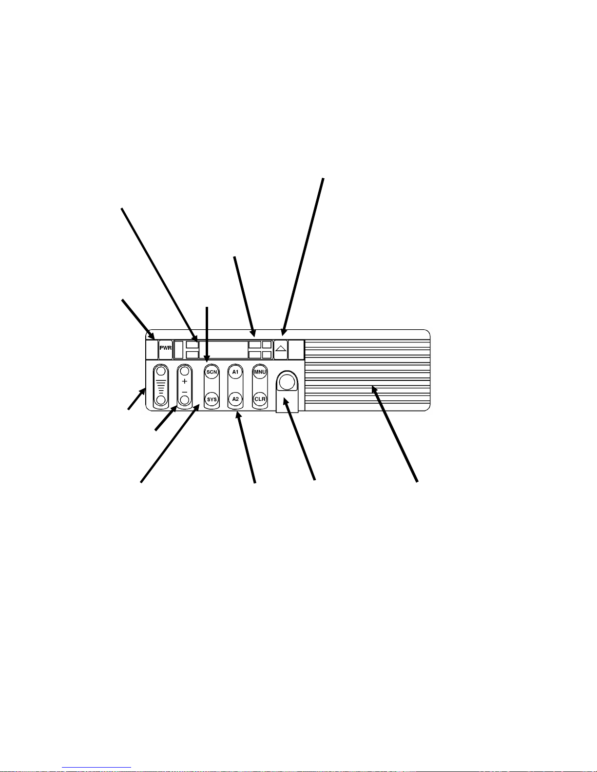
CONTROLS AND INDICA T ORS
8-Characte r
Alphanumeric Dot
Matrix LED
allows you to identify
group and system
selections by
descriptive names.
Group/area/system
names, telephone
numbers, menu
options, and status
information are
displayed here.
PWR
MENU button allows
access to functions
and options,
including
pre-programmed
telephone
interconnect and
individual radio calls;
scan add/delete for
modifying the radio’s
scan list; and alarm
on/off for the
external alarm option
that uses your horn or
head lights to signal
an incoming call.
Scan Button
Emergency ID/
Alarm (optional)
sends an emergency
alert and identifying
code to the
dispatcher. If no
emergency function
is required, this can
be programmed as a
"HOME" switch.
VOLUME
Group/SEL
Ramp
System Switch scrolls
through the names of
systems programmed
into the radio,
displaying them on
the Dot Matrix display.
Two Flex Keys
give you one-touch
access to the menu or
optional features.
Optional keycaps are
available to identify
the functions of
pre-programmed
buttons, including
Special Call, Scan
Add/ Delete, Public
Address, Home
System/Group,
External Alarm, and
display brightness.
Front-Mounted
Microphone
Connector provides
easy access to the
microphone and
programming
capabilities.
Figure 1 - MDX Scan Radio
Front Mount
Speaker with 4 watts
of audio. An optional
10-watt external
speaker is also
available, for use in
noisy environments.
10
Page 11

8-Character
Alphanumeric Dot
Matrix LED
allows you to identify
group and system
selections by
descriptive names.
Group/area/system
names, telephone
numbers, menu
options, and status
information are
displayed here.
MENU button allows
access to functions
and options,
including
pre-programmed
telephone
interconnect and
individual radio calls;
scan add/delete for
modifying the radio’s
scan list; and alarm
on/off for the
external alarm option
that uses your horn or
head lights to signal
an incoming call.
Emergency ID/
Alarm (optional)
sends an emergency
alert and identifying
code to the
dispatcher. If no
emergency function
is required, this can
be programmed as a
"HOME" switch.
Flex Key
give you one-touch
access to the menu or
optional features.
Optional keycaps are
available to identify
the function of the
pre-programmed
button, including
Special Call, Scan
Add/ Delete, Public
Address, Home
System/Group,
External Alarm, and
display brightness.
PWR
VOLUME
Group/SEL
Ramp
System Switch scrolls
through the names of
systems and/or
channels programmed
into the radio,
displaying them on
the Dot Matrix display.
Scan Button
GROUP button
permits group ID
entries to be made
using the 12 button
system keypad.
CLEAR
button
Front-Mounted
Microphone
Connector provides
easy access to the
microphone and
programming
capabilities.
System Keypad
Permits telephone
interconnect and
DTMF overdial as
well as group and
individual call
entries.
Figure 2 - MDX System Radio
11
Page 12

CONTROLS (CO NT’D)
SYS Momentary switch. The SYS (SYSTEM) button is
used to select system changes. System may be
incremented by pressing and releasing the SYS
button. Alternately, when the display shows the
System name, the GROUP/SEL buttons may be
used to increment or decrement the system selections. (NOT E: The ra dio may be programme d with
wrap around on the system selection; this would
allow the radio to switch from the highest to lowest
system with one c hange instead of ra mping all the
way through the list. )
GROUP/SEL Ramp Switch. The GROUP /SEL but ton is u sed t o
increment or decrem e nt the curre nt group/channel
selection. It is also used as described above to
increment /decre m ent the System.
CLR Momentary switch. The CLR button is used to exit
from the menu operation or end a special/individual call.
HOME/
EMERGENCY
Momentary switch. The HOME or EMER-
GENCY button is used to select a home system,
group, or channe l. The radio may be progr amm ed
to reve rt to a part icular system and /or grou p within
the selected or home system. It may also be programmed to send an emergency message when
pressed and held for approximately one second
(either on the selected system/group or on the
Home system/group).
FLEX KEYS
A1
The aux butt ons are used to a ccess f reque ntly used
menu selections quickly. They can also be programmed as a HOME or Group/System, no Data
Toggle b utt on, External Alar m, Public Address or
PriVaTe mode.
GRP Momentary switch. On Systems radios the GRP
button is used to enter group ID from the 12 butto n
sytem keypad.
NUMERIC KEY S
1-9 , 0, *, #
On Sy stem ra dio, the twelve but ton keyp ad perm its
telep hone interconne ct and DTMF overdi al as well
as Group and Individual ID call entries.
12
Page 13

DISPLAY INDICATOR S
The radio’s displa y is shown be low. The character line is used to displa y
system or area and group or channel names and also operational messages to
the user. The line contains eight Dot Matrix LED characters. The 7 status
indicato rs are use d to show the various operatin g condi ti ons of the radi o.
Figure 3 - Sample MDX Displ ay
TX On indicates the ra di o is transm it ti ng.
BSY Ligh ts when a group is act ive (tr unke d syste m) or
when a channel is busy (conventional system).
Flashes wh en a call is queued on a trunked system.
SCN ON indicates scan is enabled (for radios which
have this feature).
S ON indica tes group/channe l in scan l ist.
P1 ON indic ates se lec ted c hanne l is a priori ty c hann el
(conv en ti ona l only).
P2 ON ind ica te s se le c ted c ha nne l is a pri ori ty 2 ch an -
nel (conventional only).
PVT ON indicates selected channel has been pre-pro-
grammed for Aegis operation. Flashes indicates
rec ei vi ng a n en crypted digital voice cal l.
NOTE
In trunke d operation the P1 & P2 indica tors can be programme d to flash
when the radio has received an individual call. Display shows "C* to
show receipt of I-CALL.
DISPLAY ALPHA INDICATORS
The radio is capable of displaying status indicators in the alpha display.
Some of these me ssag es wil l use the enti re displ ay while oth er s use only two
or three cha racte rs. When the short m essage is displaye d it may be on the right
13
Page 14

or left of the display (PC programmable). It is separated from the normal
informa tion with an indicato r such as an asteri sk ("*" ).
Full Length Indicators
**INDV** Displayed when your unit receives an individual
call from another unit.
ID##### If programme d, displayed when your unit rec eives
an individua l call where ##### is the unit ID of the
calling radio. (Note: If the ID is in your Special
Call list, you may choose to show an 8 character
name i nste a d of th e number.)
PHN CALL Displayed when your radio receives a t elephone
call from the trunke d syste m .
DATACALL Displayed when your radio is involved in a data
call .
*NO DATA Displayed when your radio is in the data disabled
state.
* NC * Displayed when no control channel is found on a
trunked syste m.
ALL CALL Displaye d when re cei vin g a system wide call.
*AGENCY* Displayed when receivin g an Agen cy Call.
*FLEET* Displaye d when re cei vin g a Fleet Call.
EMERGNCY Displayed stea dy when opera tor declare s an emer-
gency (optional), flashes when another user de-
clares an emergency .
BOOT DSP Displ ayed at po wer on in r adios eq uipped for Aegis
operation. Indicates initialization of Digital Voice
Module.
LOAD KEY Displayed when VGE encryption keys are being
uploaded to the Digital Voice Module.
Abbreviate d Indic ato rs
F* Displaye d on radios defined in the PC p rogramme r
14
as supervisory when the trunked system is in fail-
soft mode. (Note: In failsoft mode, trunked dis-
patch operations is fully operational but
interconnect may not be possible.)
Page 15

C* Displayed when an individual call has been re-
ceived and not answer ed. By selecting Special Call
in menu mo de, the cal l can be re called for re turn at
a later time. (Note: The call is not saved through
a power cycle.)
E* Displayed when an active voice call on a trunked
system is in an emer ge nc y sta te.
ALERT TONES
The trunked MDX radio generates a set of unique alert tones to indicate
operat ing status. The follo wing sec tion iden tifies an d descri bes the ale rt tones
used in the MDX radio for trunke d applic atio ns.
SELF CHECK
TEST ALERT
One beep is sounde d afte r the ra dio is tu rned on to
indicate that the radio has passed the self diagnostic
test. Optional in PC programmer .
CALL
ORIGINATE
ALERT
If programmed, a short tone is sounded whenever
the Push-To-Talk (PTT) button is keyed and the
rad io has acq uired a channe l. This tone ind icates
the user may begin communications.
AUTOKEY When the PTT is keyed to place a call on the
system, but the PTT is released before getting to
the channel (e.g. a queued call), the radio automatically ke ys on the channel when it gets the assignment. The radio generates a long beep and holds
the transm itter keye d for two seconds. Pressing the
PTT b utton keeps the channel and sends the me ssage before this two second time-ou t has expired.
OUT OF RANGE /
SYSTEM
INOPERATIVE
A single low pitche d tone wil l sound imm edia tel y
after the PTT switch is keyed indicating the radio
is out of range of the repeater. The radio tries to
place the call for a short period (3 seconds) after
the initial attempt. The radio generates a second
low pitched tone when it gives up trying to place
the call. The system is off the air or the radio nee ds
servicing when the radio is within calling range,
and these tones are heard.
CALL RECEIVED If programmed, a single alert tone sounds when a
group call is received and a two tone alert (one high
followed by one low tone) is sounded for an individua l ca ll .
15
Page 16

CALL DISABLED
ALERT
You will hear a cont in uous l ow pit che d t one whe n
your radio is set to an Rx (decode) only
group/channel and you press PTT on the microphone . This tone indi cates tha t you ar e not allowe d
to plac e a cal l on this setting.
CARRIER CONTROL
TIMER
The Car rier Contr ol Tim er al ert is a low pi tched
tone you will hear whenever you have kept the
PTT button continuously pressed for a pre-programmed length of time. Four warning beeps preceed the tone and transmitter shutdown. The
transmitter shuts down when the steady low
pitched tone starts, interrupting communications.
To maintain communications, release and re-key
the microp hone. Thi s resets the timer an d turns the
transmitter back on. The CCT is a built in precaution against ex tende d use of the system .
TRUNKED ALER T TONE SET S
There are two trunked alert tone set s: single and continuous. The trun ked
MDX radio can be programme d to use either set.
Single Al ert Tones
CALL QUEUED If one short, high pitched tone sounds after the
transmitter is keyed, it indicates the system has
placed the request in a queue. This tone sounds at
bo th the tran smitting and r eceiving end th at a call
is forthcoming. If the PTT is unkeyed whi le in the
queue, the radio will automatically key push-totalk when a channel becomes available (see
AUTOKEY).
SYSTEM BUSY If you key the PTT bar and hear three short, me-
CALL DENIED A single low pitch beep will sound when the PTT
16
dium pitched tones, it indicates that the receiving
party is alrea dy on the system or the system is busy
and its q ueue is full . Y ou must re-key l ater to access
the system.
switch is keyed and the request is denied by the
system. This happens if the unit is an invalid user
or if the uni t is requesting an unavailabl e servi c e.
Page 17

Continuous Ale rt Tones
CALL QUEUED If you hear two short, high pitched bee ps after you
key the microphone, the system has placed your
request in a queue. The tones sound at both your
transmitting unit and the receiving unit(s). This
indicates to the receiving unit(s) that they will
recei ve a call s hortl y . T hese tones will repe at ev er y
half secon d a t the c a lle r’ s r ad io unt il Pu sh-To-Tal k
is released. If you unkey the microphone while in
queue, your radio will autokey when a channel
becomes available [Automatically key (push-totalk), see AUT OKEY] .
SYSTEM BUSY If you key the m icrophone and hear f our s hort, l ow
pitc hed b eep s, the r ec eiv ing pa rt y is al re ad y o n t he
system or the system is busy and its queue is full.
The busy ton e sequ en ce is re pea te d as long a s yo u
continu e to press the PTT switc h. You must r elease
and re-key the PTT switch to access the syste m.
CALL DENIED If you hear five long low pitched tones when you
key the microphone, y our request has been denied
by the system. this happens if you are an invalid
user or if you are requesting an unavailable service.
END OF "CALLBACK" After receiving a Multi-Group Decode, Scan or
Individual Call, you will have a pre-programmed
period to respond back to the caller. At the end of
this period , the radio will sound two shor t tones to
ind icate a re turn to normal op erat ion, and the received call can no longer be answered directly .
OPERATING NOMENCL ATURE
TRUNKED OPE RATION
Tru nke d ope ra tion ref er s to the use of a set of r ad io fre que nc y c hanne l s by
multiple user groups. Users may place and receive calls to single or multiple
users without being moni to re d by othe r users (or grou p) on the system .
CONVENTIONAL OPERATION
All radios o n a convent ional system operate in one of two modes: repeate d
or talk-around. T alk-around (also referred to as "direct mode") provid es a direct
radio-to-radio short-range communications link. It is intended to maintain
communications outside of the main system coverage area. Trunked features
(such as call queuein g and system scan) are not available in conventional mode.
Conventi ona l mode oper at io n shoul d only be used for testi ng pur pose s.
17
Page 18

DEFINITION O F TERM S
System The term system refers to the particular group of
station re pea ters and set of gro up/spec ial cal ls providing service to the radio. Radios can be preprogramm ed to work in diff erent syste ms by changing
the systems selection or through wide area roaming.
Group Or
Subfleet
A group of users share the same preprogrammed
group identification number in their radios. All
rad ios in the same group rec eive cal ls pl aced by
any one radi o in the group .
Fleet A fleet of users consists of multiple groups (sub-
fleets). Radios can be preprogrammed to make
fleet calls to simultaneously access multiple user
groups.
Agency An agency is composed of multiple fleets. Radios
can be preprogrammed to initiate agency calls to
access multiple fleets.
Individual Call Every radio in the system has been assigned a
preprogrammed, unique individual identification
code. A radio can be programmed to individually
call another particular radio from the S peci al Call
Menu.
Wide Ar ea System Oper ation (O ptional)
This func tion applie s when systems ar e networked together in a mult i-site
configuration. In this mode, calls are automatically routed to the proper system.
You may notice a delay when you press the PTT button while the system is
connecting t he corre ct sites. The BS Y indi ca tor will be on, indica ting you are
on the voice channel. In this mode, you can release and press PTT again to
override the del ay. This gets you onto the system , but does not guarantee that
everyon e will hear the message.
When in the multi- site mode , your radi o may be prog ra mme d to look fo r
alternate systems when you go out of range of the currently selected system.
If an alternate system is found, the radio locks onto the system and
automa ticall y select s the correct informa tion for this new syste m. Alterna tel y ,
the radi o may be progra mm ed to reve rt to a conve ntiona l ch anne l when o ut of
ran ge of th e tr u n k e d system.
18
Page 19

Each trunke d syst em may a lso ha ve a priority tru nke d sy ste m associ at ed
with it when set to a system with a priority system programmed, the radio
periodi cal ly che cks for the pr iorit y syste m. If found, it au toma tical ly swi tche s
to tha t syst em. Th e tim er i s re set eve ry t ime the PTT butto n i s pr essed t o avoi d
inter ru pting a conversa ti on.
ProSou nd
The radio may be programmed for ProSound system scan operation for
multi-site applications. ProSound scanning is an enhanced replacement for
wide area system scanning. This algorithm insures that the radio continually
receives high quality audio. When the selected system degrades to a
pre-progr am med lev el, th e ra dio begi ns se arch ing for the best a djace nt syste m
on a part time basis. Once a better system is found, the radio changes to the
new system and sounds a tone. Should the control cha nnel be lost completel y ,
the radio will scan the adja cen t system s unti l a suitable one is found .
Telephone Interconnect
This featu re allows you to init iate preprogram med Special Cal ls or receive
telephone calls through you r radio if the system is configure d for this ope ration.
BASE/UNIT OPERATION
This pre-p rogram me d option is used in some fleet s so units c an only he ar
and talk to a base di sp at c h unit , not to other radios in th e group. In this mode
of ope ra tion, when a ra di o in a par ti cu la r gr oup is t al ki ng t o the ba se di sp at c h
unit, all other radios in that group will receive a "System Busy" tone if they
try to access the system.
OPERATING THE RADIO
TURNING THE RADIO ON
1. Push the POWER switch. The display shows the group alpha name
once power up is complete. When powering up, the last selected
Group or Channel should be displayed unless the radio is programm ed for a pr e-prog ramm ed po wer up Syst em/ Grou p. T he ra dio
optiona lly gene rates a bee p once the power up seq uenc e is comple te.
On radios with Multi-site features enabled, the radio automatically
logs onto the sy ste m once power up is com plete.
2. Set the volume using the VOLUME RAMP button. A short beep
sounds each ti me the VOLUME button is p ressed. The beeps will not
sound if a call is being received.
19
Page 20

SELECTING SYSTEM/G ROUP
Use the GROUP/SEL and SYStem controls to select a different Group
or System.
Group Se lecti on
1. If the unit is in Menu Mode, press and release the CLR button to
retu rn th e ra di o to normal ope ration .
2. Pr ess th e GROUP/SEL + or - ramp button until the desired Group
name appears in the alphanumeric display. A tone sounds each time
the Gro up na m e c ha nge s (unl e ss a call is be ing rec e iv ed ).
System Selec tio n
1. If the unit is in Menu Mode, press and release the CLR button to
retu rn th e ra di o to normal ope ration .
2. Pr ess an d r eleas e th e SYS button to bring up the currently selected
system. Press and release the SYS button again to increment the
System sel ec tion.
3. If you want to ramp the system choices up or down, press the
GROUP/SEL + or - ramp button whi le the system na me is displayed.
A tone sounds each time a System name changes. On units with
Autom atic Lo g in for Mul ti-site Oper ation, the radio transm its brie fly
after a system change.
FRONT PANEL SQUELCH ADJUST MENT
The squelch setting of the radio can be adjusted by the user through the
front panel controls. There are a total of 256 steps used internally to the radio
for squelch leve l adj ustm ent.
Wi th the radio on a working channel, p ress and hol d the SCN button. Then
use the VOLUME ramp button to open and close the squelch. After setting
the squelc h to the de sired setting, relea se the SCN b utton to retur n t he radi o to
normal op eration.
INTERNAL/EXTERNAL SPEAKER
When the Internal/External Speaker Option PMSU5A has been installed
alo ng w it h an e xtern al sp eak er, the o p er ato r can select either sp ea ke r one of
two ways.
20
Page 21

Set the ON/OFF swit ch on the option box to the ON position to select
the external speaker and disable the internal speaker. Place in OFF
position to selec t the inter na l speak er only.
OR
Press the A1 or A2 button (pre-programmed) to select the external
speaker and disable the internal speaker. Press the A1 or A2 button
again to select the internal speaker only .
MICROPHONE PUBLIC ADDRESS OPERATION
When the Public Address Option PMSU5A has been installed along with
an external speaker, the operator can use the microphone as a public address
system.
1. Make sure the rad io is turne d ON.
2. Press the MNU bu tton unt il PUB ADDR a ppears in the display . Press
the PTT switch to transmit the microphone audio to the external
speaker.
3. When the PA opera tion is com plet ed, press the CLR button to re tur n
to norma l ope ra t ion .
OR
1. Make sure the rad io is turne d ON.
2. Press the A1 or A2 button (pre-programmed). When PUB ADDR
appears in the display press the PTT switch to transmit the microphone audio t o the e xte rnal spea ker.
3. A fter t he PA op eratio n is co mplet ed, pr ess th e A1 or A2 button to
retu rn to norm a l ope ra t ion .
TRUNKED OPERATION
PLACING A TRUNKED DISPA TCH CALL
To send a message on a trunke d system, pro cee d as follows:
1. Selec t the System a nd Grou p you wi sh to tran smit on.
21
Page 22

NOTE
If the group you wish to transmit on is not in the list, a properly
program me d System Mode l MDX has the capa bi lity of opera t ing on a
user selected group ID.
2. Press and ho ld down the PTT button.
3. You will hear a short beep (unless the radio is programmed to mute
the beeps) indicating that you have access to the system. When you
hear the beep, you may begin you r messag e. (Not e: If you hear two
or more tones or a continuous tone, the system may be busy, your
request has been placed in queue, or your call request has been denied
for some reason. Re fer to ALERT TONES for more detai ls.)
4. After you hav e fi ni sh ed your c a ll, re l easing the PTT but to n en ds the
call automatically.
NOTE
In rare instances, several low pitched, fast "chirps" will be heard before
the Call Originate tone sounds. This is caused by your radio
automatically re-trying to gain access to the system after the first
attempt failed (Auto-Retry). This normally occurs in fringe areas and
in heavily used systems. The Auto-Retry is one of the fea tures utiliz ed
by the radio syst em to pro vid e rel iabl e commun ic ati ons un de r adve rse
con ditions.
MANUALLY ENTERING A GROUP ID (System Model Only)
1. Press the GRP button and observe "GID ENT R" in the displa y
2. Enter the group ID number using the numeric keypad. (Valid range
1-2047).
3. Press the GRP button a gain and obser ve "GID nn nn" (whe re nnnn is
the entered number) in the display. This new group will replace the
first gro up in the li st.
22
Page 23

NOTE
It is recommended that a null group be programmed into the first
loca ti on initially. This will av oid overwriti ng a desir ed group from t he
list unintentionally.
RECEIVING AN EM ERGENCY MESSAGE
From The Selecte d Group
When an emergency is received from a member of your selected group,
"EMERGNCY" fl ash es on your display.
If an emerge nc y call is made, "E*x xxxx x" (whe re xxxxxx is the balanc e
of the group displ ay ) will flash i n the disp lay unt il the cal l is compl et e .
When an emergency transmission is received from a member of your
select ed Grou p or System ; the " E* " porti on of t he displa y wil l fla sh, the BSY
indicator will come on, and a tone sounds. When this occurs, follow your
standa rd eme r ge nc y pr ocedure s. The e mer gency displa y re m ains on until the
emergency is cle a red.
From A Scanned G roup
When you receive an emergency call from a scanned Group (scan
operating), the display shows the scanned Group’s name with the first two
characters replaced by the emergency indicator (typically "E*"). The BSY
indicator comes on, and you hear the Emergency tone. The display will flash
until the BSY indica tor goe s out and t he rad io ret urns to norm al ope ra t ion .
SENDING AN EM ERGENCY MESSAGE
To send an Emergency call to the selected (or Home) System/ Group,
proceed as follows:
1. Press and release the HOME/EMERGENCY button (holding it
pressed for approximately one second). The radio continuously displays "EMERGNCY" (unless programmed off). A message with
your ID is also sent to the dispatcher declaring an emergency. You
will be gi ve n hig he st priority for voice communic a tio n .
2. Press the PTT button and wait for the channel-available tone. Speak
into the microphone in a normal voice. All audio and displays are
restored to normal.
23
Page 24

3. Release the PTT bu tton when the transm ission is complete, a nd listen
for any reply . The TX indi cator will go out when yo u release the PTT
butto n.
CLEARING AN EMERG ENCY
If your radio has been programmed as a supervisory unit, you may clear
emergency calls. When the emergency is no longer in effect, the emergency
call may be cleared as foll ows:
1. Press and hold the CLR button.
2. P r ess an d release th e H ome /Em erg en cy bu tto n . Th e EMERGNCY
displa y goe s of f.
3. Rele a se t he CLR button.
SPECIAL CALLS
The Special Call feature within the Menu operation allows you to make
calls to individual radios, telephone interconnect Calls and/or Sy stem All Calls.
Placing A Telephone Inte r conne c t Call (On Syste ms E quippe d W i th Interconne ct H ardwar e )
1. Make sure the radio is t urned ON, and the proper System has been
selected. Press the MENU button u ntil the na me SPC CALL appe ars
in the display. Press the GRO UP/SEL + or - but tons u ntil the desire d
name appears in the display. The number may be entered manually
on the 12 button key pa d of the System Mode l rad io.
2. Press the PTT butto n m ome ntarily a nd rel ease f or a pre -progr amm ed
number. Press the "*" key for a manually entered number on the
System Mode l ra dio.
3. The radio automatically transmits the pre-programmed number
stored in the radio’s memory. The system dials the number and the
ringing tone is heard on the radio. When the landline party answers,
you may speak to them by pressing the PTT butto n and talk .
24
Page 25

NOTE
Your MDX radio is c apable of simplex (one way) conversation only.
The person you are talking to can hear you ONLY when you have the
PTT button pressed. You can hear the person on the telephone ONLY
when the PTT button is released.
If you le ave the PTT button released for too long, the system will send
three beeps. When you hear these b eeps, you have five sec onds to press
the PTT button before the call is automatically terminated.
4. To terminate the call, momentarily press the CLR button o r ha ng up
the microphon e.
Answering A Telephone Inter connec t Call
1. Receiving a telephone interconnect call is much like receiving an
individual call (refer to RECEIVING AN INDIVIDUAL CALL).
When the te l ephone c all i s rec e ived, th e ra di o di spla ys PHN CALL.
2. To terminate the call, momentarily press the CLR button o r hang up
the microphon e.
3. If you were out of the vehi cle when the call came in, the display will
show "C*" or "*C" or P1 & P2 indicators will flash to indicate that
a call was rec eived . If y ou selec t SPC CAL L from t he me nu, the " C*"
or P1, P2 indicator, will go away if the call was a phone call. See
RECEIVING AN INDIVIDUAL CAL L for more deta il.
Placing A Special Call To Another Radi o
1. Make sure the radio is t urned ON, and the proper System has been
selected. Press the MENU button u ntil the na me SPC CALL appe ars
in the display. Press the GRO UP/SEL + or - but tons u ntil the desire d
name appears in the display. The radio ID may be entered manually
if using the MDX System Model radio.
2. Press the PTT button and wait for the channel available tone before
talking.
3. Whe n co mp le te d, re le ase t he PTT butt on a nd l iste n fo r an y re ply.
4. When your call is finished, press the CLR button or return the
microphone to the hookswitch . The previou sly selecte d Group name
appears on the display.
25
Page 26

Receiving An Indivi dual Call
When you re ce ive an Ind ividua l Call (c all dire cte d only to your rad io) , the
displa y c ha nge s to one of t he foll o wi ng di sp la ys :
1. "*INDV*"
2. "IDxxxxx", where XXXXX is the numeri c ID of the calling radi o
3. "ALPHA", where ALPH A is the alpha name of the calling r adio
Recei ving an Indivi dual Call will al so cause the BSY indicat or to turn
on. After th e transmission, the BSY indi cator will go out. The display
will continue to show the above until the pre-defined time-out for
calling back expires. During this callback period, press the PTT
butto n to re turn the call . If the ca ll i s not r et urned be fore the ti me ha s
expired, the display will return to the Group display with a "C*" at
the left side or a "*C" at the right side of the display or P1, P2
indicators flashing. This indicates a call has been received. Pressing
CLR will cause this indicator to go out. The radio will retain the ID
in the Spec ial Call li st until the r adio i s powe red of f or anot her c all is
received.
GROUP SCAN OPERATION
You may program your radio to scan a numbe r of Grou ps for a ctiv ity.
Adding/Deleting To/From Sc an
To add a Group t o Sca n,
1. Press the MENU button until SCAN A/D is displayed for menu
operation.
2. Press the GROUP/SEL (-) button until the GROUP name is dis-
played.
3. Press the GROUP /SEL (+) butt on until the d esired l evel is displa yed
(NONE or S).
4. Press the CLR button when complete to return to normal operation
or menu ope ration .
If your radio has one of the auxiliary keys pre-programmed to edit the
SCAN list, the list may be changed by using the GROUP/SEL buttons to
display the GROUP name, a nd then pre ssing the au xiliary key until the desired
level is displayed.
26
Page 27

Starting O r Stoppi ng Sc an
1. Press the SCAN button until either the "SCN" indicator goes off or
on.
NOTE
1. The radio will remember the scan state through a power cycle
unles s programmed wi th a predefined power up st at e .
2. The radio may be program med to stop scanning when the micr ophone is re mo ved from teh ho okswit c h.
3. When the radio is programmed, a FIXED SCAN list can be
specifie d. If this is done, the SCAN list cann ot be change d.
RECEIVING A CALL
When a call is rece ived by the ra dio, t he call is dec oded. A sing le ale rt tone
will sound indicating a group call has been received or a two tone alert will
sound if a n individ ual call has bee n rec eived. T he displ ay will show the system
or area and group when receiving a group call and the system or area and
individual decode when an individual call is received. If the calling party’s
nam e is no t fou nd, the i r fiv e di git ID will be di sp la yed inste ad.
If a dispa tc h ca ll is de sire d, sim pl y pi c k up t he mic rop hone a nd p re ss t he
PTT to transmit to the caller .
ENDING A CALL
The call can be terminated in one of three ways:
METHOD 1: Press CLR.
METHOD 2: A system disconne ct or time out occ urs. During a dispatc h
call the time out occurs after 6 seconds of channel silence.
During an interconnect call the time out occurs after 30
secon ds of ch an ne l sil en ce .
27
Page 28

METHOD 3: Returning the Micro phone to the hang- up bracket (enabled
through prog ramm i ng).
NOTE
If a channel disconnect occurs before the conversation ended, the call
must be initiated again. To avoid confusion it is recommended that a
procedure be set up so that the originator of t he call is the one designated
to re-establish communications. Two or more operators originating a
call simultaneously may acquire two different channels making
communi c at ion impossib le .
MOBILE DAT A TERMINAL INTERFACE (OPTIONAL)
Your MDX radio is capable of interfacing with a Mobile Data Terminal/Computer Host. When placing or receiving data calls, the MDX displays
"DATACALL" . When "D AT ACAL L" is pre sent, voi ce ca lls are di sable d. You
will miss all voic e calls ma de to the radio whe n dat a is bei ng e xc ha nge d.
NOTE
Optiona l inter face ca bles are requir ed whe n opera ting with the Mobi le
Data Terminal/Comput er Host .
You can stop transmission and reception of data using any of the following
methods:
1. Remove the microphone from the hookswi tc h.
2. Hold the CLR butto n and press PTT. A high pitche d beep w ill be
heard. Release th e CLR button.
3. Declaring an Emergency (not to be used unless an actual emergency
conditi on e xi sts).
4. A group or syst em change.
When in the no-data mode, the radio displays "*NO DATA". This will
remain displayed until the no-data mode is cleared by one of the following
(depend ing on how it was activat e d):
1. Replace the m ic rophone into the h ookswitch.
2. Repeat the CL R - PTT sequ en ce .
3. Use the CLR-PT T seque nc e durin g the eme r ge ncy t o enab le data .
28
Page 29

SCAN LOCKOUT MODE
Followi ng th e tr an sm i ssion or recept io n of a data c al l, if sca n is en ab le d,
scann ing will stop tem pora ri ly (dura ti on pre -pro gra m me d) . During this tim e
the scan LED will flash to indicate that scan is enabled but temporarily
suspended. This mode is normally exited when the pre-programmed time
expire s; howe ve r, the following actions wil l ter mi na te the sc an lockou t mode
before the timeout is completed.
• The CLR button is pressed.
• PTT is pre ssed.
• A group or system cha nge.
• Ente ri ng phone cal l mode .
• A new eme rgenc y a s signment has be e n re ce i ve d.
• PTT pressed in Public Addr ess Mod e.
• An emergency declared or cleared.
• Microphon e rem ove d from hookswi tch (of f -hoo k).
• Rec eivi ng an ind ivi dua l or phon e call .
• Recei vi ng Agency, Fleet or System All Call.
• Pre s sing the SCN button t o tur n sca n on or of f.
DATA LOCKOUT MODE
The data lock mode is a pre-programmed mode when the radio will not
respond to any data channel as signments an d prevents re c eive data calls from
inter ru pti ng voi ce c all s. T ra n sm it da t a ca l ls wi ll st il l be i nit iat ed whe n ne e ded
by the o perator . Afte r a pre-pro grammed ti me, the radi o will respond to receive
data cal ls; howeve r, the following co nditi ons will clear the data lo ckout mod e:
• The CLR button is pressed.
• Transmitti n g a da ta call.
• Changing a system.
• An e me r ge ncy.
• Pressing PTT while in Public Address mode .
• T urning sca n on wi th t he SC N butt on.
STA TUS OPER ATION
Status operation permits the transmission of pre-programmed status con-
ditions to the trun ke d site. The sta tu s can be sent in two wa ys.
1. Press the MNU button until "STATUS" appears in the display. Use
the GROUP/SEL bu ttons to ste p throu gh the sele c tions.
29
Page 30

2. When the desired status is displayed, press the PTT switch to send
the status to the site or s tored in the radio memory where it can be
polled by the site a t a future t ime. If th e site does not rec eive the st atus
properly, the rad io w i ll sou nd a low pitche d to ne.
3. Press the CLR button t o re turn the ra di o to n o rm al ope ration.
OR
1. Press the A1 or A2 bu tt on (pre-programmed). "STATUS" appears in
the display. Use the GROUP/SEL button to view/select the status
to be sent.
2. Press the PTT switch to send the status to the site or to be stored in
the radio memory where it can be polled by the site at a future time.
3. Press the A1 or A2 button to re tu rn to normal ope ra t ion.
MESSAGE OPERATION
Message operation permits the transmission of pre-programmed mes-
sage(s) to the trunked site. The message ca n be sent in two ways.
1. Pres s the MNU button until "MESSAGE" a ppears in the display . Use
the GROUP/SEL buttons to step through the selec tions.
2. Whe n the desire d messa ge i s di splaye d, p ress the PTT swi tch to send
the message to the site. If the site does not receive the message
properly, the rad io w i ll sou nd a low pitche d to ne.
3. Press the CLR button t o re turn the ra di o to n o rm al ope ration.
OR
1. Pres s the A1 or A2 button (pre -p rogram med). "ME SSAGE" a ppe ars
in the display. Use the GROUP/SEL button to view/select the
message to be sent.
2. Pre s s the PTT switch to sen d the message to the site . If the site does
not receive the status prope rly, the radio will sound a low pit ched tone.
3. Press the A1 or A2 button t o re tur n to no rm al ope ra ti on.
DYNAMIC REGROUP OPERATION
Dynamic regroup operation permits multiple talk groups (up to eight) to
be added to a radio via the system manager. The radio must be pre-programm ed to respond to regroupi ng. Dynamic regroupi ng will not be act ivated
in a radio until an activation message is sent by the system manager. Each
radio that receives and acknowledges the regrouping instructions is successfully regrouped.
30
Page 31

Emergenc y O per at ion
If the pre -programm e d groupset on the currently select ed system contains
an EMER GENCY/HOME group a nd the radio is in dynamic regroup, the radio
will exit dynam ic regr oup and dec lare th e emerg ency on the HOME group . If
no EMERGENCY/HOME group is present, the radio will declare the emergenc y on the cur re ntly select e d dyna m ic regro up group.
AEGIS OPERATION
NOTE
Each talk group can be programmed for Aegis Digital Voice or Aegis
VGE Encrypted Digital Voice (private) mode of operation by
programming the "KEY" variable
When pro gra m med "DIG", a talk gr oup wi ll onl y t ransmit Aegis Digi ta l
Voice.
When programmed "1-6", a talk group will transmit Aegis VGE
Encrypted Digital Voice. Valid cryptographic keys must be loaded into
the MDX using the Universal Key Loader. The "PVT" icon (indicating
encrypted mode is on) can be turned on and off using one of the AUX
keys or by chosing "FORCED" as the mode of operation in the
programmer.
VOICE MO DE S
Each system in the radio is program med for Aegis communic ations. Aegis
progra mmed syste ms have two (2 ) diff erent voi ce mode s: private and digit al.
[A clear vo ice (Analog) mode is programmable for te st purposes]. The v oic e
modes are programmed on a per-group basis within each trunked system. A
radio must be equipped with the encrypt/decrypt option before it will operate
in Aegi s pri vate m ode.
TRANSMIT/RECEIVE M O DE COMPATIBIL ITY
FOR AEGIS OPERATION
GROUP/CHANNE L
CLEAR
RECEIVE
DIGIT AL
RECEIVE
PRIVATE
RECEIVE
PROGRAM MING
(TRANSMIT)
PRIVATE Yes No Yes*
DIGITAL Yes Yes No
* Proper cryptog ra phi c key m ust be load ed .
31
Page 32

AEGIS DIGITAL MODE
Aegis digi tal mode allows the radi o to transmit and r eceived digit ize d voice
signals. Aegis di gital signal s provide improve d weak signa l perform anc e and
they cannot be easily moni tored with a standard re ceiver . Groups and channe ls
progra m med f or Aegis digi ta l ope ra ti on t ra nsm it onl y di gi ta l signals.
Message trunke d group cal ls and i ndivid ual ca lls will be answer ed bac k in
the mode in which they were received, assuming the call or hang time is still
active.
When using the "call back" fe ature to respond to an I-Call, the call will be
transmi tt ed in the mode in whic h it was re cei ve d.
Scanned Group Calls
Receiving a scanned group call is the same as receiving a selected group
call. During the scan hang time, if the radio was programmed for autoselect,
it wi ll transmi t back in the same mod e in which th e call was rec eived. The
user can select transmitting on the scanned or selected group. If a group is
entered in the scan list more than once and in different modes, only the first
occurre nce of the gr oup wi ll be use d.
CONVENTIONAL OPERATION
Outside Addr ess
The same outside address must be programmed in the transmitting and
rece iving radios when Aegi s digit al operation is enabled . If addr ess is not
correc t, the ra di os wil l not co mm un ic a te.
DIRECT MODE OPERATION
The d irec t m ode pro vid es short range , l ine of si ght c omm uni cat ions. In t he
direct (or talk-around) mode, the direct mode is not functional in a trunked
system.
1. Select the direct mode system or area using +/- ramp button on the
front of the radio .
2. De term ine i f the chan ne l is in use befo re m aki ng the ca ll. To monito r
the channel press CLR which momentarily disables the squelch.
Also, removing the MIC from the holder allows monitoring of the
channe l without disab ling the sque lch (Busy Tone is disabled). If the
channe l i s in use, the BSY indicat or will be tu rned on.
3. Press PTT and send the message. TX displays when the radio is
transmitting.
32
Page 33

OPTIONS
The following equipment options are available for the MDX radio. Refer
to your loc al ra dio supplier for orde ring inform a tion.
MDX Optional Acce ssories
Option Descri ption Part Number
PMCC9M Externa l Spea ker cabl e, 18 inche s 19A149590P8
PMCD1 W Ex ternal spe aker cab le, 1 6 feet , requ ires
19A149590P1 0
opti on PMZM1K
PMCD7W Power cable, 9 feet 19B801358 P18
PMCD7Z Externa l optio n cable 19C85 1585 P18
PMCD9A Power Cable , 18 feet 19B801358 P17
PMCE7G RDI interface cable. Used with data
19A705884P4
application.
PMEN1D Aegis modification kit
PMLS1F Speaker, MIL-STD-810 C & D, 5" x 5",
19A149590P1
GE logo, requires options PMCD7Z &
PMCC9M
PMLS1H Speaker, MIL-STD-810 C & D, 5" x 5"
19A149590P11
Ericsson Logo, requires options PMCD7 Z
& PMCC9M
PMMA1M Mounting bracket 19C138051 G1 1
PMMK3D Keycap kit w/removal tool 344A4254G2
PMPD1A Noise suppression kit 19A148539G1
PMSU1C Alarm (horn) relay kit, requires option
PMCD7Z
PROGRAMMING OPTION S
TQ3370 Programming Interface Module Kit
TQ3372 Programming Cabl e
TQ33 64 Tr unked Progra m mi ng
19A705499P1
33
Page 34

FREQUENT LY CALLED NUMBERS
MEMORY LOC ATION NAME TELEPHONE NUM BER
01
02
03
04
05
06
07
08
09
10
11
12
13
14
15
16
17
18
19
20
21
22
23
24
25
26
27
28
29
30
31
32
33
34
35
36
37
38
39
40
41
42
43
44
45
46
47
48
49
50
34
Page 35

WARRANTY
A. Erics son I nc. (hereinaft er "Seller" ) warrant s to the original purc haser for use (hereinafter "Buyer") that
Equipment manufactured by Seller shall be free from defects in material, workmanship and title, and
shall conform to its published specific ations. With respect to any Equipment not manufact ured by Seller
(except for integral parts of Seller’ s Equipment to which the warranties set forth above shall apply).
Seller gives no warrant y, and only the warrant y, if any, given by the m anufac turer shall apply. Batteries
are excluded from this warranty but are warranted under a separat e Nickel-Cadmium Battery Warranty .
B. Seller’s obligations set forth in Paragraph C below shall apply only to failures to meet the above
warranties (except as to ti tle) occurring within the following periods of time from date of sale to the
Buyer and are conditioned on Buyer’s giving written notice to Seller within thirty (30) days of such
occurrence:
1. for fuses, incandesc ent lam ps, vac uum tubes and non-rechargeable batteries, operable on arriva l
only .
2. for parts and accessories (exc ept as noted in B.1) sold by Seller’s Service Parts Operation, ninety
(90) days.
3. for all other Equipment of Seller’s manufacture, one (1) year.
C. If any Equipment fails to meet the foregoing warranties, Seller shall correct the failure at its option (i)
by repairing any defective or damaged part or parts thereof, or (ii) by making available at Seller’s factory
any necessary repaired or replacement parts. Any repaired or replacement part furnished hereunder
shall be warranted for the remainder of the warranty period of the Equipment in which it is installed.
Where such failure cannot be corrected by Seller’s reasonable efforts, the parties will negotiate an
equitable adjustment in price. Labor to perform warranty service will be provided at no change only for
the Equipment covered under Paragraph B.3, and only during the first three (3) months following the
date of sale to the Buyer. Thereaf ter, labor will be charged at prevailing rates. To be eligible for no-charge
labor, servic e must be perform ed by an Authorized Serv ice Center or other Serv icer approved for thes e
purposes either at its place of business during normal business hours, for mobile or personal
equipment, or at the Buy er’s location, for fixed location equipment . Service on f ixed locat ion equipment
more than thirty (30) miles from the Service Center or other approved Servicer’s place of business will
include a charge for transportation. Equipment located off-shore is not eligible for no-charge labor.
D. Seller’s obligations under Paragraph C shall not apply t o any Equipment , or part t hereof, which (i) has
been modified or otherwise altered other than pursuant to Seller’s written instructions or written
approval or , (ii) is normally consumed in operation or, (iii) has a normal life inherently shorter than the
warranty periods specif ied in Paragraph B, or (iv ) is not properly stored, installed, used, maint ained or
repaired, or , (v) has been subjected to any ot her kind of misuse or detriment al expos ure, or has b een
involved in an accident.
E. The preceding paragraphs set forth the exclusive remedies for claims (except as to title) based upon
defects in or nonconformity of the Equipment , whether the claim is in contract, warrant y, tort (inc luding
negligence), strict liability or otherwise, and however instituted. Upon the expiration of the warranty
period, all such liability shall terminate. The foregoing warranties are exclus ive and in lieu of all other
warranties, whether oral, written, expressed, implied or statutory. NO IMPLIED OR STATUTORY
WARRANTIES OF MERCHANT ABILITY OR FITNESS FOR P ARTICULAR PURPOSE SHALL APPL Y.
IN NO EVENT SHALL THE SELLER BE LIABLE FOR ANY INCIDENTAL, CONSEQUENTIAL,
SPECIAL, INDIREC T OR EXEMPLAR Y DAMAGES.
This warranty applies only within the United Stat es.
1-800-528-7711 (Outside USA, 804-528-7711)
ECX-362S
35
Page 36

EMERGENCY NUMBERS
Printed in U.S.A.
Poli ce
State Police
Fire
Poison Contr ol
Ambulance
Life Saving and Rescue Squad
OPERATING TIPS
The following conditions tend to reduce the effective range of two-way
radios and should be avoi de d whene ve r possib le.
Operating the radio in low areas of terrain or while under power lines or
bridges.
Obstructi ons such as mo untains or build ings be twee n the vehi cle sen ding
and the system/p er son rece ivin g the m essa ge.
In areas whe re transmission or re ception is poor , some improvem ents may
be obta ined by insuring that the ante nna is ve rtical (pa rticular ly if a g lass mount
antenn a is used). Moving a few yards in anot her direction o r moving to a hig her
elevation may also improve communications.
Ericss on Inc.
Priv ate Ra di o S ystem s
Mountain View Road
Lynchburg,Virginia 24502
1-800-528-7711 (Outside USA, 804-528-7711)
 Loading...