

Page 1

Mobile Communications
TMX — 8825 (25W)
TMX — 8810 (10 W )
LBI-38389B
Installation Manual
Page 2

TABLE OF CONTENTS
NOTES
23
Page
INTRODUCTION . . . . . . . . . . . . . . . . . . . . . . . 3
UNPACKING AND CHECKING EQUIPMENT . . . . . . . 3
STANDARD EQUIPMENT . . . . . . . . . . . . . . . . . . 3
OPTIONS . . . . . . . . . . . . . . . . . . . . . . . . . . . . 3
PLANNING THE INSTALLAT ION . . . . . . . . . . . . . . 6
EQUIPMENT RE QUIRED . . . . . . . . . . . . . . . . . . . 6
INSTALLATION IN VEHICLE S POW ERE D
BY LIQUE FIED (LP) GA S . . . . . . . . . . . . . . . . . . . 7
RUNNING CABLES . . . . . . . . . . . . . . . . . . . . . . 8
POWER AND IGNITION CABLES . . . . . . . . . . . 8
INSTALLING THE RADIO . . . . . . . . . . . . . . . . . . 11
MICROPHONE CONNECTIONS . . . . . . . . . . . . . . . 12
MICROPHONE BRACKET . . . . . . . . . . . . . . . . . . 12
ANTENNA . . . . . . . . . . . . . . . . . . . . . . . . . . . 13
OPTIONAL ACCESSORIES . . . . . . . . . . . . . . . . . . 15
AC POWER SUPPLY (12 VOL T S AT 13 AMPS) . . . . 15
DESK MICROPHONE OPTION MC1M (MC03)
(19B851086P1 0) . . . . . . . . . . . . . . . . . . . . . . 15
OPTION CABLE OPTION CC 3N (CC0 8)
(19C85158P3) . . . . . . . . . . . . . . . . . . . . . . . 16
UNIVERSAL TONE CABLE OPTION CC3P (CC09)
(19C851585P5 ) . . . . . . . . . . . . . . . . . . . . . . 17
EXTERNAL SPEAKER OPTION LS1 E (LS01 )
(19C850550) . . . . . . . . . . . . . . . . . . . . . . . . 17
EXTERNAL ALARM (HORN) REL AY OPTION SU1C
(SUO1) (19A705499P1) . . . . . . . . . . . . . . . . . . 18
EXTERNAL ALARM ON/OFF SW ITCH
OPTION SU1F (SU02) (19C851585P7) . . . . . . . . . 19
INTERCONNECT ION DIAGRAM . . . . . . . . . . . . . . 21
OPTION INTER CONNECTION DIAGRAM . . . . . . . . . 22
This manual is published by Ericsson GE Mobile Communications Inc., without any
warranty. Improvements an d ch an ges to this manu al necessitated by typographical errors , in accuracies of current information, or improvements to programs and/or equipment, may be made by
Ericsson GE Mobile Communications Inc., at any time and without notice. Such changes will
be incorportated into new editions of this manual. No part of this manual may be reproduced or
transmitted in any form or by any means, electronic or mechanical, including photocopying and
recording, for any purpose, without the express written permission of Ericsson GE Mobile
Communications Inc.
Copyright© October 1989, General Electric Company
2
Page 3

INTRODUCTION
This manual contains installation instructions for the TMX-8825 and
TMX-8810 Mobile Radio s and associate d acc essories. Include d are m ounting
instructions, for connecting the ignition cable a ssemblies and suggested c able
routings. Interconnection and wiring diagrams are contained in the back of
this manual.
UNPACKING AND CHECKING EQUIPMENT
Careful ly unpack the Two-Way Radio. It is recomme nded that you identify
the items ordered and check them off in the box below before discarding the
packing material. If any damage has occurred to the equipment during shipment, file a claim with the carrier immediately.
STANDARD EQUIPMENT
T wo-Way Radio
Microphon e 19B801 398P4
Microphon e Hange r 19 B801 398P5
Battery Power Cable 19 B801 358P2
Mounting Hardware Kit 19A138051G11
OPTIONS
Option PD1A (PD01) - Noise Suppre ssio n Kit 19A148 539G1
Option PS1C (PS03) - AC Power Supply 1 21 Volt, 60 Hz, 13
Amp19A704647P2
Option PS1D (PS04) - AC Powe r Supply 121/24 2 Volt, 50/60 Hz ,
13Amp 19A704647P3
Option MC1M (MC05) - Desk Microphone 19B8510 86P10
Option CC3N (CC08) - Option Cable 19C851585P3
Option CC3P (CC09) - Universal Tone Cable (requi res Option
CC08) 19C851585P5
Option CC3R (CC10) - Power Cable (20 foot) 19B8013 58P4
3
Page 4

Option LS1E (L S01) - External Speak er (Dash Mount)
(19D901983 Sh 2 Rev.4)
INTERCONNECTION DIAGRAM
21
19C850550G6
(requires Opt ion CC08)
Option SU1C (SU01) - Externa l Ala rm (Ho rn) Re lay 1 9A705 499P1
(requires Opt ion CC08) and SU02)
Option SU1F (SU02) - External Alarm ON/OFF Switch
19C851585P7
(requires Option SU01)
Option MA1L (MA03) - Desk Ra dio Mount ing Wedge 19C851685G2
NOTE
The original option numbers for the TMX-8825 and TMX-8810
options have been replace d with new option nu mbers. bo th the old
and new option numbers are shown for clarity. The new option
number is shown first, and the old option number is shown in
parenthese s. Fo r ex am ple:
External Spea ker Option LS1E (LS01)- -where Option LS1 E is the
new option num be r, and (LS01) i s the old option number.
4
Page 5
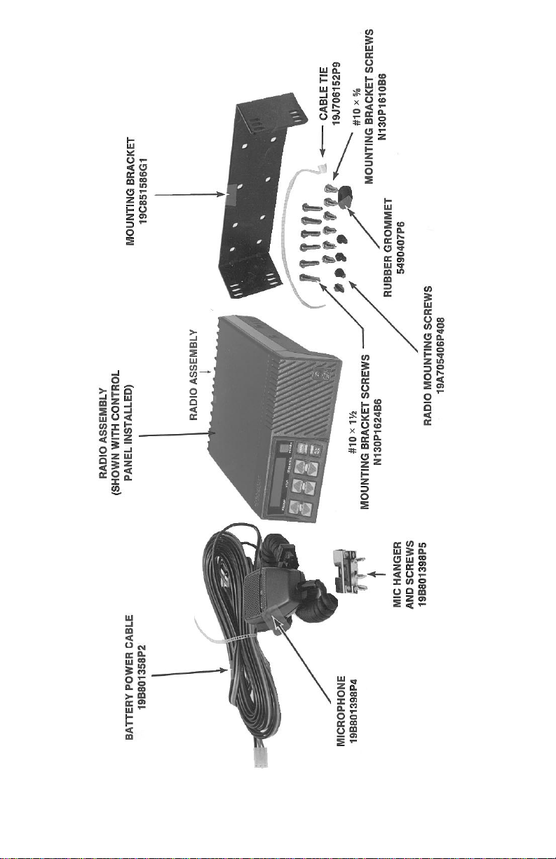
Figure 1 - Radio Components and Mounting Hardware
5
Page 6

1. Insta ll the Option Ca bl e CC3N (CC 08) in the ra di o.
2. Fasten the relay in the desired location, close to the voltage source,
using one #8 x 3/4 inch self-tapping screw.
3. Crimp an insulated 1/4 inch spade tab receptacle to one end of the
#18 re d wi re. Conne ct t he re ce ptac le to re lay lug #86. Cut the red lea d
so the fuse assembly is close to the voltage source. Install the fuse
holder . Att ach the other en d of the fuse l ead to t he volt age source with
appropriat e har dwa re . See Figur e 14.
4. Insert the b lack wi re with the Mol ex term inal into pin 13 of the optio n
connecto r housing suppli ed with the optio n cable. Plug t he connec tor
into the option cable .
5. Crim p insu late d 1/4 in ch sp ade tab rece pt acl e to the oth er end of the
black wire. Connect the re c e pta c le to rel a y lug #85.
6. Conne ct the horn or light circuit to lugs # 30 and #87 (not 87a) using
the insulate d 1/4 inch spa de tab rec ep tac le s.
EXTERNAL ALARM ON/OFF SWITCH OPTION SU1F
(SU02) (19C851585P7)
The External Ala rm Switch, when used wi th External Alarm Relay Option
SU01, allows the alarm rela y to be di sable d. Con nect the switc h in seri es with
the bla c k wire fr om th e re la y. Insert t he wire wi th th e Mo l ex termi nal into pi n
13 of the option cable connector housing. Splice the other switch lead to the
black wi re from the relay. See Fi gure 14.
If External Alarm ON/OFF Switch Option SU1F (SU02) is
used in conjunc ti on wit h th is option, ref er to Exte rnal Alarm
ON/OFF Switch Option SU1F (SU02).
NOTE
The rela y cont act make/ bre ak cu rrent and vol tage rating i s 30
amps at 16 volts.
NOTE
19
Interference with Vehicular Electronics - Electronic fuel injection systems, electronic anti-skid braking systems, electronic
WARNING
cruise cont rol syst ems, et c., are typi cal of th e type s of elec troni c
devices which may be prone to malfunction due to the lack of
protec t ion from rad io fre que ncy energ y present when transmitting. If the vehicle c ont ains suc h e qui pm en t, consul t the dea le r
for the make of the vehicle and enlist his aid in determining if
such electr onic circ uits wil l perf orm normall y when th e radio is
tra ns m it ti ng.
The accom pa nying illustra t ion s should help you in your in sta ll a tion.
PLANNING THE INSTALLATION
Before starting, plan your installation carefully so that it will be:
Safe for th e op er at or a nd pa s sengers i n the ve hi cl e .
••
Safe to operat e withi n easy reac h of cont rol s an d mic roph one .
••
Protecte d from da mag e fr om wat er.
••
Easy for the serviceman to service.
••
••
••
••
Oriented to minimi ze re fec ti ons in LCD displ ay.
Neat
Out of the way of auto mec hanics.
EQUIPMENT REQUIRED
The equ ipm e nt required for install ing the radi o is:
Electric Drill
••
No. 31 (1/8-inch) drill for No. 8 screws
••
No. 27 (9/64-inch) drill fo r No. 10 screws
••
Phillips scre wdri ve r
••
Crimp too l for terminals and antenna co nne c tor.
••
No. 20 TORX
••
5/8-inc h punc h or hole sa w for rub be r grom m e t
••
®
driver or 1/4-inch HEX driver for mount in g ra dio
It is sugge sted tha t yo u ta ke adva nta ge of the expe rie nce o f o ne o f the man y
authorized General Electric Service Stations located throughout the United
States by having them install the equipment.
TORX® Trademark of CAMCAR Division, TEXTRON, Inc.
6
Page 7

INSTALLATION IN VEHICLES POWERED BY
LIQUEFIED (LP) GAS
Radio installations in vehicles powered by liquefied petroleum gas with
the LP-gas container in the trunk or other sealed-off space within the interior
of the vehicle must conform to the National Fire Protection Association
Standard NFPA 58 whic h requires that:
••
Space co nta ining radio e quipment sha ll be isolated by a seal from the
space containing the LP-gas container and its fitting.
••
Outside filling con ne ctio ns sha ll be used fo r the LP-ga s co ntai ne r.
••
The LP-gas container space shall be vented to the outside of the
vehicle.
Figure 2 - T y pica l Hump or Da sh Moun t
Be careful to avoid damag ing some vital part (fuel tank, transmission housing, etc.) of the vehicle when drilling mounting
holes. Always check to see how far the mounting screws will
exten d be low the mounting su r fa ce be for e insta l li ng.
CAUTION
Radio inst allations i n vehicles po wered by lique fied petrole um gas
must confor m to the follo wing requir em ent s.
7
WARNING
Page 8

RUNNING CABLES
UNIVERSAL TONE CABLE OPTION CC3P (CC09)
(19C851585P5)
The Universal Tone Cable option requires the use of Option Cable CC3N
(CC08). P1 of the Universal Tone Cable plugs into P2 of the Option Cable.
The Universal Tone Cable Option provides all option connections on P2 and
a 9-pin Winchester connector for connecting to external tone encoders or
decode rs. See Figure 12.
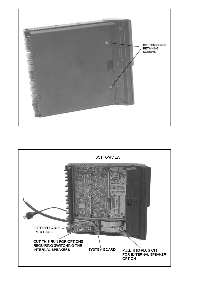
If the to ne decoder requires swi tching th e internal speaker , rem ove the radi o
bottom cover and c ut the PC run b etwe en hole s 6 and 7 on the System B oa rd.
Refer to Figur e 9 fo r PC run ide ntificat ion .
EXTERNAL SPEAKER OPTION LS1E (LS01)
(19C850550)
1. Mount the External Speaker where the sound will be directed to the
operator but not interfere with his vision or provide a hazard to
passengers in case of an accident. The speaker may be mounted on
the lower edge of the instrument panel, the firewall, or above the
windshield in some trucks. Use the mounting bracket as a template
for locating the mounting holes, and mount the speaker as shown in
Figure 13.
2. Insta ll the Option Ca bl e CC3N (CC 08) if not alre ad y prese nt.
3. Before replacing the bottom cover of the radio, unplug the internal
speaker from A5 J9 04 on the Syst em B oard. Refe r to Fig ure 9.
4. Pins are supplied on the ends of the speaker leads. Push these pins
into pins 2 and 9 of the connector housing supplied with the Option
Cable. Refer to Figure 11 .
Figure 12 - Tone Cable Pin L oca tion
17
To assure feasibility of the cable routing you plan to use, it is suggested
that you run the cabl es befo re mou nting the equipme nt. Be sure to leave some
slack in the cables going to the equipment so that the equipment may be pulled
out for servi cing with the power a ppl ied a nd a ntenn a att a ch ed .
heat (exhaust pipes, mufflers, tailpipes, etc.), battery acids, sharp edges or
mecha nical da mage , or wh ere th ey wi ll be a nuisa nce to autom obile m echanic s,
the driver or passengers. Keep wiring away from electronic computer modules, o ther el ectro nic m od ules and i gniti on c ircui ts to he lp p reve nt in terfe renc e
to these com po ne nts a nd radio equi pm ent.
the channels above and beneath the doors. You may also use the channel
through door and window columns, where they are convenient for running
cables, unless you plan to install rigid or flexible conduit in which to run the
cables.
Try to route the cables away from locations where they will be exposed to
In addition, try to utilize existing holes in the firewall and trunkwall and
POWER AND IGNITION CABLES
The Power Cable consists of a red lead, an orange lead, a black lead, a 3
pin systems plu g, and a set of fuses an d fuse holders t o be installe d (See Figure
3).
T o install the Power Cable, sta rt with the plug end of the cable at the locat ion
of the radio and run the three leads to the firewall, drill a 5/8 inch hole and
insert a rubber grom me t (cu stom er supp lied ).
To install the fuses: 1)Cut off 12 to 18 inches from the red and orange
wires; 2) Strip back the insulation approximately 3/8 of an inch on each end
of the wires; 3) Insert the stripped end of each wire into the small opening at
the end of each fuse holder section and crim p the wire to the fuse holder sec tion;
and 4) Place the fuse into the large section of the fuse holder and sna p the large
end of the fuse hold er to the sma ll end of the fuse hol de r.
Connect the orange fused lead to the positive (+) ba t tery terminal, and the
black to the negative (-) battery terminal. Always locate the fuse as close to
the battery as possible.
Connect the red lead to the ignition "on" sense point (preferably an
"Accessory" point on the fuse panel that is switched on when the ignition
switch is in the accessory position and in the "run" position). Locate the fuse
as close as possible to the accessory point.
8
Page 9

Figure 3 - Power Cable
9
Page 10

OPTIONAL ACCESSO RIES
AC POWER SU P P LY (12 V O LTS AT 13 AM P S)
OPTION PS1C (PS01) (19A704647P2) 12 1 Volts, 60 Hz
OPTION PS1D (PS0 2) (19 A7046 47P 3) 1 21/242 Volts,50/60 Hz
1. An empty connector housing and terminals are provided with the
power supply. Crimp three terminals on the end of the 9 foot power
cable provi ded wit h the rad io. An optio na l 20 foot cable is ava ila ble.
2. Insert the orange and red leads into pins 3, 6, or 9 of the connector
housing. Inse rt the blac k le ad into pins 1, 4, or 7. Figur e 10 p rovi de s
an illustra tion of the empt y conne ctor housing which plugs i nto J1 o f
the power supply .
DESK MICROPHONE OPTION MC1M (MC03)
(19B851086P10)
1. The desk microphone plugs into the microphone jack on the bottom
of the radio. Remove the standard microphone and reuse the same
cable clamp for strain relief.
2. If needed, adjust the microphone gain depending on the normal
talking distance from the microphone. Access the gain control
through the small ho le on the bott om of the microp hone base .
3. The microphone audio is nor mally switche d off when the PTT butto n
is released. If the mic ro phon e audi o nee ds to be ac ti ve at all tim es, a
jumper must be placed across the switch i nsid e the micr opho ne.
Figure 10 - Rear View of E mpty C onne c to r Housing
15
With some accessory points, the voltage only drops when the
ignition switch is in the START position. A connection point
should be used where the voltage is completely off when the
ignition switch is in the START posi tion.
NOTE
Certain problems may be encountered when accessory equipment is connected to the ignition or accesso ry lines of the vehicle,
wher e the se li nes m ay have l arge filte r cap acit ors or a leak age
path pr ese nt .
If the ra dio doe s not tu rn of f wit hin a r ea son ab le a mo unt of tim e
after the ignition is turned off, first try a different accessory or
ignition sense pick up point in the vehicle. Many vehicles have
more than one circ uit that is switche d by the ignition switch, and
one ma y be a vai la bl e tha t doe s n ot ha ve lar ge fil ter c ap aci tor s o r
a leakage path present.
If a different pi ckup point cannot be found, t hen add a 470-ohm
1-watt resistor from the ignition sense pickup point to ground.
This will disc harge the ca pacitor(s) o r reduce the leak age voltage
to a low value. Current drain through this resistor wil l be minimal
(less than 0.03A) whe n th e igni tion is swi tc he d on.
CAUTION
10
Page 11

Coil up the surplus cab les and secure them out of the way with the retai ning
strap provide d. Be sure t o l ea ve some sla ck in the cabl es going to the radio so
that it may be pul le d out for servicing with powe r ap pli e d.
INSTALLING THE RADIO
Mount the radio so that the controls are within reach of the operator. Use
the mount ing brac ket as a tem plat e to loca te the hole s, and moun t the ra dio as
shown in Figure 5. Be sure to leave enough room at the rear of the radio for
cable connections.
Figure 4 - Mounting Dim ensio n s
Figure 5 - Installing Mounting Bracket
11
Page 12

MICROPHONE CONNECTIONS
ANTENNA
Installatio n instructions for the antenn a are packaged with the ante nna. The
antenna must be installed in accordance with good engineering practices for
optimum results.
A pe rma ne nt mount type of antenna shoul d be locate d in the ce nte r of the
roof or rear deck. Glass mounted antenn as should be kept as high as possible
in the center of the rear window. Some states have laws restricting vision
obstruct ing items from the window. Be familiar with local laws be fore install-
ing glass mount antennas.
Try to route t he cab le away from loc ations where it will be exposed to he at,
sharp edges or mech an ic a l da m ag e, and w h er e i t will be out of the way of the
driver , passe nger s, or vehicl e mecha nics. Where ver possibl e, existi ng hole s in
the trunk wall, and the channe ls above or beneat h doors and window c olum ns
should be utilized.
A vo id routing th e anten na cabl e near a ny elec tronic modul es or along side
any vehicle wiring.
Conne ct the antenna ca ble to the TNC connector on the rad io.
Figure 7 - Microphone Bracket Mounting
In station applications, the radio may not operate properly with
the antenna mounted near the radio. Always mount the antenna
at least 5 feet from the radio.
13
Normally , the microphone is shipped conne cted to the microp hone jack on
the bottom of the radio. A cable clamp is used for strain relief and is attached
to the bottom of the rad io using a M4-0. 7x 8 Hex Hea d scre w.
Figure 6 - Micro phon e Conne c tion a nd Str ai n Reli e f
MICROPHONE BRACKET
Mount the magn etic mic rophone b racket whe re it wil l be wit hin easy reach
of the operator, but will not interfere with safe operation of the vehicle. Refer
to Figure 7 for bracket dimensions. The microphone must be placed in the
hanger so that the cord end of the mike housing is over th e magne t assem bl y.
T o m oun t the bra cke t, dri ll th re e No . 3 2 (1/ 8-inc h) pil ot holes, a nd use t he No.
8 x 5/8 screws supplied wit h the brac ke t.
12
NOTE
The magnetic hookswitch must be used with Channel Guard
applications.
Page 13

ANTENNA
Installatio n instructions for the antenn a are packaged with the ante nna. The
antenna must be installed in accordance with good engineering practices for
optimum results.
A pe rma ne nt mount type of antenna shoul d be locate d in the ce nte r of the
roof or rear deck. Glass mounted antenn as should be kept as high as possible
in the center of the rear window. Some states have laws restricting vision
obstruct ing items from the window. Be familiar with local laws be fore installing glass mount antennas.
Try to route t he cab le away from loc ations where it will be exposed to he at,
sharp edges or mech an ic a l da m ag e, and w h er e i t will be out of the way of the
driver , passe nger s, or vehicl e mecha nics. Where ver possibl e, existi ng hole s in
the trunk wall, and the channe ls above or beneat h doors and window c olum ns
should be utilized.
A vo id routing th e anten na cabl e near a ny elec tronic modul es or along side
any vehicle wiring.
Conne ct the antenna ca ble to the TNC connector on the rad io.
Figure 7 - Microphone Bracket Mounting
In station applications, the radio may not operate properly with
the antenna mounted near the radio. Always mount the antenna
at least 5 feet from the radio.
13
CAUTION
Page 14
Coil up the surplus cab les and secure them out of the way with the retai ning
strap provide d. Be sure t o l ea ve some sla ck in the cabl es going to the radio so
that it may be pul le d out for servicing with powe r ap pli e d.
INSTALLING THE RADIO
Mount the radio so that the controls are within reach of the operator. Use
the mount ing brac ket as a tem plat e to loca te the hole s, and moun t the ra dio as
shown in Figure 5. Be sure to leave enough room at the rear of the radio for
cable connections.
Figure 4 - Mounting Dim ensio n s
Figure 5 - Installing Mounting Bracket
11
Figure 8 - Bottom View
14
Figure 9 - Bottom View (Cover Removed)
Page 15

OPTIONAL ACCESSO RIES
AC POWER SU P P LY (12 V O LTS AT 13 AM P S)
OPTION PS1C (PS01) (19A704647P2) 12 1 Volts, 60 Hz
OPTION PS1D (PS0 2) (19 A7046 47P 3) 1 21/242 Volts,50/60 Hz
1. An empty connector housing and terminals are provided with the
power supply. Crimp three terminals on the end of the 9 foot power
cable provi ded wit h the rad io. An optio na l 20 foot cable is ava ila ble.
2. Insert the orange and red leads into pins 3, 6, or 9 of the connector
housing. Inse rt the blac k le ad into pins 1, 4, or 7. Figur e 10 p rovi de s
an illustra tion of the empt y conne ctor housing which plugs i nto J1 o f
the power supply .
DESK MICROPHONE OPTION MC1M (MC03)
(19B851086P10)
1. The desk microphone plugs into the microphone jack on the bottom
of the radio. Remove the standard microphone and reuse the same
cable clamp for strain relief.
2. If needed, adjust the microphone gain depending on the normal
talking distance from the microphone. Access the gain control
through the small ho le on the bott om of the microp hone base .
3. The microphone audio is nor mally switche d off when the PTT butto n
is released. If the mic ro phon e audi o nee ds to be ac ti ve at all tim es, a
jumper must be placed across the switch i nsid e the micr opho ne.
Figure 10 - Rear View of E mpty C onne c to r Housing
15
Page 16

OPTION CABLE OPTION CC3N (CC08) (19C85158P3)
9
The Option Cable brings all option connections from the System Board
through the back of the radio to the outside. This cable is required with all
external options. Supplied with the Option Cable is the empty connector
housing which p lugs int o P2 of the Opt ion Ca ble. Pins s uppl ied on the ends of
the wires of each opt ion (Molex #39-00-00 60) are in serted i nto this c onnecto r
housing. Refe r to the Int erco nnec tion Diag ram in t he back of this ma nual . See
Figure 1 1 for pin loc ati ons.
1. Remove the bottom cover of the radio by removing the two bottom
cover reta ining screws. Refe r to Figur e 8.
2. Remove the rubber plug from the slotted opening in the rear of the
radio adjacen t to the power cable .
3. Plug the Op ti on Cable into J905A on the System Board and push the
strain relief on the cable into the slotted opening. Refer to Figure 9.
4. Before replacing the bottom cover, check to see if the particular option
being added requires unplugging the internal speaker or changing a
jumper (Refer to t he sec ti on descri bin g the option).
16
Figure 11 - Option Cabl e Pin L oc at io ns
Page 17

UNIVERSAL TONE CABLE OPTION CC3P (CC09)
(19C851585P5)
The Universal Tone Cable option requires the use of Option Cable CC3N
(CC08). P1 of the Universal Tone Cable plugs into P2 of the Option Cable.
The Universal Tone Cable Option provides all option connections on P2 and
a 9-pin Winchester connector for connecting to external tone encoders or
decode rs. See Figure 12.
If the to ne decoder requires swi tching th e internal speaker , rem ove the radi o
bottom cover and c ut the PC run b etwe en hole s 6 and 7 on the System B oa rd.
Refer to Figur e 9 fo r PC run ide ntificat ion .
EXTERNAL SPEAKER OPTION LS1E (LS01)
(19C850550)
1. Mount the External Speaker where the sound will be directed to the
operator but not interfere with his vision or provide a hazard to
passengers in case of an accident. The speaker may be mounted on
the lower edge of the instrument panel, the firewall, or above the
windshield in some trucks. Use the mounting bracket as a template
for locating the mounting holes, and mount the speaker as shown in
Figure 13.
2. Insta ll the Option Ca bl e CC3N (CC 08) if not alre ad y prese nt.
3. Before replacing the bottom cover of the radio, unplug the internal
speaker from A5 J9 04 on the Syst em B oard. Refe r to Fig ure 9.
4. Pins are supplied on the ends of the speaker leads. Push these pins
into pins 2 and 9 of the connector housing supplied with the Option
Cable. Refer to Figure 11 .
Figure 12 - Tone Cable Pin L oca tion
17
Page 18

5. Plug the conne c to r int o P2 of t he Opti on Ca ble.
INSTALLATION IN VEHICLES POWERED BY
LIQUEFIED (LP) GAS
Radio installations in vehicles powered by liquefied petroleum gas with
the LP-gas container in the trunk or other sealed-off space within the interior
of the vehicle must conform to the National Fire Protection Association
Standard NFPA 58 whic h requires that:
••
Space co nta ining radio e quipment sha ll be isolated by a seal from the
space containing the LP-gas container and its fitting.
••
Outside filling con ne ctio ns sha ll be used fo r the LP-ga s co ntai ne r.
••
The LP-gas container space shall be vented to the outside of the
vehicle.
Figure 2 - T y pica l Hump or Da sh Moun t
Be careful to avoid damag ing some vital part (fuel tank, trans-
mission housing, etc.) of the vehicle when drilling mounting
holes. Always check to see how far the mounting screws will
exten d be low the mounting su r fa ce be for e insta l li ng.
Radio inst allations i n vehicles po wered by lique fied petrole um gas
must confor m to the follo wing requir em ent s.
7
SPEAKER MOUNTING BRACKET
Figure 13 - Mount ing the Spe ak er
EXTERNAL ALARM (HORN) RELAY OPT ION SU1C
(SUO1) (19A705499P1)
The Alarm Relay Option requires the the use of Option Cable CC3N
(CC08). Extern al Alarm ON/OFF Switch Opti on SU1F (SU02) is re quired t o
allow the horn relay to be disabled when desired. The Option consists of the
following items:
(1) Relay (19A149299P1)
(1) Fuse holder
(1) Fuse, 1 amp, 250 vol t
4 feet red wire , AWG #18 with Ring Tongue T er mi na l for 3/8 stu d
6 feet black wir e, AWG #18 with Molex #39-0 0-00 60 t e rm inal
(5) Insulated 1/4 inch spade tab rec ep tac les
(1) Ring Tongue Terminal for 3/8 inch stud
(1) #8 x 3/4 long Type A sheet m etal screw
(1) Nut Plate for #8 scre w
18
Page 19

1. Insta ll the Option Ca bl e CC3N (CC 08) in the ra di o.
2. Fasten the relay in the desired location, close to the voltage source,
using one #8 x 3/4 inch self-tapping screw.
3. Crimp an insulated 1/4 inch spade tab receptacle to one end of the
#18 re d wi re. Conne ct t he re ce ptac le to re lay lug #86. Cut the red lea d
so the fuse assembly is close to the voltage source. Install the fuse
holder . Att ach the other en d of the fuse l ead to t he volt age source with
appropriat e har dwa re . See Figur e 14.
4. Insert the b lack wi re with the Mol ex term inal into pin 13 of the optio n
connecto r housing suppli ed with the optio n cable. Plug t he connec tor
into the option cable .
5. Crim p insu late d 1/4 in ch sp ade tab rece pt acl e to the oth er end of the
black wire. Connect the re c e pta c le to rel a y lug #85.
6. Conne ct the horn or light circuit to lugs # 30 and #87 (not 87a) using
the insulate d 1/4 inch spa de tab rec ep tac le s.
EXTERNAL ALARM ON/OFF SWITCH OPTION SU1F
(SU02) (19C851585P7)
The External Ala rm Switch, when used wi th External Alarm Relay Option
SU01, allows the alarm rela y to be di sable d. Con nect the switc h in seri es with
the bla c k wire fr om th e re la y. Insert t he wire wi th th e Mo l ex termi nal into pi n
13 of the option cable connector housing. Splice the other switch lead to the
black wi re from the relay. See Fi gure 14.
If External Alarm ON/OFF Switch Option SU1F (SU02) is
used in conjunc ti on wit h th is option, ref er to Exte rnal Alarm
ON/OFF Switch Option SU1F (SU02).
NOTE
The rela y cont act make/ bre ak cu rrent and vol tage rating i s 30
amps at 16 volts.
NOTE
19
Page 20

Figure 14 - External Alarm Relay and ON/OFF Switch
5
20
Page 21

(19D901983 Sh 2 Rev.4)
INTERCONNECTION DIAGRAM
21
Page 22

OPTION INTERCONNECTION DIAGRAM
INTRODUCTION
This manual contains installation instructions for the TMX-8825 and
TMX-8810 Mobile Radio s and associate d acc essories. Include d are m ounting
instructions, for connecting the ignition cable a ssemblies and suggested c able
routings. Interconnection and wiring diagrams are contained in the back of
this manual.
UNPACKING AND CHECKING EQUIPMENT
Careful ly unpack the Two-Way Radio. It is recomme nded that you identify
the items ordered and check them off in the box below before discarding the
packing material. If any damage has occurred to the equipment during ship-
ment, file a claim with the carrier immediately.
STANDARD EQUIPMENT
T wo-Way Radio
Microphon e 19B801 398P4
Microphon e Hange r 19 B801 398P5
Battery Power Cable 19 B801 358P2
Mounting Hardware Kit 19A138051G11
OPTIONS
Option PD1A (PD01) - Noise Suppre ssio n Kit 19A148 539G1
Option PS1C (PS03) - AC Power Supply 1 21 Volt, 60 Hz, 13
Amp19A704647P2
Option PS1D (PS04) - AC Powe r Supply 121/24 2 Volt, 50/60 Hz ,
13Amp 19A704647P3
Option MC1M (MC05) - Desk Microphone 19B8510 86P10
Option CC3N (CC08) - Option Cable 19C851585P3
Option CC3P (CC09) - Universal Tone Cable (requi res Option
CC08) 19C851585P5
Option CC3R (CC10) - Power Cable (20 foot) 19B8013 58P4
3
22
(19D901983 Sh 3 Rev.3)
Page 23

NOTES
23
Page 24

Mobile Communications
TMX — 8825 (25W)
TMX — 8810 (10 W )
Installation Manual
Printed in U.S.A.
 Loading...