

Page 1
r
RX1290 Multi-Format Receive
Software Version 3.0.0 (and later)
REFERENCE GUIDE
EN/LZT 790 0003/2 R1A
Page 2

Preliminary Pages
ENGLISH (UK) - READ THIS FIRST!
If you do not understand the contents of this manual. DO NOT OPERATE
THIS EQUIPMENT. Also, translation into any EC official language of this
manual can be made available, at your cost.
ITALIANO - LEGGERE QUESTO AVVISO PER PRIMO!
Se non si capisce il contenuto del presente manuale. NON UTILIZZARE
L’APPARECCHIATURA.. È anche disponibile la versione italiana di questo
manuale, ma il costo è a carico dell’utente.
SVENSKA - LÄS DETTA FÖRST!
Om Ni inte förstår informationen i denna handbok. ARBETA DÅ INTE MED
DENNA UTRUSTNING. En översättning till detta språk av denna handbok
kan också anskaffas, på Er bekostnad.
PORTUGUÊS - LEIA O TEXTO ABAIXO ANTES DE MAIS NADA!
Se não compreende o texto deste manual. NÃO UTILIZE O
EQUIPAMENTO. O utilizador poderá também obter uma tradução do
manual para o português à própria custa.
FRANÇAIS - AVANT TOUT, LISEZ CE QUI SUIT!
Si vous ne comprenez pas les instructions contenues dans ce manuel. NE
FAITES PAS FONCTIONNER CET APPAREIL. En outre, nous pouvons
vous proposer, à vos frais, une version française de ce manuel.
DEUTSCH - LESEN SIE ZUERST DIESEN HINWEIS!
Sollte Ihnen der Inhalf dieses Handbuches nicht klar verständlich sein,
dann. BEDIENEN SIE DIESE GERÄTE NICHT! Eine Übersetzung des
Handbuches in diese Sprache ist gegen Berechnung lieferbar.
ESPAÑOL - LEA ESTE AVISO PRIMERO!
Si no entiende el contenido de este manual. NO OPERE ESTE EQUIPO.
Podemos asimismo suministrarle una traducción de este manual al (idioma)
previo pago de una cantidad adicional que deberá abonar usted mismo.
NEDERLANDS - LEES DIT EERST!
Als u de inhoud van deze handleiding niet begrijpt. STEL DEZE
APPARATUUR DAN NIET IN WERKING. U kunt tevens, op eigen kosten,
Jos et ymmärrä käsikirjan sisältöä. ÄLÄ KÄYTÄ LAITETTA. Käsikirja
Udstyret må ikke betjenes. MEDMINDRE DE TIL FULDE FORSTÅR
INDHOLDET AF DENNE HÅNDBOG. Vi kan også for Deres regning levere
Αν δεν καταλάβετε το περιεχόμενο αυτού του βοηθήματος/εγχειριδίου. ΜΗΝ
ΛΕΙΤΟΥΡΓΗΣΕΤΕ ΑΥΤΟΝ ΤΟΝ ΕΞΟΠΛΙΣΜΟ. Επίσης, αυτό το εγχειρίδιο
είναι διαθέσιμο σε μετάφραση σε αυτή τη γλώσσα και μπορείτε να το
een vertaling van deze handleiding krijgen.
SUOMI - LUE ENNEN KÄYTTÖÄ!
voidaan myös suomentaa asiakkaan kustannuksella.
DANSK - LÆS DETTE FØRST!
en dansk oversættelse af denne håndbog.
ΕΛΛΗΝΙΚΑ - ΔΙΑΒΑΣΤΕ ΠΡΩΤΑ ΑΥΤΟ!
αγοράσετε.
Copyright
© Copyright Ericsson AB 2011. All rights reserved.
Disclaimer
No part of this document may be reproduced in any form without the written permission of the
copyright owner.
The contents of this document are subject to revision without notice due to continued progress in
methodology, design and manufacturing. Ericsson shall have no liability for any error or damage of
any kind resulting from the use of this document.
ii
EN/LZT 790 0003/2 R1A 2011-06-06
Page 3

Preliminary Pages
Contents
Chapter 1: Introduction
This chapter identifies the equipment versions covered by this Reference Guide;
describes the purpose of the equipment in a typical system; provides a summary of
its main features; identifies the controls, indicators and connectors.
Chapter 2: Installing the Equipment
This chapter provides a guide to the suitability of an installation; gives detailed
procedures for the preparation, installation and configuration of the equipment
including important safety information; provides pin-out details of the external
connectors; and details the power-up/-down procedures.
Chapter 3: Operating the Equipment Locally
This chapter provides a guide to using the Front Panel LCD interface and details the
setting-up, configuration and operating procedures.
Chapter 4: Operating the Equipment Remotely
This chapter provides a guide to configuring and preparing the unit for remote
operation.
Chapter 5: Alarms
This chapter provides a guide to configuring the alarm interface.
Chapter 6: Options
This chapter describes the available hardware and software options for the
equipment.
Chapter 7: Preventive Maintenance and Fault-finding
This chapter details routine maintenance tasks to be performed; provides general
servicing advice, and information regarding warranty and maintenance; provides
general fault-finding information for other types of problem which may be
encountered.
Annex A: Glossary
Annex B: Technical Specification
Annex C: Menus
Annex D: Annex A: Glossary
Annex E: Factory Defaults
EN/LZT 790 0003/2 R1A 2011-06-06
iii
Page 4

Preliminary Pages
Introduction
This Reference Guide provides instructions and information for the installation and
operation of the RX1290 Multi-Format Receiver.
This Reference Guide should be kept in a safe place for reference for the life of the
equipment. It is not intended that this Reference Guide will be amended by the issue
of individual pages. Any revision will be by a complete reissue. Further copies of this
Reference Guide can be ordered from the address listed in Customer Services. If
passing the equipment to a third party, also pass the relevant documentation.
Revision History
Issues of this Reference Guide are listed below:
Issue Date Software Version Comments
1 Jul 2006 1.0.0 Initial release.
2 Oct 2006 1.0.0
3 Mar 2007 2.0.0 G.703 and IP Options added..
4 Jan 2008 3.0.0 Maintenance release.
5 May 2008 3.0.0 References to New IP Card added.
A June 2011 3.0.0
Updates to Annex B Technical Specification
Product name also corrected.
Allocation of Ericsson Number Identity and
re-brand completion.
Associated Documents
The following manuals/guides are also associated with this equipment:
Ericsson Document Identity Original Document
Number
1/1424-EN/LZT 790 0003 Uen A ST.US.E10228 RX1290 User Guide
Title
iv
1424-EN/LZT 790 0003 Uen A ST.TS.E10288 RX1290 RCP
Trademarks
All best endeavors have been made to acknowledge registered trademarks and
trademarks used throughout this Reference Guide. Any notified omissions will be
rectified in the next issue of this Reference Guide. Some trademarks may be
registered in some jurisdictions but not in others.
Registered trademarks and trademarks used are acknowledged below and marked
with their respective symbols. However, they are not marked within the text of this
Reference Guide.
EN/LZT 790 0003/2 R1A 2011-06-06
Page 5

Preliminary Pages
v
Registered Trademarks
®
Ethernet
Dolby
Registered trademark of Xerox Corporation.
®
/AC-3® Registered trademarks of Dolby Laboratories Licensing
Corporation.
Trademarks
Alteia
™
Trademark of Ericsson AB.
Macrovision
This product incorporates copyright protection technology that is protected by U.S.
patents and other intellectual property rights. Use of this copyright protection
technology must be authorized by Macrovision Corporation, and is intended for
home and other limited viewing uses only unless authorized by Macrovision.
Reverse engineering or disassembly is prohibited.
Warnings, Cautions and Notes
Heed Warnings
All warnings on the product and in the operating instructions should be adhered to.
The manufacturer cannot be held responsible for injuries or damage where warnings
and cautions have been ignored or taken lightly.
Read Instructions
All the safety and operating instructions should be read before this product is
operated.
Follow Instructions
All operating and use instructions should be followed.
Retain Instructions
The safety and operating instructions should be retained for future reference.
Warnings give information which, if strictly observed, will prevent personal injury or
death, or damage to property or the environment. They are highlighted for
emphasis, as in this example, and are placed immediately preceding the point at
which the reader requires them.
EN/LZT 790 0003/2 R1A 2011-06-06
Warning!
Page 6

Preliminary Pages
Caution!
Cautions give information which, if strictly followed, will prevent damage to
equipment or other goods. They are highlighted for emphasis, as in this example,
and are placed immediately preceding the point at which the reader requires them.
Note: Notes provide supplementary information. They are highlighted for
emphasis, as in this example, and are placed immediately after the relevant
text.
EMC Compliance
This equipment is certified to the EMC requirements detailed in Annex B, Technical
Specification. To maintain this certification, only use the leads supplied or if in doubt
contact Customer Services.
Contact Information
Support Services
Our primary objective is to provide first class customer care that is tailored to your
specific business and operational requirements. All levels are supported by one or
more service performance reviews to ensure the perfect partnership between
Ericsson and your business.
Warranty
All Ericsson products and systems are designed and built to the highest standards
and are covered under a comprehensive 12 month warranty.
Levels of Continuing Ericsson Service Support
For standalone equipment, then Ericsson BASIC Essential support is the value for
money choice for you. BASIC provides you with year-by-year Service long after the
warranty has expired.
Call Ericsson Sales for more details.
vi
EN/LZT 790 0003/2 R1A 2011-06-06
Page 7

Preliminary Pages
m
Customer Services
Europe, Middle East
and Africa
Americas Tel: +888 671 1268
China Tel: +86 10 8476 8676
Australia and New
Zealand
Internet Address
Tel: +44 (0) 23 8048 4455
Fax: +44 (0) 23 8048 4467
Email: tvsupportemea@ericsson.com
Tel: +678 812 6255
Fax: +678 812 6262
Email: tvsupportamericas@ericsson.co
Email: tvsupport@ericsson.com
Fax: +86 10 8476 7741
Tel: +852 2590 2388
Fax: +852 2590 9550
Email: tvsupportapac@ericsson.com
Tel: +612 (0) 9111 4027
Fax: +612 (0) 9111 4949
Email: tvsupportanz@ericsson.com
www.ericsson.com
US and Canada
International
Compression
Software Support Centre
Beijing
Beijing
Hong Kong
Hong Kong
Technical Training
Ericsson provides a wide range of training courses on the operation and
maintenance of our products and on their supporting technologies. Ericsson can
provide both regularly scheduled courses and training tailored to individual needs.
Courses can be run either at your premises or at one of our dedicated training
facilities.
International Tel: +44 (0) 23 8048 4229
Fax: +44 (0) 23 8048 4161
Email: tvglobaltraining@ericsson.com
Customer Services and Technical Training Postal Address
Ericsson
Unit 2
Strategic Park
Comines Way
Hedge End
Southampton
Hampshire
SO30 4DA
United Kingdom
EN/LZT 790 0003/2 R1A 2011-06-06
vii
Page 8

Preliminary Pages
Return of Equipment
If you need to return equipment for repair please contact your local Ericsson
Customer Services Department.
Please refer to the Customer Services Contact Information on Page vii
You will then be directed to return the faulty equipment to a repair centre with
the appropriate facilities for that equipment. A tracking number will be issued that
should be used if you need to enquire about the progress of the repair. The
equipment should be properly packed and the tracking number should be clearly
marked on the outside of the packaging
.
Technical Publications
If you need to contact Ericsson Technical Publications regarding this publication,
e-mail: tvtechpubs@ericsson.com.
viii
EN/LZT 790 0003/2 R1A 2011-06-06
Page 9

1 Introduction
Chapter 1
Contents
1.1 Scope of This Reference Guide ........................................................... 1-3
1.1.1 Who Should Use This Reference Guide............................................... 1-3
1.1.2 What Equipment is Covered by This Reference Guide ........................ 1-3
1.1.2.1 The Equipment Models......................................................................... 1-3
1.1.2.2 Software Version .................................................................................. 1-5
1.2 Summary of Features ........................................................................... 1-5
1.2.1 Main Features....................................................................................... 1-5
1.2.2 Inputs.................................................................................................... 1-7
1.2.2.1 ASI Input (Decoder).............................................................................. 1-7
1.2.2.2 Remote Control ....................................................................................1-7
1.2.2.3 DVB-S / DVB-S2 L-Band Inputs (Satellite Receivers) (Option) ............ 1-7
1.2.2.4 TTV G.703 DS3 and E3 Input (Telco Receivers) (Option)....................1-7
1.2.2.5 IP Input (Telco Receivers) (Option) ......................................................1-7
1.2.2.6 Frame Synchronization......................................................................... 1-7
1.2.3 Outputs .................................................................................................1-7
1.2.3.1 Transport Stream Outputs ....................................................................1-7
1.2.3.2 Video Outputs....................................................................................... 1-7
1.2.3.3 Audio Outputs....................................................................................... 1-7
1.2.3.4 Data Output .......................................................................................... 1-8
1.2.3.5 Alarm Output ........................................................................................1-8
1.3 The Satellite Receiver .......................................................................... 1-8
1.3.1 Typical Satellite System .......................................................................1-8
1.3.2 Input Connections................................................................................. 1-9
1.3.3 What the Satellite Receiver Does......................................................... 1-9
1.4 The Telco Receiver/Decoder..............................................................1-10
1.4.1 Typical Decoder System..................................................................... 1-10
1.4.2 What the Decoder Does ..................................................................... 1-10
1.5 Control Modes ....................................................................................1-11
1.5.1 Introduction......................................................................................... 1-11
1.5.2 Front Panel (Local) Modes ................................................................. 1-11
1.6 Guided Tour........................................................................................ 1-12
1.6.1 Construction .......................................................................................1-12
1.6.2 Front Panel Controls........................................................................... 1-12
1.6.3 Front Panel LEDs ............................................................................... 1-12
1.6.4 Rear Panel.......................................................................................... 1-13
EN/LZT 790 0003/2 R1A
1-1
Page 10

Introduction
List of Figures
Figure 1.1
Front View of a RX1290 Multi-Format Receiver................................... 1-3
Figure 1.2 Typical Satellite Compression System................................................. 1-8
Figure 1.3 What the Satellite Receiver Does......................................................... 1-9
Figure 1.4 Typical Compression System............................................................. 1-10
Figure 1.5 Role of the Decoder ........................................................................... 1-11
Figure 1.6 Front Panel States ............................................................................. 1-11
Figure 1.7 Front Panel Controls .......................................................................... 1-12
List of Tables
Table 1.1
Equipment Model Descriptions............................................................. 1-3
Table 1.2 Hardware Options ................................................................................ 1-4
Table 1.3 Software Options.................................................................................. 1-4
1-2
EN/LZT 790 0003/2 R1A
Page 11
Introduction
1.1 Scope of This Reference Guide
1.1.1 Who Should Use This Reference Guide
This Reference Guide is written for operators/users of the RX1290 Multi-Format
Receiver. It describes the unit’s functions and operation. The Reference Guide is
written to assist in the installation and day-to-day care and operation of the unit.
Maintenance information requiring the covers to be removed is not included.
Warning!
Do not remove the covers of this equipment. Hazardous voltages are present within
this equipment and may be exposed if the covers are removed. Only Ericsson
television trained and approved service engineers are permitted to service this
equipment.
Caution!
Unauthorized maintenance or the use of non-approved replacements may affect the
equipment specification and invalidate any warranties.
1.1.2 What Equipment is Covered by This Reference Guide
1.1.2.1 The Equipment Models
Ericsson is introducing an improved ordering system for its television products. New
part numbers are being introduced to support this new system. The tables below
shows the new part numbers used for ordering and supply of the product and its
options. The Multi-Format Receiver described in this Reference Guide is the base
model.
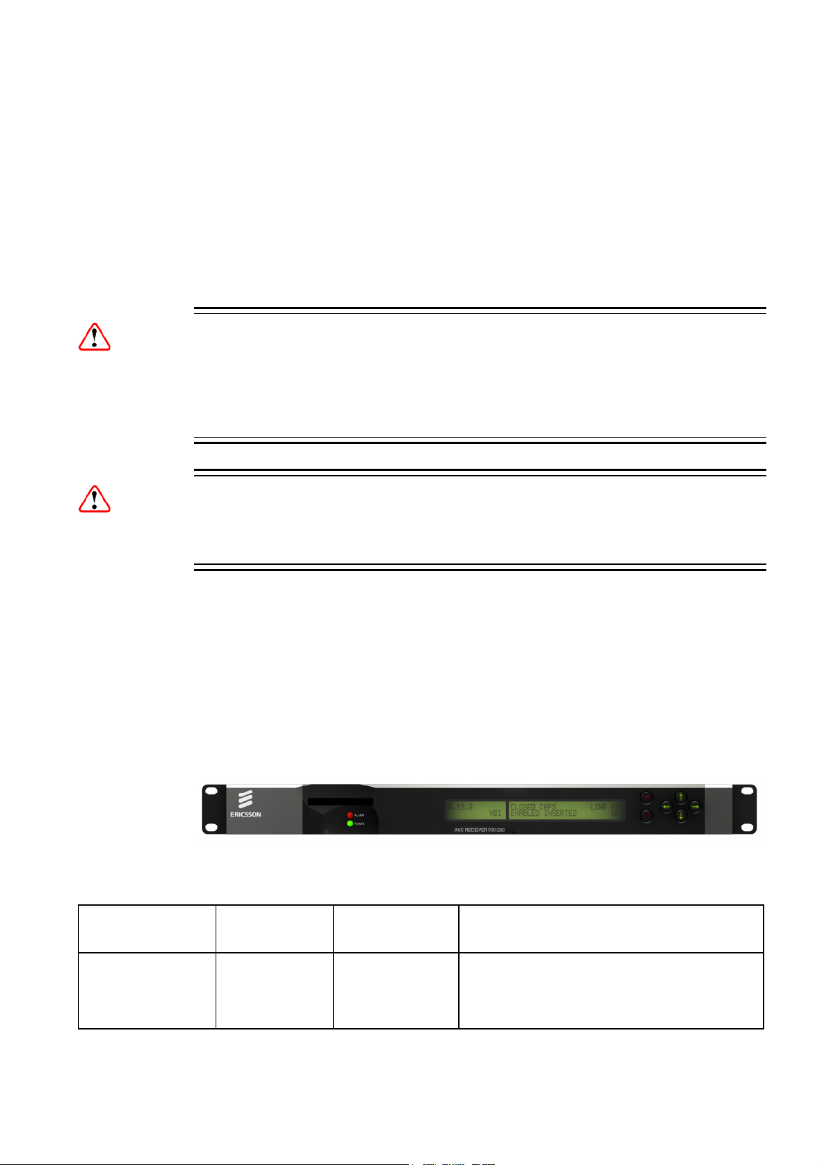
Figure 1.1 Front View of a RX1290 Multi-Format Receiver
Table 1.1 Equipment Model Descriptions
Marketing Code Price Object
Number
RX1290/BAS FAZ 101 0116/1 KDU 137 642/1
EN/LZT 790 0003/2 R1A
Supply Object
Number
Description
Decoder with integrated Common Interface
CAM reader, AC voltage input. SD MPEG-2
4:2:0, SD MPEG-2 4:2:2, HD MPEG-2 4:2:0
video decode only.
1-3
Page 12

Introduction
Table 1.2 Hardware Options
Marketing Code Price Object
Number
RX1290/HWO/DVBS2 FAZ 101 0116/3 ROA 128 3800
Supply Object
Number
Description
DVBS2 I/P SAT DEMOD
OPTION
RX1290/HWO/DVBS2/IF/C FAZ 101 0116/5 ROA 128 3801
DVBS2 I/P SAT
DEMOD+CONST O/P
RX1290/HWO/IP/PROFEC FAZ 101 0116/8 ROA 128 3802
IP, PRO-MPEG INPUT
OPTION
RX1290/HWO/G703 FAZ 101 0116/6 ROA 128 3803 G.703 INPUT OPTION CARD
RX1290/HWO/IP/GIGE FAZ 101 0116/7 ROA 128 3804
100/1000 BASE-T INPUT
OPTION
Table 1.3 Software Options
Marketing Code Price Object
Number
RX1290/SWO/MPEG2/HD/422 FAZ 101 0116/22 FAT 102 0205 MPEG-2 HD 4:2:2 LICENSE
RX1290/SWO/MPEG4/SD FAZ 101 0116/24 FAT 102 0206 MPEG-4 SD 4:2:0 LICENSE
RX1290/SWO/MPEG4/HD FAZ 101 0116/23 FAT 102 0207 MPEG-4 HD 4:2:0 LICENSE
Supply Object
Number
Description
RX1290/SWO/DIR5 FAZ 101 0116/14 FAT 102 0208 DIRECTOR V5 LICENSE
RX1290/SWO/AC3 FAZ 101 0116/11 FAT 102 0209 DOLBY AC3 LICENSE
RX1290/SWO/DVBS2/QPSK FAZ 101 0116/18 FAT 102 0210 DVB-S2 QPSK LICENSE
RX1290/SWO/DVBS2/8PSK FAZ 101 0116/16 FAT 102 0211 DVB-S2 8PSK LICENSE
RX1290/SWO/DVBS2/LSYM FAZ 101 0116/17 FAT 102 0212
DVB-S2 LOW SYMBOL RATE
LICENSE
RX1290/SWO/DVBS2/16APSK FAZ 101 0116/15 FAT 102 0213 DVB-S2 16APSK LICENSE
RX1290/SWO/CI FAZ 101 0116/12 FAT 102 0214
COMMON INTERFACE
LICENSE
RX1290/SWO/RAS FAZ 101 0116/28 FAT 102 0215 RAS LICENSE
RX1290/SWO/PROV/LOCK FAZ 101 0116/26 FAT 102 0216 PROVIDER LOCK LICENSE
RX1290/SWO/IP/PROMPEG FAZ 101 0116/20 FAT 102 0217 PRO-MPEG IP LICENSE
RX1290/SWO/UPCONV FAZ 101 0116/29 FAT 102 0218 UPCONVERSION LICENSE
RX1290/SWO/DCONV FAZ 101 0116/13 FAT 102 0219
DOWN CONVERSION
LICENSE
RX1290/SWO/AAC FAZ 101 0116/10 FAT 102 0220 AAC AUDIO LICENSE
RX1290/SWO/PW FAZ 101 0116/27 FAT 102 0222
1-4
EN/LZT 790 0003/2 R1A
PASSWORD PROTECTION
LICENSE
Page 13

Introduction
Marketing Code Price Object
Number
RX1290/SWO/LDELAY FAZ 101 0116/21 FAT 102 0223
Supply Object
Number
Description
LOW LATENCY DECODE
MODE (4:2:0 ONLY)
RX1290/SWO/HSETHER FAZ 101 0116/19 FAT 102 0224
HIGH SPEED DATA PIPING
LICENSE
RX1290/SWO/PAA FAZ 101 0116/25 FAT 102 0229
QUAD PHASE ALIGNED
MPEG-1 LAYER 2 AUDIO
RX1290/SWO/4AUD FAZ 101 0116/9 FAT 102 0221
DIGITAL AUDIO 3&4
LICENSE
RX1290/SWO/EBU/3.6.2 FAZ 101 0116/34 FAT 102 0227 RX1290 SW 3.6.2 FOR EBU
RX1290/SWO/UPG/MP4SD/MP4H FAZ 101 0116/31 FAT 102 0225
UPGRADE FROM MPEG4 SD
TO HD
RX1290/SWO/UPG/MP2422/MP4H FAZ 101 0116/30 FAT 102 0226
UPGRADE FROM MPEG-2
HD 4:2:2 TO MPEG-4 HD
1.1.2.2
Software Version
This Reference Guide covers the functions of software version 3.0.0 and later.
To verify the installed version access the Systems Menu (Menu 7.2.1). The menus
are described in Annex C, Menus.
1.2 Summary of Features
1.2.1 Main Features
The Multi-Format Receiver is fully compliant with the appropriate sections of the
MPEG-2
features:
• Front Panel Controls and Indications:
• Service Selection:
1
, DVB-S2 and MPEG-4 AVC3 specifications and offers the following
- A vertical split two line x 40 character back-lit dot matrix LCD display with
pushbuttons for Up, Down, Left, Right, Edit, and Save to provide information
and operator choice entry.
- LEDs to indicate lock and general alarm conditions.
- Chosen from a menu list of available Services carried in the currently
received Transport Stream.
1
Moving Pictures Expert Group: MPEG-2 specification ISO 13818.
2
European Digital Video Broadcasting (DVB) Project. EN 300 421 Digital broadcasting systems for television, sound and data services:
Framing structure, channel coding and modulation for the 11/12 GHz satellite service.
3
ITU-T Recommendation and ISO/IEC 14496-10 (MPEG-4 AVC) Advanced Video Coding.
EN/LZT 790 0003/2 R1A
1-5
Page 14

Introduction
- Up to 40 preselected choices can be stored within the unit.
• Multiple Inputs (Satellite Receivers):
- L-band Satellite Receivers have four inputs.
• Video Decoding:
- MPEG 4:2:0 mode support.
- MPEG 4:2:2 mode support (MPEG-2 Only).
• Audio Decoding:
- Sampling rate 48 kHz.
- All MPEG-1 data rates.
- AAC decode.
- All Dolby Digital AC-3 data rates, decoded as a Dolby Stereo downmix.
- Dolby E pass-through.
- Linear uncompressed audio, data rates as defined by SMPTE 302M.
- DTS audio detection and pass-through.
• Data:
- Low Speed Data: RS-232 asynchronous (up to 38.4 kbps).
- High Speed Data: Ethernet Data-piping (up to 5 Mbps) (option).
• Transport Stream Output:
- ASI Transport Stream output with maximum data rate 160 Mbps.
• Remote Control:
- SNMP.
- RS-232 (Alteia protocol).
• Clock/Calendar:
- Available to coordinate universal and local time.
- Constantly updated when locked to a valid Transport Stream.
• Transport Stream Demultiplexing:
- Maximum capability is 160 Mbps, depending on CA in use and input frontend.
• Video Decoding:
- Maximum Video decoding capability of 90 Mbps.
• Audio:
- Audio embedding in the digital video output.
1-6
• VANC data support:
- Closed Captions.
- VITC.
- ARIB reference spec TR23.
• Frame Synchronization of video output to a composite analogue input.
• Local Control Methods:
EN/LZT 790 0003/2 R1A
Page 15

Introduction
- Front Panel User Interface.
1.2.2 Inputs
1.2.2.1
1.2.2.2
1.2.2.3
1.2.2.4
1.2.2.5
1.2.2.6
ASI Input (Decoder)
One BNC connector supporting both byte-mode and single packet burst mode.
Remote Control
An RJ-45 Ethernet connector for connection to a PC or network switch to provide
SNMP control.
DVB-S / DVB-S2 L-Band Inputs (Satellite Receivers) (Option)
Four F-type connectors connect the L-band output of a suitable LNB either directly
or via a suitable attenuator giving lightning and surge protection.
TTV G.703 DS3 and E3 Input (Telco Receivers) (Option)
Equipped with a single BNC connector for receiving signals over a PDH Telco
network.
IP Input (Telco Receivers) (Option)
A single 10/100/1000BaseT RJ-45 connector for receiving signals over Ethernet
Frame Synchronization
A BNC connector accepts a composite video input to which the video output timing
can be synchronized.
1.2.3 Outputs
1.2.3.1
1.2.3.2
1.2.3.3
Transport Stream Outputs
• Up to three BNC connectors output ASI Transport Streams with a maximum
data rate of 160 Mbps, depending on the CA in use and the input card front-end.
Video Outputs
• One SVGA HD video output carried on a D-type connector for monitoring only.
• Three digital video outputs carried on BNC connectors (same connectors as
ASI).
• One SD Analogue composite video output on BNC.
Audio Outputs
• Two 9-way, D-type, male connectors each provide simultaneous analogue
stereo and balanced digital audio output. The digital mode can be changed via
the user interface.
EN/LZT 790 0003/2 R1A
1-7
Page 16
Introduction
• Four BNC connectors providing unbalanced audio output.
Data Output 1.2.3.4
• RS-232 asynchronous low-speed data output carried on a 9-way, D-type, female
connector.
• RJ-45 high speed data over Ethernet output (option).
1.2.3.5
Alarm Output
A 9-way, D-type connector for interfacing to the alarm and failure monitoring within
the Multi-Format Receiver. This includes a summary alarm signal that coincides with
the general front-panel ALARM LED.
There is one relay for failure monitoring. The operator can define (using the Alarm
Menu pages) which alarm conditions drive the relay. This is described in Chapter 5,
Alarms and Annex C, Menus.
1.3 The Satellite Receiver
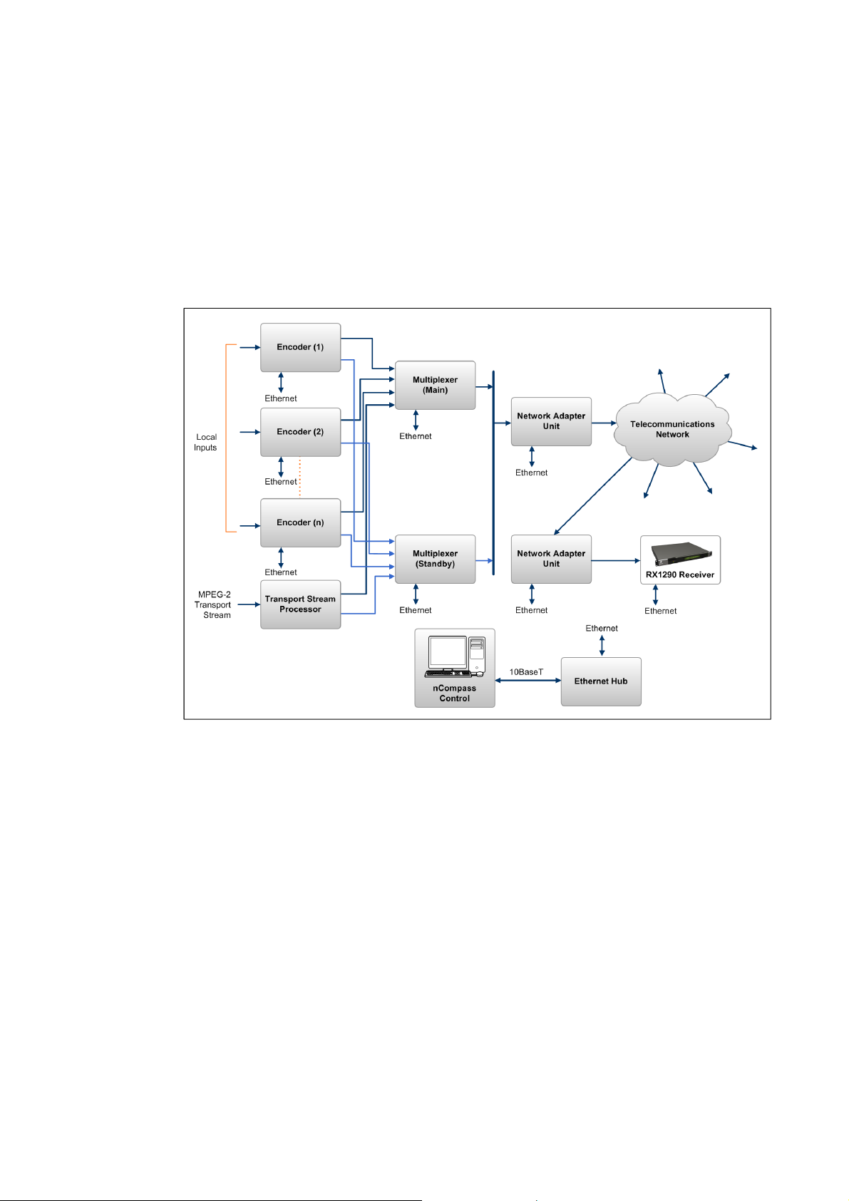
1.3.1 Typical Satellite System
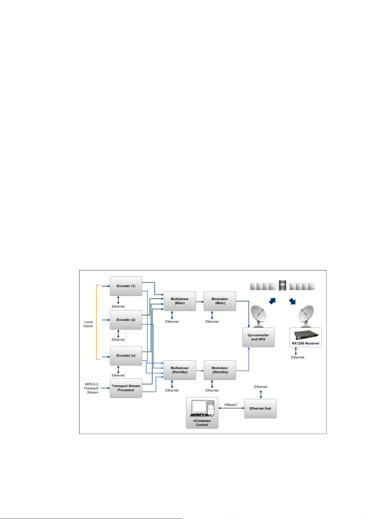
The Multi-Format Receiver is a component of the MPEG-4 AVC/MPEG-2/DVB
compliant range of Ericsson's equipment. They are designed for use by
broadcasters and distributors of video, audio and data Services over satellite.
1-8
Figure 1.2 Typical Satellite Compression System
EN/LZT 790 0003/2 R1A
Page 17
Introduction
1.3.2 Input Connections
The Satellite Receiver interfaces directly to Low-Noise Block (LNB) and accepts an
intermediate frequency (IF) input in the band 950 - 2150 MHz (L-band) for operation
in the specified symbol-rate range (see Annex B, Technical Specification). The unit
can provide dc power and polarization switching to the LNB.
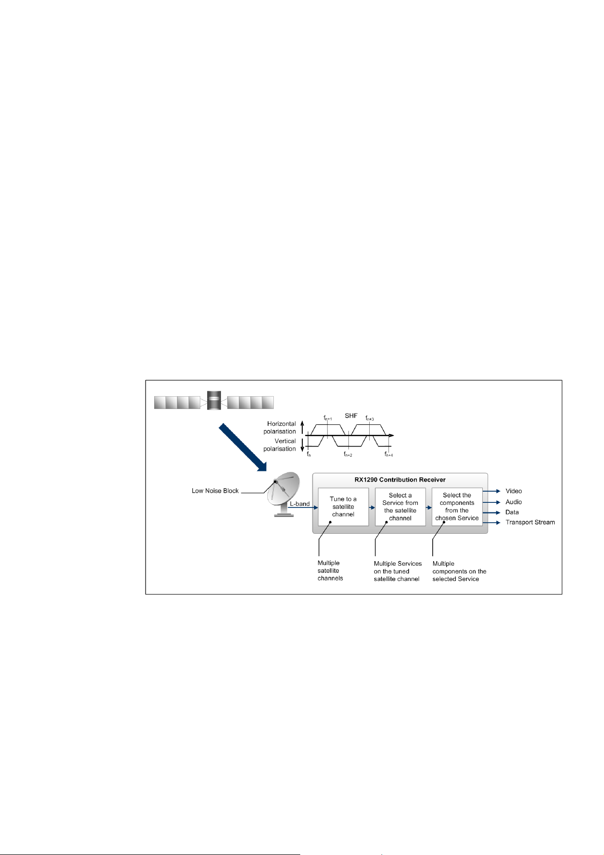
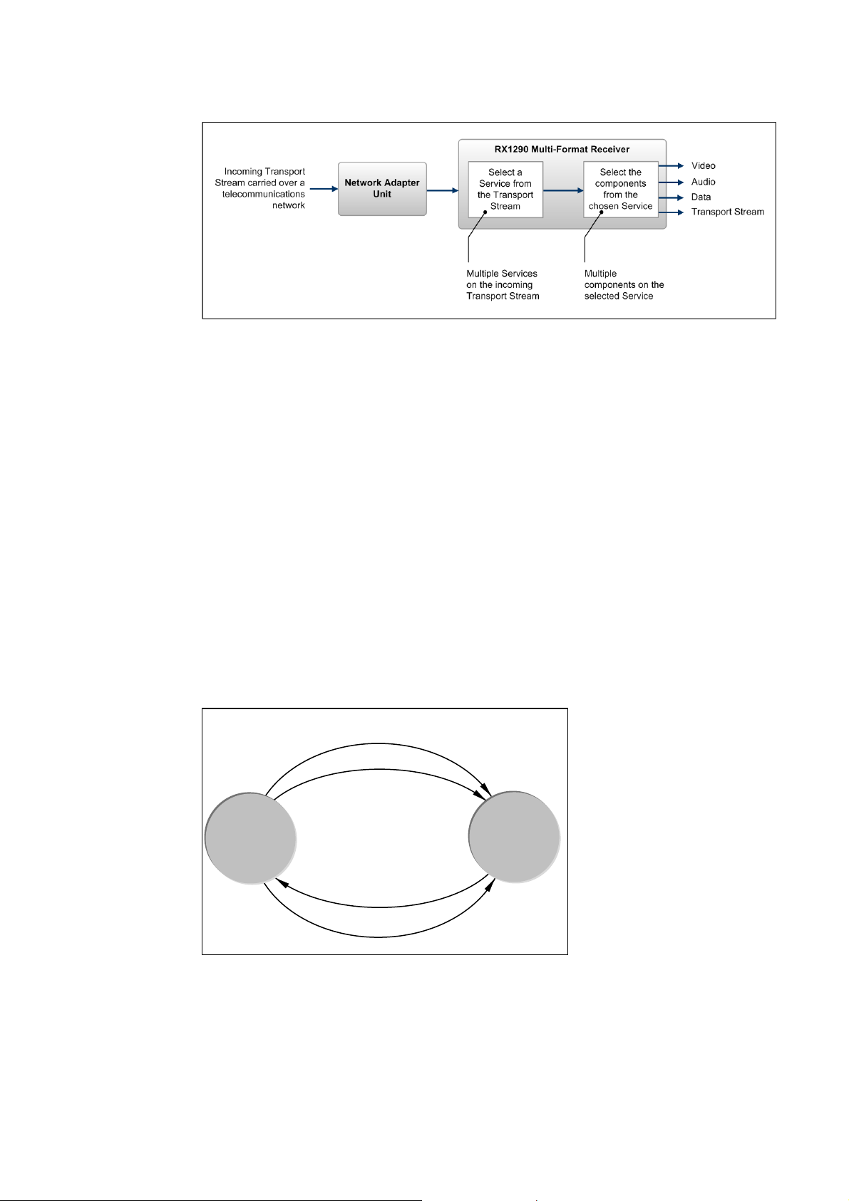
1.3.3 What the Satellite Receiver Does
The Receiver can be tuned to a specified satellite channel frequency and
polarization. The input is down-converted via a Low-Noise Block (LNB) to provide an
L-band input to the Receiver. The front-end tuning is microprocessor controlled with
a frequency synthesized local oscillator. A software tuning and acquisition algorithm
resolves translation errors (mainly due to the LNB).
The signal is then passed to a demodulator that recovers the signal using softdecision decoding. The resulting stream is Reed-Solomon decoded and
descrambled to provide inputs to the Decoder circuit. The received channel may
contain multiple Services, therefore the Receiver’s demultiplexer is configured to
select a single video Service and other audio/data components and present them at
the output.
Figure 1.3 What the Satellite Receiver Does
EN/LZT 790 0003/2 R1A
1-9
Page 18
Introduction
1.4 The Telco Receiver/Decoder
1.4.1 Typical Decoder System
The Decoder is a component of Ericsson’s range of equipment. It is designed for
use by broadcasters and distributors of video and audio Services. It can be used as
a Transport Stream monitor or to decode signals received over a
telecommunications network.
Figure 1.4 Typical Compression System
1.4.2 What the Decoder Does
The ASI interface is used to present the Transport Stream in the format required by
the internal Decoder circuitry. At this point, the operation of the unit is the same as
the Satellite Receiver.
The Decoder can be used to receive an input signal from a Public Telecom Network
via a Network Adapter Unit (NAU). No error correction is supported at the input of
the unit so a level of Quality of Service should be negotiated with the Telecom
Network Provider.
The Decoder is configured to select a single video Service and other audio/data
components from the multiple Services on the incoming Transport Stream and
present them at the output.
1-10
EN/LZT 790 0003/2 R1A
Page 19
Introduction
Figure 1.5 Role of the Decoder
1.5 Control Modes
1.5.1 Introduction
The Multi-Format Receiver is designed for unattended operation. Once set-up, the
unit requires no further attention except to ensure the fans are working. There are
up to three control modes associated with the Receiver (dependent upon options
fitted). The unit remains in the chosen control mode until another mode is requested.
Note: Local (Front Panel) Control is the factory default if Director is not installed.
1.5.2 Front Panel (Local) Modes
Operating the Multi-Format Receiver from the Front Panel is via two main operating
modes: Navigate and Edit. See Section 3.3, Front Panel Operating Modes.
Timeout (5 minutes)
EDIT Off
EDIT
EDIT On
NAVIGATE
SAVE
Figure 1.6 Front Panel States
EN/LZT 790 0003/2 R1A
1-11
Page 20
Introduction
1.6 Guided Tour
1.6.1 Construction
The Multi-Format Receiver is constructed using a screened self-ventilated modular
system. All operational inputs and outputs are via rear-panel connectors. The unit
may be operated freestanding or mounted in a 19-inch rack.
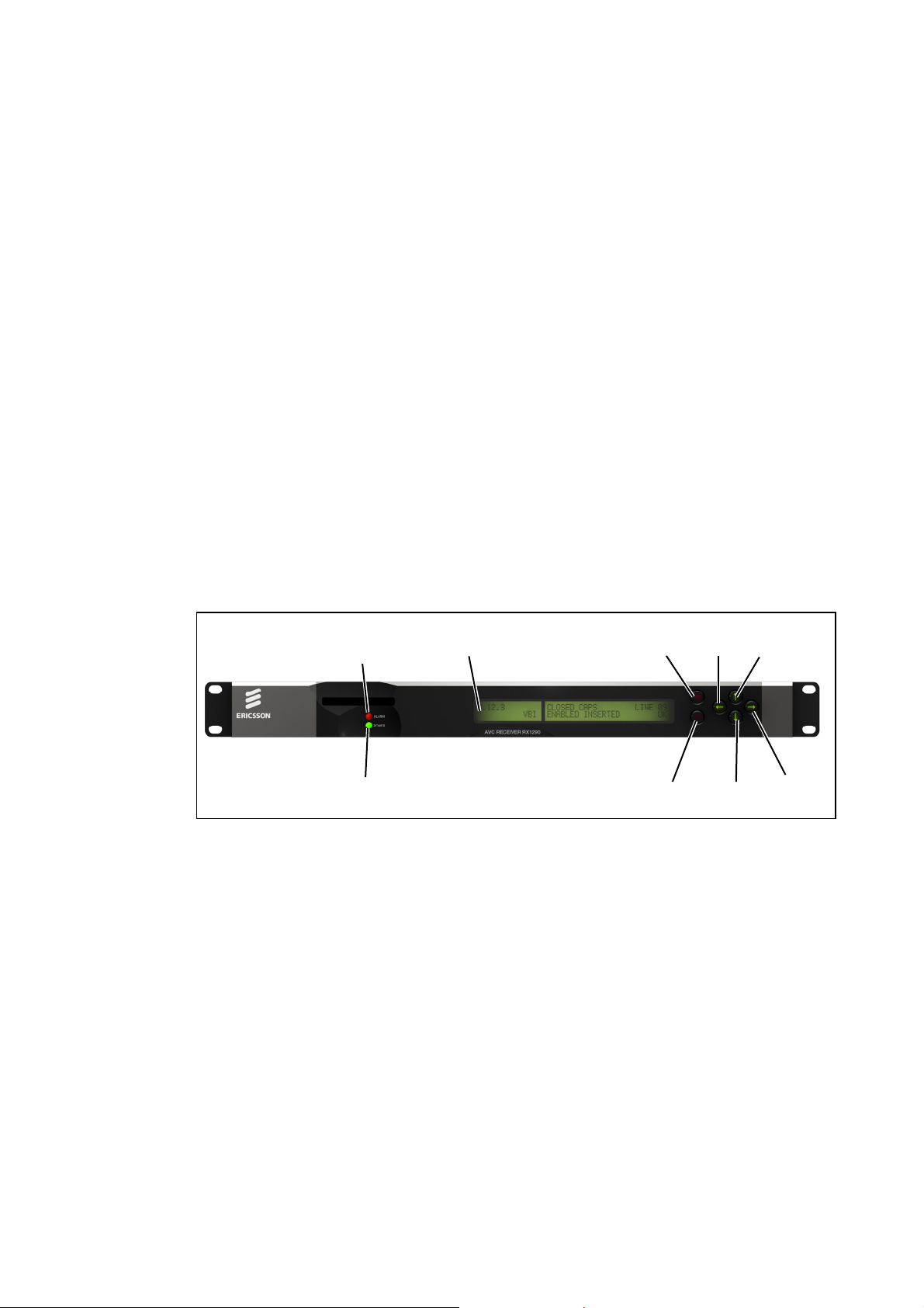
1.6.2 Front Panel Controls
The physical interface for the Front Panel consists of an alphanumeric LCD display,
pushbuttons, and status LEDs that are used to set-up and monitor the unit. The
general layout is shown in Figure 1.7. Information on the use of these controls is
given in Chapter 3, Operating the Equipment Locally.
User input is via six pushbuttons comprising four cursor pushbuttons: Left, Right,
Up, and Down; and two edit control pushbuttons: Edit and Save.
Each pushbutton has an integral green LED except Save, which has an integral red
LED. When lit these LEDs indicate to the user which pushbutton is currently active.
Automatic repeat following an initial delay period is implemented for the Left, Right,
Up, and Down pushbuttons in software.
ALARM LED
POWER LED
Figure 1.7 Front Panel Controls
1.6.3 Front Panel LEDs
Figure 1.7 shows the location of the LEDs on the front panel The LEDs indicate the
Multi-Format Receiver status as follows:
The red ALARM LED is used to indicate a Multi-Format Receiver fault condition,
e.g. a missing or faulty input signal. It should be off for correct operation, although it
may be lit briefly during power up.
LCD display
Edit Up
Save
Left
Down
Right
1-12
The green POWER LED is used to indicate that the Multi-Format Receiver is locked
to a Transport Stream when lit, indicates correct conditions and correct system
functioning.
EN/LZT 790 0003/2 R1A
Page 21

Introduction
1.6.4 Rear Panel
Inputs and outputs to the unit are taken via the rear panel. Connector descriptions
are given in Chapter 2, Installing the Equipment and Chapter 6, Options.
EN/LZT 790 0003/2 R1A
1-13
Page 22

Introduction
BLANK
1-14
EN/LZT 790 0003/2 R1A
Page 23

2 Installing the Equipment
Chapter 2
Contents
2.1 Read This First! ....................................................................................2-3
2.1.1 Handling ...............................................................................................2-3
2.1.2 Installing the Equipment ....................................................................... 2-3
2.1.3 Lifting ....................................................................................................2-3
2.1.4 Site Requirements ................................................................................2-3
2.1.4.1 Power Supplies..................................................................................... 2-3
2.1.4.2 Environment .........................................................................................2-3
2.1.4.3 Lightning Protection.............................................................................. 2-3
2.2 Preliminary Checks............................................................................... 2-4
2.2.1 Mechanical Inspection ..........................................................................2-4
2.2.2 Moving the Equipment Safely............................................................... 2-4
2.3 Installing the Equipment .......................................................................2-4
2.3.1 Fixing ....................................................................................................2-4
2.3.2 Ventilation............................................................................................. 2-5
2.3.3 Openings in the Covers ........................................................................2-5
2.3.3.1 Care in Positioning ...............................................................................2-5
2.3.3.2 Protection from Moisture ......................................................................2-5
2.3.4 Installing Cables - Safety...................................................................... 2-6
2.4 EMC Compliance Statements .............................................................. 2-6
2.4.1 EN 55022/AS/NZS 3548....................................................................... 2-6
2.4.2 FCC ...................................................................................................... 2-6
2.5 AC Supply Operating Voltage and Fusing – Safety Information........... 2-6
2.5.1 AC Power Supply .................................................................................2-6
2.5.2 AC Power Supply Cord........................................................................ 2-7
2.5.2.1 General................................................................................................. 2-7
2.5.2.2 Wire Colors........................................................................................... 2-7
2.5.3 Connecting the Equipment to the AC Power Supply ............................ 2-8
2.6 Protective Earth/Technical Earth .......................................................... 2-8
2.7 Signal Connections............................................................................... 2-9
2.7.1 General................................................................................................. 2-9
2.7.2 ASI/HD-SDI/SD-SDI OUT................................................................... 2-11
2.7.3 CVBS.................................................................................................. 2-11
2.7.4 Audio Outputs..................................................................................... 2-11
2.7.5 SVGA Output (RGB HV)..................................................................... 2-12
2.7.6 Frame Synchronization....................................................................... 2-13
2.7.7 Ethernet ..............................................................................................2-14
2.7.8 ASI IN ................................................................................................. 2-14
EN/LZT 790 0003/2 R1A
2-1
Page 24

Installing the Equipment
2.7.9 Alarm Connector and Relay ............................................................... 2-15
2.7.10 RS-232 Low-speed Asynchronous Data Output ................................ 2-15
2.7.11 Serial Remote Control........................................................................ 2-16
2.8 Option Card Connectors..................................................................... 2-16
List of Figures
Figure 2.1
Air-flow Through the Equipment........................................................... 2-5
Figure 2.2 AC Power Inlet Assembly..................................................................... 2-7
Figure 2.3 Location of the Technical Earth............................................................ 2-9
Figure 2.4 Typical Receiver Rear Panel................................................................ 2-9
Figure 2.5 Signal Connections ............................................................................ 2-10
List of Tables
Table 2.1
Supply Cord Wiring Colors................................................................... 2-7
Table 2.2 Non Standard Supply Cord Wire Colors............................................... 2-8
Table 2.3 Digital Output Connector.................................................................... 2-11
Table 2.4 Digital Output Connector.................................................................... 2-11
Table 2.5 Analogue/Digital Audio Connectors.................................................... 2-12
Table 2.6 Digital (Unbalanced) Audio Connectors ............................................. 2-12
Table 2.7 SVGA Connector................................................................................ 2-13
Table 2.8 Frame Sync Hi-Z Connector............................................................... 2-14
Table 2.9 Ethernet Pin-outs ............................................................................... 2-14
Table 2.10 Digital Input Connector....................................................................... 2-14
Table 2.11 Alarm Connector ................................................................................ 2-15
Table 2.12 RS-232 Low-speed Data.................................................................... 2-15
Table 2.13 RS232/RS485 Remote Control .......................................................... 2-16
2-2
EN/LZT 790 0003/2 R1A
Page 25

Installing the Equipment
2.1 Read This First!
2.1.1 Handling
The equipment must be handled and installed carefully and thoughtfully to prevent
safety hazards and damage.
2.1.2 Installing the Equipment
Ensure the personnel designated to fit the unit have the appropriate skills and
knowledge. If in any doubt, contact Ericsson Customer Services (see Preliminary
Pages for contact details).
Installation of the product should follow these instructions, and should only use
installation accessories recommended by the manufacturers. When rack mounted,
this equipment must have shelf supports as well as being fixed at the front panel.
Do not use this product as a support for any other equipment.
2.1.3 Lifting
In some circumstances the unit might be awkward to lift. In which case, do not
attempt to lift or move it without proper assistance or equipment. If in doubt, seek
assistance.
2.1.4 Site Requirements
2.1.4.1 Power Supplies
See Annex B Technical Specification for a full specification.
2.1.4.2 Environment
See Annex B, Technical Specification for a full specification.
Do not install this product in areas of high humidity or where there is danger of water
ingress.
2.1.4.3 Lightning Protection
Warning!
If the receiver has been subject to a lightning strike or power surge that has stopped
it working, disconnect the power immediately. Do not re-apply power until it has
been checked for safety. If in doubt contact Ericsson Customer Services.
EN/LZT 790 0003/2 R1A
2-3
Page 26

Installing the Equipment
Where appropriate, ensure this product has an adequate level of lightning
protection. Alternatively, during a lightning storm or when it is left unattended and
unused for long periods of time, unplug it from the supply outlet and disconnect the
output equipment. This prevents damage to the product due to lightning and power
line surges.
2.2 Preliminary Checks
2.2.1 Mechanical Inspection
Warning!
Removing the covers of this equipment may invalidate any warranties, cause a
safety hazard or/and affect the EMC performance.
2.2.2 Moving the Equipment Safely
Do not place this product on an unstable cart, stand, bracket, or
table. The product may fall, causing serious injury and serious
damage to the product. Use only with a cart, stand, bracket or
table recommended by Ericsson.
An appliance and cart combination should be moved with care. Quick stops,
excessive force, and uneven surfaces may cause the appliance and cart
combination to overturn. Do not move or carry the equipment whilst it is still
connected to the supply or other leads, is live, or is in operation.
2.3 Installing the Equipment
2.3.1 Fixing
The equipment is designed for fixed use only and has been shipped with fixing
brackets suitable for a standard 19-inch rack. When installed in a rack, it should be
secured using the fixing brackets. In addition, support shelves must be used to
reduce the weight on the brackets. Ensure it is firmly and safely located and it has
an adequate flow of free-air.
2-4
Slide the receiver onto the chassis supports and affix to the rack by means of an
M6 x 18 mm panhead screw in each corner.
A freestanding unit should be installed on a secure horizontal surface where it is
unlikely to be knocked or its connectors and leads disturbed.
EN/LZT 790 0003/2 R1A
Page 27
Installing the Equipment
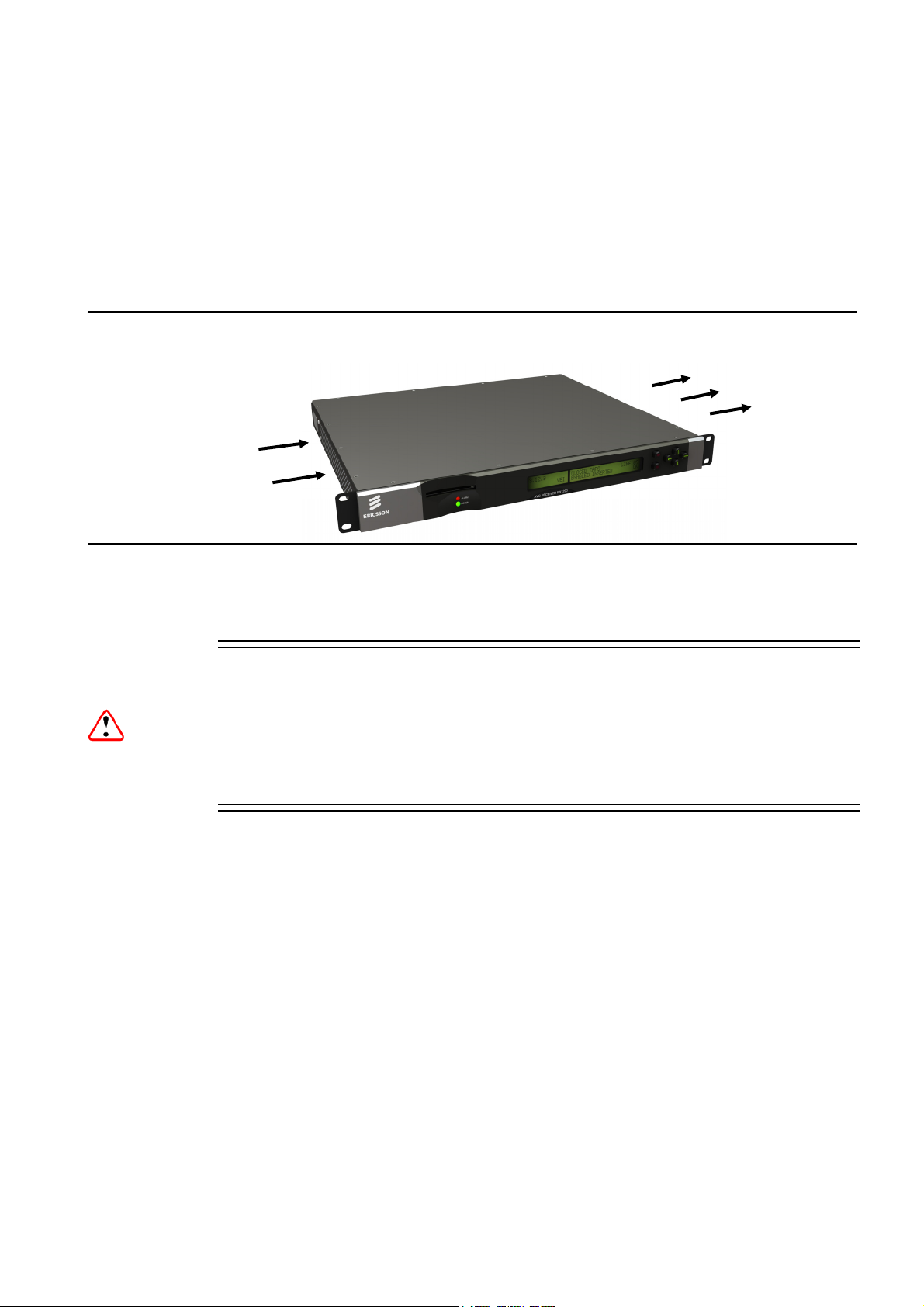
2.3.2 Ventilation
2.3.3 Openings in the Covers
Side openings in the unit, as well as side-mounted cooling fans, are provided for
ventilation. They ensure reliable operation of the product and protect it from
overheating. The openings of the fans must not be blocked or covered.
Fans are mounted on
this side of the unit
Figure 2.1 Air-flow Through the Equipment
2.3.3.1 Care in Positioning
The fans contained within this unit are not fitted with a dust/insect filter. Pay
attention to the environment in which it is to be used.
Do not install equipment so that the air intake of one aligns with the outlet on
another. Provide baffles and adequate spacing.
Air is released through
vents at this
side of the unit.
Cautions!
The equipment should never be placed near or over a radiator or other source of heat.
It should not be placed in a built-in installation such as a rack unless proper ventilation
is provided and the instructions have been adhered to.
Allow at least 40 mm free air-space at each side of the equipment to ensure
adequate cooling. Racks containing stacked equipment may need to be forced aircooled to reduce the ambient temperature within the rack.
2.3.3.2 Protection from Moisture
Do not install this equipment in areas of high humidity or where there is a danger of
water ingress.
EN/LZT 790 0003/2 R1A
2-5
Page 28

Installing the Equipment
2.3.4 Installing Cables - Safety
Power supply cables should be routed so that they are not likely to be walked on or
pinched by items placed upon or against them. Pay particular attention to cables at
plugs, convenience receptacles, and the point where they exit from the appliance.
Do not run AC power cables in the same duct as signal leads. Do not move or install
equipment whilst it is still attached to the mains supply. Ensure safety and ESD
precautions are observed whilst inter-connecting equipment.
2.4 EMC Compliance Statements1
2.4.1 EN 55022/AS/NZS 3548
This is a Class A product. In a domestic environment this product may cause radio
interference in which case the user may be required to take adequate measures.
2.4.2 FCC
This equipment has been tested and found to comply with the limits for a Class A
digital device, pursuant to Part 15 of the FCC Rules. These limits are designed to
provide reasonable protection against harmful interference when the equipment is
operated in a commercial environment.
This equipment generates, uses and can radiate radio frequency energy and, if not
installed and used in accordance with the Reference Guide, may cause harmful
interference to radio communications. Operation of this equipment in a residential
area is likely to cause harmful interference in which case the user will be required to
correct the interference at his/her own expense.
2.5 AC Supply Operating Voltage and Fusing – Safety Information
2.5.1 AC Power Supply
The equipment operates from an wide-ranging mains power supply (100-240 V AC
50/60 Hz nominal) and is designed for use in ambient air temperature in the range
0°C to +50°C. There are no links etc. to be altered for operation from different
supply voltages. The full Technical Specification is given in Annex B, Technical
Specification.
1
The EMC information was correct at the time of manufacture. The EMC tests were performed with the Technical Earth attached.
2-6
EN/LZT 790 0003/2 R1A
Page 29
Installing the Equipment
Warning!
The RX1290 should only be operated from the type of power source indicated on
the marking label. If you are not sure of the type to your business, consult your
appliance dealer or local power company. Do not overload wall outlets and
extension cords as this can result in a risk of fire or electric shock.
The RX1290 Receivers are not fitted with an AC power ON/OFF switch. Ensure the
supply socket outlet is installed or located near the equipment so that it is
accessible.
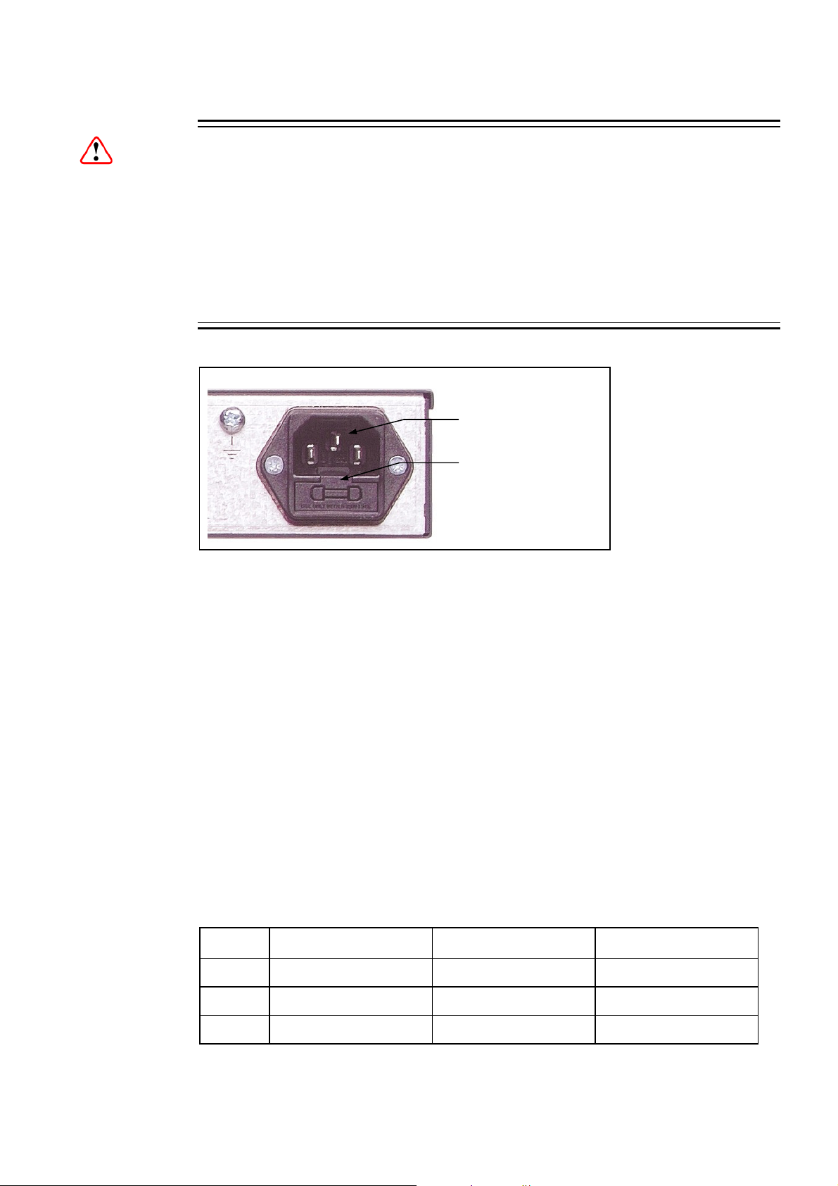
AC Power Inlet
Position of the fuse carrier
Figure 2.2 AC Power Inlet Assembly
Note: See Annex B, Technical Specification for fuse information.
2.5.2 AC Power Supply Cord
2.5.2.1 General
A two-meter power supply cord is supplied with this product. It is fitted with a molded
plug suitable for the USA, UK or mainland Europe as advised at the time of ordering.
Note: The equipment is not fitted with an AC power supply ON/OFF switch.
Ensure the socket-outlet supplying the equipment is installed near the
equipment so that it is easily accessible.
2.5.2.2 Wire Colors
The wires in the supply cord are colored as shown in Table 2.1.
Table 2.1 Supply Cord Wiring Colors
UK (BS 1363) EUROPE (CEE 7/7) USA (NEMA 5-15P)
Earth: Green-and-yellow Green-and-yellow Green
Neutral: Blue Blue White
Live: Brown Brown Black
EN/LZT 790 0003/2 R1A
2-7
Page 30

Installing the Equipment
If the colors do not correspond with the colored markings identifying the terminals in
a locally supplied plug, proceed as in Table 2.2. The inclusion of Table 2.2 is for
reference.
Table 2.2 Non Standard Supply Cord Wire Colors
Wire Color (UK) Action
green-and-yellow
blue
brown
...must be connected to the terminal in the plug which is marked
with the letter E or the safety earth symbol or colored green or
green-and-yellow.
...must be connected to the terminal in the plug which is marked
with the letter N or colored black.
...must be connected to the terminal in the plug which is marked
with the letter L or colored red.
2.5.3 Connecting the Equipment to the AC Power Supply
As there is no mains power switch fitted to this unit, ensure the local AC power
supply is switched OFF before connecting the supply cord.
Connect the mains lead to the equipment and then to the local supply.
2.6 Protective Earth/Technical Earth
Warning!
This unit must be correctly earthed through the molded plug supplied. If the local
mains supply does not have an earth conductor do not connect the unit. Contact
Ericsson Customer Services for advice.
2-8
Before connecting the unit to the supply, check the supply requirements in Annex B.
The terminal marked at the rear panel is a Technical Earth. Its use is
recommended. This is NOT a protective earth for electric shock protection. The
terminal is provided to:
• Ensure all equipment chassis fixed within a rack are at the same technical earth
potential. To do this, connect a wire between the Technical Earth terminal and a
suitable point on the rack.
• Eliminate the migration of stray charges when connecting between equipment.
The Technical Earth provides a suitable connection between the equipment and the
installation to give a low impedance path at normal operating frequencies.
EN/LZT 790 0003/2 R1A
Page 31

Installing the Equipment
Technical Earth
Figure 2.3 Location of the Technical Earth
2.7 Signal Connections
2.7.1 General
It is strongly recommended that the terminal marked at the rear panel of the
equipment is connected to a site Technical Earth before any external connections
are made and the equipment is powered. This limits the migration of stray charges.
All signal connections are made via the rear panel. A typical rear panel is shown in
Figure 2.4. The connections are also shown schematically in Figure 2.5, and a full
technical specification is given in Annex B. The Receiver provides a flexible
Transport Stream input interface. The status information appropriate to each input
type is available to the user via the User Interface, and also via the remote control
interfaces.
Caution!
AUD 1,2,3 & 4
ALARM
RELAY
TECHNICAL
EARTH
RGB HD
CVBS
FRAME
SYNC
AUDIO 1 & 2
10/100
Base T -
ASI/HD–SDI/SD–SDI
OUT x3
ASI IN
RS232/RS485
DATA
OUT
REMOTE
AC IN
Figure 2.4 Typical Receiver Rear Panel
EN/LZT 790 0003/2 R1A
2-9
Page 32

Installing the Equipment
RX1290 Multi-Format Receiver
Motherboard
RX1290/BAS
ASI In
Frame Synchronization
RS232/485
10 /100Base-T
Option Cards
ASI
FRAME SYNC
REMOTE CONTROL
ETHERNET
Constellation Output Satellite
(RX1290/HWO/DVBS/IF/CONST
PRO-MPEG FEC Input Card
(RX1290/HWO/IP/PROFEC
ASI/HDSDI/SDSDI OUT 1
ASI/HDSDI/SDSDI OUT 2
ASI/HDSDI/SDSDI OUT 3
AUDIO 1
AUDIO 2
CVBS OUT
DATA OUT
ALARM RELAY
AUD 1
AUD 2
AUD 3
AUD 4
RGB HD
DemodCard
Transport Stream/Digital Video Output
Transport Stream/Digital Video Output
Transport Stream/Digital Video Output
Analogue/Digital Audio Output
Analogue/Digital Audio Output
Analogue Video Output
Low-speed Async Data
Alarms
Digital Audio Output
Digital Audio Output
Digital Audio Output
Digital Audio Output
RGB HD Out
AC Power Supply
Figure 2.5 Signal Connections
2-10
EN/LZT 790 0003/2 R1A
G.703 E3/DS3 Input Card
(TT1290/HWO/G703)
Power Supply
Page 33

Installing the Equipment
2.7.2 ASI/HD-SDI/SD-SDI OUT
The unit has three ASI/SMPTE 292M video (HD-SDI)/656 video
(SD-SDI) outputs in the standard configuration.
ASI/HD-SDI/SD-SDI
The output standard must be selected from the user interface or
remote control interface.
The ASI/HD-SDI/SD-SDI output is coaxial via BNC connectors.
Video control is through the Video Menu (Menu 3.1).
Table 2.3 Digital Output Connector
Item Specification
Connector type BNC 75 Ω female socket
OUT 1/2/3
Connector designation
Pin-outs
Note: These sockets are under the control of Menu 5.1
2.7.3 CVBS
A BNC socket is provided for composite video output which
supports NTSC(M) (with and without pedestal) and
PAL(B,D,H,I,M).
Table 2.4 Digital Output Connector
Item Specification
Connector type BNC 75 Ω female socket
Connector designation
Centre
Shield
ASI/HD-SDI/SD-SDI OUT 1
ASI/HD-SDI/SD-SDI OUT 2
ASI/HD-SDI/SD-SDI OUT 3
Video output
Ground/Chassis
CVBS
ASI/HD-SDI/SD-SDI OUT 1
ASI/HD-SDI/SD-SDI OUT 2
ASI/HD-SDI/SD-SDI OUT 3
Pin-outs
Centre
Shield
Video output
Ground/Chassis
1
2.7.4 Audio Outputs
A pair of 9-way male D-type connectors provide two stereo
channels. Each connector carries a single channel of a stereo
pair in both analogue and balanced digital form.
Audio control is through the Service Menu (Menu 3).
EN/LZT 790 0003/2 R1A
6
AUDIO 1 / 2
5
9
2-11
Page 34

Installing the Equipment
In addition, four unbalanced digital audio outputs are available
via separate BNC connectors.
Table 2.5 Analogue/Digital Audio Connectors
Item Specification
Connector type 9-way, D-type, Male
Connector
designations
Pin-outs
Nominal output
impedance
Maximum data rate 3.072 Mbps
Analogue Output level
Load impedance
AUDIO 1
AUDIO 2
Pin 1 - Digital audio +
Pin 2 - Ground
Pin 3 - Left +
Pin 4 - Right +
Pin 5 - Ground
Pin 6 - Digital audio Pin 7 - Ground
Pin 8 - Left Pin 9 - Right -
50 Ω
+18 dBm nominal clipping level.
Selectable in range 12 to +24 dBm.
≥600 Ω balanced
AUD 1
Table 2.6 Digital (Unbalanced) Audio Connectors
Item Specification
Connector type
Connector designation AUD 1, AUD 2, AUD 3 and AUD 4
Pin-outs
Centre
Shield
BNC 75 Ω socket
Digital Audio output (AES/EBU)
Ground/Chassis
2.7.5 SVGA Output (RGB HV)
The EQUIPMENT is equipped with a SVGA 15-pin D-type
connector for video output monitoring in the standard
configuration.
The SVGA connector shall be set to RGB/HV (SVGA) or
YPrPb under control of the user interface and remote
control interfaces.
2-12
EN/LZT 790 0003/2 R1A
Page 35

Installing the Equipment
Table 2.7 SVGA Connector
Item Specification
Connector type 15-way D-type
Connector
Video Out
designation
Pin-outs 1 Red / Pr
2 Green / Y
3 Blue / Pb
75 Ω, 0,7Vt-t
75 Ω, 0,7Vt-t
75 Ω, 0,7Vt-t
4 NC
5 Video GND
6 Red GND
7 Green GND
8 Blue GND
9 NC
10 Sync GND
11 NC
12 NC
13 H-Sync
14 V-Sync
15 NC
2.7.6 Frame Synchronization
A BNC socket is used by the Decoder to frame lock to an
external video source (NTSC, PAL or SECAM). The frame
information is input as a composite signal, with or without active
video. The user can offset the synchronization to the video
output by ±8 lines of the reference signal, with a resolution of 1
pixel of the reference signal. Lip sync error introduced by the
Receiver is in the range -10 ms to +30 ms. This implies audio
frame skip and repeat may occur.
This Frame Sync is activated through the Service Menu
(Menu 3).
FRAME SYNC
EN/LZT 790 0003/2 R1A
2-13
Page 36

Installing the Equipment
Table 2.8 Frame Sync Hi-Z Connector
Item Specification
Connector type
Connector
designation
Pin: Centre Analogue Black and Burst Input
Shield Ground/Chassis
Impedance
2.7.7 Ethernet
The equipment has an Ethernet remote control port for SNMP
Control. This is also used for high speed data over Ethernet
output and engineering debug purposes.
Table 2.9 Ethernet Pin-outs
Item Specification
Connector type RJ-45 (100BaseT)
Connector
designation
BNC 75 Ω socket
FRAME SYNC
Last unit must be terminated with 75 Ω
10/100BaseT
10/100BaseT
1
8
Pin-outs
(Unused pins not
connected)
2.7.8 ASI IN
A BNC socket is provided for detection of the transport
stream lock on the ASI input.
Table 2.10 Digital Input Connector
Item Specification
Connector type BNC 75 Ω female socket
Connector
designation
Pin-outs
Centre
Shield
Pin 1 - Tx Out (+)
Pin 2 - Tx Out (-)
Pin 3 - Rx In (+)
Pin 6 - Rx In (-)
ASI IN
ASI IN
ASI Input
Ground/Chassis
2-14
EN/LZT 790 0003/2 R1A
Page 37

Installing the Equipment
2.7.9 Alarm Connector and Relay
The alarm relay connector has a summary relay. The
summary relay is activated whenever the unit detects an
alarm, or the power is switched off.
Table 2.11 Alarm Connector
Item Specification
Connector type
Connector
designation
Pin-outs Pin 1 - Open
9-way, D-type, Female for the summary alarm
relay
ALARM RELAY
Pin 2 - Open
Pin 3 - Open
Pin 4 - Relay 1, common pin
Pin 5 - Open
Pin 6 - Open
ALARM RELAY
1 5
6 9
Pin 7 - Open
Pin 8 - Relay 1, Normally Closed (Open on
Alarm)
Pin 9 - Relay 1, Normally Open (Closed on
Alarm)
2.7.10 RS-232 Low-speed Asynchronous Data Output
A 9-way, D-type female connector provides a asynchronous
low-speed data serial communications interface. The status
of the data output on this connector is given in the Data
Menus (Menus 3.4 and 3.5).
Table 2.12 RS-232 Low-speed Data
Item Specification
Connector type 9-way, D-type, Female
Connector
designation
Standards RS-232 DATA
RS-232 Data Out
1 5
6 9
DATA
Configuration DCE
Pin-outs
EN/LZT 790 0003/2 R1A
Pin 1 - Reserved
Pin 2 - Receive Data Output (RxD) (RS-232)
Pin 3 - Reserved
Pin 4 - No connection
2-15
Page 38

Installing the Equipment
Item Specification
Pin 5 - Ground (RS-232)
Pin 6 - Reserved
Pin 7 - No connection
Pin 8 - Reserved
Pin 9 - Reserved
2.7.11 Serial Remote Control
1
5
A 9-way, D-type male connector provides a configurable
RS232/RS485 asynchronous low-speed data serial
communications interface for remote control.
Table 2.13 RS232/RS485 Remote Control
Item Specification
Connector type 9-way, D-type, Female
Connector designation RS232/RS485 Remote
Standards RS-232/RS-485
Configuration
Pin-outs
RS-232 RS-485
Pin 1 - Data Carrier Detect (DCD) - Input
Pin 2 - Receive Data (RXD) - Input
Pin 3 - Transmit Data (TXD) - Output
Pin 4 - Data Terminal Ready - Output
Pin 5 - Ground
Pin 6 - Data Set Ready - Input
Pin 7 - Request to Send - Output
Pin 8 - Clear to Send - Input
Pin 9 - Not connected
Pin 1 - Not connected - Input
Pin 2 - Not connected - Input
Pin 3 - Not connected - Output
Pin 4 - Rx - Input
Pin 5 - Ground
Pin 6 - Not TX - Output
Pin 7 - TX - Output
Pin 8 - Not RX - Input
Pin 9 - Not connected
6
RS232/RS485 REMOTE
9
2.8 Option Card Connectors
Option cards are described in Chapter 6, Options.
2-16
EN/LZT 790 0003/2 R1A
Page 39

3 Operating the Equipment Locally
Chapter 3
Contents
3.1 Powering the Equipment ...................................................................... 3-5
3.1.1 Switching On ........................................................................................3-5
3.1.2 Power up Operating Modes.................................................................. 3-5
3.2 Front Panel Controls and Pushbuttons................................................. 3-6
3.3 Front Panel Operating Modes .............................................................. 3-6
3.3.1 General................................................................................................. 3-6
3.3.2 Navigate Mode .....................................................................................3-6
3.3.3 Edit Mode .............................................................................................3-7
3.4 Using the Local Controls ...................................................................... 3-7
3.4.1 LCD Menu Descriptions........................................................................ 3-7
3.4.2 Selecting a Menu Option ...................................................................... 3-8
3.4.3 Entering a Menu Value .........................................................................3-8
3.5 Setting Up Preset Services (Menu 1) ...................................................3-9
3.5.1 Using Preset Services .......................................................................... 3-9
3.5.2 Setting Up a Preset Service .................................................................3-9
3.6 Setting Up the Input (Menu 2) ............................................................ 3-10
3.6.1 DVB-S2 Satellite Receiver (TT1290/HWO/DVBS2 and
TT1290/HWO/DVBS2/IF/CONST)...................................................... 3-10
3.6.1.1 DVB-S2 Input Option Card TT1290/HWO/DVBS2/IF/CONST............ 3-11
3.6.2 Telco Receiver – RX1290/HWO/G703 ............................................... 3-11
3.6.3 10/100BaseT Input – RX1290/HWO/IP .............................................. 3-12
3.6.4 100/1000BaseT Dual IP Input – RX1290/HWO/GIGE........................ 3-13
3.7 Service Configuration (Menu 3) ..........................................................3-14
3.7.1 Selecting and Setting Up a Service ....................................................3-14
3.7.2 Selecting the Video Component .........................................................3-14
3.7.3 Setting Down Conversion Mode ......................................................... 3-15
3.7.4 Setting SD Monitor Aspect Ratio ........................................................3-15
3.7.5 Setting Video Delay ............................................................................3-16
3.7.6 Setting Video Output mode ................................................................3-16
3.7.7 Setting Low Delay Mode – RX1290/SWO/LDELAY ...........................3-16
3.7.8 Selecting the Audio Component .........................................................3-17
3.7.8.1 Introduction......................................................................................... 3-17
3.7.8.2 Selecting the Audio Manually ............................................................. 3-17
3.7.9 Setting Up Asynchronous Data (RS-232)........................................... 3-18
3.7.10 Setting Up High Speed Data Over Ethernet –
RX1290/SWO/HSETHER................................................................... 3-18
3.7.11 Setting Up Teletext .............................................................................3-19
EN/LZT 790 0003/2 R1A
3-1
Page 40

Operating the Equipment Locally
3.7.12 Setting Up VITC ................................................................................. 3-19
3.7.13 Setting Up Closed Captions ............................................................... 3-20
3.7.14 Setting Up ITS Insertion ..................................................................... 3-20
3.7.15 Setting Up VPS .................................................................................. 3-20
3.7.16 Setting Up WSS ................................................................................. 3-20
3.7.17 Setting Up Video Index....................................................................... 3-21
3.7.18 Setting Up Monochrome Samples...................................................... 3-21
3.7.19 Setting Up AMOL 1 and 2 .................................................................. 3-21
3.7.20 Setting Up NTSC Pedestal Insertion.................................................. 3-21
3.7.21 Setting Up VANC Data Insertion ........................................................ 3-22
3.7.22 Setting Up Splice Point Insertion........................................................ 3-22
3.7.23 Setting Up Station ID Insertion........................................................... 3-22
3.7.24 Setting Up AFD Insertion.................................................................... 3-22
3.7.25 Setting Up DVB Subtitles ................................................................... 3-23
3.7.26 Setting the PCR PID Menu................................................................. 3-23
3.7.27 Viewing the Network ID Menu............................................................ 3-23
3.8 Setting Up the Conditional Access/Scrambling (Menu 4)................... 3-23
3.8.1 Introduction ........................................................................................ 3-23
3.8.2 Basic Interoperable Scrambling System (BISS) (Menu 4.4) .............. 3-24
3.8.3 Remote Authorization System (RAS) (Menu 4.1)............................... 3-24
3.8.4 Director (Menu 4.3) ............................................................................ 3-24
3.8.5 DVB Common Interface (Menu 4.2)................................................... 3-24
3.9 Setting Up the Transport Stream Output (Menu 5) ............................ 3-25
3.9.1 Set-Up Procedure............................................................................... 3-25
3.9.2 Setting the Output Connector............................................................. 3-25
3.9.3 Transport Stream Output Bit-rates ..................................................... 3-26
3.9.4 Transport Stream Packet Lengths...................................................... 3-26
3.10 Setting Up the Alarms (Menu 6)......................................................... 3-26
3.11 Setting Up System Parameters (Menu 7)........................................... 3-27
3.12 Restarting the Unit.............................................................................. 3-28
List of Figures
Figure 3.1
Power up Operating Mode ................................................................... 3-5
Figure 3.2 Front Panel Controls and Pushbuttons ................................................ 3-6
List of Tables
Table 3.1
Navigate Mode ..................................................................................... 3-6
Table 3.2 Edit Mode ............................................................................................. 3-7
Table 3.3 Selecting a Menu Option...................................................................... 3-8
Table 3.4 Entering a Menu Value......................................................................... 3-8
Table 3.5 Setting Up a Preset Service ................................................................. 3-9
Table 3.6 Setting Up the DVB-S2 Satellite Receiver.......................................... 3-10
Table 3.7 Setting Up the TTV G.703 Interface................................................... 3-11
Table 3.8 Setting Up the IP Interface ................................................................. 3-12
Table 3.9 Setting Up the Dual IP Interface......................................................... 3-13
Table 3.10 Selecting a Service............................................................................. 3-14
Table 3.11 Selecting the Video Component......................................................... 3-14
Table 3.12 Setting Down Conversion................................................................... 3-15
3-2
EN/LZT 790 0003/2 R1A
Page 41

Table 3.13 Setting Aspect Ratio ...........................................................................3-16
Table 3.14 Setting Video Delay Mode .................................................................. 3-16
Table 3.15 Setting Video Ddelay Mode ................................................................ 3-16
Table 3.16 Setting Low delay mode .....................................................................3-17
Table 3.17 Manually Selecting the Audio Components........................................ 3-17
Table 3.18 Setting Up Async Data .......................................................................3-18
Table 3.19 Setting Up High speed Data over Ethernet ........................................3-18
Table 3.20 Setting Up Teletext ............................................................................. 3-19
Table 3.21 Setting Up VITC.................................................................................. 3-19
Table 3.22 Setting Up Closed Captions ...............................................................3-20
Table 3.23 Setting Up ITS Insertion .....................................................................3-20
Table 3.24 Setting Up VPS................................................................................... 3-20
Table 3.25 Setting Up WSS.................................................................................. 3-20
Table 3.26 Setting Up Video Index....................................................................... 3-21
Table 3.27 Setting Up Monochrome..................................................................... 3-21
Table 3.28 Setting Up AMOL 1 and 2................................................................... 3-21
Table 3.29 Setting Up NTSC Pedestal Insertion ..................................................3-21
Table 3.30 Setting Up VANC Data Insertion ........................................................3-22
Table 3.31 Setting Up Splice Point Insertion ........................................................3-22
Table 3.32 Setting Up Station ID Insertion ........................................................... 3-22
Table 3.33 Setting Up AFD Insertion.................................................................... 3-22
Table 3.34 Setting Up DVB Subtitles.................................................................... 3-23
Table 3.35 Viewing the PCR PID Menu ...............................................................3-23
Table 3.36 Viewing the Network ID Menu ............................................................3-23
Table 3.37 Setting Up the Transport Stream Output (TSO) .................................3-25
Table 3.38 Setting Up the Output Connector .......................................................3-25
Table 3.39 Maximum Descrambled Transport Stream Output Bit-rates............... 3-26
Table 3.40 Setting Up the Alarms......................................................................... 3-26
Table 3.41 Setting Up a System........................................................................... 3-27
Table 3.42 Viewing the Multi-Format Receiver Details Menu............................... 3-28
Table 3.43 System Restart Menu ......................................................................... 3-28
EN/LZT 790 0003/2 Rev R1A 2011-06-06
3-3
Page 42

Operating the Equipment Locally
BLANK
3-4
EN/LZT 790 0003/2 R1A
Page 43

Operating the Equipment Locally
3.1 Powering the Equipment
3.1.1 Switching On
Caution!
This equipment should not be operated unless the cooling fan is working and there
is free-air flow around the unit.
Connect the signal inputs and AC power supply to the Multi-Format Receiver and
power up the unit. After a short period of initialization and the Multi-Format Receiver
gaining lock, the unit powers up in Navigate mode. This is the usual operating
condition.
The POWER LED will be on (green) when a signal is locked and off when unlocked.
See Figure 3.2 for the location of the POWER LED.
3.1.2 Power up Operating Modes
Figure 3.1 Power up Operating Mode
EN/LZT 790 0003/2 R1A
3-5
Page 44

Operating the Equipment Locally
3.2 Front Panel Controls and Pushbuttons
Front Panel items are described under Section 1.6, Guided Tour.
ALARM LED
LCD display
POWER LED
Figure 3.2 Front Panel Controls and Pushbuttons
3.3 Front Panel Operating Modes
3.3.1 General
Operating the Multi-Format Receiver from the Front Panel is via two operating
modes: Navigate Mode (see Section 3.3.2) and Edit Mode (see Section 3.3.3).
Edit Up
Save
Left
Down
Right
3.3.2 Navigate Mode
Navigate mode allows the user to move between menus and pages within menus
(editing the left display area).
Table 3.1 Navigate Mode
Action Result
Up Pushbutton Pressed
Down Pushbutton Pressed
Left Pushbutton Pressed
Right Pushbutton Pressed
Edit Pushbutton Pressed
Save Pushbutton Pressed No effect.
Go to page given by uplink of current page, obtain and
display current data.
Go to page given by down link of current page, obtain and
display current data.
Go to page given by left link of current page, obtain and
display current data.
Go to page given by right link of current page, obtain and
display current data.
Enter Edit mode at current page (if permitted else no
effect).
3-6
EN/LZT 790 0003/2 R1A
Page 45

Operating the Equipment Locally
Pushbutton LEDs will be updated to indicate which pushbutton presses are still valid
as each navigation pushbutton press event is processed. For example, a lit Up
pushbutton LED indicates there are pages above the current one.
3.3.3 Edit Mode
Edit mode edits the right display area and allows the user to alter control
parameters that define the Multi-Format Receiver behavior. To enter Edit mode
press the Edit pushbutton when on a page containing an editable control parameter
and the front panel is the controlling user interface. Edit may be entered on some
special pages at all times, for example on the page defining the controlling user
interface.
The Front Panel returns to Navigate mode when Edit is pressed again (abort edit
with no save) or when Save is pressed (save modified parameter values).
Processing of events from the front panel event queue depends on the current
operating mode of the front panel.
Table 3.2 Edit Mode
Action Result
Up Pushbutton Pressed Increases value of current edit parameter by one unit.
Down Pushbutton
Pressed
Left Pushbutton Pressed
Right Pushbutton
Pressed
Edit Pushbutton Pressed
Save Pushbutton Pressed
Decreases value of current edit parameter by one unit.
Moves cursor one edit parameter/parameter digit left (making
that the current edit parameter).
Moves cursor one edit parameter/parameter digit right
(making that the current edit parameter).
Aborts edit (no save/action of any modified parameters) and
returns to Navigate mode, obtain and display current data.
Save/action new parameter values and returns to Navigate
mode, obtain and display current data.
Pushbutton LEDs are updated to indicate which pushbutton presses are still valid as
each edit pushbutton press event is processed. For example, when the Left
pushbutton LED is lit it indicates there are additional editable parameters to the left
of the current cursor position. There is a maximum idle period of five minutes when
Edit mode will time out and return to Navigate mode.
3.4 Using the Local Controls
3.4.1 LCD Menu Descriptions
Detailed LCD menu descriptions are given in Annex C, Menus. This chapter
concentrates on describing the use of the menus for local operation.
EN/LZT 790 0003/2 R1A
3-7
Page 46

Operating the Equipment Locally
3.4.2 Selecting a Menu Option
Some items shown in the right display area of the front panel LCD display have a
set number of options. An example of this is the VIDEO TEST PATTERN (Menu
3.1.6) which has a number of preset Video Test Patterns associated with it. Use the
following steps as a general guide to selecting an option.
Table 3.3 Selecting a Menu Option
Step Action Result
1
2 Press Edit on the front panel.
3
4
Select the menu and display the
required selection.
Use the arrow pushbuttons to
step through the options.
Press Save to store the option
or press Edit to cancel the
selection and return to the
source menu.
3.4.3 Entering a Menu Value
Some items shown in the right display area of the front panel LCD display have a
user-entered value. An example of this is the IP Address (Menu 7.1.3) in which the
unit’s Network address has to be entered. Use the following steps as a general
guide to entering a value.
Table 3.4 Entering a Menu Value
Normally there is only one selectable item. If
there is more than one, use the Right and Left
pushbuttons as described in Table 3.4.
The Save button will come on to show that the
new option can be stored.
This action scrolls through the options in a
continuous loop.
3-8
Step Action Result
1
2 Press Edit on the front panel.
3
4
5 Press Save to store the option.
EN/LZT 790 0003/2 R1A
Select the menu and display the
required selection.
Use the Right or Left
pushbutton to move the cursor
to the required digit.
Change the value by using the
arrow pushbuttons.
The Save button will come on to show that the
new value can be stored.
Each pushbutton has a built-in LED that turns
on if the pushbutton function is appropriate to
the displayed information.
Page 47

Operating the Equipment Locally
3.5 Setting Up Preset Services (Menu 1)
3.5.1 Using Preset Services
This group allows up to 40 Services to be stored as presets. Selecting a Service
from the preset list in Menu 1 automatically reconfigures the Multi-Format Receiver
to receive that Service with its associated parameters set as stored.
3.5.2 Setting Up a Preset Service
Follow the steps in Table 3.5 to store the current Service as a preset.
Table 3.5 Setting Up a Preset Service
Step Action Result
1
2
3
4 Press Save.
Use the menus to set-up the unit
so that the required Service is
current.
(Refer to Section 3.7, Service
Configuration (Menu 3)).
Go to Menu 1 to view the Preset
menu.
Select a location to store the
preset. The Edit mode cannot
be entered unless a valid
Service being decoded.
This selects the Service and associated
parameters for the preset process.
This displays the menu which allows the
Current Service to be stored at a chosen
location (01 – 40). If there is no Current
Service, the menu display reads NO STORED
SERVICE.
Use Edit and the arrow pushbuttons to step
through the stored items. This allows a specific
location to be chosen. Any vacant locations
are marked by NO STORED SERVICE.
This stores the current Service and its
associated parameters as a preset in the
selected location. This adds the Service to the
list displayed on page 1.
EN/LZT 790 0003/2 R1A
3-9
Page 48

Operating the Equipment Locally
3.6 Setting Up the Input (Menu 2)
3.6.1 DVB-S2 Satellite Receiver (TT1290/HWO/DVBS2 and TT1290/HWO/DVBS2/IF/CONST)
Table 3.6 Setting Up the DVB-S2 Satellite Receiver
Step Action Result
1
2
3
4
5
6
7
Go to Menu 2.3 and select
SOURCE 1.
Scroll to Menu 2.3.2. Enter the
LNB FREQUENCY then press
Save.
Scroll to Menu 2.3.2.1. Enter
the SATELLITE FREQUENCY
then press Save.
Scroll to Menu 2.3.2.2. Enter
the SYMBOL RATE then press
Save.
Scroll to Menu 2.3.2.3. Enter
the DVB Modulation Standard
then press Save.
Scroll to Menu 2.3.2.4. Enter
the
ROLL-OFF then press Save.
Scroll to Menu 2.3.2.5. Enter
the SEARCH RANGE then
press Save.
The Receiver can take its signals from four
sources. Set-up source 1.
This sets up the LNB frequency for the
selected Source in MHz.
This sets up the Satellite frequency for the
selected Source in MHz.
Sets the symbol rate for the selected Source in
Msymbols/s.
This sets up the DVB modulation Standard
(DVB-S or DVB-S2). FEC detection is
automatic. In DVB-S2 mode the demodulator
automatically detects and locks to both QPSK
and 8PSK constellations.
Sets the Roll-Off of the demodulator Root
Nyquist Filter. Choose between 35%, 25%,
20%. This value should match that set in the
transmitting modulator.
This sets up the centre frequency Search
Range for the selected Source in kHz.
3-10
8
Scroll to Menu 2.3.2.6. Enter
the LNB POWER and
VOLTAGE settings then press
Save.
Sets the LNB power for the selected Source
(ON, OFF, BOOSTED). BOOSTED provides
1V extra power over the ON setting. Also sets
the LNB voltage settings (18v – Horiz, 13v –
Vert).
9
Scroll to Menu 2.3.2.7. Enter
the LNB 22 kHz setting then
Enables or disables the LNB 22 kHz control
tone for the selected Source (On, Off).
press Save.
10
Repeat steps 2 through 9 for
input 2 to 4
EN/LZT 790 0003/2 R1A
Page 49

Operating the Equipment Locally
3.6.1.1 DVB-S2 Input Option Card TT1290/HWO/DVBS2/IF/CONST
The DVB-S2 demod option TT1290/HWO/DVBS2/IF/CONST offers three
L-band inputs plus an IF input. If this input option card is fitted in the receiver then
note that Menu 2.3.5 sets the IF input frequency. LNB Frequency, Satellite
Frequency and LNB Power parameters are not applicable for this input.
The DVB-S2 demod option TT1290/HWO/DVBS2/IF/CONST also offers a
constellation output in DVB-S2 mode. This output can be enabled for each Lband/IF input from the menu 2.3.X.6. Enabling this mode disables the demodulator
transport stream rendering the receiver unable to decode a service.
3.6.2 Telco Receiver – RX1290/HWO/G703
Table 3.7 steps through the set-up procedure of the Telco Receiver using
Menu 2 Input, and the TTV G.703 input.
Table 3.7 Setting Up the TTV G.703 Interface
Step Action Result
1
2
3
4
5
6
7
Connect the cable to the TTV
G.703 input.
Power up the unit and navigate
to Menu 2 Input.
Press the Right pushbutton to
access Menu 2.3.
Navigate to INTERLEAVER
(Menu 2.3.3), then press Edit.
Select Enable or Disable, then
press Save.
Navigate to SIGNAL LEVEL
(Menu 2.3.4), then press Edit.
Select Normal or Low, then
press Save.
Navigate to REED-SOLOMON
(Menu 2.3.2), then press Edit.
Select ENABLE, then press
Save.
Return to Input Menu 2, it should
display the current status. If
status is NOT LOCKED, verify
that the cable is properly
connected and that all values
have been entered correctly.
Accesses the Input menu.
Selects the G.703 menu.
Sets the required interleaving.
Sets the unit sensitivity to the input signal level.
Enables FEC functionality.
EN/LZT 790 0003/2 R1A
3-11
Page 50

Operating the Equipment Locally
3.6.3 10/100BaseT Input – RX1290/HWO/IP
Table 3.8 steps through the set-up procedure of the Telco Receiver using
Menu 2 Input, and the IP input.
Table 3.8 Setting Up the IP Interface
Step Action Result
1
2
3
4
5
6
Connect the Ethernet cable to
the IP input connector.
Power up the unit and
navigate to Menu 2 Input.
Navigate to UDP PORT (Menu
2.3.2), then press Edit.
Select the Receive UDP Port
number, then press Save.
Navigate to IP INPUT IP
ADDRESS (Menu 2.3.2.1),
then press Edit.
Select the IP address, then
press Save.
Navigate to IP INPUT
SUBNET MASK (Menu
2.3.2.2), then press Edit.
Select the Subnet mask, then
press Save.
Navigate to IP INPUT
GATEWAY ADDRESS (Menu
2.3.2.3), then press Edit.
Select the Gateway address,
then press Save.
Accesses the Input menu.
Edits the UDP Port parameter.
Edits the IP Input address parameter.
Edits the IP Input subnet mask parameter.
Edits the IP Input Gateway address parameter.
3-12
7
Navigate to IP INPUT
Edits the IP Input Multicast IP address parameter.
MULTICAST IP ADD (Menu
2.3.2.4), then press Edit.
Select the Multicast IP
address, then press Save.
8
Return to Input Menu 2, it
should display the current
status. If status is NOT
LOCKED, verify that the cable
is properly connected and that
all values have been entered
correctly.
EN/LZT 790 0003/2 R1A
Page 51

Operating the Equipment Locally
3.6.4 100/1000BaseT Dual IP Input – RX1290/HWO/GIGE
Steps through the set-up procedure of the Receiver using
Menu 2 Input, and the IP input.
Table 3.9 Setting Up the Dual IP Interface
Step Action Result
1
2
3
4
5
6
7
Connect the Ethernet cables to
the IP input connectors.
Power up the unit and navigate
to Menu 2 Input.
Navigate to NETWORK
INTERFACE 1
Navigate to IP ADDRESS, then
press Edit.
Select the IP address, then
press Save.
Navigate to NET MASK
ADDRESS, then press Edit.
Select the Subnet mask, then
press Save.
Navigate to GATEWAY
ADDRESS, then press Edit.
Select the Gateway address,
then press Save.
Navigate to NETWORK
INTERFACE 2 and repeat steps
4, 5 and 6
Accesses the Input menu.
Accesses parameters of Port 1
Edits the IP Input address parameter.
Edits the IP Input subnet mask parameter.
Edits the IP Input Gateway address parameter.
Accesses and edits parameters of Port 2
8
Navigate to LISTENING
Accesses parameters of listening multicast 1
STREAM 1
9
Navigate to MCAST IP, then
Edits the Listening IP address parameter.
press Edit.
Select the IP address, then
press Save.
10
Navigate to UDP PORT, then
Edits the Listening UDP port number parameter.
press Edit.
Select the UDP port number,
then press Save.
11
Navigate to LISTENING
STREAM 2 and repeat steps 9
Accesses and edits parameters of listening
multicast 2
and 10
EN/LZT 790 0003/2 R1A
3-13
Page 52

Operating the Equipment Locally
Step Action Result
12
Return to Input Menu 2, it
should display the current
status. If status is NOT
LOCKED, verify that the cable is
properly connected and that all
values have been entered
correctly.
3.7 Service Configuration (Menu 3)
3.7.1 Selecting and Setting Up a Service
Each Transport Stream may contain many Services. Menu 3 allows a Service to be
chosen as current and the profile of its components to be specified. This Service will
be used as the power up default Service until a new Service is selected.
Table 3.10 Selecting a Service
Step Action Result
1
Go to Menu 3 and select the
required Service.
The Edit mode cannot be
entered unless there are
available Services.
This page shows the total number of Services
available in the incoming Transport Stream. Use
Edit and the arrow pushbuttons to select the
required Service.
2 Press Save. This stores the Service as the Current Service.
3.7.2 Selecting the Video Component
Table 3.11 Selecting the Video Component
Step Action Result
1
2
Go to Menu 3.1 and press
Edit. Select one of the video
streams or enter a video
stream PID.
Scroll to Menu 3.1.6 and edit
the parameter for setting the
response to loss of video
(FREEZE FRAME, BLACK
FRAME, BLUE FRAME,
75% BARS AND RED, BLUE
PLUS TEXT, RED PLUS
TEXT). Press Save. Perform a
system restart (see Section
3.12 Restarting the Unit).
Selects the video component.
Edits the parameter for setting the response to
loss of video.
3-14
EN/LZT 790 0003/2 R1A
Page 53

Operating the Equipment Locally
Step Action Result
3
4
5
6
Scroll to Menu 3.1.7 and edit
the video test pattern to be
displayed. Press Save.
Scroll to Menu 3.1.10 and edit
the parameter for framesync
enable (ENABLED or
DISABLED). Press Save.
Scroll to Menu 3.1.10.1 and
edit the PAL framesync offset
range (-199999 to +199999
pixels) and the NTSC
framesync offset range (199999 to +199999 pixels).
Press Save.
Scroll to Menu 3.1.14 and
Menu 3.1.15 edit the
embedded audio group
(NONE, ONE, TWO, THREE
or FOUR). Press Save.
3.7.3 Setting Down Conversion Mode
Edits the video test pattern to be displayed.
Edits the parameter for framesync enable.
Edits the PAL framesync offset range and the
NTSC framesync offset range.
Edits the embedded audio data IDs and audio
channel.
This menu allows the user to set the receiver to produce a down converted SD
version of the incoming HD video source.
Note: The RX1290 provides ‘grade 2’ down conversion video quality. The
suitability of grade 2 video for broadcast will depend on the intended
application.
Table 3.12 Setting Down Conversion
Step Action Result
1
Scroll to Menu 3.1.8 and edit
the parameter for down
conversion enable
(ANAMORPHIC, CROPPED,
LETTERBOX or DISABLED).
Press Save.
3.7.4 Setting SD Monitor Aspect Ratio
This menu allows the user to set the SD output aspect ratio.
Edits the parameter for down conversion enable
and the output format.
Note: This function only applies to 4:2:0 video, and has no effect on the down
converted SD output
EN/LZT 790 0003/2 R1A
3-15
Page 54

Operating the Equipment Locally
Table 3.13 Setting Aspect Ratio
Step Action Result
1
Scroll to Menu 3.1.9 and edit
the parameter for aspect ratio
(4:3, or 16:9). Press Save.
3.7.5 Setting Video Delay
This menu allows the user to vary the output presentation delay.
Note: This will delay both the video and audio presentation.
Table 3.14 Setting Video Delay Mode
Step Action Result
1
Go to Menu 3.1.11 and edit the
option displayed. Press Save
3.7.6 Setting Video Output mode
This menu allows the user to edit the analogue HD video output.
Edits the parameter for the output SD aspect
ratio.
Edits the values for either the 4:2:0 or 4:2:2
output delay. This has a maximum value of
199 mS.
Note: This applies to the analogue connector only.
Table 3.15 Setting Video Ddelay Mode
Step Action Result
1
Go to Menu 3.1.12 and edit
the parameter (RGB or
YPbPr) displayed. Press
Save
Edits the HD output format
3.7.7 Setting Low Delay Mode – RX1290/SWO/LDELAY
This menu allows the user to set the receiver into low delay mode.
Note: In this mode only MPEG-1 layer II audio (Musicam) audio and 4:2:0 video is
supported.
This will reduce the decoding delay through the RX1290 by up to 320mS, depending
on video mode.
3-16
EN/LZT 790 0003/2 R1A
Page 55

Operating the Equipment Locally
Table 3.16 Setting Low delay mode
Step Action Result
1
Go to Menu 3.1.15 and edit
the option displayed. (LOW
DELAY MODE, NORMAL).
Press Save
3.7.8 Selecting the Audio Component
3.7.8.1 Introduction
Automatic audio component selection is based on component order in the PMT as
follows:
• Audio 1 selects the first component in the PMT, Audio 2 selects the second
component, Audio 3 selects the third component and Audio 4 selects the fourth
component.
• Audio 1 does not select the same component as Audio 2 and vice-versa when
component-PIDs are reordered in a new PMT.
• Coding type and language are manually selectable through the User PID and
type parameters.
3.7.8.2 Selecting the Audio Manually
Gains access to the low delay option. There is a
choice between low delay and normal mode.
It is possible to manually select any audio component from the active Service by
using the front panel controls or via the remote control interface. Select one of the
audio components in the list or enter the correct PID. Table 3.17 describes the
procedure for selecting a component.
Table 3.17 Manually Selecting the Audio Components
Step Action Result
1
1
2
Go to the Menu 3.2 and press
Edit. Select between Standard
(the default for most
applications) and AAC Downmix
+ 5.1decode.
Go to the Menu 3.3 and press
Edit. Select one of the audio
streams or enter an audio PID.
Scroll to Menu 3.3.3 and edit the
Audio 1 delay adjustment (range
± 0 to 49.5ms). Press Save.
Selects if the user wishes to do a AAC5.1
decode or not.
Selects the audio component.
Edits the Audio 1 delay adjustment.
EN/LZT 790 0003/2 R1A
3-17
Page 56

Operating the Equipment Locally
Step Action Result
3
4
Scroll to Menu 3.3.4 and edit the
Audio 1 digital output format
(AES3 or AC-3) and output
routing (STEREO, MIXED TO
BOTH, LEFT TO BOTH, or
RIGHT TO BOTH). Press Save.
Scroll to Menu 3.3.5 and edit the
Edits the Audio 1 digital output format and
output routing.
Note that when the input signal is STEREO,
the Audio digital output format will always be
STEREO.
Edits the clipping value.
clipping value (12 – 24 dB).
Press Save.
5
Scroll to Menu 3.3.6 and edit the
Edits the AC-3 down mix parameter.
AC-3 down mix parameter
(SURROUND STEREO or
CONVENTIONAL STEREO)
Press Save.
6
Go to the Menu 3.4 for Audio 2,
Selects the audio component.
Menu 3.5 for Audio 3, Menu 3.6
for Audio 4 and repeat steps 2
through 5.
3.7.9 Setting Up Asynchronous Data (RS-232)
These menu pages allow status monitoring and configuration of the low speed data.
Table 3.18 Setting Up Async Data
Step Action Result
1
2
Go to Menu 3.7 and press
Edit. Select the data stream
PID.
Scroll to Menu 3.7.1 and edit
the low speed data output
(ENABLED or DISABLED).
Press Save.
Selects the data stream.
The unit receives and displays the correct bitrate.
3.7.10 Setting Up High Speed Data Over Ethernet – RX1290/SWO/HSETHER
These menu pages allow status monitoring and configuration of the high speed data
over Ethernet software option.
Table 3.19 Setting Up High speed Data over Ethernet
Step Action Result
1
Go to Menu 3.8 and press
Edit. Select the data stream
PID.
Selects the data user PID number.
3-18
EN/LZT 790 0003/2 R1A
Page 57

Operating the Equipment Locally
Step Action Result
2
Scroll to Menu 3.8.1 and edit
the High speed data output
(ENABLED or DISABLED).
Press Save.
3
Scroll to Menu 3.8.3 and edit
the Forward to Gateway
ON/OFF and the Gateway IP
address menu. Press Save.
3.7.11 Setting Up Teletext
Table 3.20 Setting Up Teletext
Step Action Result
1
2
Scroll to Menu 3.9. and edit
the parameter for stream or
PID value. Press Save.
Scroll to menu 3.9.1 and edit
the parameter for enabling
Teletext (ENABLED or
DISABLED)
The unit receives and displays the correct bitrate.
If the Forward to Gateway option is turned on,
the unit will forward the data stream to the
gateway address given.
Edits the parameter for choosing the appropriate
component or PID if the required Teletext data
is not currently present
Enables/Disables Teletext
3
Scroll to menu 3.9.2 and edit
the parameter (ENABLED or
DISABLED)
3.7.12 Setting Up VITC
Table 3.21 Setting Up VITC
Step Action Result
1
2
Scroll to Menu 3.10.1 and edit
the parameter for enabling
VITC pass-through (ENABLED
or DISABLED). Press Save.
Scroll to menu 3.10.2 and edit
the line number for VITC to be
inserted
Chooses if the Teletext is played out straight
away or on the PTS
Edits the parameter for enabling VITC
pass-through.
Selects the line for VITC insertion.
EN/LZT 790 0003/2 R1A
3-19
Page 58

Operating the Equipment Locally
3.7.13 Setting Up Closed Captions
Table 3.22 Setting Up Closed Captions
Step Action Result
1
Scroll to Menu 3.10.3 and edit
the parameter for enabling
Closed Captions pass-through
(ENABLED or DISABLED).
Press Save.
3.7.14 Setting Up ITS Insertion
Table 3.23 Setting Up ITS Insertion
Step Action Result
1
Scroll down to Menu 3.10.4
and edit the parameter for
enabling ITS insertion
(ENABLED (CCIR), ENABLED
(FCC/UK) or DISABLED).
Press Save.
3.7.15 Setting Up VPS
Table 3.24 Setting Up VPS
Edits the parameter for enabling Closed
Captions pass-through.
Edits the parameter for enabling ITS insertion.
Step Action Result
1
Scroll down to Menu 3.10.5
and edit the parameter for
enabling VPS insertion
(ENABLED or DISABLED).
Press Save.
3.7.16 Setting Up WSS
Table 3.25 Setting Up WSS
Step Action Result
1
Scroll down to Menu 3.10.6
and edit the parameter for
enabling WSS insertion
(ENABLED or DISABLED).
Press Save.
Edits the parameter for enabling VPS passthrough.
Edits the parameter for enabling WSS passthrough.
3-20
EN/LZT 790 0003/2 R1A
Page 59

Operating the Equipment Locally
3.7.17 Setting Up Video Index
Table 3.26 Setting Up Video Index
Step Action Result
1
Scroll down to Menu 3.10.7
and edit the parameter for
enabling Video Index insertion
(ENABLED or DISABLED).
Press Save.
3.7.18 Setting Up Monochrome Samples
Table 3.27 Setting Up Monochrome
Step Action Result
1
Scroll down to Menu 3.10.8
and edit the parameter for
enabling Monochrome
samples insertion (ENABLED
or DISABLED). Press Save.
3.7.19 Setting Up AMOL 1 and 2
Table 3.28 Setting Up AMOL 1 and 2
Step Action Result
Edits the parameter for enabling Video Index
pass-through.
Edits the parameter for enabling Monochrome
samples.
1
Scroll down to Menu 3.10.9
and edit the parameter for
enabling AMOL insertion
(ENABLED or DISABLED).
Press Save.
Edits the parameter for enabling AMOL passthrough.
3.7.20 Setting Up NTSC Pedestal Insertion
Table 3.29 Setting Up NTSC Pedestal Insertion
Step Action Result
1
Scroll down to Menu 3.10.10
and edit the parameter for
enabling NTSC Pedestal
insertion (ENABLED or
DISABLED). Press Save.
Edits the parameter for enabling NTSC Pedestal
insertion.
EN/LZT 790 0003/2 R1A
3-21
Page 60

Operating the Equipment Locally
3.7.21 Setting Up VANC Data Insertion
Table 3.30 Setting Up VANC Data Insertion
Step Action Result
1
Scroll down to Menu 3.11.1
and edit the parameter for
enabling VANC Data insertion
(ENABLED or DISABLED).
Press Save.
3.7.22 Setting Up Splice Point Insertion
Table 3.31 Setting Up Splice Point Insertion
Step Action Result
1
Scroll down to Menu 3.12.1
and edit the parameter for
enabling VANC Data insertion
(ENABLED or DISABLED).
Press Save.
3.7.23 Setting Up Station ID Insertion
Table 3.32 Setting Up Station ID Insertion
Edits the parameter for enabling VANC Data
insertion.
PLEASE NOTE: Any data passed by this
method will overwrite any duplicate VBI
information.
Edits the parameter for enabling Splice Point
insertion.
Step Action Result
1
Scroll down to Menu 3.13.1
and edit the parameter for
enabling Station ID insertion
(ENABLED or DISABLED).
Press Save.
3.7.24 Setting Up AFD Insertion
Table 3.33 Setting Up AFD Insertion
Step Action Result
1
Scroll down to Menu 3.14.1
and edit the parameter for
enabling AFD insertion
(ENABLED or DISABLED).
Press Save.
Edits the parameter for enabling Station ID
insertion.
Edits the parameter for enabling AFD insertion.
3-22
EN/LZT 790 0003/2 R1A
Page 61

Operating the Equipment Locally
3.7.25 Setting Up DVB Subtitles
Table 3.34 Setting Up DVB Subtitles
Step Action Result
1
Scroll down to Menu 3.15.1
and edit the parameter for
enabling DVB Subtitles
(ENABLED or DISABLED).
Press Save.
3.7.26 Setting the PCR PID Menu
Table 3.35 Viewing the PCR PID Menu
Step Action Result
1
Go to Menu 3.16 and scroll to
USER PID and edit the PID for
enabling manual selection of
the PCR PID.
3.7.27 Viewing the Network ID Menu
Table 3.36 Viewing the Network ID Menu
Step Action Result
Edits the parameter for enabling DVB Subtitles.
PLEASE NOTE: This feature is only supported
for SD 4:2:0 video sources only.
Gains access to the selection between
automatically detected PCR PID or manually
entered PCR PID.
1 Go to Menu 3.17.
Gains access to the Network ID and the Original
Network ID.
3.8 Setting Up the Conditional Access/Scrambling (Menu 4)
3.8.1 Introduction
Menu 4 allows the status and configuration of the Conditional Access (CA) module
to be checked. The structure and content of this group depends on the CA system.
The available CA options are as follows:
• Basic Interoperable Scrambling System (BISS), Mode 1 and Mode E only.
• Remote Authorisation System (RAS) and RAS 2
• Director
• DVB Common Interface
BISS (as specified in EBU Tech 3292 May 2002) is standard on all units.
EN/LZT 790 0003/2 R1A
3-23
Page 62

Operating the Equipment Locally
3.8.2 Basic Interoperable Scrambling System (BISS) (Menu 4.4)
BISS Mode 1 is similar to RAS in that it uses a fixed control word to encrypt the data
in the transport stream. Unlike RAS, the scrambling algorithm is non-proprietary,
using the DVB Common Scrambling Algorithm to allow interoperability with other
manufacturers’ encoding/scrambling equipment.
3.8.3 Remote Authorization System (RAS) (Menu 4.1)
RAS has two levels of operation: FIXED KEY MODE and DSNG KEY MODE.
FIXED KEY MODE has a fixed control word to encrypt the data in the transport
stream.
DSNG KEY MODE is used for fixed headend systems. Its main functionality is:
• Over-air addressing of Receivers for authorization/de-authorization to decrypt
the transmission.
• Group operation for authorization/de-authorization.
• Periodic control word changes during transmission.
3.8.4 Director (Menu 4.3)
Director functionality includes Conditional Access, over-air software download and
over-air control.
No specific set-up is required in the Multi-Format Receiver for the Conditional
Access or software download. For over-air control (NCP) see Chapter 4, Operating
the Equipment Remotely.
3.8.5 DVB Common Interface (Menu 4.2)
There is a single slot on the Multi-Format Receiver front panel to allow the insertion
of a DVB Common Interface (CI) Conditional Access module (CAM) and related
conditional access card.
Other than the insertion of the CAM and Access card, no specific set-up is required
at the Multi-Format Receiver for the DVB Conditional Access, however DVB
Common Interface functionality is only available if the RX1290/SWO/CI license has
been installed.
3-24
EN/LZT 790 0003/2 R1A
Page 63

Operating the Equipment Locally
3.9 Setting Up the Transport Stream Output (Menu 5)
3.9.1 Set-Up Procedure
Use Table 3.37 to step through the Transport Stream Output set-up procedure using
Menu 5. This allows the Transport Stream for the current Service to be output on the
ASI output connectors.
Table 3.37 Setting Up the Transport Stream Output (TSO)
Step Action Result
1
2 Press Save to store the choice. The Transport Stream Output (TSO) is now set.
Go to Menu 5 to enter the
TRANSPORT STREAM OUTPUT
setting.
Press Edit then select one of the
following:
POST INPUT (i.e. as input
Transport Stream);
POST TS DESCRAMBLE (i.e.
post TTV, RAS descrambling);
POST ES DESCRAMBLE (i.e.
post TTV, RAS, Common
Interface, BISS, DIRECTOR
descrambling).
3.9.2 Setting the Output Connector
Use Table 3.38 to step through the Connector configuration procedure using Menu
5.1.
Table 3.38 Setting Up the Output Connector
The Transport Stream Output will be formatted
according to the choice made.
Step Action Result
1
2
3 Press Save to store the choice. The Connector output is now set.
EN/LZT 790 0003/2 R1A
Go to Menu 5.1 to enter the
Connector configuration.
Press Edit then select one of the
following, for each connector:
DISABLED
ASI
HD SDI
SD SDI
AUTO
Edits the Connector output function for BNC
connectors 1, 2 and 3.
The Connectors output will be formatted
according to the choice made.
3-25
Page 64

Operating the Equipment Locally
3.9.3 Transport Stream Output Bit-rates
The Maximum input/output rates are described in Table 3.39.
Table 3.39 Maximum Descrambled Transport Stream Output Bit-rates
Level of
TSO Setting Input Output
Descrambling
None POST INPUT 160 Mbps 160 Mbps
Common Interface,
BISS or Director
Common Interface
POST TS
DESCRAMBLE
POST TS
DESCRAMBLE
100 Mbps 100 Mbps
55 Mbps 55 Mbps
3.9.4 Transport Stream Packet Lengths
The input transport stream packet lengths may be 188/204/208 bytes. With the
transport stream output set to POST INPUT or POST TS DESCRAMBLE, the
output packet length is the same as the input. With the transport stream output set
to POST ES DESCRAMBLE, the output is always 188 bytes.
3.10 Setting Up the Alarms (Menu 6)
Menu 6 allows a selection of Alarms to be edited.
Table 3.40 Setting Up the Alarms
Step Action Result
1 Go to Menu 6. Accesses the Alarms menu.
2
3
4
5
Scroll to Menu 6.6 and edit the
BIT ERROR RATE range (9.9 E1 to 1.0 E-8) and status (NO
ALARM, SET ALARM ONLY).
Press Save.
Scroll to Menu 6.1 and edit the
TRANSPORT STREAM menu
(NO ALARM, SET ALARM
ONLY). Press Save.
Scroll to Menu 6.2 and edit the
VIDEO menu (NO ALARM, SET
ALARM ONLY). Press Save.
Scroll to Menu 6.3 and edit the
AUDIO 1 menu (NO ALARM,
SET ALARM ONLY). Press Save.
Edits the BER alarms menu.
Edits the Transport Stream alarms menu.
Edits the Video alarms menu.
Edits the Audio 1 alarms menu.
3-26
EN/LZT 790 0003/2 R1A
Page 65

Operating the Equipment Locally
Step Action Result
6
7
8
9
10
11
12
Scroll to Menu 6.4 and edit the
AUDIO 2 menu (NO ALARM,
SET ALARM ONLY). Press Save.
Scroll to Menu 6.5 and edit the
AUDIO 3 menu (NO ALARM,
SET ALARM ONLY). Press Save.
Scroll to Menu 6.6 and edit the
AUDIO 4 menu (NO ALARM,
SET ALARM ONLY). Press Save.
Scroll to Menu 6.7 and edit the
MER menu (NO ALARM, SET
ALARM ONLY). Press Save.
Scroll to Menu 6.8 and edit the
BER menu (NO ALARM, SET
ALARM ONLY). Press Save.
Scroll to Menu 6.9 and edit the
EBNO menu (NO ALARM, SET
ALARM ONLY). Press Save.
Scroll to Menu 6.10 and edit the
TEMPERATURE menu (NO
ALARM, SET ALARM ONLY).
Press Save.
Edits the Audio 2 alarms menu.
Edits the Audio 3 alarms menu.
Edits the Audio 4 alarms menu.
Edits the MER Error Rate (00.0 to 69.9) and
status menu.
Edits the BER Error Rate (00.0 to 69.9) and
status menu.
Edits the EBNO
Edits the Temperature menu.
3.11 Setting Up System Parameters (Menu 7)
This menu gives access to the Set-up Menu to set-up and edit System Parameters
as well as the Multi-Format Receiver Details menu (see Table 3.42).
Table 3.41 Setting Up a System
Step Action Result
1 Go to Menu 7. Accesses the System menu.
2
3
4
5
Scroll to Menu 7.1 and edit the
Operating Mode (FRONT PANEL,
SERIAL REMOTE, NCP or NETWORK
(SNMP). Press Save.
Scroll to Menu 7.1.1 and edit the LCD
Contrast (LOW, MEDIUM or HIGH).
Press Save.
Scroll to Menu 7.1.2 and edit the
SERIAL REMOTE PROTOCOL mode
(RS232 ALTEIA or RS485 ALTEIA).
Scroll to Menu 7.1.3 and edit the IP
Address. Press Save.
Edits the Operating Mode menu.
Edits the LCD Contrast.
Select the interface needed for serial
remote control.
Edits the IP Address.
EN/LZT 790 0003/2 R1A
3-27
Page 66

Operating the Equipment Locally
Step Action Result
6
Scroll to Menu 7.1.3.1 and edit the
Edits the Subnet Mask.
Subnet Mask. Press Save.
7
Scroll to Menu 7.1.3.2 and edit the
Edits the Gateway address.
Gateway address. Press Save.
8
Scroll to Menu 7.1.4 and
Edits the Restore System Defaults menu.
activate/deactivate the Restore system
defaults. Press Save.
9
Scroll to Menu 7.1.5 and edit the
Edits the Service Hunt Mode menu.
Service Hunt Mode (ENABLED or
DISABLED). Press Save.
10
Scroll to Menu 7.1.6 and edit the Input
Edits the Input Stream SI Type.
Stream SI Type (AUTO, ATSC or
DVB). Press Save.
11
Scroll to Menu 7.1.7 and edit the
Edits the Customization Key menu.
Customization Key. Press Save.
Table 3.42 Viewing the Multi-Format Receiver Details Menu
Step Action Result
1 Go to Menu 7.2.
Accesses the Multi-Format Receiver Details
Menu and displays the Electronic Serial Number.
2 Scroll to Menu 7.2.1. Displays the Software Version.
2 Scroll to Menu 7.2.2. Displays the Firmware Version.
3 Scroll to Menu 7.2.3. Displays the Hardware Version.
4 Scroll to Menu 7.2.4. Displays the PLD Version.
5 Scroll to Menu 7.2.5. Displays the Temperature.
3.12 Restarting the Unit
The System Restart submenu allows the user to reboot the unit without having to
remove and insert the power cable.
Table 3.43 System Restart Menu
Step Action Result
1 Go to Menu 7.3. Accesses the System Restart menu.
2 Press Edit. ACTIVATE will be displayed.
3 Press Save to activate. Unit is restarted.
3-28
EN/LZT 790 0003/2 R1A
Page 67

4 Operating the Equipment Remotely
Chapter 4
Contents
4.1 Remote Control .................................................................................... 4-3
4.1.1 Introduction........................................................................................... 4-3
4.1.2 Remote Protocol Control Documentation ............................................. 4-3
4.1.3 Configuring the Unit for Remote Control via SNMP Port...................... 4-3
4.1.4 Configuring the Unit for Remote Control Via the Serial Remote Port... 4-3
4.1.5 Configuring the Unit for Remote Control Over-air ................................4-4
4.1.5.1 Overview............................................................................................... 4-4
4.1.5.2 OAC Lockout ........................................................................................ 4-4
4.1.5.3 Entering the OAC Lockout PIN............................................................. 4-5
4.2 Returning the Unit to Local Control Mode ............................................ 4-5
List of Tables
Table 4.1
Table 4.2 Configuring the Serial Remote Port and Activating Remote Protocol .. 4-4
Table 4.3 Activating Director NCP Remote Control..............................................4-4
Table 4.4 Entering the OAC Lockout PIN............................................................. 4-5
Table 4.5 Configuring the Unit for Local Control ..................................................4-5
Configuring the Serial Remote Port and Activating Remote Protocol
(SNMP)................................................................................................. 4-3
EN/LZT 790 0003/2 R1A
4-1
Page 68

Operating the Equipment Remotely
BLANK
4-2
EN/LZT 790 0003/2 R1A
Page 69

Operating the Equipment Remotely
4.1 Remote Control
4.1.1 Introduction
The Multi-Format Receiver can be remotely controlled in a variety of ways. The
basic control methods are:
• nCompass Control
• Third-party application using SNMP MIB protocol
• Third-party application using Alteia remote control protocol (RS-232/RS-485)
• Director (over-air)
Common for all control methods is that the Multi-Format Receiver needs to be setup to accept the remote control handling. Once in remote control mode, it cannot be
locally controlled unless the remote control is deactivated.
4.1.2 Remote Protocol Control Documentation
For information about remote control protocols contact Ericsson.
4.1.3 Configuring the Unit for Remote Control via SNMP Port
For the unit to be controlled via the SNMP Ethernet port, the control mode of the
Multi-Format Receiver needs to be set to Network (SNMP).
Table 4.1 Configuring the Serial Remote Port and Activating Remote Protocol
(SNMP)
Step Action Result
1. Go to menu 7.1. Displays ‘OPERATING MODE’.
2. Press Edit. Displays ‘FRONT PANEL’.
3.
4. Press Save. The unit is ready for Remote Control.
Note: The remote control protocols are not contained as a part of the product. An
Press the down pushbutton and
select ‘NETWORK (SNMP)’.
The settings should be set to match the
external control host.
additional license fee, NDA or other agreement with Ericsson may be
necessary to obtain the information required to control the product remotely.
4.1.4 Configuring the Unit for Remote Control Via the Serial Remote Port
For the unit to be controlled via RS-232 or RS-485, the control mode of the MultiFormat Receiver needs to be set to Serial Remote and serial remote protocol must
be chosen (RS-232 Alteia or RS-485 Alteia).
EN/LZT 790 0003/2 R1A
4-3
Page 70

Operating the Equipment Remotely
Table 4.2 Configuring the Serial Remote Port and Activating Remote Protocol
Step Action Result
1. Go to menu 7.1. Displays ‘OPERATING MODE’.
2. Press Edit. Displays ‘FRONT PANEL’.
3.
4. Press Save. The unit is ready for Remote Control.
Press the down pushbutton
and select ‘SERIAL REMOTE’.
The settings should be set to match the external
control host.
Once the communication parameters are entered correctly, set the system into
remote mode for the external computer to gain control of the unit:
Step Action Result
1. Go to menu 7.1.2. Displays ‘SERIAL REMOTE PROTOCOL’.
2. Press Edit. Toggle between RS-232 Alteia or RS-485 Alteia.
3.
4. Press Save. The unit is ready for Remote Control.
Chose between RS-232 Alteia
or RS-485 Alteia.
The settings should be set to match the external
control host.
4.1.5 Configuring the Unit for Remote Control Over-air
4.1.5.1 Overview
For the unit to be controlled via over-air control (OAC), the control mode of the MultiFormat Receiver needs to be set to Director NCP.
Table 4.3 Activating Director NCP Remote Control
Step Action Result
1. Go to menu 7.1. Displays ‘OPERATING MODE’.
2. Press Edit. Displays ‘FRONT PANEL’.
3.
4. Press Save. The unit is ready for OAC.
Press the down pushbutton
and select ‘DIRECTOR NCP’.
4.1.5.2 OAC Lockout
Once the unit is in OAC control mode, it is possible for the remote control operator
to issue a local lockout command to the Receiver. This will effectively deny the local
user access to configuring the unit.
The settings should be set to match the external
control host.
4-4
EN/LZT 790 0003/2 R1A
Page 71

Operating the Equipment Remotely
However, if a situation occurs whereby the local user needs to regain control over
the unit, without a local lockout relinquish command being sent from the OAC
control PC, a four digit Personal Identification Number (PIN) may be entered through
the keypad.
Caution!
Ericsson Customer Services Help Desk will not be able to provide you with the Local
lockout PIN, as it is uniquely created at the time of the lockout.
The user creates the PIN at lockout time. To obtain the PIN, please consult the
person responsible for the administration of the unit.
4.1.5.3 Entering the OAC Lockout PIN
Table 4.4 Entering the OAC Lockout PIN
Step Action Result
1. Go to menu #4.3.6 DIRECTOR. Displays ‘NCP LOCK OVERRIDE PIN’.
2. Press Edit. Displays ‘ENTER CURRENT PIN’.
3.
Enter the four-digit PIN and
press Save.
The unit is ready for local control.
4.2 Returning the Unit to Local Control Mode
Once the unit is in remote control mode, no local controls are available. To reacquire
local control, it is necessary to set the remote control parameter back to Front
Panel.
Table 4.5 Configuring the Unit for Local Control
Step Action Result
1. Go to menu 7.1. Displays ‘OPERATING MODE’.
2. Press Edit.
3.
Press the down pushbutton and
select ‘FRONT PANEL’ and
press Save.
Displays ‘SERIAL REMOTE’ or ‘DIRECTOR
NCP’.
The unit is ready to be locally controlled.
EN/LZT 790 0003/2 R1A
4-5
Page 72

Operating the Equipment Remotely
BLANK
4-6
EN/LZT 790 0003/2 R1A
Page 73

5 Alarms
Chapter 5
Contents
5.1 Introduction...........................................................................................5-3
5.2 Location of the Alarm and Power LEDs................................................ 5-3
5.3 Alarm LED ............................................................................................5-3
List of Figures
Figure 5.1
Front Panel LEDs ................................................................................. 5-3
EN/LZT 790 0003/2 R1A
5-1
Page 74

Alarms
BLANK
5-2
EN/LZT 790 0003/2 R1A
Page 75

Alarms
5.1 Introduction
There are two Front Panel LEDs that indicate the status of the Multi-Format
Receiver. These are used to indicate abnormal performance of the unit.
5.2 Location of the Alarm and Power LEDs
The red ALARM LED is used to indicate an equipment fault condition, for example a
missing or faulty input signal. It should be off during correct operation, although it
may be lit briefly during power up.
The green POWER LED is used to indicate that the equipment is locked to a
transport stream when lit, and indicates correct conditions and correct system
functioning.
Figure 5.1 Front Panel LEDs
5.3 Alarm LED
The Multi-Format Receiver supports a summary alarm signal that is active when one
or more of the individual monitored alarm conditions are active. It allows masking of
unwanted alarm conditions so that they do not contribute to the summary alarm.
Configuration of alarms is via the Front Panel and remote control interfaces. The
state of the summary alarm is reflected by the ALARM LED on the front panel
where red represents an alarm and off represents no alarm.
This LED provides a high-level indication of an alarm within the unit. The alarm list
depends on the unit model. The unit continuously monitors for the following alarm
conditions during normal operation: (if not masked, see Annex C, Menus, Menu 6):
ALARM LED
POWER LED
LCD display
Edit Up
Save
Left
Down
Right
• No transport stream - This alarm is raised if no valid transport stream is present.
• Video not running - This alarm is raised if no valid video is present.
• Audio 1 not running - This alarm is raised if the first audio is incorrect.
• Audio 2 not running - This alarm is raised if the second audio is incorrect.
EN/LZT 790 0003/2 R1A
5-3
Page 76

Alarms
• Audio 3 not running - This alarm is raised if the third audio is incorrect.
• Audio 4 not running - This alarm is raised if the forth audio is incorrect.
• Unit temperature - This alarm is raised if the unit exceeds an internal
temperature of +65
o
C
It is possible to signal additional alarms depending on the Transport Stream input
type and optional functionality in the unit.
Satellite inputs:
• Bit Error Rate (BER) above (programmable) threshold - This is user
configurable; an alarm is raised when the measured BER value is greater than
the predefined threshold.
• EBNO - This is user configurable; an alarm is raised when the measured BER
value is greater than the predefined threshold.
5-4
EN/LZT 790 0003/2 R1A
Page 77

6 Options
Chapter 6
Contents
6.1 Hardware Enabled Options .................................................................. 6-3
6.2 DVB-S2 Input Cards (RX1290/HWO/DVBS2 and
RX1290/HWO/DVBS2/IF/CONST) ....................................................... 6-3
6.2.1 General................................................................................................. 6-3
6.2.2 Connector Details - L-Band Inputs .......................................................6-3
6.2.3 Connector Details – IF Monitor Input
(RX1290/HWO/DVBS2/IF/CONST)...................................................... 6-4
6.2.4 Connector Details – Constellation Output
(RX1290/HWO/DVBS2/IF/CONST)...................................................... 6-5
6.3 TTV G.703 DS3 and E3 Input Card (TT1290/HWO/G703)................... 6-5
6.4 IP Input Card (TT1290/HWO/IP) .......................................................... 6-5
6.5 100/1000BaseT Dual IP Input – RX1290/HWO/GIGE.......................... 6-7
6.5.1.1 Mode of Operation when input port is set to Auto ................................6-7
6.5.1.2 Mode of Operation when input port is set to Port 1 or Port 2................6-8
6.5.1.3 Mode of Operation when switching from input Port 2 to Auto...............6-8
6.6 Software Enabled Options ....................................................................6-8
6.7 High Speed Data Over Ethernet (RX1290/SWO/HSETHER)............... 6-8
6.8 Dolby Digital Decoder (RX1290/SWO/AC3) .........................................6-8
6.9 RAS Mode 1 and 2 Conditional Access (RX1290/SWO/RAS) .............6-8
6.10 Director Functionality (RX1290/SWO/DIR5)......................................... 6-8
6.11 MPEG-2 HD 4:2:2 Decode (RX1290/SWO/MPEG-2/HD/422) ............. 6-9
6.12 MPEG-4 SD Decode (RX1290/SWO/MPEG4/SD)............................... 6-9
6.13 MPEG-4 HD, SD MPEG-2, HD 4:2:2 Decode
(RX1290/SWO/MPEG-4/HD)................................................................ 6-9
6.14 DVB-S2 QPSK (RX1290/SWO/DVBS2/QPSK)....................................6-9
6.15 DVB-S2 QPSK and 8PSK (RX1290/SWO/DVBS2/8PSK)....................6-9
6.16 DVB-S2 Low Symbol Rate (RX1290/SWO/DVBS2/LSym)...................6-9
6.17 ProMPEG FEC (RX1290/SWO/IP/PROMPEG)....................................6-9
6.18 Four Channel Audio Support (RX1290/SWO/4AUD)............................6-9
6.19 AAC Audio Support (RX1290/SWO/AAC)..........................................6-10
6.20 Down Conversion (RX1290/SWO/DCONV) ....................................... 6-10
6.21 Common Interface (RX1290/SWO/CI)................................................6-10
6.22 Provider Lock (RX1290/SWO/PROV/LOCK)...................................... 6-10
6.23 Web Browser Password Protection (RX1290/SWO/PW) ................... 6-10
EN/LZT 790 0003/2 R1A
6-1
Page 78

Options
List of Figures
Figure 6.1
The Protocol Stack............................................................................... 6-6
Figure 6.2 Building the Ethernet Frame................................................................. 6-6
List of Tables
Table 6.1
DVB-S2 Satellite Receiver (L-band) Connector ................................... 6-4
Table 6.2 DVB-S2 Satellite Receiver (IF Monitor Input) Connector ..................... 6-4
Table 6.3 DVB-S2 Satellite Receiver (Constellation Output) Connector.............. 6-5
6-2
EN/LZT 790 0003/2 R1A
Page 79

Options
6.1 Hardware Enabled Options
These options require extra hardware to be fitted to the unit. Contact the Customer
Services Helpdesk for details (see Preliminary Pages).
6.2 DVB-S2 Input Cards (RX1290/HWO/DVBS2 and RX1290/HWO/DVBS2/IF/CONST)
6.2.1 General
The DVB-S2 Input card supports DVB-S, QPSK demodulation and DVB-S2, QPSK
and 8PSK demodulation.
Two options are available. RX1290/HWO/DVB-S2 offers four L-band inputs,
RX1290/HWO/DVB-S2/IF/CONST offers three L-band inputs plus an IF monitor
input plus received constellation output.
6.2.2 Connector Details - L-Band Inputs
Connect the L-band output of a suitable LNB to the F-type
connector either directly or via a suitable attenuator giving
adequate consideration to lightning and surge protection.
The active input is chosen using the input Status Menu
(Menu 2).
In most cases an attenuator will not be required. The following list summarizes the
circumstances when one should be used.
When the desired input level is greater than the specified maximum permissible
(-25 dBm).
When the down-lead is a short length of low-loss cable and the LNB in use has a
poor return loss (7 dB min).
When the Receiver is receiving one of many carriers in a multi-carrier FDM system
and the level of the wanted signal is close to the specified maximum permissible.
The specification for this connector is given in Annex B, Technical Specification.
IN 1/2/3/4
EN/LZT 790 0003/2 R1A
6-3
Page 80

Options
p
Table 6.1 DVB-S2 Satellite Receiver (L-band) Connector
Input Specification
Connector Type F-type, Female
Connector designation
Pin: Centre
Shield
LNB Supply Refer to the next caution box
Impedance
IN 1, IN 2, IN 3, IN 4
3 x L-band inputs only on RX1290/HWO/DVBS2/IF/CONST
RF Input
Ground/Chassis
75 Ω
Cautions!
The receiver provides DC power (refer to Chapter 3, Operating the Equipment
Locally) via the active L-band input connector to drive an LNB (Low Noise Block
Down-Converter). Do not connect equipment other than an LNB to this connector.
Failure to do this may result in damage to the external equipment.
The F-type Connector is not suitable for repeated connection and disconnection.
When intended for use in this way, fit a sacrificial connector and connect to it.
6.2.3 Connector Details – IF Monitor Input (RX1290/HWO/DVBS2/IF/CONST)
Connect the IF Monitor input to a suitable IF frequency source e.g. a
satellite modulator. The input can be activated using Input Status
Menu (Menu 2).
This monitor input is designed to give error-free demodulation in the
presence of a wanted carrier only, for example when being fed
directly from a satellite modulator.
IF In
ut
The specification for this connector is given in Annex B, Technical Specification.
Table 6.2 DVB-S2 Satellite Receiver (IF Monitor Input) Connector
Input Specification
Connector Type BNC, Female
Connector designation IF
Pin: Centre
Shield
Impedance
IF Input
Ground/Chassis
75 Ω
6-4
EN/LZT 790 0003/2 R1A
Page 81

Options
6.2.4 Connector Details – Constellation Output (RX1290/HWO/DVBS2/IF/CONST)
Connect the I and Q constellation output connectors to a suitable
display device such as an oscilloscope set to X-Y mode.
Constellation output is enabled using the Input Status Menu
(Menu 2).
Notes: Enabling the constellation mode will disable the demodulator’s output
transport stream rendering the receiver unable to decode a service.
Constellation output mode is only available when decoding DVB-S2 signals.
The specification for this connector is given in Annex B, Technical Specification.
Table 6.3 DVB-S2 Satellite Receiver (Constellation Output) Connector
Input Specification
Connector Type BNC, Female
I/Q Output
Connector designation I, Q
Pin: Centre
Shield
Impedance
I/Q Output
Ground/Chassis
75 Ω
6.3 TTV G.703 DS3 and E3 Input Card (TT1290/HWO/G703)
The TTV G.703 input card receives a transport stream directly from a PDH network.
The card is user selectable to receive from either a DS3 network or E3 network.
For technical specifications for the TTV G.703 card, see Annex B, Technical
Specification.
6.4 IP Input Card (TT1290/HWO/IP)
The IP Input card provides a 10/100BaseT Ethernet port, on which a transport
stream can be received in UDP packets at up to 50 Mbps.
The mapping of MPEG-2 TS packets into IP data frames is done according to the
protocol stack shown in Figure 6.1. The figure shows the Protocol Stack in use when
mapping MPEG-2 into IP frames and Ethernet.
EN/LZT 790 0003/2 R1A
6-5
Page 82

Options
Control traffic for in-band
management
(telnet, http, snmp)
MPEG-2/DVB layer
TCP/UDP UDP – User Datagram Protocol
Transport layer - IP
Link layer – 10/100BaseT Ethernet
MPEG-2 Transport Stream
(Multi-Program Transport
Stream or Single-Program
Transport Stream)
Figure 6.1 The Protocol Stack
The MPEG-2/DVB layer is specified in ISO/IEC IS 13818 – Generic Coding of
Moving Pictures and Associated Audio. The UDP layer is compliant with RFC768 –
User Datagram Protocol. A configurable number of 188 Byte MPEG-2 TS packets
are mapped straight into an UDP frame with no additional overhead. The MTU for
Ethernet is usually 1500 bytes. This limits the number of MPEG-2 TS packets per
UDP frame to lie within one to seven.
The IP layer is according to RFC791 – Internet Protocol Specification.
Figure 6.2 show
s a more detailed picture of the MPEG-2 data transfer. TS-packets
are mapped in a datagram, using User Data Protocol (UDP), Internet Protocol (IP)
and Ethernet.
20H
Information 14H
8H
Information
Information
188
188 TS packets (1
…
UDP datagram
IP datagram
Ethernet frame
Figure 6.2 Building the Ethernet Frame
6-6
EN/LZT 790 0003/2 R1A
Page 83

Options
6.5 100/1000BaseT Dual IP Input – RX1290/HWO/GIGE
Dual IP NIC Input card provides a 100/1000BaseT Ethernet port, on which a
transport stream can be received in UDP packets at up to 208 Mbps.
The card can receive RTP encapsulated transport streams. RTP encapsulation
provides a more robust transport stream than UDP encapsulation. RTP
encapsulated transport streams are resistant to service disruption related to “IP
reordering”. IP frame reordering can occur inside an IP interconnection device (e.g.
hub, switch, router) or when a IP/TS stream can take multiple routes to a
destination. RTP encapsulation will introduce an overhead.
When you have Dual IP NIC option card installed, a few redundancy modes became
available:
Use Input Ports - Port 1/Port 2/Auto.
Auto Revert Delay – delay in seconds.
Alias names: Primary Port is Port 1, Secondary Port is Port 2
6.5.1.1 Mode of Operation when input port is set to Auto
A link down or TS lock drop on the primary port would cause a switch from the
primary to the secondary port. When the primary link is up again, the action depends
on the user’s setup.
6.5.1.1.1 Switch back
If the auto-revert is non-zero, the unit would automatically switch back to the primary
port, after linkup has been indicated for a defined length of time, this length of time is
the auto-revert time the user specifies. The delay is present to allow an opportunity
for the switch to boot, configure and enter normal operation.
Before the switchback to the primary port check the primary link status is up, if it is
down, stay on the secondary port and wait till the primary link is up again and repeat
the process again.
6.5.1.1.2 No switch back
If the auto-revert is set to zero, this indicates that the user will switch back manually,
so no action is taken.
If the active port is the secondary port and the redundancy mode is set to Auto, if the
link is up on the primary then it would cause an automatic switch to the primary port
without checking the link up length time.
EN/LZT 790 0003/2 R1A
6-7
Page 84

Options
6.5.1.2 Mode of Operation when input port is set to Port 1 or Port 2
When the user sets the input port to either port 1 or port 2, a link down or TS lock
drop does not cause any switch over to the other port. This mode of operation is the
manual mode where the user decides what port is being used regardless of the
status of the link.
6.5.1.3 Mode of Operation when switching from input Port 2 to Auto
If the active port is the secondary port and the redundancy mode is set to Auto, if the
link is up on the primary then it would cause an automatic switch to the primary port
without checking the link up length time.
6.6 Software Enabled Options
These options may be enabled through software license keys. Contact the
Customer Services Helpdesk for details (see Preliminary Pages).
6.7 High Speed Data Over Ethernet (RX1290/SWO/HSETHER)
The Multi-Format Receiver can be enabled through a license key to output high
speed data over the Ethernet port. The Multi-Format Receiver uses the Data-Piping
protocol to de-encapsulate the data received. The data must be carried as private
data on a designated transport stream PID.
Careful consideration needs to be taken to ensure interoperability with the
transmitting equipment.
6.8 Dolby Digital Decoder (RX1290/SWO/AC3)
The Multi-Format Receiver can be enabled through a license key to apply Dolby
Digital AC-3
Dolby Digital
®
decoding functionality. The RX1290 can decode a maximum of 2x
®
AC-3® services.
6.9 RAS Mode 1 and 2 Conditional Access (RX1290/SWO/RAS)
This option enables RAS Mode 1 and 2 conditional access descrambling.
6.10 Director Functionality (RX1290/SWO/DIR5)
This option enables Director functionality.
6-8
EN/LZT 790 0003/2 R1A
Page 85

Options
6.11 MPEG-2 HD 4:2:2 Decode (RX1290/SWO/MPEG2/HD/422)
This option enables MPEG-2 HD 4:2:2 decode functionality.
6.12 MPEG-4 SD Decode (RX1290/SWO/MPEG4/SD)
This option enables MPEG-2 HD decode functionality.
6.13 MPEG-4 HD, SD MPEG-2, HD 4:2:2 Decode (RX1290/SWO/MPEG-4/HD)
This option enables H.264 HD and SD and MPEG-2 HD 4:2:2 decode functionality.
6.14 DVB-S2 QPSK (RX1290/SWO/DVBS2/QPSK)
This option enables the DVB-S2 demodulator option card QPSK demodulation
functionality.
6.15 DVB-S2 QPSK and 8PSK (RX1290/SWO/DVBS2/8PSK)
This option enables the DVB-S2 demodulator option card QPSK and 8PSK
demodulation functionality.
6.16 DVB-S2 Low Symbol Rate (RX1290/SWO/DVBS2/LSym)
This option enables the DVB-S2 demodulator option card low symbol rate
demodulation functionality.
6.17 ProMPEG FEC (RX1290/SWO/IP/PROMPEG)
This option enables the IP Input option card ProMPEG functionality.
6.18 Four Channel Audio Support (RX1290/SWO/4AUD)
This option enables the receiver to simultaneously decode four separate stereo
pairs of audio. Four stereo pairs of audio supported for MPEG-1 layer 2 and AAC
audio only.
EN/LZT 790 0003/2 R1A
6-9
Page 86

Options
6.19 AAC Audio Support (RX1290/SWO/AAC)
This option enables AAC audio decode support on the receiver.
6.20 Down Conversion (RX1290/SWO/DCONV)
This option enables down conversion of HD to SD video on the receiver.
6.21 Common Interface (RX1290/SWO/CI)
This option enables Common Interface descrambling support on the receiver.
6.22 Provider Lock (RX1290/SWO/PROV/LOCK)
This provides the option to support Provider Lock.
6.23 Web Browser Password Protection (RX1290/SWO/PW)
This provides the option to password protect the web browser of the RX1290.
The default settings for this are:
Password: password
Username: username
6-10
EN/LZT 790 0003/2 R1A
Page 87

7 Preventive Maintenance and Fault-finding
Chapter 7
Contents
7.1 Introduction...........................................................................................7-3
7.2 Routine Checks ....................................................................................7-3
7.2.1 Cooling Fans ........................................................................................7-3
7.2.2 Cleaning ...............................................................................................7-3
7.3 Servicing...............................................................................................7-4
7.3.1 Conditions Requiring Servicing ............................................................7-4
7.3.2 Replacement Parts ...............................................................................7-4
7.3.3 Checks on Completion of Servicing...................................................... 7-4
7.4 Maintenance and Support Services...................................................... 7-5
7.4.1 Introduction........................................................................................... 7-5
7.4.2 Warranty ...............................................................................................7-5
7.4.3 Levels of Continuing Ericsson Service Support.................................... 7-5
7.4.4 Warranty ...............................................................................................7-5
7.4.4.1 Levels of Continuing Ericsson Service Support.................................... 7-5
7.5 Fault-finding..........................................................................................7-6
7.5.1 General................................................................................................. 7-6
7.5.2 System Defaults ...................................................................................7-6
7.5.3 Preliminary Investigations..................................................................... 7-6
7.5.4 Ethernet Remote Control...................................................................... 7-6
7.6 AC User Accessible Fuse Replacement............................................... 7-7
7.7 Disposal................................................................................................7-8
7.7.1 Molded Plugs........................................................................................ 7-8
7.7.2 Equipment ............................................................................................7-8
List of Figures
Figure 7.1
Figure 7.2 Fuse Carrier.......................................................................................... 7-8
List of Tables
Table 7.1
EN/LZT 790 0003/2 R1A
Cooling Fans Location.......................................................................... 7-3
Fuse Information................................................................................... 7-7
7-1
Page 88

Preventive Maintenance and Fault-finding
BLANK
7-2
EN/LZT 790 0003/2 R1A
Page 89

Preventive Maintenance and Fault-finding
7.1 Introduction
This chapter provides the schedules and instructions, where applicable, for routine
inspection, cleaning and maintenance which should be performed by an operator.
There are also some basic fault-finding procedures to follow in the event of a
suspected failure of the RX1290 Multi-Format Receiver.
7.2 Routine Checks
7.2.1 Cooling Fans
There are no routine checks associated with this equipment other than to ensure
that the unit is adequately cooled. This equipment must never be operated unless
the cooling fans are working. They should be checked periodically.
Caution!
The fan contained within this unit is not fitted with an insect/dust filter. Pay particular
attention to the environment in which it is going to be used.
Fans are mounted on
this side of the unit
Figure 7.1 Cooling Fans Location
7.2.2 Cleaning
Unplug the equipment from the supply before cleaning. Do not use liquid or aerosol
cleaners. Use a damp cloth for cleaning the exterior of the Receiver.
Air is released through vents
at the side of the unit.
EN/LZT 790 0003/2 R1A
7-3
Page 90

Preventive Maintenance and Fault-finding
7.3 Servicing
7.3.1 Conditions Requiring Servicing
Warning!
Removing the covers of this equipment may invalidate any warranties, cause a
safety hazard or/and affect the EMC performance.
The following is a list of conditions that may indicate the need for servicing:
1. When the power supply cord or plug is damaged.
2. If liquid has been spilled, or objects have fallen into the product.
3. If the product has been exposed to rain or water.
4. If the product does not operate normally by following the operating instructions.
Adjust only those controls that are covered by the operating instructions, as an
improper adjustment of other controls may result in damage and will often
require extensive work by a qualified technician to restore the product to its
normal operation.
5. If the product has been dropped or the case has been damaged.
6. When the product exhibits a distinct change in performance.
7. If the equipment has been subject to a lightning strike or power surge.
7.3.2 Replacement Parts
When replacement parts are required, be sure only parts specified by Ericsson (or
having the same characteristics as the original part) have been used. Unauthorized
substitutions may result in fire, electric shock or other hazards.
7.3.3 Checks on Completion of Servicing
Upon completion of any service or repairs to this product, ask the service technician
to perform safety checks to determine that the product is in a safe operating
condition. Also, performance and EMC checks may be required.
7-4
EN/LZT 790 0003/2 R1A
Page 91

Preventive Maintenance and Fault-finding
7.4 Maintenance and Support Services
7.4.1 Introduction
Our primary objective is to provide first class customer care that is tailored to your
specific business and operational requirements. All levels are supported by one or
more service performance reviews to ensure the perfect partnership between
Ericsson and your business.
7.4.2 Warranty
All Ericsson products and systems are designed and built to the highest standards
and are covered under a comprehensive 12 month warranty.
7.4.3 Levels of Continuing Ericsson Service Support
For standalone equipment, then Ericsson BASIC Essential support is the value for
money choice for you. BASIC provides you with year-by-year Service long after the
warranty has expired.
For systems support you can choose either Gold Business Critical support or
Silver Business Advantage. These packages are designed to save you costs and
protect your income through enlisting the help of Ericsson support specialists.
Call Ericsson Sales for more details.
7.4.4 Warranty
All Ericsson products and systems are designed and built to the highest standards
and are covered under a comprehensive 12 month warranty.
7.4.4.1 Levels of Continuing Ericsson Service Support
For standalone equipment, then Ericsson BASIC Essential support is the value for
money choice for you. BASIC provides you with year-by-year Service long after the
warranty has expired.
Call Ericsson Sales for more details.
EN/LZT 790 0003/2 R1A
7-5
Page 92

Preventive Maintenance and Fault-finding
7.5 Fault-finding
7.5.1 General
The information contained in this chapter is intended to isolate the unit as the faulty
equipment if a system failure occurs. If the following information fails to clear the
abnormal condition, please contact Customer Services using the information given
in the Preliminary Pages of this manual.
7.5.2 System Defaults
The system defaults can be restored at any time using the Restore System
Defaults option (Menu 7.1.4).
7.5.3 Preliminary Investigations
1. Ensure all leads and connectors are in place and serviceable.
2. Ensure the unit is powered. If not investigate the power source.
Check the fuse.
3. Ensure the red alarm LED on the front of the unit is not lit. If it is, investigate the
Alarm status (see Chapter 5, Alarms).
4. Use the C/N margin display to ensure that the C/N margin is greater than 0 db. If
it is not, check the input to the Receiver.
7.5.4 Ethernet Remote Control
Be sure to set the correct format and address via the front panel before attempting
to use this control method. The Multi-Format Receiver will ignore any remote control
commands if the input is not correctly set.
Caution!
7-6
EN/LZT 790 0003/2 R1A
Page 93

Preventive Maintenance and Fault-finding
7.6 AC User Accessible Fuse Replacement
Caution!
This product should be operated only from the type of power source indicated on the
marking label. If you are not sure of the type of power supply to your home or
business, consult your appliance dealer or local power company. For products
intended to operate from battery power, or other sources, refer to the operating
instructions.
The power supply used in this equipment is a wide-ranging, AC power supply unit
designed for use in ambient air temperature conditions of 0°C to +50°C for
100 - 240 V AC, 50-60 Hz (see Annex B, Technical Specification for details). There
are no links or switches to be altered for operation from different AC supplies.
The Multi-Format Receiver is designed for User Accessible Fuse Replacement.
In addition to the fuse in the supply cable plug (if appropriate) there is a fuse held in
an integral fuse carrier at the AC power inlet at the rear of the unit.
Table 7.1 Fuse Information
Item Specification
Fuse Single pole, fitted in live conductor in power input filter at rear of unit.
Fuse type 5 mm x 20 mm anti-surge (T) HBC, IEC/EN 60127-2 Sheet 5
Fuse rating 4 A, 250 V AC
To replace the AC power fuse perform the following:
Warning!
Before replacing the rear panel fuse, disconnect the equipment from the supply.
Failure to do this may expose hazardous voltages. Unplug the equipment from the
local supply socket.
1. Ensure that power is turned off and the power cable is disconnected from the
AC power inlet.
2. Ease out the fuse carrier by placing a small, flat-bladed screwdriver in the
notches at the sides of the carrier.
EN/LZT 790 0003/2 R1A
7-7
Page 94

Preventive Maintenance and Fault-finding
Caution!
When replacing the power input fuse, always ensure that a fuse of the correct type
and rating is fitted. Failure to do so results in inadequate protection.
3. Replace the fuse in the carrier.
4. Insert the fuse carrier back in the AC power inlet.
AC Power Inlet
To access the fuse, ease out the
notch with a small flat-blade
screwdriver.
Fuse Carrier
Figure 7.2 Fuse Carrier
If the replacement fuse also blows, do not continue. Disconnect the equipment and
contact Customer Services (see Preliminary Pages) for advice.
7.7 Disposal
7.7.1 Molded Plugs
If the molded plug fitted to the mains cable supplied with this equipment is not
required, use another cable. If the supplied plug is to be changed, cut it off and
dispose of it safely.
If the molded plug fitted to the mains cable supplied with this equipment is not
required, please cut it off and dispose of it safely. Failure to do this may endanger
life as live ends may be exposed if the removed plug is inserted into a mains outlet.
7.7.2 Equipment
Warning!
7-8
Dispose of this equipment safely at the end of its life. Local codes and/or
environmental restrictions may affect its disposal. Check with your local authority.
EN/LZT 790 0003/2 R1A
Page 95

A Glossary
Annex A
The following list covers most of the abbreviations, acronyms and terms as used in
Ericsson Manuals, User and Reference Guides. All terms may not be included in
this Reference Guide.
μm
Micrometer (former name - micron): a unit of length equal to one
millionth (10-6) of a meter.
1000BaseT The term for the Electrical Gigabit Ethernet interface. This is the
most common interface for Gigabit Ethernet. Most Gigabit-enabled
PCs and equipment use this interface.
3:2 pull-down A technique used when converting film material (which operates at
24 pictures per second) to 525-line video (operating at 30 pictures
per second).
4:2:0 Digital video coding method in which the color difference signals are
sampled on alternate lines at half the luminance rate.
4:2:2 Digital video coding method in which the color difference signals are
sampled on all lines at half the luminance rate.
422P@ML 422 Profile at Main Level: A subset of the MPEG-2 standard, which
supports digital video storage (DVD etc.) and transmissions up to 50
Mbps over various mediums. Used for Contribution and Distribution
applications.
5B6B
ADPCM Adaptive Differential Pulse Code Modulation: An advanced PCM
5 Binary Bits Encoded to 6 Binary Bits: Block code.
technique that converts analogue sound into digital data and vice
versa. Instead of coding an absolute measurement at each sample
point, it codes the difference between samples and can dynamically
switch the coding scale to compensate for variations in amplitude
and frequency.
ACC
ADT
AFC
AFS
AGC
EN/LZT 790 0003/2 R1A
Authorization Control Computer.
Audio, Data And Teletext.
Automatic Frequency Control.
Automation File Server.
Automatic Gain Control.
A-1
Page 96

Glossary
AMOL I and II Automatic Measure of Line-ups I and II: Used by automated
equipment to measure programme-viewing ratings.
ARP Address Resolution Protocol. A protocol used to "resolve" IP
addresses into underlying Ethernet MAC addresses.
ASI
Asynchronous Serial Interface.
ASIC Application-Specific Integrated Circuit: A customized chip designed
to perform a specific function.
Async
Asynchronous.
ATM Asynchronous Transfer Mode: A connection orientated, cell based,
data transport technology designed for Broadband ISDN (B-ISDN).
It provides a circuit-switched bandwidth-on-demand carrier system,
with the flexibility of packet switching. It offers low end-to-end delays
and (negotiable on call set up) Quality of Service guarantees.
Asynchronous refers to the sporadic nature of the data being
transmitted. Cells are transmitted only when data is to be sent,
therefore the time interval between cells varies according to the
availability of data.
ATSC Advanced Television Standards Committee: An organization
founded in 1983 to research and develop a digital TV standard for
the U.S.A. In late 1996, the FCC adopted the ATSC standard, the
digital counterpart of the NTSC standard.
B3ZS Bipolar with Three Zero Substitution: A method of eliminating long
zero strings in a transmission. It is used to ensure a sufficient
number of transitions to maintain system synchronization when the
user data stream contains an insufficient number of 1s to do so.
B3ZS is the North American equivalent of the European HDB3.
Backward
Compatibility
Refers to hardware or software that is compatible with earlier
versions.
BAT Bouquet Association Table: Part of the service information data. The
BAT provides information about bouquets. It gives the name of the
bouquet and a list of associated services.
baud rate The rate of transfer of digital data when the data comprises
information symbols that may consist of a number of possible states.
Equivalent to bit rate when the symbols only have two states (1 and
0). Measured in Baud.
BER Bit Error Rate: A measure of transmission quality. The rate at which
errors occur in the transmission of data bits over a link. It is
generally shown as a negative exponent, (e.g., 10-7 means that 1 in
10,000,000 bits are in error).
BISS Basic Interoperable Scrambling System: Non-proprietary encryption
from EBU (Tech3290).
Bit rate The rate of transfer of digital data when the data comprises two logic
states, 1 and 0. Measured in bit/s.
Block; Pixel Block An 8-row by 8-column matrix of luminance sample values, or 64
DCT coefficients (source, quantized, or de-quantized).
A-2
EN/LZT 790 0003/2 R1A
Page 97

Glossary
Bouquet A collection of services (TV, radio, and data, or any combination of
the three) grouped and sold together, and identified in the SI as a
group. A single service may be in several bouquets.
B-Picture; B-Frame Bi-directionally Predictive Coded Picture/Frame: A picture that is
coded using motion-compensated prediction from previous I or P
frames (forward prediction) and/or future I or P frames (backward
prediction). B frames are not used in any prediction.
BPSK
Buffer
Binary Phase Shift Keying: A data modulation technique.
A memory store used to provide a consistent rate of data flow.
BW Bandwidth: The transmission capacity of an electronic line such as
(among others) a communications network, computer bus, or
broadcast link. It is expressed in bits per second, bytes per second
or in Hertz (cycles per second). When expressed in Hertz, the
frequency may be a greater number than the actual bits per second,
because the bandwidth is the difference between the lowest and
highest frequencies transmitted. High bandwidth allows fast
transmission or high-volume transmission.
Byte-mode Each byte is delivered separately in the ASI transport stream, with
stuffing data added between the Bytes to increase the data rate to
270 Mbps. See DVB Document A010 rev. 1, Section B3.3, (ASI)
Layer-2 Transport Protocol.
CA Conditional Access: The technology used to control the access to
viewing services to authorized subscribers through the transmission
of encrypted signals and the programmable regulation of their
decryption by a system such as viewing cards.
CAT Conditional Access Table: Part of the MPEG-2 Program Specific
Information (PSI) data. Mandatory for MPEG-2 compliance if CA is
in use.
C-Band The portion of the electromagnetic spectrum, which spans the
frequency range of approximately 4 GHz to 6 GHz. Used by
communications satellites. Preferred in tropical climates because it
is not susceptible to fading.
CCIR
CCITT
See: ITU-R.
See: ITU-T.
Channel a narrow range of frequencies, part of a frequency band, for the
transmission of radio and television signals without interference from
other channels.
In the case of OFDM, a large number of carriers spaced apart at
precise frequencies are allocated to a channel.
Channel Coding A way of encoding data in a communications channel that adds
patterns of redundancy into the transmission path in order to
improve the error rate. Such methods are widely used in wireless
communications.
EN/LZT 790 0003/2 R1A
A-3
Page 98

Glossary
Chrominance The color part of a TV picture signal, relating to the hue and
saturation but not to the luminance (brightness) of the signal. In a
composite-coded color system, the color information (chrominance,
often referred to as chroma) is modulated onto a high frequency
carrier and added to the monochrome-format video signal carrying
the luminance (Y). In a component-coded color system, the two
color-difference signals (R-Y)(B-Y) usually referred to as C
(digital) or PRPB (analogue), are used to convey color information.
When C
picture information is conveyed as YC
(PRPB) is added to the luminance (Y), the complete
RCB
RCB
Closed Captioning A TV picture subtitling system used with 525-line analogue
transmissions.
RCB
(YPRPB).
CODE
Codec The combination of an Enco
Create Once Distribute Everywhere.
der and a complementary Decoder
located respectively at the input and output of a transmission path.
COFDM Coded OFDM: COFDM adds forward error correction to the OFDM
transmission consisting of Reed-Solomon (RS) coding followed by
convolutional coding to add extra bits to the transmitted signal. This
allows a large number of errors at the receive end to be corrected by
convolutional (Viterbi) decoding followed by RS decoding.
Composite
CVBS Video Signal, 1 V
pk-pk
Compression Reduction in the number of bits used to represent the same
information. For the purposes of a broadcast system, it is the
process of reducing digital picture information by discarding
redundant portions of information that are not required when
reconstituting the picture to produce viewing clarity. Compression
allows a higher bite-rate to be transmitted through a given
bandwidth.
Compression
System
Responsible for compressing and multiplexing the video / audio /
data bitstreams, together with the authorization stream. The
multiplexed data stream is then ready for transmission.
Digital Color difference signals. These signals, in combination with
C
RCB
the luminance signal (Y), define the color and brightness of each
picture element (pixel) on a TV line. See: Chrominance
A-4
CRC Cyclic Redundancy Check: A mathematical algorithm that computes
a numerical value based on the bits in a block of data. This number
is transmitted with the data and the receiver uses this information
and the same algorithm to ensure the accurate delivery of data by
comparing the results of algorithm and the number received. If a
mismatch occurs, an error in transmission is presumed.
CVBS
Color Video Black Sync Signal
dB Decibels: A ratio of one quantity to another using logarithmic scales
to give results related to human aural or visual perception. dB is a
ratio whereas dBm, for example, is an absolute value, quoted as a
ratio to a fixed point of 0 dBm. 0 dBm is 1 mW at 1 kHz terminated
in 600Ω. 0 dBmV is 1 mV terminated in 75Ω.
EN/LZT 790 0003/2 R1A
Page 99

Glossary
DCE Data Communications Equipment: Typically a modem. It
establishes, maintains and terminates a session on a network but in
itself is not the source (originator) or destination (end receiving unit)
of signals (e.g. a computer, see DTE). A DCE device may also
convert signals to comply with the transmission path (network)
format.
DCT Discrete Cosine Transform: A technique for expressing a waveform
as a weighted sum of cosines. Raw video data is not readily
compressible. DCT is not in itself a compression technique but is
used to process the video data so that it is compressible by an
encoder. DCT processes the picture on an 8x8-pixel block basis,
converting the data from an uncompressible X Y form (as displayed
by an oscilloscope) to a compressible frequency domain form (as
displayed by a spectrum analyzer). Can be forward DCT or inverse
DCT.
DDS
Direct Digital Synthesiser.
Decoder The unit containing the electronic circuitry necessary to decode
encrypted signals. Some Decoders are separate from the receiver
but in satellite TV broadcasting, the term is often used
interchangeably as a name for an Integrated Receiver Decoder
(IRD). The term IRD, or IRD / Decoder, is usually associated with
satellite TV broadcasting while Cable systems are based on
Converters or on Set-Top Boxes / Converters.
Decoding Time
stamp
A field that may be present in a PES packet header that indicates
the time that an access unit is to be decoded in the system target
Decoder.
DENG
DID
Digital Electronic News Gathering
Data Identifier.
Differential Coding Method of coding using the difference between the value of a
sample and a predicted value.
DiffServ Differentiated Services. A mechanism used on layer 3 - e.g. the IP
layer - to differentiate between traffic of various types. DiffServ is
based on the ToS field and provides a mechanism for the network to
give e.g. video traffic higher priority than other traffic (for example
Internet traffic).
DIL Dual In Line: The most common type of package for small and
medium scale integrated circuits. The pins hang vertically from the
two long sides of the rectangular package, spaced at intervals of 0.1
inch.
DIN
Deutsches Institut für Normung: German Standards Institute.
Downlink The part of the satellite communications circuit that extends from the
satellite to an Earth station.
Downconvert The process by which the frequency of a broadcast transport stream
is shifted to a lower frequency range.
DPCM Differential Pulse Code Modulation: An audio digitization technique
that codes the difference between samples rather than coding an
absolute measurement at each sample point.
EN/LZT 790 0003/2 R1A
A-5
Page 100

Glossary
DSNG
DSP
Digital Satellite News-Gathering.
Digital Signal Processor.
DTE Data circuit Terminating Equipment: A communications device that
originates (is the source) or is the end receiving unit (destination) of
signals on a network. It is typically a terminal or computer.
DTH Direct-To-Home. The term used to describe uninterrupted
transmission from the satellite directly to the subscriber, that is, no
intermediary cable or terrestrial network utilized.
DTMF
Dual-Tone MultiFrequency
DVB Digital Video Broadcasting: A European project which has defined
transmission standards for digital broadcasting systems using
satellite (DVB-S), cable (DVB-C) and terrestrial (DVB-T) medium,
created by the EP-DVB group and approved by the ITU. Specifies
modulation, error correction, etc. (see EN 300 421 for satellite,
EN 300 429 for cable and EN 300 744 for terrestrial).
DVB SI
Digital Video Broadcasting Service Information.
DVB-PI DVB-Professional Interfaces: TTV Lan search shows – DVB
Physical Interfaces
DWDM Dense Wavelength Division Multiplexing. A mechanism to utilize
existing fiber with even more bandwidth by adding extra signals
using other wavelengths/colors
Earth Technical Earth: Ensures that all equipment chassis within a rack
are at the same potential, usually by connecting a wire between the
Technical earth terminal and a suitable point on the rack. This is
sometimes known as a Functional earth.
Protective Earth: Used for electric shock protection. This is
sometimes known as a safety earth.
EBU
ECM
EDI
EIA
European Broadcast Union.
Entitlement Control Message.
Ethernet Data Input
Electronics Industries Association (USA).
EIT Event Information Table: Equipment: A component of the DVB-
Service Information (SI) stream generated within an Encoder,
containing information about events or programmes such as event
name, start time, duration, etc.
System: EIT (Present/Following) contains the name of the current
and next event. It may include an optional descriptor (synopsis)
giving brief details of content. EIT (Schedule) is used to produce a
full EPG. The EIT is the only DVB-SI table, which can be encrypted.
Elementary Stream
EMC
A generic term for a coded bitstream, be it video, audio or other.
Electromagnetic Compatibility.
A-6
EMM
EN/LZT 790 0003/2 R1A
Entitlement Management Message.
 Loading...