

Page 1

SmartEdge 1200 Router Hardware Guide
Release 6.1.3
Part Number 220-0716-05
Corporate Headquarters
Redback Networks Inc.
100 Headquarters Drive
San Jose, CA 95134-1362
USA
http://www.redback.com
Tel: +1 408 750 5000
Page 2

© 1996 to 2008, Redback Networks Inc. All rights reserved.
Redback Networks
Redback and SmartEdge are trademarks registered at the U.S. Patent & Trademark Office and in other countries. AOS, NetOp, SMS, and User Intelligent Networks are
trademarks or service marks of Redback Networks Inc. All other products or services mentioned are the trademarks, service marks, registered trademarks or registered service
marks of their respective owners. All rights in copyright are reserved to the copyright owner. Company and product names are trademarks or registered trademarks of their
respective owners. Neither the name of any third party software developer nor the names of its contributors may be used to endorse or promote products derived from this
software without specific prior written permission of such third party.
Rights and Restrictions
All statements, specifications, recommendations, and technical information contained are current or planned as of the date of publication of this document. They are reliable as of
the time of this writing and are presented without warranty of any kind, expressed or implied. In an effort to continuously improve the product and add features, Redback
Networks Inc. ("Redback") reserves the right to change any specifications contained in this document without prior notice of any kind.
Redback shall not be liable for technical or editorial errors or omissions which may occur in this document. Redback shall not be liable for any indirect, special, incidental or
consequential damages resulting from the furnishing, performance, or use of this document.
Third Party Software
The following third party software may be included with this Software and is subject to the following terms and conditions:
The OpenLDAP Version 2.0.1 © 1999 The OpenLDAP Foundation; OpenSymphony Software License, Version 1.1 2001-2004 © The OpenSymphony Group; libpng library ©
1995-2004; FreeType library © 1996-2000; NuSOAP Web Services Toolkit for PHP © 2002 NuSphere Corporation; The PHP License, versions 2.02 and 3.0 © 1999 - 2002 The
PHP Group; The OpenSSL toolkit Copyright © 1998-2003 The OpenSSL Project; Apache HTTP © 2000 The Apache Software Foundation; Java © 2003 Sun Microsystems,
Inc.; ISC Dhcpd 3.0pl2 © 1995, 1996, 1997, 1998, 1999 Internet Software Consortium - DHCP; IpFilter © 2003 Darren Reed; Perl Kit © 1989-1999 Larry Wall; SNMP
Monolithic Agent © 2002 SNMP Research International, Inc.; VxWorks © 1984-2000, Wind River Systems, Inc.; Point-to-Point Protocol (PPP) © 1989, Carnegie-Mellon
University; Dynamic Host Configuration Protocol (DHCP) © 1997, 1998 The Internet Software Consortium; portions of the Redback SmartEdge Operating System use
cryptographic software written by Eric Young (eay@cryptsoft.com);Redback adaptation and implementation of the UDP and TCP protocols developed by the University of
California, Berkeley (UCB) as part of UCB’s public domain version of the UNIX operating system. © 1982, 1986, 1988, 1990, 1993, 1995 The Regents of the University of
California. All advertising materials mentioning features or use of this Software must display the following acknowledgment: “This product includes software developed by the
University of California, Berkeley and its contributors.”
This Software includes software developed by Sun Microsystems, Inc., Internet Software Consortium, Larry Wall, the Apache Software Foundation (http://www.apache.org/) and
their contributors. Such software is provided “AS IS,” without a warranty of any kind. ALL EXPRESS OR IMPLIED CONDITIONS, REPRESENTATIONS AND
WARRANTIES, INCLUDING ANY IMPLIED WARRANTY OF MERCHANTABILITY, FITNESS FOR A PARTICULAR PURPOSE OR NON-INFRINGEMENT, ARE
HEREBY EXCLUDED. LICENSORS AND ITS CONTRIBUTORS SHALL NOT BE LIABLE FOR ANY DAMAGES SUFFERED BY LICENSEE AS A RESULT OF
USING, MODIFYING OR DISTRIBUTING THIS SOFTWARE OR ITS DERIVATIVES. IN NO EVENT WILL LICENSOR OR ITS CONTRIBUTORS BE LIABLE FOR
ANY LOST REVENUE, PROFIT OR DATA, OR FOR DIRECT, INDIRECT, SPECIAL, CONSEQUENTIAL, INCIDENTAL OR PUNITIVE DAMAGES, HOWEVER
CAUSED AND REGARDLESS OF THE THEORY OF LIABILITY, ARISING OUT OF THE USE OF OR INABILITY TO USE THIS SOFTWARE, EVEN IF THE
LICENSOR HAS BEEN ADVISED OF THE POSSIBILITY OF SUCH DAMAGES. This software consists of voluntary contributions made by many individuals on behalf of
the Apache Software Foundation. For more information on the Apache Software Foundation, please see http://www.apache.org/. Portions of this software are based upon public
domain software originally written at the National Center for Supercomputing Applications, University of Illinois, Urbana-Champaign. The portions of this Software developed
by Larry Wall may be distributed and are subject to the GNU General Public License as published by the Free Software Foundation.
FCC Notice
The following information is for FCC compliance of Class A devices: This equipment has been tested and found to comply with the limits for a Class A digital device, pursuant
to part 15 of the FCC rules. These limits are designed to provide reasonable protection against harmful interference when the equipment is operated in a commercial environment.
This equipment generates, uses, and can radiate radio-frequency energy and, if not installed and used in accordance with the instruction manual, may cause harmful interference
to radio communications. Operation of this equipment in a residential area is likely to cause harmful interference, in which case users will be required to correct the interference
at their own expense:
1. MODIFICATIONS—The FCC requires the user to be notified that any changes or modifications made to this device that are not expressly approved by Redback could void
the user’s authority to operate the equipment.
2. CABLES—Connection to this device must be made with shielded cables with metallic RFI/EMI connector hoods to maintain compliance with FCC Rules and Regulations.
(This statement only applies to copper cables, Ethernet, DS-3, E1, T1, and so forth. It does not apply to fiber cables.)
3. POWER CORD SET REQUIREMENTS—The power cord set used with the System must meet the requirements of the country, whether it is 100-120 or 220-264 VAC. For
the U.S. and Canada, the cord set must be UL Listed and CSA Certified and suitable for the input current of the system. For DC-powered systems, the installation
instructions need to be followed.
Page 3
VCCI Class A Statement
European Community Mark
The following marking on this product signifies that it meets all relevant European Union directives.
China RoHS Information
All Redback Networks products built on or after March 1, 2007 conform to the People’s Republic of China’s Management Methods for Controlling Pollution by Electronic
Information Products (Ministry of Information Industry Order #39), also known as “China RoHS.”
As required by China RoHS, the following tables summarize which of the 6 regulated substances are found in Redback Networks products and their location.
China RoHS also requires that manufacturers determine an “Environmental Protection Use Period” (EPUP), which has been defined as the term during which toxic and hazardous
substances or elements contained in electronic information products will not leak out or mutate.
Redback Networks has determined that the EPUP for this product is 25 years from the date of manufacture and indicates this period on the product and/or packaging with the logo
shown below.
The date of manufacture can be found on the product packaging label, or determined from the product serial number. The week and year of manufacture can be determined from
the 6th though 9th digits of the 14 digit product serial number, xxxxxWWYYxxxxx, where WW represents the week of the year (01 = first week of year) and YY represents the
year (07= 2007). For example, 0207 means that the unit was manufactured in the 2nd week of January 2007.
Page 4

WEEE Policy
Redback Networks products are fully compliant with Directive 2002/96/EC on Waste Electrical and Electronic Equipment (WEEE) for all applicable geographies in the European
Union. In accordance with the requirements of the WEEE Directive, Redback Networks has since August 13, 2005 labeled products placed on the market with the WEEE symbol,
a crossed-out “wheelie bin” symbol with a black rectangle underneath, as shown below.
The presence of the WEEE symbol on a product or on its packaging indicates that you must not dispose of that item in the normal unsorted municipal waste stream. Instead, it is
your responsibility to dispose of that product by returning it to a collection point that is designated for the recycling of electrical and electronic equipment waste.
Contact the reseller where the product was originally purchased and provide details of the product in question. The reseller will confirm whether the product is within the scope
of the recycling program and then arrange for shipment of the product to the designated recycling location for proper recycling/disposal.
If you are unable to locate the original reseller or need additional information, please contact Redback Networks at weee-info@redback.com. Additional information on the
Redback Networks WEEE policy is available at http://www.redback.com.
Safety Notices
Redback equipment has the following safety notices.
Laser Equipment
Class 1 Laser Product—Product is certified by the manufacturer to comply with DHHS Rule 21 Subchapter J.
Caution! Use of controls or adjustments of performance or procedures other than those specified herein may result in hazardous radiation exposure.
Caution! Invisible laser radiation when an optical interface is open.
Lithium Battery Warnings
It is recommended that, when required, Redback replace the lithium battery.
Warning! Do not mutilate, puncture, or dispose of batteries in fire. The batteries can burst or explode, releasing hazardous chemicals. Discard used batteries according to the
manufacturer’s instructions and in accordance with your local regulations.
War ning Danger of explosion if battery is incorrectly replaced. Replace only with the same or equivalent type as recommended by the manufacturer’s instructions.
Page 5

Var n in g Eksplosionsfara vid felaktigt batteribyte. Använd samma batterityp eller en ekvivalent typ som rekommenderas av apparattillverkaren. Kassera använt batteri enligt
fabrikantens instruktion.
Advarsel! Lithiumbatteri—Eksplosionsfare ved fejlagtig håndtering. Udskiftning må kun ske med batteri af samme fabrikat og type. Levér det brugte batteri tilbage
tilleverandøren.
Variotus Paristo voi räjähtää, jos se on virheellisesti asennettu. Vaihda paristo ainoastaan valmistajan suosittelemaan tyyppiin. Hävitä käytetty paristo valmistajan ohjeiden
mikaisesti.
Advarsel Eksplosjonsfare ved feilaktig skifte av batteri. Benytt samme batteritype eller en tilsvarende type anbefait av apparatfabrikanten. Brukte batterier kasseres i henhold til
fabrikantens instruksjoner.
Waarschwing! Bij dit produkt zijn batterijen geleverd. Wanneer deze leeg zijn, moet u ze niet weggooien maar inleveren als KCA.
Page 6

Page 7

Contents
About This Guide . . . . . . . . . . . . . . . . . . . . . . . . . . . . . . . . . . . . . . . . . . . . . . . . . . . . . . . . . . . . . . . . . . . . . . . . . . . . . . . . . i
Objectives . . . . . . . . . . . . . . . . . . . . . . . . . . . . . . . . . . . . . . . . . . . . . . . . . . . . . . . . . . . . . . . . . . . . . . . . . . . . . . . . . . . . . . . . . i
Related Publications . . . . . . . . . . . . . . . . . . . . . . . . . . . . . . . . . . . . . . . . . . . . . . . . . . . . . . . . . . . . . . . . . . . . . . . . . . . . . . . . . i
Intended Audience . . . . . . . . . . . . . . . . . . . . . . . . . . . . . . . . . . . . . . . . . . . . . . . . . . . . . . . . . . . . . . . . . . . . . . . . . . . . . . . . . ii
Organization . . . . . . . . . . . . . . . . . . . . . . . . . . . . . . . . . . . . . . . . . . . . . . . . . . . . . . . . . . . . . . . . . . . . . . . . . . . . . . . . . . . . . . ii
Conventions . . . . . . . . . . . . . . . . . . . . . . . . . . . . . . . . . . . . . . . . . . . . . . . . . . . . . . . . . . . . . . . . . . . . . . . . . . . . . . . . . . . . . .iii
Navigation Aids . . . . . . . . . . . . . . . . . . . . . . . . . . . . . . . . . . . . . . . . . . . . . . . . . . . . . . . . . . . . . . . . . . . . . . . . . . . . . . . . . . .iii
Ordering Documentation . . . . . . . . . . . . . . . . . . . . . . . . . . . . . . . . . . . . . . . . . . . . . . . . . . . . . . . . . . . . . . . . . . . . . . . . . . . . . iv
Order Additional Copies . . . . . . . . . . . . . . . . . . . . . . . . . . . . . . . . . . . . . . . . . . . . . . . . . . . . . . . . . . . . . . . . . . . . . . . . . iv
Complete the Online Redback Networks Documentation Survey . . . . . . . . . . . . . . . . . . . . . . . . . . . . . . . . . . . . . . . . . . iv
Provide Direct Feedback on Specific Product Documentation . . . . . . . . . . . . . . . . . . . . . . . . . . . . . . . . . . . . . . . . . . . . iv
Chapter 1: System Description . . . . . . . . . . . . . . . . . . . . . . . . . . . . . . . . . . . . . . . . . . . . . . . . . . . . . . . . . . . . . . . . . . 1-1
System Overview . . . . . . . . . . . . . . . . . . . . . . . . . . . . . . . . . . . . . . . . . . . . . . . . . . . . . . . . . . . . . . . . . . . . . . . . . . . . . . . . . 1-1
Router Versions . . . . . . . . . . . . . . . . . . . . . . . . . . . . . . . . . . . . . . . . . . . . . . . . . . . . . . . . . . . . . . . . . . . . . . . . . . . . . . .1-2
Specification Summary . . . . . . . . . . . . . . . . . . . . . . . . . . . . . . . . . . . . . . . . . . . . . . . . . . . . . . . . . . . . . . . . . . . . . . . . . 1-3
Traffic Card Interfaces . . . . . . . . . . . . . . . . . . . . . . . . . . . . . . . . . . . . . . . . . . . . . . . . . . . . . . . . . . . . . . . . . . . . . . . . . . 1-3
Packet Mesh Architecture . . . . . . . . . . . . . . . . . . . . . . . . . . . . . . . . . . . . . . . . . . . . . . . . . . . . . . . . . . . . . . . . . . . . . . . 1-3
Redundancy . . . . . . . . . . . . . . . . . . . . . . . . . . . . . . . . . . . . . . . . . . . . . . . . . . . . . . . . . . . . . . . . . . . . . . . . . . . . . . . . . . 1-3
Alarms . . . . . . . . . . . . . . . . . . . . . . . . . . . . . . . . . . . . . . . . . . . . . . . . . . . . . . . . . . . . . . . . . . . . . . . . . . . . . . . . . . . . . . 1-4
System Status . . . . . . . . . . . . . . . . . . . . . . . . . . . . . . . . . . . . . . . . . . . . . . . . . . . . . . . . . . . . . . . . . . . . . . . . . . . . . . . . . 1-4
System Components . . . . . . . . . . . . . . . . . . . . . . . . . . . . . . . . . . . . . . . . . . . . . . . . . . . . . . . . . . . . . . . . . . . . . . . . . . . . . . .1-4
SmartEdge 1200 Chassis . . . . . . . . . . . . . . . . . . . . . . . . . . . . . . . . . . . . . . . . . . . . . . . . . . . . . . . . . . . . . . . . . . . . . . . . 1-5
Chassis Card Cage . . . . . . . . . . . . . . . . . . . . . . . . . . . . . . . . . . . . . . . . . . . . . . . . . . . . . . . . . . . . . . . . . . . . . . . . . 1-5
Chassis Cooling . . . . . . . . . . . . . . . . . . . . . . . . . . . . . . . . . . . . . . . . . . . . . . . . . . . . . . . . . . . . . . . . . . . . . . . . . . .1-6
Chassis Power . . . . . . . . . . . . . . . . . . . . . . . . . . . . . . . . . . . . . . . . . . . . . . . . . . . . . . . . . . . . . . . . . . . . . . . . . . . . . 1-6
Controller Cards . . . . . . . . . . . . . . . . . . . . . . . . . . . . . . . . . . . . . . . . . . . . . . . . . . . . . . . . . . . . . . . . . . . . . . . . . . . . . . .1-7
Controller Card Versions . . . . . . . . . . . . . . . . . . . . . . . . . . . . . . . . . . . . . . . . . . . . . . . . . . . . . . . . . . . . . . . . . . . .1-7
Controller Card Features and Functions . . . . . . . . . . . . . . . . . . . . . . . . . . . . . . . . . . . . . . . . . . . . . . . . . . . . . . . . . 1-9
Traffic Cards . . . . . . . . . . . . . . . . . . . . . . . . . . . . . . . . . . . . . . . . . . . . . . . . . . . . . . . . . . . . . . . . . . . . . . . . . . . . . . . .1-12
Chapter 2: Traffic Card Descriptions . . . . . . . . . . . . . . . . . . . . . . . . . . . . . . . . . . . . . . . . . . . . . . . . . . . . . . . . . . . . . 2-1
ATM OC-12c/STM-4c Intermediate Reach Card . . . . . . . . . . . . . . . . . . . . . . . . . . . . . . . . . . . . . . . . . . . . . . . . . . . . . . . . . 2-3
ATM OC-3c/STM-1c Intermediate Reach Card . . . . . . . . . . . . . . . . . . . . . . . . . . . . . . . . . . . . . . . . . . . . . . . . . . . . . . . . . . 2-5
10/100 Ethernet and Fast Ethernet-Gigabit Ethernet Cards . . . . . . . . . . . . . . . . . . . . . . . . . . . . . . . . . . . . . . . . . . . . . . . . .2-7
Transceiver-Based Gigabit Ethernet Cards . . . . . . . . . . . . . . . . . . . . . . . . . . . . . . . . . . . . . . . . . . . . . . . . . . . . . . . . . . . . . . 2-8
Gigabit Ethernet and Advanced Gigabit Ethernet . . . . . . . . . . . . . . . . . . . . . . . . . . . . . . . . . . . . . . . . . . . . . . . . . . . . 2-10
Gigabit Ethernet 3 . . . . . . . . . . . . . . . . . . . . . . . . . . . . . . . . . . . . . . . . . . . . . . . . . . . . . . . . . . . . . . . . . . . . . . . . . . . . 2-11
Gigabit Ethernet 1020 . . . . . . . . . . . . . . . . . . . . . . . . . . . . . . . . . . . . . . . . . . . . . . . . . . . . . . . . . . . . . . . . . . . . . . . . . 2-12
10 Gigabit Ethernet . . . . . . . . . . . . . . . . . . . . . . . . . . . . . . . . . . . . . . . . . . . . . . . . . . . . . . . . . . . . . . . . . . . . . . . . . . . 2-14
Contents vii
Page 8

OC-192c/STM-64c Card . . . . . . . . . . . . . . . . . . . . . . . . . . . . . . . . . . . . . . . . . . . . . . . . . . . . . . . . . . . . . . . . . . . . . . . . . . 2-15
Chapter 3: Preparing for Installation . . . . . . . . . . . . . . . . . . . . . . . . . . . . . . . . . . . . . . . . . . . . . . . . . . . . . . . . . . . . . 3-1
Planning the Site and Installation . . . . . . . . . . . . . . . . . . . . . . . . . . . . . . . . . . . . . . . . . . . . . . . . . . . . . . . . . . . . . . . . . . . . 3-1
Select the Installation Site . . . . . . . . . . . . . . . . . . . . . . . . . . . . . . . . . . . . . . . . . . . . . . . . . . . . . . . . . . . . . . . . . . . . . . 3-2
Agency Compliance Information . . . . . . . . . . . . . . . . . . . . . . . . . . . . . . . . . . . . . . . . . . . . . . . . . . . . . . . . . . . . . 3-2
Electrical Specifications . . . . . . . . . . . . . . . . . . . . . . . . . . . . . . . . . . . . . . . . . . . . . . . . . . . . . . . . . . . . . . . . . . . . 3-3
Electrical Power Connections . . . . . . . . . . . . . . . . . . . . . . . . . . . . . . . . . . . . . . . . . . . . . . . . . . . . . . . . . . . . . . . . 3-4
Environmental Requirements . . . . . . . . . . . . . . . . . . . . . . . . . . . . . . . . . . . . . . . . . . . . . . . . . . . . . . . . . . . . . . . . 3-5
Physical Specifications . . . . . . . . . . . . . . . . . . . . . . . . . . . . . . . . . . . . . . . . . . . . . . . . . . . . . . . . . . . . . . . . . . . . . 3-6
Select the Rack . . . . . . . . . . . . . . . . . . . . . . . . . . . . . . . . . . . . . . . . . . . . . . . . . . . . . . . . . . . . . . . . . . . . . . . . . . . . . . . 3-8
Select the Installation Method . . . . . . . . . . . . . . . . . . . . . . . . . . . . . . . . . . . . . . . . . . . . . . . . . . . . . . . . . . . . . . . . . . 3-11
Warnings . . . . . . . . . . . . . . . . . . . . . . . . . . . . . . . . . . . . . . . . . . . . . . . . . . . . . . . . . . . . . . . . . . . . . . . . . . . . . . . . . . . 3-11
Equipment and Personal Safety Warnings . . . . . . . . . . . . . . . . . . . . . . . . . . . . . . . . . . . . . . . . . . . . . . . . . . . . . 3-12
DC Power Source Warnings . . . . . . . . . . . . . . . . . . . . . . . . . . . . . . . . . . . . . . . . . . . . . . . . . . . . . . . . . . . . . . . . 3-12
Selecting the Type of Management Access . . . . . . . . . . . . . . . . . . . . . . . . . . . . . . . . . . . . . . . . . . . . . . . . . . . . . . . . . . . . 3-13
Access During the Initial Startup and Reload Operations . . . . . . . . . . . . . . . . . . . . . . . . . . . . . . . . . . . . . . . . . . . . . 3-13
Access During Normal Operations . . . . . . . . . . . . . . . . . . . . . . . . . . . . . . . . . . . . . . . . . . . . . . . . . . . . . . . . . . . . . . . 3-13
Management Access Options . . . . . . . . . . . . . . . . . . . . . . . . . . . . . . . . . . . . . . . . . . . . . . . . . . . . . . . . . . . . . . . . . . . 3-14
Gathering Cables and Tools . . . . . . . . . . . . . . . . . . . . . . . . . . . . . . . . . . . . . . . . . . . . . . . . . . . . . . . . . . . . . . . . . . . . . . . . 3-14
Chapter 4: Installing the Hardware . . . . . . . . . . . . . . . . . . . . . . . . . . . . . . . . . . . . . . . . . . . . . . . . . . . . . . . . . . . . . . . 4-1
Getting Started . . . . . . . . . . . . . . . . . . . . . . . . . . . . . . . . . . . . . . . . . . . . . . . . . . . . . . . . . . . . . . . . . . . . . . . . . . . . . . . . . . . 4-1
Preinstallation Tasks . . . . . . . . . . . . . . . . . . . . . . . . . . . . . . . . . . . . . . . . . . . . . . . . . . . . . . . . . . . . . . . . . . . . . . . . . . . 4-2
Safety and ESD Considerations . . . . . . . . . . . . . . . . . . . . . . . . . . . . . . . . . . . . . . . . . . . . . . . . . . . . . . . . . . . . . . . . . . 4-2
Site and Installation Considerations . . . . . . . . . . . . . . . . . . . . . . . . . . . . . . . . . . . . . . . . . . . . . . . . . . . . . . . . . . . 4-3
General Safety . . . . . . . . . . . . . . . . . . . . . . . . . . . . . . . . . . . . . . . . . . . . . . . . . . . . . . . . . . . . . . . . . . . . . . . . . . . . 4-3
Electrical Precautions . . . . . . . . . . . . . . . . . . . . . . . . . . . . . . . . . . . . . . . . . . . . . . . . . . . . . . . . . . . . . . . . . . . . . . 4-3
Reducing the Risk of ESD Damage . . . . . . . . . . . . . . . . . . . . . . . . . . . . . . . . . . . . . . . . . . . . . . . . . . . . . . . . . . . 4-4
Mounting the Chassis . . . . . . . . . . . . . . . . . . . . . . . . . . . . . . . . . . . . . . . . . . . . . . . . . . . . . . . . . . . . . . . . . . . . . . . . . . . . . . 4-4
Select the Chassis Position in the Rack . . . . . . . . . . . . . . . . . . . . . . . . . . . . . . . . . . . . . . . . . . . . . . . . . . . . . . . . . . . . 4-5
Select the Chassis Alignment . . . . . . . . . . . . . . . . . . . . . . . . . . . . . . . . . . . . . . . . . . . . . . . . . . . . . . . . . . . . . . . . . . . . 4-6
Install the Chassis Mounting Brackets . . . . . . . . . . . . . . . . . . . . . . . . . . . . . . . . . . . . . . . . . . . . . . . . . . . . . . . . . . . . . 4-7
Install the Chassis . . . . . . . . . . . . . . . . . . . . . . . . . . . . . . . . . . . . . . . . . . . . . . . . . . . . . . . . . . . . . . . . . . . . . . . . . . . . 4-10
Mounting the Removable Air Ramp . . . . . . . . . . . . . . . . . . . . . . . . . . . . . . . . . . . . . . . . . . . . . . . . . . . . . . . . . . . . . . . . . 4-11
Install the Air Ramp Mounting Brackets . . . . . . . . . . . . . . . . . . . . . . . . . . . . . . . . . . . . . . . . . . . . . . . . . . . . . . . . . . 4-12
Install the Removable Air Ramp . . . . . . . . . . . . . . . . . . . . . . . . . . . . . . . . . . . . . . . . . . . . . . . . . . . . . . . . . . . . . . . . 4-13
Connecting the Power Cables . . . . . . . . . . . . . . . . . . . . . . . . . . . . . . . . . . . . . . . . . . . . . . . . . . . . . . . . . . . . . . . . . . . . . . 4-14
Connect the Chassis Ground Cables . . . . . . . . . . . . . . . . . . . . . . . . . . . . . . . . . . . . . . . . . . . . . . . . . . . . . . . . . . . . . . 4-15
Connect the Power Cables . . . . . . . . . . . . . . . . . . . . . . . . . . . . . . . . . . . . . . . . . . . . . . . . . . . . . . . . . . . . . . . . . . . . . 4-16
Installing the Cable Tray . . . . . . . . . . . . . . . . . . . . . . . . . . . . . . . . . . . . . . . . . . . . . . . . . . . . . . . . . . . . . . . . . . . . . . . . . . 4-18
Completing the Installation . . . . . . . . . . . . . . . . . . . . . . . . . . . . . . . . . . . . . . . . . . . . . . . . . . . . . . . . . . . . . . . . . . . . . . . . 4-19
Select the Slots . . . . . . . . . . . . . . . . . . . . . . . . . . . . . . . . . . . . . . . . . . . . . . . . . . . . . . . . . . . . . . . . . . . . . . . . . . . . . . 4-20
Install the Cards . . . . . . . . . . . . . . . . . . . . . . . . . . . . . . . . . . . . . . . . . . . . . . . . . . . . . . . . . . . . . . . . . . . . . . . . . . . . . 4-21
Install Blank Cards . . . . . . . . . . . . . . . . . . . . . . . . . . . . . . . . . . . . . . . . . . . . . . . . . . . . . . . . . . . . . . . . . . . . . . . . . . . 4-22
Install the Transceivers . . . . . . . . . . . . . . . . . . . . . . . . . . . . . . . . . . . . . . . . . . . . . . . . . . . . . . . . . . . . . . . . . . . . . . . . 4-22
Install a CF Card . . . . . . . . . . . . . . . . . . . . . . . . . . . . . . . . . . . . . . . . . . . . . . . . . . . . . . . . . . . . . . . . . . . . . . . . . . . . . 4-25
Connecting and Routing the Cables . . . . . . . . . . . . . . . . . . . . . . . . . . . . . . . . . . . . . . . . . . . . . . . . . . . . . . . . . . . . . . . . . . 4-27
Cable Management . . . . . . . . . . . . . . . . . . . . . . . . . . . . . . . . . . . . . . . . . . . . . . . . . . . . . . . . . . . . . . . . . . . . . . . . . . . 4-27
Connections for Management Access . . . . . . . . . . . . . . . . . . . . . . . . . . . . . . . . . . . . . . . . . . . . . . . . . . . . . . . . . . . . 4-27
Management Workstation . . . . . . . . . . . . . . . . . . . . . . . . . . . . . . . . . . . . . . . . . . . . . . . . . . . . . . . . . . . . . . . . . . 4-27
Local or Remote Console Terminal . . . . . . . . . . . . . . . . . . . . . . . . . . . . . . . . . . . . . . . . . . . . . . . . . . . . . . . . . . 4-28
Connections for External Timing Cables . . . . . . . . . . . . . . . . . . . . . . . . . . . . . . . . . . . . . . . . . . . . . . . . . . . . . . . . . . 4-29
Connections for Traffic Card Cables . . . . . . . . . . . . . . . . . . . . . . . . . . . . . . . . . . . . . . . . . . . . . . . . . . . . . . . . . . . . . 4-30
viii SmartEdge 1200 Router Hardware Guide
Page 9

Connect and Route the Cables at the Front of the Chassis . . . . . . . . . . . . . . . . . . . . . . . . . . . . . . . . . . . . . . . . . . . . . 4-31
Connect and Route the External Timing and Power Cables . . . . . . . . . . . . . . . . . . . . . . . . . . . . . . . . . . . . . . . . . . . .4-34
Connect the Equipment and Network Ends of the Cables . . . . . . . . . . . . . . . . . . . . . . . . . . . . . . . . . . . . . . . . . . . . . . 4-35
Connect the Cables from the Front of the Chassis . . . . . . . . . . . . . . . . . . . . . . . . . . . . . . . . . . . . . . . . . . . . . . . . 4-35
Connect the Cables from the Rear of the Chassis . . . . . . . . . . . . . . . . . . . . . . . . . . . . . . . . . . . . . . . . . . . . . . . . . 4-36
Chapter 5: Determining Operating Status . . . . . . . . . . . . . . . . . . . . . . . . . . . . . . . . . . . . . . . . . . . . . . . . . . . . . . . . . 5-1
Powering On and Powering Off the System . . . . . . . . . . . . . . . . . . . . . . . . . . . . . . . . . . . . . . . . . . . . . . . . . . . . . . . . . . . . .5-2
Determining Hardware Status . . . . . . . . . . . . . . . . . . . . . . . . . . . . . . . . . . . . . . . . . . . . . . . . . . . . . . . . . . . . . . . . . . . . . . . .5-3
Determine System Status with LEDs . . . . . . . . . . . . . . . . . . . . . . . . . . . . . . . . . . . . . . . . . . . . . . . . . . . . . . . . . . . . . . . 5-3
Determine Card Status with LEDs . . . . . . . . . . . . . . . . . . . . . . . . . . . . . . . . . . . . . . . . . . . . . . . . . . . . . . . . . . . . . . . . .5-4
Controller Cards . . . . . . . . . . . . . . . . . . . . . . . . . . . . . . . . . . . . . . . . . . . . . . . . . . . . . . . . . . . . . . . . . . . . . . . . . . . 5-5
ATM Cards . . . . . . . . . . . . . . . . . . . . . . . . . . . . . . . . . . . . . . . . . . . . . . . . . . . . . . . . . . . . . . . . . . . . . . . . . . . . . . . 5-7
Ethernet and Gigabit Ethernet Cards . . . . . . . . . . . . . . . . . . . . . . . . . . . . . . . . . . . . . . . . . . . . . . . . . . . . . . . . . . . 5-9
SONET/SDH Card . . . . . . . . . . . . . . . . . . . . . . . . . . . . . . . . . . . . . . . . . . . . . . . . . . . . . . . . . . . . . . . . . . . . . . . . 5-11
Display Results from Power-On Diagnostics . . . . . . . . . . . . . . . . . . . . . . . . . . . . . . . . . . . . . . . . . . . . . . . . . . . . . . . 5-12
Managing Hardware with CLI Commands . . . . . . . . . . . . . . . . . . . . . . . . . . . . . . . . . . . . . . . . . . . . . . . . . . . . . . . . . . . . . 5-13
Hardware Status . . . . . . . . . . . . . . . . . . . . . . . . . . . . . . . . . . . . . . . . . . . . . . . . . . . . . . . . . . . . . . . . . . . . . . . . . . . . . . 5-14
Hardware Configuration, Control, and Troubleshooting . . . . . . . . . . . . . . . . . . . . . . . . . . . . . . . . . . . . . . . . . . . . . . . 5-14
Hardware Configuration and Control . . . . . . . . . . . . . . . . . . . . . . . . . . . . . . . . . . . . . . . . . . . . . . . . . . . . . . . . . . 5-15
Hardware Troubleshooting . . . . . . . . . . . . . . . . . . . . . . . . . . . . . . . . . . . . . . . . . . . . . . . . . . . . . . . . . . . . . . . . . . 5-16
Values for CLI Input Arguments . . . . . . . . . . . . . . . . . . . . . . . . . . . . . . . . . . . . . . . . . . . . . . . . . . . . . . . . . . . . . . . . . 5-16
Values for CLI Output Fields . . . . . . . . . . . . . . . . . . . . . . . . . . . . . . . . . . . . . . . . . . . . . . . . . . . . . . . . . . . . . . . . . . . 5-17
Output Fields for the show chassis Command . . . . . . . . . . . . . . . . . . . . . . . . . . . . . . . . . . . . . . . . . . . . . . . . . . . 5-17
Output Fields for the show disk Command . . . . . . . . . . . . . . . . . . . . . . . . . . . . . . . . . . . . . . . . . . . . . . . . . . . . . 5-19
Output Fields for the show hardware Command . . . . . . . . . . . . . . . . . . . . . . . . . . . . . . . . . . . . . . . . . . . . . . . .5-19
Output Fields for the show port Command . . . . . . . . . . . . . . . . . . . . . . . . . . . . . . . . . . . . . . . . . . . . . . . . . . . . . 5-25
Troubleshooting Hardware Problems . . . . . . . . . . . . . . . . . . . . . . . . . . . . . . . . . . . . . . . . . . . . . . . . . . . . . . . . . . . . . . . . . 5-30
Troubleshoot System and Card LEDs . . . . . . . . . . . . . . . . . . . . . . . . . . . . . . . . . . . . . . . . . . . . . . . . . . . . . . . . . . . . . 5-30
Troubleshoot with System Power and Alarm LEDs . . . . . . . . . . . . . . . . . . . . . . . . . . . . . . . . . . . . . . . . . . . . . . . . . . 5-30
Troubleshoot with Card Status LEDs . . . . . . . . . . . . . . . . . . . . . . . . . . . . . . . . . . . . . . . . . . . . . . . . . . . . . . . . . . . . . 5-31
Troubleshoot with On-Demand Diagnostics . . . . . . . . . . . . . . . . . . . . . . . . . . . . . . . . . . . . . . . . . . . . . . . . . . . . . . . .5-32
Overview of On-Demand Diagnostics . . . . . . . . . . . . . . . . . . . . . . . . . . . . . . . . . . . . . . . . . . . . . . . . . . . . . . . . . 5-32
Initiate an ODD Session . . . . . . . . . . . . . . . . . . . . . . . . . . . . . . . . . . . . . . . . . . . . . . . . . . . . . . . . . . . . . . . . . . . . 5-33
Return a Traffic Card to the In-Service State from the ODD State . . . . . . . . . . . . . . . . . . . . . . . . . . . . . . . . . . . 5-35
Administer Results from an ODD Session . . . . . . . . . . . . . . . . . . . . . . . . . . . . . . . . . . . . . . . . . . . . . . . . . . . . . .5-36
Clear Results from ODD Sessions . . . . . . . . . . . . . . . . . . . . . . . . . . . . . . . . . . . . . . . . . . . . . . . . . . . . . . . . . . . . 5-37
ODD Examples . . . . . . . . . . . . . . . . . . . . . . . . . . . . . . . . . . . . . . . . . . . . . . . . . . . . . . . . . . . . . . . . . . . . . . . . . . . 5-38
Obtaining Assistance . . . . . . . . . . . . . . . . . . . . . . . . . . . . . . . . . . . . . . . . . . . . . . . . . . . . . . . . . . . . . . . . . . . . . . . . . . . . . . 5-38
Chapter 6: Servicing the Hardware . . . . . . . . . . . . . . . . . . . . . . . . . . . . . . . . . . . . . . . . . . . . . . . . . . . . . . . . . . . . . . . 6-1
Inserting and Extracting a Card . . . . . . . . . . . . . . . . . . . . . . . . . . . . . . . . . . . . . . . . . . . . . . . . . . . . . . . . . . . . . . . . . . . . . . 6-3
Insert a Card . . . . . . . . . . . . . . . . . . . . . . . . . . . . . . . . . . . . . . . . . . . . . . . . . . . . . . . . . . . . . . . . . . . . . . . . . . . . . . . . . .6-3
Extract a Card . . . . . . . . . . . . . . . . . . . . . . . . . . . . . . . . . . . . . . . . . . . . . . . . . . . . . . . . . . . . . . . . . . . . . . . . . . . . . . . .6-4
Inserting and Removing a Transceiver . . . . . . . . . . . . . . . . . . . . . . . . . . . . . . . . . . . . . . . . . . . . . . . . . . . . . . . . . . . . . . . . . 6-5
Insert a Transceiver . . . . . . . . . . . . . . . . . . . . . . . . . . . . . . . . . . . . . . . . . . . . . . . . . . . . . . . . . . . . . . . . . . . . . . . . . . . .6-6
Remove a Transceiver . . . . . . . . . . . . . . . . . . . . . . . . . . . . . . . . . . . . . . . . . . . . . . . . . . . . . . . . . . . . . . . . . . . . . . . . . . 6-6
Adding, Replacing, or Upgrading a Controller Card . . . . . . . . . . . . . . . . . . . . . . . . . . . . . . . . . . . . . . . . . . . . . . . . . . . . . . 6-8
Add a Second Controller Card . . . . . . . . . . . . . . . . . . . . . . . . . . . . . . . . . . . . . . . . . . . . . . . . . . . . . . . . . . . . . . . . . . . . 6-8
Replace a Controller Card . . . . . . . . . . . . . . . . . . . . . . . . . . . . . . . . . . . . . . . . . . . . . . . . . . . . . . . . . . . . . . . . . . . . . .6-10
Upgrade a Controller Card . . . . . . . . . . . . . . . . . . . . . . . . . . . . . . . . . . . . . . . . . . . . . . . . . . . . . . . . . . . . . . . . . . . . . . 6-11
Upgrade an XCRP3 Controller Card to More Memory . . . . . . . . . . . . . . . . . . . . . . . . . . . . . . . . . . . . . . . . . . . . . . . .6-12
Installing and Removing a CF Card . . . . . . . . . . . . . . . . . . . . . . . . . . . . . . . . . . . . . . . . . . . . . . . . . . . . . . . . . . . . . . . . . . 6-12
Adding and Replacing a Traffic Card . . . . . . . . . . . . . . . . . . . . . . . . . . . . . . . . . . . . . . . . . . . . . . . . . . . . . . . . . . . . . . . . . 6-15
Contents ix
Page 10

Add a Traffic Card . . . . . . . . . . . . . . . . . . . . . . . . . . . . . . . . . . . . . . . . . . . . . . . . . . . . . . . . . . . . . . . . . . . . . . . . . . . 6-15
Replace a Traffic Card . . . . . . . . . . . . . . . . . . . . . . . . . . . . . . . . . . . . . . . . . . . . . . . . . . . . . . . . . . . . . . . . . . . . . . . . 6-17
Replacing a Transceiver . . . . . . . . . . . . . . . . . . . . . . . . . . . . . . . . . . . . . . . . . . . . . . . . . . . . . . . . . . . . . . . . . . . . . . . . . . . 6-19
Replacing the Fan Tray . . . . . . . . . . . . . . . . . . . . . . . . . . . . . . . . . . . . . . . . . . . . . . . . . . . . . . . . . . . . . . . . . . . . . . . . . . . 6-20
Replacing the Air Filter . . . . . . . . . . . . . . . . . . . . . . . . . . . . . . . . . . . . . . . . . . . . . . . . . . . . . . . . . . . . . . . . . . . . . . . . . . . 6-21
Cleaning Optical Connectors . . . . . . . . . . . . . . . . . . . . . . . . . . . . . . . . . . . . . . . . . . . . . . . . . . . . . . . . . . . . . . . . . . . . . . . 6-22
Appendix A: Cables and Pin Assignments . . . . . . . . . . . . . . . . . . . . . . . . . . . . . . . . . . . . . . . . . . . . . . . . . . . . . . . A-1
Management Access Cables . . . . . . . . . . . . . . . . . . . . . . . . . . . . . . . . . . . . . . . . . . . . . . . . . . . . . . . . . . . . . . . . . . . . . . . . A-1
Craft Console Cable . . . . . . . . . . . . . . . . . . . . . . . . . . . . . . . . . . . . . . . . . . . . . . . . . . . . . . . . . . . . . . . . . . . . . . . . . . . A-2
Ethernet Crossover Cable . . . . . . . . . . . . . . . . . . . . . . . . . . . . . . . . . . . . . . . . . . . . . . . . . . . . . . . . . . . . . . . . . . . . . . . A-2
Ethernet Straight Cable . . . . . . . . . . . . . . . . . . . . . . . . . . . . . . . . . . . . . . . . . . . . . . . . . . . . . . . . . . . . . . . . . . . . . . . . . A-3
External Timing Cables . . . . . . . . . . . . . . . . . . . . . . . . . . . . . . . . . . . . . . . . . . . . . . . . . . . . . . . . . . . . . . . . . . . . . . . . . . . . A-3
Traffic Card Cables . . . . . . . . . . . . . . . . . . . . . . . . . . . . . . . . . . . . . . . . . . . . . . . . . . . . . . . . . . . . . . . . . . . . . . . . . . . . . . . A-5
ATM Traffic Card Cables . . . . . . . . . . . . . . . . . . . . . . . . . . . . . . . . . . . . . . . . . . . . . . . . . . . . . . . . . . . . . . . . . . . . . . . A-5
10/100 Ethernet and Fast Ethernet-Gigabit Ethernet Cables . . . . . . . . . . . . . . . . . . . . . . . . . . . . . . . . . . . . . . . . . . . . A-5
Cable Specifications . . . . . . . . . . . . . . . . . . . . . . . . . . . . . . . . . . . . . . . . . . . . . . . . . . . . . . . . . . . . . . . . . . . . . . . A-5
Pin Assignments . . . . . . . . . . . . . . . . . . . . . . . . . . . . . . . . . . . . . . . . . . . . . . . . . . . . . . . . . . . . . . . . . . . . . . . . . . A-6
Transceiver-Based Gigabit Ethernet Traffic Card Cables . . . . . . . . . . . . . . . . . . . . . . . . . . . . . . . . . . . . . . . . . . . . . . A-8
SONET/SDH Traffic Card Cables . . . . . . . . . . . . . . . . . . . . . . . . . . . . . . . . . . . . . . . . . . . . . . . . . . . . . . . . . . . . . . . . A-9
Appendix B: Alarms and Probable Causes . . . . . . . . . . . . . . . . . . . . . . . . . . . . . . . . . . . . . . . . . . . . . . . . . . . . . . . B-1
Chassis Alarms . . . . . . . . . . . . . . . . . . . . . . . . . . . . . . . . . . . . . . . . . . . . . . . . . . . . . . . . . . . . . . . . . . . . . . . . . . . . . . . . . . B-2
Traffic Card Alarms . . . . . . . . . . . . . . . . . . . . . . . . . . . . . . . . . . . . . . . . . . . . . . . . . . . . . . . . . . . . . . . . . . . . . . . . . . . . . . . B-2
Controller Card Alarms . . . . . . . . . . . . . . . . . . . . . . . . . . . . . . . . . . . . . . . . . . . . . . . . . . . . . . . . . . . . . . . . . . . . . . . . . . . . B-3
Port Alarms . . . . . . . . . . . . . . . . . . . . . . . . . . . . . . . . . . . . . . . . . . . . . . . . . . . . . . . . . . . . . . . . . . . . . . . . . . . . . . . . . . . . . B-4
Optical Port Alarms . . . . . . . . . . . . . . . . . . . . . . . . . . . . . . . . . . . . . . . . . . . . . . . . . . . . . . . . . . . . . . . . . . . . . . . . . . . B-4
Ethernet Port Alarms . . . . . . . . . . . . . . . . . . . . . . . . . . . . . . . . . . . . . . . . . . . . . . . . . . . . . . . . . . . . . . . . . . . . . . . . . . B-6
Gigabit Ethernet Port Alarms . . . . . . . . . . . . . . . . . . . . . . . . . . . . . . . . . . . . . . . . . . . . . . . . . . . . . . . . . . . . . . . . . . . . B-6
Index . . . . . . . . . . . . . . . . . . . . . . . . . . . . . . . . . . . . . . . . . . . . . . . . . . . . . . . . . . . . . . . . . . . . . . . . . . . . . . . . . . . . . . . . . . . . 1
x SmartEdge 1200 Router Hardware Guide
Page 11

This preface contains the following sections:
• Objectives
• Related Publications
• Intended Audience
• Organization
• Conventions
• Navigation Aids
• Ordering Documentation
Objectives
About This Guide
This guide contains all the information you need to prepare the site for, install, and service the hardware for
the Redback
®
SmartEdge®1200 router.
Related Publications
To ensure a complete and correct installation of a SmartEdge 1200 router, we recommend that you read and
use the documentation set in the following order:
• SmartEdge 1200 System Unpacking Instructions
Provides information about unpacking the system and its components.
• Release Notes for the SmartEdge OS
Provides the most current information about the product, including any information that is critical to the
installation and any document errata. Read this document before proceeding with the installation.
• SmartEdge 1200 Router Hardware Guide
Provides information about site preparation, hardware installation, and maintenance.
About This Guide i
Page 12

Intended Audience
• Transceivers for SmartEdge Traffic Cards
• Ports, Circuits, and Tunnels Configuration Guide for the SmartEdge OS
• Ports, Circuits, and Tunnels Operations Guide for the SmartEdge OS
• NetOp EMS Operations Guide
• Redback Glossary
Describes the transceiver types and their specifications, including cable data, for all traffic cards, and
how to install them.
Describes the tasks and commands that you use to configure traffic cards, their ports, channels, and
circuits, including link groups, bridged and cross-connected circuits, and tunnels.
Describes the operations tasks and commands that you use to monitor, administer, and troubleshoot
traffic cards, their ports, channels, and circuits, including link groups, bridged and cross-connected
circuits, and tunnels.
Provides detailed instructions on configuring, managing, and troubleshooting a network of SmartEdge
routers using the NetOp™ Element Management System (EMS) software.
Provides a list of industry standard terms and terms found in the SmartEdge hardware and software
documentation.
Intended Audience
This guide is intended for network engineers who are responsible for the planning and configuration of the
SmartEdge 1200 router and qualified (trained) service personnel who install and service SmartEdge 1200
equipment. This guide assumes that readers are familiar with hardware installation and service procedures
in general, but might not have previously installed or serviced a SmartEdge 1200 router.
Organization
This guide is organized as follows:
• Chapter 1, “System Description”
Provides a functional overview of the SmartEdge 1200 router that includes the interfaces, system
components, features, and typical applications for the system.
• Chapter 2, “Traffic Card Descriptions”
Describes each of the packet traffic cards that are currently available for the SmartEdge 1200 router.
• Chapter 3, “Preparing for Installation”
Describes planning for the hardware installation, including site and management access requirements
for the SmartEdge 1200 router.
• Chapter 4, “Installing the Hardware”
Describes how to install the SmartEdge 1200 hardware.
ii SmartEdge 1200 Router Hardware Guide
Page 13
• Chapter 5, “Determining Operating Status”
Describes the SmartEdge 1200 chassis and card LEDs used to determine the status of the system. It also
describes how to troubleshoot hardware problems and use the on-demand diagnostics to isolate faults
to the card level.
• Chapter 6, “Servicing the Hardware”
Describes how to install additional cards and how to replace existing cards and other units in a
SmartEdge 1200 chassis.
• Appendix A, “Cables and Pin Assignments”
Provides cable and connector specifications for all SmartEdge 1200 cables and connectors.
• Appendix B, “Alarms and Probable Causes”
Provides tables of alarm conditions and probable causes for the SmartEdge 1200 chassis and cards.
Conventions
The conventions used for notes, cautions, and warnings provide special information in this guide:
Conventions
Note Provides related information for the topic described in the previous paragraph.
Caution Describes a general warning, caution, or risk that could cause loss of data or damage to the
system or one of its components and how to reduce that risk.
Caution Describes a risk that could cause loss of data or damage to the system or one of its components
because of electrostatic discharge (ESD) and how to reduce that risk.
Warning Describes a risk to you, the installation or service engineer, such as electric shock, that could
cause bodily harm and how to reduce that risk.
Laser Describes a risk to you, the installation or service engineer, from lasers which could cause
severe damage to your eyes and how to reduce that risk.
Navigation Aids
To aid in accessing information in this guide, the following types of cross-references have been hot linked
to provide navigation aids in the online formats of the guide:
• Cross-references to chapters, sections, tables, and figures in the text
• Lists of topic or subsection titles at the beginning of each section and subsection
About This Guide iii
Page 14

Ordering Documentation
• Entries in the table of context
• Entries in any of the indexes
Ordering Documentation
Redback documentation is available on a CD-ROM that ships with the following Redback products:
• SMS™ products
• SmartEdge router products
• NetOp EMS and NetOp Policy Management (PM) products
The following sections describe how to order additional copies and provide feedback:
• Order Additional Copies
• Complete the Online Redback Networks Documentation Survey
• Provide Direct Feedback on Specific Product Documentation
We appreciate your comments.
Order Additional Copies
To order additional copies of the documentation CD-ROM or printed and bound books, perform the
following steps:
1. Log on to the Redback Networks Support web site at http://support.redback.com, enter a username and
password, and click Login.
If you do not have a username and password, consult your Redback Networks support representative,
or send an e-mail to supportlogin@redback.com with a copy of the show hardware command output,
your contact name, company name, address, and telephone number.
2. Click one of the Redback products at the bottom of the web page, click Documentation on the
navigation bar, then click To Order Books on the navigation bar.
Complete the Online Redback Networks Documentation Survey
To complete the online Redback Networks Documentation Survey, perform the following steps:
1. On the Documentation web page, click Feedback on the navigation bar.
2. Complete and submit the feedback form.
Provide Direct Feedback on Specific Product Documentation
To provide feedback on a documentation issue related to the SmartEdge 1200 router, send e-mail to
seos-router-docs@redback.com.
iv SmartEdge 1200 Router Hardware Guide
Page 15

Chapter 1
System Description
This chapter provides a functional overview of the SmartEdge®1200 router that includes the interfaces,
system components, features, and typical applications for the system.
It includes the following topics:
• System Overview
• System Components
System Overview
The SmartEdge 1200 router is a carrier-class product with an architecture that supports packetized traffic.
The router can be used as an edge aggregation router and simultaneously as a broadband remote access
server (BRAS) to directly connect customers to the network. It supports a variety of interfaces and vital
services, such as routing protocols, quality of service (QoS), and inbound and outbound access control lists
(ACLs). New services can easily be added with software upgrades.
Because of the optimized packet-forwarding capabilities and support of high-bandwidth uplink interfaces,
the SmartEdge 1200 router can also be used in the metropolitan core to aggregate traffic from other routers
into the long-haul transit core.
This section includes the following topics:
• Router Versions
• Specification Summary
• Traffic Card Interfaces
• Packet Mesh Architecture
• Redundancy
•Alarms
• System Status
System Description 1-1
Page 16

System Overview
Note In the descriptions that follow, the term, controller card, refers to any version of the
Router Versions
The SmartEdge 1200 router has two versions: standard and NEBS-compliant (NEBS Level 3). These two
versions are distinguished by the type of air ramp that is integrated into the chassis.
Unlike SmartEdge 800 routers, which require separate air ramps installed above and below the chassis for
directing hot air away from the chassis, the air ramp integrated into a SmartEdge 1200 chassis replaces the
air ramp that would otherwise be installed above the chassis.
Both versions of the SmartEdge 1200 router use the same chassis, but each version has a different integrated
air ramp. The NEBS-compliant router uses a NEBS-compliant air ramp; the standard version uses a
standard integrated air ramp. In all other respects, the two versions of the SmartEdge 1200 router are
identical.
Because the integrated air ramp cannot be removed from the chassis, the chassis itself is referred to as being
a NEBS-compliant chassis or a standard chassis. However, to complete the installation, when a
SmartEdge 1200 router is installed at the bottom of a rack, a removable NEBS-compliant air ramp is
required for the NEBS-compliant version of the router; a standard removable air ramp is required for the
standard version of the SmartEdge 1200 router.
Cross-Connect Route Processor (XCRP) Controller card (XCRP, XCRP3, XCRP4), unless
otherwise noted.
The term, Gigabit Ethernet, applies to any Ethernet traffic card that supports a port speed of
1 Gbps or greater; unless explicitly stated, the speed of any Gigabit Ethernet port is 1 Gbps.
Note In the descriptions that follow, the term SmartEdge 1200 applies to either version of the router,
unless otherwise noted. The terms SmartEdge 1200n and SmartEdge 1200s refer to the
NEBS-compliant and the standard versions of the router, respectively. Throughout this guide,
figures for the SmartEdge 1200 router illustrate the SmartEdge 1200n router, unless otherwise
noted.
NEBS-compliance standards are listed in Table 3-1 in the “Agency Compliance Information”
section on page 3-2.
Table 1-1 lists the product codes for the two types of SmartEdge 1200 chassis. The product codes identify
the type of air ramp that is integrated into the chassis.
Table 1-1 SmartEdge 1200 Chassis Types
Chassis
SmartEdge 1200n D9 SmartEdge 1200 chassis with NEBS-compliant air ramp.
SmartEdge 1200s D7 SmartEdge 1200 chassis with standard (non-NEBS compliant) air ramp.
Product
Code Description
1-2 SmartEdge 1200 Router Hardware Guide
Page 17

Specification Summary
Table 1-2 summarizes the general specifications for the SmartEdge 1200 router.
Table 1-2 General Specifications
Specification Value
Synchronization • Line timing mode (various traffic cards)
• Internal timing mode
• External timing mode
Protection type • Power: independent dual-feed
• XCRP, XCRP3, XCRP4 Controllers: 1:1
• External timing: 1:1
System Overview
Operations
connections
• Management workstation (ENET): 10/100Base-T
• Console terminal (Craft): RS-232
• Alarms: audible and visual: critical, major, minor, ACO
Note Protection for cards and ports depends on the release of the SmartEdge OS.
Traffic Card Interfaces
The SmartEdge 1200 router supports a wide variety of interfaces, such as:
• Synchronous Optical Network/Synchronous Digital Hierarchy (SONET/SDH) OC-192c/STM-64c
• Asynchronous Transfer Mode (ATM) using SONET/SDH OC-3c/STM-1c, OC-12c/STM-4c
• 10Base-T, 100Base-TX, 1000Base-LX, 1000Base-SX, 1000Base-T, and 1000Base-ZX; and
10000Base-ER, 10000Base-LR, and 10000Base-SR
Note Neither SmartEdge 1200 chassis provides support for traffic cards that require BNC
connections. For a list of traffic cards, see Table 1-5.
Packet Mesh Architecture
The SmartEdge 1200 router implements a grid of cross connections in its backplane that allows any traffic
card to communicate directly to any other traffic card in the chassis. The feature allows incoming packets
to be directly routed from the receiving traffic card to the traffic card that will transmit them to the network.
Each traffic card uses a combination of a Packet Mesh ASIC (PMA) and Packet Processing ASICs (PPAs)
to perform this function.
Redundancy
The architecture of the system is fully redundant for all traffic-affecting components. Redundancy features
include:
• Dual power connections, each with separate A-side and B-side power connections
• 1+1 Automatic Protection Switching (APS) protection for ATM second-generation traffic cards: 4-port
ATM OC-3c/STM-1c and Enhanced ATM OC-12c/STM-4c
System Description 1-3
Page 18

System Components
Note Protection for cards and ports is configurable on a per-port basis; a mix of protected and
• Redundant controller cards and redundant file systems
• Redundant external timing sources, such as building integrated timing supply (BITS) or
Alarms
The SmartEdge 1200 router supports three levels of alarms—critical, major, and minor:
• A critical alarm alerts the operator to a severe, service-affecting condition. It requires immediate
• A major alarm alerts the operator to a service-affecting hardware or software condition, such as a
• A minor alarm alerts the operator to a condition that does not have a serious affect on service or on
unprotected ports is supported. Protection features and the types of ports that support APS
depend on the release of the software.
synchronization supply unit (SSU), with internal timing if both sources should fail
corrective action, regardless of time; for example, a fire.
serious disruption of service, or the malfunction or failure of important circuits. It requires immediate
corrective attention and the response of a service engineer; for example, a link failure.
circuits that are not essential to network operation; for example, a carrier line problem for which
transmission has been switched to another line.
System Status
The system LEDs are located on the fan tray. These LEDs include status indicators for each of the chassis
power sources (A1, A2, B1, and B2), alarms (critical, major, and minor), fan status and ACO status, and an
alarm cutoff (ACO) button. The ACO button provides one means of silencing an audible alarm; pressing
the ACO button silences an audible alarm and lights the ACO LED; pressing the button again turns off the
ACO LED and, if the alarm condition has not been corrected, sounds the alarm.
Note Support for the ACO button depends on the release of the SmartEdge OS.
System Components
This section describes the following system components:
• SmartEdge 1200 Chassis
• Controller Cards
•Traffic Cards
1-4 SmartEdge 1200 Router Hardware Guide
Page 19
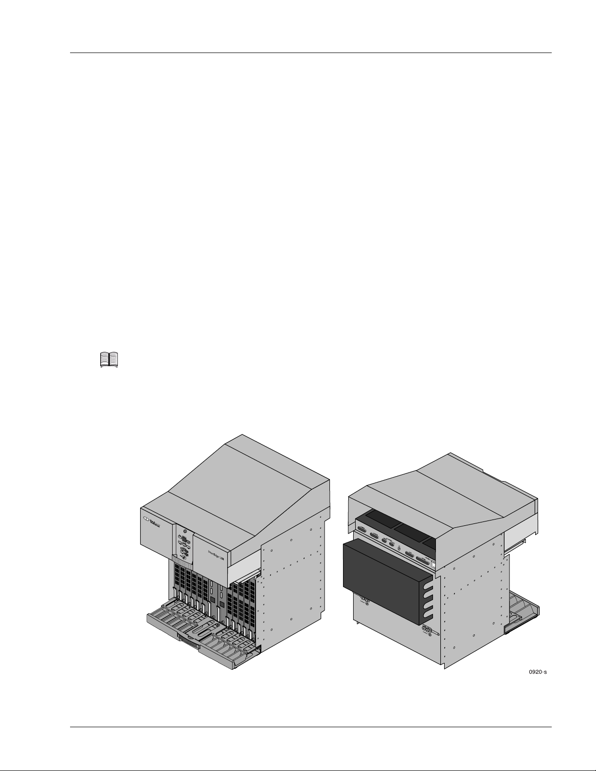
SmartEdge 1200 Chassis
The SmartEdge 1200 chassis is designed for mounting in a standard 19- or 23-inch rack. Figure 1-1 shows
the standard SmartEdge 1200 chassis; Figure 1-2 shows the SmartEdge 1200n chassis. Main features of the
chassis include:
• Chassis Card Cage
• Chassis Cooling
• Chassis Power
Chassis Card Cage
The SmartEdge 1200 chassis has a card cage with 14 slots. Two slots are dedicated to the controller cards
and 12 slots are available for a flexible combination of traffic cards.
All cards are installed at the front of the chassis. A cable tray provides the means to route the cables from
the front of the chassis to the external equipment. The cable tray requires no adjustments regardless of the
number and types of installed cables.
The rear of the chassis has connectors for alarm outputs, status inputs, dual external timing inputs for
synchronization, and dual RS-232 ports for local connections. Cable brackets at the rear of the chassis
provide the means for routing system cables and keeping them orderly.
System Components
Note The SmartEdge OS does not support the alarm, status, and RS-232 dial-up modem ports.
Electrostatic discharge (ESD) jacks are conveniently located on both the front and the rear of the chassis.
Figure 1-1 Standard SmartEdge 1200s Chassis
System Description 1-5
Page 20
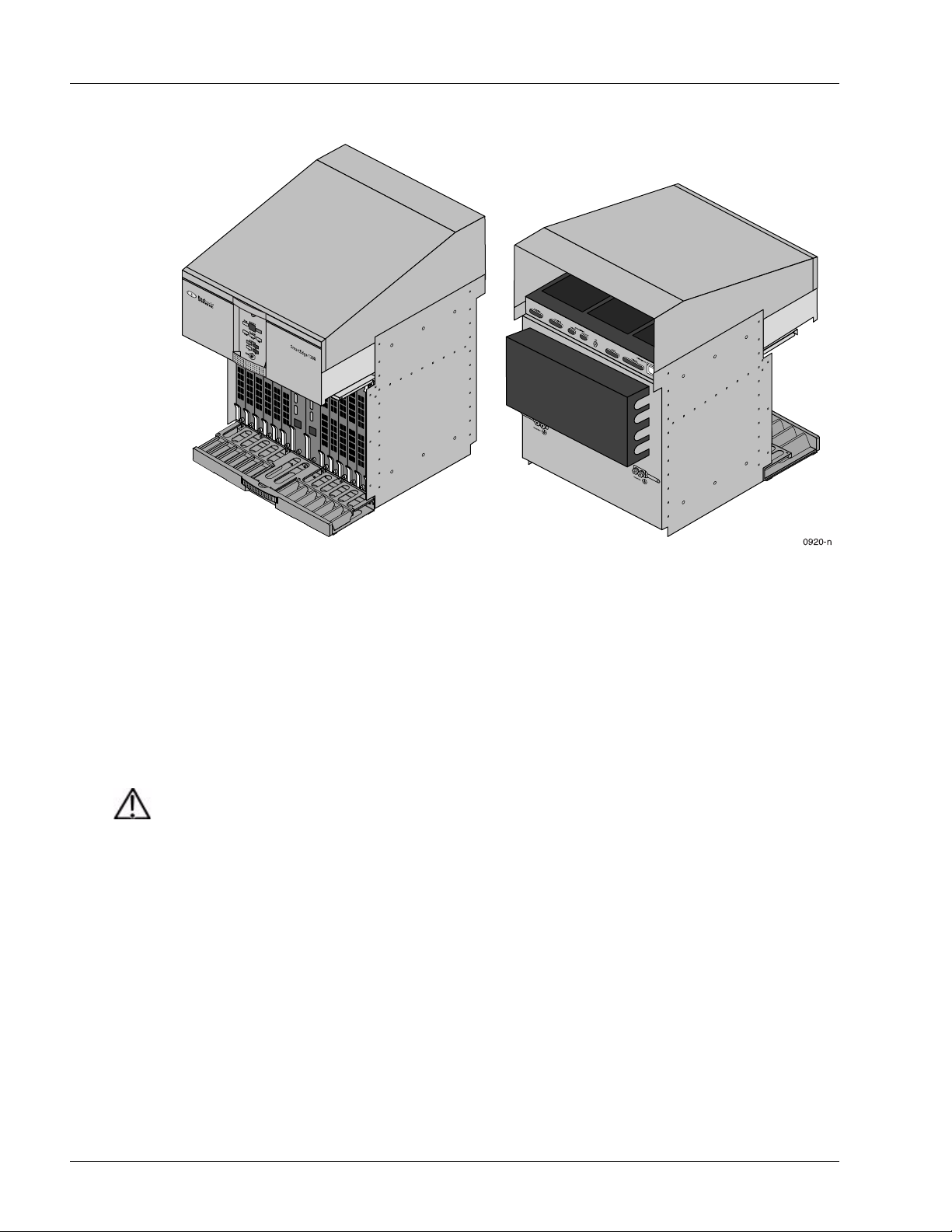
System Components
Figure 1-2 NEBS-Compliant SmartEdge 1200n Chassis
Chassis Cooling
Cooling for the chassis is provided by the fan tray, which is installed directly above the card slots. Six fans
provide the needed airflow from the bottom of the chassis to the top with exhaust at the rear of the chassis.
An air filter is installed below the card cage and filters incoming air before it reaches the cards.
A single fan failure does not impact the operation of the system; however, to prevent overheating, the unit
must be replaced as soon as possible. To maintain the airflow through the chassis, empty slots must have
blank cards installed.
Caution Risk of equipment damage. SmartEdge router cards can be damaged by lack of cooling when
Chassis Power
The SmartEdge 1200 router power architecture has two power zones, each with primary and backup
sources. Primary sources are referred to as A sources; backup sources are B sources. A1 refers to the
primary power source for zone 1; B1 refers to the backup power source for zone 1. Both zones 1 and 2 must
be connected for the chassis to be operational; the connections can be any combination of A and B sources.
For a fully redundant power configuration, all four sources must be connected.
Zone 1 sources provide power to slots 1 to 7 in the chassis; zone 2 sources provide power to slots 8 to 14.
The chassis fan tray is powered from either zone.
the chassis has empty slots. To reduce the risk, every slot must have a controller, traffic, or
blank card installed in it to ensure proper airflow through the chassis.
1-6 SmartEdge 1200 Router Hardware Guide
Page 21

Controller Cards
A controller card manages the system; it is responsible for the packet routing protocols, the SmartEdge OS
command-line interface (CLI), and communications with a network management system running the
NetOp™ Element Management System (EMS) software. The controller card also loads all configuration
information necessary for the traffic cards. Controller cards are installed in slots 7 and 8 in the
SmartEdge 1200 chassis. Controller cards are described in the following sections:
• Controller Card Versions
• Controller Card Features and Functions
Controller Card Versions
The SmartEdge router supports three versions of the controller cards:
• XCRP Controller card
Two versions of this controller card support either a DS-1 interface for BITS equipment (labeled
“XCRP-T1 BITS”) or an E1 interface for SSU equipment (labeled “XCRP-E1 SSU”).
• XCRP3 Controller card
Two versions of this card differ only in the total size of main memory. The interface to BITS or SSU
equipment is software selectable.
System Components
• XCRP4 Controller card
This controller card supports applications that require high volumes of traffic; it also supports more
subscribers than the other controller cards. Unlike the XCRP3 Controller card, the interface to BITS or
SSU equipment does not support the transmission of timing data to the external equipment.
Table 1-3 compares the XCRP and XCRP3 Controller cards.
Table 1-3 XCRP and XCRP3 Controller Card Comparison
Feature XCRP XCRP3
Processors Dual processors with shared memory that run
Control processor functions • SONET/SDH software
Main memory (total) 768 MB 768 or 1,280 MB
NVRAM No 512 KB DRAM with battery backup
Internal timing Stratum 3 oscillator
Real-time clock No Yes, synchronized with NTP server
External timing implementation
independently and perform different functions
• SmartEdge OS software
• NetOp EMS software
• External timing (synchronization) software
(±4.6 ppm with freerun, normal, and holdover
modes)
1
Separate hardware versions Software selectable
Dual processors with shared memory that run
independently and perform different functions
• SONET/SDH software
• SmartEdge OS software
• NetOp EMS software
• External timing (synchronization) software
Stratum 3 oscillator
(±4.6 ppm with freerun, normal, and holdover
modes)
Internal storage for system images
2
and files
384 or 512 MB 1 GB
System Description 1-7
Page 22

System Components
Table 1-3 XCRP and XCRP3 Controller Card Comparison (continued)
Feature XCRP XCRP3
External storage for core dumps
1 GB 1 GB (NEBS certified)
and system files
External ports 2 DB-9 (CRAFT 1, CRAFT 2)
3
1 10/100 Ethernet
1. Although either controller card can transmit data, the SmartEdge OS does not support the transmission of data to the external equipment.
2. Total storage on two internal storage devices.
3. The CRAFT 1 port is not supported.
2 DB-9 (CRAFT 1, CRAFT 2)3
1 10/100 Ethernet
Table 1-4 compares the XCRP3 Controller card with the XCRP4 Controller card.
Table 1-4 XCRP3 and XCRP4 Controller Card Comparison
Feature XCRP3 XCRP4
Processors Dual processors with shared memory that run
independently and perform different functions
Control processor functions • SONET/SDH software
• SmartEdge OS software
•NetOp EMS software
• External timing (synchronization) software
Main memory (total) 768 or 1,280 MB SDRAM 8 GB DDR-II SDRAM
NVRAM 512 KB DRAM with battery backup 512 KB DRAM with battery backup
Internal timing Stratum 3 oscillator
(±4.6 ppm with freerun, normal, and holdover
modes)
Four processors with shared memory that run
independently and perform different functions
• SONET/SDH software
• SmartEdge OS software
• NetOp EMS software
• External timing (synchronization) software
SONET minimum clock
(±20.0 ppm in freerun mode, normal mode only)
Real-time clock Yes, synchronized with NTP server Yes, synchronized with NTP server
External timing implementation
Internal storage for system
1
Software selectable
4
1 GB
2
Software selectable
3
2 GB
images and files
External storage for core dumps
1 GB (NEBS certified) 1 GB (NEBS certified)
and system files
External ports 2 DB-9 (CRAFT 1, CRAFT 2)
5
1 10/100 Ethernet
1. The SmartEdge OS does not support the transmission of data to the external equipment.
2. The XCRP3 can receive or transmit data.
3. The XCRP4 can receive data only.
4. Total storage on two internal storage devices.
5. The CRAFT 1 port is not supported.
6. Support for 1 Gbps depends on the release of the SmartEdge OS.
1 DB-9 (CRAFT)
1 10/100/1000 Ethernet
6
1-8 SmartEdge 1200 Router Hardware Guide
Page 23

Controller Card Features and Functions
A controller card has these features and functions:
• Processors
The XCRP and XCRP3 Controller cards have two processors. One processor runs low-level software,
including device drivers and equipment management software; the second processor runs the routing
and broadband remote access server (BRAS) software. The XCRP4 Controller card has four processors:
one processor runs the low-level software and the other three processors run the BRAS and routing
software.
Note Support for more than one processor to run the BRAS and routing software depends on the
release of the SmartEdge OS.
•Main memory
Synchronous dynamic RAM (SDRAM) is used by the SmartEdge OS shared databases that are
accessed by the traffic cards.
Note In a chassis with two controller cards, both cards must have the same memory configuration.
System Components
• NVRAM with battery
Each of the XCRP3 and XCRP4 Controller cards include 512 KB of non-volatile RAM (NVRAM),
which stores the current state of the system; because NVRAM is not affected by power failures or
system shutdown, the system can restore operations after such events. The NVRAM battery on the
XCRP4 Controller card is rechargeable; it is recharged from the power supplied to the SmartEdge router
during normal operations. The battery typically lasts more than two years when fully charged and
without benefit of being recharged by being powered on.
Note Support for NVRAM depends on the release of the SmartEdge OS.
• Internal, system, real-time, and time-of-day clocks
The internal clock onboard the XCRP and XCRP3 Controller cards is a Stratum 3 oscillator at ±4.6 ppm
that supports free-run, normal, and holdover modes; the internal clock on an XCRP4 Controller card is
a SONET minimum clock (SMC) at ±20.0 ppm in free-run and normal modes only.
The system clock refers to the clock that performs system hardware timing functions, regardless of the
source of its timing data. Using the SmartEdge OS, you can specify external equipment (external timing
mode), the received clock of a traffic card (line timing mode), or the internal clock on the controller card
(internal mode) as the source for the system clock.
The real-time clock (RTC) on the XCRP3 and XCRP4 Controller cards is initialized before the system
is shipped. It is not affected by power failures, system shutdown, or reload. The RTC uses the NVRAM
battery.
By default, the source for the transmit clock for the ports on a traffic card is its onboard clock.
Depending on the type of traffic card, the transmit clock for a port on a traffic card can use instead the
receive clock derived from an incoming signal to the port or the system clock. Because a port does not
interface to the source of the system clock directly, traffic card synchronization is independent of the
type of external timing equipment and the version of the controller card installed in the chassis.
System Description 1-9
Page 24
System Components
• Support for an external timing connection
Note The SmartEdge OS does not support transmission of data to external equipment.
• Internal storage for SmartEdge OS files
The time-of-day clock (TDC) for a SmartEdge router is implemented in software. When a system with
an XCRP3 or XCRP4 Controller card is powered on, the RTC sets the TDC; otherwise, the TDC is
undefined until it is configured and set using the SmartEdge OS. The TDC can be maintained by
synchronization with a Network Time Protocol (NTP) server. Periodically, the SmartEdge OS updates
the RTC based on the current value of the TDC.
All controller cards support a BITS (DS-1) or SSU (E1) interface as a source for the system clock. For
the XCRP Controller card, the type of interface is identified by the label suffix on the card: “T1 BITS”
for DS-1 and “E1 SSU” for E1; for the XCRP3 and XCRP4 Controller cards, the type of interface is
software selectable.
The external timing interfaces allow the system clock operation to be independent of the type of external
equipment and the framing of the external line.
A controller card has one or two CF cards (Type I), which store SmartEdge OS images and files.
SmartEdge OS storage is organized into three partitions: p0, p1, and /flash. The p0 and p1 partitions
each store a system image and its files; the memory on a controller card can be loaded from either
partition. The third partition, /flash, stores SmartEdge OS configuration files and other system- and
user-created data files.
Note The capacity of the CF cards can vary; the CF cards installed in the active and standby
controller cards need not have the same capacity.
• Optional CF card
A controller card has an external slot on the front panel in which you can install an optional Type I or
Type II CF card. The XCRP4 Controller card supports Type I CF cards only. When installed (the system
is shipped with the slot empty), the CF card captures crash dumps and provides an alternate source for
loading SmartEdge OS software, if it is not possible to download it over the network.
Caution Risk of data loss. You can corrupt the system if you attempt to install a CF card not obtained
from Redback
®
because these items have not been tested with the SmartEdge router. To
reduce the risk, use only the CF cards provided by Redback.
Note If a CF card is installed in the active controller card, the standby controller card, if installed,
must also have a CF card installed; however, for the XCRP and XCRP3 Controller cards, the
CF card types (Type I or Type II) need not match.
1-10 SmartEdge 1200 Router Hardware Guide
Page 25
System Components
• Two types of operations ports for system management access—Craft and Ethernet:
— The XCRP and XCRP3 Controller cards have two Craft ports, labeled “CRAFT 1” and “CRAFT 2”;
the XCRP4 Controller card has a single Craft port, labeled “CRAFT”. Each port has a DB-9
connector and provides an RS-232 connection to a local console terminal, a terminal server, or a
modem. The Craft port provides access to the SmartEdge OS CLI for configuring and monitoring
task; it is enabled on both the active and standby controller cards.
Note The CRAFT 2 port is the only enabled Craft port on the XCRP and XCRP3 Controller cards.
— All controller cards have a single Ethernet port with an RJ-45 connector that runs at 100 Mbps and
provides a connection to an Ethernet device such as a switch or hub. This port provides access to
the SmartEdge OS CLI from either a local or remote management workstation for configuring and
monitoring tasks. Using this port, the system can also communicate with a remote workstation that
is running the NetOp EMS software.
Note Support for 1-Gbps speed of the port on the XCRP4 Controller card depends on the release of
the SmartEdge OS.
Note The Ethernet management port on the standby controller card is disabled unless the card
becomes the active controller card.
• Temperature and voltage monitoring
Temperature is monitored at both air inlet and air outlet locations on a controller card;
an over-temperature interrupt signals the SmartEdge OS when the temperature rises above safe
operating conditions. Voltages are also monitored and reported to the SmartEdge OS. Administrators
can display both temperature and voltage data using commands in the SmartEdge OS CLI
• Fully redundant configuration:
— When two controller cards are installed in the SmartEdge 1200 chassis, one functions as the active
controller and the other card functions as the standby controller, providing full redundancy for
high-reliability networking requirements. In the event of a controller card failure, the redundant card
automatically becomes the active controller, thereby avoiding any unnecessary service disruption in
the network.
Note If you upgrade the active controller card with a new software release, the active controller
upgrades the standby controller.
— Redundancy extends to the console connections on the controller cards: the console ports can each
be connected to a terminal server, and the Ethernet management ports can be connected to the same
Ethernet hub, with individual cables.
— The software automatically switches to the external timing secondary source should the primary
source fail. If both sources fail, the active controller card uses an internal timing source.
System Description 1-11
Page 26
System Components
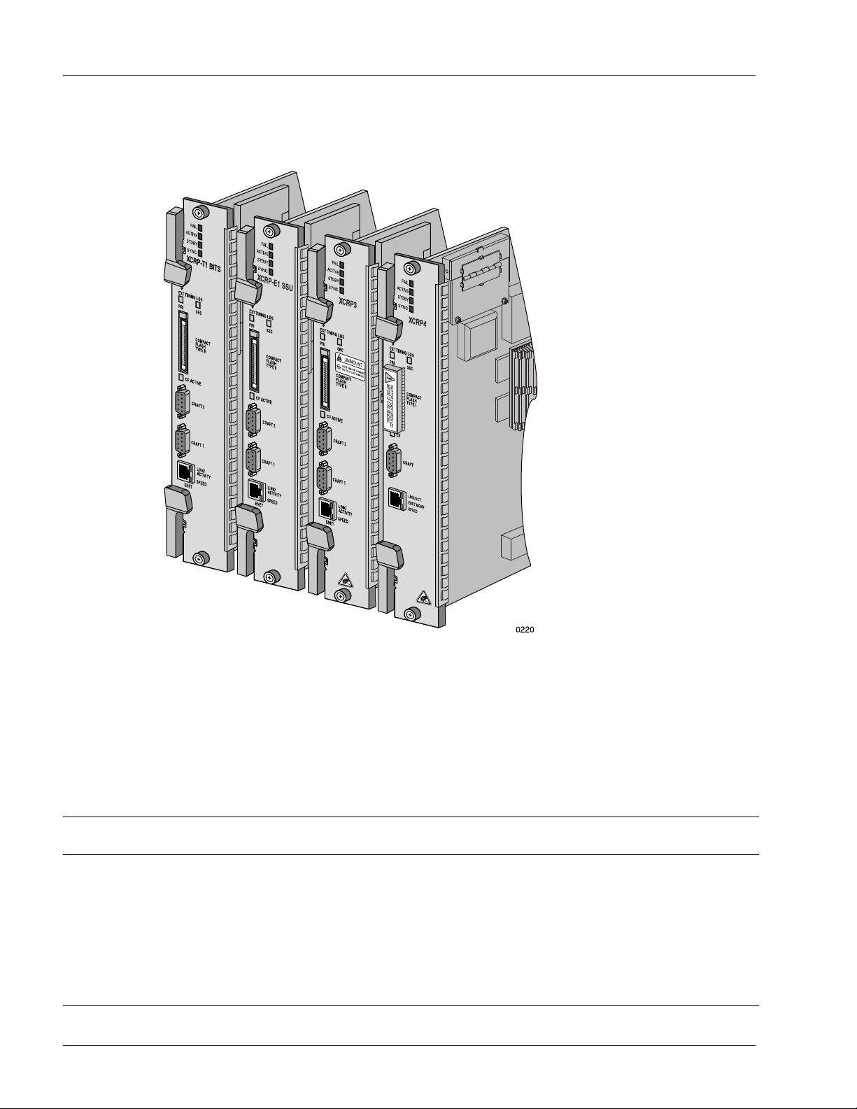
Figure 1-3 shows the front panels of the controller cards.
Figure 1-3 Controller Cards
Traffic Cards
Table 1-5 lists the traffic cards supported on the SmartEdge 1200 router; for more information about traffic
cards, see Chapter 2, “Traffic Card Descriptions.” In the table, the IR abbreviation specifies Intermediate
Reach.
Table 1-5 SmartEdge 1200 Traffic Cards
Type of Traffic Card/Description
ATM
4-port ATM OC-3c/STM-1c IR 12 4 Yes 2 None, 1+1 APS
Enhanced ATM OC-12c/STM-4c IR 12 1 No – None, 1+1 APS
Ethernet and Gigabit Ethernet
10/100 Ethernet 12 12 No – None
Fast Ethernet-Gigabit Ethernet 12 60, 2 No – None
Number
of Cards
Number
of Ports
Low-Density
1
Ver sio n
2
1-12 SmartEdge 1200 Router Hardware Guide
Low-Density
Ports
Protection
3
Ratios
Page 27

Table 1-5 SmartEdge 1200 Traffic Cards (continued)
System Components
Type of Traffic Card/Description
Number
of Cards
Number
of Ports
Low-Density
1
Ver sio n
2
Low-Density
Ports
Protection
3
Ratios
Gigabit Ethernet (first and second versions) 12 4 Yes 2 None
Gigabit Ethernet 3 12 4 No – None
Gigabit Ethernet 1020 (10-port) 12 10 No – None
Gigabit Ethernet 1020 (20-port) 6
4
20 No – None
10 Gigabit Ethernet 12 1 No – None
SONET/SDH
OC-192c/STM-64c 12 1 No – None, 1+1 APS
1. On optical cards, each port has separate connectors for the transmit (Tx) and receive (Rx) circuits.
2. The low-density version of a card provides a limited number of ports that are enabled through software entitlement.
3. Protection features for various types of cards and ports depend on the release of the SmartEdge OS; the system supports a mix of protected and unprotected
ports.
4. The 20-port GE1020 card requires two adjacent slots.
System Description 1-13
Page 28

System Components
1-14 SmartEdge 1200 Router Hardware Guide
Page 29

Chapter 2
Traffic Card Descriptions
This chapter describes each of the traffic cards that are currently available for the SmartEdge®1200 router.
Asynchronous Transfer Mode (ATM) cards include:
• ATM OC-12c/STM-4c Intermediate Reach Card
• ATM OC-3c/STM-1c Intermediate Reach Card
Fast Ethernet traffic cards include:
• 10/100 Ethernet and Fast Ethernet-Gigabit Ethernet Cards
Gigabit Ethernet traffic cards include:
• Gigabit Ethernet and Advanced Gigabit Ethernet
• Gigabit Ethernet 3
• Gigabit Ethernet 1020
• 10 Gigabit Ethernet
Packet over SONET/SDH traffic cards include:
• OC-192c/STM-64c Card
Note In the descriptions that follow, the term SmartEdge 1200 applies to any version of the chassis,
unless otherwise noted. The terms SmartEdge 1200s and SmartEdge 1200n refer to the
standard and NEBS-compliant versions of the chassis, respectively. Figures for the
SmartEdge 1200 chassis illustrate the SmartEdge 1200n chassis, unless otherwise noted.
In the descriptions that follow, the term controller card refers to any version of the
Cross-Connect Route Processor (XCRP) Controller card (XCRP, XCRP3, XCRP4), unless
otherwise noted.
The term Gigabit Ethernet applies to any Ethernet traffic card that supports a port speed of
1 Gbps or greater; unless explicitly stated, the speed of any Gigabit Ethernet port is 1 Gbps.
Traffic Card Descriptions 2-1
Page 30

A few traffic cards have a low-density version, on which a limited number of ports are enabled through
software entitlement. Table 2-1 lists the port data for traffic cards; in the table, IR, LR, and SR
abbreviations are used for Intermediate Reach, Long Reach, and Short Reach, respectively.
Table 2-1 Port Data for Traffic Cards
Type of Traffic Card/Description
ATM
ATM OC-12c/STM-4c IR
Enhanced ATM OC-12c/STM-4c IR
4-port ATM OC-3c/STM-1c IR
Ethernet and Gigabit Ethernet
10/100 Ethernet (12-port)
Fast Ethernet-Gigabit Ethernet
Gigabit Ethernet (first and second versions)
Gigabit Ethernet 3
Gigabit Ethernet 1020 (10-port)
Gigabit Ethernet 1020 (20-port)
10 Gigabit Ethernet
SONET/SDH
OC-192c/STM-64c 1 No –
Physical
Ports
1
1
4
12
60, 2
4
4
10
20
1
Low-Density
Versi on
No
No
Yes
No
No
Yes
No
No
No
No
Low-Density
Port Numbers
–
–
1, 3
–
–
1, 3
–
–
–
–
2-2 SmartEdge 1200 Router Hardware Guide
Page 31

ATM OC-12c/STM-4c Intermediate Reach Card
ATM OC-12c/STM-4c Intermediate Reach Card
The Enhanced ATM OC-12c/STM-4c IR card supports one SONET or SDH SMF port, which operates at
622 Mbps, and can be used either as optical line or optical trunk interfaces. In addition, the Enhanced ATM
OC-12c/STM-4c IR card can be used to support subscriber circuits. Figure 2-1 shows the front panel of the
Enhanced ATM OC-12c/STM-4c IR card.
Note The Enhanced ATM OC-12c/STM-4c IR card is also referred to as a second-generation ATM
OC-12 card.
The card uses two segmentation and reassembly (SAR) devices. The ingress SAR performs the reassembly
function on the incoming ATM cell stream from the physical (PHY) device. The egress SAR performs the
segmentation function to create the corresponding outgoing ATM cell stream.
The hardware provides header error control (HEC) framing for the port. The transmit clock can be derived
either from the active controller card or from the onboard local oscillator.
The second-generation ATM OC-12 card up to 16,000 ATM permanent virtual circuits (PVCs).
The SAR devices also support enhanced queuing and shaping functions for more granular control over
traffic management with two, four, or eight distinct class of service queues for each ATM PVC, and allow
a mix of priority- and class-based queuing for each ATM PVC. These additional capabilities allow the card
to support subscriber circuits. For information about ATM PVC and traffic management support, see the
Ports, Circuits, and Tunnels Configuration Guide for the SmartEdge OS.
Figure 2-1 ATM OC-12c/STM-4c IR Card
Traffic Card Descriptions 2-3
Page 32

ATM OC-12c/STM-4c Intermediate Reach Card
Table 2-2 lists the specifications for the Enhanced ATM OC-12c/STM-4c IR card.
Table 2-2 ATM OC-12c/STM-4c IR Card Specifications
Specification Value
General
Number of ports
Speed 622.08 Mbps
1
1
Protection (facility) 1+1 APS: Bidirectional or unidrectional;
revertive or nonrevertive switching
Interface Telcordia IR-1, SDH/STM-4 S-4.1
Link power budget
2
12 dB
Nominal wavelength 1,310 nm
Connector type LC
Cable type SMF
Compliance Telcordia GR-253, ANSI T1.102, ITU
G. 95 7
Transmitter
Optical output power –8.0 dBm (maximum)
–15.0 dBm (minimum)
Extinction ratio 8.2 dB (minimum)
Center wavelength range 1,274 to 1,356 nm
Spectral width (RMS) 2.5 nm (maximum)
Receiver
Wavelength range 1,274 to 1,356 nm
Minimum sensitivity –28 dBm
Overload level –8.0 dBm (minimum)
1. Each optical port has separate connectors for the transmit (Tx) and receive (Rx) circuits.
2. The link power budget is calculated using (minimum output power) – (minimum sensitivity) –
(optical path power penalty); the power penalty is 1.
2-4 SmartEdge 1200 Router Hardware Guide
Page 33

ATM OC-3c/STM-1c Intermediate Reach Card
ATM OC-3c/STM-1c Intermediate Reach Card
The ATM OC-3c/STM-1c Intermediate Reach (IR) card supports four SONET or SDH SMF ports, each of
which operates at 155 Mbps, and can be used either as optical line or optical trunk interfaces. Figure 2-2
shows the front panel of the ATM OC-3c/STM-1c IR card. A low-density version provides two ports that
are enabled through software entitlement.
Note The 4-port version is referred to as a second-generation ATM OC-3 card.
The card uses two SAR devices, which perform the reassembly function on the incoming ATM cell stream
from the PHY device and the segmentation function to create the corresponding outgoing ATM cell stream.
The hardware provides HEC framing for each port; the transmit clock can be derived either from the active
controller card or from the onboard local oscillator.
The second-generation ATM OC-3c/STM-1c card has increased memory for each port and offers higher
performance and support for more ATM virtual paths (VPs) and PVCs than an earlier version of the card.
The SAR devices support two, four, or eight distinct class of service queues for each ATM PVC, allowing
a mix of priority- and class-based queuing for each ATM PVC.
For information about ATM VPs and PVC support, see the Ports, Circuits, and Tunnels Configuration
Guide for the SmartEdge OS. A low-density version of this card provides two ports that are enabled
through software entitlement.
Figure 2-2 ATM OC-3c/STM-1c IR Card
Traffic Card Descriptions 2-5
Page 34

ATM OC-3c/STM-1c Intermediate Reach Card
Table 2-3 lists the specifications for the 4-port ATM OC-3c/STM-1c IR card.
Table 2-3 ATM OC-3c/STM-1c IR Card Specifications
Specification Value
General
Number of ports
Speed 155.52 Mbps
1
2 or 4
Protection 1+1 APS: Bidirectional or unidrectional;
revertive or nonrevertive switching
Interface Telcordia IR-1, SDH/STM-1 S-1.1
Link power budget
2
12 dB
Nominal wavelength 1,310 nm
Connector type LC
Cable type SMF
Compliance Telcordia GR-253, ANSI T1.102, ITU G.957
Transmitter
Optical output power –8.0 dBm (maximum)
–15.0 dBm (minimum)
Center wavelength range 1,261 to 1,360 nm
Extinction ratio 8.2 dB (minimum)
Spectral width (RMS) 7.7 nm (maximum)
Receiver
Wavelength range 1,260 to 1,360 nm
Minimum sensitivity –28 dBm
Overload level –8.0 dBm (minimum)
1. Each optical port has separate connectors for the transmit (Tx) and receive (Rx) circuits.
2. The link power budget is calculated using (minimum output power) – (minimum sensitivity)
– (optical path power penalty); the power penalty is 1.
2-6 SmartEdge 1200 Router Hardware Guide
Page 35

10/100 Ethernet and Fast Ethernet-Gigabit Ethernet Cards
10/100 Ethernet and Fast Ethernet-Gigabit Ethernet Cards
The 10/100 Ethernet card provides 12 copper-based 10Base-T or 100Base-TX ports with individually
selectable speeds of 10 Mbps or 100 Mbps. The Fast Ethernet-Gigabit Ethernet (FE-GE) card provides 60
copper-based 10Base-T or 100Base-TX ports with selectable speeds of 10 Mbps or 100 Mbps. The FE-GE
card also has two copper-based GE ports with selectable speeds of 100 or 1000 Mbps. Figure 2-3 shows
the front panels of the copper-based Ethernet cards.
Figure 2-3 10/100 and Fast Ethernet-Gigabit Ethernet Cards
Traffic Card Descriptions 2-7
Page 36

Transceiver-Based Gigabit Ethernet Cards
Table 2-4 lists the specifications for the 10/100 Ethernet and FE-GE traffic cards.
Table 2-4 10/100 and FE-GE Card Specifications
Specification 10/100 FE-GE
Number of ports 12 60 10/100; 2 100/1000
Speed 10 or 100 Mbps
Protection None None
Protocol 10 Mbps: 10Base-T
Line code 10 Mbps: Manchester coding
Negotiate flow control No Yes
Interface Electrical Electrical
Impedance 100 ohms 100 ohms
Connector type RJ-45 MRJ21
Cable type
Compliance IEEE 802.3, 802.3u IEEE 802.3, 802.3u
1. In addition to RJ-45 connectors for the GE ports, the FE-GE card has 5 MRJ21 connectors, each of which supports 12 FE ports;
the MRJ21 breakout cable has RJ-45 connectors for the individual ports.
2. The shielded cable must be grounded at both ends.
2
(user selectable, auto-sensing)
100 Mbps: 100Base-TX
100 Mbps: MLT-3
2 pair,
Category 5 shielded-twisted pair
10, 100, or 1000 Mbps
(user selectable, 100 Mbps is auto-sensing)
10 Mbps: 10Base-T
100 Mbps: 100Base-TX
1000 Mbps: 1000Base-T
10 Mbps: Manchester coding
100 Mbps: MLT-3
1000 Mbps: PAM-5
1
, RJ-45
2 pair,
Category 5 shielded-twisted pair
Transceiver-Based Gigabit Ethernet Cards
The SmartEdge routers support the following transceiver-based Gigabit Ethernet cards:
• Gigabit Ethernet—First version
• Advanced Gigabit Ethernet—Second version
• Gigabit Ethernet 3—Third version
• Gigabit Ethernet 1020 (10-port)
• Gigabit Ethernet 1020 (20-port)
• 10 Gigabit Ethernet
2-8 SmartEdge 1200 Router Hardware Guide
Page 37

Transceiver-Based Gigabit Ethernet Cards
Gigabit Ethernet ports on these cards require a gigabit interface converter (GBIC), a small form-factor
pluggable (SFP), or a 10-Gbps SFP (XFP) transceiver in each port. Table 2-5 lists the transceiver type for
each Gigabit Ethernet card.
Table 2-5 Transceiver Types for Gigabit Ethernet Cards
Traffic Card Transceiver Type
Gigabit Ethernet (first and second versions) GBIC
Gigabit Ethernet 3 SFP
Gigabit Ethernet 1020 (10-port) SFP
Gigabit Ethernet 1020 (20-port) SFP
10 Gigabit Ethernet XFP
These transceivers are described in the Transceivers for SmartEdge Traffic Cards document.
Figure 2-4 shows the front panels of these cards with transceivers installed in their ports.
Figure 2-4 Gigabit Ethernet Cards
Traffic Card Descriptions 2-9
Page 38

Transceiver-Based Gigabit Ethernet Cards
These traffic cards are described in the following sections:
• Gigabit Ethernet and Advanced Gigabit Ethernet
• Gigabit Ethernet 3
• Gigabit Ethernet 1020
• 10 Gigabit Ethernet
Gigabit Ethernet and Advanced Gigabit Ethernet
The Gigabit Ethernet and Advanced Gigabit Ethernet cards are the first and second versions of the 4-port
Gigabit Ethernet card, respectively. Each card provides four optical Ethernet ports; a low-density version
of the card provides two ports that are enabled through software entitlement. The Gigabit Ethernet card
supports 256 MB of memory for each Packet Processing ASIC (PPA) on the card; the Advanced version
supports 512 MB for each PPA. The following GBIC transceivers are supported on any port on either card:
• 1000Base-SX—Short reach
• 1000Base-LX—Long reach
• 1000Base-LX70—Extended reach
• 1000Base-T—Copper
Either card can have any combination of the listed types of GBIC transceivers installed.
Caution Risk of data loss. You can corrupt the system if you attempt to install transceivers (GBICs,
SFPs, or XFPs) that are not purchased from Redback
®
because these items have not been
tested with the SmartEdge router. To reduce the risk, install only the transceivers purchased
from Redback.
Table 2-6 lists the specifications for the first and second versions of the Gigabit Ethernet cards for the
various GBIC transceivers.
Table 2-6 Gigabit Ethernet Card Specifications, First and Second Versions
Specification SX LX LX70 TX
Number of ports2
Speed 1 Gbps 1 Gbps 1 Gbps 1 Gbps
Protection None None None None
Interface 1000Base-SX 1000Base-LX 1000Base-LX70 1000Base-T
Line code 8B/10B 8B/10B 8B/10B PAM-5
Negotiate flow control
3
2 or 4 2 or 4 2 or 4 2 or 4
Yes Yes Ye s Yes
1
Transceiver type GBIC GBIC GBIC GBIC
Compliance IEEE 802.3, 802.3z IEEE 802.3, 802.3z IEEE 802.3, 802.3z IEEE 802.3, 802.3ab,
1. The TX GBIC transceiver does not comply with the Network Equipment Building Standards (NEBS) electrostatic discharge (ESD) requirement.
2. Each optical port has separate connectors for the transmit (Tx) and receive (Rx) circuits.
3. The extent of the support for flow control depends on the release of the SmartEdge OS.
802.3z
2-10 SmartEdge 1200 Router Hardware Guide
Page 39

Gigabit Ethernet 3
The Gigabit Ethernet 3 (GE3) card is the third version of the 4-port Gigabit Ethernet card. It is designed for
traffic management, with the second generation of the PPAs, each of which supports 1 GB of memory and
can process data internally at a much higher rate than the PPAs on the first and second versions of the
Gigabit Ethernet card.
Any combination of the following types of SFP optical and copper transceivers are supported on any port
on the card:
• 1000Base-SX—Short reach
• 1000Base-LX—Long reach
• 1000Base-ZX—Extended reach
• 1000Base-T—Copper
• 1000Base-CWDM—Coarse wavelength-division multiplexing (CWDM)
• 1000Base-DWDM—Dense wavelength-division multiplexing (DWDM)
Caution Risk of data loss. You can corrupt the system if you attempt to install transceivers (GBICs,
SFPs, or XFPs) that are not purchased from Redback because these items have not been tested
with the SmartEdge router. To reduce the risk, install only the transceivers purchased from
Redback.
Transceiver-Based Gigabit Ethernet Cards
Table 2-7 and Table 2-8 list the GE3 card specifications for the various SFP transceivers.
Table 2-7 GE3 Card Base-SX, Base-LX, Base-ZX, and Base-T Specifications
Specification SX LX ZX TX
Number of ports
Speed 1 Gbps 1 Gbps 1 Gbps 1 Gbps
Protection None None None None
Interface 1000Base-SX 1000Base-LX 1000Base-ZX 1000Base-T
Line code 8B/10B 8B/10B 8B/10B PAM-5
Negotiate flow control
Transceiver type SFP SFP SFP SFP
Compliance IEEE 802.3,
1. Each optical port has separate connectors for the transmit (Tx) and receive (Rx) circuits.
2. The extent of the support for flow control depends on the release of the SmartEdge OS.
1
4444
2
Yes Yes Yes Yes
802.3z
IEEE 802.3,
802.3z
IEEE 802.3,
802.3z
IEEE 802.3, 802.3ab,
802.3z
Traffic Card Descriptions 2-11
Page 40

Transceiver-Based Gigabit Ethernet Cards
Table 2-8 GE3 Card Base-CWDM and Base-DWDM Specifications
Specification CWDM DWDM
Number of ports
Speed 1 Gbps 1 Gbps
Protection None None
Interface 1000Base-CWDMnnnn
Line code 8B/10B 8B/10B
Negotiate flow control
Transceiver type SFP SFP
Compliance IEEE 802.3, 802.3z IEEE 802.3, 802.3z
1. Each optical port has separate connectors for the transmit (Tx) and receive (Rx) circuits.
2. Nominal wavelength.
3. The range of International Telecommunications Union (ITU) channels is 17 to 60.
4. The extent of the support for flow control depends on the release of the SmartEdge OS.
1
4
Gigabit Ethernet 1020
44
2
1000Base-DWDMITUnn
Yes Yes
3
The Gigabit Ethernet 1020 (GE1020) cards are designed for traffic management, with the second
generation of the PPAs, each of which supports 1 GB of memory and can process data internally to match
the speed of the ports. Two versions of the GE1020 card provide 10 or 20 optical ports, each of which runs
at 1 Gbps. Any of the following types of SFP optical transceivers are supported on any of the ports:
• 1000Base-SX—Short reach
• 1000Base-LX—Long reach
• 1000Base-ZX—Extended reach
• 1000Base-T—Copper
• 1000Base-CWDM—CWDM
• 1000Base-DWDM—DWDM
Caution Risk of data loss. You can corrupt the system if you attempt to install transceivers (GBICs,
SFPs, or XFPs) that are not purchased from Redback because these items have not been tested
with the SmartEdge router. To reduce the risk, install only the transceivers purchased from
Redback.
2-12 SmartEdge 1200 Router Hardware Guide
Page 41

Transceiver-Based Gigabit Ethernet Cards
Table 2-9 and Table 2-10 list the specifications for the GE1020 cards for the various SFP transceivers.
Table 2-9 GE1020 Card Base-SX, Base-LX, Base-ZX, and Base-T Specifications
Specification SX LX ZX TX
Number of ports
Speed 1 Gbps 1 Gbps 1 Gbps 1 Gbps
Protection None None None None
Interface 1000Base-SX 1000Base-LX 1000Base-ZX 1000Base-T
Line code 8B/10B 8B/10B 8B/10B PAM-5
Negotiate flow control
Transceiver type SFP SFP SFP SFP
1
10 or 20 10 or 20 10 or 20 10 or 20
2
Yes Yes Yes Ye s
Compliance IEEE 802.3,
802.3z
1. Each optical port has separate connectors for the transmit (Tx) and receive (Rx) circuits.
2. The extent of the support for flow control depends on the release of the SmartEdge OS.
IEEE 802.3,
802.3z
IEEE 802.3,
802.3z
Table 2-10 GE1020 Card Base-CWDM and Base-DWDM Specifications
Specification CWDM DWDM
Number of ports
Speed 1 Gbps 1 Gbps
Protection None None
Interface 1000Base-CWDMnnnn
Line code 8B/10B 8B/10B
Negotiate flow control
Transceiver type SFP SFP
Compliance IEEE 802.3, 802.3z IEEE 802.3, 802.3z
1. Each optical port has separate connectors for the transmit (Tx) and receive (Rx) circuits.
2. Nominal wavelength.
3. The range of ITU channels is 17 to 60.
4. The extent of the support for flow control depends on the release of the SmartEdge OS.
1
10 or 20 10 or 20
2
4
Yes Ye s
1000Base-DWDMITUnn
IEEE 802.3, 802.3ab,
802.3z
3
Traffic Card Descriptions 2-13
Page 42

Transceiver-Based Gigabit Ethernet Cards
10 Gigabit Ethernet
The 10 Gigabit Ethernet (10GE) card is designed for traffic management, with the second generation of the
PPAs, each of which supports 1 GB of memory and can process data internally to match the speed of the
port, which runs at 10 Gbps. Any of the following types of 10-Gbps XFP transceivers are supported on the
port:
• 10000Base-SR
• 10000Base-LR
• 10000Base-ER
Caution Risk of data loss. You can corrupt the system if you attempt to install transceivers (GBICs,
SFPs, or XFPs) that are not purchased from Redback because these items have not been tested
with the SmartEdge router. To reduce the risk, install only the transceivers purchased from
Redback.
Table 2-11 lists the 10GE card specifications for the various XFP transceivers.
Table 2-11 10GE Card Specifications
Specification SR LR ER
Number of ports
1
111
Speed 10 Gbps 10 Gbps 10 Gbps
Protection None None None
Interface 10GBase-SR 10GBase-LR 10GBase-ER
Line code 64B/66B 64B/66B 64B/66B
Negotiate flow control
Transceiver type XFP XFP XFP
Compliance IEEE 802.3ae, 802.3 LLC,
1. The port has separate connectors for the transmit (Tx) and receive (Rx) circuits.
2. The extent of the support for flow control depends on the release of the SmartEdge OS.
2
Yes Ye s Ye s
802.3 SNAP/LLC, 802.3ae
IEEE 802.3ae, 802.3 LLC,
802.3 SNAP/LLC, 802.3ae
IEEE 802.3ae, 802.3 LLC,
802.3 SNAP/LLC, 802.3ae
2-14 SmartEdge 1200 Router Hardware Guide
Page 43

OC-192c/STM-64c Card
The OC-192c/STM-64c card provides a single 9.9-Gbps SONET or SDH port, which is used as either an
optical line or optical trunk interface.
The card supports three types of XFP transceivers:
• SR-1—Transmitter range of 1,290 to 1,330 nm
• IR-2—Transmitter range of 1,530 to 1,565 nm
• LR-2b—Transmitter range of 1,530 to 1,565 nm
For information about the transceivers, see the Transceivers for SmartEdge Traffic Cards document.
Figure 2-5 shows the OC-192c/STM-64c traffic card.
The OC-192c/STM-64c card supports the Point-to-Point Protocol (PPP), high-level data-link control
(HDLC), and Frame Relay encapsulations. It also supports a frame size of up to 9600 bytes.
Figure 2-5 OC-192c/STM-64c Card
OC-192c/STM-64c Card
Traffic Card Descriptions 2-15
Page 44

OC-192c/STM-64c Card
Table 2-12 lists the OC-192c/STM-64c card specifications for various XFP transceivers.
Table 2-12 OC-192c/STM-64c Card Specifications
Specification SR IR LR
Number of ports
Speed 10 Gbps 10 Gbps 10 Gbps
Protection None, 1+1 APS None, 1+1 APS None, 1+1 APS
Interface SR-1 IR-2 LR-2b
Transceiver type XFP XFP XFP
1
111
Compliance Telcordia GR-253-CORE
ITU-T-707, OIF-SPI4-02.1
1. The port has separate connectors for the transmit (Tx) and receive (Rx) circuits.
Telcordia GR-253-CORE
ITU-T-707, OIF-SPI4-02.1
Telcordia GR-253-CORE
ITU-T-707, OIF-SPI4-02.1
2-16 SmartEdge 1200 Router Hardware Guide
Page 45

Chapter 3
Preparing for Installation
This chapter describes planning for the hardware installation, including site and management access
requirements for the SmartEdge
Topics in this chapter include:
• Planning the Site and Installation
• Selecting the Type of Management Access
• Gathering Cables and Tools
After you complete the tasks in this chapter, you are ready to install the system as described in Chapter 4,
“Installing the Hardware.”
Note In the descriptions that follow, the term SmartEdge 1200 applies to any version of the chassis,
unless otherwise noted. The terms SmartEdge 1200s and SmartEdge 1200n refer to the
standard and NEBS-compliant versions of the chassis, respectively. Figures for the
SmartEdge 1200 chassis illustrate the SmartEdge 1200n chassis, unless otherwise noted.
In the descriptions that follow, the term controller card refers to any version of the
Cross-Connect Route Processor (XCRP) Controller card (XCRP, XCRP3, XCRP4), unless
otherwise noted.
The term Gigabit Ethernet applies to any Ethernet traffic card that supports a port speed of
1 Gbps or greater; unless explicitly stated, the speed of any Gigabit Ethernet port is 1 Gbps.
®
1200 router.
Planning the Site and Installation
This section describes:
• Select the Installation Site
— Agency Compliance Information
— Electrical Specifications
— Electrical Power Connections
— Environmental Requirements
— Physical Specifications
Preparing for Installation 3-1
Page 46

Planning the Site and Installation
• Select the Rack
• Select the Installation Method
• Warnings
— Equipment and Personal Safety Warnings
— DC Power Source Warnings
Select the Installation Site
Select the installation site for the SmartEdge 1200 router, considering maintenance, electrical, and
ventilation requirements. Also, consider current and future cabling requirements. The following topics
provide information to assist you with site selection:
• Agency Compliance Information
• Electrical Specifications
• Electrical Power Connections
• Environmental Requirements
• Physical Specifications
Agency Compliance Information
Table 3-1 lists the agency compliance standards to which the SmartEdge 1200 hardware is designed to
meet.
Table 3-1 Agency Compliance Standards
Product Safety Emissions Immunity NEBS Level 3
UL 60950
CSA 22.2 No. 60950
IEC60950
EN60950
AS/NZS 60950
1. The TX GBIC transceiver does not comply with the Network Equipment Building Standards (NEBS) electrostatic discharge (ESD)
requirement.
Caution Risk of equipment damage. The intrabuilding ports of the traffic cards are suitable for
connection to intrabuilding or unexposed wiring or cabling only. The intrabuilding ports of
the traffic cards must not be metallically connected to interfaces that connect to the outside
plant (OSP) or its wiring. These interfaces are designed for use in intrabuilding interfaces only
(Type 2 or Type 4 ports as described in GR-1089-CORE, Issue 4) and require isolation from
the exposed OSP cabling. The addition of primary protectors is not sufficient protection in
order to connect these interfaces metallically to OSP wiring.
FCC part 15, Class A
ETSI EN300 386
CISPR 22 Class A
VCCI Class A
EN55022, Class A
AS/NZA 3548 Class A
EN61000-4-2
EN61000-4-3
EN61000-4-4
EN61000-4-5
EN61000-4-6
ETSI EN300 386
1
GR-63-CORE
GR-1089-CORE
Note The SmartEdge 1200 is suitable for installation in Network Telecommunication Facilities and
as part of the Common Bonding Network (CBN).
3-2 SmartEdge 1200 Router Hardware Guide
Page 47

Electrical Specifications
Table 3-2 lists the electrical specifications for the SmartEdge 1200 router.
Table 3-2 Electrical Specifications
Requirement Value
Input voltage, nominal -48.0 Vdc
Input voltage range –40.0 Vdc to –57.5 Vdc
Total input power, maximum 3840 VA
Input power per feed, maximum 1920 VA
Input current rating per feed 40 Adc@–48 Vdc
Source DC power requirement • Sufficient to supply the rated input current
Number of input feeds 4: 2 from battery plant A and 2 from battery plant B
Table 3-3 lists the operating and inrush current (in amperes) at –48 VDC for active traffic cards.
Table 3-3 Operating and Inrush Current for Traffic Cards at –48 VDC
Planning the Site and Installation
• Local codes apply
Component Operating Current Inrush Current
1
ATM
Enhanced ATM OC-12c/STM-4c
4-port ATM OC-3c/STM-1c
1.80
1.88
4.98
4.96
Ethernet and Gigabit Ethernet
10/100 Ethernet
FE-GE (60-port FE, 2-port GE)
Gigabit Ethernet (first and second versions)
Gigabit Ethernet 3
Gigabit Ethernet 1020 (10-port)
Gigabit Ethernet 1020 (20-port)
10 Gigabit Ethernet
1.44
2.80
1.56
2.24
2.95
3.70
2.72
4.20
2
0.62
4.04
3
4.00
14.20
12.403
10.52
3
3
SONET/SDH
OC-192c/STM-64c 2.72 10.52
1. Inrush current occurs during power on or during the installation of a component in a powered-on chassis. Unless
noted, maximum duration is 4 ms.
2. Maximum duration is 28 ms
3. Maximum duration is 20 µs.
3
Preparing for Installation 3-3
Page 48

Planning the Site and Installation
Table 3-4 lists the operating and inrush current (in amperes) at –48 VDC for SmartEdge 1200 chassis
components. Inrush current occurs during power on or during the installation of a component in a
powered-on chassis. Unless noted, maximum duration is 4 ms.
Table 3-4 Operating and Inrush Current for Chassis Components at –48 VDC
Component Operating Current Inrush Current
Controllers
XCRP (active or standby)
XCRP3 (active or standby)
XCRP4 (active or standby)
Chassis
Fan tray (nominal speed)
Fan tray (high speed)
1. Maximum duration is 25 ms.
2. Maximum duration is 3 ms.
Electrical Power Connections
The SmartEdge 1200 router power architecture has connectors for two power zones, each with primary and
backup sources. Zone 1 powers slots 1 to 7; zone 2 powers slots 8 to 14. Both zones provide power to the
fan tray. Both zones 1 and 2 must be connected for the chassis to be operational.
Primary sources are designated as A sources; backup sources are B sources. A1 refers to the primary power
source for zone 1; B1 refers to the backup power source for zone 1. For a fully redundant power
configuration, all four sources must be connected. Table 3-5 lists all possible power configurations
Table 3-5 Slot and Power Zone Configuration Options
Slot Power Configuration Power Zone Configuration Power Connection Options
All slots have redundant power. Redundant power for zones 1 and 2 A1, B1, A2, B2
1.00
0.86
2.21
2.20
5.40
4.60
3.00
0.52
6.60
6.602
1
2
All slots have nonredundant power. Nonredundant power for zones 1 and 2 A1, A2 or
Slots 1 to 7 have nonredundant power.
Slots 8 to 14 have redundant power.
Slots 1 to 7 have redundant power.
Slots 8 to 14 have nonredundant power.
Power to both zones
Redundant power for zone 2 only
Power to both zones
Redundant power for zone 1 only
B1, B2 or
A1, B2 or
B1, A2
A1, A2, B2 or
B1, A2, B2
A1, B1, A2 or
A1, B1, B2
Table 3-6 lists the possible power conditions that result in a nonoperable SmartEdge 1200 chassis. These
conditions can occur for either or both of the following causes:
• The original power configuration was not fully redundant.
• Both the primary and the backup power source for a zone has failed.
3-4 SmartEdge 1200 Router Hardware Guide
Page 49

Planning the Site and Installation
Table 3-6 Nonoperable Power Conditions
Slot Power Condition Power Zone Condition Currently Available Power
Slots 1 to 7 have no power.
Slots 8 to 14 have redundant power.
Slots 1 to 7 have no power.
Slots 8 to 14 have nonredundant power.
Slots 1 to 7 have redundant power.
Slots 8 to 14 have no power.
Slots 1 to 7 have nonredundant power.
Slots 8 to 14 have no power.
No power for zone 1
Redundant power for zone 2
No power for zone 1
Nonredundant power for zone 2
Redundant power for zone 1
No power for zone 2
Nonredundant power for zone 1
No power for zone 2
A2, B2
A1 and B1 are not connected
or have failed.
A2 or B2
A1 and B1 are not connected
or have failed.
A1, B1
A2 and B2 are not connected
or have failed.
A1 or B1
A2 and B2 are not connected
or have failed.
Each power connection must be able to supply a minimum 50 amperes. DC power connections require
copper wire of a size suitable for the installation in accordance with the National Electrical Code (in the
United States) or applicable local jurisdiction (outside the United States) installation requirements. An
external fuse panel, either a stand-alone unit or incorporated in a DC power supply system, or a circuit
breaker panel, is required for power on and power off control.
Caution Risk of equipment damage. A DC-powered system uses –48 VDC power, is powered from a
fuse panel, and can be damaged by overloaded circuits. To reduce the risk, ensure that the
fuses in the external fuse panel are suitably rated for the installation in accordance with the
National Electrical Code (in the United States) or applicable local jurisdiction (outside the
United States) installation requirements.
Environmental Requirements
The installation area for the SmartEdge 1200 hardware must allow the following clearances:
• A minimum of 6.0 inches (15.2 cm) at the back of the chassis (for cable routing)
• A minimum of 20.0 inches (50.8 cm) at the front of the chassis (for maintenance)
Caution Risk of equipment damage. A SmartEdge router can be damaged by lack of proper cooling
and ventilation. To reduce the risk, never install the chassis in an unventilated area, and always
ensure that cooling equipment sufficient to maintain a temperature of less than 104°F (40°C)
is available.
Table 3-7 lists the environmental requirements for the installation site of the SmartEdge 1200 hardware.
Table 3-7 Environmental Requirements
Specification Value
Cooling Forced air (fan cooled)
Operating temperature, short term
Operating temperature, long term
Operating humidity 5 to 95% (noncondensing)
1
23° to 131°F (–5° to 55°C)
2
41° to 104°F (5° to 40°C)
Preparing for Installation 3-5
Page 50

Planning the Site and Installation
Table 3-7 Environmental Requirements (continued)
Specification Value
Operating altitude 0 to 10,000 ft (3,048m)
Earthquake Telcordia 63-CORE Zone 4-compliant
Thermal dissipation, maximum 3840 watts (13,103 BTU/hour)
1. Short term refers to a period of time not more than 96 consecutive hours and a total of not more than
15 days in one year (360 hours in any given year, but no more than 15 occurrences during that year).
2. Long term refers to normal operating conditions.
Physical Specifications
Table 3-8 lists the SmartEdge 1200 physical specifications.
Table 3-8 SmartEdge 1200 Physical Specifications
Mechanical Specification Value
1200s chassis dimensions 19.5 inches (49.50 cm) height
17.3 inches (43.80 cm) width
22.7 inches (57.7 cm) depth
1200n chassis dimensions 21.2 inches (54.0 cm) height
17.3 inches (43.8 cm) width
22.7 inches (57.7 cm) depth
Chassis weight 55 lb (25 kg) all card slots empty, ready for installation
110 lb (50 kg) all card slots filled
Chassis mounting 19- or 23-inch rack
To t a l s l ot s 14
Traffic card slots 12
Common equipment slots 2
Card dimensions 9.75 inches (24.80 cm) height
12.73 inches (32.30 cm) depth
Note Chassis depth dimension includes the front cable tray and the power safety cover.
3-6 SmartEdge 1200 Router Hardware Guide
Page 51

Planning the Site and Installation
Figure 3-1 and Figure 3-2 show these dimensions for the SmartEdge 1200n and 1200s chassis, respectively.
Figure 3-1 SmartEdge 1200n Chassis Dimensions
Figure 3-2 SmartEdge 1200s Chassis Dimensions
Preparing for Installation 3-7
Page 52

Planning the Site and Installation
Table 3-9 lists the connections for the traffic cards and operations ports.
Table 3-9 SmartEdge 1200 Connections
Traffic Card Connections Connector Type
ATM
ATM OC-12c/STM-4c (any version)
ATM OC-3c/STM-1c
Ethernet
10/100 Ethernet
FE-GE
Gigabit Ethernet (first and second versions)
Gigabit Ethernet 3
Gigabit Ethernet 1020 (10- and 20-port versions)
10 Gigabit Ethernet
SONET/SDH
OC-192c/STM-64c (any XFP version) LC, front chassis access
Operations Connections Connector Type
Management workstation (LAN)
Craft console (RS-232)
External Timing, Primary and Secondary (DS-1 or E1)
Modem, SL7 and SL8 (RS-232)
3
Alarm
Status/Ctl
Power and chassis ground
1. The front panel has 5 MRJ21 connectors, each supporting 12 FE ports; a breakout cable, which uses RJ-45 connectors for the
2. Connector type is determined by the gigabit interface converter (GBIC) version installed in the port.
3. The SmartEdge OS does not support this connection.
3
individual ports, is available from Redback
3
®
.
LC, front chassis access
LC, front chassis access
RJ-45, front chassis access
MRJ21 (FE ports), RJ-45 (GE ports), front chassis access
SC or RJ-45, front chassis access
LC, front chassis access
LC, front chassis access
LC, front chassis access
RJ-45, front chassis access
DB-9, front chassis access
DB-9, rear chassis access
DB-25, rear chassis access
DB-25, rear chassis access
DB-37, rear chassis access
1/4-20 threaded holes on .625-inch (1.59 cm) centers,
rear chassis access
2
1
Select the Rack
You can mount the SmartEdge 1200 chassis in a standard 19- or 23-inch rack.
Note Brackets for the 23-inch rack are not shipped with the chassis but are available from Redback
in the bracket spares kit.
The SmartEdge 1200s chassis requires 11 RUs (an RU is 1.75 inches [4.50 cm]); the SmartEdge 1200n
chassis requires 13 RUs. The air ramp at the bottom of the rack requires 2 RUs; a stand-alone external fuse
panel requires 1 RU.
Note Redback does not supply fuse panels.
3-8 SmartEdge 1200 Router Hardware Guide
Page 53

Planning the Site and Installation
Figure 3-3 illustrates the installation of three SmartEdge 1200s chassis in a 42-RU rack. In this installation,
6 RUs of empty space exist at the top of the rack in which you can install other equipment, such as a
terminal server.
Figure 3-3 Standard 1200s Chassis in a 42-RU Rack
Figure 3-4 illustrates the installation of three SmartEdge 1200n chassis in a 45-RU rack. In this installation,
3 RUs of empty space exist at the rack.
In either rack, the lowermost air ramp is required; the upper air ramp, which is an integral part of the
chassis, also serves as the lower air ramp for the chassis installed above it.
Caution Risk of equipment damage. In a rack that has not been stabilized, the chassis can cause a rack
to overbalance. To reduce the risk, never install the chassis in a rack that has not been
stabilized by being bolted to the floor and to the ceiling and always select a mounting position
that is suitable to the type of rack in which the chassis is being installed.
Preparing for Installation 3-9
Page 54

Planning the Site and Installation
Figure 3-4 NEBS-Compliant SmartEdge 1200n Chassis in a 42-RU Rack
Regardless of rack width and height, mounting positions for the SmartEdge 1200 chassis include:
• Recessed mount—The fan tray and cable tray extend approximately 4.6 inches (11.7 cm) beyond the
front of the rack.
• Flush mount—The fan tray and cable tray extend approximately 7.9 inches (20.1 cm) beyond the front
of the rack.
• Extended mount—The fan tray and cable tray extend approximately 10.1 inches (25.7 cm) beyond the
front of the rack.
• Centered mount—The fan tray and cable tray extend approximately 11.1 inches (28.2 cm) beyond the
front of the rack.
Note Because the fan tray and cable tray extend beyond the front of the rack in any of the four
mounting positions, a rack with a front door might not suitable for the installation unless the
door is removed.
3-10 SmartEdge 1200 Router Hardware Guide
Page 55

Planning the Site and Installation
Figure 3-5 shows the extension of the chassis past the front of the rack when installed in each of the four
mounting positions.
Figure 3-5 SmartEdge 1200 Chassis Extensions Beyond the Front of the Rack
Select the Installation Method
The SmartEdge 1200 chassis is heavy, as much as 110 lb (50 kg) when all slots have cards installed, and
somewhat unwieldy, so that when planning the installation, consideration must be given to how the chassis
can best be installed at the site you have chosen. Two possible installation scenarios are:
• Install the chassis as shipped.
Two people can perform the installation without additional aid if the chassis is empty with no removable
components installed. The effective weight of the chassis without an removable components is 55 lb
(25 kg).
• Install the chassis with all components already installed.
Use a power lifting device to position the chassis in the rack if you intend to install the fan tray, cable
tray, and controller and traffic cards before installing the system in a rack. The effective weight of a fully
loaded chassis is approximately 110 lbs (50 kg).
The installation procedure that is provided in the “Install the Chassis” section in Chapter 4, “Installing the
Hardware” describes the first scenario.
Warnings
Review the following warnings before proceeding with the installation:
• Equipment and Personal Safety Warnings
• DC Power Source Warnings
Preparing for Installation 3-11
Page 56

Planning the Site and Installation
Equipment and Personal Safety Warnings
Warning Risk of electrical shock. After the power cables are connected to the chassis and the fuse
panel, the system is fully powered on; there is no power switch. To reduce the risk, always
remove the fuses in the fuse panel for all power sources to the chassis power zones (A1 and
A2, B1 and B2) before connecting the power cables to the chassis.
Warning Risk of electrical shock. Improper grounding can result in an electrical shock. To reduce the
risk, this equipment must be connected to a protective ground in accordance with the
instructions provided in this guide.
Warning Risk of electrical shock. There are mechanical and electrical shock hazards present
throughout the system if one or more of the cards is removed. To reduce the risk, only
qualified personnel are allowed to service the system.
Laser Risk of severe damage to your eyes. All versions of the optical cards are Class 1 products,
which use lasers to convert electrical signals to optical signals that can damage your eyes. To
reduce the risk when handling these optical cards, keep the connectors covered until you are
ready to connect the fiber-optic cables. When you remove a cover, do not stare into the
connector or directly view the laser beam emerging from the connector.
Warning Risk of personal injury. This equipment does not provide safety isolation between any port
that is connected to a digital network termination point and any other port to which terminal
equipment may be connected. To reduce the risk, disconnect the telecommunications network
cables before removing the card to which they are connected.
DC Power Source Warnings
Warning Risk of electrical shock. Because a system is fully powered on after all power connections are
made, it can cause shock if a power cable is disconnected from the chassis. To reduce the risk,
a readily accessible disconnect device, such as a fuse in a fuse panel, must be provided in the
fixed wiring for each DC power source. It must be suitable for the rated voltage and current
specified.
Warning Risk of electrical shock. Safe operation of this equipment requires connection to a ground
point. To prevent possible injury from voltages on the telecommunications network,
disconnect all telecommunications network lines before disconnecting the unit from the
ground point.
Warning Risk of electrical shock. The system uses DC power sources, which can cause severe injury.
To reduce the risk, the DC power sources must be installed only in restricted access areas
(dedicated equipment rooms, equipment closets, or the like) in accordance with Articles
110-17, 110-26, and 110-27 of the National Electric Code, ANSI/NFPA 70. Connect the
chassis to a –48 VDC source that is reliably connected to earth.
3-12 SmartEdge 1200 Router Hardware Guide
Page 57

Selecting the Type of Management Access
Selecting the Type of Management Access
You will likely use different methods to implement management access to the system during initial startup
and reload operations and during normal operations, although technically the same methods might be used.
Before gathering the items needed to complete the hardware installation, you need to decide which methods
you will use for each type of connection, so that the necessary terminals or PCs, LAN equipment, modems,
and cables are available. Table 3-10 lists the equipment requirements for each type of connection.
Note In the descriptions that follow, the term, controller card, refers to the Cross-Connect Route
Processor (XCRP) or the XCRP Version 3 (XCRP3) Controller card, unless otherwise noted.
The following sections describe the types of management access in detail:
• Access During the Initial Startup and Reload Operations
• Access During Normal Operations
• Management Access Options
Access During the Initial Startup and Reload Operations
During the initial startup, only the console port (labeled “CRAFT” on the XCRP4 Controller card and
“CRAFT 2” on the XCRP and XCRP3 Controller cards) is operable until you have configured the Ethernet
management port (labeled “ENET MGMT” on the XCRP4 Controller card and “ENET” on the XCRP and
XCRP3 Controller cards). During a reload operation, the management port is disabled until the initial stage
of the reload is complete; all messages displayed during the reload are sent to the console port.
You access the SmartEdge 1200 router with a terminal connected to the console port, either directly or
through a terminal server. For more information on configuring the console and Ethernet management
ports, see the Basic System Configuration Guide for the SmartEdge OS.
Access During Normal Operations
After you have configured the management port, you can use one or more of the following options to
provide management access:
• A local management workstation, using a connection to the Ethernet management port on a controller
card
• A remote management workstation, using a routed or bridged connection to the Ethernet management
port on a controller card
• A local console terminal with a direct connection to the Craft port on a controller card
• A remote console terminal with a connection to the Craft port on a controller card, using a terminal
server or a modem
For redundancy, we recommend using two different methods (for example, a remote workstation and a
remote console terminal with a connection to a terminal server). Further, if the configuration of the
SmartEdge 1200 router includes redundant controller cards, you should use the same means of access to
connect each controller card, so that consistent management access, despite a failure, is guaranteed.
Preparing for Installation 3-13
Page 58

Gathering Cables and Tools
Management Access Options
Table 3-10 lists the equipment requirements for each option.
Table 3-10 Options for Management Access
Option Equipment Requirements
Ethernet port connection to a
local management workstation
Ethernet port connection to a
remote management workstation
Craft 2 port connection to a local
console terminal
Craft 2 port connection to a
remote console terminal
• A PC-type workstation, running Windows NT, 2000, 98, 95, 3.01, or DOS with Telnet client
• Shielded Ethernet crossover cable
• A PC-type workstation, running Windows NT, 2000, 98, 95, 3.01, or DOS with Telnet client
• Shielded Ethernet straight cable (shipped with the system)
• Router or bridge
• Local terminal—choose one of the following options:
• ASCII/VT100 console terminal or equivalent that runs at 9600 baud, 8 data bits, no parity, 1 stop
bit
• PC-type workstation, running Windows NT, 2000, 98, 95, 3.01, or DOS with terminal emulator, in
the same configuration as the ASCII/VT100 terminal
• Terminal server
• Craft console cable (shipped with the system)
• Local terminal—choose one of the following options:
• ASCII/VT100 console terminal or equivalent that runs at 9600 baud, 8 data bits, no parity, 1 stop
bit
• PC-type workstation, running Windows NT, 2000, 98, 95, 3.01, or DOS with terminal emulator, in
the same configuration as the ASCII/VT100 terminal
• A modem that runs at 56 kbps (maximum), 8 data bits, no parity, 1 stop bit, or terminal server
• Modem or terminal server cable
Gathering Cables and Tools
In addition to the equipment shipped with the SmartEdge router and the equipment required for installation,
you require cables for the following connections:
• Traffic card cables:
— ATM cards
— Ethernet cards
— Gigabit Ethernet cards
• Operations cables:
— Console terminal and management workstation (RS-232, LAN)
— External timing (one or two, optional)
• Power cables:
— DC power (four or eight)
— Chassis ground (two)
If you intend to build your own cables, see Appendix A, “Cables and Pin Assignments,” for cable and
connector specifications.
3-14 SmartEdge 1200 Router Hardware Guide
Page 59

Gathering Cables and Tools
Table 3-11 lists the tools that you need to install the SmartEdge 1200 hardware.
Table 3-11 Tools Needed for SmartEdge 1200 Hardware Installation
Too l P urp ose
Heavy-duty cart Transport chassis and system equipment from the receiving area to the installation
site.
Power lifter Optional (depending on installation scenario). Position the chassis in the rack.
#1 Phillips screwdriver Remove and install the fan tray and cable tray; remove and install the cards. The
screwdriver needs a 0.1875-inch barrel that is 5 to 6 inches long to install and
remove the cable tray.
#2 or #3 Phillips screwdriver
1
Attach the mounting brackets to the chassis and air ramp.
Install the chassis and air ramp in the rack.
7/16-inch torque wrench Connect the chassis ground cables.
Cable crimping tool
1. Depending on the screws that you use to install the chassis in a rack, a #3 Phillips screwdriver might be more appropriate than the
#2 screwdriver.
2. The OUR840 manufactured by Burndy Tooling (recommended) or equivalent.
3. When barrel lugs are not provided, there will be other options to secure the conductors.
2
Secure barrel or open lugs to the DC power and chassis ground cables.
3
Preparing for Installation 3-15
Page 60

Gathering Cables and Tools
3-16 SmartEdge 1200 Router Hardware Guide
Page 61

Chapter 4
Installing the Hardware
This chapter describes how to install the SmartEdge® 1200 hardware. The sequence of tasks to install the
hardware is:
1. Getting Started
2. Mounting the Chassis
3. Mounting the Removable Air Ramp
4. Connecting the Power Cables
5. Installing the Cable Tray
6. Completing the Installation
7. Connecting and Routing the Cables
When you have finished installing the hardware, you are ready to check the operational status. Checking
the operational status is described in Chapter 5, “Determining Operating Status.”
Note In the descriptions that follow, the term SmartEdge 1200 applies to any version of the chassis,
Getting Started
unless otherwise noted. The terms SmartEdge 1200s and SmartEdge 1200n apply to the
standard and NEBS-compliant versions of the chassis, respectively. Figures for the
SmartEdge 1200 chassis illustrate the SmartEdge 1200n chassis, unless otherwise noted.
In the descriptions that follow, the term controller card refers to any version of the
Cross-Connect Route Processor (XCRP) Controller card (XCRP, XCRP3, XCRP4), unless
otherwise noted.
The term Gigabit Ethernet applies to any Ethernet traffic card that supports a port speed of
1 Gbps or greater; unless explicitly stated, the speed of any Gigabit Ethernet port is 1 Gbps.
Before you perform the tasks described in this chapter, review the material in the following sections:
• Preinstallation Tasks
• Safety and ESD Considerations
Installing the Hardware 4-1
Page 62

Getting Started
Preinstallation Tasks
Ensure that you have:
1. Selected the installation site for the chassis; see the “Planning the Site and Installation” section in
Chapter 3, “Preparing for Installation.” Review the site and installation considerations that are listed
later in this section.
2. Unpacked and taken an inventory of the SmartEdge 1200 chassis and associated hardware and
documentation; see the SmartEdge 1200 System Unpacking Instructions.
3. Selected the type of access for commissioning and normal operations; see the “Selecting the Type of
Management Access” section in Chapter 3, “Preparing for Installation.”
4. Gathered all cables and tools needed for the installation; see Table 4-1.
Table 4-1 lists the tools that you need to install the SmartEdge 1200 hardware.
Table 4-1 Tools Required for Installation
Tool Purpose
Heavy-duty cart Transport chassis and system equipment (air ramp, controller and traffic cards, and
Power lifter Optional (depending on installation scenario). Position the chassis in the rack.
#1 Phillips screwdriver Remove and install the fan tray and cable tray; remove and install the cards. The
#2 or 3 Phillips screwdriver
7/16-inch torque wrench Connect the chassis ground cables.
Cable crimping tool
1. Depending on the screws that you use to install the chassis in a rack, a #3 Phillips screwdriver might be more appropriate than the
#2 screwdriver.
2. The OUR840 manufactured by Burndy Tooling, an FCI Company, (recommended) or equivalent.
3. When barrel lugs are not provided, there will be other options to secure the conductors.
2
so forth).
screwdriver needs a 0.1875-inch barrel that is 5 to 6 inches long to install and remove
the cable tray.
1
Attach the mounting brackets to the chassis and air ramp.
Install the chassis and air ramp in the rack.
Secure compression lugs to the DC power and chassis ground cables.
Safety and ESD Considerations
To ensure a safe and trouble-free installation, follow the recommendations in the following sections:
• Site and Installation Considerations
• General Safety
• Electrical Precautions
3
• Reducing the Risk of ESD Damage
4-2 SmartEdge 1200 Router Hardware Guide
Page 63

Site and Installation Considerations
Site and installation considerations include:
• Maximum recommended operating temperature
The maximum recommended long-term operating temperature for the SmartEdge 1200 system is 104°F
(40°C). Determine a suitable operating environment based on this recommendation.
• Elevated operating ambient temperature
If the chassis is installed in a closed or multiunit rack, the operating temperature of the rack environment
can be greater than the ambient temperature of the room. Remember this condition when you install the
chassis.
• Reduced airflow
Install the SmartEdge 1200 chassis in the rack so that the airflow required for the safe operation of the
equipment is not compromised: always install an air ramp below the chassis if it is the lowest chassis
in the rack. (Do not install any other equipment below the chassis.)
• Mechanical loading
Ensure that you do not create a potentially hazardous condition from uneven loading when you select
the mounting position in the rack for the SmartEdge 1200 chassis.
Getting Started
• Circuit overloading
Consider the effect that overloading a circuit might have on over-current protection and supply wiring.
• Reliable grounding
Maintain reliable grounding for the SmartEdge 1200 chassis and all rack-mounted equipment; give
particular attention to the supply circuits.
General Safety
Follow these guidelines to ensure a safe working environment:
• Keep the installation area clear and free of dust both during and after the installation.
• Keep all tools and chassis components out of walkways.
• Do not wear loose clothing, jewelry, or other items that can get caught in the chassis or blower tray.
• Wear safety glasses at all times.
Electrical Precautions
Warning Risk of personal injury. The chassis contains potentially hazardous voltages. To reduce the
risk, do not attempt to access any component inside the chassis. There are no user-serviceable
components inside the chassis.
Installing the Hardware 4-3
Page 64

Mounting the Chassis
To reduce the risk of fire, electric shock, and personal injury, follow these basic guidelines:
• Carefully examine the installation site for such possible hazards as damp floors, ungrounded power
extension cables, or missing safety grounds before attempting the installation of the system.
• Disconnect all power before installing the system; never assume that power has been completely
disconnected before beginning the installation of the system.
• Do not perform any modifications to the system that can create a potential hazard to people or make the
equipment unsafe.
• Do not work alone when potentially hazardous conditions exist.
• Ensure all fasteners for system and traffic cards and other system components are tightened according
to the guidelines provided in this guide.
Reducing the Risk of ESD Damage
Caution Risk of equipment damage. The system components contain electrostatic-sensitive devices.
ESD damage can occur when electronic components are improperly handled. This damage
can result in complete or intermittent failures of SmartEdge router components.
Follow these simple guidelines at all times to reduce the risk of ESD damage to any of the
SmartEdge router components:
1. Prior to handling any of the system components, always put on an ESD wrist or ankle strap,
ensuring that it makes good contact with the skin.
2. Connect the wrist strap to any proper grounding surface. For convenience, the
SmartEdge 1200 chassis provides two connections for an ESD wrist strap on the front of
the chassis.
3. Avoid touching its printed circuit board, subassemblies, or any connector pins. Always
handle all cards by their ejectors or sides. Place a card on an antistatic surface or in a static
shielding bag when not installed in the chassis.
4. Avoid any contact between a card and your clothing.
Mounting the Chassis
To mount the SmartEdge 1200 chassis, perform the following sequence of tasks:
1. Select the Chassis Position in the Rack
2. Select the Chassis Alignment
3. Install the Chassis Mounting Brackets
4. Install the Chassis
You must also install or have available an external fuse panel, either a stand-alone unit or incorporated in
a DC power supply system or circuit breaker panel, to be used with the SmartEdge 1200 router. We
recommend that the panel provide separate connectors for all power zones (A1, A2, B1, B2), so that you
can take advantage of the power redundancy provided by the SmartEdge 1200 architecture.
4-4 SmartEdge 1200 Router Hardware Guide
Page 65

Select the Chassis Position in the Rack
Decide where in the rack to position the chassis. Ensure that you position the chassis for expansion, given
these measurements:
• The SmartEdge 1200s chassis requires 11 rack units (RUs). (An RU is 1.75 inches [4.50 cm].) The
SmartEdge 1200n chassis requires 13 RUs.
• If you install the chassis at the bottom of the rack, you must install a separate air ramp below the chassis.
This air ramp requires two (for the 1200s chassis) or three (for the 1200n chassis) RUs.
• A stand-alone external fuse panel requires one RU.
Figure 4-1 illustrates the installation of three SmartEdge 1200n chassis in a single 42-RU rack. In this
installation, there are 6 RUs of empty space at the top of the rack in which you can install other equipment,
such as a terminal server.
Caution Risk of equipment damage. In a rack that has not been stabilized, the chassis can cause a rack
to overbalance. To reduce the risk, never install the chassis in a rack that has not been
stabilized by being bolted to the floor and to the ceiling and always select a mounting position
that is suitable to the type of rack in which the chassis is being installed.
Figure 4-1 Fully Loaded 42 RU Rack Configuration
Mounting the Chassis
Installing the Hardware 4-5
Page 66

Mounting the Chassis
Select the Chassis Alignment
Regardless of rack width and height, mounting positions for the SmartEdge 1200 chassis include:
• Recessed mount—The fan tray and cable tray extend approximately 4.6 inches (11.7 cm) beyond the
front of the rack.
• Flush mount—The fan tray and cable tray extend approximately 7.9 inches (20.1 cm) beyond the front
of the rack.
• Extended mount—The fan tray and cable tray extend approximately 10.1 inches (25.7 cm) beyond the
front of the rack.
• Centered mount—The fan tray and cable tray extend approximately 11.1 inches (28.2 cm) beyond the
front of the rack.
Note Because the fan tray and cable tray extend beyond the front of the rack in any of the four
mounting positions, a rack with a front door might not suitable for the installation unless the
door is removed.
Figure 4-2 shows the positions of the mounting brackets for these positions.
Figure 4-2 Options for Mounting the Chassis
4-6 SmartEdge 1200 Router Hardware Guide
Page 67

Note the following points:
• The same chassis mounting brackets accommodate each of these mounting options; the brackets are
simply attached to the chassis in different positions.
• The chassis can be mounted front- or rear-facing in any of the mounting positions.
• Either bracket can be attached to either side of the chassis.
Caution Risk of equipment damage. In a rack that has not been stabilized, the chassis can cause a rack
to overbalance. To reduce the risk, never install the chassis in a rack that has not been
stabilized by being bolted to the floor and to the ceiling and always select a mounting position
that is suitable to the type of rack in which the chassis is being installed.
Install the Chassis Mounting Brackets
A pair of chassis mounting brackets for a 19-inch rack are shipped with the chassis. Each bracket requires
four 10-32 x 0.25-inch flat-head screws.
Mounting the Chassis
Note Brackets for the 23-inch rack are not shipped with the chassis but are available from
Redback
Caution Risk of equipment damage. Failure to use the proper screws to attach the mounting brackets
to the SmartEdge router chassis and the brackets to the rack can damage the chassis. To reduce
the risk, always use the number and type of screws specified in the instructions.
Perform the following steps to install either type of bracket:
1. Position a mounting bracket against one side of the chassis, lining up four of the screw holes in the
bracket with four of the screw holes in the side of the chassis, according to the mounting option you
have selected. Note the proper orientation for installing the brackets in Figure 4-3, Figure 4-4,
Figure 4-5, and Figure 4-6.
2. Using a Phillips screwdriver, attach the bracket to the chassis with four of the screws provided with the
mounting bracket; tighten each screw using 15.0 inch-lbs torque (1.7 Newton-meters) maximum.
3. Repeat steps 1 and 2 to attach the second bracket to the other side of the chassis.
®
in the bracket spares kit.
Installing the Hardware 4-7
Page 68

Mounting the Chassis
Figure 4-3 Installing Chassis Brackets for Recessed Mount Position
Figure 4-4 Installing Chassis Brackets for Flush Mount Position
4-8 SmartEdge 1200 Router Hardware Guide
Page 69

Figure 4-5 Installing Chassis Brackets for Extended Mount Position
Mounting the Chassis
Figure 4-6 Installing Chassis Brackets for Centered Mount Position
Installing the Hardware 4-9
Page 70

Mounting the Chassis
Install the Chassis
To install the SmartEdge 1200 chassis in the rack, you need eight 12-24 or equivalent screws. Perform the
following steps when only two installers are available to install the chassis. In this scenario, the two
installers lift the chassis into the rack; then one installer steadies it from the rear while the second installer
inserts and tightens the rack mounting screws:
1. Move the heavy-duty cart so that the rear of the chassis is closest to the rack.
2. Remove the fan tray:
a. Using a Phillips screwdriver, loosen the captive screw on the front of the unit.
b. Gently slide it out of the chassis and set it aside.
3. Create temporary rest points for the chassis.
Partially insert two of the 12-24 screws in the holes in the rack just below those that you intend to align
with the lowest screw holes in the mounting bracket. You rest the mounting brackets on these temporary
rest points after you have lifted the chassis into the rack. See Figure 4-7.
4. With one person at the rear of the rack and one at the front of the chassis, lift the chassis into the rack;
let the mounting brackets rest on the two screws with the person at the rear of the rack steadying the
chassis.
Warning Risk of personal injury. The empty chassis weighs almost 55 lb (25 kg) and can cause injury
if one person attempts to lift or move it. To reduce the risk, do not lift or move the chassis
without the aid of another trained person; always follow the procedures at this installation site
for safely lifting heavy objects.
Caution Risk of equipment damage. Do not grasp the power safety cover, the cable tray, the opening
for the fan tray, or any slot opening as a handhold when lifting or lowering the chassis because
neither any of these components nor any opening can bear the strain induced by the chassis
weight. The cover and cable tray can break away from the chassis, thereby causing the chassis
to fall. The chassis slots can warp and prevent the correct installation of the cards. To reduce
the risk when you lift or lower the chassis, always grasp the chassis by its underside edges and
not by the covers or the interior partition.
5. With a Phillips screwdriver, secure the chassis to the rack with the remaining 12-24 or equivalent
screws; then remove the two screws you used as rest points and insert them in the remaining screw holes
in the brackets. Tighten each screw using 30.0 inch-lbs torque (3.4 Newton-meters) maximum.
6. Install the fan tray:
a. Insert the unit into the chassis.
b. With a Phillips screwdriver, tighten the screw on the front of the unit using 5.0 inch-lbs torque
(0.6 Newton-meters) maximum.
Proceed to the “Install the Air Ramp Mounting Brackets” section to continue the installation.
4-10 SmartEdge 1200 Router Hardware Guide
Page 71

Figure 4-7 Using Rest Points for Chassis Installation
Mounting the Removable Air Ramp
Mounting the Removable Air Ramp
You must install a removable air ramp below the chassis when you install the chassis at the bottom of the
rack or when you install other equipment below the chassis. This additional air ramp is needed for proper
ventilation; see Figure 4-1 on page 4-5.
Caution Risk of equipment damage. Improper installation of a removable air ramp can cause loss of
cooling and damage a SmartEdge 1200 router. To reduce the risk and ensure proper cooling
of a SmartEdge 1200 router and any adjacent equipment, always mount the air ramp at the
same mounting depth as the SmartEdge 1200 chassis above it.
A pair of mounting brackets for a 19-inch rack and a 23-inch rack are available for each air ramp. The
bracket for the standard version of the air ramp requires two 10-32 x 0.25-inch flat-head screws; that for
the NEBS version of the air ramp requires three 10-32 x 0.25-inch flat-head screws.
The following sections describe the tasks to mount the removable air ramp at the bottom of the rack:
• Install the Air Ramp Mounting Brackets
• Install the Removable Air Ramp
Installing the Hardware 4-11
Page 72

Mounting the Removable Air Ramp
Install the Air Ramp Mounting Brackets
Perform the following steps to install either version of the air ramp mounting brackets:
1. Position a mounting bracket against one side of the removable air ramp, lining up two of the screw holes
in the bracket with two of the screw holes in the side of the air ramp. Ensure that the bracket position
corresponds to the position of the chassis mounting brackets. See Figure 4-8, Figure 4-9, Figure 4-10,
and Figure 4-11 for these details.
2. Using a Phillips screwdriver, secure the bracket to the air ramp; tighten each screw using 15.0 inch-lbs
torque (1.7 Newton-meters) maximum.
3. Repeat steps 1 and 2 to install the second bracket on the other side of the air ramp.
Figure 4-8 Installing Air Ramp Brackets for Recessed Mount Position
Figure 4-9 Installing Air Ramp Brackets for Flush Mount Position
4-12 SmartEdge 1200 Router Hardware Guide
Page 73

Mounting the Removable Air Ramp
Figure 4-10 Installing Air Ramp Brackets for Extended Mount Position
Figure 4-11 Installing Air Ramp Brackets for Centered Mount Position
Install the Removable Air Ramp
To install the removable air ramp, you need four 12-24 or equivalent screws. Perform the following steps:
1. Position the air ramp just below the SmartEdge 1200 chassis so that the screw holes in the air ramp
mounting brackets are aligned with the screw holes in the rack just below the chassis; see Figure 4-12.
2. Using a Phillips screwdriver, secure the air ramp to the rack or extension hardware with four 12-24 or
equivalent screws; tighten each screw using 15.0 inch-lbs torque (1.7 Newton-meters) maximum.
Installing the Hardware 4-13
Page 74

Connecting the Power Cables
Figure 4-12 Positioning the Removable Air Ramp
Connecting the Power Cables
The SmartEdge 1200 chassis has terminal studs for the primary and backup power sources for zone 1 and 2;
these terminal studs are located on four power filters that are mounted on the rear of the chassis. The power
cables are connected to separate connectors on the external fuse panel or circuit breaker panel. Two
redundant connectors for ground cables also exist on the rear of the chassis.
Figure 4-13 shows the location of the power and chassis ground connectors. A safety cover, secured to the
chassis by tabs and captive Phillips screws, prevents the cables from being deliberately disconnected and
the connectors from being accidentally touched.
Note In Figure 4-13, the SmartEdge 1200 has isolated DC return (DC-I). The –48V return terminal
for each power source is not connected to either frame ground (primary or backup).
The chassis requires AWG #4 wire for power and chassis ground cables, but AWG #6 might be acceptable;
follow the National Electrical Code (NEC) (in the United States) or local codes (outside the United States)
that apply. Compression lugs, washers, locking washers, and hex-head nuts are shipped with the chassis;
the compression lugs are intended for AWG #4 cables only.
4-14 SmartEdge 1200 Router Hardware Guide
Page 75

Connecting the Power Cables
Figure 4-13 Connecting Power
The following sections describe the tasks to connect the chassis ground and power cables:
• Connect the Chassis Ground Cables
• Connect the Power Cables
Connect the Chassis Ground Cables
The back panel of the SmartEdge 1200 chassis has two connectors for chassis ground cables for redundant
connections. Each connector consists of a pair of 1/4-20 threaded holes on .625-inch (1.59 cm) centers,
which are labeled “FRAME GND”. These are located at the rear of the chassis; see Figure 4-13.
Each chassis ground cable must be AWG #4, but AWG #6 might be acceptable, and installed in accordance
with the NEC (in the United States) or applicable local jurisdiction (outside the United States) installation
requirements.
Perform the following steps to connect the chassis ground cables:
1. Attach a compression lug to one end of a chassis ground cable:
a. Insert one end of the chassis ground cable into the lug.
b. Slip the tool over the compression lug and squeeze the handles several times to grip the connector.
c. Continue to squeeze the handles until the automatic tool release indicates a completed compression.
2. For each opening in a compression lug, insert a lock washer over a hex-head bolt followed by a washer;
then insert the compression lug and hex-head bolts and washers into the pair of threaded holes labeled
“FRAME GND” on one side of the chassis.
3. Using a 7/16-inch torque wrench, tighten each hex-head bolt using 25.0 inch-lbs torque
(2.8 Newton-meters) maximum.
4. Ensure that the other end of the cable is connected to an appropriate ground point.
5. Repeat step 1 to step 4 for a redundant frame ground connection.
Installing the Hardware 4-15
Page 76

Connecting the Power Cables
Connect the Power Cables
The SmartEdge 1200 chassis has four power filters mounted on the back panel of the chassis: one filter for
each of the four power sources. Each filter has two connectors, labeled “–48V” and “RTN” for a pair of
power cables. Each power cable must be AWG #4, but AWG # 6 might be acceptable, and installed in
accordance with the NEC or applicable local jurisdiction (outside the United States) installation
requirements. The following DC power source warnings and cautions apply when connecting DC power
sources:
Warning Risk of electrical shock. The system uses DC power sources, which can cause severe injury.
To reduce the risk, the DC power sources must be installed only in restricted access areas
(dedicated equipment rooms, equipment closets, or the like) in accordance with Articles
110-17, 110-26, and 110-27 of the National Electric Code, ANSI/NFPA 70. Connect the
chassis to a –48 VDC source that is reliably connected to earth.
Warning Risk of electrical shock. Because a system is fully powered on after all power connections are
made, it can cause shock if a power cable is disconnected from the chassis. To reduce the risk,
a readily accessible disconnect device, such as a fuse in a fuse panel, must be provided in the
fixed wiring for each DC power source. It must be suitable for the rated voltage and current
specified.
Warning Risk of electrical shock. Safe operation of this equipment requires connection to a ground
point. To reduce the risk of possible injury from voltages on the telecommunications network,
disconnect all telecommunications network lines before disconnecting the unit from the
ground point.
Warning Risk of electrical shock. This equipment uses –48 VDC power, which can cause shock if
inadequate power sources are connected to it. To reduce the risk, verify that the power sources
for the SmartEdge router meet the power specifications provided in the “Warnings” section in
Chapter 3, “Preparing for Installation,” and ensure that DC power cables meet the
specifications provided in the “Physical Specifications” section in the same chapter before
connecting the power cables.
Warning Risk of electrical shock. After the power cables are connected to the chassis and the fuse
panel, the system is fully powered on; there is no power switch. To reduce the risk, always
remove the fuses for both the A-side and B-side power sources in the fuse panel before
connecting the power cables to the chassis.
Warning Risk of electrical shock. Improper grounding can result in an electrical shock. To reduce the
risk, this equipment must be connected to a protective ground in accordance with the
instructions provided in this guide.
4-16 SmartEdge 1200 Router Hardware Guide
Page 77

Connecting the Power Cables
Caution Risk of equipment damage. A DC-powered system uses –48 VDC power, is powered from a
fuse panel, and can be damaged by overloaded circuits. To reduce the risk, ensure that the
fuses in the external fuse panel are suitably rated for the installation in accordance with the
National Electrical Code (in the United States) or applicable local jurisdiction (outside the
United States) installation requirements.
Perform the following steps to connect a pair of power cables to a filter; see Figure 4-13 on page 4-15:
1. Remove the power safety cover; see Figure 4-14:
a. Using a Phillips screwdriver, loosed the captive screws at the lower edge of the cover.
b. Lift the cover up and out to release the tabs that are inserted in the slots on the rear of the chassis.
2. Connect a power cable as follows:
a. Insert one end of the power cable into the lug.
b. Slip the tool over the compression lug and squeeze the handles several times to grip the connector.
c. Continue to squeeze the handles until the automatic tool release indicates a completed compression.
3. Repeat step 2 to connect the second power cable to the terminal stud labeled “RTN”.
4. Repeat step 2 and step 3 to connect the power cables to each of the other power filters.
5. Install the power safety cover; see Figure 4-14:
a. Insert the tabs on the top edge of the safety cover into the slots on the rear of the chassis.
b. Push on the lower edge of the cover so that the captive screws are inserted in the screw holes.
c. Thumb tighten the captive screws; then, using a Phillips screwdriver, secure the safety cover to the
rear of the chassis, using 5.0 inch-lbs torque (0.6 Newton-meters) maximum.
Installing the Hardware 4-17
Page 78

Installing the Cable Tray
Figure 4-14 Removing and Installing the Power Safety Cover
Installing the Cable Tray
The cable tray is shipped as a separate component. To install the cable tray, perform the following steps:
1. Position the cable tray so that the two posts on the front of the chassis slide into the two keyhole cutouts
on the cable tray; adjust the position of the cable tray until it rests on the chassis posts; see Figure 4-15.
2. Grasp the handle at the center of the cable tray and press the latch just behind it to open the front panel
of the cable tray.
3. Using a Phillips screwdriver, tighten the seven captive 4-40 screws, using 5.0 inch-lbs torque
(0.6 Newton-meters) maximum. Four of these screws are at the top and are reached by inserting the
screwdriver through the cable guide directly in front of the screw. The other three screws are at the
bottom of the tray and are directly accessible.
4-18 SmartEdge 1200 Router Hardware Guide
Page 79

Figure 4-15 Installing the Cable Tray
Completing the Installation
Completing the Installation
After the chassis ground and power cables have been connected to the chassis, you are ready to install the
controller and traffic cards. If you need help identifying the cards, see the card illustrations provided in
Chapter 2, “Traffic Card Descriptions.” You then install blank cards in any remaining empty slots.
To install the controller and traffic cards, perform the following tasks:
• Select the Slots
• Install the Cards
• Install Blank Cards
• Install the Transceivers
• Install a CF Card
Installing the Hardware 4-19
Page 80

Completing the Installation
Select the Slots
Card slots in the SmartEdge 1200 chassis are numbered sequentially from left to right as you face the front
of the chassis; see Figure 4-16.
Figure 4-16 SmartEdge 1200 Card Slots
Observe the following configuration rules when installing the cards:
• Slots 7 and 8 are reserved for controller cards only.
Note When you first power on the system, the active controller card is in slot 7. Thereafter, the slot
changes whenever a switchover occurs.
• Optical, Ethernet, and the other Gigabit Ethernet cards, with the exception of the 20-port GE1020 traffic
card, can be installed in any of slots 1 to 6 and 9 to 14; because the 20-port GE1020 card requires two
adjacent slots, the slot range is 1 to 5 and 9 to 13.
Note The breakout cables for an FE-GE traffic card can impinge on the cable routing for other cards
in the chassis. When selecting a slot for an FE-GE card in a SmartEdge 1200 chassis, choose
one of the outer slots on the left side of the chassis.
• The XCRP4 Controller card does not support channelized SONET or SDH traffic cards.
Table 4-2 summarizes the slot assignments for the SmartEdge 1200 cards.
Table 4-2 Slot Assignments for SmartEdge 1200 Cards
Card Slots Available
Controller 7, 8
ATM
ATM OC-12c/STM-4c (any version)
ATM OC-3c/STM-1c (any version)
4-20 SmartEdge 1200 Router Hardware Guide
1 to 6, 9 to 14
Page 81

Table 4-2 Slot Assignments for SmartEdge 1200 Cards (continued)
Card Slots Available
Ethernet
Completing the Installation
10/100 Ethernet
FE-GE
20-port Gigabit Ethernet 1020
Transceiver-based Gigabit Ethernet
(any other version)
SONET/SDH
OC-192c/STM-64c (any XFP version) 1 to 6, 9 to 14
1. The 20-port GE 1020 requires two adjacent slots.
Install the Cards
Perform the following steps to install a card:
1. Put on an ESD wrist strap (one is shipped with the system), and attach it to an appropriate grounded
surface.
Caution Risk of ESD damage. The system cards contain electrostatic-sensitive devices. To reduce the
Note Do not attach the wrist strap to a painted surface; an ESD convenience jack is located on the
1 to 6, 9 to 14
1
1 to 5, 9 to 13
1 to 6, 9 to 14
risk of ESD damage, always use an ESD wrist or ankle strap when handling a card. Avoid
touching its printed circuit board, subassemblies, or any connector pins.
front of the fan tray.
2. Select the slot for the card using the configuration rules provided in the “Select the Slots” subsection.
Laser Risk of severe damage to your eyes. All versions of the optical cards are Class 1 products,
which use lasers to convert electrical signals to optical signals that can damage your eyes. To
reduce the risk when handling these optical cards, keep the connectors covered until you are
ready to connect the fiber-optic cables. When you remove a cover, do not stare into the
connector or directly view the laser beam emerging from the connector.
3. Remove the card from its antistatic bag. Save the bag for later use.
4. Align the card with the card guides at the top and bottom of the slot.
Caution Risk of equipment damage. Because of the high density and compact design of the
SmartEdge 1200 router, the underside of the card might rub against the electromagnetic
interference (EMI) gasket of the card in the adjacent slot during card insertion, and potentially
damage the card. To reduce this risk, if you feel any resistance (the card does not slide
smoothly without effort), or hear the card touching the components on the card installed in the
adjacent slot at the left, do not force the card into the slot. Ensure that the card is perpendicular
to the slot. If you feel any resistance, slightly shift the left edge of the front panel to the right
until it can slide easily into the slot.
Installing the Hardware 4-21
Page 82

Completing the Installation
5. Position the ejector levers away from the front panel and then carefully slide the card into the slot. The
ejector levers rotate as the latching mechanisms engage the walls of the slot and the connectors on the
card are inserted into the connectors on the backplane; see Figure 4-17.
6. Push on the ejector levers until they are parallel with the front panel; this action fully seats the
connectors with the backplane.
7. Secure the card in the chassis by tightening the screw at the top and bottom of the front panel. Use a
Phillips screwdriver to tighten each screw using 5.0 inch-lbs torque (0.6 Newton-meters) maximum.
Repeat steps 2 to 7 for each card to be installed.
Figure 4-17 Installing a Card
Install Blank Cards
When all cards have been installed, insert a blank card into every empty slot, and tighten the captive screws
at the top and bottom of the front panel.
Caution Risk of equipment damage. SmartEdge router cards can be damaged by lack of cooling. To
reduce the risk, always insert a blank card in each empty slot to ensure proper airflow through
the chassis.
Install the Transceivers
Ports on Gigabit Ethernet cards require a gigabit interface converter (GBIC), a small form-factor pluggable
(SFP) transceiver, or a 10-Gbps SFP (XFP) transceiver installed in each port; the port on an
OC-192c/STM-64c card also requires an XFP transceiver. Table 4-3 lists the transceiver type for each card
that requires transceivers.
4-22 SmartEdge 1200 Router Hardware Guide
Page 83

Completing the Installation
Table 4-3 Transceiver Types for SmartEdge Traffic Cards
Traffic Card Transceiver
Gigabit Ethernet (first and second versions) GBIC
Gigabit Ethernet 3 SFP
Gigabit Ethernet 1020 (10- and 20-port versions) SFP
10 Gigabit Ethernet XFP
OC-192c/STM-64c XFP
Caution Risk of data loss. You can corrupt the system if you attempt to install transceivers (GBICs,
SFPs, or XFPs) that are not approved by Redback because these items have not been tested
with the SmartEdge router. To reduce the risk, install only the transceivers approved by
Redback.
Perform the following steps to install a transceiver of any type:
1. Put on an antistatic wrist strap (one is shipped with the system), and attach it to an appropriate grounded
surface.
Caution Risk of ESD damage. The transceivers contain electrostatic-sensitive devices. To reduce the
risk of ESD damage, always use an ESD wrist or ankle strap when handling any transceiver.
Avoid touching its connector pins.
Note Do not attach the wrist strap to a painted surface; an ESD convenience jack is located on the
front of the fan tray.
2. Ensure that the latching mechanism is closed.
3. With the transceiver connectors aligned with the RX and TX labels on the front panel of the traffic card
(as shown in Figure 4-18, Figure 4-19, or Figure 4-20), slide the transceiver into the opening for the port
until the rear connector is seated and the locking mechanism snaps into place.
Note The labels for the TX and RX connectors vary by vendor. An arrow, which can be incised on
the case, usually indicates the traffic direction.
4. Remove the dust cover if you are installing an optical transceiver.
Installing the Hardware 4-23
Page 84

Completing the Installation
Figure 4-18 Installing a GBIC Transceiver
Figure 4-19 Installing an SFP Transceiver
4-24 SmartEdge 1200 Router Hardware Guide
Page 85

Figure 4-20 Installing an XFP Transceiver
Completing the Installation
Install a CF Card
Each controller card has an external slot on the front panel in which you can install an optional Type I or
Type II CF card.
Note If you install a CF card in the active controller card, the standby controller card, if installed,
To install an CF card, perform the following steps:
1. If you are installing the CF card in an XCRP4 Controller card, open the door that covers the CF Type 1
slot until it “snaps” open.
2. Hold the CF card so that its pin-hole side faces the slot in the controller front panel.
3. Vertically align the CF card as close to the left edge of the slot as possible and perpendicular to it; see
Figure 4-21.
Caution Risk of equipment malfunction. On early versions of the XCRP Controller card, it is possible
must also have a CF card installed; however, the CF card types (Type I or Type II) need not
match.
The XCRP4 Controller card supports Type I CF cards only.
to slide the CF card into the slot without the internal pins engaging the CF card. When this
happens, it is not always possible to retrieve the CF card from the slot; you must remove the
controller card from the chassis and remove the front panel from the card. To reduce the risk,
ensure that you position the CF card as described in step 3.
4. Slowly insert the CF card in the slot. If the CF card does not engage the connectors with approximately
0.50 inches (1.27 cm) of the CF card outside the slot, do not continue. Remove the CF card and repeat
this step.
Installing the Hardware 4-25
Page 86

Completing the Installation
Caution Risk of equipment damage. Do not force the CF card into its slot. If the card does not slide in
5. If you are installing the CF card in an XCRP4 Controller card, close the door.
After insertion, the system automatically recognizes the CF card and begins to mount it. The CF Active
LED begins to blink. When the CF Active LED is unlit, you can begin using the CF card.
Note If the system cannot successfully mount the file system on the CF card (for example, the file
easily, one of the following conditions is possible::
1. The card does not engage the connectors because it is mispositioned. Check the position
and alignment as described in step 3.
2. The card does not engage the connectors because it is upside down. Remove the card and
rotate it 180°; then try again.
3. The card has been previously damaged so that it cannot align correctly with the slot
connectors; remove the card and discard it. Do not use it in any other equipment.
4. The slot connectors have been bent or otherwise damaged by a previous card insertion; you
must replace the controller card.
system is damaged or the card is unformatted), the CF Active LED stops blinking, becomes
unlit, and the system displays an error message on the console. You must enter the format
media-device command (in exec mode) to format the CF card and the mount command (in
exec mode) to mount it.
For more information about the format media-device and mount commands, see the
“Hardware Operations” chapter in the Ports, Circuits, and Tunnels Operations Guide for the
SmartEdge OS.
Figure 4-21 Installing an CF Card
4-26 SmartEdge 1200 Router Hardware Guide
Page 87

Connecting and Routing the Cables
The following sections describe the tasks to connect and route the cables:
• Cable Management
• Connections for Management Access
• Connections for External Timing Cables
• Connections for Traffic Card Cables
• Connect and Route the Cables at the Front of the Chassis
• Connect and Route the External Timing and Power Cables
• Connect the Equipment and Network Ends of the Cables
Cable Management
Cable management is implemented at the front of the chassis to accommodate both fiber-optic and copper
cables. You route cables using the underside of the fan tray for the copper cables (see Figure 4-25 on
page 4-31) and the cable tray for fiber-optic cables (see Figure 4-26 on page 4-32). At the rear of the
chassis, you route the external timing cables (if they are present) using fixed brackets at the top of the
chassis.
Connecting and Routing the Cables
Connections for Management Access
Connecting a console terminal or management workstation to the SmartEdge 1200 router is often a
two-stage process. Initially the console terminal is connected to the Craft port (also referred to as the
console port) to configure the Ethernet port (also referred to as the management port); configuring the
management port and modifying the configuration of the console port is described in the Basic System
Configuration Guide for the SmartEdge OS. When the configuration is complete, you might need to alter
the connections for normal operations.
This section describes all types of management access connections:
• Management Workstation
• Local or Remote Console Terminal
Management Workstation
A management workstation is connected to the SmartEdge 1200 router using the Ethernet port on the front
of a controller card. This type of connection provides access to the SmartEdge OS command-line interface
(CLI) after you have configured the port. Figure 4-22 shows the connections to the Ethernet ports on a pair
of controller cards.
Two types of connections are supported:
• Local connection using a shielded Ethernet crossover cable
• Remote connection using a shielded Ethernet straight cable
Installing the Hardware 4-27
Page 88

Connecting and Routing the Cables
XCRP3
XCRP3
Neither type of connection is suitable during a reload operation, because the Ethernet port is disabled until
the reload is complete.
Figure 4-22 Connections for a Management Workstation
Local or Remote Console Terminal
A local or remote console terminal is connected to the SmartEdge 1200 router using the Craft port on the
front of a controller card. This type of connection provides access to the SmartEdge OS CLI, either directly
or through a terminal server. Figure 4-23 shows the connection to the Craft port.
Note A null modem is needed when connecting this cable to a modem; it is not needed when
connecting it to a PC or terminal server.
This port is always available; all system messages are directed to this port during a power on or reload
operation.
Note When you first power on the system, the active controller card is in slot 7. Thereafter, the slot
changes whenever a switchover occurs.
4-28 SmartEdge 1200 Router Hardware Guide
Page 89

Figure 4-23 Connections for a Local or Remote Console
Connecting and Routing the Cables
Connections for External Timing Cables
An external timing cable provides a connection from an external synchronization source, such as a building
integrated timing supply (BITS) or synchronization supply unit (SSU), to a SmartEdge 1200 system. Each
cable consists of two individually shielded, twisted wire pairs: one pair for the synchronization input and
another pair for the synchronization output.
Note The XCRP and XCRP3 Controller cards can both receive and transmit timing data; however,
the XCRP4 can receive timing data only. However, the SmartEdge OS does not support the
transmission of timing data to another SmartEdge router or any other external equipment.
Two connections are possible: one from a primary source and one from a secondary source. Either
connection can provide timing for the entire chassis (input), regardless of the configuration of the controller
cards. See Figure 4-24 for the location of the connectors for these cables.
Note An adapter, available as an option, provides wire wrap pins to allow you to attach a cable
without a connector.
Note Support for the other ports depends on the release of the SmartEdge OS.
Installing the Hardware 4-29
Page 90

Connecting and Routing the Cables
Figure 4-24 Connections for the External Timing Cables
Connections for Traffic Card Cables
All traffic card cables are connected to the front panels of the cards; see the “Traffic Card Cables” section
in Appendix A, “Cables and Pin Assignments,” for cable specifications.
Not all ports are enabled on a low-density version of a traffic card. Low density traffic cards are identified
by the label on the lower ejector lever.
Table 4-4 lists the port data for traffic cards; in the table, IR, LR, and SR abbreviations are used for
Intermediate Reach, Long Reach, and Short Reach, respectively.
Table 4-4 Traffic Card Port Data
Type of Traffic Card/Description
ATM
ATM OC-12c/STM-4c IR
ATM O C -3c/ST M - 1 c IR
Ethernet and Gigabit Ethernet
10/100 Ethernet
FE-GE Ethernet
Gigabit Ethernet (first and second versions)
Gigabit Ethernet 3
Gigabit Ethernet 1020 (10-port)
Gigabit Ethernet 1020 (20-port)
10 Gigabit Ethernet
SONET/SDH
OC-192c/STM-64c 1 No –
1. Support for the low-density version of a traffic card depends on the release of the SmartEdge OS.
Physical
Ports
1
4
12
60, 2
4
4
10
20
1
Low-Density
1
Versi on
No
Yes
No
No
Yes
No
No
No
No
Low-Density
Port Numbers
–
1, 3
–
–
1, 3
–
–
–
–
4-30 SmartEdge 1200 Router Hardware Guide
Page 91

Connecting and Routing the Cables
Connect and Route the Cables at the Front of the Chassis
With the exception of the breakout cables for FE-GE traffic cards, you route the copper cables upward,
using the cable bars on the underside of the fan tray to separate the cables for each card. After all copper
cables are routed, you route the fiber-optic cables, using the cable guides in the cable tray to separate the
cables for each card. After you have routed all other cables, you route the breakout cables for the FE-GE
traffic cards. Cable connections are made with standard cables. Appendix A, “Cables and Pin
Assignments,” describes the standard SmartEdge 1200 cables and pin assignments.
Perform the following steps to connect and route the cables at the front of the chassis:
1. Connect and route the copper cables; see Figure 4-25:
a. Insert each cable into the appropriate connector on the card.
b. Starting with the cards installed in the inner slots (4 to 7 and 8 to 11), insert the cables for a card
between the two cable bars for that card on the underside of the fan tray.
c. With the cables resting on top of the cable bars, slide them to the outer edge of the fan tray.
d. Tie-wrap the bundled cables from each card to the outside edge of the rack.
e. Continue routing all copper cables, working toward the outer slots (1 to 3 and 12 to 14).
Figure 4-25 Copper Cable Routing
Installing the Hardware 4-31
Page 92

Connecting and Routing the Cables
2. Connect and route the fiber-optic cables; see Figure 4-26:
a. If it is not already open, grasp the handle at the center of the cable tray and press the latch just behind
it to open the front panel of the cable tray.
b. Insert each cable into the appropriate connector on the card.
c. Starting with the cards installed in the inner slots (4 to 7 and 8 to 11), insert the cables for a card
between the cable guides for that card in the outer partition.
d. Slide the cables under the slotted cover of the inner partition as much as is possible, but do not allow
the cables to have a bend radius of more than 1.25 inches (3.18 cm).
e. Tie-wrap the bundled cables from each card to the outside edge of the rack.
f. Continue routing all fiber-optic cables, working toward the outer slots (1 to 3 and 12 to 14).
Figure 4-26 Fiber-Optic Cable Routing
Caution Risk of damage to fiber-optic cables. Fiber-optic cables are fragile and are easily damaged
when bent. To reduce the risk, never step on a cable; never twist it when connecting it to or
disconnecting it from an traffic card.
4-32 SmartEdge 1200 Router Hardware Guide
Page 93

Connecting and Routing the Cables
3. Connect and route the breakout cables for the FE-GE traffic cards:
a. If it is not already open, open the door of the lower cable tray.
b. Starting with the outer slots on the left side of the chassis, attach a breakout cable to the lowest
connector to be cabled on the FE-GE traffic cards. Position the connector so that the incised label
“KEY” on the connector is on the left side of the connector as you face the chassis; see Figure 4-27.
Caution Risk of equipment damage. The cable connector is keyed to ensure that you insert it with the
correct orientation into the front panel connector. However, it is possible to force an
incorrectly positioned cable connector into the connector on the front panel. To reduce the risk
of overriding the key, ensure that the incised “KEY” label is on the left side of the connector.
Figure 4-27 FE-GE Breakout Cable
c. Tighten the captive screws without letting the front panel support the weight of the cable.
Caution Risk of equipment damage. A breakout cable for the 60 10/100 ports on the FE-GE traffic
cards is made of AWG #24 wire and includes individual cables for 12 ports; when connected
to the FE-GE front panel, the cable weight can cause the front panel to be separated from the
FE-GE printed circuit board. To reduce the risk, never allow the front panel to support the
weight of the cable; support the cable and immediately route it before you connect another
cable.
d. Place the cable on top of the open door of the cable tray, and route the cable to the left, regardless
of the slot in which you have installed the FE-GE traffic card; see Figure 4-28. This routing direction
is compatible with the construction of the cable (the attachment of the MRJ21 connector to the cable
itself).
Caution Risk of equipment damage. Routing the cable to the right side of the chassis puts additional
strain on the front panel. To reduce the risk, never route the cable to the right.
e. Bundle and tie-wrap the breakout cables from the card and then tie-wrap the bundle to the rack.
f. Continue connecting and routing the breakout cables from the other FE-GE cards.
Installing the Hardware 4-33
Page 94

Connecting and Routing the Cables
Figure 4-28 Routing an FE-GE Breakout Cable
Connect and Route the External Timing and Power Cables
Perform the following steps to connect and route the external timing and power cables at the rear of the
chassis:
1. Optional. Connect and route the external timing cables; see Figure 4-29:
Attach the DB-9 ends of the external timing cables to the primary and secondary connectors, labeled
“PRIMARY” and “SECONDARY”, at the center rear of the SmartEdge 1200 chassis; tie the cables to
the rack.
If your cables do not have a connector on the system end, you can install an adapter, available as an
option, in each chassis connector and then wirewrap the cable pins to the adapter.
2. Tie and route the chassis ground cables and the power cables to convenient locations on the rack.
Note The SmartEdge OS does not support the alarm, status, and RS-232 dial-up modem ports.
4-34 SmartEdge 1200 Router Hardware Guide
Page 95

Connecting and Routing the Cables
Figure 4-29 System Management Cable Routing at the Rear of the Chassis
Connect the Equipment and Network Ends of the Cables
Perform the tasks described in the following sections to complete the cable connections:
• Connect the Cables from the Front of the Chassis
• Connect the Cables from the Rear of the Chassis
Connect the Cables from the Front of the Chassis
Perform the following steps to connect the cables from the front of the chassis:
1. Connect the traffic card cables to their networks.
2. Ensure that the management access equipment is configured properly according to the specifications
given in the “Selecting the Type of Management Access” section in Chapter 3, “Preparing for
Installation.”
3. Connect the management access cables to the equipment or their networks; perform this step for one or
more of these options, depending on the cables you have connected to the system:
• Management workstation; see Figure 4-22 on page 4-28.
• Console terminal; see Figure 4-23 on page 4-29.
Installing the Hardware 4-35
Page 96

Connecting and Routing the Cables
Connect the Cables from the Rear of the Chassis
Perform the following steps to connect the cables from the rear of the chassis:
1. If you have installed external timing cables, attach the unterminated ends of the cables to the wire-wrap
posts of the external equipment. For the external timing cable specification, see the “External Timing
Cables” section on page A-3 in Appendix A, “Cables and Pin Assignments.”
2. Complete the power connections to the external fuse panel or circuit breaker panel. The procedure for
the circuit breaker panel is beyond the scope of this book; to complete the connections to a fuse panel,
perform the following steps:
a. Remove the fuses for the connectors on the external fuse panel that you intend to use for the four
pairs of power cables.
b. Connect the primary power zone 1 cables (A1) to their –48V and RTN connectors on the external
fuse panel.
c. Connect the primary power zone 2 cables (A2) to their –48V and RTN connectors on the external
fuse panel.
d. If you are installing redundant power, connect the backup power zone 1 and power zone 2 cables
(B1 and B2) to their –48V and RTN connectors on the external fuse panel.
Warning Risk of electrical shock. After the power cables are connected to the chassis and the fuse
panel, the system is fully powered on; there is no power switch. To reduce the risk, always
remove the fuses from the fuse panel or if there is a circuit breaker, switch the circuit breaker
to the OFF position, before connecting or disconnecting a power cable.
You are now ready to power on the system and check the operating status; continue with Chapter 5,
“Determining Operating Status.”
4-36 SmartEdge 1200 Router Hardware Guide
Page 97

Chapter 5
Determining Operating Status
This chapter describes the SmartEdge®1200 chassis and card LEDs used to determine the status of the
system. It also describes how to troubleshoot hardware problems and use the on-demand diagnostics to
isolate faults to the card level.
These topics include:
• Powering On and Powering Off the System
• Determining Hardware Status
• Managing Hardware with CLI Commands
• Troubleshooting Hardware Problems
• Obtaining Assistance
For more information about system fault management and troubleshooting alarm and failure conditions,
see Appendix B, “Alarms and Probable Causes.”
In addition to the LEDs for the system, the LEDs for the following cards are defined:
• Controller Cards
•ATM Cards
• Ethernet and Gigabit Ethernet Cards
• SONET/SDH Card
When the configuration procedures are complete, you might need to alter the console connection to provide
another type of console access, as described in the “Selecting the Type of Management Access” section in
Chapter 3, “Preparing for Installation.” See the “Connections for Management Access” section in
Chapter 4, “Installing the Hardware,” to alter the cable connections for normal operations.
After you have checked the operating status of the hardware, you are ready to perform the configuration
procedures described in the Ports, Circuits, and Tunnels Configuration Guide for the SmartEdge OS.
Determining Operating Status 5-1
Page 98

Powering On and Powering Off the System
Note In the descriptions that follow, the term SmartEdge 1200 applies to any version of the chassis,
unless otherwise noted. The terms SmartEdge 1200s and SmartEdge 1200n refer to the
standard and NEBS-compliant versions of the chassis, respectively. Figures for the
SmartEdge 1200 chassis illustrate the SmartEdge 1200n chassis, unless otherwise noted.
In the descriptions that follow, the term controller card refers to any version of the
Cross-Connect Route Processor (XCRP) Controller card (XCRP, XCRP3, XCRP4), unless
otherwise noted.
The term Gigabit Ethernet (GE) applies to any Ethernet traffic card that supports a port speed
of 1 Gbps or greater; unless explicitly stated, the speed of any GE port is 1 Gbps.
The term second-generation ATM OC card refers to a 4-port Asynchronous Transfer Mode
(ATM) OC-3c/STM-1c or an Enhanced ATM OC-12c/STM-4c card.
Powering On and Powering Off the System
You power on a SmartEdge 1200 router by inserting the fuses in the external fuse panel. The power LEDs
on the front of the chassis should light, depending on the power connections you have made, to signify that
power is being supplied; see Figure 5-1. Table 5-1 lists the states for the power LEDs.
Caution Risk of equipment damage. A DC-powered system uses –48 VDC power, is powered from a
fuse panel, and can be damaged by overloaded circuits. To reduce the risk, ensure that the
fuses in the external fuse panel are suitably rated for the installation in accordance with the
National Electrical Code (in the United States) or applicable local jurisdiction (outside the
United States) installation requirements.
Figure 5-1 SmartEdge 1200 Status LEDs
5-2 SmartEdge 1200 Router Hardware Guide
Page 99

Determining Hardware Status
During the power-on sequence for a SmartEdge router, the traffic cards are held in low-power mode until
the SmartEdge OS determines which slot has the active controller card. After the active controller card (and
the standby controller card, if it is installed) are initialized, the SmartEdge OS initializes the configured
traffic cards starting with the lowest-numbered slot. If a traffic card is not configured, no power is allocated
to it.
If the chassis power capacity is exceeded before all configured cards are initialized, the remaining cards are
left in low-power mode. You must manually unconfigure one of the initialized traffic cards (using the no
form of the card command in global configuration mode) before the SmartEdge OS can initialize these
power-denied cards. Because the power capacity check is always performed when traffic cards are
configured from the CLI (using the card command or the port command in global configuration mode),
no cards are denied power during the power-on sequence unless mismatched controller cards are installed.
Note If the active and standby controller versions are different, the SmartEdge OS allocates power
for both controller cards, initializes them, and issues a controller mismatch alarm.
The SmartEdge OS always reserves enough power during system configuration so that if the
system has only a single controller card installed, it is always possible to install a standby
controller card of the same type at a later time.
To power off the system, remove all fuses for both power zones (primary and backup for each zone) in the
fuse panel.
Determining Hardware Status
You can determine the hardware status of an operating SmartEdge 1200 router using the system and card
LEDs and the results of the power-on diagnostics, as described in the following sections:
• Determine System Status with LEDs
• Determine Card Status with LEDs
• Display Results from Power-On Diagnostics
Determine System Status with LEDs
The status of the SmartEdge 1200 router is indicated by two sets of LEDs, which are located on the front
of the fan tray; see Figure 5-1. Table 5-1 lists the LEDs that indicate the fan tray and system power status.
Table 5-1 SmartEdge 1200 Status LEDs
Label Activity Color Description
A1, B1 On Green The zone 1 –48 VDC power source (primary or backup) is present:
• A1—Primary source
• B1—Backup source
Off None The zone 1 –48 VDC power source (primary or backup) is absent.
Determining Operating Status 5-3
Page 100

Determining Hardware Status
Table 5-1 SmartEdge 1200 Status LEDs (continued)
Label Activity Color Description
A2, B2 On Green The zone 2 –48 VDC power source (primary or backup) is present:
Off None The zone 2 (primary or backup) –48 VDC power source is absent.
FAN On Red A failure condition exists in the fan tray.
Off None The fan tray is fully functional.
1. The failure can be the result of either a nonfunctional fan or malfunctioning fan controller card; the failure condition can be detected by
the power-on or ODD tests.
Table 5-2 lists the LEDs that indicate system-level alarm status.
Table 5-2 SmartEdge 1200 Alarm LEDs
Label Activity Color Description
1 2
ACO
• A2—Primary source
• B2—Backup source
1
On Yellow An audible alarm condition exists but the audible alarm has been silenced.
Off None There is no audible alarm condition or the audible alarm has not been silenced.
CRIT On Red One or more critical alarms exist on the chassis.
Off None No critical alarm exists on the chassis.
MAJ On Red One or more major alarms exist on the chassis.
Off None No major alarm exists on the chassis.
MIN On Yellow One or more minor alarms exist on the chassis.
Off None No minor alarm exists on the chassis.
1. Alarm cutoff (ACO) action can be initiated locally by the ACO button (located directly next to the ACO LED), remotely through an external
ACO contact closure, or through the NetOp™ Element Management System (EMS) software.
2. If more than one source initiates the ACO action, every source that initiated the action must clear the action before the ACO LED is unlit.
Determine Card Status with LEDs
Each SmartEdge controller and traffic card has equipment (card) and facility (port) LEDs to indicate
current status of the card and its ports. Additionally, the controller cards have synchronization LEDs to
indicate the status of any externally configured timing sources.
The card LEDs are described in the following sections:
• Controller Cards
•ATM Cards
• Ethernet and Gigabit Ethernet Cards
• SONET/SDH Card
For information about configuring cards and using the SmartEdge OS software to troubleshoot errors, see
the Ports, Circuits, and Tunnels Configuration Guide for the SmartEdge OS.
5-4 SmartEdge 1200 Router Hardware Guide
 Loading...