

Page 1

EN/LZT 720 0008 P2A
P007551A
Ericsson GSM System, BSS R8
RBS 2106, RBS 2206
Reference Manual
Preliminary
Page 2

Preliminary
Page 3

E
RBS 2106, RBS 2206 Reference Manual
RBS 2106, RBS 2206 Reference
Manual
© Ericsson Radio Systems AB — All Rights Reserved —
EN/LZT 720 0008 P2A
2001-11-28
1 (485)
© Ericsson Radio Systems AB
— All Rights Reserved —
Preliminary
Page 4

RBS 2106, RBS 2206 Reference Manual
Due to continued progress in methodology, design and manufacturing,
the contents of this document are subject to revision without notice.
2 (485)
EN/LZT 720 0008 P2A
2001-11-28
© Ericsson Radio Systems AB
— All Rights Reserved —
Preliminary
Page 5

RBS 2106, RBS 2206 Reference Manual
Contents
1 Preface...........................................................................................................15
1.1 Objectives................................................................................................15
1.2 Target Groups..........................................................................................15
1.3 RBS 2000 Library Overview....................................................................15
1.4 How to Order CPI....................................................................................16
1.5 R1A to P2A..............................................................................................17
2 Product Safety Requirements RBS 2000....................................................19
2.1 References...............................................................................................19
2.2 Product Safety.........................................................................................19
3 Environmental Capabilities..........................................................................21
3.1 Scope.......................................................................................................21
3.2 Terminology.............................................................................................21
3.3 References...............................................................................................22
3.4 Transport -40
C - +70
C..........................................................................22
3.5 Storage -25
C - +55
C.............................................................................23
3.6 Handling -40
C - +70
C...........................................................................25
3.7 Operation Indoor +5
C - +40
C...............................................................25
3.8 Operation Outdoor -33
C - +40
C...........................................................27
3.9 Operation Outdoor -33
C - +45
C...........................................................28
3.10 Operation Outdoor -33
C - +55
C.........................................................30
3.11 Operation Mast Mounted Equipment -33
C - +45
C.............................30
3.12 Operation Mast Mounted Equipment -33
C - +55C............................30
4 Radio Configurations, RBS 2106 and RBS 2206.......................................33
4.1 Introduction..............................................................................................33
4.2 References...............................................................................................34
4.3 Definitions................................................................................................34
4.4 Frequency Bands.....................................................................................36
4.5 Basic Configurations................................................................................37
4.6 Site Cell Configurations (SCC)................................................................69
4.7 Co-Siting with RBS 200 or RBS 2000 Macro Cabinets..........................78
EN/LZT 720 0008 P2A
2001-11-28
3 (485)
© Ericsson Radio Systems AB
— All Rights Reserved —
Preliminary
Page 6

RBS 2106, RBS 2206 Reference Manual
4.8 Co-Siting with TDMA RBS Using an ASU..............................................82
5 Product Data RBS 2106................................................................................87
5.1 Introduction..............................................................................................87
5.2 RBS 2106 Cabinet Description................................................................87
5.3 Connection Interfaces..............................................................................96
5.4 RBS Power System.................................................................................101
5.5 Antenna System......................................................................................105
5.6 Transmission............................................................................................106
6 Product Data RBS 2206................................................................................109
6.1 Site Equipment Overview........................................................................109
6.2 Site Power Options..................................................................................110
6.3 Power Connections..................................................................................110
6.4 RBS 2206 Cabinet Hardware Description...............................................114
6.5 External Alarm and Transmission Interface............................................123
6.6 BBS 2000 Rack Description....................................................................127
6.7 Antenna System......................................................................................129
7 Unit Description, DXU-21.............................................................................147
7.1 System Environment................................................................................147
7.2 Block Diagram.........................................................................................148
7.3 Functions.................................................................................................150
7.4 External Interfaces...................................................................................150
7.5 Dimensions and Weight...........................................................................154
8 Unit Description, dTRU.................................................................................155
8.1 Block Diagram.........................................................................................155
8.2 Functions.................................................................................................156
8.3 External Interfaces...................................................................................157
8.4 Technical Data.........................................................................................158
9 Unit Decription, CDU-G and CDU-F............................................................159
9.1 CDU Types..............................................................................................159
9.2 CDU Functions........................................................................................162
9.3 External Interfaces...................................................................................163
4 (485)
EN/LZT 720 0008 P2A
2001-11-28
© Ericsson Radio Systems AB
— All Rights Reserved —
Preliminary
Page 7

RBS 2106, RBS 2206 Reference Manual
9.4 Technical Data.........................................................................................163
10 Unit Description, CXU-10...........................................................................165
10.1 Block Diagram.......................................................................................165
10.2 Functions...............................................................................................165
10.3 External Interfaces.................................................................................166
10.4 Technical Data.......................................................................................166
11 Unit Description, TMA-CM..........................................................................167
11.1 Block Diagram.......................................................................................167
11.2 Functions...............................................................................................167
11.3 External Interfaces.................................................................................168
11.4 Indicators...............................................................................................169
11.5 Electrical Data........................................................................................169
12 Unit Description, ASU.................................................................................171
12.1 Block Diagram.......................................................................................171
12.2 Functions...............................................................................................173
12.3 External Interfaces.................................................................................174
12.4 Technical Data.......................................................................................176
13 Unit Description, FCU-01............................................................................179
13.1 Functions...............................................................................................179
13.2 External Interfaces.................................................................................179
13.3 Indicator.................................................................................................180
13.4 Electrical Data........................................................................................180
14 Unit Description, DC-Filter 01....................................................................183
14.1 Functions...............................................................................................183
14.2 External Interfaces.................................................................................183
14.3 Input Data..............................................................................................183
14.4 Dimensions and Weight.........................................................................184
15 Unit Description, PSU 1200 W...................................................................185
15.1 PSU AC.................................................................................................185
15.2 PSU DC.................................................................................................190
16 Unit Description, ACCU/DCCU..................................................................195
EN/LZT 720 0008 P2A
2001-11-28
5 (485)
© Ericsson Radio Systems AB
— All Rights Reserved —
Preliminary
Page 8

RBS 2106, RBS 2206 Reference Manual
16.1 ACCU.....................................................................................................195
16.2 DCCU.....................................................................................................196
17 Unit Description, ACCU-02.........................................................................199
17.1 Block Diagram.......................................................................................199
17.2 Functions...............................................................................................200
17.3 Indicators...............................................................................................200
17.4 External Interfaces.................................................................................201
17.5 Technical Data.......................................................................................202
18 Unit Description, BFU-21 and BFU-22......................................................205
18.1 Block Diagram.......................................................................................205
18.2 Functions...............................................................................................207
18.3 External Interfaces.................................................................................207
18.4 Technical Data.......................................................................................209
19 Unit Description, IDM..................................................................................211
19.1 Functions...............................................................................................211
19.2 External Interfaces.................................................................................211
19.3 Indicators and Buttons...........................................................................212
19.4 Input Data..............................................................................................212
19.5 Output Data...........................................................................................212
19.6 Dimensions and Weight.........................................................................213
20 Unit Description, RBS 2106 Climate Unit.................................................215
20.1 Combined Climate Unit..........................................................................215
20.2 Air-to-Air Heat Exchanger......................................................................221
21 Broadcast.....................................................................................................223
21.1 References.............................................................................................223
21.2 Concepts................................................................................................223
21.3 Functions...............................................................................................223
22 Common Control Channel Handling.........................................................229
22.1 References.............................................................................................229
22.2 Function.................................................................................................229
22.3 Operational Conditions..........................................................................235
6 (485)
EN/LZT 720 0008 P2A
2001-11-28
© Ericsson Radio Systems AB
— All Rights Reserved —
Preliminary
Page 9

RBS 2106, RBS 2206 Reference Manual
23 Physical Channel Handling........................................................................237
23.1 References.............................................................................................237
23.2 Functions...............................................................................................237
24 Speech and Data Services.........................................................................241
24.1 References.............................................................................................241
24.2 Concepts................................................................................................241
24.3 Functions...............................................................................................242
24.4 Operational Conditions..........................................................................246
25 Packet Data Services..................................................................................249
25.1 References.............................................................................................249
25.2 Functions...............................................................................................249
26 Call Control..................................................................................................251
26.1 References.............................................................................................251
26.2 Channel Activation.................................................................................251
26.3 Adaptive Frame Alignment....................................................................256
26.4 Asynchronous Handover Detection.......................................................257
26.5 RF Channel Release ............................................................................259
26.6 Deactivate SACCH................................................................................260
26.7 Link Establish Indication........................................................................260
26.8 Link Release Indication.........................................................................262
26.9 Link Establishment Request..................................................................263
26.10 Link Release Request.........................................................................263
26.11 Transparent Message Transmission...................................................264
26.12 Transparent Message Reception........................................................265
26.13 SACCH Info Modify.............................................................................266
26.14 LAPDm.................................................................................................267
26.15 Channel Reactivation...........................................................................268
26.16 Power Information................................................................................272
27 GPRS, Physical Link Layer........................................................................275
27.1 References.............................................................................................275
27.2 Concepts................................................................................................275
EN/LZT 720 0008 P2A
2001-11-28
7 (485)
© Ericsson Radio Systems AB
— All Rights Reserved —
Preliminary
Page 10

RBS 2106, RBS 2206 Reference Manual
27.3 Functions...............................................................................................275
28 Base Station Power Control......................................................................279
28.1 References.............................................................................................279
28.2 Concepts................................................................................................279
28.3 Functions...............................................................................................279
28.4 Operational Conditions..........................................................................280
29 Channel Measurements..............................................................................281
29.1 References.............................................................................................281
29.2 Concepts................................................................................................281
29.3 Functions...............................................................................................281
29.4 Operational Conditions..........................................................................283
30 Discontinuous Transmission.....................................................................285
30.1 References.............................................................................................285
30.2 Functions...............................................................................................285
31 Frequency Hopping ...................................................................................289
31.1 References.............................................................................................289
31.2 Concepts................................................................................................289
31.3 Function.................................................................................................289
31.4 Operational Conditions..........................................................................290
32 Encryption....................................................................................................291
32.1 References.............................................................................................291
32.2 Start Encryption at Channel Activation..................................................291
32.3 Encryption Mode Change......................................................................292
32.4 Encryption Mode Change at Mode Modify............................................293
33 Mode Modify ...............................................................................................295
33.1 References.............................................................................................295
33.2 Function.................................................................................................295
33.3 Operational Conditions..........................................................................298
34 Mobile Station Power Control....................................................................299
34.1 References.............................................................................................299
34.2 Functions...............................................................................................299
8 (485)
EN/LZT 720 0008 P2A
2001-11-28
© Ericsson Radio Systems AB
— All Rights Reserved —
Preliminary
Page 11

RBS 2106, RBS 2206 Reference Manual
35 Short Message Service...............................................................................301
35.1 References.............................................................................................301
35.2 Functions...............................................................................................301
35.3 Operational Conditions..........................................................................303
36 Diversity Supervision.................................................................................305
36.1 References.............................................................................................305
36.2 Concepts................................................................................................305
36.3 Function.................................................................................................306
36.4 Operational Conditions..........................................................................307
37 Synchronization..........................................................................................309
37.1 References.............................................................................................310
37.2 Concepts................................................................................................310
37.3 Synchronizing to the Reference Source................................................311
37.4 Selection of the Reference Source.......................................................312
37.5 Hold-Over Operation..............................................................................313
37.6 Supervision of Reference Source..........................................................314
37.7 Locking to the Reference Source..........................................................315
37.8 FN-Offset...............................................................................................316
37.9 ESB Distribution.....................................................................................316
37.10 Timing Compensation..........................................................................316
38 Radio Reception..........................................................................................319
38.1 References.............................................................................................319
38.2 Radio Reception....................................................................................319
38.3 Diversity.................................................................................................319
39 Radio Transmission....................................................................................321
39.1 References.............................................................................................321
39.2 Concepts................................................................................................322
39.3 Functions...............................................................................................323
39.4 Operational Conditions..........................................................................324
40 Frequency Allocation Support...................................................................327
40.1 References.............................................................................................327
EN/LZT 720 0008 P2A
2001-11-28
9 (485)
© Ericsson Radio Systems AB
— All Rights Reserved —
Preliminary
Page 12

RBS 2106, RBS 2206 Reference Manual
40.2 Concepts................................................................................................327
40.3 Functions...............................................................................................327
40.4 Operational Conditions..........................................................................329
41 Restart and Recovery.................................................................................331
41.1 References.............................................................................................331
41.2 Concepts................................................................................................331
41.3 Function.................................................................................................332
41.4 Operational Conditions..........................................................................333
42 Function Change.........................................................................................335
42.1 Concepts................................................................................................335
42.2 Functions...............................................................................................336
42.3 Operational Conditions..........................................................................338
43 Functionality Administration.....................................................................339
43.1 References.............................................................................................339
43.2 Concepts................................................................................................339
43.3 Functions...............................................................................................340
43.4 Operational Conditions..........................................................................343
44 Operation and Maintenance Support........................................................345
44.1 References.............................................................................................345
44.2 Concepts................................................................................................345
44.3 Buttons...................................................................................................347
44.4 Change RU to Local Mode....................................................................347
44.5 Change RU to Remote Mode................................................................348
44.6 Change RU to Remote Mode Cancel...................................................349
44.7 Change SW Power Boost Slave RU to Local Mode.............................349
44.8 Loop Control..........................................................................................350
44.9 RF Loop Test Supervision.....................................................................350
44.10 Calendar Time Request.......................................................................351
44.11 RSSI Temperature Compensation......................................................351
44.12 Max Cooling.........................................................................................352
44.13 Fault Indicator......................................................................................353
10 (485)
EN/LZT 720 0008 P2A
2001-11-28
© Ericsson Radio Systems AB
— All Rights Reserved —
Preliminary
Page 13

RBS 2106, RBS 2206 Reference Manual
44.14 BS Fault Indicator................................................................................354
44.15 Operational Indicator...........................................................................354
44.16 Tx Not Enabled Indicator.....................................................................356
44.17 Local Mode Indicator...........................................................................357
44.18 External Alarms Indicator....................................................................358
44.19 DC Disconnected Indicator..................................................................358
44.20 Battery Mode Indicator........................................................................359
44.21 Bat Disconnected Indicator..................................................................360
44.22 AC Fault Indicator................................................................................360
44.23 Test Result Indicators (not used)........................................................360
44.24 Local Mode in Progress.......................................................................361
45 Installation Data Handling..........................................................................363
45.1 References.............................................................................................363
45.2 Concepts................................................................................................363
45.3 General..................................................................................................363
45.4 Database Information Handling Elements.............................................363
45.5 Functions...............................................................................................365
45.6 Operational Conditions..........................................................................365
46 Self Test and Supervision..........................................................................367
46.1 References.............................................................................................367
46.2 Concepts................................................................................................367
46.3 Self Test.................................................................................................367
46.4 Supervision of Memory..........................................................................368
47 Diagnostics and Fault Handling................................................................377
47.1 References.............................................................................................377
47.2 Concepts................................................................................................377
47.3 Fault Detection.......................................................................................378
47.4 Fault Localization...................................................................................380
47.5 Local Action...........................................................................................381
47.6 Fault Reporting......................................................................................381
47.7 Fault Logging.........................................................................................382
EN/LZT 720 0008 P2A
2001-11-28
11 (485)
© Ericsson Radio Systems AB
— All Rights Reserved —
Preliminary
Page 14

RBS 2106, RBS 2206 Reference Manual
47.8 RBS Diagnostics....................................................................................382
48 Operation and Maintenance Terminal.......................................................383
48.1 References.............................................................................................383
48.2 Concepts................................................................................................383
48.3 Functions...............................................................................................384
48.4 Operational Conditions..........................................................................392
49 External Alarms...........................................................................................393
49.1 References.............................................................................................393
49.2 Concepts................................................................................................393
49.3 Function.................................................................................................393
49.4 Operation and Maintenance..................................................................394
50 Handling of Auxiliary Equipment..............................................................397
50.1 References.............................................................................................397
50.2 Concepts................................................................................................397
50.3 Function.................................................................................................397
50.4 Operational Conditions..........................................................................398
51 Climate Protection......................................................................................398
51.1 Concepts................................................................................................399
51.2 Functions...............................................................................................399
52 EMC Capabilities.........................................................................................403
52.1 References.............................................................................................403
52.2 Concepts................................................................................................404
52.3 Capabilities............................................................................................405
53 Transmission Interface Handling G.703 2048 kbit/s...............................411
53.1 References.............................................................................................411
53.2 Concepts................................................................................................411
53.3 Functions...............................................................................................413
53.4 Operational Conditions..........................................................................421
54 Transmission Interface Handling DS1 1544 kbit/s..................................423
54.1 References.............................................................................................423
54.2 Concepts................................................................................................423
12 (485)
EN/LZT 720 0008 P2A
2001-11-28
© Ericsson Radio Systems AB
— All Rights Reserved —
Preliminary
Page 15

RBS 2106, RBS 2206 Reference Manual
54.3 Functions...............................................................................................425
55 Terrestrial Link Handling............................................................................435
55.1 References.............................................................................................435
55.2 Concepts................................................................................................435
55.3 Function.................................................................................................435
55.4 Operational Conditions..........................................................................435
56 Channel Distribution Function..................................................................437
56.1 References.............................................................................................437
56.2 Concepts................................................................................................437
56.3 Functions...............................................................................................438
56.4 Operational conditions...........................................................................445
57 Transport network O&M functions-DXX Support....................................447
57.1 Introduction............................................................................................447
57.2 References.............................................................................................448
57.3 Concepts................................................................................................449
57.4 Functions...............................................................................................450
57.5 Operational conditions...........................................................................460
58 BTS Parameter Limitations........................................................................461
58.1 Purpose and Readers............................................................................461
58.2 References.............................................................................................461
58.3 Parameters............................................................................................461
58.4 Appendix................................................................................................467
59 Glossary.......................................................................................................469
EN/LZT 720 0008 P2A
2001-11-28
13 (485)
© Ericsson Radio Systems AB
— All Rights Reserved —
Preliminary
Page 16

RBS 2106, RBS 2206 Reference Manual
This page is intentionally left blank
14 (485)
EN/LZT 720 0008 P2A
2001-11-28
© Ericsson Radio Systems AB
— All Rights Reserved —
Preliminary
Page 17

Preface
1 Preface
This Reference Manual is valid for the Ericsson GSM system BSS R8
except for the description of GSM 800, which is valid from BSS R9.
For the RBS 2000 library structure, see Figure 1 on page 16.
1.1 Objectives
This manual is a detailed overview of the Ericsson RBS 2000 Macro
system based on 12–TRX cabinets for GSM 800, GSM 900, GSM 1800
and GSM 1900. The manual describes RBS 2106 and RBS 2206, and
comprises the following:
•
Preface (chapter 1)
• RBS 2000 General information (chapters 2 – 3):
System Specifications and Requirements.
•
RBS 2000 Hardware descriptions (chapters 4 – 5):
System overviews and hardware configurations.
•
Unit descriptions (chapters 6 – 14)
• Function Specifications (chapters 15 – 51):
Provide detailed information about the RBS from a functional
point of view. The Function Specifications are customer-adapted
and give a deeper understanding of the behaviour of the RBS.
•
BTS Parameter Limitations (chapter 52):
State configurable BTS parameters for RBS 2000. BTS
parameters with limitations compared with the parameter ranges
in the Abis O&M IWD are stated in this chapter.
•
Glossary (chapter 53)
1.2 Target Groups
Customers and Ericsson personnel involved in RBS activities.
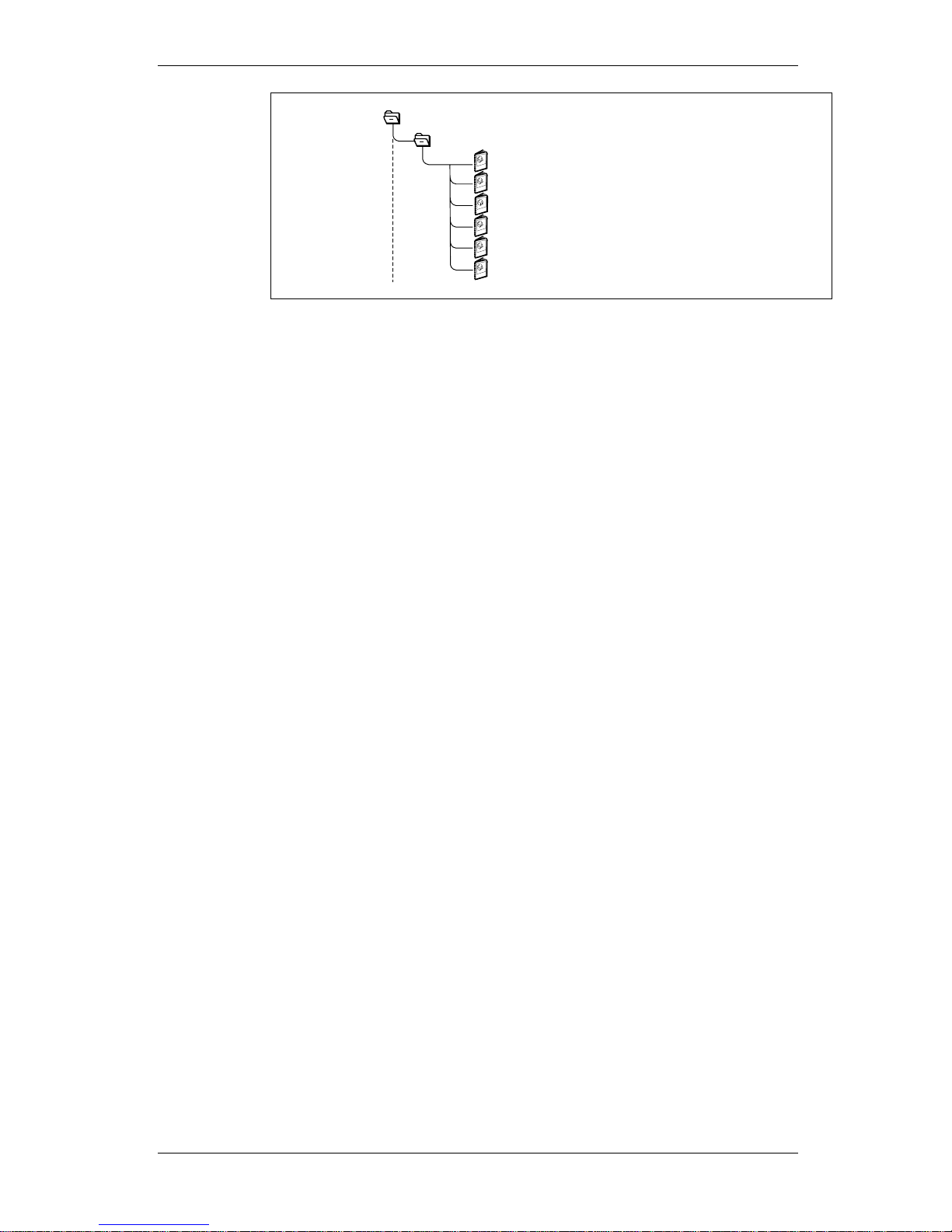
1.3 RBS 2000 Library Overview
The Customer Product Information (CPI) for dTRU based RBS 2000
Macro cabinets consists of the following manuals:
EN/LZT 720 0008 P2A
2001-11-28
15 (485)
© Ericsson Radio Systems AB
— All Rights Reserved —
Preliminary
Page 18
Preface
P007803D
Reference Manual
Installation and Integration Manual
RBS Synchronization Manual
Cabinet Reconfiguration Manual
Maintenance Manual
Spare Parts Catalogue
RBS 2000
RBS 2206 Library
Figure 1 The CPI for Macro 12–TRX cabinets
1.4 How to Order CPI
CPI can be ordered in the same way as all other Ericsson products
using the product number to identify each product. Orders can be
placed through any local Ericsson company, or alternatively, on the
Internet. How operators and customers and Ericsson companies order
CPI is described in detail below.
1.4.1 Outside Ericsson
To place an order for CPI, contact any Ericsson company and follow
the same procedure as with all other Ericsson products.
The most up-to-date CPI can be downloaded from the Extranet by
customers and contractors that have obtained access by visiting
Ericsson’s Extranet e-business site. See access information below.
How to Obtain Access to the Extranet
Access is granted by the Key Account Manager (KAM) from your local
Ericsson company. The Extranet address is:
https://ebusiness.ericsson.net
To be able to access the Extranet site you need to ensure that:
• your company allows access to secure sites (HTTPS) through its
firewall.
• your PC has either Microsoft Internet Explorer 4.01 with SP2 or
later, or Netscape navigator 4.61 or later.
•
your browser has the plug-ins necessary to view or download PDF
and Microsoft office files.
If you are unsure of any of these preconditions, please check with your
local IS/IT Support or help desks within your company.
The Access Process
•
To access the site you must have an individual user name and
password. To request access, send an e-mail to the support centre
asq.ex@era.ericsson.se stating your name, telephone number, email address and with which customer or Ericsson company you
work.
16 (485)
EN/LZT 720 0008 P2A
2001-11-28
© Ericsson Radio Systems AB
— All Rights Reserved —
Preliminary
Page 19

Preface
Once your access is setup, a reply with all the details you need
will be sent to you.
Alternatively, you can download the Portal Order form from the
Extranet.
•
The first time you log in to the site, we recommend you to read
the user instructions.
More information about Extranet can be found at the Extranet address
below. For support on issues related to the Extranet,
Tel.: +46 8 585 33085.
1.4.2 Inside Ericsson
The Intranet is an internal Ericsson web that can only be accessed by
Ericsson personnel.
All CPI products are available on the Intranet at CPI Store:
http://cpistore.ericsson.se
Ericsson personnel, who may require access to CPI while operating
outside Ericsson’s firewall, can get more information about Extranet
access from the following address:
http://inside.ericsson.se/ebusiness/
1.5 R1A to P2A
Table 1
Chapter Chapter Heading Revised Sections
and Subsections
Changes
General
RBS 2106 has been added.
General GSM 800 has been added (valid from BSS
R9).
1
Preface
1.3
Outdoor RBS has been deleted.
1.3 Figure 1 has been updated.
4
Radio Configurations, RBS 2106
and RBS 2206
4.9
Co-Siting with TDMA RBS Using an ASU
has been added.
5
Product Data RBS 2106 New chapter.
10
Unit Description, CXU-10
The table has been updated with 19"
standard.
11
Unit Description, TMA-CM
New chapter.
17
Unit Description, ACCU-02
New chapter.
18 Unit Description, BFU-21 and
BFU-22
New chapter.
20
Unit Description, RBS 2106
Climate Unit
New chapter.
EN/LZT 720 0008 P2A
2001-11-28
17 (485)
© Ericsson Radio Systems AB
— All Rights Reserved —
Preliminary
Page 20

Preface
This page is intentionally left blank
18 (485)
EN/LZT 720 0008 P2A
2001-11-28
© Ericsson Radio Systems AB
— All Rights Reserved —
Preliminary
Page 21

Product Safety Requirements RBS 2000
2 Product Safety Requirements RBS 2000
The purpose of this document is to specify the product safety
requirements for RBS 2000.
2.1 References
73/23/EEC Low Voltage Directive
CAN/CSA-C22.2 No 1-M94
Audio, Video and Similar Electronic Equipment
CAN/CSA-C22.2 No 950-95
Safety of Information Technology Equipment
Including Electrical Business Equipment
EN 60950 Safety of Information Technology Equipment
Including Electrical Business Equipment
IEC 215 Safety requirements for radio transmitting equipment
IEC 529 Classification of degrees of protection provided by
enclosures (IP Code)
IEC 60950 Safety of Information Technology Equipment
Including Electrical Business Equipment
UL 1419 Standard for Professional Video and Audio
Equipment
UL 1950 Safety of Information Technology Equipment
Including Electrical Business Equipment
2.2 Product Safety
This part of the document defines the Electrical, Mechanical, Heat and
Fire Safety Requirements for the Radio Base Station.
General
The RBS is designed to comply with the following International
Standards:
•
73/23/EEC Low Voltage Directive. (To achieve this, the RBS
shall conform to the standards below.)
• EN 60950 "Safety of Information Technology Equipment
Including Electrical Business Equipment".
• The RBS fulfils the requirements in the general IEC 60950
including national differences notified in EN 60950.
• IEC 215 Safety requirements for transmitting equipment.
• The RBS shall be listed by National Recongnized Testing
Laboratory (NRTL).
• The RBS fullfills encapsulation class IP XX according to
IEC 529.
EN/LZT 720 0008 P2A
2001-11-28
19 (485)
© Ericsson Radio Systems AB
— All Rights Reserved —
Preliminary
Page 22

Product Safety Requirements RBS 2000
In addition to this the product fulfills the environmental requirements.
The RBS is so designed and constructed that, under all conditions of
normal use and under a likely fault condition, it protects against
personal injury from electrical shock and other hazards.
The RBS is protected against serious fire originating in the equipment
as well as mechanical hazards in the equipment, as well as mechanical
hazards in the meaning of the applicable standard.
For the US the following standards are applicable:
•
UL 1950 "Safety of Information Technology Equipment Including
Electrical Business Equipment".
For Canada the following standards are applicable:
•
CAN/CSA-C22.2 No 1-M94 Audio, Video and Similar Electronic
Equipment.
2.2.1 Declaration of Conformity
Tests and inspections shall be carried out according to ECMA
requirements.
20 (485)
EN/LZT 720 0008 P2A
2001-11-28
© Ericsson Radio Systems AB
— All Rights Reserved —
Preliminary
Page 23

Environmental Capabilities
3 Environmental Capabilities
3.1 Scope
This chapter covers the environmental requirements for the indoor and
outdoor temperature non-controlled operation conditions. Subjects
covered are: Climatic, Biological, Chemically active substances,
Mechanically active substances and Mechanical conditions.
3.2 Terminology
Definition of concepts:
Normal operation conditions
Environmental conditions where all units shall be able to function as
specified.
Safe function
Environmental stress above the limits for normal operation where all
units shall continue to function during the stress, but performance or
capacity may be reduced.
Reduction of performance or capacity shall be documented as typical
value.
When the environmental stress has dropped to normal operation
conditions, function as specified shall automatically be achieved.
Safe function refers to an operation period of not more than 72
consecutive hours, and a total of not more than 15 days in one year.
Non-destruction
Environmental stress above the limits for safe function during which no
function is guaranteed and performance may degrade in an unspecified
manner.
When the environmental stress has dropped to normal operation
conditions, no manual intervention (on site) is needed to restore full
performance of the RBS.
Non-destruction refers to an operation period of not more than 96
consecutive hours, and a total of not more than 5.5 days in a 3 years
period.
GSM concepts
The GSM concepts for Normal operation and Extreme operation
conditions as defined in GSM 11.20-12.3.2 are both equal to the
Normal condition as defined and used in this document. This means, all
RF parameters are guaranteed within the Normal condition range as
defined in this document.
EN/LZT 720 0008 P2A
2001-11-28
21 (485)
© Ericsson Radio Systems AB
— All Rights Reserved —
Preliminary
Page 24

Environmental Capabilities
3.3 References
IEC 721-3-.. Classification of groups of environmental
parameters and their severities.
ETSI 300 019-1-.. Classification of environmental conditions.
3.4 Transport -40
C - +70
C
3.4.1 General Conditions
The severity of the requirements is in conformity with: IEC 721-3-2
classes 2K4/2B2/2C2/2S2/2M2. and ETS 300 019-1-2 Class 2.3
"PUBLIC transportation".
These requirements are valid for equipped cabinets (excluding batteries).
The values in these conditions are valid for a maximum transport time
of 3 months. The time is measured from the packages are leaving the
shipping store, and includes storing in connection with the transport.
Note: These requirements restrict flight transportation to aircrafts
with pressure cabins. As modern aircrafts have pressure
cabins, these limitations are expected to be only formal.
Note: The severity levels are chosen with equipped cabinets in
mind. Therefore transport of equipment outside the cabinets
can result in extremes. These extremes shall be handled by
its own packing.
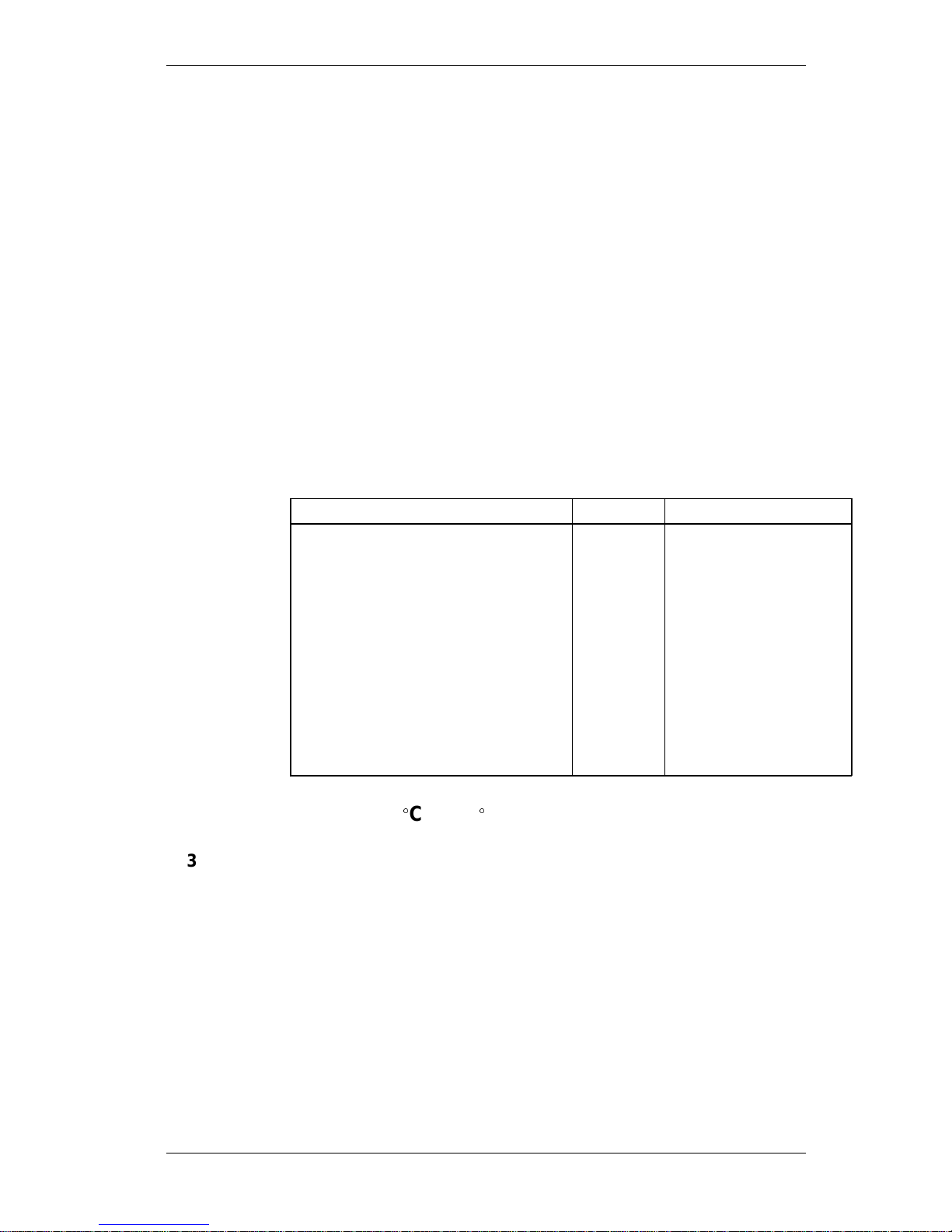
3.4.2 Climatic conditions
During transportation the equipment could be exposed to extremes in
temperature and humidity. The equipment shall be packaged. The
equipment shall be operational after being subjected to the ambient
temperature and humidity stated hereafter.
The severity of these requirements are in conformity with: IEC 721-3-2
class 2K4. and ETS 300 019-1-2 Class 2.3.
Requirements
Table 2
Environmental Parameters Unit Value
Temperature
C
- 40- +70
Relative Humidity % 5-100
3.4.3 Biological conditions.
The severity of these requirements is in conformity with: IEC 721-3-2
class 2B2. and ETS 300 019-1-2 Class 2.3.
3.4.4 Chemically Active Substances.
The severity of these requirements is in conformity with: IEC 721-3-2
class 2C2. and ETS 300 019-1-2 Class 2.3.
22 (485)
EN/LZT 720 0008 P2A
2001-11-28
© Ericsson Radio Systems AB
— All Rights Reserved —
Preliminary
Page 25
Environmental Capabilities
Note: The values are average yearly levels of airborne
contaminants that can be accepted. It is assumed that one of
the contaminants is dominant at each site, and that the other
is present in insignificant amounts.
3.4.5 Mechanically active substances
The severity of these requirements is in conformity with: IEC 721-3-2
class 2S2. and ETS 300 019-1-2 Class 2.3.
3.4.6 Mechanical conditions
The packing and transport method shall be chosen in order not to
expose the equipment to stress beyond these limits. The equipment
shall function as specified when installed after test.
The severity of these requirements is in conformity with: IEC 721-3-2
class 2M2. and ETS 300 019-1-2 Class 2.3.
Requirements
Table 3
Environmental Parameters Unit Value
Vibration sinus:
displacement mm 3.5
acceleration m/s² 10 15
frequency Hz 2-9 9-200 200-500
Random ASD: m2/s
3
1.0
acceleration m/s² 12.0
frequency Hz 2-200
Shock:
peak acceleration m/s² 100
duration ms 11
3.5 Storage -25C - +55
C
3.5.1 General Conditions
The severity of the requirements is in conformity with: IEC 721-3-1
classes 1K4/1Z2/1Z3/1Z5/1B2/1C2/1S3/1M2, and ETS 300 019-1-1
Class 1.2. "WEATHERPROTECTED, not temperature-controlled
storage".
During storage the equipment shall be packaged. The values in these
conditions are valid for a maximum storage time of 12 months. The
time refers to equipment in its outer package and stored at the
consignee in a conditioned store.
3.5.2 Climatic conditions
The equipment shall be shall be in packaged condition.
EN/LZT 720 0008 P2A
2001-11-28
23 (485)
© Ericsson Radio Systems AB
— All Rights Reserved —
Preliminary
Page 26
Environmental Capabilities
The severity of these requirements is in conformity with IEC 721-3-1
classes 1K4/1Z2/1Z3/1Z5. and ETS 300 019-1-1 class 1.2
Requirements
Table 4
Environmental Parameters
Unit Value
Temperature
C
- 25 - +55
Relative Humidity % 10 -100
3.5.3 Biological conditions
The severity of these requirements is in conformity with IEC 721-3-1
class 1B2. and ETS 300 019-1-1 class 1.2
3.5.4 Chemically Active Substances
The severity of these requirements is in conformity with: IEC 721-3-1
class IC2 and ETS 200 019-1-1 Class 1.2.
Note: The values are average yearly levels of airborne
contaminants that can be accepted. It is assumed that one of
the contaminants is dominant at each site, and that the other
is present in insignificant amounts.
3.5.5 Mechanically Active Substances
The severity of these requirements is in conformity with: IEC 721-3-1
class 1S3. and ETS 300 019-1-1 Class 1.2.
3.5.6 Mechanical Conditions
The packing and transport method shall be chosen in order not to
expose the equipment to stress beyond these limits. The equipment
shall function as specified when installed after test.
The severity of these requirements is in conformity with: IEC 721-3-1
class 1M2. and ETS 300 019-1-1 Class 1.2.
Requirements
Table 5
Environmental Parameters Unit Value
Vibration sinus:
displacement mm 3.5
acceleration m/s² 10
frequency Hz 2-9 9 -200
Shock:
peak acceleration m/s² 40
duration ms 22
24 (485)
EN/LZT 720 0008 P2A
2001-11-28
© Ericsson Radio Systems AB
— All Rights Reserved —
Preliminary
Page 27

Environmental Capabilities
3.6 Handling -40C - +70
C
3.6.1 General Conditions
This section refers to shorter periods of transport and storage in
unpacked conditions. Precautions to avoid condensation before
subjecting the equipment to operational conditions are necessary.
3.6.2 Climatic conditions
During handling the equipment withstands the conditions stated in
Section 3.4.2 on page 22 in this document.
3.6.3 Biological conditions.
During Handling the equipment withstands the conditions stated in
Section 3.4.3 on page 22 in this document.
3.6.4 Chemically active substances
During Handling the equipment withstands the conditions stated in
Section 3.4.4 on page 22 in this document.
3.6.5 Mechanically active substances
During Handling the equipment withstands the conditions stated in
Section 3.4.5 on page 23 in this document.
3.6.6 Mechanical conditions
The equipment shall endure stresses normal for handling, during
handling the equipment withstand the conditions stated in Section 3.4.6
on page 23in this document.
3.7 Operation Indoor +5
C - +40
C
3.7.1 General Conditions
The severity of these requirements is in conformity with: IEC 721-3-3
classes 3K3/3Z2/3Z4/3B1/3C2(3C1)/3S2/3M1. and ETS 300 019-1-3
Class 3.1 "TEMPERATURE-controlled locations".
This clause refers to the environment which an RBS for indoor use
shall endure.
Note: The different operating temperature levels according to Safe
function and Non destruction, refer to situations where the
RBS is supposed to have been operating in "normal
condition" mode for a certain time. Then the surrounding
temperature in the compartment increases (decreases)
according to this figures. Accordingly, this means that the
surrounding temperature is allowed to change within the
limits while the RBS still operates and has its own loss of
energy.
EN/LZT 720 0008 P2A
2001-11-28
25 (485)
© Ericsson Radio Systems AB
— All Rights Reserved —
Preliminary
Page 28

Environmental Capabilities
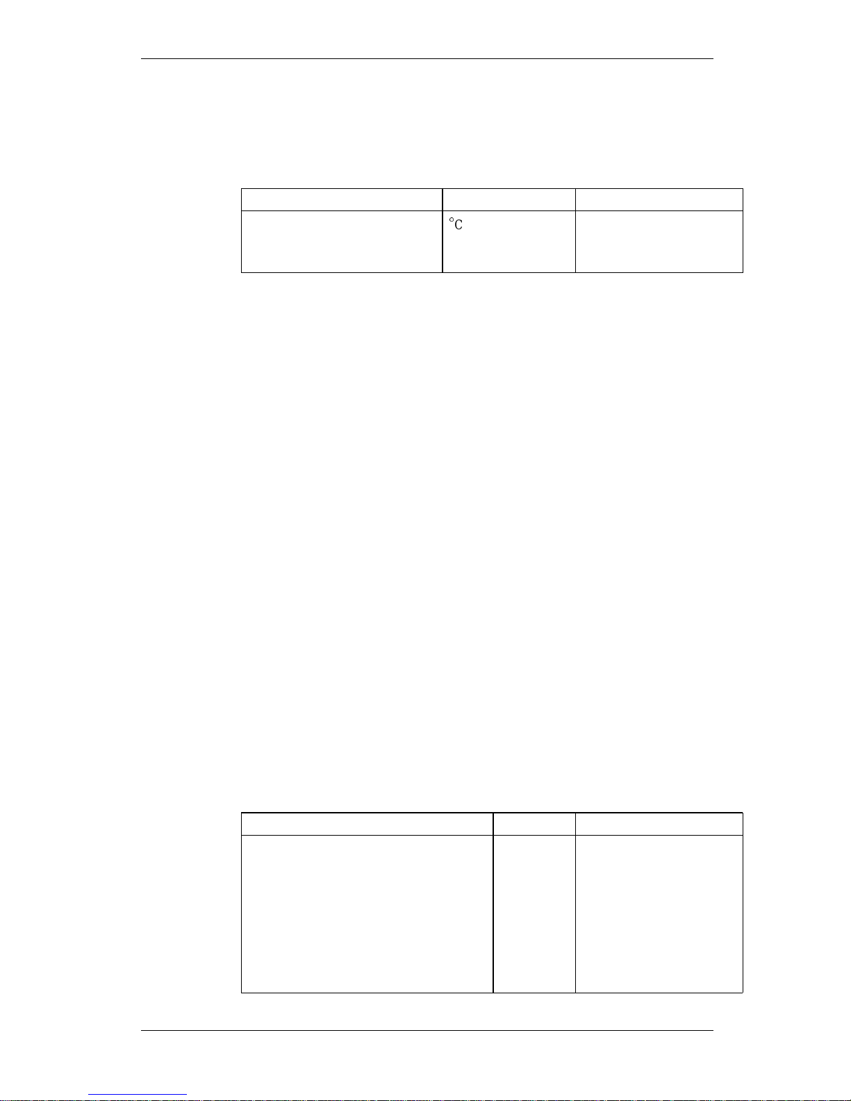
3.7.2 Climatic conditions.
The severity of these requirements are in conformity with: IEC 721-3-3
classes 3K3/3Z2/3Z4. and ETS 300 019-1-3 Class 3.1.
Table 6
Environmental Unit Value
Parameters Normal
Condition
Safe funct. Non Destr.
Temperature
C
+5- +40 0 - +45 -10 - +55
Relative Humidity % 5-85 5-90 5-90
3.7.3 Biological conditions
Requirements
There are no requirements for this condition.
3.7.4 Chemically active substances
The severity of these requirements is in conformity with: IEC 721-3-3
classes /3C2(3C1)/. and ETS 300 019-1-3 Class 3.1.
Note: The values are average yearly levels of airborne
contaminants that can be accepted. It is assumed that one of
the contaminants is dominant at each site, and that the other
is present in insignificant amounts.
3.7.5 Mechanically active substances
The severity of these requirements is in conformity with: IEC 721-3-3
class /3S2/. and ETS 300 019-1-3 Class 3.1.
3.7.6 Mechanical conditions
The severity of these requirements is in conformity with: IEC 721-3-3
class/3MI/. and ETS 300 019-1-3 class 3.1.
26 (485)
EN/LZT 720 0008 P2A
2001-11-28
© Ericsson Radio Systems AB
— All Rights Reserved —
Preliminary
Page 29

Environmental Capabilities
Table 7
Environmental Parameters Unit Value
Vibration sinus:
displacement mm 0.6
acceleration m/s² 2
frequency Hz 2-9 9 -200
Vibration random:
ASD m
2/s3
0.1
1)
ASD m2/s
3
0.2
2)
acceleration m/s² 3.8
1)
acceleration m/s² 5.4
2)
frequency Hz 2-200
Shock:
peak acceleration m/s² 40
3)
duration ms 11
1)
Safe function
2)
Non destruction
3)
This requirement belongs to ’Safe function’ with the exemption:
performance of the RBS shall be verified as ’no loss of calls
Seismic Exposure
The complete equipped RBS shall be tested for seismic exposure.
Deviations shall be reported.
Safe function during seismic exposure. Deviations shall be reported.
Table 8
Test frequency range 1-15 Hz
Required Response Spectrum RRS
Shape of RRS as IEC fig 3
Number of time scale histories 1/ testing direction
Duration of time scale histories 35 s
Number of testing directions 3
If necessary there are possibilities to equip the RBS with an optional
Seismic Exposure protection device.
3.8 Operation Outdoor -33C - +40C
This Environmental class corresponds in full to ’Operation Outdoor
-33
C - +45C’ with the exception of the upper temperature limit.
EN/LZT 720 0008 P2A
2001-11-28
27 (485)
© Ericsson Radio Systems AB
— All Rights Reserved —
Preliminary
Page 30
Environmental Capabilities
3.9 Operation Outdoor -33C - +45
C
The severity of the requirements is in conformity with: IEC 721-3-4
classes 4K2/4Z5/4Z7/4B1/4C2(4C3)/4S2/4M5. and ETS 300 019-1-4
Class 4.1. "NON-WEATHERPROTECTED location", except for the
temperature range which is extended to +45
C.
This clause refers to the environment which an RBS for outdoor
non-weather protected location shall endure.
The figures below refers to the environment that is surrounding the
cabinet and the temperature is the shaded air temperature.
3.9.1 Climatic Conditions
The severity of these requirements is in conformity with: IEC 721-3-4
classes 4K2/4Z5/4Z7. and ETS 300 019-1-4 Class 4.1. In addition to
this Ericsson demands more rigorous values than stated by IEC and
ETSI above.
The RBS shall be designed for a power loss of max. 48 hours. This
applies both to installation and operation.
Table 9
Environmental Unit Value
Parameters Normal Condition Non Destr.
Temperature
C
-33 - +45 -40 - +70
Relative Humidity % 15 - 100 15 - 100
3.9.2 Biological Conditions
The severity of these requirements is in conformity with: IEC 721-3-4
class /4B1/. and ETS 300 019-1-4 Class 4.1.
3.9.3 Chemically Active Substances
The severity of these requirements is in conformity with: IEC 721-3-4
classes /4C2(4C1)/. and ETS 300 019-1-4 Class 4.1.
Note: The values are average yearly levels of airborne
contaminants that can be accepted. It is assumed that one of
the contaminants is dominant at each site, and that the other
is present in insignificant amounts.
3.9.4 Mechanically Active Substances
The severity of these requirements is in conformity with: IEC 721-3-4
class /4S2/. and ETS 300 019-1-4 Class 4.1.
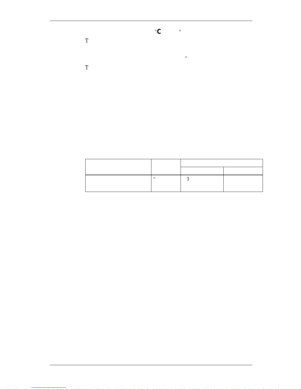
3.9.5 Mechanical Conditions
The severity of these requirements are in conformity with: IEC 721-3-4
class /4M5/. and ETS 300 019-1-4 Class 4.1.
28 (485)
EN/LZT 720 0008 P2A
2001-11-28
© Ericsson Radio Systems AB
— All Rights Reserved —
Preliminary
Page 31

Environmental Capabilities
Table 10
Environmental Parameters Unit Value
Vibration sinus:
displacement mm 0.6
acceleration m/s² 2
frequency Hz 2-9 9 -200
no. of sweep cycles 5
no. of test directions 3
testing method IEC 68-2-6
Vibration random:
ASD m
2/s3
0.1
1)
ASD m2/s
3
0.2
2)
acceleration m/s² 3.8
1)
acceleration m/s² 5.4
2)
frequency Hz 2-200
testing method IEC
68-2-64
Shock: <100 kg >100 kg
peak acceleration m/s² 250 100
3)
duration ms 66
pulse shape half sine
no. of shock pulses 500 per
direction
no. of test directions 6
testing method IEC
68-2-27
1)
Safe function
2)
Non destruction
3)
These requirements belong to ’Safe function’ with the exemption:
performance of the RBS shall be verified as ’no loss of calls’
Seismic Exposure
The complete equipped RBS shall be tested for seismic exposure.
Deviations shall be reported.
Safe function during seismic exposure. Deviations shall be reported.
EN/LZT 720 0008 P2A
2001-11-28
29 (485)
© Ericsson Radio Systems AB
— All Rights Reserved —
Preliminary
Page 32

Environmental Capabilities
Table 11
Test frequency range 1-15 Hz
Required Response Spectrum RRS
Shape of RRS as IEC fig 3
Number of time scale histories 1/ testing direction
Duration of time scale histories 35 s
Number of testing directions 3
There are possibilities to equip the RBS with an optional Seismic
Exposure protection device.
3.10 Operation Outdoor -33C - +55
C
This Environmental class corresponds in full to ’Operation Outdoor
-33
C - +45
C’ with the exception of the upper temperature limit.
3.11 Operation Mast Mounted Equipment -33
C - +45
C
This Environmental class corresponds to ’Operation Outdoor -33
C-
+45
C’ with the exceptions stated below.
Table 12
Environmental Parameters Unit Value
Normal Cond. Non destruct.
Temperature
C
-33 - +45 -40 - +70
Change of temperature
C/min
6 6
Vibration sinus:
displacement mm 3.0
acceleration m/s
2
10
frequency Hz 2-9 9 - 200
Vibration random:
ASD m2/s
3
0.5
frequency Hz 2 - 200
duration of
exposure
min 30
no. of test
directions
Hz 3
Fauna none Not Appl. Not Appl.
3.12 Operation Mast Mounted Equipment -33
C - +55C
This Environmental class corresponds to ’Operation Outdoor -33
C-
+55
C’ with the exceptions stated below.
30 (485)
EN/LZT 720 0008 P2A
2001-11-28
© Ericsson Radio Systems AB
— All Rights Reserved —
Preliminary
Page 33

Environmental Capabilities
Table 13
Environmental Parameters Unit Value
Normal Cond. Non destruct.
Temperature
C
-33 - +55 -40 - +70
Relative humidity % 5 - 100 5 - 100
Absolute humidity g/m
3
0.26 -40 0.26 - 40
Change of temperature
C/min
6 6
Rain temperature
C
5 5
Vibration sinus:
displacement mm 3
acceleration m/s
2
10
frequency Hz 2-9 9 - 200
Vibration random:
ASD m2/s
3
0.5 0.2
frequency Hz 2 - 200 200 - 500
Shock:
peak acc. m/s
2
100
1)
duration ms 11
Fauna none Not Appl. Not Appl.
1)
The requirements belong to ’Safe function’ with the exemption:
performance of the RBS shall be verified as ’no loss of calls’
EN/LZT 720 0008 P2A
2001-11-28
31 (485)
© Ericsson Radio Systems AB
— All Rights Reserved —
Preliminary
Page 34

Environmental Capabilities
This page is intentionally left blank
32 (485)
EN/LZT 720 0008 P2A
2001-11-28
© Ericsson Radio Systems AB
— All Rights Reserved —
Preliminary
Page 35

Radio Configurations, RBS 2106 and RBS 2206
4 Radio Configurations, RBS 2106 and
RBS 2206
This chapter describes the dTRU-based radio configurations and their
performance. Note that the GSM 800 configurations are valid from
BSS R9.
4.1 Introduction
4.1.1 Mobile Telephone System
Figure 2 RBS 2000 in the Ericsson GSM system
The Base Station System (BSS) contains two functional entities: the
Base Station Controller (BSC) and the Base Transceiver Station (BTS).
The BSC handles radio-related functions, such as handover,
management of the radio network resources, and cell configuration data.
It also controls radio frequency power levels in RBSs and MSs.
The BTS is a network component which serves one cell and is
controlled by the BSC. The BTS contains a number of transceivers. It
consists of the radio transceivers and all the digital signal processing
equipment. RBS 2000 contains equipment for 1 - 3 BTSs.
EN/LZT 720 0008 P2A
2001-11-28
33 (485)
© Ericsson Radio Systems AB
— All Rights Reserved —
Preliminary
Page 36

Radio Configurations, RBS 2106 and RBS 2206
Figure 3 An example of an RBS 2000 servicing a three-cell site
4.1.2 Radio Base Station
The Radio Base Station 2000 (RBS 2000) is Ericsson’s second
generation of RBSs developed to meet the GSM specifications for BTSs.
4.2 References
GSM:05.05 GSM Requirements 05.05 phase 2+ Radio
Transmission and Reception.
GSM:05.08 GSM Requirements 05.08 phase 2+ Radio
Subsystem Link Control.
4.3 Definitions
Tower Mounted Amplifier (TMA)
The TMA compensates for signal loss in the receiver antenna cables,
reduces system noise and improves uplink sensitivity. The TMA can
consist of a duplex filter. Duplex is the function that allows
communication in two directions (sending and receiving) on one
channel.
The TMA used for 12 TRX products is Dual Duplex TMA (ddTMA).
Some configurations can use a TMA designed for reception only
(rTMA).
Antenna Reference Point
The antenna reference point is the point where the radio signal crosses
the RBS border, that is, the connector for the antenna feeder. See the
figure below.
34 (485)
EN/LZT 720 0008 P2A
2001-11-28
© Ericsson Radio Systems AB
— All Rights Reserved —
Preliminary
Page 37

Radio Configurations, RBS 2106 and RBS 2206
Note: The TMA is inside the RBS border.
X
P007531A
RBS
TRX
Combining
system
+
filtering
TRX
TRX
X = Antenna reference point
Antenna
.
.
.
Figure 4 Antenna reference point
Antenna System
The antenna system is constituted by all RF transmission and reception
antennas, directed to cover the same area or multi-casting configurations.
Antenna Sharing Unit (ASU)
An ASU is a unit used for sharing RX antennas between RBSs.
Base Transceiver Station (BTS)
A BTS is a unit operating on a set of frequencies in one cell.
Basic Configuration
A basic configuration is a specified set of transceivers, CDUs, and in
some cases, TMAs, connected to one antenna system.
A basic configuration can be multiplied or used in combination with
other basic configurations to build the needed site equipment.
Variations of a basic configuration may exist, differing in cable lengths.
This depends on factors such as implementation in different cabinets.
Radio Base Station (RBS)
An RBS is all equipment in an Ericsson base station, and may be
comprised of several BTSs.
Each RBS has one DXU, controlling a maximum of 12 TRXs.
Site Cell Configuration (SCC)
The SCC is a geographical concept describing how an area around one
RBS site is divided into radio traffic areas. The following types of site
are defined:
Omni-site Radio coverage in one 360 degree sector,
that is in one area, using one BTS.
EN/LZT 720 0008 P2A
2001-11-28
35 (485)
© Ericsson Radio Systems AB
— All Rights Reserved —
Preliminary
Page 38

Radio Configurations, RBS 2106 and RBS 2206
2–sector site Radio coverage in two sectors, that is two
distinct areas, using two BTSs.
3–sector site Radio coverage in three sectors, that is
three distinct areas, using three BTSs.
4.3.1 Cabinet Types
RBS 2106 Outdoor cabinet with a maximum of six
dTRUs/12 TRXs per cabinet
RBS 2206 Indoor cabinet with a maximum of six
dTRUs/12 TRXs per cabinet
4.3.2 Configurations Identity
The figure below shows how a basic configuration identity is
constructed.
Variant indication, lower case letter a-z
Number of used transceivers
Max number of transceivers
Number of antennas
dd TMA used
Hybrid in dTRU; used
Modified frequency band
Duplexer in CDU; used
Frequency band
CDU-type
P007365A
G9deht_3.6(5)\a
Figure 5 Basic configuration identity
4.4 Frequency Bands
GSM 800 Uplink: 824 - 849 MHz
Downlink: 869 - 894 MHz
P-GSM 900 Uplink: 890 – 915 MHz
Downlink: 935 – 960 MHz
E-GSM 900 Uplink: 880 – 915 MHz
Downlink: 925 – 960 MHz
GSM 1800 Uplink: 1710 – 1785 MHz
36 (485)
EN/LZT 720 0008 P2A
2001-11-28
© Ericsson Radio Systems AB
— All Rights Reserved —
Preliminary
Page 39

Radio Configurations, RBS 2106 and RBS 2206
Downlink: 1805 – 1880 MHz
GSM 1900 Uplink: 1850 – 1910 MHz
Downlink: 1930 – 1990 MHz
These frequency bands are supported by the configurations described in
this chapter.
4.5 Basic Configurations
The GSM 800, GSM 900, GSM 1800 and GSM 1900 configurations
meet the GSM requirements, except where otherwise stated.
The capacity of a configuration is defined at the TX and RX antenna
reference points at the RBS border. There is an X close to every
reference point in the following figures. The RBS border is not
included in the figures.
The equivalent output power with SW power boost (TX diversity)
configured is the original output power specified for the basic
configuration increased with typically 3 dB, if separate TX antennas are
used. The configurations that support SW power boost are listed in
Section 4.6.3 on page 77.
Functional views of radio signal paths for various configurations are
shown in Figure 6 on page 38 upto and including Figure 24 on page 66.
Only components necessary to illustrate the configuration are shown.
In some configurations, the radio signal paths can differ depending on
where in the cabinet the basic configuration is used. The figures show
fully-equipped cabinets with two or three BTSs, that is two or three
basic configurations are shown in the same figure. These are different
physical implementations of the same basic configuration, not different
configurations. The second BTS is drawn with dotted lines to show
how an SCC in a fully-equipped cabinet is connected.
4.5.1 dTRU Topology
Configuration of Hybrid Combiner
The dTRU can be configured with or without the hybrid combiner,
using two external cables.
RX Signals Distributed from Two Ports
The RX signals can be distributed from the RX1 and RX2 ports to all
four receivers when both transceivers are connected to the same antenna
system.
EN/LZT 720 0008 P2A
2001-11-28
37 (485)
© Ericsson Radio Systems AB
— All Rights Reserved —
Preliminary
Page 40

Radio Configurations, RBS 2106 and RBS 2206
TX1
TX
TX
P007394B
HC2
Hybrid
combiner
TX2
TX1+TX2
HC1
RX
RX
RX
RX
RX3
RX4
TX
TX
RX1
RX
RX
RX
RX
RX2
TX1
TX
TX
HC2
Hybrid
combiner
RX2
TX2
TX1+TX2
HC1
RX
RX
RX
RX
RX1
RX4
RX3
RX
RX
RX
RX
dTRU with no hybrid
combiner in use
dTRU with hybrid
combiner in use
Figure 6 dTRU with and without hybrid combiner in use
38 (485)
EN/LZT 720 0008 P2A
2001-11-28
© Ericsson Radio Systems AB
— All Rights Reserved —
Preliminary
Page 41

Radio Configurations, RBS 2106 and RBS 2206
4.5.2 CDU-F Configurations
Basic Configuration F9de_2.4 and F18d_2.4
TX1
RX1
RX2
TX2
TX1
dTRU
TX1
TX2
TX1
TX2
RX1
dTRU
CDU-F
DPX
FCOMB
FCOMB
RX2
TX2
CXU
RX1
RX2
LNA
LNA
TX/
RXA
Ant.
RXB
P007376A
X
X
Figure 7 F9de_2.4 and F18d_2.4
Characteristics
Number of CDUs 1
Frequency band E-GSM (F9de_2.4)
GSM 1800 (F18d_2.4)
Max. number of TRXs 4
Number of feeders 2
Number of antennas 2
Antenna configuration TX/RX + RX
EN/LZT 720 0008 P2A
2001-11-28
39 (485)
© Ericsson Radio Systems AB
— All Rights Reserved —
Preliminary
Page 42

Radio Configurations, RBS 2106 and RBS 2206
Basic Configuration F9det_2.4 and F18dt_2.4
TX1
RX1
RX2
TX2
TX1
dTRU
TX1
TX2
TX1
TX2
RX1
dTRU
CDU-F
DPX
FCOMB
FCOMB
RX2
TX2
CXU
RX1
RX2
LNA
LNA
TX/
RXA
Ant.
P007377A
X
DPX
DPX
LNA
X
DPX
DPX
LNA
RXB
Figure 8 F9det_2.4 and F18dt_2.4
Characteristics
Number of CDUs 1
Frequency band E-GSM (F9det_2.4)
GSM 1800 (F18dt_2.4)
Max. number of TRXs 4
Number of feeders 2
Number of antennas 2
Antenna configuration TX/RX + RX
TMA configuration ddTMA + ddTMA or
ddTMA + rTMA
40 (485)
EN/LZT 720 0008 P2A
2001-11-28
© Ericsson Radio Systems AB
— All Rights Reserved —
Preliminary
Page 43

Radio Configurations, RBS 2106 and RBS 2206
Basic Configuration F9de_2.6 and F18d_2.6
P007378A
TX1
RX1
RX2
TX2
TX1
dTRU
TX1
TX2
TX1
TX2
RX1
dTRU
CDU-F
DPX
FCOMB
RX2
TX2
RX1
RX2
LNA
LNA
TX/
RXA
Ant.
RXB
X
X
TX1
RX1
RX2
TX2
TX1
dTRU
RX1
dTRU
RX2
TX2
BTS2
BTS1
TX1
TX2
TX1
TX2
CDU-F
FCOMB
TX1
RX1
RX2
TX2
TX1
dTRU
TX1
TX2
TX1
TX2
RX1
dTRU
CDU-F
DPX
FCOMB
RX2
TX2
CXU
RX1
RX2
LNA
LNA
TX/
RXA
Ant.
RXB
X
X
FCOMB
FCOMB
FCOMB
Figure 9 F9de_2.6 and F18d_2.6
EN/LZT 720 0008 P2A
2001-11-28
41 (485)
© Ericsson Radio Systems AB
— All Rights Reserved —
Preliminary
Page 44

Radio Configurations, RBS 2106 and RBS 2206
Characteristics
Number of CDUs 2*
Frequency band E-GSM (F9de_2.6)
GSM 1800 (F18d_2.6)
Max. number of TRXs 6
Number of feeders 2
Number of antennas 2
Antenna configuration TX/RX + RX
* Three CDU-Fs support two sectors.
Note: The second BTS is only shown to illustrate a 2 x 6
configuration. BTS1 and BTS2 are two different physical
implementations of the same basic configuration.
42 (485)
EN/LZT 720 0008 P2A
2001-11-28
© Ericsson Radio Systems AB
— All Rights Reserved —
Preliminary
Page 45

Radio Configurations, RBS 2106 and RBS 2206
Basic Configuration F9det_2.6 and F18dt_2.6
P007379A
TX1
RX1
RX2
TX2
TX1
dTRU
TX1
TX2
TX1
TX2
RX1
dTRU
CDU-F
DPX
FCOMB
RX2
TX2
RX1
RX2
LNA
LNA
TX1
RX1
RX2
TX2
TX1
dTRU
RX1
dTRU
RX2
TX2
BTS2
BTS1
TX1
TX2
TX1
TX2
CDU-F
FCOMB
FCOMB
TX1
RX1
RX2
TX2
TX1
dTRU
TX1
TX2
TX1
TX2
RX1
dTRU
CDU-F
DPX
FCOMB
RX2
TX2
CXU
RX1
RX2
LNA
LNA
TX/
RXA
X
DPX
DPX
LNA
X
DPX
DPX
LNA
RXB
TX/
RXA
X
DPX
DPX
LNA
X
DPX
DPX
LNA
RXB
FCOMB
FCOMB
Figure 10 F9det_2.6 and F18dt_2.6
EN/LZT 720 0008 P2A
2001-11-28
43 (485)
© Ericsson Radio Systems AB
— All Rights Reserved —
Preliminary
Page 46

Radio Configurations, RBS 2106 and RBS 2206
Characteristics
Number of CDUs 2*
Frequency band E-GSM (F9det_2.6)
GSM 1800 (F18dt_2.6)
Max. number of TRXs 6
Number of feeders 2
Number of antennas 2
Antenna configuration TX/RX + RX
TMA configuration ddTMA + ddTMA or
ddTMA + rTMA
* Three CDU-Fs support two sectors.
Note: The second BTS is only shown to illustrate a 2 x 6
configuration. BTS1 and BTS2 are two different physical
implementations of the same basic configuration.
44 (485)
EN/LZT 720 0008 P2A
2001-11-28
© Ericsson Radio Systems AB
— All Rights Reserved —
Preliminary
Page 47

Radio Configurations, RBS 2106 and RBS 2206
Basic Configuration F9de_2.8 and F18d_2.8
TX1
RX1
RX2
TX2
TX1
dTRU
TX1
TX2
TX1
TX2
RX1
dTRU
CDU-F
DPX
FCOMB
FCOMB
RX2
TX2
CXU
RX1
LNA
TX/
RXB
P007380A
X
TX1
RX1
RX2
TX2
TX1
dTRU
TX1
TX2
TX1
TX2
RX1
dTRU
CDU-F
DPX
FCOMB
FCOMB
RX2
TX2
RX1
LNA
TX/
RXA
Ant.
X
Figure 11 F9de_2.8 and F18d_2.8
EN/LZT 720 0008 P2A
2001-11-28
45 (485)
© Ericsson Radio Systems AB
— All Rights Reserved —
Preliminary
Page 48

Radio Configurations, RBS 2106 and RBS 2206
Characteristics
Number of CDUs 2
Frequency band E-GSM (F9de_2.8)
GSM 1800 (F18d_2.8)
Max. number of TRXs 8
Number of feeders 2
Number of antennas 2
Antenna configuration TX/RX + TX/RX
46 (485)
EN/LZT 720 0008 P2A
2001-11-28
© Ericsson Radio Systems AB
— All Rights Reserved —
Preliminary
Page 49

Radio Configurations, RBS 2106 and RBS 2206
Basic Configuration F9det_2.8 and F18dt_2.8
TX1
RX1
RX2
TX2
TX1
dTRU
TX1
TX2
TX1
TX2
RX1
dTRU
CDU-F
DPX
FCOMB
FCOMB
RX2
TX2
CXU
RX1
LNA
P007381A
TX1
RX1
RX2
TX2
TX1
dTRU
TX1
TX2
TX1
TX2
RX1
dTRU
CDU-F
DPX
FCOMB
FCOMB
RX2
TX2
RX1
LNA
Ant.
TX/
RXB
X
DPX
DPX
LNA
Ant.
TX/
RXA
X
DPX
DPX
LNA
Figure 12 F9det_2.8 and F18dt_2.8
EN/LZT 720 0008 P2A
2001-11-28
47 (485)
© Ericsson Radio Systems AB
— All Rights Reserved —
Preliminary
Page 50

Radio Configurations, RBS 2106 and RBS 2206
Characteristics
Number of CDUs 2
Frequency band E-GSM (F9det_2.8)
GSM 1800 (F18dt_2.8)
Max. number of TRXs 8
Number of feeders 2
Number of antennas 2
Antenna configuration TX/RX + TX/RX
TMA configuration ddTMA + ddTMA
48 (485)
EN/LZT 720 0008 P2A
2001-11-28
© Ericsson Radio Systems AB
— All Rights Reserved —
Preliminary
Page 51

Radio Configurations, RBS 2106 and RBS 2206
Basic Configuration F9de_2.12 and F18d_2.12
TX1
RX1
RX2
TX2
TX1
dTRU
TX1
TX2
TX1
TX2
RX1
dTRU
CDU-F
DPX
FCOMB
FCOMB
RX2
TX2
RX1
LNA
TX/
RXA
Ant.
X
P007382A
TX1
RX1
RX2
TX2
TX1
dTRU
RX1
dTRU
RX2
TX2
TX1
TX2
TX1
TX2
CDU-F
FCOMB
FCOMB
TX1
RX1
RX2
TX2
TX1
dTRU
TX1
TX2
TX1
TX2
RX1
dTRU
CDU-F
DPX
FCOMB
FCOMB
RX2
TX2
CXU
RX1
LNA
TX/
RXA
Ant.
X
Figure 13 F9de_2.12 and F18d_2.12
EN/LZT 720 0008 P2A
2001-11-28
49 (485)
© Ericsson Radio Systems AB
— All Rights Reserved —
Preliminary
Page 52

Radio Configurations, RBS 2106 and RBS 2206
Characteristics
Number of CDUs 3
Frequency band E-GSM (F9de_2.12)
GSM 1800 (F18d_2.12)
Max. number of TRXs 12
Number of feeders 2
Number of antennas 2
Antenna configuration TX/RX + TX/RX
50 (485)
EN/LZT 720 0008 P2A
2001-11-28
© Ericsson Radio Systems AB
— All Rights Reserved —
Preliminary
Page 53

Radio Configurations, RBS 2106 and RBS 2206
Basic Configuration F9det_2.12 and F18dt_2.12
P007383A
TX1
RX1
RX2
TX2
TX1
dTRU
TX1
TX2
TX1
TX2
RX1
dTRU
CDU-F
DPX
FCOMB
FCOMB
RX2
TX2
RX1
LNA
TX1
RX1
RX2
TX2
TX1
dTRU
RX1
dTRU
RX2
TX2
CDU-F
FCOMB
FCOMB
TX1
RX1
RX2
TX2
TX1
dTRU
TX1
TX2
TX1
TX2
RX1
dTRU
CDU-F
DPX
FCOMB
FCOMB
RX2
TX2
CXU
RX1
LNA
Ant.
TX/
RXA
X
DPX
DPX
LNA
TX/
RXB
X
DPX
DPX
LNA
Ant.
TX1
TX2
TX1
TX2
Figure 14 F9de_2.12 and F18dt_2.12
EN/LZT 720 0008 P2A
2001-11-28
51 (485)
© Ericsson Radio Systems AB
— All Rights Reserved —
Preliminary
Page 54

Radio Configurations, RBS 2106 and RBS 2206
Characteristics
Number of CDUs 3
Frequency band E-GSM (F9det_2.12)
GSM 1800 (F18dt_2.12)
Max. number of TRXs 12
Number of feeders 2
Number of antennas 2
Antenna configuration TX/RX + TX/RX
TMA configuration ddTMA + ddTMA
4.5.3 CDU-G Configurations
Basic Configuration G8d_2.2, G9de_2.2, G18d_2.2 and G19d_2.2
TX1
RX1
RX2
TX2
dTRU
TX1
RX1
TX2
CDU-G
DPX
CXU
LNA
TX/
RXA
Ant.
P007384B
DPX
TX/
RXB
RX2
LNA
X
X
ASU
Ant S1(3,5)
Ant S2(4,6)
Figure 15 Gd8_2.2, G9de_2.2, G18d_2.2 and G19d_2.2
Characteristics
Number of CDUs 1
Frequency band GSM 800 (G8d_2.2)
E-GSM (G9de_2.2)
GSM 1800 (G18d_2.2)
GSM 1900 (G19d_2.2)
Max. number of TRXs 2
Number of feeders 2
Number of antennas 2
Antenna configuration TX/RX + TX/RX
52 (485)
EN/LZT 720 0008 P2A
2001-11-28
© Ericsson Radio Systems AB
— All Rights Reserved —
Preliminary
Page 55

Radio Configurations, RBS 2106 and RBS 2206
Note: The ASU is optional equipment.
Basic Configuration G8dt_2.2, G9det_2.2, G18dt_2.2 and G19dt_2.2
TX1
RX1
RX2
TX2
dTRU
TX1
RX1
TX2
CDU-G
DPX
CXU
LNA
TX/
RXA
Ant.
P007385B
DPX
TX/
RXB
RX2
LNA
X
X
ASU
Ant S1(3,5)
Ant S2(4,6)
DPX LNA DPX
DPX LNA DPX
ddTMA
Figure 16 G8dt_2.2, G9det_2.2, G18dt_2.2 and G19dt_2.2
Characteristics
Number of CDUs 1
Frequency band GSM 800 (G8dt_2.2)
E-GSM (G9det_2.2)
GSM 1800 (G18dt_2.2)
GSM 1900 (G19dt_2.2)
Max. number of TRXs 2
Number of feeders 2
Number of antennas 2
Antenna configuration TX/RX + TX/RX
Note: The ASU is optional equipment.
EN/LZT 720 0008 P2A
2001-11-28
53 (485)
© Ericsson Radio Systems AB
— All Rights Reserved —
Preliminary
Page 56

Radio Configurations, RBS 2106 and RBS 2206
Basic Configuration G8dh_2.4, G9deh_2.4, G18dh_2.4 and G19dh_2.4
P007386B
Ant S1(3,5)
Ant S2(4,6)
TX1+TX2
RX1
RX2
dTRU
TX1
RX1
CDU-G
DPX
CXU
LNA
DPX
RX2
LNA
TX1+
TX2
RX1
RX2
dTRU
TX2
TX/
RXA
Ant.
X
TX/
RXB
X
ASU
Figure 17 G8dh_2.4, G9deh_2.4, G18dh_2.4 and G19dh_2.4
Characteristics
Number of CDUs 1
Frequency band GSM 800 (G8dh_2.4)
E-GSM (G9deh_2.4)
GSM 1800 (G18dh_2.4)
GSM 1900 (G19dh_2.4)
Max. number of TRXs 4
Number of feeders 2
Number of antennas 2
Antenna configuration TX/RX + TX/RX
Note: The ASU is optional equipment.
54 (485)
EN/LZT 720 0008 P2A
2001-11-28
© Ericsson Radio Systems AB
— All Rights Reserved —
Preliminary
Page 57

Radio Configurations, RBS 2106 and RBS 2206
Basic Configuration G8dht_2.4, G9deht_2.4, G18dht_2.4 and G19dht_2.4
P007387B
TX/
RXA
Ant.
TX/
RXB
X
X
DPX LNA DPX
Ant S1(3,5)
Ant S2(4,6)
TX1+TX2
RX1
RX2
dTRU
TX1
RX1
CDU-G
DPX
CXU
LNA
DPX
RX2
LNA
TX1+
TX2
RX1
RX2
dTRU
TX2
ASU
DPX LNA DPX
ddTMA
Figure 18 G8dht_2.4, G9deht_2.4, G18dht_2.4 and G19dht_2.4
Characteristics
Number of CDUs 1
Frequency band GSM 800 (G8dht_2.4)
E-GSM (G9deht_2.4)
GSM 1800 (G18dht_2.4)
GSM 1900 (G19dht_2.4)
Max. number of TRXs 4
Number of feeders 2
Number of antennas 2
Antenna configuration TX/RX + TX/RX
Note: The ASU is optional equipment.
EN/LZT 720 0008 P2A
2001-11-28
55 (485)
© Ericsson Radio Systems AB
— All Rights Reserved —
Preliminary
Page 58

Radio Configurations, RBS 2106 and RBS 2206
Basic Configuration G8dh_3.6, G9deh_3.6, G18dh_3.6 and G19dh_3.6
TX1+TX2
RX1
RX2
dTRU
TX1
RX1
CDU-G
DPX
LNA
TX/
RXA
Ant.
DPX
TX/
RXB
RX2
LNA
TX1+
TX2
RX1
RX2
dTRU
TX2
TX1+
TX2
RX1
RX2
dTRU
TX1
CDU-G
DPX
LNA
TX
Ant.
DPX
TX
LNA
RX1
RX2
dTRU
TX2
TX1+
TX2
RX1
RX2
dTRU
TX1
RX1
CDU-G
DPX
CXU
LNA
TX/
RXA
Ant.
DPX
TX/
RXB
RX2
LNA
TX1+
TX2
RX1
RX2
dTRU
TX2
BTS2
BTS1
TX1+
TX2
X
X
X
X
X
X
P007388B
Ant S1
Ant S6
Ant S2
Ant S5
ASU
Figure 19 G8dh_3.6, G9deh_3.6, G18dh_3.6 and G19dh_3.6
56 (485)
EN/LZT 720 0008 P2A
2001-11-28
© Ericsson Radio Systems AB
— All Rights Reserved —
Preliminary
Page 59

Radio Configurations, RBS 2106 and RBS 2206
Characteristics
Number of CDUs 2*
Frequency band GSM 800 (G8dh_3.6)
E-GSM (G9deh_3.6)
GSM 1800 (G18dh_3.6)
GSM 1900 (G19dh_3.6)
Max. number of TRXs 6
Number of feeders 3
Number of antennas 3
Antenna configuration TX/RX + TX/RX + TX
* Three CDU-Fs support two sectors.
Note: The second BTS is only shown to illustrate a 2 x 6
configuration. BTS1 and BTS2 are two different physical
implementations of the same basic configuration.
Note: The ASU is optional equipment.
EN/LZT 720 0008 P2A
2001-11-28
57 (485)
© Ericsson Radio Systems AB
— All Rights Reserved —
Preliminary
Page 60

Radio Configurations, RBS 2106 and RBS 2206
Basic Configuration G8dht_3.6, G9deht_3.6, G18dht_3.6 and G19dht_3.6
TX
TX1+TX2
RX1
RX2
dTRU
TX1
RX1
CDU-G
DPX
LNA
DPX
RX2
LNA
TX1+
TX2
RX1
RX2
dTRU
TX2
TX1+
TX2
RX1
RX2
dTRU
TX1
CDU-G
DPX
LNA
DPX
TX
LNA
RX1
RX2
dTRU
TX2
TX1+
TX2
RX1
RX2
dTRU
TX1
RX1
CDU-G
DPX
CXU
LNA
DPX
RX2
LNA
TX1+
TX2
RX1
RX2
dTRU
TX2
BTS2
BTS1
TX1+
TX2
X
X
P007389B
Ant S1
Ant S6
Ant S2
Ant S5
ASU
TX/
RXA
Ant.
TX/
RXB
X
X
DPX LNA DPX
Ant.
DPX LNA DPX
ddTMA
TX/
RXA
Ant.
TX/
RXB
X
X
DPX LNA DPX
DPX LNA DPX
ddTMA
Figure 20 G8dht_3.6, G9deht_3.6, G18dh_3.6 and G19dh_3.6
58 (485)
EN/LZT 720 0008 P2A
2001-11-28
© Ericsson Radio Systems AB
— All Rights Reserved —
Preliminary
Page 61

Radio Configurations, RBS 2106 and RBS 2206
Characteristics
Number of CDUs 2*
Frequency band GSM 800 (G8dht_3.6)
E-GSM (G9deht_3.6)
GSM 1800 (G18dht_3.6)
GSM 1900 (G19dht_3.6)
Max. number of TRXs 6
Number of feeders 3
Number of antennas 3
Antenna configuration TX/RX + TX/RX + TX
TMA configuration ddTMA + ddTMA
* Three CDU-Fs support two sectors.
Note: The second BTS is only shown to illustrate a 2 x 6
configuration. BTS1 and BTS2 are two different physical
implementations of the same basic configuration.
Note: The ASU is optional equipment.
EN/LZT 720 0008 P2A
2001-11-28
59 (485)
© Ericsson Radio Systems AB
— All Rights Reserved —
Preliminary
Page 62

Radio Configurations, RBS 2106 and RBS 2206
Basic Configuration G8dh_4.8, G9deh_4.8, G18dh_4.8 and G19dh_4.8
TX1+TX2
RX1
RX2
dTRU
TX1
RX1
CDU-G
DPX
LNA
DPX
LNA
TX1+
TX2
RX1
RX2
dTRU
TX2
TX1+
TX2
RX1
RX2
dTRU
TX1
RX1
CDU-G
DPX
LNA
TX/
Ant.
DPX
LNA
TX1+
TX2
RX1
RX2
dTRU
TX2
CXU
TX
RXB
TX/
Ant.
TX
RXB
X
X
X
X
P007390B
ASU
Ant S3(5)
Ant S1(3)
Figure 21 G8dh_4.8, G9deh_4.8, G18dh_4.8 and G19dh_4.8
60 (485)
EN/LZT 720 0008 P2A
2001-11-28
© Ericsson Radio Systems AB
— All Rights Reserved —
Preliminary
Page 63

Radio Configurations, RBS 2106 and RBS 2206
Characteristics
Number of CDUs 2
Frequency band GSM 800 (G8dh_4.8)
E-GSM (G9deh_4.8)
GSM 1800 (G18dh_4.8)
GSM 1900 (G19dh_4.8)
Max. number of TRXs 8
Number of feeders 4
Number of antennas 4
Antenna configuration TX/RX + TX + TX/
RX + TX
Note: The ASU is optional equipment.
EN/LZT 720 0008 P2A
2001-11-28
61 (485)
© Ericsson Radio Systems AB
— All Rights Reserved —
Preliminary
Page 64

Radio Configurations, RBS 2106 and RBS 2206
Basic Configuration G8dht_4.8, G9deht_4.8, G18dht_4.8 and G19dht_4.8
TX1+TX2
RX1
RX2
dTRU
TX1
RX1
CDU-G
DPX
LNA
DPX
LNA
TX1+
TX2
RX1
RX2
dTRU
TX2
TX1+
TX2
RX1
RX2
dTRU
TX1
RX1
CDU-G
DPX
LNA
DPX
LNA
TX1+
TX2
RX1
RX2
dTRU
TX2
CXU
TX
TX
X
X
P007391B
ASU
Ant S3(5)
Ant S1(3)
TX/
RXA
Ant.
X
DPX LNA DPX
TX/
RXA
Ant.
X
DPX LNA DPX
ddTMA
ddTMA
Figure 22 G8dht_4.8, G9deht_4.8, G18dht_4.8 and G19dht_4.8
Characteristics
Number of CDUs 2
Frequency band GSM 800 (G8dht_4.8)
E-GSM (G9deht_4.8)
62 (485)
EN/LZT 720 0008 P2A
2001-11-28
© Ericsson Radio Systems AB
— All Rights Reserved —
Preliminary
Page 65

Radio Configurations, RBS 2106 and RBS 2206
GSM 1800 (G18dht_4.8)
GSM 1900 (G19dht_4.8)
Max. number of TRXs 8
Number of feeders 4
Number of antennas 4
Antenna configuration TX/RX + TX + TX/
RX + TX
TMA configuration ddTMA + ddTMA
Note: The ASU is optional equipment.
EN/LZT 720 0008 P2A
2001-11-28
63 (485)
© Ericsson Radio Systems AB
— All Rights Reserved —
Preliminary
Page 66

Radio Configurations, RBS 2106 and RBS 2206
Basic Configuration G8dh_6.12, G9deh_6.12, G18dh_6.12 and
G19dh_6.12
TX1+TX2
RX1
RX2
dTRU
TX1
RX1
CDU-G
DPX
LNA
DPX
LNA
TX1+
TX2
RX1
RX2
dTRU
TX2
TX1+
TX2
RX1
RX2
dTRU
TX1
CDU-G
DPX
LNA
Ant.
DPX
LNA
TX1+
TX2
RX1
RX2
dTRU
TX2
TX
TX/
TX
RXA
TX1+
TX2
RX1
RX2
dTRU
TX1
RX1
CDU-G
DPX
LNA
TX/
DPX
LNA
TX1+
TX2
RX1
RX2
dTRU
TX2
CXU
TX
RXB
TX
X
X
X
X
X
X
P007392B
Ant S1
Ant S5
ASU
Figure 23 G8dh_6.12, G9deh_6.12, G18dh_6.12 and G19dh_6.12
64 (485)
EN/LZT 720 0008 P2A
2001-11-28
© Ericsson Radio Systems AB
— All Rights Reserved —
Preliminary
Page 67

Radio Configurations, RBS 2106 and RBS 2206
Characteristics
Number of CDUs 3
Frequency band GSM 800 (G8dh_6.12)
E-GSM (G9deh_6.12)
GSM 1800 (G18dh_6.12)
GSM 1900 (G19dh_6.12)
Max. number of TRXs 12
Number of feeders 6
Number of antennas 6
Antenna configuration 2 x TX/RX + 4 x TX
Note: The ASU is optional equipment.
EN/LZT 720 0008 P2A
2001-11-28
65 (485)
© Ericsson Radio Systems AB
— All Rights Reserved —
Preliminary
Page 68

Radio Configurations, RBS 2106 and RBS 2206
Basic Configuration G8dht_6.12, G9deht_6.12, G18dht_6.12 and
G19dht_6.12
TX1+TX2
RX1
RX2
dTRU
TX1
RX1
CDU-G
DPX
LNA
DPX
LNA
TX1+
TX2
RX1
RX2
dTRU
TX2
TX1+
TX2
RX1
RX2
dTRU
TX1
CDU-G
DPX
LNA
Ant.
DPX
LNA
TX1+
TX2
RX1
RX2
dTRU
TX2
TX
TX
TX1+
TX2
RX1
RX2
dTRU
TX1
RX1
CDU-G
DPX
LNA
DPX
LNA
TX1+
TX2
RX1
RX2
dTRU
TX2
CXU
TX
TX
X
X
X
X
P007393B
Ant S1
Ant S5
ASU
TX/
RXA
X
DPX LNA DPX
ddTMA
TX/
RXA
X
DPX LNA DPX
ddTMA
Figure 24 G8dht_6.12, G9deht_6.12, G18dht_6.12 and G19dht_6.12
66 (485)
EN/LZT 720 0008 P2A
2001-11-28
© Ericsson Radio Systems AB
— All Rights Reserved —
Preliminary
Page 69

Radio Configurations, RBS 2106 and RBS 2206
Characteristics
Number of CDUs 3
Frequency band GSM 800 (G8dht_6.12)
E-GSM (G9deht_6.12)
GSM 1800 (G18dht_6.12)
GSM 1900 (G19dht_612)
Max. number of TRXs 12
Number of feeders 6
Number of antennas 6
Antenna configuration 2 x TX/RX + 4 x TX
TMA configuration ddTMA + ddTMA
Note: The ASU is optional equipment.
4.5.4 RX Connection from Antenna to dTRU
Connection in the RX path is performed using the CXU. It varies,
depending on the basic configurations used and the position in the
cabinet. To avoid having to change cables for different configurations,
the connections are set up automatically by the software.
The TX antenna connections are independent of the CXU.
The tables below show how TMAs and their associated bias injectors
are connected to configurations using TMAs.
Table 14 1 x 12 configurations with CDU-F
CDU
TMA Antenna
No. / Connector
No. (TMA config. only)
1 / TX / RX
1
TX / RXA
3 / TX / RX
5
TX / RXB
Table 15 1 x 12 configurations with CDU-G
CDU ASU Connector
TMA Antenna
No. / Connector (Co-siting only)
No. (TMA config. only)
1 / TX / RX1
1 1
TX / RXA
3 / TX / RX1
5 5
TX / RXB
EN/LZT 720 0008 P2A
2001-11-28
67 (485)
© Ericsson Radio Systems AB
— All Rights Reserved —
Preliminary
Page 70

Radio Configurations, RBS 2106 and RBS 2206
Table 16 1 +1 + 2 configurations with CDU-G
Cell
TMA
CDU
TMA Antenna
1
1
TX / RX1
1
TX / RX A
2
TX / RX1
3
TX / RXA
2 1
RX / RX2
2
TX / RXA
2
TX / RX2
4
RXB
3 3
TX / RX1
5
TX / RXA
3
TX / RX2
6
TX / RXB
Table 17 2 x 6 configurations with CDU-F
Cell CDU
TMA Antenna
No. / Connector
No. (TMA config. only)
1
1 / TX / RX
1
TX / RXA
1/RX
2 RXB
2
3 / TX / RX
5
TX / RXA
3/RX
6
RXB
Table 18 2 x 6 configurations with CDU-G
Cell CDU ASU Connector
TMA Antenna
No. / Connector (Co-siting only)
No. (TMA config.
only)
1
1 / TX / RX1
1 1
TX / RXA
1 / TX / RX2
2 2
TX / RXB
2
3 / TX / RX1
5 5
TX / RXA
3 / TX / RX2
6 6
TX / RXB
Table 19 3 x 4 configurations with CDU-F
Cell CDU
TMA Antenna
No. / Connector No. (TMA config. only)
1
1 / TX / RX
1
TX / RXA
1/RX
2
RXB
2
2 / TX / RX
4
RXB
2/RX
3
TX / RXA
3
3 / TX / RX
6 RXB
3/RX
5
TX / RXA
68 (485)
EN/LZT 720 0008 P2A
2001-11-28
© Ericsson Radio Systems AB
— All Rights Reserved —
Preliminary
Page 71

Radio Configurations, RBS 2106 and RBS 2206
Table 20 3 x 4 and 3 x 2 configurations with CDU-G
Cell
CDU ASU Connector
TMA Antenna
No. / Connector (Co-siting only)
No. (TMA config.
only)
1
1 / TX / RX1
1 1
TX / RXA
1 / TX / RX2
2 2
TX / RXB
2
2 / TX / RX1
4 4
TX / RXB
2 / TX / RX2
3 3
TX / RXA
3
3 / TX / RX1
6 6
TX / RXB
3 / TX / RX2
5 5
TX / RXA
Table 21 1 x 8 configurations with CDU-F
Cell CDU
TMA Antenna
No. / Connector No. (TMA config. only)
1
1 / TX / RX
1
TX / RXA
1 / TX / RX
3
TX / RXB
Alt. 1
3 / TX / RX
3
TX / RXA
3 / TX / RX
5
TX / RXB
Table 22 1 x 8 configurations with CDU-G
Cell CDU ASU Connector
TMA Antenna
No. / Connector (Co-siting only)
No. (TMA config.
only)
1
1 / TX / RX1
1 1
TX / RXA
1 / TX / RX1
3 3
TX / RXB
Alt.1
3 / TX / RX1
3 3
TX / RXA
3 / TX / RX1
5 5
TX / RXB
Note: It is only possible to have one 1 x 8 configuration in the
cabinet. One 1 x 8 configuration can be combined with one
1 x 4 configuration.
4.6 Site Cell Configurations (SCC)
The following section shows SCCs in one RBS. More RBSs can be
combined to form larger configurations at a site. Possible expansions,
where different RBSs are connected using TG-synchronization, are
described in Section 4.7 on page 78.
The following SCCs are supported by the RBS:
• specified basic radio configurations
• the RBS with any number of dTRUs within the specified range
inserted in the specified position order.
EN/LZT 720 0008 P2A
2001-11-28
69 (485)
© Ericsson Radio Systems AB
— All Rights Reserved —
Preliminary
Page 72

Radio Configurations, RBS 2106 and RBS 2206
4.6.1 RBS 2106 and RBS 2206 Configurations
CDU-F Single Band Configurations
Table 23 CDU-F configurations with a fully-equipped cabinet
SCC Configuration TMA Number of
Antennas
Allowed Number of
dTRUs
1x12
F9de_2.12 No (2) (0..6)
F9det_2.12 M (2) (0..6)
F18d_2.12 No (2) (0..6)
F18dt_2.12 M (2) (0..6)
2x6 2 x F9de_2.6 No (2) (2) (0..3) (0..3)
2 x F9det_2.6 M (2) (2) (0..3) (0..3)
2 x F18d_2.6 No (2) (2) (0..3) (0..3)
2 x F18dt_2.6 M (2) (2) (0..3) (0..3)
3x4 3 x F9de_2.4 No (2) (2) (2) (0..2) (0..2) (0..2)
3 x F9det_2.4 M (2) (2) (2) (0..2) (0..2) (0..2)
3 x F18d_2.4 No (2) (2) (2) (0..2) (0..2) (0..2)
3 x F18dt_2.4 M (2) (2) (2) (0..2) (0..2) (0..2)
1x8+1x4 F9de_2.8 + F9de_2.4 No (2) (2) (0..4) (0..2)
F9det_2.8 + F9det_2.4 M (2) (2) (0..4) (0..2)
F18d_2.8 + F18d_2.4 No (2) (2) (0..4) (0..2)
F18dt_2.8 + F18dt_2.4 M (2) (2) (0..4) (0..2)
1x4+1x8 F9de_2.4 + F9de_2.8 No (2) (2) (0..2) (0..4)
F9det_2.4 + F9det_2.8 M (2) (2) (0..2) (0..4)
F18d_2.4 + F18d_2.8 No (2) (2) (0..2) (0..4)
F18dt_2.4 + F18dt_2.8 M (2) (2) (0..2) (0..4)
M = Mandatory
SCC 1 x 2 and 2 x 2 can be achieved as a subset of SCC 3 x 4 or 2 x 6.
SCC 1 x 4 can be achieved as a subset of either SCC 3 x 4 or 2 x 6.
SCC 1 x 6 can be achieved as a subset of SCC 2 x 6 or 1 x 12.
SCC 2 x 4 can be achieved as a subset of SCC 3 x 4 or 2 x 6.
SCC 3 x 2 can be achieved as a subset of SCC 3 x 4.
SCC 1 x 2 and 1 x 4 require one CDU-F.
SCC 2 x 2 and 2 x 4 require two CDU-Fs.
SCC 1 x 6 as a subset of SCC 2 x 6 requires two CDU-Fs.
SCC 1 x 6 as a subset of SCC 1 x 12 requires two CDU-Fs.
SCC 3 x 2 requires three CDU-Fs.
70 (485)
EN/LZT 720 0008 P2A
2001-11-28
© Ericsson Radio Systems AB
— All Rights Reserved —
Preliminary
Page 73

Radio Configurations, RBS 2106 and RBS 2206
Table 24 CDU-F configurations with a partly-equipped cabinet
SCC Configuration TMA Number of
Antennas
Allowed Number of dTRUs
1x4 F9de_2.4 No (2) (0) (0) (0..2) (0) (0)
F9det_2.4 M (2) (0) (0) (0..2) (0) (0)
F18d_2.4 No (2) (0) (0) (0..2) (0) (0)
F18dt_2.4 M (2) (0) (0) (0..2) (0) (0)
2x4 2 x F9de_2.4 No (2) (2) (0) (0..2) (0..2) (0)
2 x F9det_2.4 M (2) (2) (0) (0..2) (0..2) (0)
2 x F18d_2.4 No (2) (2) (0) (0..2) (0..2) (0)
2 x F18dt_2.4 M (2) (2) (0) (0..2) (0..2) (0)
1x8 F9de_2.8 No (2) (0) (0..4) (0)
F9det_2.8 M (2) (0) (0..4) (0)
F18d_2.8 No (2) (0) (0..4) (0)
F18dt_2.8 M (2) (0) (0..4) (0)
M = Mandatory
CDU-G Single Band Configurations without Hybrid Combiner
Table 25 CDU-G configurations without hybrid combiner in a fully or partly-equipped
cabinet
SCC Configuration TMA Number of
Antennas
Allowed Number of dTRUs
3x2 3 x G8d_2.2 No (2) (2) (2) (0..1) (0..1) (0..1)
3 x G8dt_2.2 M (2) (2) (2) (0..1) (0..1) (0..1)
3 x G9de_2.2 No (2) (2) (2) (0..1) (0..1) (0..1)
3 x G9det_2.2 M (2) (2) (2) (0..1) (0..1) (0..1)
3 x G18d_2.2 No (2) (2) (2) (0..1) (0..1) (0..1)
3 x G18dt_2.2 M (2) (2) (2) (0..1) (0..1) (0..1)
3 x G19d_2.2 No
1)
(2) (2) (2) (0..1) (0..1) (0..1)
3 x G19dt_2.2 M
1)
(2) (2) (2) (0..1) (0..1) (0..1)
M = Mandatory
1)
It is possible to mix cells with TMA and cells without TMA in the
same cell.
EN/LZT 720 0008 P2A
2001-11-28
71 (485)
© Ericsson Radio Systems AB
— All Rights Reserved —
Preliminary
Page 74

Radio Configurations, RBS 2106 and RBS 2206
Table 26 CDU-G configurations without hybrid combiner in a partly-equipped cabinet only
SCC Configuration TMA Number of
Antennas
Allowed Number of dTRUs
1x2 G8d_2.2 No (2) (0) (0) (0..1) (0) (0)
G8dt_2.2 M (2) (0) (0) (0..1) (0) (0)
G9de_2.2 No (2) (0) (0) (0..1) (0) (0)
G9det_2.2 M (2) (0) (0) (0..1) (0) (0)
G18d_2.2 No (2) (0) (0) (0..1) (0) (0)
G18dt_2.2 M (2) (0) (0) (0..1) (0) (0)
G19d_2.2 No (2) (0) (0) (0..1) (0) (0)
G19dt_2.2 M (2) (0) (0) (0..1) (0) (0)
2x2 2 x G8d_2.2 No (2) (2) (0) (0..1) (0..1) (0)
2 x G8dt_2.2 M (2) (2) (0) (0..1) (0..1) (0)
2 x G9de_2.2 No (2) (2) (0) (0..1) (0..1) (0)
2 x G9det_2.2 M (2) (2) (0) (0..1) (0..1) (0)
2 x G18d_2.2 No (2) (2) (0) (0..1) (0..1) (0)
2 x G18dt_2.2 M (2) (2) (0) (0..1) (0..1) (0)
2 x G19d_2.2 No
1)
(2) (2) (0) (0..1) (0..1) (0)
2 x G19dt_2.2 M
1)
(2) (2) (0) (0..1) (0..1) (0)
M = Mandatory
1)
It is possible to mix cells with TMA and cells without TMA in the
same cell.
72 (485)
EN/LZT 720 0008 P2A
2001-11-28
© Ericsson Radio Systems AB
— All Rights Reserved —
Preliminary
Page 75

Radio Configurations, RBS 2106 and RBS 2206
CDU-G Single Band Configuration with Hybrid Combiner
Table 27 CDU-G configurations with hybrid combiner in a fully- or partly-equipped cabinet
SCC
Configuration TMA Number of
Antennas
Allowed Number of dTRUs
3x4
3 x G8dh_2.4 No (2) (2) (2) (0..2) (0..2) (0..2)
3 x G8dht_2.4 M (2) (2) (2) (0..2) (0..2) (0..2)
3 x G9deh_2.4 No (2) (2) (2) (0..2) (0..2) (0..2)
3 x G9deht_2.4 M (2) (2) (2) (0..2) (0..2) (0..2)
3 x G18dh_2.4 No (2) (2) (2) (0..2) (0..2) (0..2)
3 x G18dht_2.4 M (2) (2) (2) (0..2) (0..2) (0..2)
3 x G19dh_2.4 No
1)
(2) (2) (2) (0..2) (0..2) (0..2)
3 x G19dht_2.4 M
1)
(2) (2) (2) (0..2) (0..2) (0..2)
2x6 2 x G8dh_3.6 No (3) (3) (0..3) (0..3)
2 x G8dht_3.6 M (3) (3) (0..3) (0..3)
2 x G9deh_3.6 No (3) (3) (0..3) (0..3)
2 x G9deht_3.6 M (3) (3) (0..3) (0..3)
2 x G18dh_3.6 No (3) (3) (0..3) (0..3)
2 x G18dht_3.6 M (3) (3) (0..3) (0..3)
2 x G19dh_3.6 No
1)
(3) (3) (0..3) (0..3)
2 x G19dht_3.6 M
1)
(3) (3) (0..3) (0..3)
1x12 G8dh_6.12 No (6) (0..6)
G8dht_6.12 M (6) (0..6)
G9deh_6.12 No (6) (0..6)
G9deht_6.12 M (6) (0..6)
G18dh_6.12 No (6) (0..6)
G18dht_6.12 M (6) (0..6)
G19dh_6.12 No (6) (0..6)
G19dht_6.12 M (6) (0..6)
M = Mandatory
SCC 1 x 2 and 2 x 2 can be achieved as a subset of SCC 3 x 4.
SCC 1 x 4 can be achieved as a subset of either SCC 3 x 4 or 2 x 6.
SCC 1 x 6 can be achieved as a subset of SCC 2 x 6.
SCC 2 x 4 can be achieved as a subset of SCC 3 x 4 or 2 x 6.
SCC 3 x 2 can be achieved with use of SCC 3 x 4.
SCC 1 x 2 and 1 x 4 require one CDU-G.
SCC 2 x 2 and 1 x 6 require two CDU-Gs.
SCC 3 x 2 requires three CDU-Gs.
1)
It is possible to mix cells with TMA and cells without TMA in the
same cell.
EN/LZT 720 0008 P2A
2001-11-28
73 (485)
© Ericsson Radio Systems AB
— All Rights Reserved —
Preliminary
Page 76

Radio Configurations, RBS 2106 and RBS 2206
Table 28 CDU-G configurations with hybrid combiner in a partly-equipped cabinet only
SCC Configuration TMA Number of
Antennas
Allowed Number of dTRUs
1x4 G8dh_2.4 No (2) (0) (0) (0..2) (0) (0)
G8deht_2.4 M (2) (0) (0) (0..2) (0) (0)
G9deh_2.4 No (2) (0) (0) (0..2) (0) (0)
G9deht_2.4 M (2) (0) (0) (0..2) (0) (0)
G18dh_2.4 No (2) (0) (0) (0..2) (0) (0)
G18dht_2.4 M (2) (0) (0) (0..2) (0) (0)
G19dh_2.4 No (2) (0) (0) (0..2) (0) (0)
G19dht_2.4 M (2) (0) (0) (0..2) (0) (0)
2x4 2 x G8dh_2.4 No (2) (2) (0) (0..2) (0..2) (0)
2 x G8dht_2.4 M (2) (2) (0) (0..2) (0..2) (0)
2 x G9deh_2.4 No (2) (2) (0) (0..2) (0..2) (0)
2 x G9deht_2.4 M (2) (2) (0) (0..2) (0..2) (0)
2 x G18dh_2.4 No (2) (2) (0) (0..2) (0..2) (0)
2 x G18dht_2.4 M (2) (2) (0) (0..2) (0..2) (0)
2 x G19dh_2.4 No
1)
(2) (2) (0) (0..2) (0..2) (0)
2 x G19dht_2.4 M
1)
(2) (2) (0) (0..2) (0..2) (0)
1x8 G8dh_4.8 No (4) (0) (0..4) (0)
G8dht_4.8 M (4) (0) (0..4) (0)
G9deh_4.8 No (4) (0) (0..4) (0)
G9deht_4.8 M (4) (0) (0..4) (0)
G18dh_4.8 No (4) (0) (0..4) (0)
G18dht_4.8 M (4) (0) (0..4) (0)
G19dh_4.8 No (4) (0) (0..4) (0)
G19dht_4.8 M (4) (0) (0..4) (0)
M = Mandatory
1)
It is possible to mix cells with TMA and cells without TMA in the
same cell.
4.6.2 RBS 2106 and RBS 2206 Dual Band Configurations
The notation for dual band configurations is done with the lower
frequency (for example 900 MHz) configuration to the left and the
higher frequency (for example 1800 MHz) configuration to the right,
separated by the | symbol. This notation is valid regardless of the
position in the cabinet.
74 (485)
EN/LZT 720 0008 P2A
2001-11-28
© Ericsson Radio Systems AB
— All Rights Reserved —
Preliminary
Page 77

Radio Configurations, RBS 2106 and RBS 2206
CDU-F Configurations for GSM 900 and GSM 1800
Table 29 Dual band configurations with CDU-F in a fully- or partly-equipped cabinet
SCC
Configuration TMA Number of
Antennas
Allowed Number of dTRUs
1x4|1x8
F9de_2.4 | F18d_2.8 No | No (2) | (2) (0..2) | (0..2)
F9det_2.4 | F18dt_2.8 M|M (2) | (2) (0..2) | (0..4)
1x8|1x4 F9de_2.8 | F18d_2.4 No | No (2) | (2) (0..4) | (0..2)
F9det_2.8 | F18dt_2.4 M|M (2) | (2) (0..4) | (0..2)
1x4|2x4 F9de_2.4 | 2 x F18d_2.4 No | No (2) | (2) (2) (0..2) | (0..2) (0..2)
F9det_2.4 | 2 x F18dt_2.4 M|M (2) | (2) (2) (0..2) | (0..2) (0..2)
2x4|1x4 2 x F9de_2.4 | F18d_2.4 No | No (2) (2) | (2) (0..2) (0..2) | (0..2)
2 x F9det_2.4 | F18dt_2.4 M|M (2) (2) | (2) (0..2) (0..2) | (0..2)
M = Mandatory
There are two options for placing the equipment in the cabinet:
GSM 900 on the left-hand side/GSM 1800 on the right-hand side, or the
other way round.
Table 30 Dual band configurations with CDU-F in a partly-equipped cabinet only
SCC Configuration TMA Number of
Antennas
Allowed Number of dTRUs
1x4|1x4 F9de_2.4 | F18d_2.4 No | No (2) | (2) (0..2) (0) | (0..2)
F9det_2.4 | F18dt_2.4 M|M (2) | (2) (0..2) (0) | (0..2)
M = Mandatory
There are two options for placing the equipment in the cabinet:
GSM 900 on the left-hand side/GSM 1800 on the right-hand side, or the
other way round. In each case the middle positions are not used.
CDU-G Configurations for GSM 900 and GSM 1800
Table 31 Dual band configurations, CDU-G with hybrid in a fully- or partly-equipped
cabinet
SCC Configuration TMA Number of
Antennas
Allowed Number of dTRUs
1x8|1x4 G9deh_4.8 | G18dh_2.4 No | No (4) | (2) (0..4) | (0..2)
G9deht_4.8 | G18dht_2.4 M|M (4) | (2) (0..4) | (0..2)
1x4|1x8 G9deh_2.4 | G18dh_4.8 No | No (2) | (4) (0..2) | (0..4)
G9deht_2.4 | G18dht_4.8 M|M (2) | (4) (0..2) | (0..4)
2x4|1x4 2 x G9deh_2.4 | G18dh_2.4 No | No (2) (2) | (2) (0..2) (0..2) | (0..2)
2 x G9deht_2.4 | G18dht_2.4 M|M (2) (2) | (2) (0..2) (0..2) | (0..2)
1x4|2x4 G9deh_2.4 | 2 x G18dh_2.4 No | No (2) | (2) (2) (0..2) | (0..2) (0..2)
G9deht_2.4 | 2 x G18dht_2.4 M|M (2) | (2) (2) (0..2) | (0..2) (0..2)
M = Mandatory
EN/LZT 720 0008 P2A
2001-11-28
75 (485)
© Ericsson Radio Systems AB
— All Rights Reserved —
Preliminary
Page 78

Radio Configurations, RBS 2106 and RBS 2206
There are two options for placing the equipment in the cabinet:
GSM 900 on the left-hand side/GSM 1800 on the right-hand side, or the
other way round.
Table 32 Dual band configurations, CDU-G with hybrid in a partly-equipped cabinet only
SCC Configuration TMA Number of
Antennas
Allowed Number of dTRUs
1x4|1x4
G9deh_2.4 | G18dh_2.4 No | No (2) | (2) (0..2) (0) | (0..2)
G9deht_2.4 | G18dht_2.4 M|M (2) | (2) (0..2) (0) | (0..2)
M = Mandatory
There are two options for placing the equipment in the cabinet:
GSM 900 on the left-hand side/GSM 1800 on the right-hand side, or the
other way round. In each case the middle positions are not used.
CDU-G Configurations for GSM 800 and GSM 1800
Table 33 Dual band configurations, CDU-G with hybrid in a fully- and partly-equipped
cabinet
SCC Configuration TMA Number of
Antennas
Allowed Number of dTRUs
1x8|1x4 G8dh_4.8 | G18dh_2.4 No | No (4) | (2) (0..4) | (0..2)
G8dht_4.8 | G18dht_2.4 M|M (4) | (2) (0..4) | (0..2)
1x4|1x8 G8dh_2.4 | G18dh_4.8 No | No (2) | (4) (0..2) | (0..4)
G8dht_2.4 | G18dht_4.8 M|M (2) | (4) (0..2) | (0..4)
2x4|1x4 2 x G8dh_2.4 | G18dh_2.4 No | No (2) (2) | (2) (0..2) (0..2) | (0..2)
2 x G8dh_2.4 | G18dh_2.4 M|M (2) (2) | (2) (0..2) (0..2) | (0..2)
1x4|2x4 G8dh_2.4 | 2 x G18dh_2.4 No | No (2) | (2) (2) (0..2) | (0..2) (0..2)
G8dht_2.4 | 2 x G18dht_2.4 M|M (2) | (2) (2) (0..2) | (0..2) (0..2)
There are two options for placing the equipment in the cabinet:
GSM 800 on the left-hand side/GSM 1800 on the right-hand side, or the
other way round.
Table 34 Dual band configurations, CDU-G with hybrid in a partly-equipped cabinet only
SCC Configuration TMA Number of
Antennas
Allowed Number of dTRUs
1x4|1x4 G8dh_2.4 | G18dh_2.4 No | No (2) | (2) (0..2) (0) | (0..2)
G8dht_2.4 | G18dht_2.4 M|M (2) | (2) (0..2) (0) | (0..2)
G8dh_2.4 | G18dh_2.4 No | No (2) | (2) (0) (0..2) | (0..2)
G8dht_2.4 | G18dht_2.4 M|M (2) | (2) (0) (0..2) | (0..2)
There are two options for placing the equipment in the cabinet:
GSM 800 on the left-hand side/GSM 1800 on the right-hand side, or the
other way round. In each case the middle positions are not used.
76 (485)
EN/LZT 720 0008 P2A
2001-11-28
© Ericsson Radio Systems AB
— All Rights Reserved —
Preliminary
Page 79

Radio Configurations, RBS 2106 and RBS 2206
CDU-G Configurations for GSM 800 and GSM 1900
Table 35 Dual band configurations, CDU-G with hybrid in a fully- and partly-equipped
cabinet
SCC
Configuration TMA Number of
Antennas
Allowed Number of dTRUs
1x8|1x4
G8dh_4.8 | G19dh_2.4 No | No (4) | (2) (0..4) | (0..2)
G8dht_4.8 | G19dht_2.4 M|M (4) | (2) (0..4) | (0..2)
1x4|1x8 G8dh_2.4 | G19dh_4.8 No | No (2) | (4) (0..2) | (0..4)
G8dht_2.4 | G19dht_4.8 M|M (2) | (4) (0..2) | (0..4)
2x4|1x4 2 x G8dh_2.4 | G19dh_2.4 No | No (2) (2) | (2) (0..2) (0..2) | (0..2)
2 x G8dh_2.4 | G19dh_2.4 M|M (2) (2) | (2) (0..2) (0..2) | (0..2)
1x4|2x4 G8dh_2.4 | 2 x G19dh_2.4 No | No (2) | (2) (2) (0..2) | (0..2) (0..2)
G8dht_2.4 | 2 x G19dht_2.4 M|M (2) | (2) (2) (0..2) | (0..2) (0..2)
There are two options for placing the equipment in the cabinet:
GSM 800 on the left-hand side/GSM 1900 on the right-hand side, or the
other way round.
Table 36 Dual band configurations, CDU-G with hybrid in a partly-equipped cabinet only
SCC Configuration TMA Number of
Antennas
Allowed Number of dTRUs
1x4|1x4 G8dh_2.4 | G19dh_2.4 No | No (2) | (2) (0..2) (0) | (0..2)
G8dht_2.4 | G19dht_2.4 M|M (2) | (2) (0) (0..2) | (0..2)
There are two options for placing the equipment in the cabinet:
GSM 800 on the left-hand side/GSM 1900 on the right-hand side, or the
other way round. In each case the middle positions are not used.
4.6.3 SW Power Boost Configurations with CDU-G
This section does not include any additional site cell configurations, it
specifies which configurations support SW Power Boost (SPB).
A minimum of two TRXs is required in an antenna system to use SW
Power Boost. Separate TX antennas are used for the two transmitters in
a SPB configuration.
SPB with CDU-G Configurations without Hybrid Combiner
The following SCC supports SBP. The basic radio configurations
specified are used.
Table 37 CDU-G configurations without hybrid combiner
SCC Configuration TMA Number of
Antennas
Allowed Number of dTRUs
3x2 3 x G8dt_2.2 M (2) (2) (2) (0..1) (0..1) (0..1)
3 x G9det_2.2 M (2) (2) (2) (0..1) (0..1) (0..1)
3 x G18dt_2.2 M (2) (2) (2) (0..1) (0..1) (..1)
3 x G19dt_2.2 M (2) (2) (2) (0..1) (0..1) (0..1)
EN/LZT 720 0008 P2A
2001-11-28
77 (485)
© Ericsson Radio Systems AB
— All Rights Reserved —
Preliminary
Page 80

Radio Configurations, RBS 2106 and RBS 2206
M = Mandatory
SCC 1 x 2 and 2 x 2 can be achieved as a subset of SCC 3 x 2.
SCC 1 x 2 requires one CDU-G.
SCC 2 x 2 requires two CDU-Gs.
SPB with CDU-G Configurations with Hybrid Combiner
The following SCC supports SPB. The basic radio configurations
specified are used. SW power boost can be used in cells that have two
dTRUs installed.
Table 38 CDU-G configurations with hybrid combiner
SCC
Configuration TMA Number of
Antennas
Allowed Number of dTRUs
3x4 3 x G8dht_2.4 M (2) (2) (2) (0..2) (0..2) (0..2)
3 x G9deht_2.4 M (2) (2) (2) (0..2) (0..2) (0..2)
3 x G18dht_2.4 M (2) (2) (2) (0..2) (0..2) (0..2)
3 x G19dht_2.4 M (2) (2) (2) (0..2) (0..2) (0..2)
M = Mandatory
Each sector is split into two cells:
• one underlaid cell consisting of the second TRX in the first dTRU
and the first TRX in the second dTRU. SPB is used in this cell.
•
one overlaid cell consisting of the two other TRXs. SPB is not
used in this cell.
4.7 Co-Siting with RBS 200 or RBS 2000 Macro Cabinets
This section shows expansions where RBSs, forming an original SCC,
are co-sited and use TG-synchronization to form one new resulting
SCC. Antennas are not shared.
78 (485)
EN/LZT 720 0008 P2A
2001-11-28
© Ericsson Radio Systems AB
— All Rights Reserved —
Preliminary
Page 81

Radio Configurations, RBS 2106 and RBS 2206
4.7.1 RBS 200 Expanded with 12–TRX Cabinet
Co-Siting with RBS 200 Using a Filter Combiner
Table 39 Expansion using filter combiner
Result
SCC
Original
SCC
Cabinet Combiner Antennas TMA Original
SCC
Basic
Configuration
Antennas
1 x 16 * 1x4 RBS 200 FCOMB (3) No 1x12 F9de_2.12 (2)
RBS 205 FCOMB (3) No F18d_2.12 (2)
RBS 205 FCOMB (3) M F18dt_2.12 (2)
RBS 205 FCOMB&DPX (2) No F18d_2.12 (2)
RBS 205 FCOMB (2) M F18dt_2.12 (2)
1x20**1x8 RBS 200 FCOMB (3) No 1x12 F9de_2.12 (2)
RBS 205 FCOMB (3) No F18d_2.12 (2)
RBS 205 FCOMB (3) M F18dt_2.12 (2)
RBS 205 FCOMB&DPX (2) No F18d_2.12 (2)
RBS 205 FCOMB (2) M F18dt_2.12 (2)
3x8
***
3x4 RBS 200 FCOMB (3) (3) (3) No 3x4 3 x F9de_2.4 (2) (2) (2)
**** RBS 205 FCOMB (3) (3) (3) No 3 x F18d_2.4 (2) (2) (2)
RBS 205 FCOMB (3) (3) (3) M 3 x F18dt_2.4 (2) (2) (2)
RBS 205 FCOMB&DPX (2) (2) (2) No 3 x F18d_2.4 (2) (2) (2)
RBS 205 FCOMB (2) (2) (2) M 3 x F18dt_2.4 (2) (2) (2)
M = Mandatory
* 1 x 6, 1 x 8, 1 x 10, 1 x 12 and 1 x 14 can be accomplished with a
partly-equipped expansion configuration.
** 1 x 10, 1 x 12, 1 x 14, 1 x 16 and 1 x 18 can be accomplished with
a partly-equipped expansion configuration.
*** 3 x 6 can be accomplished with a partly-equipped expansion
configuration.
**** When using TG-synchronization, only one RBS 200/RBS 205 can
act as master. Therefore the 3 x 4 configuration, which is three separate
RBSs, must be rebuilt to one single RBS, that is, all three sectors of the
RBS 200 must be connected to the same TMCB.
EN/LZT 720 0008 P2A
2001-11-28
79 (485)
© Ericsson Radio Systems AB
— All Rights Reserved —
Preliminary
Page 82

Radio Configurations, RBS 2106 and RBS 2206
Co-Siting with RBS 200 Using Hybrid Combiner
Table 40 Expansion using hybrid combiner
Result
SCC
Original
SCC
Cabinet Combiner Antennas TMA Original
SCC
Basic
Configuration
Antennas
3x8*
3x4** RBS 200 HCOMB (3) (3) (3) No 3x4 3 x G9deh_2.4 (2) (2) (2)
RBS 205 HCOMB (3) (3) (3) No 3 x G18dh_2.4 (2) (2) (2)
RBS 205 HCOMB (3) (3) (3) M 3 x G18dht_2.4 (2) (2) (2)
RBS 205 HCOMB&DPX (2) (2) (2) No 3 x G18dh_2.4 (2) (2) (2)
RBS 205 HCOMB (2) (2) (2) M 3 x G18dht_2.4 (2) (2) (2)
M = Mandatory
* 3 x 6 can be accomplished with a partly-equipped expansion
configuration. 1 x 8 can be accomplished with one RBS 200/RBS 205
and a partly-equipped expansion configuration.
** When using TG-synchronization, only one RBS 200/RBS 205 can
act as master. Therefore the 3 x 4 configuration, which is three separate
RBSs, must be rebuilt to one single RBS, that is, all three sectors of the
RBS 200 must be connected to the same TMCB.
4.7.2 6–TRX RBS 2000 Macro Cabinets Expanded with 12–TRX Cabinet
Co-Siting with Single TRU-Based RBS 2000 Using Filter Combiner
Table 41 Expansion using filter combiner
RBS 1 RBS 2
Result
SCC
Original
SCC
Basic
Configuration
Antennas Original
SCC
Basic
Configuration
Antennas
1x18* 1x6 D9de_2.6 (2) 1x12 F9de_2.12 (2)
D18d_2.6 (2) F18d_2.12 (2)
D18_2.6 (2) F18dt_2.12 (2)
1x24** 1x12 D9de_2.12 (2) 1x12 F9de_2.12 (2)
D18d_2.12 (2) F18d_2.12 (2)
D18_2.12 (2) F18dt_2.12 (2)
* 1 x 8, 1 x 10, 1 x 12, 1 x 14 and 1 x 16 can be accomplished with a
partly-equipped RBS 2.
** 1 x 14, 1 x 16, 1 x 18, 1 x 20 and 1 x 22 can be accomplished with
a partly-equipped RBS 2.
80 (485)
EN/LZT 720 0008 P2A
2001-11-28
© Ericsson Radio Systems AB
— All Rights Reserved —
Preliminary
Page 83

Radio Configurations, RBS 2106 and RBS 2206
Co-Siting with Single TRU-Based RBS 2000 Using Hybrid Combiner
Table 42 Expansion using hybrid combiner
RBS 1
RBS 2
Result
SCC
Original
SCC
Basic Configuration Antennas Original
SCC
Basic
Configuration
Antennas
3x8* 3x4 3 x C + 9d_2.4 (2) (2) (2) 3x4 3 x G9deh_2.4 (2) (2) (2)
D9de_2.12 3 x C + 9de_2.4 (2) (2) (2) 3 x G9deh_2.4 (2) (2) (2)
3 x C + 18d_2.4 (2) (2) (2) 3 x G18dh_2.4 (2) (2) (2)
3 x C + 18_2.4 (2) (2) (2) 3 x G18dht_2.4 (2) (2) (2)
3 x C + 19d_2.4 (2) (2) (2) 3 x G19dh_2.4 (2) (2) (2)
3 x C + 19_2.4 (2) (2) (2) 3 x G19dht_2.4 (2) (2) (2)
* 3 x 6 is accomplished with a partly-equipped RBS 2.
4.7.3 12–TRX RBS 2000 Macro Cabinet Expanded with 12–TRX Cabinet
Co-Siting with dTRU-Based RBS 2000 Macro Cabinet Using Filter
Combiner
Table 43 Expansion using filter combiner
RBS 1 RBS 2
Result
SCC
Original
SCC
Basic
Configuration
Antennas Original
SCC
Basic
Configuration
Antennas
3x8* 8+4 F9de_2.8 +
F9de_2.4
(2) (2) (-) 4+8 F9de_2.4 +
F9de_2.8
(-) (2) (2)
F9det_2.4 +
F9det_2.4
(2) (2) (-) F9det_2.4 +
F9det_2.8
(-) (2) (2)
F18d_2.8 +
F18d_2.4
(2) (2) (-) F18d_2.4 +
F18d_2.8
(-) (2) (2)
F18dt_2.8 +
F18dt_2.4
(2) (2) (-) F18dt_2.4 +
F18dt_2.8
(-) (2) (2)
1x24** 1x12 F9de_2.12 (2) 1x12 F9de_2.12 (2)
F9det_2.12 (2) F9det_2.12 (2)
F18d_2.12 (2) F18d_2.12 (2)
F18d_2.12 (2) F18dt_2.12 (2)
* 3 x 6 can be accomplished with a partly-equipped RBS 1 and RBS 2,
although it is more easily performed with 2 x 6 in RBS 1 and 1 x 8
with three dTRUs in RBS 2. TG-synchronization is not required.
** 1 x 14, 1 x 16, 1 x 18, 1 x 20 and 1 x 22 are accomplished with a
partly-equipped RBS 2.
EN/LZT 720 0008 P2A
2001-11-28
81 (485)
© Ericsson Radio Systems AB
— All Rights Reserved —
Preliminary
Page 84

Radio Configurations, RBS 2106 and RBS 2206
Co-Siting with dTRU-Based RBS 2000 Using Hybrid Combiner
Table 44 Expansion using hybrid combiner
RBS 1
RBS 2
Result
SCC
Original
SCC
Basic
Configuration
Antennas Original SCC Basic
Configuration
Antennas
3x8* 3x4 3 x G9deh_2.4 (2) (2) (2) 3x4 3 x G9deh_2.4 (2) (2) (2)
3 x G9deht_2.4 (2) (2) (2) 3 x G9deht_2.4 (2) (2) (2)
3 x G18dh_2.4 (2) (2) (2) 3 x G18dh_2.4 (2) (2) (2)
3 x G18dht_2.4 (2) (2) (2) 3 x G18dht_2.4 (2) (2) (2)
* 3 x 6 is accomplished with a partly-equipped RBS 2.
Co-Siting with dTRU-Based RBS 2000 without Hybrid Combiner
Table 45 Expansion using CDU-G without hybrid combiner
RBS 1 RBS 2
Result
SCC
Original
SCC
Basic
Configuration
Antennas Original SCC Basic
Configuration
Antennas
3x4 3x2 3 x G9de_2.2 (2) (2) (2) 3x2 3 x G9de_2.4 (2) (2) (2)
3 x G9det_2.2 (2) (2) (2) 3 x G9det_2.4 (2) (2) (2)
3 x G18d_2.2 (2) (2) (2) 3 x G18d_2.4 (2) (2) (2)
3 x G18dt_2.2 (2) (2) (2) 3 x G18dt_2.4 (2) (2) (2)
3 x G19dh_2.4 (2) (2) (2) 3 x G19dh_2.4 (2) (2) (2)
3 x G19dht_2.4 (2) (2) (2) 3 x G19dht_2.4 (2) (2) (2)
4.8 Co-Siting with TDMA RBS Using an ASU
The ASU is used for co-siting with a TDMA RBS, more specifically
RBS 884 for 800 MHz and 1900 MHz, and RBS 882 for 800 MHz
only. The unit allows a TDMA cabinet to share receiver antennas with
a GSM cabinet. The ASU is installed in a dTRU based GSM cabinet.
The implementation is for 800 and 1900 MHz. The end configuration
differs for different site configurations of the TDMA RBS. One-, twoand three-sector sites can be supported. In the case of two- or
three-sector sites, the figures below only show one part of the RBS.
4.8.1 Separate TX and Two Separate RX Antennas
The original antenna configuration of the TDMA RBS is TX + RX +
RX. When co-siting is configured, the antennas are moved from the
TDMA RBS to the dTRU based RBS. The dTRU based RBS can be
prepared for co-siting already at the factory. The RX paths to the
TDMA RBS will go through the ASU.
By moving the receiver antennas to the dTRU based RBS, it is possible
to benefit from minimum interference with the old equipment.
82 (485)
EN/LZT 720 0008 P2A
2001-11-28
© Ericsson Radio Systems AB
— All Rights Reserved —
Preliminary
Page 85

Radio Configurations, RBS 2106 and RBS 2206
P008526A
RX B
TDMA RBS
Co-sited
TDMA RBS
TX
dTRU Based
RBS
TX/RX TX/RX
RX A
TX RXRX
Figure 25 Separate TX and two separate RX antennas, no TMAs
If TMAs are used in the original configuration, they are replaced with
dual-duplex TMAs (ddTMAs).
P008527A
RX B
TDMA RBS
Co-sited
TDMA RBS
dTRU Based
RBS
RX A
TX RXRX TX/RXTX/RXTX
ddTMA
ddTMA
TMA
TMA
Figure 26 Separate TX and two separate RX antennas, with TMAs
No new antennas are required.
4.8.2 One Duplex Antenna RX/TX
The TDMA RBS may be equipped with only one TX/RX antenna. The
recommendation in this case is to add two antennas for the dTRU based
RBS. One RX signal from the dTRU based RBS is supplied to the
TDMA RBS, thus adding RX diversity to the TDMA RBS.
P008503A
RX A
TDMA RBS
TX/RX
Co-sited
TDMA RBS
TX/RX
dTRU Based
RBS
TX/RX TX/RX
Figure 27 One duplex antenna RX/TX
EN/LZT 720 0008 P2A
2001-11-28
83 (485)
© Ericsson Radio Systems AB
— All Rights Reserved —
Preliminary
Page 86

Radio Configurations, RBS 2106 and RBS 2206
4.8.3 Two Separate Duplex Antennas
If two separate duplex antennas are already in use, the recommendation
is to install new antennas for dTRU based RBS and not use co-siting at
all.
P008504A
TDMA RBS
TX/RX
Co-sited
TDMA
RBS
TX/RX
dTRU Based
RBS
TX/RX TX/RXTX/RX TX/RX
Recommendation:
No Co-siting!
Co-sited
TDMA RBS
TDMA RBS
Figure 28 Two separate duplex antennas
4.8.4 One RX and One Duplex Antenna
If the original antenna arrangement is TX/RX + RX, the
recommendation differs for configurations where the duplex filter is
mounted internally, without the possibility to access the TX and RX
ports separately, and configurations where the RX path is accessible.
Internal Duplex Filter
If the duplex filter is internal and the RX path is not accessible, the
recommendation is to add one antenna and rebuild the configuration in
the same way as in the case with TX + RX + RX in Section 4.8.1 on
page 82.
84 (485)
EN/LZT 720 0008 P2A
2001-11-28
© Ericsson Radio Systems AB
— All Rights Reserved —
Preliminary
Page 87

Radio Configurations, RBS 2106 and RBS 2206
P008528A
RX B
TDMA RBS
Co-sited
TDMA RBS
TX
dTRU Based
RBS
TX/RX TX/RX
RX A
TX/RX RX
RX B
TDMA RBS
Co-sited
TDMA RBS
dTRU Based
RBS
RX A
RX TX/RXTX/RXTX
ddTMA
ddTMA
TMA
TX/RX
ddTMA
Figure 29 Internal duplex filter
A special case is where only one TX/RX and one RX port are accessible
from the outside of the cabinet. In that case the solution stated below
can be used. Note that the three duplex filters in series (one internal and
two external) will degrade the TX performance of the co-sited RBS.
P008529A
RX B
TDMA RBS
Co-sited
TDMA RBS
dTRU Based
RBS
RX A
TX/RX RX
RX B
Co-sited
TDMA RBS
dTRU Based
RBS
TX/RX
TX/RXTX/RXTX/RX
TX/RX
DPX
DPX
Max 2 GSM TRX
per sector
RX
Figure 30 Internal duplex filter and only two antenna ports accessible
External Duplex Filter
If an external duplex filter is used, it is possible to expand the
configuration in two steps. The first step does not require any new
EN/LZT 720 0008 P2A
2001-11-28
85 (485)
© Ericsson Radio Systems AB
— All Rights Reserved —
Preliminary
Page 88

Radio Configurations, RBS 2106 and RBS 2206
antennas, but limits the number of GSM TRXs to two (that is, one
dTRU) for each sector. Support of more GSM TRXs requires additional
antennas.
P008530A
RX B
TDMA RBS
Co-sited
TDMA RBS
dTRU Based
RBS
RX A
RX
RX B
Co-sited
TDMA RBS
dTRU Based
RBS
TX/RX
TX/RXTX/RXTX
TX/RX
DPX
Max 2 GSM TRX
per sector
RX
TX/RX
DPX
TX
RX A
Figure 31 External duplex filter
86 (485)
EN/LZT 720 0008 P2A
2001-11-28
© Ericsson Radio Systems AB
— All Rights Reserved —
Preliminary
Page 89

Product Data RBS 2106
5 Product Data RBS 2106
5.1 Introduction
The RBS 2106 is an outdoor macro base station of high capacity: it can
support up to twelve tranceivers. It can be configured for omni cells, or
for multi-sector cells of up to three sectors.
The RBS 2106 supports all the standard features of the RBS 2000
family, such as:
• TG-synchronisation
•
frequency hopping
•
receiver diversity
•
duplex filters
• dynamic power regulation
•
discontinuous transmission/reception
•
encryption/ciphering
5.2 RBS 2106 Cabinet Description
The RBS 2106 uses the same replaceable units as all RBSs in the
RBS 2000 dTRU-based Macro products.
Bias
Injector
CDU
DC/DC
Converter
OXU 19
CXU
dTRU
BFUMain Switch
IDM
PSU
DXU
OXU
ACCU
ADM
Batteries
(TM)
TM
(Batteries)
P008534B
DF
FCU
Figure 32 View of cabinet with RUs labelled
EN/LZT 720 0008 P2A
2001-11-28
87 (485)
© Ericsson Radio Systems AB
— All Rights Reserved —
Preliminary
Page 90

Product Data RBS 2106
ACCU AC Connection Unit
ADM Auxiliary Distribution Module
ASU Antenna Sharing Unit
BFU Battery Fuse Unit
CDU Combining and Distribution Unit
CXU Configuration Switch Unit
DF Distribution Frame
DXU
Distribution Switch Unit
dTRU Double Transceiver Unit
FCU Fan Control Unit
IDM Internal Distribution Module
OXU Optional Expansion Unit
PSU Power Supply Unit
TM Transport Module
TMA-CM Tower-Mounted Amplifier Control Module
5.2.1 Cabinet Hardware: Basic Units
The functions of specific units of the RBS 2106 are described briefly
here.
Distribution Switch Unit (DXU)
The DXU is the central control unit for the RBS. It supports the
interface to the BSC, and it collects and transmits the alarms. The DXU
controls the power and climate equipment for the RBS. It has a
removable compact flashcard which makes it possible to replace a faulty
DXU without the need for loading RBS software from the BSC.
The DXU is provided with four connections for transmission lines. It
can handle 2 Mbit (E1) or 1.5 Mbit (T1) PCM links.
The DXU has hardware support for EDGE on 12 TRXs.
Combining and Distribution Unit (CDU)
The CDU is the interface between the transceivers and the antenna
system. All signals are filtered before transmission and after reception
by means of bandpass filters. The CDU allows several dTRUs to share
antennas. There are a maximum of three CDUs in one RBS 2106.
The task of the CDU is to combine transmitted signals from several
transceivers, and to distribute received signal to several transceivers.
The CDU is hardware-prepared to support EDGE.
Two different CDU types are used in RBS 2106 to support all the
configurations.
CDU-F is a filter combiner intended for high capacity solutions. It can
handle up to four transceivers on two antennas. One-, two- and threesector configurations are possible in one cabinet with only two antennas
88 (485)
EN/LZT 720 0008 P2A
2001-11-28
© Ericsson Radio Systems AB
— All Rights Reserved —
Preliminary
Page 91

Product Data RBS 2106
per sector. A combination of three CDU-Fs can handle 12 transceivers
on two antennas.
CDU-G can be configured either for high capacity or for high coverage.
It is a combiner that can be used for synthesizer hopping.
To achieve capacity, CDU-G is used in a configuration where the
hybrid combiner in the dTRU is used. Up to two dTRUs (four
transceivers) can be connected to two antennas. One-, two- and
three-sector configurations are supported.
To achieve maximum coverage, CDU-G is used in a configuration
where the hybrid combiner within the dTRU is not used. Only one
dTRU can be connected to each antenna. The number of dTRUs in an
RBS 2106 cabinet is limited to three in this case.
Double Transceiver Unit (dTRU)
RBS 2106 has capacity for a maximum of six dTRUs. The dTRU
contains two TRXs for transmission and reception of two radio carriers.
It has a built-in combiner with the optional possibility of combining two
TX signals into one TX output. It is also prepared for four-branch RX
diversity for further improvements in sensitivity.
One version of the dTRU supports only GMSK and the other version
supports both GMSK and EDGE.
Configuration Switch Unit (CXU)
The task of the CXU is to cross-connect the CDU and the dTRU in the
receiver path. The CXU makes it possible to expand or reconfigure a
cabinet without moving or replacing any RX cables.
The RX inputs/outputs on the dTRU and the CDU are placed in such
positions that they minimize the amount of cable types for connecting
the CXU with the dTRUs and the CDUs.
The CXU is configured by means of software.
Alternating Current Connection Unit (ACCU)
The ACCU connect, disconnects, and distributes the incoming AC
power supply to the PSUs and the climate unit. It consists of two parts:
a Connection Unit and a Distribution Unit.
The Connection Unit (ACCU-CU) houses the mains switch, overvoltage
protection and the EMC-filter. The AC mains supply is connected to
the cabinet at the ACCU-CU.
The Distribution Unit (ACCU-DU) consists of circuit breakers for the
AC mains supply. It includes the AC mains control for cold start-up,
and distributes the main power to the PSUs and the climate unit. It also
provides an AC service outlet for equipment needed during installation
and maintenance. It is located above the TM/battery spaces.
Power Supply Unit (PSU)
The RBS 2106 contains up to four Power Supply Units for connection
to AC mains. The PSU converts 120 - 250 V to regulated +24 V DC.
EN/LZT 720 0008 P2A
2001-11-28
89 (485)
© Ericsson Radio Systems AB
— All Rights Reserved —
Preliminary
Page 92

Product Data RBS 2106
Internal Distribution Module (IDM)
The IDM is a panel for distributing the internal +24 V DC power to the
various units. Each distribution circuit in the cabinet is connected to a
circuit breaker in the IDM.
Auxiliary Distribution Module (ADM)
The ADM handles distribution and fusing of system voltage (+24 V DC
and -48 V DC) to the transport module (TM).
It should be noted that the ADM is optional equipment in the RBS 2106.
Battery Back-up
Batteries can be installed inside the cabinet in either of the TM/BM
spaces located to the left of the BFU. It is also possible to use an
external source of battery supply via the DC filter; if this is done,
internal batteries may not be used. For more information on the battery
back-up system, see
Section 5.4.2 on page 104.
It should be noted that battery back-up is an optional equipment in the
RBS 2106.
Battery Fuse Unit (BFU-21)
The Battery Fuse Unit (BFU) supervises connection or disconnection of
the batteries. It can also be used to provide prioritized power supply,
for example to the transmission equipment.
Each RBS cabinet will require its own BFU, regardless of battery
back-up configuration.
DC/DC Converter
The DC/DC converter can supply -48 V DC power to transmission
equipment in the TM compartment. It converts +24 V DC to -48 V DC.
Two DC/DC converters can be installed if needed.
It should be noted that the DC/DC converter is optional equipment in
the RBS 2106.
Fan Control Unit (FCU)
The Fan Control Unit (FCU) is concerned with cooling RUs, not with
controlling the general temperature or humidity conditions within the
cabinet.
The FCU monitors the temperature sensors located on certain RUs and
controls the speed of the four internal cabinet fans accordingly. The
fans are positioned between the CDU subrack and the roof, giving a
common suction area.
Climate Unit
The climate unit maintains the internal temperature and humidity inside
the cabinet. The climate unit is mounted in the door of the cabinet.
Two types of climate units are available:
90 (485)
EN/LZT 720 0008 P2A
2001-11-28
© Ericsson Radio Systems AB
— All Rights Reserved —
Preliminary
Page 93

Product Data RBS 2106
• Combined Climate Unit. This has both heating and refrigeration.
• Air-to-Air Heat Exchanger climate unit. This provides heating,
and cooling through forced convection. It has no refrigerating
capacity; the cabinet cannot be cooled to a temperature lower than
that of the outside (ambient) air.
Both types consist of a Climate Control Unit (CCU), a heater, a heat
exchanger, fans and air-ducts. The Combined Climate Unit has in
addition a compressor, condenser, evaporator, reducing valve and an
AC-powered condenser fan, to refrigerate the cooling air.
The CCU monitors temperatures both inside and outside the cabinet. It
provides heating or cooling by controlling the heater and fans (internal
and external); in the Combined Climate Unit it also controls the
compressor and the condenser fan. The CCU also performs alarm
handling and test functions.
P008419A
Combined Climate Unit RBS
CCU DC/DC AC/DC
Transformer
Heater
Sub Racks
Return Air
Supply Air
Heat
Exchanger
Condensor Evaporator
Active
Cooler
Figure 33 Block diagram, Combined Climate Unit
EN/LZT 720 0008 P2A
2001-11-28
91 (485)
© Ericsson Radio Systems AB
— All Rights Reserved —
Preliminary
Page 94

Product Data RBS 2106
P008418A
Supply Air
Heat Exchanger RBS
CCU DC/DC AC/DC
Transformer
Heater
Sub Racks
Return Air
Heat
Exchanger
Figure 34 Block diagram, Air-to-Air Heat Exchanger
DF
The Distribution Frame (DF) is a connection and overvoltage protection
(OVP) device for external alarms and PCM-links. The DF protects
equipment inside the RBS from overvoltage and overcurrent which may
occur in external lines. Examples of equipment requiring OVP include
transmission lines, ESBs, external alarms and positioning devices (GPS
and LMU).
For more information on the DF, see Section 5.3.3 on page 99.
Distribution Module (DM)
This unit supervises the OVP modules: when a gas discharge tube in an
OVP module degrades, the DM sends a message through the external
alarms to the RBS. In addition, the DM controls the by-pass relay if bypass relay is used. It can also distribute +24 V DC to external
transmission equipment or an expansion OVP module.
5.2.2 Cabinet Hardware: OXU Spaces
The following Optional Expansion Unit (OXU) positions are available:
• Four spaces in the DXU/PSU subrack
• One 19-inch OXU-position available between the CXU and the
dTRU subrack.
92 (485)
EN/LZT 720 0008 P2A
2001-11-28
© Ericsson Radio Systems AB
— All Rights Reserved —
Preliminary
Page 95

Product Data RBS 2106
RUs which typically are located in the OXU slots include the MiniDXC, the DXX, and the TMA-CM. The 19–inch position above the
CXU is used for an Antenna Sharing Unit (ASU) in co-sited cabinets.
Mini-DXC
Mini-DXC together with the DXU improves the BTS site access. This
in turn improves utilization of the PCM links, and minimizes both
traffic disturbances upon reconfiguration, and the effect of link failures.
If the Mini-DXC option is used, it is located in one of the four Optional
Expansion Unit (OXU) positions in the DXU/PSU subrack.
DXX
Digital Cross Connect (DXX) is a plug-in unit which combines crossconnect, control and interface functions. It has four 2 Mbit/s interfaces
complying with the G.703 standard. If the DXX option is used, it is
located in the Optional Expansion Unit (OXU) positions in the DXU/
PSU subrack.
TMA-CM
The control module for the tower-mounted amplifier (TMA-CM) is used
to provide the Dual Duplex Tower Mounted Amplifiers (ddTMA) with
15 V DC power through the bias injector. It also identifies ddTMA
faults and forwards this information to the alarm module in the RBS. If
the TMA-CM is used, it is located in one of the four Optional
Expansion Unit (OXU) positions in the DXU/PSU subrack.
Antenna Sharing Unit (ASU)
Antenna sharing is part of co-siting, that is, using another cabinet
together with a GSM RBS 2106 cabinet in the same sector. The ASU
allows, for example, a TDMA (or other) cabinet and a GSM RBS 2106
cabinet to share RX antennas. It does this by sharing the RX signals,
which come from the CDU, between both cabinets.
The ASU occupies the OXU 19” space, see Figure 32 on page 87.
TM
The Transport Module (TM) is an empty space in the RBS 2106 cabinet
where certain transmission equipment units can be mounted. Further
information on the TM can be found in Section 5.6.3 on page 107.
EN/LZT 720 0008 P2A
2001-11-28
93 (485)
© Ericsson Radio Systems AB
— All Rights Reserved —
Preliminary
Page 96

Product Data RBS 2106
5.2.3 Size, Weight, and Space Requirements
Dimensions
P008565A
1300
1560
710
925
56,5
925
Unit of measurement: mm
Figure 35 Overall dimensions, RBS 2106
Footprint
The footprint of the RBS 2106 is 1300 mm wide and 710 mm deep.
Note that the door, which is 242 mm deep, is not included in the
footprint, as it does not reach down to the ground.
The installation frame of the RBS 2106 has the same bottom holing
pattern as that of the RBS 2102.
94 (485)
EN/LZT 720 0008 P2A
2001-11-28
© Ericsson Radio Systems AB
— All Rights Reserved —
Preliminary
Page 97

Product Data RBS 2106
1300
65
125
650
725
1150
1235
710
50
355
665
P002771A
20 O mm
Front
Unit of measurement: mm
Figure 36 Drilling template for RBS 2106. Distance between holes is identical to that of
RBS 2102.
Weight
Table 46 RBS 2106 weights
Unit Weight
Fully equipped including batteries 590 kg
Fully equipped excluding batteries 550 kg
Door with climate unit 150 kg
Space Requirements
Installation and maintenance require that the door can be opened at least
90
. In practice this means that the space in front of the cabinet must be
kept clear for a distance of 1300 mm, see figure below. No free space is
needed at the back of the cabinet.
EN/LZT 720 0008 P2A
2001-11-28
95 (485)
© Ericsson Radio Systems AB
— All Rights Reserved —
Preliminary
Page 98

Product Data RBS 2106
P008564A
Unit of measurement: mm
90
o
r= 1300 mm
Figure 37 Free space required for opening door
5.2.4 Operating Environment
Climate Endurance
The ambient temperature range of the RBS 2106 in normal operation
depends upon whether active (refrigerated) cooling or forced convection
cooling is used. Ranges for both climate unit types are given in the
table below.
Table 47 Ambient temperature ranges, normal operation
Climate unit type Operating range
Combined climate unit (active cooler)
-33C to +45C
Air-to-air heat exchanger unit (no active
cooler)
-33C to +40C
During battery backup operation, the refrigeration shuts down and the
temperature limits are therefore slightly narrower.
Ground Vibrations
The RBS 2106 is designed to fulfill earthquake protection according to
IEC 68–2–57.
Transient and Lightning Protection
RBS 2106 is equipped with transient and lightning protection, located in
the connection boxes.
5.3 Connection Interfaces
Connection fields provide the interfaces between equipment inside the
cabinet and the outside environment. They are protected areas in the
96 (485)
EN/LZT 720 0008 P2A
2001-11-28
© Ericsson Radio Systems AB
— All Rights Reserved —
Preliminary
Page 99

Product Data RBS 2106
bottom of the cabinet where all external power and transmission lines
from the antennas or network are brought into the cabinet.
Radio signals are connected through RF connectors. All other
connections employ screw terminals on the external side of the interface.
On the internal side, d-subs are used to access through the EMC zone.
5.3.1 AC Connection Field
N
P
E
T3
T
2
T
1
P008711A
17-28 mm
Figure 38 AC Connection Field
The AC mains supply for the RBS is connected here. The incoming
power supply can have a nominal voltage range of 120 – 250 V AC,
and a nominal frequency of 50 – 60 Hz.
Connection diagrams for various types of AC mains are given in:
RBS 2106 Installation &
Integration Manual
EN/LZT 720 0025
For more information on the RBS 2106 power system, see Section 5.4
on page 101.
EN/LZT 720 0008 P2A
2001-11-28
97 (485)
© Ericsson Radio Systems AB
— All Rights Reserved —
Preliminary
Page 100

Product Data RBS 2106
5.3.2 Antenna Connection Field
P008714A
To CDUs
(x6)
A1 2 3 4 5 6
B1
B2
B3
B4
B5
B6
Antenna sharing
connectors
7-16 Connectors
N connectors
Figure 39 Antenna Connection Field
This connection field is where the RF antenna connectors and the
antenna sharing connectors are located.
The antenna connection field provides an interface for six RF antenna
connectors and 6 RX connectors, which prepares the cabinet for 4–way
diversity or co-siting.
98 (485)
EN/LZT 720 0008 P2A
2001-11-28
© Ericsson Radio Systems AB
— All Rights Reserved —
Preliminary
 Loading...