

Page 1

PF768, Standard Electrical Repairs
Approved according to 2/FEA 209 544
Trouble-shooting
instruction
PF 768
Service Manual by Toko
4/00021-2/FEA 209 544/11.C
Page 2

PF768, Standard Electrical Repairs
Table of contents
1 Conditions .......................................................................................... 3
1.1 Component classes. ......................................................................... 3
1.2 Abbreviations. ................................................................................. 4
1.3 Pin placements ................................................................................ 6
2 No serv/not able to connect calls. ..................................................... 8
3 Doesn’t start. ................................................................................... 11
4 Audio. ............................................................................................... 21
5 Display. ............................................................................................ 29
6 SIM (“Insert card”). ....................................................................... 33
7 Keyboard ......................................................................................... 37
8 Illumination and buzzer. ................................................................ 42
9 RTC .................................................................................................. 50
10 Component lists ............................................................................... 52
10.1 Explanations .................................................................................. 52
10.2 Component list 2/ROA 117 3235/2 ............................................. 53
10.3 Mounting drawing table .............................................................. 67
10.4 Revision change table ................................................................... 67
4/00021-2/FEA 209 544/11.C 2 (68)
Page 3

PF768, Standard Electrical Repairs
1 Conditions
1.1 Component classes.
All the components in thephone are divided into classes and after every component
in the troubleshooting guide you have a class written. The components are divided
into four classes: A, B, C and D.The class of the component depends on how much
of the phone’s performance is affected when replacing it.
Class A and B:A test call towards the “real” net (not only towards a GSM test
Class C: Since the tolerances of the component are so great it can substantially
instrument) and run it through the normal tests is enough to verify the
functionality since the performance of the phone is only slightly
affected.
affect the performance of the phone you need to calibrate it at station
level after replacing the component.
Class D: Class D components need to be calibrated at board level using very
advanced equipment and may therefore not be replaced.
4/00021-2/FEA 209 544/11.C 3 (68)
Page 4

PF768, Standard Electrical Repairs
1.2 Abbreviations.
A: The power module at some phones.
B: Crystal.
C: Capacitor.
D: Digital circuit.
F: Over voltage protection.
G: VCO.
H: Buzzer, LED, pads for display.
J: Connector.
L: Coil.
N: Analogue circuit.
R: Resistor.
S: Keyboard pads.
U: BALUN. A circuit that converts a signal from balanced to unbalanced or the
opposite.
V: Transistor or diode.
X: Contact surface at the circuit board.
Z: Filter.
AGND: Ground for analogue signals.
DCIO: DC voltage used for charging the battery through the system connector.
DCON: Logical signal from the processor that keeps the phone running after
you’ve released the On/Off key.
EXTAUD: Input signal at the system connector that the processor uses to deter-
mine if there’s any external audio equipment attached.
EXTAUDI: The same signal as the EXTAUD signal but at the processor side.
GND: Ground.
LED3K: Logical signal used to activate the background illumination.
ONSRQ: Voltage from the On/Off key that starts the phone.
PORTHF: Input signal at the system connector that the processor uses to deter-
mine if there’s any handsfree equipment attached.
PHF1: The same signal as PORTHF but at the processor side.
REGON: Logical signal that activates the voltage regulators.
RTC: Real time clock. The clock that keeps track of time and date.
4/00021-2/FEA 209 544/11.C 4 (68)
Page 5

PF768, Standard Electrical Repairs
SIMCLK: Clock signal from the processor used for communications with the
SIM.
SIMDAT: Data signal from the processor used for communications with the SIM.
SIMRST: Reset signal from the processor used for communications with the
SIM.
SIMVCC: Feed voltage for the SIM.
SWDC: Switched VBATT.
VANA: DC voltage for the analogue part of the logic (N800).
VBATT: Battery voltage.
VDIG: DC voltage for the processor and memory.
VDSP: DC voltage for the DSP (Digital Signal Processor).
VLCD: DC voltage for the display that controls the contrast.
VRAD: DC voltage for the radio part except the synthesizer.
VRPAD: DC voltage for the radio part in D600 (also used for the top diode and
the buzzer).
VRTC: DC voltage for the real time clock.
VSIMPAD: VDIG voltage that has been switched up to 5V used for SIM.
VVCO: DC voltage for the synthesizer.
2
C: Two line serial communications standard using one clock and one data
I
line.
LO: Local oscillator.
PWM: Pulse width modulation.
4/00021-2/FEA 209 544/11.C 5 (68)
Page 6
PF768, Standard Electrical Repairs
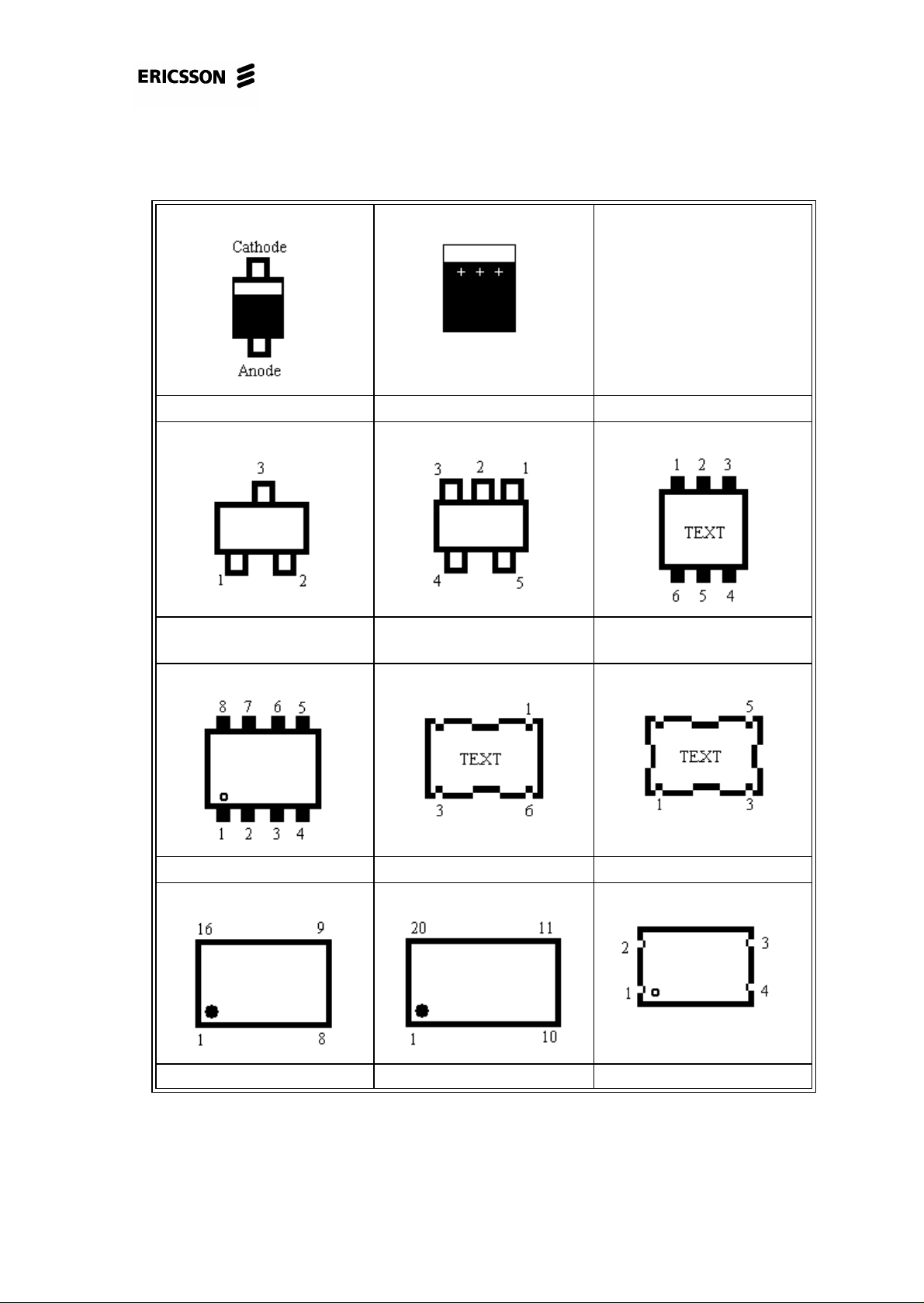
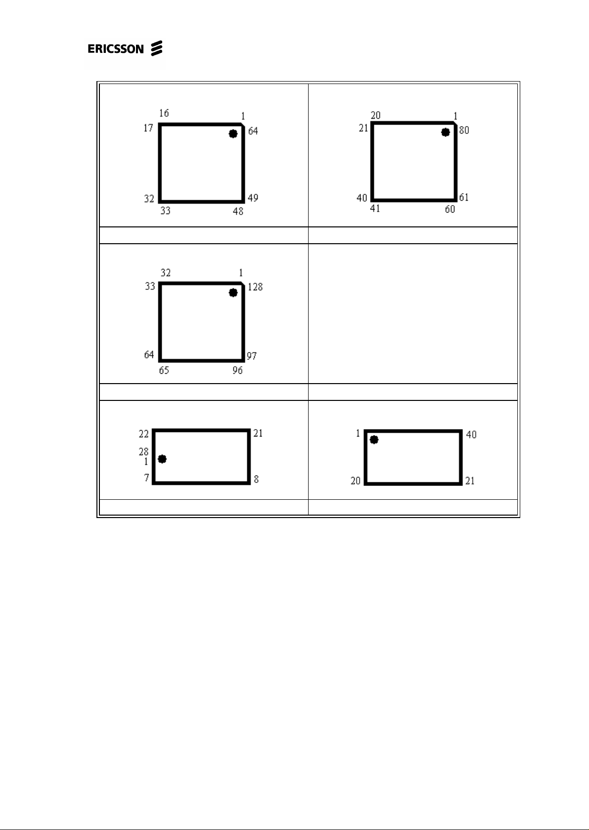
1.3 Pin placements
Single diode (PIN diode). Electrolytic capacitor.
Double diode or single trans-
stor.
Eight pin circuit. Tx VCO circuit (G300) LO VCO circuit (G350)
Sixteen pin circuit Twenty pin circuit Crystal
Five pin circuit (usually volt-
age regulator).
Double transistor.
4/00021-2/FEA 209 544/11.C 6 (68)
Page 7
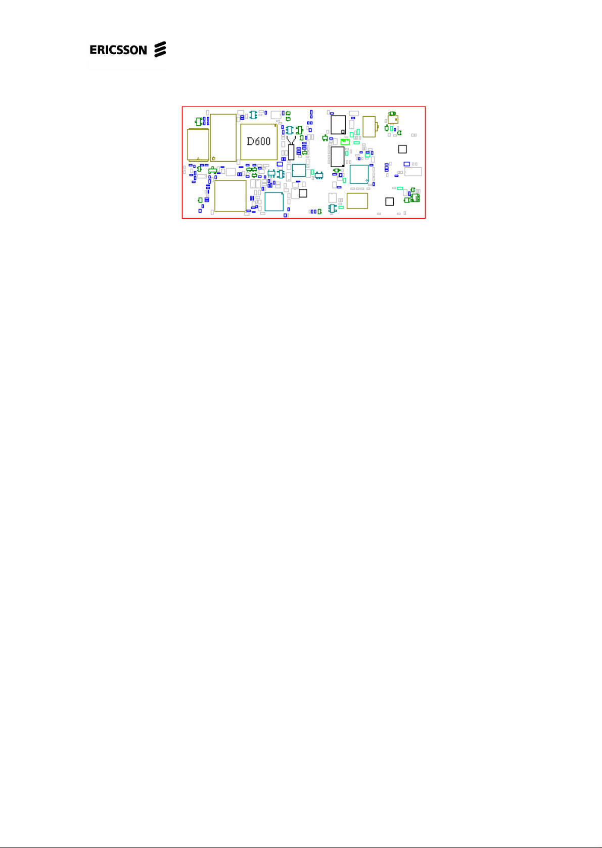
PF768, Standard Electrical Repairs
N800 D900
D600
D620 D610
4/00021-2/FEA 209 544/11.C 7 (68)
Page 8
PF768, Standard Electrical Repairs
2 No serv/not able to connect calls.
2.1 Finding out if the fault is Rx- or Tx-related.
Connect the phone (with signalling program) to a GSM test instrument and try to
get serv at –68.5dBm signal strength.
• If the phone doesn’t get serv, proceed to section 2.2.
• If the phone gets serv, proceed to section 2.3.
2.2 The phone doesn’t get serv.
Open the phone and check for liquid damages.
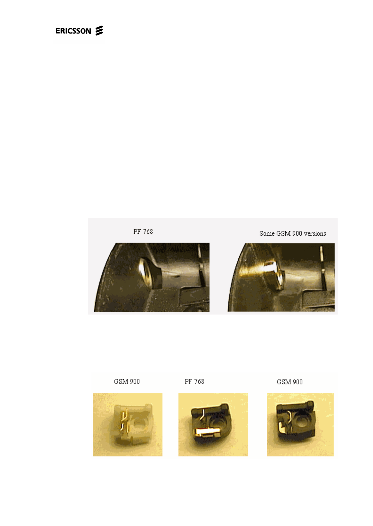
Make sure the back cover is intact and that it’sof the right model since there are two
models available. Fig. 2.1 shows which back cover model to use.
Fig. 2.1
Replace the antenna connector and try again. Note that there are several models of
the antenna connector and it’s important not to mount the wrong model. Fig. 2.2
shows which antenna connector model is to be used.
Fig. 2.2
4/00021-2/FEA 209 544/11.C 8 (68)
Page 9

PF768, Standard Electrical Repairs
• If the phone gets serv, proceed to section 2.3.
• If the phone doesn’t get serv there is probably a LO-part fault or the losses in the
signal path are too great. It’s also possible it could be a feed voltage fault.
If the fault remains, send the phone to the next level.
2.3 Connect a call towards the GSM test instru-
ment at power level 0 and –68.5dBm input
signal strength.
If you’re able to connect a call, proceed to section 2.4.
If you’re not able to connect a call, open the phone and check for liquid damages.
Make sure the back cover is intact and of the correct model since there are 2 models
(fig. 2.1).
Replace the antenna connector (if you haven’t replaced it already) and try again.
Note that there are several different models of the antenna connector too and it’s
important to mount the correct one.
• If you where able to connect a call, proceed to section 2.4.
The fault is probably Tx related or it’s a feed voltage fault if you still aren’t able to
connect calls.
If the fault remains, send the phone to the next level.
2.4 Read the Rx-level value from the instru-
ment while the call still is connected.
If the Rx-level value is at 42 2 steps, make sure the output power is 28-32dBm.
• The phone probably isn’t faulty if that’s correct.
Lower the signal from the instrument to –102.5dBm and make sure the Rx-level
value is 4-12 steps and that the Rx-quality value is 0-2 steps.
Try running the phone through the test again.
• If the phone passes the test but isn’t able to connect a call towards the “real” net,
make sure the phone hasn’t been locked out of the system due to theft. If it
hasn’t, replace D600 (class B, fig. 2.3).
4/00021-2/FEA 209 544/11.C 9 (68)
Page 10
PF768, Standard Electrical Repairs
Fig. 2.3
If the output power is too low or if the Rx-quality value or the RX-level vaule is too
high, send the phone to the next level.
If the Rx-level value is below 39 steps at –68.5dBm input signal strength or below 4
steps at –102.5dBm input signal strength, then the fault is Rx-related.
Open the phone and check for liquid damages.
Make sure the back cover is intact and that it’sof the right model since there are two
models available. Fig. 2.1 shows which back cover model to use.
Replace the antenna connector and try again. Note that there are several models of
the antenna connector and you must mount the correct model. Fig. 2.2 shows which
antenna connector model is to be used.
If the fault remains, send the phone to the next level.
4/00021-2/FEA 209 544/11.C 10 (68)
Page 11
PF768, Standard Electrical Repairs
3 Doesn’t start.
3.1 Find out if the phone starts by pressing the
On/Off key.
Insert a fully charged battery and press the On/Off key.
• If the phone doesn’t start, proceed to section 3.2.
• If the phone starts, turn off the phone and check the charging function by con-
necting a charger into the system connector.
* If the phone doesn’t start or doesn’t charge, send the phone to the next level.
* If the phone starts (lights the background illumination, asks for SIM or PIN,
seeks net…) and the charging function is ok then there’s probably nothing
wrong with the phone or the fault is intermittent.
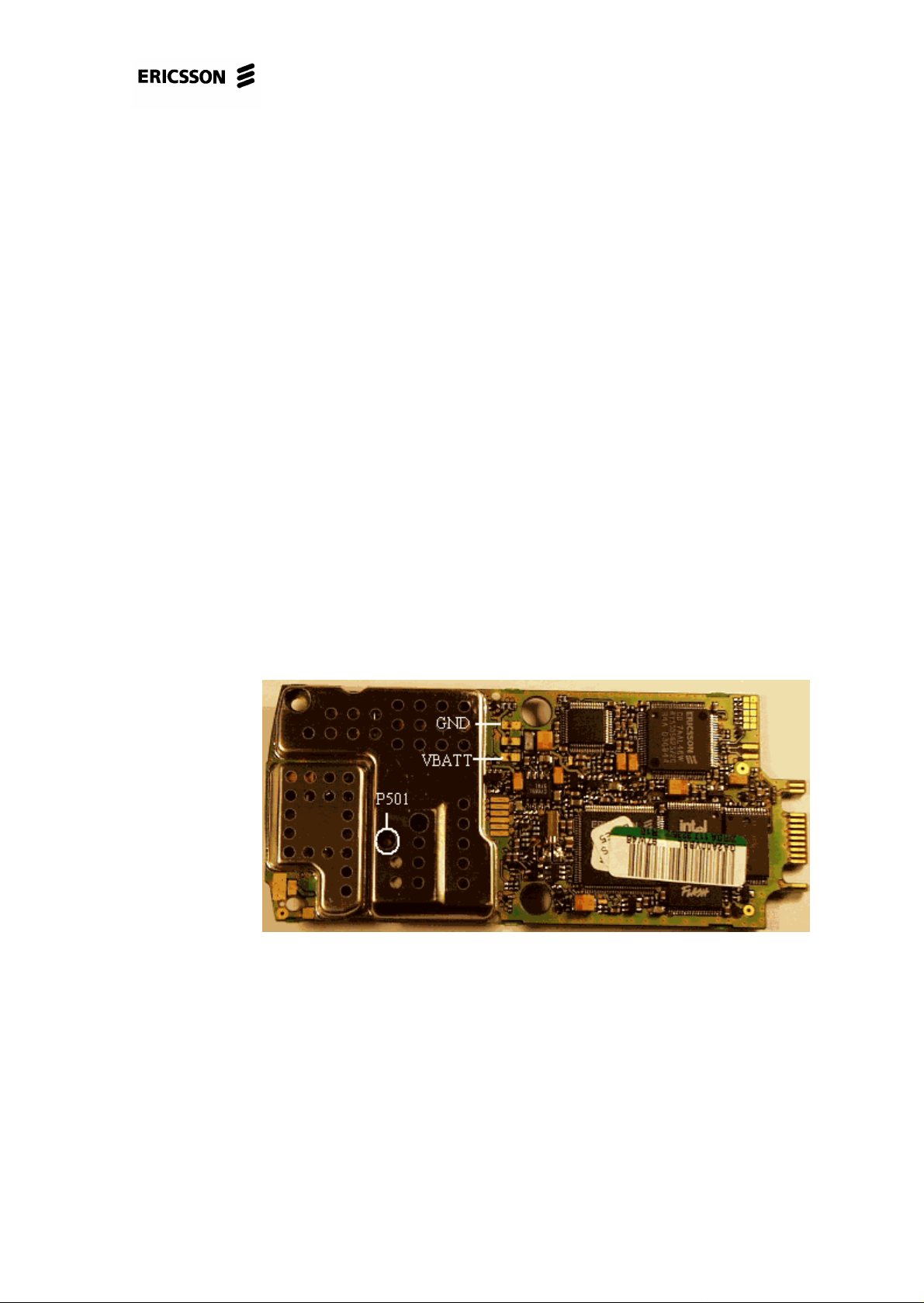
Open the phone and make a visual check of the circuit board.
Check for eventual liquid damages at the circuit board and dirt or oxide at the sys-
tem and battery connector pads.
Fig. 3.1 shows typical dirt at the battery connector pads.
Fig. 3.1
Make sure the dome switches isn’t damaged, especially at the On/Off key.
Make sure D600, D610 and D620 are soldered correctly (fig. 3.2).
4/00021-2/FEA 209 544/11.C 11 (68)
Page 12
PF768, Standard Electrical Repairs
Fig. 3.2
Send the phone through the normal flow as soon as you’ve fixed the fault.
3.2 Visual check.
Make an outer visual check:
• Make sure the battery connector is intact and that there aren’t any dirt or oxide at
the connector pins.
• Make sure there’s no dirt or oxide at the battery connector pads.
• Make sure the system connector isn’t damaged or dirty.
Continue at 3.3.
3.3 Current consumption with the On/Off key
pressed.
Insert a dummy battery into the phone.
• If the phone consumes current immediately, proceed to section 3.4.1.
Start the phone by pressing the On/Off key and check the current consumption.
• If the phone doesn’t consume any current when you keep the On/Off key pressed
it most probably is due to faulty dome switches.
Open the phone and remove the dome switches.
Make sure the board isn’t liquid damaged or dirty, especially around the On/Offkey.
Dirt is washed away by using alcohol and a brush.
Mount a new dome switches (note that the board must be dry before mounting the
dome switches).
4/00021-2/FEA 209 544/11.C 12 (68)
Page 13

PF768, Standard Electrical Repairs
Give the board power and start it up by pressing the On/Off key (in the fixture or in
the back cover with a dummy battery inserted, mount system connector to make the
board lie steady in the back cover).
* If the phone still doesn’t consume any current when the On/Off key is
pressed, proceed to section 3.4.2.
• If the phone consumes more than 200mA, remove the display and try again.
* If the consumption decreased it was the display that was faulty.
* If the consumption still is high, proceed to section 3.4.3.
• If the phone consumes 1-200mA, starts (asks for SIM, seeks net…) and runs as
long as you keep the On/Off key pressed but dies when you release the key, proceed to section 3.4.4.
• If the phone doesn’t start, try to program it in the flash programmer.
* If the phone doesn’t start in the flash programmer, proceed to section 3.4.5.
* If you can program the phone but it doesn’t start afterwards or if the phone
is troublesome in the flash programmer, proceed to section 3.4.6
* If the phone starts once it’s programmed in the flash programmer it proba-
bly isn’t a faulty phone. To eliminate intermittent faults, check the board for
liquid damages and check if the D600, D610 and D620 (fig. 3.2) chips are
correctly soldered.
3.4 Measuring a powered board.
3.4.1 Consumes power immediately when battery is
inserted.
Open the phone and check for liquid damages.
Make sure the battery and system connector pads aren’t liquid damaged, dirty or
oxidised.
Remove the dome switches. Clean the keypads using alcohol and a brush.
Put the board in the fixture without starting it up.
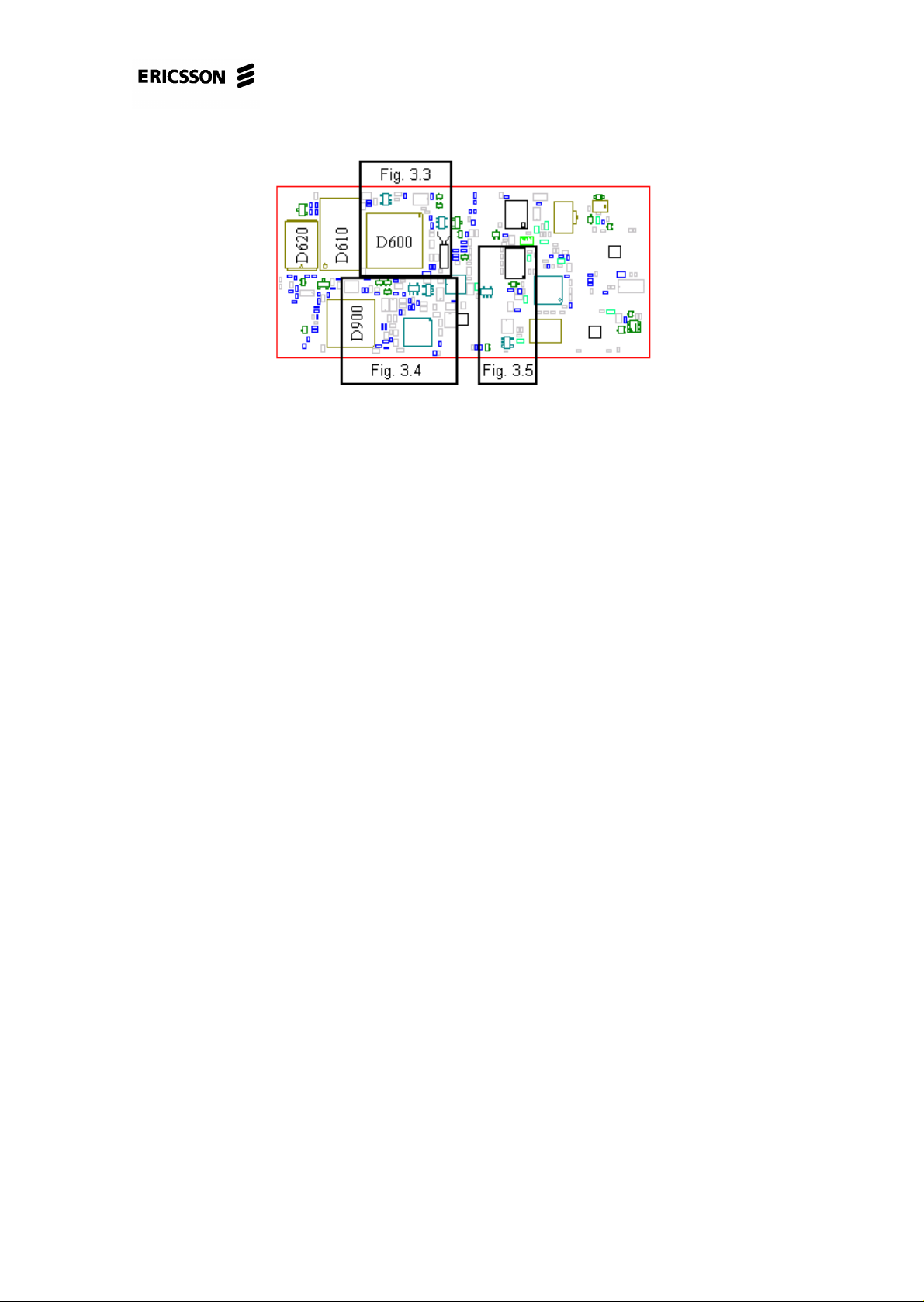
Measure the VDIG, VANA, VDSP, VRAD, VVCO and VRPAD feed voltages
(~0V).
Fig. 3.1 shows the measuring point for VRAD (P501) and fig. 3.3 show the measuring point for VDIG.
4/00021-2/FEA 209 544/11.C 13 (68)
Page 14
PF768, Standard Electrical Repairs
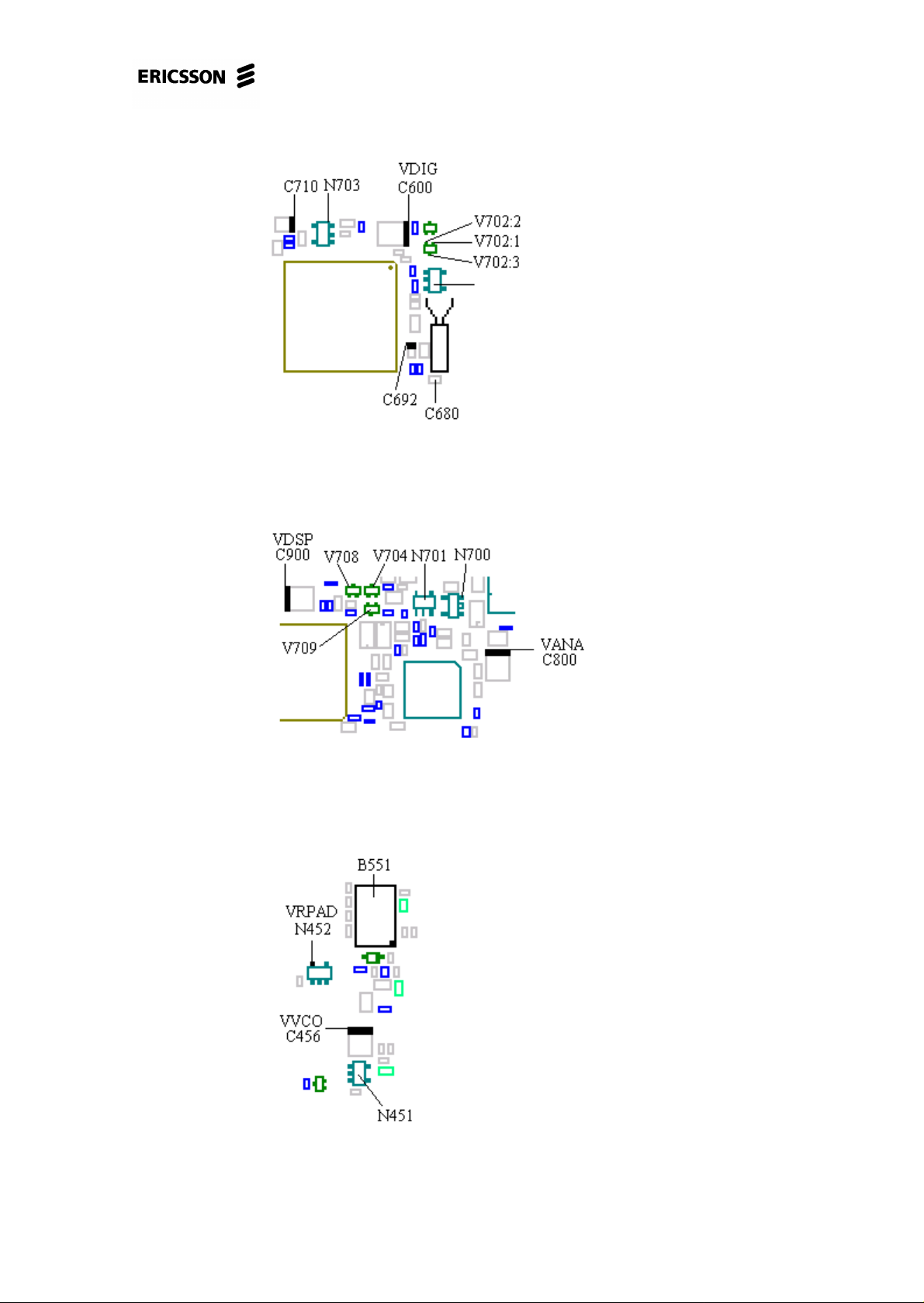
Fig. 3.3
Fig. 3.4 shows the measuring point for VANA and VDSP.
Fig. 3.4
Fig. 3.5 shows the measuring point for VRPAD and VVCO.
Fig. 3.5
4/00021-2/FEA 209 544/11.C 14 (68)
Page 15
PF768, Standard Electrical Repairs
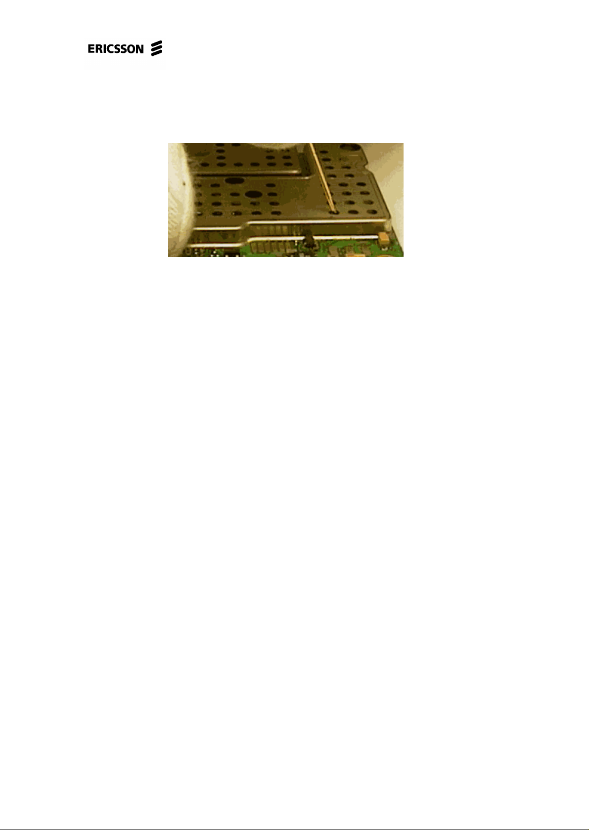
Since the measuring point for VVCO is under the big radio shielding (E202) you
have to measure the voltage carefully through one of the holes with a thin and preferably isolated probe as in fig. 3.6.
Fig. 3.6
• If there is voltage at any of the voltages but not all, replace the corresponding
regulator (VDIG – N702, VANA – N700, VDSP – N701, VRAD – N453, VVCO
– N451, VRPAD – N452, all of them class A). Note that the N453 and N451
regulators are under the radio shieldings and can therefore not be replaced
at this level.
• If there is voltage at all of the regulators, measure REGON at V702 pins 2 and 3
(fig. 3.3, ~0V).
* The REGON signal probably comes from one of the regulators or from
V704, V708 or V709 (fig. 3.4) if there’s no voltage at V702 pins 2 and 3.
Replace a component at a time and check after every component replaced.
* If there’s voltage at both pin 2 and pin 3 or V702 there’s probably a short
circuit at the pads for the On/Off key. It’s almost always crumbs from the
dome switches that causes this short circuit. Wash it away using alcohol and a
brush.
If the fault remains, send the phone to the next level.
3.4.2 Consumes no current when On/Off key is being
pressed.
Open the phone and check for liquid damages.
Make sure the battery and system connector pads aren’t dirty, liquid damaged or
oxidised.
Give the board power and start it up by pressing the On/Off key (in the fixture or in
the back cover with a dummy battery inserted, mount system connector to make the
board lie steady in the back cover).
Check the current consumption.
4/00021-2/FEA 209 544/11.C 15 (68)
Page 16
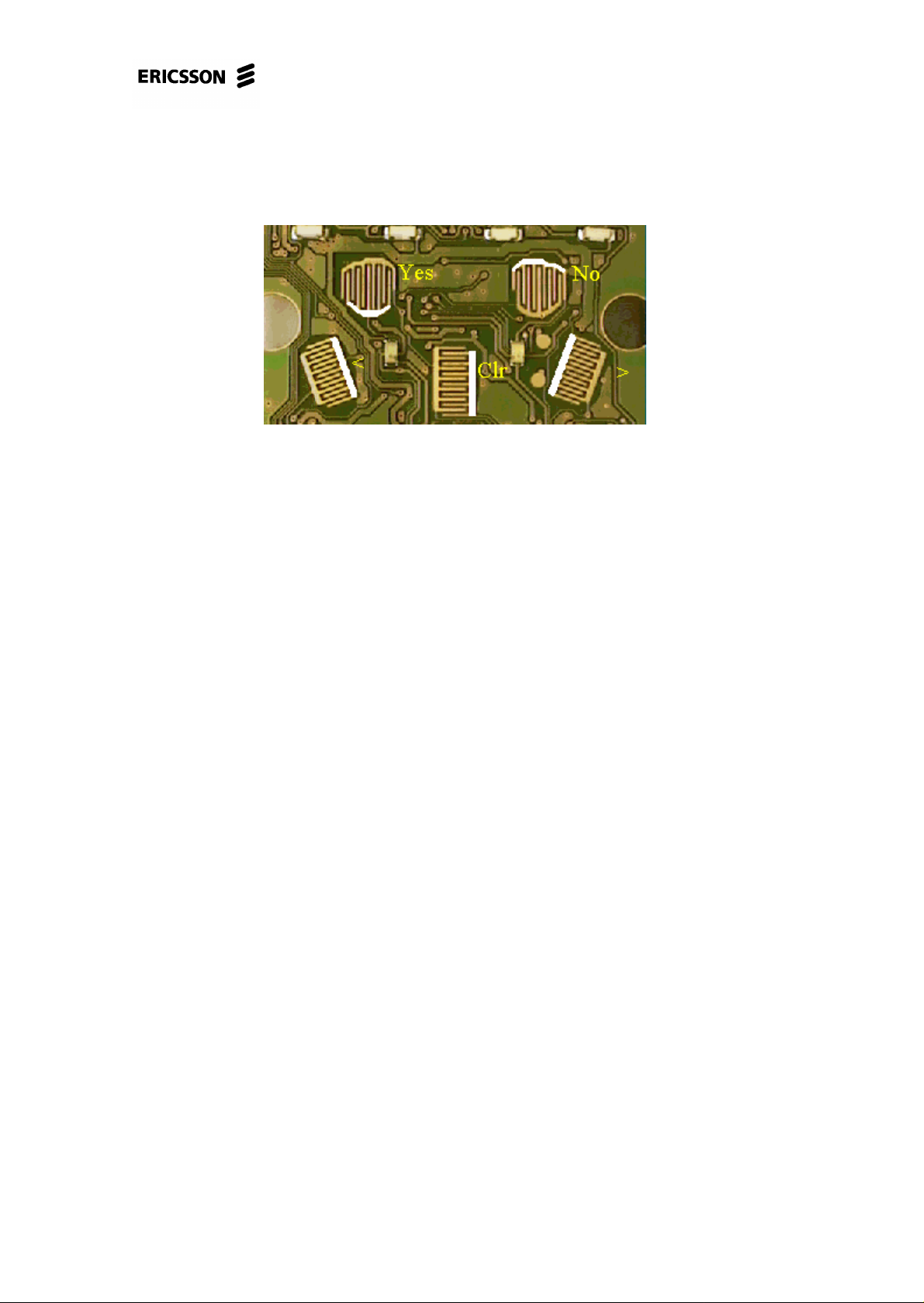
PF768, Standard Electrical Repairs
• If the phone still doesn’t consume any current, measure the resistances from the
unmarked side of the “No” keypad (fig. 3.7) to pin 2 of V702 (~0 ohms, fig. 3.3)
and from pin 3 of V702 to pin 3 if N702 (~0 ohms, fig. 3.3).
Fig. 3.7
* If one or both of the resistances are too high there’s a foil damage and the
phone is to be discarded.
* If the resistances are correct, replace V702 (class A).
If the fault remains, send the phone to the next level.
3.4.3 Consumes more than 200mA.
Open the phone and check for liquid damages.
Make sure the battery and system connector pads aren’t dirty, liquid damaged or
oxidised.
Place the board in the fixture. Keep it running by keeping DCIO high.
Check the VDIG, VANA and VDSP voltages (~3.2V, fig. 3.3 and 3.4).
• If any of the voltages are too low, measure the resistance from it to ground
(VDIG>500 ohms, VANA>25 kohms, VDSP>25kohms).
* If the resistance is correct, replace the corresponding regulator (VDIG –
N702, VANA – N700, VDSP – N701, all of class A).
* If the resistance is too low there’sa short circuit in one of the circuits fed by
the regulator. Send the phone to the next level.
• If any of the voltages are too high, replace the corresponding regulator.
Check the VRAD (fig. 3.1, P501 measuring point), VVCO (fig. 3.5) and VRPAD
(fig. 3.5) voltages (all of them ~3.8V).
Note that P501 is a calibration point. It is VRAD you measure but after 2 resistors.
The calibration point has the right voltage as long as the transmitter isn’t activated.
4/00021-2/FEA 209 544/11.C 16 (68)
Page 17

PF768, Standard Electrical Repairs
Also note that the measuring point for VVCO is under the big radio shielding
(E202) and therefore you have to measure the voltage carefully through one of the
holes with a thin and preferably isolated probe as in fig. 3.6.
• If the VRAD or VVCO voltage is incorrect, send the phone to the next level.
• If the VRPAD voltage is too low, measure the resistance from it to ground (>25
kohms).
* If the resistance is correct, replace N452 (class A)..
* If the resistance is too low there’sa short circuit in one of the circuits fed by
the regulator. Send the phone to the next level.
• If the VRPAD voltage is too high, replace N452.
Measure the resistance from VBATT to ground (>200 kohms, fig. 3.1).
• If the resistance is too low there’s a short circuit in one of the circuits fed by
VBATT. Send the phone to the next level.
If the fault remains, send the phone to the next level.
3.4.4 The phone runs as long as the On/Off key is
pressed.
Open the phone and check for liquid damages.
Make sure the battery and system connector pads aren’t dirty, liquid damaged or
oxidised.
Place the board in the fixture. Keep the board running by keeping the On/Off key
pressed.
Measure the voltage at C692 (~3.1V, fig. 3.3).
• If there is voltage, make sure pin 119 of D600 is correctly soldered.
* If the soldering is correct, replace D600 (class B, fig. 3.2).
• If there is no voltage at C692, measure the resistance of C692 (class A, >200
kohms).
* If the resistance is too low, replace C692 and check the voltage again.
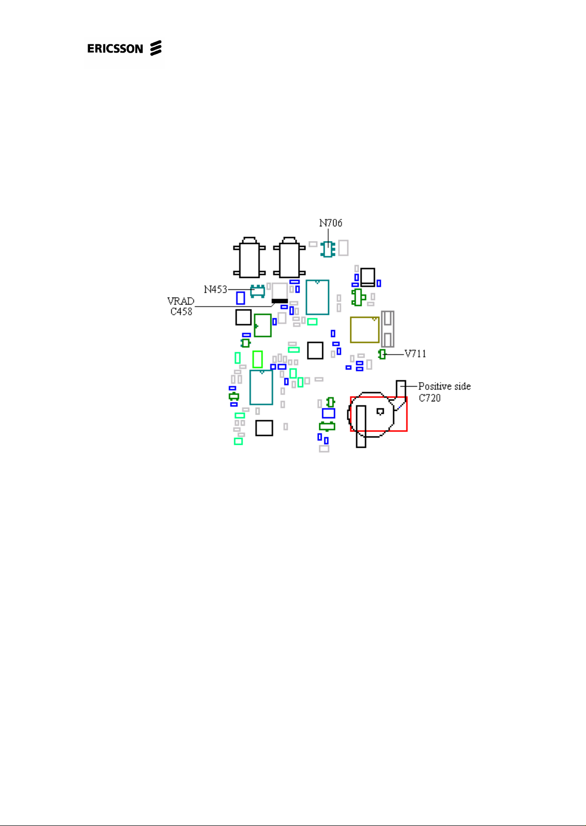
* If the resistance is correct, check the voltages at N706 (fig. 3.8). VBATT at
pin 2, ground at pin 1 and the output voltage (~3.5V) at pin 3.
* If VBATT or ground is missing there’s a foil damage and the phone is to
be discarded.
* If VBATT and ground are correct but not the output voltage, replace
N706.
4/00021-2/FEA 209 544/11.C 17 (68)
Page 18
PF768, Standard Electrical Repairs
* If all the voltages are correct, measure the VRTC voltage between the
positive side of C720 (class A, ~3.1V, fig. 3.8) and ground.
* If there’s no VRTC voltage, replace V711 (class A, fig. 3.8).
* If there’s VRTC voltage, measure the resistance from the positive
side of C720 (fig. 3.8) to the marked side of C692 (fig. 3.3, ~0 ohms).
* If the resistance is too high there’s a foil damage and the phone is
to be discarded.
Fig. 3.8
If the fault remains, send the phone to the next level.
3.4.5 Doesn’t start in the flash programmer.
Open the phone and check for liquid damages.
Make sure the battery and system connector pads aren’t dirty, liquid damaged or
oxidised.
Place the board in the fixture. Keep the board running by keeping DCIO high.
Check the VANA and VDIG voltages (~3.2V, fig. 3.4 and 3.3).
• If any of the voltages are too low, measure the resistance from it to ground
(VDIG>500 ohms, VANA>25 kohms).
* If the resistance is correct, replace the corresponding regulator(VDIG –
N702, VANA – N700, both of class A).
4/00021-2/FEA 209 544/11.C 18 (68)
Page 19

PF768, Standard Electrical Repairs
* If the resistance is too low there’sa short circuit in one of the circuits fed by
the regulator. Send the phone to the next level.
• If any of the voltages are too high, replace the corresponding regulator.
Check the power reset voltage at C710 (fig. 3.3, >3V).
• If it’s too low, replace C710 (class A) and measure again.
* If that doesn’t help, replace N703 (class A, fig. 3.3).
Check the VRAD (fig. 3.1, P501 measuring point), VVCO (fig. 3.5) and VRPAD
(fig. 3.5) voltages (all of them ~3.8V).
Note that P501 is a calibration point. It is VRAD you measure but after 2 resistors.
The calibration point has the right voltage as long as the transmitter isn’t activated.
Also note that the measuring point for VVCO is under the big radio shielding
(E202) and therefore you have to measure the voltage carefully through one of the
holes with a thin and preferably isolated probe as in fig. 3.6.
• If the VRAD or the VVCO voltage is incorrect, send the phone to the next level.
• If the VRPAD voltage is too low, measure the resistance from it to ground (>25
kohms).
* If the resistance is correct, replace N452 (class A).
* If the resistance is too low there’sa short circuit in one of the circuits fed by
the regulator. Send the phone to the next level.
• If the VRPAD voltage is too high, replace N452.
• If all the feed voltages are correct, check the amplitude of the clock frequency at
C680 (class A, >0.6V t-t, fig. 3.3). To check the amplitude you can use an oscilloscope, spectrum analyser, frequency counter, diode probe or similar. The D900
circuit usually gets warm when the system clock frequency is missing.
* If the amplitude is too low, send the phone to the next level.
Make sure there aren’t any faulty solderings at D600, D610 or D620 (fig. 3.2).
• If they look ok, replace D610 (class A). Do not replace any component if you
haven’t established the fact that the amplitude at C680 is correct.
* If that doesn’t help, replace D600 (class B) first and then D620 (class A) if
that doesn’t help. Try programming the phone in the flash programmer after
every circuit replaced.
If the fault remains, send the phone to the next level.
4/00021-2/FEA 209 544/11.C 19 (68)
Page 20

PF768, Standard Electrical Repairs
3.4.6 Able to program the phone but it doesn’t start
afterwards or it is troublesome in the flash programmer.
Open the phone and check for liquid damages.
Make sure the battery and system connector pads aren’t dirty, liquid damaged or
oxidised.
Place the board in the fixture. Keep the board running by keeping DCIO high.
Check the VANA and VDIG voltages (~3.2V, fig. 3.4 and 3.3).
• If any of the voltages are too low, measure the resistance from it to ground
(VDIG>500 ohms, VANA>25 kohms).
* If the resistance is correct, replace the corresponding regulator (VDIG –
N702, VANA – N700, both of class A).
* If the resistance is too low there’sa short circuit in one of the circuits fed by
the regulator. Send the phone to the next level.
• If any of the voltages are too high, replace the corresponding regulator.
Check the VRAD (fig. 3.1, P501 measuring point), VVCO (fig. 3.5) and VRPAD
(fig. 3.5) voltages (all of them ~3.8V).
Note that P501 is a calibration point. It is VRAD you measure but after 2 resistors.
The calibration point has the right voltage as long as the transmitter isn’t activated.
Also note that the measuring point for VVCO is under the big radio shielding
(E202) and therefore you have to measure the voltage carefully through one of the
holes with a thin and preferably isolated probe as in fig. 3.6.
• If the VRAD or the VVCO voltage is incorrect, send the phone to the next level.
• If the VRPAD voltage is too low, measure the resistance from it to ground (>25
kohms).
* If the resistance is correct, replace N452 (class A).
* If the resistance is too low there’sa short circuit in one of the circuits fed by
the regulator. Send the phone to the next level.
• f the VRPAD voltage is too high, replace N452.
Make sure there aren’t any faulty solderings at D600, D610 or D620 (fig. 3.2).
• If they look ok, replace D610 (class A).
* If that doesn’t help, replace D600 (class B) first and then D620 (class A) if
that doesn’t help. Try programming the phone in the flash programmer after
every circuit replaced.
If the fault remains, send the phone to the next level.
4/00021-2/FEA 209 544/11.C 20 (68)
Page 21

4 Audio.
PF768, Standard Electrical Repairs
4.1 Type of fault.
Make a call from the phone that is to be tested (later called the phone) to a phone
that is working correctly (later called the reference phone).
Check the function of the microphone and the earphone.
Connect a handsfree unit to the system connector of the phone.
Check the function of the phone’s external connections by listening to the external
speaker/earphone when talking in the reference phone and by listening to the earphone of the reference phone when talking in the external mic of the phone.
• If there is low or no sound in the earphone of the phone, proceed to section 4.2.
• If both the earphone and the handsfree speaker don’t work, send the phone to the
next level.
• If the sensitivity of the microphone is low (low or no sound in the reference
phone), proceed to section 4.3.
• If both the microphone in the phone and the microphone of the handsfree don’t
work, send the phone to the next level.
• If both the microphone and the earphone don’t work, proceed to section 4.4.
• If the microphone, the earphone and the handsfree don’t work, send the phone to
the next level.
• If the microphone of the handsfree doesn’t work, proceed to section 4.5.
• If the speaker of the handsfree doesn’t work, proceed to section 4.6.
• If both the microphone and the speaker of the handsfree don’t work, proceed to
section 4.7.
• If the phone sounds strange (the sound is distorted, scrambled, full of static or
“chopped”), proceed to section 4.8.
4.2 Earphone out of order.
Open the phone and check for liquid damages.
Most of the earphone faults are mechanical. Therefore you should start with replac-
ing the front (with the earphone) to one you know works and try again.
• If the fault remains, make sure the earphone connector (X810, fig. 4.1) isn’t
faulty or incorrectly soldered.
4/00021-2/FEA 209 544/11.C 21 (68)
Page 22

PF768, Standard Electrical Repairs
Fig. 4.1
Check the solderings of N800 (fig. 4.3).
Fig. 4.2
Fig. 4.3
If the fault remains, send the phone to the next level.
4/00021-2/FEA 209 544/11.C 22 (68)
Page 23

PF768, Standard Electrical Repairs
4.3 Microphone out of order.
Open the phone and check for liquid damages.
Wash the system and microphone connector pads if needed.
Make sure the sound channel gasket is properly mounted and free from dust.
Replace the system connector and microphone with a pair you know work. Test the
phone again.
• If the fault remains, measure the resistance of C850 and C851 (both >100
kohms, class A, fig. 4.3). Measure the resistance of R816 (~470 ohms, fig. 4.4,
class A), R817 and R819 (~1 kohms, class A, fig. 4.3). Check the solderings of
N800 (fig. 4.3).
Fig. 4.4
If the fault remains, send the phone to the next level.
4.4 Both the earphone and the microphone of
the phone out of order.
Open the phone and check for liquid damages.
Make especially sure there’s no dirt or oxide between the components below the
dome switches (fig. 4.5) and at the system connector pads.
Fig. 4.5
4/00021-2/FEA 209 544/11.C 23 (68)
Page 24

PF768, Standard Electrical Repairs
Wash the circuit board if needed using alcohol and a brush.
Assemble the phone and test it as in 4.1.
If the fault remains, open the phone. Give the board power and start it up by pressing the On/Off key without the system cable connected.
Measure the VDSP (~3.2V, fig. 4.3) feed voltage.
• If the VDSP voltage is too low, replace N701 (class A, fig. 4.3).
• If the VDSP voltage still is too low after replacing the N701 circuit there is prob-
ably a short circuit in one of the components fed by the VDSP voltage regulator.
If that’s the case, send the phone to the next level.
Measure the voltage at both sides of R601 and at D600 pin 70 (~5V, fig. 4.3 and 4.2,
you follow the PHFI signal).
Measure the voltage at both sides of R605 and at D600 pin 67 (~5V, fig. 4.5 and 4.2,
you follow the EXTAUDI signal).
• If the voltage at only one side of R601 or R605 is too low, replace the corre-
sponding resistor (fig. 4.3 and 4.5, both of class A).
• If the voltage is too low at both sides of R601 or R605, check the VSIMPAD
voltage at marked sides of R635 and R636 (~5V, fig. 4.4 and 4.5).
* If there’s no voltage there, check the resistance from the marked side of
R635 or R636 to N705 pin 3 (~0 ohms, fig. 4.5/4.4, 4.2).
* If the resistance is too high there’s a foil damage and the phone is to be
discarded.
* If the resistance is correct, proceed to section 6.3.
* If the VSIMPAD voltage is correct, measure the resistances of R635 and
R636 (~22 kohms, fig. 4.4 or 4.5).
* If any of the resistances are incorrect, replace the corresponding resistor.
Measure the resistance from X602 pad 5 to ground (>100 kohms, fig. 4.6). Make
sure there’s no dirt or oxide between the components below the dome switches (the
components in fig. 4.5).
4/00021-2/FEA 209 544/11.C 24 (68)
Page 25

PF768, Standard Electrical Repairs
Fig. 4.6
• If the resistance is too low, wash carefully and measure again.
* If the resistance still is too low,remove R601 (class A, fig. 4.3) and measure
again.
* If the resistance increased, replace D600 (class B, fig. 4.2).
* If the resistance didn’t increase when removing the R601 resistor or if it
didn’t help to replace D600, send the phone to the next level.
Measure the resistance from X602 pad 3 to ground (>100 kohms). Make sure there’s
no dirt or oxide between the components at the marked area (fig. 4.8).
• If the resistance is too low, wash carefully and measure again.
* If the resistance still is too low,remove R605 (class A, fig. 4.5) and measure
again.
* If the resistance increased, replace D600 (class B, fig. 4.2).
* If the resistance didn’t increase or if it didn’t help to replace D600, send
the phone to the next level.
If all of the above measured resistances are correct but anyone of the voltages at
R601 or R605 are too low anyway, it usually is because of a short circuit caused by
dirt between the components in fig. 4.5.
If the voltages at R601 and R605 are correct, connect a handsfree to the system connector.
Measure the voltage at both sides of R601 (~0V, fig. 4.3) and at D600 pin 70 (~0V,
fig. 4.2).
• If the voltage isn’t correct, check the soldering at D600 pin 70 (fig. 4.2).
* If the soldering is correct, measure the resistance of R601 (~1 kohms, class
A).
4/00021-2/FEA 209 544/11.C 25 (68)
Page 26

PF768, Standard Electrical Repairs
* If the resistance is correct, replace D600 (class B).
• If the voltage is correct, check the solderings of N800 and D600 (fig. 4.3 and
4.2).
If the fault remains, send the phone to the next level.
4.5 Handsfree microphone out of order.
The fault occurs when there’s an interrupt in the audiopath between the handsfree
microphone (connected through the system connector) and the N800. The audio
path is shown in fig. 4.7.
Fig. 4.7
Open the phone and check for liquid damages, especially around the system connector pads (X602) 1, 2 and 4 (fig. 4.6).
Measure the resistance of C850 and C851 (both >100 kohms, fig. 4.3, class A).
Make sure all the components in fig. 4.7 (R830, R825, R802, R805, C835, C810
and C812) are mounted on the circuit board (fig. 4.3).
Check the solderings of N800 (fig. 4.3).
Give the board power and start it up by pressing the On/Off key without the system
cable connected.
Measure the voltage at the marked side of R825 (~3.1V, fig. 4.3).
• If there isn’t any voltage or if it is incorrect, check the VANA voltage at the
marked side of R830 (fig. 4.4).
* If the VANA voltage is incorrect, proceed to chapter 3 (“Doesn´t start”fault).
* If VANA is correct, check the resistances of R830 (~470 ohms), R825 (3.3
kohms) and C835 (>1 kohms, all of class A and in fig. 4.3).
4/00021-2/FEA 209 544/11.C 26 (68)
Page 27

PF768, Standard Electrical Repairs
• If there’s correct voltage at R825, check the resistance of C810 (>10 kohms),
C812 (>100 kohms), R802 (~3.9 kohms) and R805 (~15 kohms, all of class A
and in fig. 4.3).
If the fault remains, send the phone to the next level.
4.6 Handsfree speaker out of order.
The fault occurs when there’s an interrupt in the audio path from the N800 to the
handsfree speaker (connected through the system connector). The audio path is
shown in fig. 4.8.
Fig. 4.8
Open the phone and check for liquid damages, especially around the system connector pads (X602, fig. 4.6) 1, 2 and 4.
Measure the resistance of C850 and C851 (both >100 kohms, both of class A and in
fig. 4.3).
Make sure all the components in fig. 4.8 (R803, R804 and C813) are mounted at the
circuit board (fig. 4.4).
Check the solderings of N800 (fig. 4.3).
Measure the resistances of R803 (~100 ohms), R804 (~100 kohms) and C813 (>100
kohms, all of class A and in fig. 4.4).
Measure the resistance from the marked side of R803 to pad 1 of X602 (~0 ohms,
fig. 4.4 and 4.6).
• If the resistance is too high there’s a foil damage and the phone is to be dis-
carded.
If the fault remains, send the phone to the next level.
4/00021-2/FEA 209 544/11.C 27 (68)
Page 28

PF768, Standard Electrical Repairs
4.7 Both the microphone and the speaker of
the handsfree out of order.
Open the phone and check for liquid damages, especially at the components in fig.
4.5.
Wash the above mentioned components using alcohol and a brush.
Measure the resistance from X602 pad 3 to the unmarked side of R635 (~0 ohms,
fig. 4.6 and 4.5).
Measure the resistance from X602 pad 2 to the unmarked side of R636 (~0 ohms,
fig. 4.6 and 4.4).
• If any of the resistances are incorrect there’s a foil damage and the phone is to be
discarded.
Measure the resistances of R601 and R605 (~1 kohms, class A, fig. 4.3 and 4.5).
If all the resistances are correct, check the solderings of N800 and D600 (fig. 4.3
and 4.2).
If the fault remains, send the phone to the next level.
4.8 The phone sounds strange (the sound is
distorted, scrambled, full of static or
“chopped”).
Open the phone and check for liquid damages.
Give the board power and start it up by pressing the On/Off key.
Measure the VDSP feed voltage (~3.2V, fig. 4.3).
• If the VDSP voltage is too low, replace N701 (class A, fig. 4.3).
* If the VDSP voltage still is too low after replacing the N701 circuit there is
probably a short circuit in one of the components fed by the VDSP voltage
regulator. If that’s the case, send the phone to the next level.
• If the voltage is correct, check the solderings of N800 and D600 (fig. 4.3 and
4.2).
If the fault remains, send the phone to the next level.
4/00021-2/FEA 209 544/11.C 28 (68)
Page 29

PF768, Standard Electrical Repairs
5 Display.
5.1 Kind of fault.
Insert a charged battery into the phone and start it up by pressing the On/Off key.
• If it doesn’t start, proceed to chapter 3 (“Doesn´t start”-fault).
• If the display is missing one or more segments, proceed to section 5.2.
• If there’s nothing being displayed in the display or if the contrast is low, proceed
• If the display is black (all the segments are “lit” and you can sometimes make
5.2 Segments are missing.
Open the phone and check for liquid damages. Replace the display.
to section 5.3
out what it’s displaying), proceed to section 5.4.
5.3 There’s nothing showing in the display or
the contrast is low.
Insert a dummy battery into the phone, start it up and check the current consumption. You could also disassemble the phone, place the board in the fixture, give the
board power, start it up by pressing the On/Off key or by pulling DCIO high and
check the current consumption.
• If the phone consumes more than 200mA, make sure the display isn’t mechani-
cally damaged.
* If the display is ok, replace the elastomer and try again.
* If that doesn’t help, replace the display and try again.
* If the current consumption still is too high, proceed to chapter 3
(“Doesn´t start”-fault).
• If the phone consumes less than 200mA, open the phone and check for liquid
damages.
Give the board power and start it up without the display mounted.
The component side of the circuit board is shown in fig. 5.1.
4/00021-2/FEA 209 544/11.C 29 (68)
Page 30

PF768, Standard Electrical Repairs
Fig. 5.1
Measure the voltages at the V608 diode (class A). Compare the results to the values
at fig. 5.2.
Fig. 5.2
All values are approximately 0.2V.
• If any of the voltages differ from the ones in fig. 5.2, measure the resistances of
C633 (class A, >100 kohms, fig. 5.2) and C824 (class A, >25 kohms, fig. 5.2).
* If any of the resistances are too low, replace the corresponding capacitor.
4/00021-2/FEA 209 544/11.C 30 (68)
Page 31

PF768, Standard Electrical Repairs
* If the resistances and the VRPAD voltage are correct, replace the V608
diode.
* If the voltages at the diode (except VRPAD) still are incorrect after
replacing it, make sure pin 96 of D600 is correctly soldered.
* If the soldering is correct, replace C632 (class A, fig. 5.2) and meas-
ure the voltages again.
* If that doesn’t help, replace D600 (class B).
• If the VRPAD voltage is incorrect, proceed to chapter 3 (“Doesn´t start”-fault).
Fig. 5.3
Fig. 5.4
• If the voltages at V608 are correct but there still isn’t anything showing in the
display, measure the voltages at the display pads (H622, fig. 5.4).
Pad 1 – (I
Pad 2 – (I
2
C-CLOCK): ~3.2V
2
C-DATA): ~3.2V
Pad 3 – (VDIG): ~3.2V
Pad 4 – (VDIG): ~3.2V
Pad 5 – (GND)
Pad 6 – (VLCD): ~4.6V
Make sure there’s VLCD voltage (~4.6V) at pad 5.
4/00021-2/FEA 209 544/11.C 31 (68)
Page 32

PF768, Standard Electrical Repairs
• If there isn’t, check the resistances from H622 pad 6 to V608 (the VLCD marked
pin in fig. 5.2, ~0 ohms) and from pad 5 of H622 to ground (~0 ohms).
* If any of the resistances are too high there’s a foil damage and the phone is
to be discarded.
2
• If the I
at C600 (~3.2V, fig. 5.2)
C-DATA or the I2C-CLOCK voltage is missing, check the VDIG voltage
* If the VDIG voltage is incorrect, proceed to chapter 3 (“Doesn´tstart”fault).
* If the VDIG voltage is correct, measure the resistances of R619 (~2.2
kohms, fig. 5.2), R620 (~2.2 kohms, fig. 5.2), R615 (~10 kohms, fig. 5.5) and
R616 (~10 kohms, fig. 5.5, all of class A). Check the solderings of D600 pins
3 and 4 (fig. 5.1).
* If all the resistances and the solderings are correct, replace D600 (class
B).
5.4 The display is black (all the segments are
“lit” and you can sometimes make out
what it’s displaying).
Open the phone and check for liquid damages.
Give the board power and start it up by pressing the On/Off key. If the phone shuts
itself down after a few minutes, keep it running by keeping DCIO high.
Check the VDIG and VANA voltages (~3.2V, fig. 5.2).
• If any of the voltages are too low, measure the resistance from it to ground
(VDIG>500 ohms, VANA>25 kohms).
* If the resistance is correct, replace the corresponding circuit (VDIG – N702,
VANA – N700, both of class A).
* If the resistance is too low there’sa short circuit in one of the circuits fed by
the regulator. Send the phone to the next level.
• If any of the voltages are too high, replace the corresponding regulator.
If the fault remains, proceed to section 5.3 (nothing shows in the display or the display has low contrast).
4/00021-2/FEA 209 544/11.C 32 (68)
Page 33

PF768, Standard Electrical Repairs
6 SIM (“Insert card”).
6.1 What is SIM fault?
Insert a charged battery and a functional SIM card into the phone. Start it up by
pressing the On/Off key.
• If the phone displays “Wrong card” or “Insert correct card” in the display it
means that the phone is SIM-locked and it can’t be repaired at this level.
• If the phone displays “Phone lock” it means that the customer has locked the
phone with a personal code. The phone is unlocked in the reset part of the test
flow.
• If the phone displays “PIN:” or “Enter PIN” it means that the SIM card is
locked with a personal code.
• Only if the phone displays “Insert card” there’s a SIM fault.
6.2 Measuring VSIMPAD.
Measure the voltage between pin 8 and 10 of the system connector (~4.9V, fig. 6.1).
• If the voltage is too low or missing, proceed to section 6.3.
• If the voltage is correct, proceed to section 6.4.
Fig. 6.1
6.3 VSIMPAD voltage too low or missing.
Open the phone and check for liquid damages, especially around the system connector pads.
Measure the resistance of R724 (class A, ~47 ohms, fig. 6.2).
4/00021-2/FEA 209 544/11.C 33 (68)
Page 34

PF768, Standard Electrical Repairs
Fig. 6.2
Give the board power and start it up. Measure the input voltage at N705 pin 2
(~3.1V, fig. 6.4).
Fig. 6.3 shows the component side of the board.
Fig. 6.3
4/00021-2/FEA 209 544/11.C 34 (68)
Page 35

PF768, Standard Electrical Repairs
Fig. 6.4
• If the input voltage is too low or missing, check the VDIG (~3.2V) feed voltage
at C600 (fig. 6.4).
* If the VDIG voltage is too low, measure the resistance from it to ground.
* If the resistance is more than 500 ohms, replace N702 (class A, fig. 6.4).
* If it’s less, send the phone to the next level.
* If the VDIG voltage is correct, measure the resistance of R706 (class A,
~4.7 ohms, fig. 6.4).
* If the resistance is correct, check the resistance from the marked side of
R706 to the marked side of C600 (~0 ohms) and from the unmarked side
of R706 to pin 2 of N705 (~0 ohms).
* If any of the resistances are too high there’s a foil damage and the
phone is to be discarded.
• If the input voltage is correct, measure the output voltage (VSIMPAD, ~5V) at
N705 pin 3 (class A, fig. 6.4).
* If it’s incorrect, replace N705.
* If the output voltage is correct there can be a foil damage somewhere
between N705 pin 3 and R724 or between N705 pin 3 and V700 pin 2 (fig.
6.2 and 6.4). If there’s a foil damaged the phone is to be discarded.
6.4 VSIMPAD voltage is correct.
Open the phone and check for liquid damages.
Clean the SIM pads using alcohol and a brush.
4/00021-2/FEA 209 544/11.C 35 (68)
Page 36

PF768, Standard Electrical Repairs
Assemble the phone with a new SIM card holder and try again.
If the fault remains, disassemble the phone again.
Measure the resistance of R704 (class A, ~100 kohms, fig. 6.4).
Make sure pins 64 and 72-75 (fig. 6.3) are correctly soldered.
Measure the resistances of R600 (~33 ohms), R627 (~0 ohms) and R628 (~100
ohms, allof class A and in fig. 6.4).
Check the resistances from the marked side of R600 to X600 pad 2, from the
marked side of R627 to X600 pad 3 and from the marked side of R628 to X600 pad
7 (all ~0 ohms and in fig. 6.3/6.4).
• If any of these resistances are too high there’s a foil damage and the phone is to
be discarded.
• If the resistances are correct, replace D600 (class B, fig. 6.3).
If the fault remains, send the phone to the next level.
4/00021-2/FEA 209 544/11.C 36 (68)
Page 37

PF768, Standard Electrical Repairs
7 Keyboard
7.1 Kind of keyboard fault.
Insert a SIM card and a fully charged battery into the phone. Start the phone by
pressing the On/Off key.
• If it doesn’t start at all, proceed to chapter 3 (“Doesn´tstart”-fault).
Press all the keys (including the volume keys at the side) and verify which are func-
tional. Verification is most easily done like this:
1. Go to “key sound” in the menu. Choose “click”.
2. Press the 1, 2, 3…*, 0, # keys. A clicking sound should be heard at every key
pressed and the corresponding symbol should appear in the display.
3. Press the “Yes”, “No”, “clr”, “<” and “>” keys. When pressing “Yes” the phone
should attempt to place a call and when pressing “No” it should terminate it. The
“clr” key erases the symbols in the display one by one and the “<” and “>” keys
make you skim through the menu.
4. Press the volume keys on the side of the phone. A clicking sound should be
heard for every press of the keys.
• If only the volume keys aren’t functional, proceed to section 7.2.
• If one or more keys of the keyboard aren’t functional, proceed to section 7.3.
• If one or both of the volume keys and one or more keys of the keyboard aren’t
functional, proceed to section 7.2 and then to section 7.3.
7.2 Volume keys aren’t functional.
Open the phone and check for liquid damages, especially around the S820 and S821
switches (fig. 7.1).
Fig. 7.1
4/00021-2/FEA 209 544/11.C 37 (68)
Page 38

PF768, Standard Electrical Repairs
Make sure the S820 and S821 (both of class A) switches are intact and correctly soldered.
Measure the resistance of the switch that isn’t functional. You measure between pin
1/3 and 2/4 (fig. 7.2). The resistance should be >100 kohms when not pressed and
~0 ohms when pressed.
Fig. 7.2
• If the resistance is high all the time, replace the corresponding switch.
• If the resistance is low all the time, replace the corresponding switch first.
* If that doesn’t help, check the solderings at D600 pins 1, 123, 124 and 128.
* If the solderings are correct, replace D600 (class B, fig. 7.3).
Fig. 7.3
• If the switches work as they should, replace the volume keys and try again.
* If that doesn’t help, check the solderings at D600 pins 1, 123, 124 and 128.
* If the solderings are correct, replace D600 (class B, fig. 7.3).
7.3 One or more keys of the keyboard aren’t
functional.
Open the phone and check for liquid damages.
Remove the dome switches and check for liquid or mechanical damages, especially
around the keys that aren’t functional.
Clean the keypads thoroughly. Mount a new dome switches and make sure the key-
board isn’t damaged. Assemble the phone and check the function of the keys as in
7.1.
4/00021-2/FEA 209 544/11.C 38 (68)
Page 39

PF768, Standard Electrical Repairs
If that doesn’t help, open the phone. Give the board power and start it up (by pressing the On/Off key or setting DCIO high).
Schematic of the keyboard functions is shown in fig. 7.4.
Fig. 7.4
Measure the VDIG voltage (fig. 7.5, ~3.2V).
• If it’s incorrect, proceed to chapter 3 (“Doesn´t start”-fault).
• If the VDIG voltage is correct, check if there’s voltage (~3.2V) at the marked
sides of R630-R634 (fig. 7.5).
Fig. 7.5
* If the voltage is missing at one or more of the resistors, measure the resistance from the marked side of C600 to the marked side of the resistor in question (~0 ohms).
* If the resistance is too high there’s a foil damage and the phone is to be
discarded.
4/00021-2/FEA 209 544/11.C 39 (68)
Page 40

PF768, Standard Electrical Repairs
Measure the voltage at the unmarked side of the R630-R634 resistors (~3.2V).
• If the voltage is too low at one or more of the resistor, measure the resistance of
the corresponding resistor (all are of class A and ~100 kohms).
* If all the resistances are correct, check the solderings at D600 1, 120 and
122-128.
* If the solderings are correct, replace D600 (class B, fig. 7.3).
• If the voltages at both sides of all the resistors are correct, but the keyboard isn’t
functional, check the solderings at D600 pin 1, 120 and 122-128.
* If the solderings are correct, replace D600 (class B, fig. 7.3).
* If it doesn’t help replacing D600 remove the dome switches again.
Check if there’s VDIG (~3.2V) voltage at the marked sides of all the keypads in the row that isn’t functional (fig. 7.6). Note that there’s VBATT
(~4.8V) voltage at the marked side of the “No” keypad.
* If VBATT voltage is missing at the “No” keypad there’s a foil damage and the phone is to be discarded.
Fig. 7.6
* If the VDIG voltage is missing at a part of a row (as described in fig.
7.4) there’s a foil damage and the phone is to be discarded. This can
easily be verified by measuring the resistance from the marked side of
a functional keypad to the marked side of a non-functional keypad (~0
4/00021-2/FEA 209 544/11.C 40 (68)
Page 41

PF768, Standard Electrical Repairs
ohms). The foil damage is most usually caused by liquid damages. If
there, for instance, is voltage at the 4 and 5 keypads but not at the 6 and
“volume up” keypads there’s a foil damage somewhere between keypads 5 and 6 and the phone is to be discarded.
If a column or part of it isn’t functional, check the solderings at D600 pins 1 and
120-128.
• If all the solderings are correct, replace D600 (class B).
4/00021-2/FEA 209 544/11.C 41 (68)
Page 42

PF768, Standard Electrical Repairs
8 Illumination and buzzer.
8.1 Type of fault.
Insert a dummy battery and a SIM card into the phone, press the On/Off key and
wait for the phone to get serv (towards the net or a GSM test instrument).
• If the phone doesn’t beep at start, go to “menu/ring level” and try to increase the
ring level to full (not from full to step since that won’t generate any sound). If the
sound is faint or if you can’t hear it at all, proceed to section 8.2
• If one or more of the LEDs at the display illumination isn’t lit at start, proceed to
section 8.3.
• If one or more of the LEDs at the keyboard illumination isn’t lit at start, proceed
to section 8.3.
• If the top indicator doesn’t blink green when the phone has got serv, proceed to
section 8.4.
• If the top indicator blinks green when the phone has got serv, lower the battery
voltage to 4.2V. The top indicator should then start to blink red, the battery indicator should show an empty battery and the phone should warn with a beep.
* If the battery indicator doesn’t show an empty battery, the top indicator
doesn’t blink red and the phone doesn’t warn with a beep the phone needs a
voltage calibration.
* If the top indicator doesn’t blink red but the other things work, proceed to
section 8.6.
* If both the top indicators colours are faintly glowing and the buzzer sounds
faintly, proceed to section 8.7.
8.2 Buzzer faint or dead.
Open the phone and check for liquid damages.
The front side of the circuit board is shown in fig. 8.1.
Fig. 8.1
4/00021-2/FEA 209 544/11.C 42 (68)
Page 43
PF768, Standard Electrical Repairs
Make sure the buzzer (H600, class A, fig. 8.2) is correctly soldered.
• If the solderings are correct, replace the buzzer.
Assemble the phone and try the buzzer as in 8.1 again.
• If the fault is repaired, send the phone through the normal flow.
• If the fault remains, open the phone. Give the board power and start it up.
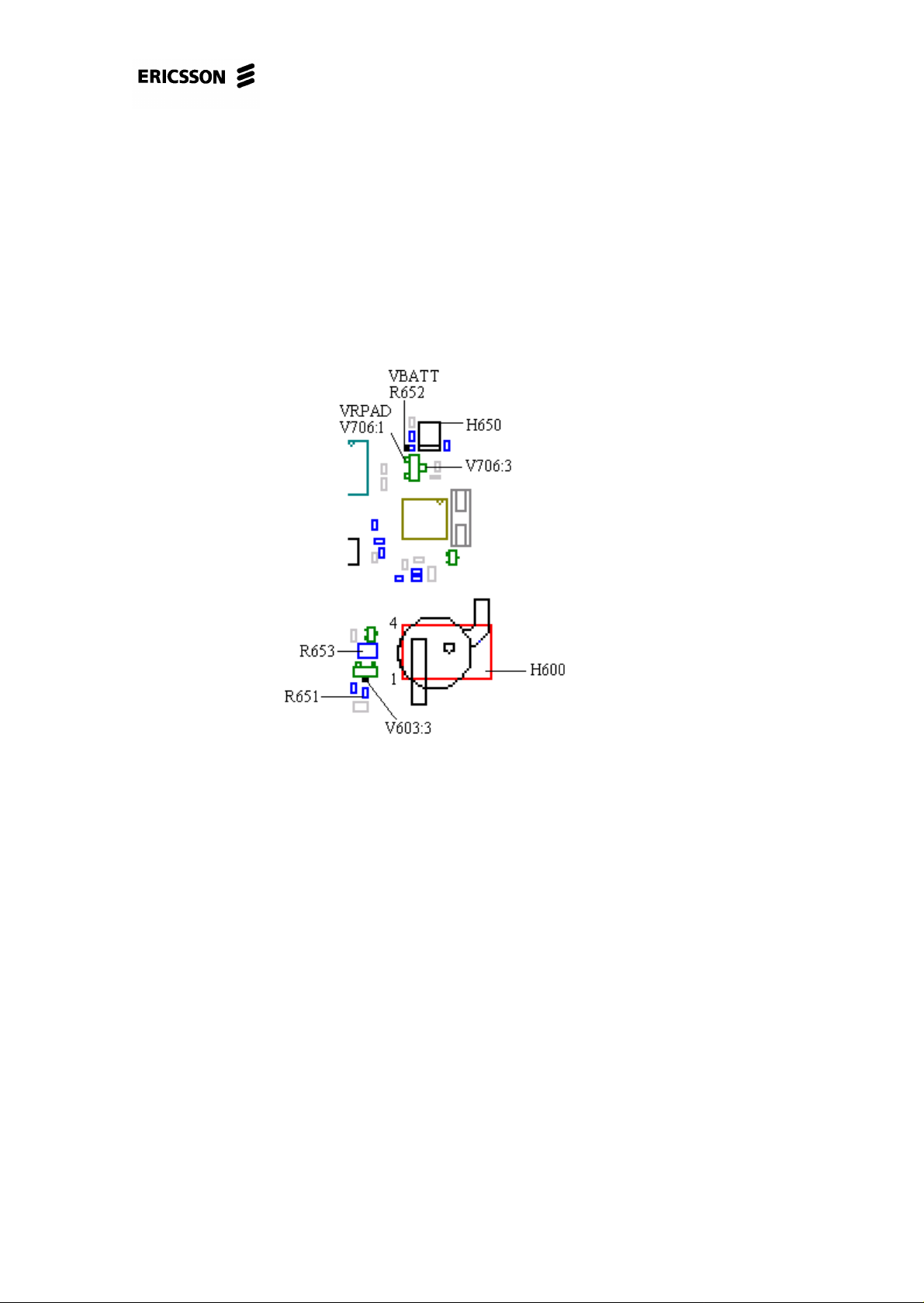
Measure the voltage at H600 pad 4 (~3.4V, fig. 8.2).
Fig. 8.2
• If the voltage at H600 pad 4 is missing, measure the VRPAD voltage (~3.8V) at
V706 pin 1 (class A, fig. 8.2).
* If the voltage at V706 pin 1 is missing, check if there’s VRPAD voltage at
N452 pin 5 (fig. 8.3).
4/00021-2/FEA 209 544/11.C 43 (68)
Page 44

PF768, Standard Electrical Repairs
Fig. 8.3
* If the VRPAD voltage is faulty or missing, proceed to chapter 3
(“Doesn´t start”-fault).
* If it’s correct, check the resistance from pin 2 of N452 to pin 1 of V706
(~0 ohms).
* If the resistance is too high it’s probably the L450 (~0 ohms, class A,
fig. 8.3) that’s faulty.
* If L450 isn’t faulty or incorrectly soldered there’s a foil damage
and the phone is to be discarded.
* If the VRPAD voltage at V706 is correct, measure the resistance from
VBATT to V706 pin 3 (~4.7 ohms, fig. 8.3 and 8.2).
* If the resistance is too high it’s probably R652 (~4.7 ohms, class A, fig.
8.2) that’s faulty.
* If the resistor isn’t faulty or incorrectly soldered there’sa foil damage
and the phone is to be discarded.
* If the resistance from VBATT to V706 is correct, replace V706 (class
A).
• If the voltage at pad 4 of H600 is correct, measure the resistance from H600 pad
1 to V606 pin 3 (~0 ohms, fig. 8.2).
* If the resistance is too high it’s probably R653 (~0 ohms, class A, fig. 8.2)
that’s faulty.
* If R653 isn’t faulty or incorrectly soldered there’s a foil damage and the
phone is to be discarded.
* If the resistance is correct, make sure pin 91 of D600 (fig. 8.3) is correctly
soldered.
* If it is correctly soldered, replace R651 (class A, fig. 8.3) and V606
(class A, fig. 8.2).
* If that doesn’t help, replace D600 (class B, fig. 8.3).
4/00021-2/FEA 209 544/11.C 44 (68)
Page 45

PF768, Standard Electrical Repairs
If the fault remains, send the phone to the next level.
8.3 The background illumination for the display
is missing or faintly glowing.
Open the phone and check for liquid damages.
Make sure all the LEDs (H651-H654, all of class A, fig. 8.1) are mounted and cor-
rectly soldered.
Give the board power and start it up by pressing the On/Off key (in the fixture or in
the back cover with a dummy battery inserted, mount system connector to make the
board lie steady in the back cover).
• If a few but not all of the LEDs aren’t lit, replace them.
• If none of the LEDs are lit, measure the resistance of one of them.
* If the resistance is ~0 ohms there’s a short circuit in at least one of the
LEDs. Remove them one at a time and measure the resistance after every
LED removed. When the resistance increases the faulty LED has been
removed.
* If the resistance of the LEDs is high, make sure there’s VBATT voltage at
the marked side of the LEDs (fig. 8.1).
* If VBATT voltage is missing it’s likely due to liquid damage and the
phone is to be discarded.
* If the VBATT voltage is correct, check that R612 (~0 ohms, class A),
R610 (~33 ohms, class A) and R611 (~0 ohms, class A, all in fig. 8.4) are
mounted and of the correct resistance.
Fig. 8.4
4/00021-2/FEA 209 544/11.C 45 (68)
Page 46

PF768, Standard Electrical Repairs
Table 8.1 shows the symptoms when there’s incorrect resistance in any of the resistors.
Missingor
broken.
R609 Lit Not lit
R610 Not lit Lit
R611 Faintly
R612 Not lit Faintly
Table 8.1
• If none of the H651-H660 LEDs are lit, measure the voltage at the marked side
of R607 (~3.1V, fig. 8.4). Before measuring you have to press a key for the processor to set the LED3K signal high for about 10s.
* If the voltage is missing, make sure pin 92 of D600 (fig. 8.3) is correctly
soldered.
* If the soldering is correct, replace D600 (class B).
* If the voltage is correct, replace R607 (class A).
If the fault remains, send the phone to the next level.
H651-
H654
glowing
H655-
H660
Not lit
glowing
8.4 The background illumination for the key-
board is missing or is faintly glowing.
Open the phone and check for liquid damages.
Make sure all the LEDs (H655-H660, all of class A, fig. 8.1) are mounted and cor-
rectly soldered.
Give the board power and start it up by pressing the On/Off key (in the fixture or in
the back cover with a dummy battery inserted, mount system connector to make the
board lie steady in the back cover).
• If a few but not all of the LEDs aren’t lit, replace them.
• If none of the LEDs are lit, make sure there’s VBATT voltage at the marked side
of the LEDs.
* If VBATT is missing there’s a foil damage, probably due to liquid damage,
and the phone is to be discarded.
* If VBATT is correct, make sure R612 (~0 ohms, class A), R609 (~33 ohms,
class A) and R611 (~0 ohms, class A, all in Fig. 8.4) are mounted and of the
4/00021-2/FEA 209 544/11.C 46 (68)
Page 47

PF768, Standard Electrical Repairs
correct resistance. Table 8.1 shows the symptoms when there’s incorrect
resistance in any of the resistors.
• If none of the H651-H660 LEDs are lit, measure the voltage at the marked side
of R607 (~3.1V, fig. 8.4). Before measuring you have to press a key for the processor to set the LED3K signal high for about 10s.
* If the voltage is missing, make sure pin 92 of D600 (fig. 8.3) is correctly
soldered.
* If the soldering is correct, replace D600 (class B).
* If the voltage is correct, replace R607 (class A).
If the fault remains, send the phone to the next level.
8.5 Green top indicator doesn’t work.
Open the phone and check for liquid damages.
Make sure the double LED (H650, class A, fig. 8.2) is correctly soldered.
Give the board power and start it up by pressing the On/Off key.
Measure the voltage at pad 4 of H600 (~3.4V, fig. 8.2).
• If the voltage is missing, measure the VRPAD voltage (~3.8V) at pin 1 of V706
(class A, fig. 8.2).
* If there’s no voltage at pin 1 of V706, check if there’s VRPAD voltage at
pin 5 of N452 (fig. 8.3).
* If the VRPAD voltage at pin 5 of N452 is incorrect, proceed to chapter 3
(“Doesn´t start”-fault).
* If the voltage at N452 pin 5 is correct, measure the resistance from pin 5
of N452 to pin 1 of V706 (~0 ohms).
* If the resistance is too high it’s probably L450 (~0 ohms, class A, fig.
8.3) that’s broken.
* If L450 isn’t faulty or incorrectly soldered there’s a foil damage
and the phone is to be discarded.
* If the voltage at V706 pin 1 is correct, measure the resistance from VBATT
to V706 pin 3 (~4.7 ohms, fig. 8.3 and 8.2).
* If the resistance is too high it’s probably R652 (~4.7 ohms, class A, fig.
8.2) that’s faulty.
* If R652 isn’t faulty or incorrectly soldered there’s a foil damage and
the phone is to be discarded.
* If the resistance from VBATT to pin 3 of V706 is correct, replace V706
(class A).
• If the voltage at H600 pad 4 is correct, check the soldering at pin 94 of D600.
4/00021-2/FEA 209 544/11.C 47 (68)
Page 48

PF768, Standard Electrical Repairs
If the fault remains, send the phone to the next level.
8.6 Red top indicator doesn’t work.
Open the phone and check for liquid damages.
Make sure the double LED (H650, class A, fig. 8.2) is correctly soldered.
Give the board power and start it up by pressing the On/Off key.
Measure the voltage at pad 4 of H600 (~3.4V, fig. 8.2).
• If the voltage is missing, measure the VRPAD voltage (~3.8V) at pin 1 of V706
(class A, fig. 8.2).
* If there’s no voltage at pin 1 of V706, check if there’s VRPAD voltage at
pin 5 of N452 (fig. 8.3).
* If the VRPAD voltage at pin 5 of N452 is incorrect, proceed to chapter 3
(“Doesn´t start”-fault).
* If the voltage at N452 pin 5 is correct, measure the resistance from pin 5
of N452 to pin 1 of V706 (~0 ohms).
* If the resistance is too high it’s probably L450 (~0 ohms, class A, fig.
8.3) that’s broken.
* If L450 isn’t faulty or incorrectly soldered there’s a foil damage
and the phone is to be discarded.
* If the voltage at V706 pin 1 is correct, measure the resistance from VBATT
to V706 pin 3 (~4.7 ohms, fig. 8.3 and 8.2).
* If the resistance is too high it’s probably R652 (~4.7 ohms, class A, fig.
8.2) that’s faulty.
* If R652 isn’t faulty or incorrectly soldered there’s a foil damage and
the phone is to be discarded.
* If the resistance from VBATT to pin 3 of V706 is correct, replace V706
(class A).
• If the voltage at H600 pad 4 is correct, check the soldering at pin 93 of D600.
If the fault remains, send the phone to the next level.
8.7 Both top indicator colours faintly glowing
and buzzer sounds faintly.
Open the phone and check for liquid damages.
Give the board power and start it up.
4/00021-2/FEA 209 544/11.C 48 (68)
Page 49

PF768, Standard Electrical Repairs
Measure the VRPAD voltage (~3.8V) at V706 pin 1 (class A, fig. 8.2).
• If the VRPAD voltage is correct, replace V706 (class A).
• If the voltage is missing at V706, check if there’s VRPAD voltage at pin 5 of
N452 (fig. 8.3).
* If it’s incorrect or missing, proceed to chapter 3 (“Doesn´t start”-fault).
* If the voltage at pin 5 of N452 is correct, check the resistance from N452
pin 5 top V706 pin 1 (~0 ohms, fig. 8.3 and 8.2).
* If the resistance is too high it’s probably L450 (~0 ohms, class A, fig.
8.3) that’s broken.
* If L450 isn’t faulty or incorrectly soldered there’s a foil damage and
the phone is to be discarded.
If the fault remains, send the phone to the next level.
4/00021-2/FEA 209 544/11.C 49 (68)
Page 50

9 RTC
PF768, Standard Electrical Repairs
9.1 Determine the fault.
Insert a SIM card and a fully charged battery into the phone and start it up.
Set the correct time. Remove the battery and reinsert it after a minute.
• If the time says 00:00, proceed to section 9.2.
Compare to the correct time.
• If the clock is speeding or if it is halted, proceed to section 9.3.
The component side of the circuit board is shown in fig. 9.1.
Fig. 9.1
9.2 The time says 00:00 after removing and
reinserting the battery.
Open the phone and make sure the backup capacitor, C720 (class A, fig.9.2), is correctly soldered.
Fig. 9.2
4/00021-2/FEA 209 544/11.C 50 (68)
Page 51

PF768, Standard Electrical Repairs
• If it is, replace it.
Assemble the phone, start it up and set the correct time. Wait a few minutes for the
backup capacitor to get charged. Remove the battery and reinsert it after a minute.
Check if the fault is fixed (the backup capacitor needs a few hours of charging to
reach full capacity).
Compare to the correct time.
• If the clock is speeding or if it is halted, proceed to section 9.3.
9.3 The clock is speeding or it is halted.
Open the phone and make sure the B600 crystal is correctly soldered.
• If it is, replace B600, C690 and C691 (all of class A and in fig. 9.3).
Assemble the phone and compare to the correct time.
Fig. 9.3
4/00021-2/FEA 209 544/11.C 51 (68)
Page 52

PF768, Standard Electrical Repairs
10 Component lists
10.1 Explanations
10.1.1 Component list
Position:
The Components position number at the board
Designation:
Description of the component.
Part No.:
The components part number (or reference to Revision Change table) is specifed
only if the component can be replaced with Standard Electrical Repair. Advanced
means that the component can be replaced with Advanced Electrical Repair.
Note:
Functions that are affected if the component is replaced. The specified verification
should be paid extra attention when testing the telephone.
Trouble shooting instruction: Means section in the Trouble shooting instruction.
Not all components are mentioned in the Trouble shooting instruction.
10.1.2 Mounting drawing table
The Mounting drawings show the components placements (Pos) on the Printed
Board. The Mounting drawings are not included in this document.
10.1.3 Revision change table
If there are multiple partnumbers for a position, this table specifies which one to use
for different boards or board revisions.
4/00021-2/FEA 209 544/11.C 52 (68)
Page 53

PF768, Standard Electrical Repairs
10.2 Component list 2/ROA 117 3235/2
Positon Designation Part No. NOTE
Trouble shooting
instruction
DOME
SWITCHES
2 SHIELDINGPOT Advanced
3 SHIELDINGPOT Advanced
4 SHIELDINGPOT Advanced
B551 QUARTZ CRYS-
TAL UNIT
B600 QUARTZ CRYS-
TAL UNIT
C104 CAPACITOR Advanced
C105 CAPACITOR Advanced
C106 CAPACITOR Advanced
C107 CAPACITOR Advanced
C111 CAPACITOR Advanced
C119 CAPACITOR Advanced
C202 CAPACITOR Advanced
C203 CAPACITOR Advanced
C204 CAPACITOR Advanced
C211 CAPACITOR Advanced
C212 CAPACITOR Advanced
C213 CAPACITOR Advanced
SXA 120 9446 Doesn’t start, Key-
Advanced
RTM 501 661/01 Verify Real Time
board
RTC
Clock function
C214 CAPACITOR Advanced
C226 CAPACITOR Advanced
C227 CAPACITOR Advanced
C228 CAPACITOR Advanced
C230 CAPACITOR Advanced
C231 CAPACITOR Advanced
C235 CAPACITOR Advanced
C236 CAPACITOR Advanced
C242 CAPACITOR Advanced
C243 CAPACITOR Advanced
C250 CAPACITOR Advanced
C251 CAPACITOR Advanced
C252 CAPACITOR Advanced
C253 CAPACITOR Advanced
4/00021-2/FEA 209 544/11.C 53 (68)
Page 54

PF768, Standard Electrical Repairs
Positon Designation Part No. NOTE
C254 CAPACITOR Advanced
C255 CAPACITOR Advanced
C256 CAPACITOR Advanced
C257 CAPACITOR Advanced
C258 CAPACITOR Advanced
C264 CAPACITOR Advanced
C300 CAPACITOR Advanced
C301 CAPACITOR Advanced
C302 CAPACITOR Advanced
C310 CAPACITOR Advanced
C311 CAPACITOR Advanced
C312 CAPACITOR Advanced
C315 CAPACITOR Advanced
Trouble shooting
instruction
C324 CAPACITOR Advanced
C350 CAPACITOR Advanced
C351 CAPACITOR Advanced
C352 CAPACITOR Advanced
C353 CAPACITOR Advanced
C354 CAPACITOR Advanced
C355 CAPACITOR Advanced
C356 CAPACITOR Advanced
C357 CAPACITOR Advanced
C358 CAPACITOR Advanced
C359 CAPACITOR Advanced
C360 CAPACITOR Advanced
C361 CAPACITOR Advanced
C371 CAPACITOR Advanced
C400 CAPACITOR Advanced
C401 CAPACITOR Advanced
C402 CAPACITOR Advanced
C403 CAPACITOR Advanced
C404 CAPACITOR Advanced
C406 CAPACITOR Advanced
C407 CAPACITOR Advanced
C410 CAPACITOR Advanced
C420 CAPACITOR Advanced
C430 CAPACITOR Advanced
4/00021-2/FEA 209 544/11.C 54 (68)
Page 55

PF768, Standard Electrical Repairs
Positon Designation Part No. NOTE
C431 CAPACITOR Advanced
C432 CAPACITOR Advanced
C433 CAPACITOR Advanced
C450 CAPACITOR Advanced
C452 CAPACITOR Advanced
C453 CAPACITOR Advanced
C454 CAPACITOR Advanced
C455 CAPACITOR Advanced
C456 CAPACITOR Advanced
C457 CAPACITOR RJE 599 1107/47A
C458 CAPACITOR Advanced
C460 CAPACITOR Advanced
C461 CAPACITOR Advanced
Trouble shooting
instruction
C462 CAPACITOR RJC 464 3025/1
C463 CAPACITOR Advanced
C468 CAPACITOR Advanced
C470 CAPACITOR Advanced
C501 CAPACITOR Advanced
C502 CAPACITOR Advanced
C503 CAPACITOR Advanced
C505 CAPACITOR Advanced
C507 CAPACITOR Advanced
C512 CAPACITOR Advanced
C513 CAPACITOR Advanced
C515 CAPACITOR Not available
C516 CAPACITOR Not available
C518 CAPACITOR Advanced
C520 CAPACITOR Advanced
C521 CAPACITOR Advanced
C530 CAPACITOR Advanced
C531 CAPACITOR Advanced
C532 CAPACITOR Advanced
C540 CAPACITOR Advanced
C541 CAPACITOR Advanced
C542 CAPACITOR Advanced
C543 CAPACITOR Advanced
C544 CAPACITOR Advanced
4/00021-2/FEA 209 544/11.C 55 (68)
Page 56

PF768, Standard Electrical Repairs
Trouble shooting
Positon Designation Part No. NOTE
instruction
C545 CAPACITOR Advanced
C551 CAPACITOR Advanced
C553 CAPACITOR Advanced
C554 CAPACITOR Advanced
C556 CAPACITOR Advanced
C600 CAPACITOR RJE 599 1108/1W SIM, Keyboard, Dis-
play
C602 CAPACITOR RJC 464 3035/68
C603 CAPACITOR RJC 464 3035/68
C604 CAPACITOR RJC 464 3035/68
C605 CAPACITOR RJC 464 3035/68
C606 CAPACITOR RJC 464 3035/68
C608 CAPACITOR RJC 464 3035/68
C609 CAPACITOR RJC 464 3035/68
C610 CAPACITOR RJC 464 3035/68
C611 CAPACITOR RJC 464 3035/68
C614 CAPACITOR RJC 496 2047/1
C616 CAPACITOR RJC 464 3035/68
C626 CAPACITOR RJC 464 3035/68 Verify SIM func-
tion
C627 CAPACITOR RJC 463 3022/1 Verify SIM func-
tion
C628 CAPACITOR RJC 463 3022/1 Verify SIM func-
tion
C629 CAPACITOR RJC 463 3022/1 Verify SIM func-
tion
C630 CAPACITOR RJC 463 3022/22 Verify SIM func-
tion
C631 CAPACITOR RJC 463 3022/33
C632 CAPACITOR RJC 463 3022/56 Verify display
function
C633 CAPACITOR RJC 464 3035/68 Verify display
function
Display
Display
C635 CAPACITOR RJC 464 3035/68 Verify SIM func-
tion
C642 CAPACITOR RJC 464 3035/68
C643 CAPACITOR RJC 463 3022/1
C644 CAPACITOR RJC 463 3022/1
C650 CAPACITOR RJC 463 3022/1
C651 CAPACITOR RJC 463 3022/1
4/00021-2/FEA 209 544/11.C 56 (68)
Page 57

PF768, Standard Electrical Repairs
Positon Designation Part No. NOTE
C652 CAPACITOR RJC 463 3022/1
C656 CAPACITOR RJC 463 3022/1
C657 CAPACITOR RJC 463 3022/1
C660 CAPACITOR RJC 463 3022/1
C668 CAPACITOR RJC 464 3035/68
C669 CAPACITOR RJC 463 3022/82
C670 CAPACITOR See Rev.Change tab 1.
C672 CAPACITOR RJC 463 3022/82
C673 CAPACITOR RJC 463 3022/1
C675 CAPACITOR RJC 464 3035/68
C676 CAPACITOR RJC 464 3025/1
C677 CAPACITOR RJC 464 3025/1
C678 CAPACITOR RJC 464 3025/1
Trouble shooting
instruction
C679 CAPACITOR RJC 464 3024/1
C680 CAPACITOR RJC 464 3023/68 Doesn't start
C690 CAPACITOR See Rev.Change tab 1. Verify Real Time
RTC
Clock function
C691 CAPACITOR See Rev.Change tab 1. Verify Real Time
RTC
Clock function
C692 CAPACITOR RJC 464 3035/68 Verify Real Time
Doesn't start
Clock function
C700 CAPACITOR RJC 463 3022/1
C704 CAPACITOR RJC 463 3022/1
C705 CAPACITOR RJC 464 3035/68 Verify SIM func-
tion
C706 CAPACITOR RJC 464 3047/1 Verify SIM func-
tion
C707 CAPACITOR RJE 599 2107/47A Verify SIM func-
tion
C708 CAPACITOR RJC 464 3046/1 Verify SIM func-
tion
C709 CAPACITOR RJC 464 3046/1 Verify SIM func-
tion
C710 CAPACITOR RJC 464 3046/1 Doesn't start
C711 CAPACITOR RJC 464 3025/1
C719 CAPACITOR RJE 599 1167/1 Verify Real Time
Clock function
C720 CAPACITOR RJE 338 1256/6 Verify Real Time
RTC, Doesn't start
Clock function
4/00021-2/FEA 209 544/11.C 57 (68)
Page 58

PF768, Standard Electrical Repairs
Positon Designation Part No. NOTE
C721 CAPACITOR RJC 464 3035/68 Verify Real Time
Clock function
C730 CAPACITOR RJC 464 3047/1 Verify On/Off func-
tion
C731 CAPACITOR RJC 464 3024/1 Verify On/Off func-
tion
C760 CAPACITOR RJC 464 3035/68
C800 CAPACITOR RJE 599 1108/1W
C801 CAPACITOR RJC 463 3022/1
C802 CAPACITOR RJC 464 3035/68
C803 CAPACITOR RJC 464 3035/68
C804 CAPACITOR RJC 464 3035/68
C805 CAPACITOR RJC 464 3035/68
Trouble shooting
instruction
C806 CAPACITOR RJC 464 3035/68
C807 CAPACITOR RJC 464 3035/68
C810 CAPACITOR RJC 464 3035/33 Verify handsfree
mic function
C812 CAPACITOR RJC 464 3035/68 Verify handsfree
mic function
C813 CAPACITOR RJE 599 2107/15 Verify handsfree
earphone function
C814 CAPACITOR RJE 599 2107/47A Verify mic function
C815 CAPACITOR RJC 463 3022/1 Verify mic function
C816 CAPACITOR RJC 464 3024/1 Verify mic function
C817 CAPACITOR RJC 463 3022/1 Verify handsfree
mic function
C818 CAPACITOR RJC 464 3035/68 Verify mic function
C819 CAPACITOR RJC 464 3035/68 Verify mic function
C824 CAPACITOR RJC 464 3025/1 Verify display
function
C826 CAPACITOR RJA 532 4055/12
C829 CAPACITOR RJC 463 3022/1 Verify mic function
Audio
Audio
Audio
Display
C830 CAPACITOR RJC 463 3022/1 Verify mic function
C833 CAPACITOR RJC 464 3035/68
C835 CAPACITOR RJE 599 2107/47A Verify handsfree
Audio
mic function
C840 CAPACITOR RJC 463 3022/1
C841 CAPACITOR RJC 463 3022/1
C842 CAPACITOR RJC 463 3022/1
C850 CAPACITOR RJC 464 3035/68 Verify mic function Audio
4/00021-2/FEA 209 544/11.C 58 (68)
Page 59

PF768, Standard Electrical Repairs
Trouble shooting
Positon Designation Part No. NOTE
instruction
C851 CAPACITOR RJC 464 3035/68 Verify mic function Audio
C853 CAPACITOR RJC 464 3035/68
C900 CAPACITOR RJE 599 1108/1W
C902 CAPACITOR RJC 464 3035/68
C903 CAPACITOR RJC 464 3035/68
C904 CAPACITOR RJC 464 3035/68
C905 CAPACITOR RJC 464 3035/68
C906 CAPACITOR RJC 464 3035/68
D600 MICROCIRCUIT ROP 101 678/2C R2A SIM, Keyboard,
Doesn't start, No
serv, Display, Illumination and Buzzer,
Audio
D610 MICROCIRCUIT RYT 118 6061/1 Doesn't start
D620 MICROCIRCUIT RYT 119 6047/1 Doesn't start
D630 MICROCIRCUIT Not available
D900 FUNCTIONAL
RYS 105 625/2C R4A Doesn't start
CIRCUIT
F601 VARISTOR See Rev.Change tab 1.
G300 OSCILLATOR Advanced
G350 OSCILLATOR Advanced
H600 BUZZER KLJ 107 11/1 Verify buzzer func-
tion
H650 LIGHT EMIT-
TING DIODE
H651 LIGHT EMIT-
TING DIODE
H652 LIGHT EMIT-
TING DIODE
H653 LIGHT EMIT-
TING DIODE
H654 LIGHT EMIT-
TING DIODE
H655 LIGHT EMIT-
TING DIODE
H656 LIGHT EMIT-
TING DIODE
RKZ 433 613/1 Verify red/green
top LED
RKZ 433 643/1 Verify Illumination
function
RKZ 433 643/1 Verify Illumination
function
RKZ 433 643/1 Verify Illumination
function
RKZ 433 643/1 Verify Illumination
function
RKZ 433 634/4 Verify Illumination
function
RKZ 433 634/4 Verify Illumination
function
Illumination and
Buzzer
Illumination and
Buzzer
Illumination and
Buzzer
Illumination and
Buzzer
Illumination and
Buzzer
Illumination and
Buzzer
Illumination and
Buzzer
H657 LIGHT EMIT-
TING DIODE
H658 LIGHT EMIT-
TING DIODE
RKZ 433 634/4 Verify Illumination
function
RKZ 433 634/4 Verify Illumination
function
4/00021-2/FEA 209 544/11.C 59 (68)
Illumination and
Buzzer
Illumination and
Buzzer
Page 60

PF768, Standard Electrical Repairs
Positon Designation Part No. NOTE
Trouble shooting
instruction
H659 LIGHT EMIT-
TING DIODE
H660 LIGHT EMIT-
TING DIODE
RKZ 433 634/4 Verify Illumination
function
RKZ 433 634/4 Verify Illumination
function
Illumination and
Buzzer
Illumination and
Buzzer
L211 INDUCTOR Advanced
L212 INDUCTOR Advanced
L213 INDUCTOR Advanced
L220 INDUCTOR Advanced
L250 INDUCTOR Advanced
L251 INDUCTOR Advanced
L252 INDUCTOR Advanced
L254 TRANSFORMER Advanced
L300 FILTER Advanced
L350 INDUCTOR Advanced
L351 INDUCTOR Advanced
L424 INDUCTOR Advanced
L450 FILTER REG 706 06/1 Illumination and
Buzzer
L501 FILTER Advanced
L502 INDUCTOR Advanced
L503 INDUCTOR Advanced
L530 INDUCTOR Advanced
N200 PROD. ADAPT.
Advanced
CIRCUIT
N350 MICROCIRCUIT Advanced
N400 POWER AMPLI-
Advanced
FIER
N450 PROD. ADAPT.
Advanced
CIRCUIT
N451 MICROCIRCUIT Advanced Doesn't start
N452 MICROCIRCUIT RYT 113 6057/3 Doesn't start, Illumi-
nation and Buzzer
N453 MICROCIRCUIT Advanced Doesn't start
N500 PROD. ADAPT.
Not available
CIRCUIT
N700 MICROCIRCUIT RYT 113 6057/4 Doesn't start, Dis-
play
N701 MICROCIRCUIT RYT 113 6095/1 Doesn't start, Audio
N702 MICROCIRCUIT RYT 113 6095/1 SIM, Doesn't start,
Display
4/00021-2/FEA 209 544/11.C 60 (68)
Page 61
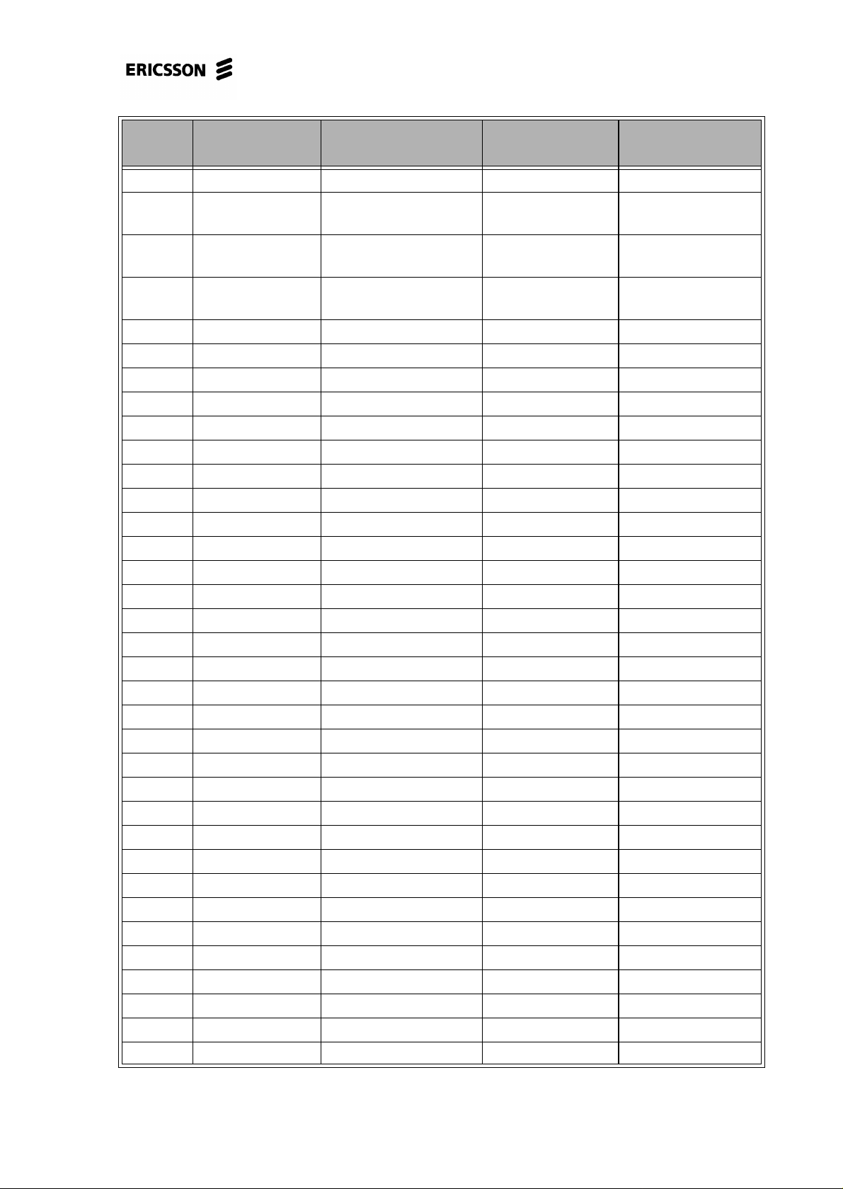
PF768, Standard Electrical Repairs
Trouble shooting
Positon Designation Part No. NOTE
instruction
N703 MICROCIRCUIT RYT 113 6040/5C Doesn't start
N705 MICROCIRCUIT RYT 113 048/C Verify SIM func-
tion
N706 MICROCIRCUIT RYT 113 6071/5 Verify Real Time
Clock function
N800 PROD. ADAPT.
Advanced Audio
CIRCUIT
R241 RESISTOR Advanced
R242 RESISTOR Advanced
R250 RESISTOR Advanced
R301 RESISTOR Advanced
R310 RESISTOR Advanced
R311 RESISTOR Advanced
R316 RESISTOR Advanced
R317 RESISTOR Advanced
R351 RESISTOR Advanced
R352 RESISTOR Advanced
R356 RESISTOR Advanced
R357 RESISTOR Advanced
SIM, Audio
Doesn't start
R358 RESISTOR Advanced
R400 RESISTOR Advanced
R401 RESISTOR Advanced
R402 RESISTOR Advanced
R407 RESISTOR Advanced
R411 RESISTOR Advanced
R450 RESISTOR Advanced
R452 RESISTOR Advanced
R454 RESISTOR Advanced
R455 RESISTOR Advanced
R456 RESISTOR Advanced
R458 RESISTOR Advanced
R459 RESISTOR Advanced
R468 RESISTOR Advanced
R469 RESISTOR Advanced
R471 RESISTOR Advanced
R473 RESISTOR Advanced
R503 RESISTOR Advanced
R505 RESISTOR Advanced
4/00021-2/FEA 209 544/11.C 61 (68)
Page 62

PF768, Standard Electrical Repairs
Positon Designation Part No. NOTE
R506 RESISTOR Not available
R521 RESISTOR Advanced
R553 RESISTOR Advanced
R562 RESISTOR Advanced
Trouble shooting
instruction
R600 RESISTOR REP 622 452/33 Verify SIM func-
tion
R601 RESISTOR REP 622 454/1 Verify portable
handsfree function
R602 RESISTOR REP 622 453/47 Verify vehicle
handsfree function
R604 RESISTOR REP 622 455/22 Verify flash func-
tion
R605 RESISTOR REP 622 454/1 Verify vehicle
handsfree function
R607 RESISTOR REP 622 454/1 Verify Illumination
function
R608 RESISTOR REP 622 454/15 Verify Illumination
function
R609 RESISTOR REP 622 452/33 Verify Illumination
function
R610 RESISTOR REP 622 452/33 Verify Illumination
function
R611 RESISTOR REP 622 001/0 Verify Illumination
function
SIM
Audio
Audio
Illumination and
Buzzer
Illumination and
Buzzer
Illumination and
Buzzer
Illumination and
Buzzer
R612 RESISTOR REP 622 001/0 Verify Illumination
function
Illumination and
Buzzer
R613 RESISTOR REP 622 455/1
R615 RESISTOR REP 622 455/1 Verify display
Display
function
R616 RESISTOR REP 622 455/1 Verify display
Display
function
R617 RESISTOR REP 622 455/15
R619 RESISTOR REP 622 454/22 Display
R620 RESISTOR REP 622 454/22 Display
R621 RESISTOR REP 622 455/1
R622 RESISTOR REP 622 454/1 Verify external
equipment function
R625 RESISTOR REP 622 453/47 Verify external
equipment function
R626 RESISTOR REP 622 456/18 Verify SIM func-
tion
4/00021-2/FEA 209 544/11.C 62 (68)
Page 63

PF768, Standard Electrical Repairs
Positon Designation Part No. NOTE
Trouble shooting
instruction
R627 RESISTOR REP 622 001/0 Verify SIM func-
tion
R628 RESISTOR REP 622 453/1 Verify SIM func-
tion
R629 RESISTOR REP 622 456/1
R630 RESISTOR REP 622 456/1 Verify keyboard
function
R631 RESISTOR REP 622 456/1 Verify keyboard
function
R632 RESISTOR REP 622 456/1 Verify keyboard
function
R633 RESISTOR REP 622 456/1 Verify keyboard
function
R634 RESISTOR REP 622 456/1 Verify keyboard
function
R635 RESISTOR REP 622 455/22 Verify vehicle
handsfree function
R636 RESISTOR REP 622 455/22 Verify portable
handsfree function
R642 RESISTOR Advanced
SIM
SIM
Keyboard
Keyboard
Keyboard
Keyboard
Keyboard
Audio
Audio
R643 RESISTOR Advanced
R644 RESISTOR Advanced
R645 RESISTOR Advanced
R646 RESISTOR REP 622 453/33 Verify green top
LED
R647 RESISTOR REP 622 453/33 Verify red top LED
R650 RESISTOR REP 622 456/1 Verify external
equipment function
R651 RESISTOR REP 622 454/1 Verify buzzer func-
tion
R652 RESISTOR REP 622 451/47 Verify buzzer func-
tion
R653 RESISTOR REP 624 001/0 Verify buzzer func-
tion
R656 RESISTOR REP 622 001/0
R700 RESISTOR REP 622 456/1 Verify On/Off func-
tion
R704 RESISTOR REP 622 456/1 Verify SIM func-
tion
Illumination and
Buzzer
Illumination and
Buzzer
Illumination and
Buzzer
R706 RESISTOR REP 622 451/47 Verify SIM func-
tion
4/00021-2/FEA 209 544/11.C 63 (68)
SIM
Page 64

PF768, Standard Electrical Repairs
Positon Designation Part No. NOTE
R708 RESISTOR REP 622 456/1 Verify On/Off func-
tion
R709 RESISTOR REP 622 454/47 Verify On/Off func-
tion
R710 RESISTOR REP 622 656/1
R711 RESISTOR REP 622 656/1
R719 RESISTOR REP 622 455/47 Verify Real Time
Clock function
R720 RESISTOR REP 622 456/18 Verify Real Time
Clock function
R724 RESISTOR REP 624 652/47 Verify external
equipment function
R725 RESISTOR REP 622 456/1
R802 RESISTOR REP 622 654/39 Verify handsfree
mic function
Trouble shooting
instruction
SIM
Audio
R803 RESISTOR REP 622 453/1 Verify handsfree
Audio
earphone function
R804 RESISTOR REP 622 456/1 Verify handsfree
Audio
earphone function
R805 RESISTOR REP 622 655/15 Verify handsfree
Audio
mic function
R807 RESISTOR REP 622 655/68 Verify display
function
R808 RESISTOR REP 622 656/1 Verify display
function
R812 RESISTOR REP 622 653/47 Verify mic function
R814 RESISTOR REP 622 653/47 Verify mic function
R815 RESISTOR REP 622 656/1
R816 RESISTOR REP 622 453/47 Verify mic function Audio
R817 RESISTOR REP 622 454/1 Verify mic function Audio
R818 RESISTOR REP 622 455/22 Verify mic function
R819 RESISTOR REP 622 454/1 Verify mic function Audio
R820 RESISTOR REP 622 653/47 Verify mic function
R822 RESISTOR REP 622 456/1
R823 RESISTOR REP 622 456/1
R825 RESISTOR REP 622 654/33 Verify handsfree
mic function
R830 RESISTOR REP 622 453/47 Verify handsfree
mic function
R831 RESISTOR REP 622 455/1
R832 THERMISTOR REZ 401 055/1
4/00021-2/FEA 209 544/11.C 64 (68)
Audio
Audio
Page 65

PF768, Standard Electrical Repairs
Positon Designation Part No. NOTE
R900 RESISTOR REP 622 455/1
R901 RESISTOR REP 622 455/1
R902 RESISTOR REP 622 455/1
R903 RESISTOR REP 622 455/1
R904 RESISTOR REP 622 454/1
R905 RESISTOR REP 622 455/1
R907 RESISTOR REP 622 456/1
R908 RESISTOR REP 622 456/1
R909 RESISTOR REP 622 456/1
R910 RESISTOR REP 622 455/1
Trouble shooting
instruction
S820 PUSH-BUTTON
RMD 955 101/01 Keyboard
SWITCH2
S821 PUSH-BUTTON
RMD 955 101/01 Keyboard
SWITCH2
U200 TRANSFORMER Advanced
U201 TRANSFORMER Advanced
V300 TRANSISTOR Advanced
V301 TRANSISTOR Advanced
V302 TRANSISTOR Advanced
V350 TRANSISTOR Advanced
V351 TRANSISTOR Advanced
V420 DIODE Advanced
V421 DIODE Advanced
V430 TRANSISTOR Advanced
V450 TRANSISTOR Advanced
V452 TRANSISTOR Advanced
V552 DIODE Advanced
V605 DIODE RKZ 123 647/1 Verify buzzer func-
tion
V606 TRANSISTOR RYN 121 6086/1 Verify buzzer func-
tion
V607 TRANSISTOR RYN 121 6069/1 Verify flash func-
tion
V608 DIODE RKZ 123 646/1 Verify display
function
V609 DIODE RKZ 323 673/1 Verify SIM func-
tion
V613 TRANSISTOR RYN 121 6086/1 Verify Illumination
function
4/00021-2/FEA 209 544/11.C 65 (68)
Illumination and
Buzzer
Display
Page 66

PF768, Standard Electrical Repairs
Positon Designation Part No. NOTE
V614 TRANSISTOR RYN 121 6086/1 Verify Illumination
function
V700 TRANSISTOR RYN 122 625/1 Verify SIM func-
tion
V701 TRANSISTOR RYN 121 6069/1 Verify On/Off func-
tion
Trouble shooting
instruction
SIM
V702 DIODE RKZ 123 647/1 Verify On/Off func-
Doesn't start
tion
V703 TRANSISTOR RYN 121 6069/1
V704 TRANSISTOR RYN 120 647/1 Verify On/Off func-
Doesn't start
tion
V705 TRANSISTOR RYN 120 647/1 Verify SIM func-
tion
V706 TRANSISTOR RYN 121 6086/1 Verify buzzer func-
tion
V708 TRANSISTOR RYN 121 6069/1 Verify On/Off func-
Illumination and
Buzzer
Doesn't start
tion
V709 TRANSISTOR RYN 121 6069/1 Verify On/Off func-
Doesn't start
tion
V711 DIODE RKZ 123 647/1 Verify Real Time
Doesn't start
Clock function
V805 DIODE RKZ 123 646/2 Verify mic function
X810 CONNECTOR2 SXA 120 5152 Audio
Z200 FILTER Advanced
Z201 FILTER Advanced
Z400 FILTER Advanced
Z500 FILTER Advanced
4/00021-2/FEA 209 544/11.C 66 (68)
Page 67

PF768, Standard Electrical Repairs
10.3 Mounting drawing table
Boardpartnr2/ROA 117 3235/2 R1A, R1B, R2A, R2B, R3A R4A, R4B, R4C.
Mounting
drawing
1078-2/ROA 117 3235/2 Rev C Rev E
10.4 Revision change table
10.4.1 Rev. change tab 1
Pos 2/ROA 117 3235/2 Part number
R-state
C670 up to R4B not mounted
R4C RJC 463 3022/1
C690 up to R4B RJC 463 3022/1
R4C RJC 463 3022/12
C691 up to R4B RJC 463 3022/1
R4C RJC 463 3022/12
F601 up to R4A REY 203 03/3
R4B, R4C REY 203 08/1
4/00021-2/FEA 209 544/11.C 67 (68)
Page 68

PF768, Standard Electrical Repairs
4/00021-2/FEA 209 544/11.C 68 (68)
 Loading...