

Page 1
LBI-38955A
Operator’s Manual
PCS™
STANDARD/SCAN/DTMF
PORTABLE RADIO
ericssonz
Page 2

TABLE OF CONTENTS
Page
INTRODUCTION...................................................4
CONTROLS...........................................................7
SCAN CONTROLS................................................13
INDICATORS.........................................................14
CHANNEL AND VOLUME INDICATORS ..........15
STATUS INDICATORS......................................17
ALERT TONES ...................................................18
POWER-UP SELF-TEST...................................19
CARRIER CONTROL TIMER.............................19
CHANNEL BUSY LOCK-OUT............................19
RECEIVE-ONLY CHANNEL...............................20
TYPE 99 ALERT TONE......................................20
ANI ALERT TONE..............................................20
PRIORITY-ONE (P1) SCAN...............................21
RADIO/CHANNEL FAILURE..............................21
OPERATION..........................................................21
RECEIVING A MESSAGE..................................21
SENDING A MESSAGE.....................................23
TYPE 99 OPERATION.......................................23
This manual is published by
Improvements and changes to this manual necessitated by
typographical errors, inaccuracies of current information, or
improvements to programs and/or equipment, may be made by
Ericsson Inc.
incorporated into new editions of this manual. No part of this manual
may be reproduced or transmitted in any form or by any means,
electronic or mechanical, including photocopying and recording, for
, at any time and without notice. Such changes will be
Ericsson Inc.
, without any warranty.
any purpose, without the express written permission of
Copyright © November 1993, Ericsson GE Mobile Communications Inc.
2
Ericsson Inc.
Page 3

TABLE OF CONTENTS (Con’t)
Page
SCAN OPERATION ...........................................25
TELEPHONE INTERCONNECT CALLS............27
∆
OR "H" BUTTON OPERATION.......................32
BATTERY PACKS.................................................34
INSTALLING THE BATTERY PACK..................34
REMOVING THE BATTERY PACK ...................35
CHARGING THE BATTERY PACKS.................36
RECHARGEABLE BATTERY PACK
DISPOSAL...................................................38
INTRINSICALLY SAFE USAGE............................38
BATTERY PACKS..............................................39
ACCESSORIES..................................................39
SWIVEL MOUNT REMOVAL AND
REPLACEMENT .............................................40
OPERATING TIPS.................................................41
3
Page 4

INTRODUCTION
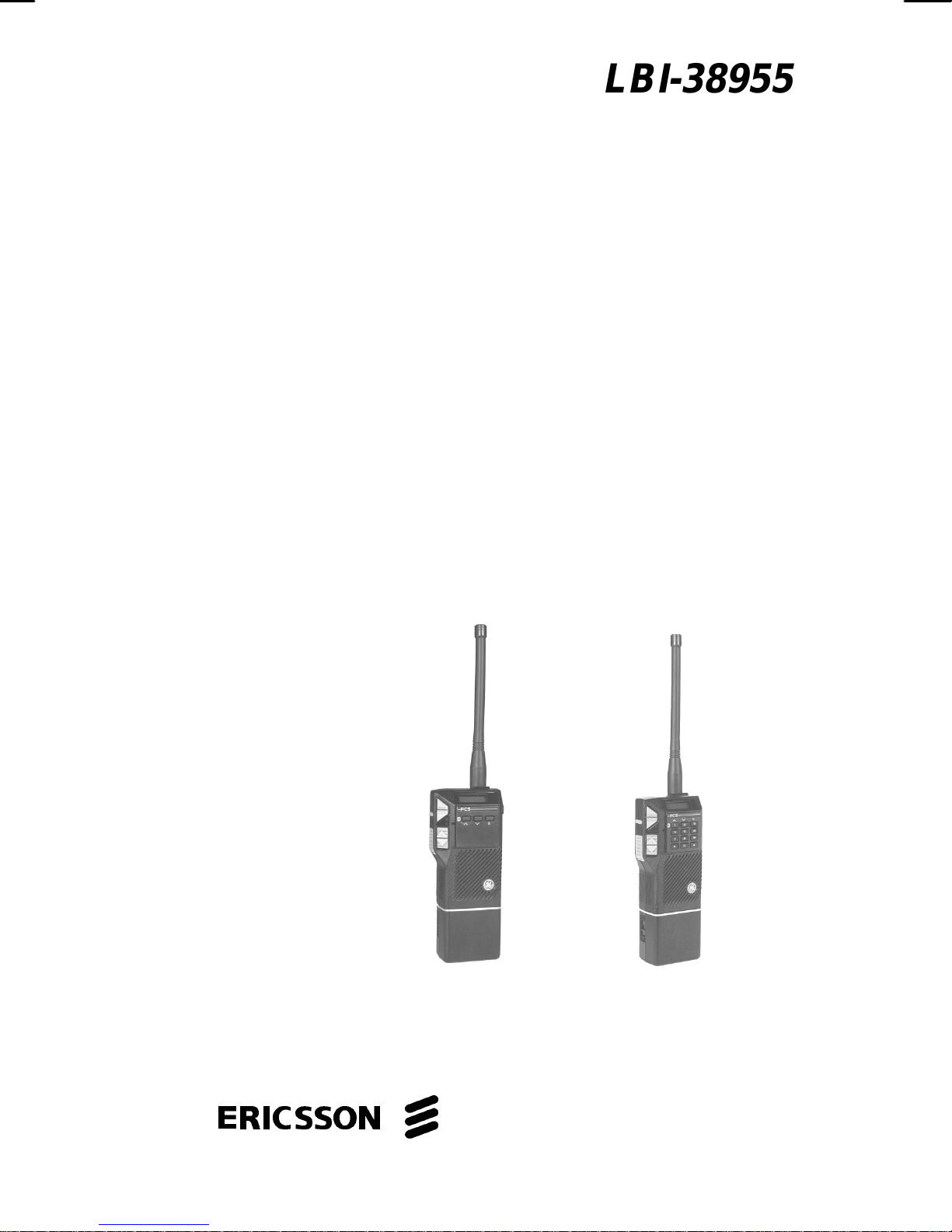
The PCS™ Standard/Scan/DTMF portable radios
are lightweight, full-featured radios that provide reliable
two-way communic ations. The PCS com es in 2-, 8-, and
16-channel versions. The SCAN func tion exists on the 8and 16-channel radios and allows monitoring of all
channels. Any channel may be scanned with or without a
priority level. One channel can be programmed for
Priority 1 (P1) and another for Priority 2 (P2), with any or
all remaining channels programmed as non-priority
channels. It also allows HOME channel selection or
Emergency mode transmission.
The User (also known as Universal) Device
Connector (UDC), located on the side of the radio,
provides connections for external audio accessories.
This connector als o allows the radio system personnel to
connect programming equipment and program the perchannel and overall radio features. Consult the radio
system personnel to determine the programmed features
of your radio. Features that are programmable on a perchannel basis include:
• Receive Frequency
• Transmit Frequency
• High/Low Transmit Power
• Channel Busy Lock-Out
• Squelch Tail Elimination (STE)
4
Page 5

• Channel Guard Encode/Decode (Tone or Digital)
• Type 99 Tone Decode
• Automatic Number Identification (ANI)
• Telephone Interconnect (DTMF Dial)
Features that are programmable on an overall radio
basis include:
• Carrier Control Timer (CCT)
• Display Backlighting
• Alert Tones
• HOME Channel or Emergency Channel (on
SCAN versions)
• Three (3) Auto-Dial Telephone Numbers (on
SCAN versions)
5
Page 6
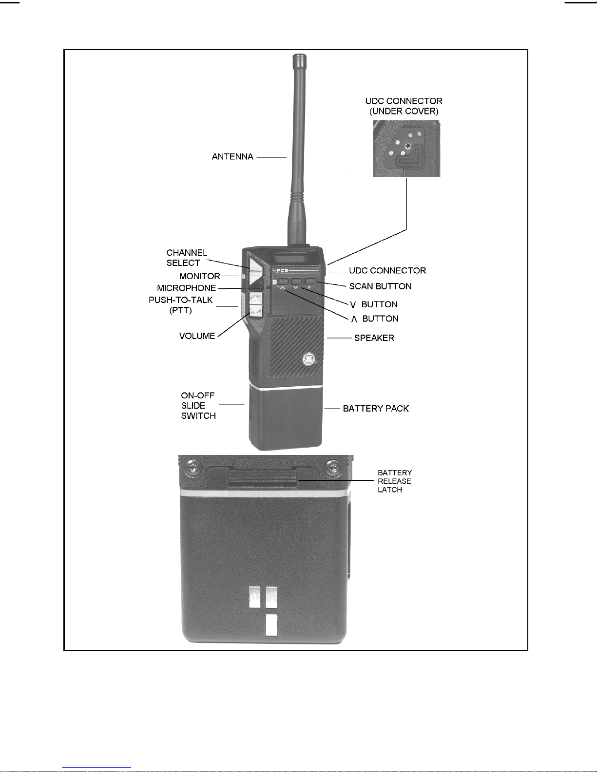
Figure 1 - PCS Standard/Scan Radio
6
Page 7
CONTROLS
ON/OFF SWITCH
The ON/OFF switch is located
on the battery pack. Sliding this
switch up to the "ON" position will
supply power to the radio from the
battery pack. An audible "click"
will be heard.
When the radio is turned on, it
will resume operation at the last
operating state (channel, volume,
etc.) and the power-up alert tones
will be sounded. Three (3) beeps
indicate the radio is in the norm al
(receive mode); four (4) beeps
indicate the radio is scanning.
PTT BUTTON
(Push-to-Talk)
The operating status of the radio
will be displayed in the Liquid
Crystal Display (LCD) window.
Pressing the PTT button on
the side of the radio will key the
radio transmitter.
If the radio is not scanning, it
will transmit on the selected
(displayed) channel. If the radio is
scanning when the PTT button is
pressed, the radio may be
programmed to transmit on the
Continued ...
7
Page 8

PTT BUTTON
selected channel or on the current
(Push-to-Talk)
(cont'd)
MONITOR
BUTTON
receive SCAN channel.
If the selected channel is programmed with Type 99 Tone
Decode enabled, pressing the
PTT button will disable Type 99
Tone Decode by switching the
radio from the Selective Call
mode to the Monitor mode. The
PTT button m ust be released and
then pressed a second time to
key the radio.
The MONitor button has several functions. Its operation will
vary depending upon programming.
If the MONitor button is programmed for "squelch" operation,
pressing it unsquelches the
receiver for the first three (3)
seconds the button is held. All
transmis sion will be heard, even if
Channel Guard protected. This
allows channel monitoring before
transmitting. If the button is held
for more than three (3) seconds,
Channel Guard decode will toggle
ON or OFF (if it is programmed
8
on the selected channel).
Continued ...
Page 9

MONITOR
If the MONitor button is pro-
BUTTON
(cont'd)
grammed for "Channel Guard"
operation, pressing and releasing
it within one (1) second will toggle
Channel Guard ON or OFF.
Pressing and holding for more
than one (1) second will
unsquelch the receiver after one
(1) second and allow channel
monitoring as long as the button
is held; Channel Guard status will
not be affected.
The MONitor button is also
used to reset the radio after a
Type 99 call is received. Quickly
VOLUME
CONTROLS
press and release the button to
reset the radio to receive the next
Type 99 call.
The speaker volume level is
controlled by the two buttons on
the side of the radio. Pressing the
VOLUME UP (∆∆) button will
increase volume and press ing the
VOLUME DOWN (∇∇) button will
decrease the volume. T he relative
volume level is indicated in the
LCD window by four (4) bars.
Continued ...
9
Page 10

VOLUME
The relative volume level is indi-
CONTROLS
(cont'd)
CHANNEL
SELECTION
cated in the LCD window by four
(4) bars. There are eight levels of
volume. Two levels of volum e are
represented by each bar.
Changing the volume while
the radio is squelched will cause
the radio to beep, if program med,
at the new selected level. No
beep is sounded if the radio is unsquelched.
Select the transmit/receive
channel by pressing the
CHANNEL UP (∆∆) or the
CHANNEL DOWN (∇∇) button.
The channel number will be
displayed in the LCD window.
Press the CHANNEL UP button to
increase the channel and press
the CHANNEL DOWN button to
decrease the channel. Channel
selection will wrap around
(Channel 1 follows Channel 16 [or
Channels 2 or 8] when increasing
channels; Channel 16 [or 2 or 8]
follows Channel 1 when decreasing channels).
10
Page 11

The three (3) buttons (top three on the DTMF
keypad) are used to control a variety of operations when
used alone and to control SCAN operations when used
in conjunction with the "S" button on the 8- and 16-
channel radios. Details are as follows:
NOTE
These three buttons are also used to place telephone
calls ("1" - "3" digits) when the telephone
interconnect feature is enabled. In addit ion, the "∆"
UP ARROW button (HOME or digit "1") selects the
HOME/EMERGENCY channel (on the SCAN
versions).
H
∆∆
The ∆∆ or "H" button allows the
following (see SCAN Controls for
further details):
1. Add channels to Scan list when
used in conjunction with the "S"
1
button (for 8- and 16-channel
radios). SCAN must be off when
adding channels.
2. Programming of a HOME or
EMERGENCY channel (when used
alone). This applies only to SCAN
versions.
3. BACKLIGHT the LCD (for 2-
channel radios). The backlight will
Continued ...
11
Page 12

∆∆
(Cont'd)
stay on as long as the button is
pressed and will remain on for five
(5) seconds after the button is
released, providing the button was
held for at least one second.
"S"
S
3
∇∇
Pressing the "S" button will turn
the SCAN function on and off (8- or
16-channel radios ). For 2-channel
radios, this button functions as an
on/off switch for Talk Around mode.
When in Talk Around mode, the
radio will transmit on the programmed receive frequency with
the receive Channel Guard (if programmed).
Pressing the ∇∇ button allows
you to delete a channel(s) when
used in conjunction with the "S"
button (8- and 16-channel radios).
2
12
On the 2-channel radio, this button
is the POWER SET button.
Pressing this button toggles the TX
power between the high and low
setting if the feature is enabled by
the PC programmer.
Page 13

SCAN CONTROLS
Holding the "S" button and then pressing ∆∆ or ∇∇ keys
(buttons) enables the following functions. (These
functions apply only to the 8- and 16-channel radios.)
∆∆
Holding the "S" button while
pressing the ∆∆ button will add the
selected channel to the Scan list.
Repeating this sequence will toggle
SCAN status between non-priority
SCAN, Priority 2 SCAN, and
Priority 1 SCAN. W hen a channels'
SCAN status is changed, the status
indicators in the LCD window will
be updated. If a new Priority 1 or
Priority 2 channel is selected, the
previous corresponding Priority
channel will become a non-priority
channel.
∇∇
SCAN must be off to add or delete channels from the
Scan list. (See the SCAN operating procedures for more
information.)
Holding the "S" button while
pressing the ∇∇ button will delete the
selected channel from the Scan list.
The SCAN Priority status indicator
in the display window will turn off.
13
Page 14

DTMF KEYPAD
Telephone Interconnect calls can
be placed using the 12-button
DTMF keypad option. This keypad
is enabled when a DTMFprogrammed channel is selected
and the PTT button is pressed.
See the telephone interconnect
operating procedures and Figure 2
for more details.
HOME CHANNEL
SELECTION/
EMERGENCY
MODE
The HOME/EMERGENCY button,
located on the 12-button DTMF
keypad (digit "1" or H) can be
programmed as a HOME channel
button or as an EMERGENCY
button. See the HOME/
EMERGENCY button operating
procedures for more details.
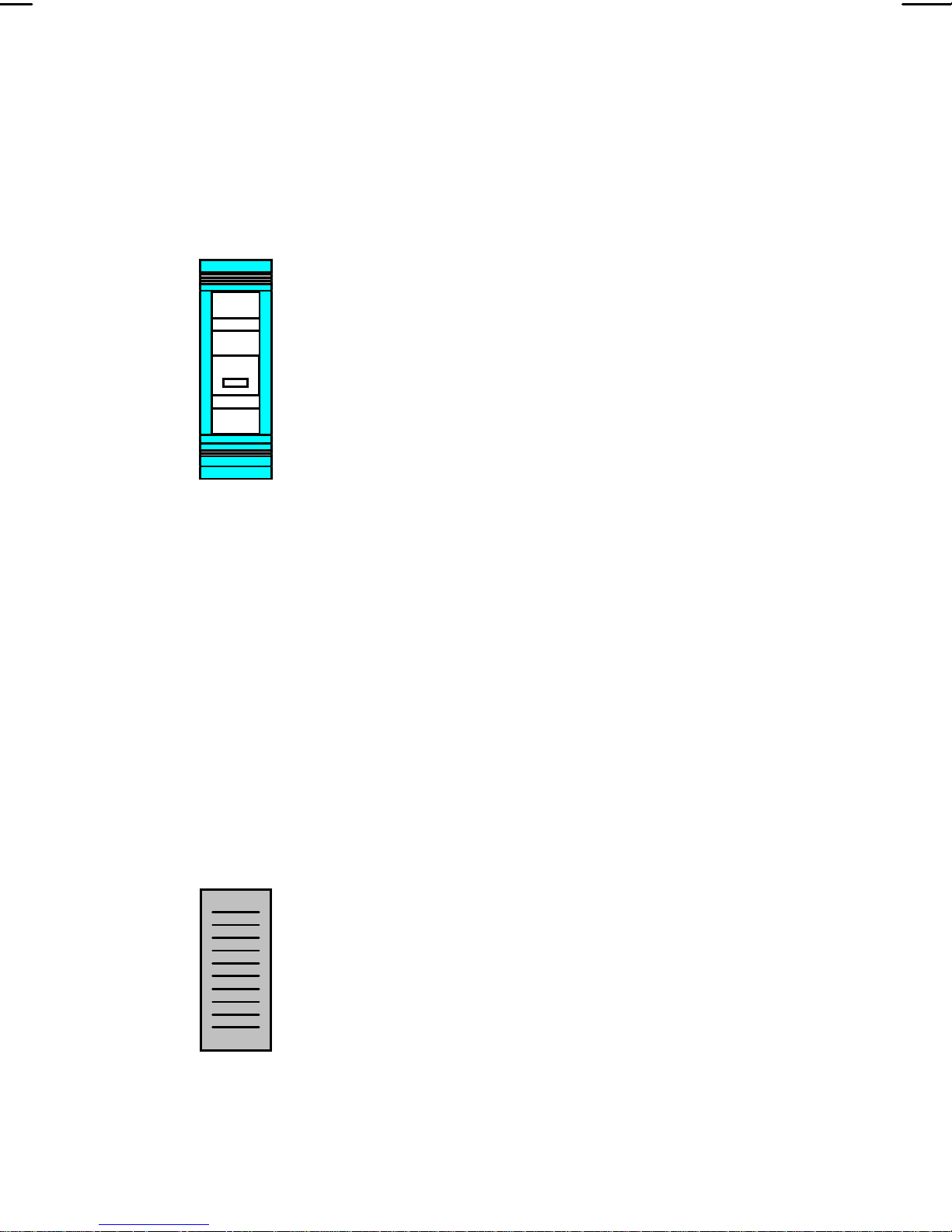
INDICATORS
The Liquid Crystal Display (LCD) indicates the
channel number and volume. In addition, seven (7)
status indicators show SCAN status, Type 99 Tone
Decode status, transmitter keyed, and a low battery
condition. (See Figure 3.)
LCD backlighting will turn on anytime a control button
is pressed. It will remain on for f ive (5) seconds after the
button is released. Backlighting m ay be programmed to
remain off at all times.
14
Page 15

(For 2-channel radios the ∆∆ or 'H' button is
programmed to turn on backlight for as long as the
button is pressed, remaining illuminated for 5 seconds
after the button has been released, providing the button
is held for at least one second.)
CHANNEL AND VOLUME INDICATORS
The selected channel number is
displayed in the LCD window. In 2channel radios, the "P1" pixel will
be illuminated when high TX power
is selected, otherwise the "P2" pixel
will be lit to indicate a low TX power
setting. If programmed, the ∇∇
button will toggle the TX power
setting. If this feature is disabled
through programm ing, the "P1" and
"P2" pixels will not be displayed.
Changing the channel after setting
the TX power will cause the
EEPROM setting to be reloaded.
Current volume level is displayed
by the volume bars. The radio has
eight different volume levels which
are represented by four bars (2
levels per bar).
15
Page 16

Figure 2 - PCS Standard/Scan/DTMF Keypad
16
Page 17

STATUS INDICATORS
SCN
S
P1
This status indicator turns on
when the radio is scanning (8- or 16channel radios).
When this indicator is on, the
selected channel is a non-Priority
SCAN channel (for 8- or 16-channel
radios). When this indicator is lit in a
2-channel radio, it indicates a selec ted
channel is in Talk Around mode.
When this indicator is illuminated,
the selected channel is a Priority 1
SCAN channel. This applies to the 8and 16-channel radios only. On 2-
P2
channel radios, if this feature is
enabled, this indicator is lit when the
high TX power setting is selected.
When this indicator is on, the
selected channel is a Priority 2 SCAN
channel. This applies to the 8- and
16-channel radios only. On 2-channel
radios, if this feature is enabled, this
indicator is lit when the low TX power
setting is selected.
Continued ...
17
Page 18

\ | /
PG
/ | \
This status indicator will turn on
when the channel is programmed as a
paging channel (Type 99 Selective
calls). It will flash when the Selec tive call
mode has been disabled and the radio is
in Monitor mode.
TX
BAT
PG
TX
BAT
This status indicator turns on when
the radio is transmitting.
If the battery pack charge is low and
requires charging, this status indicator
will turn on.
P1
SCN
S
P2
Figure 3 - Liquid Crystal Display (LCD)
ALERT TONES
Alert tones or "beeps" are sounded when a button is
pressed and when the operating status of the radio
changes. All alert tones may be programmed off.
18
Page 19

POWER-UP SELF-TEST
Each time the radio is turned on it will perform a
power-up self-test. All display segments will turn on, and
after successful completion of the test, the radio will
change to the last operating state (c hannel, volume, etc.)
and sound three (3) or four (4) beeps. Three beeps
sound if the radio is operating in the norm al (not SCAN)
state. Four beeps will sound if the r adio is scanning. The
status will be indicated in the LCD. If the radio fails the
self-test, no beeps will be sounded.
CARRIER CONTROL TIMER
This feature, programmable on a per-channel basis,
prevents unnecessary channel traffic and radio damage
if the transmit tim er limit is exceeded. If the program med
timer tim es-out during a transm ission, the radio will beep
and stop transmitting. The beeping tone will continue
until the operator releases the PTT button. Releasing the
PTT button resets the timer.
CHANNEL BUSY LOCK-OUT
If the radio is receiving a signal when the PTT button
is pressed, a beep will warn the operator that the r adio is
receiving a carrier and the transmission will not occur.
The beep is sounded as long as the PTT button is
pressed. The channel-busy feature is programmable on
or off on a per-channel basis.
19
Page 20

Type 99 decode and Channel Busy Lock-Out are
mutually exclusive. If Channel Busy Lock-Out is
programmed, T99 decode will not occur.
RECEIVE-ONLY CHANNEL
If the selected channel is programmed for receiveonly, the radio will beep if a transmission is attempted.
TYPE 99 ALERT TONE
The Type 99 alert tone, indicating a receive Type 99
call, may be enabled or disabled by PC programming. If
the alert tone is enabled, the level may also be
programmed to sound at the present volume control
setting or at maximum volume, regardless of volume
control setting. If the alert tone is disabled, no alert tone
will be present when a Type 99 call is received.
ANI ALERT TONE
The ANI (Autom atic Number Identif ication) alert tone
beep can be enabled or disabled by PC programming. If
the alert tone is enabled, a beep will sound after the PTT
is pressed, to indicate to the user to begin voice
transmission. Some communication systems require a
time delay before voice transmission begins. If the alert
tone is disabled, no beep will be sounded.
20
Page 21

PRIORITY-ONE (P1) SCAN
If the radio receives a signal on the Priority 1 channel
when scanning, the radio will sound a beep if the Priority
1 alert tone is programmed on.
RADIO/CHANNEL FAILURE
The simultaneous flashing of the "BAT" status
indicator and the sounding of beeps indicates the
synthesizer is unable to correctly lock on the selected
channel. If this happens when transmitting, transmissions are inhibited (no transmission is made). Select
another channel, change the battery pack, or have the
radio repaired.
OPERATION
RECEIVING A MESSAGE
1. Turn the radio on by sliding the ON/OFF switch
on the battery pack to the "ON" position. A yellow
area will be visible. After the radio has
successfully completed its power-up self-test, it
will begin operation at the last operating state
(channel, volume, etc.). The operating status of
the radio will be displayed in the LCD window. If
programm ed on, the power-up alert tones (three
or four beeps) will be sounded.
21
Page 22

2. Select the desired operating channel by pressing
the CHANNEL UP or CHANNEL DOWN buttons.
The channel number will be displayed in the LCD
window.
3. When a message is received (and the correct
Channel Guard or Type 99 signal is decoded, if
programmed and enabled), the receiver will
unsquelch and the mes sage will be heard in the
speaker.
4. Adjust the volume as necessary.
NOTE
If the MONitor button is programmed for "squelch"
operation, pressing it unsquelches the receiver for the
first three (3) seconds the button is held. All
transmissions will be heard, even if Channel Guard
protected. If it is held for more than three seconds,
Channel Guard will toggle on or off (if it is
programmed for the selected channel).
If the MONitor button is programmed for "Channel
Guard" ope ration, press i ng an d releas ing it within one
(1) second will toggle Channel Guard on or off.
Press ing and holdi ng it for mor e t han one s econd will
unsquelch the receiver after one second to allow
channel monitoring as long as the button is held;
Channel Guard status will n o t be affecte d.
22
Page 23

SENDING A MESSAGE
1. Turn the radio on and select the desired
operating channel as described in "RECEIVING
A MESSAGE."
2. Press the MONitor button to determine if the
channel is in use. Never interrupt another
transmission.
3. Hold the radio so the antenna is vertical and
press and hold the PTT button when you are
ready to transmit. Speak directly into the grill or
across the face of the radio or external
microphone. Release the PTT button when you
are finished talking. Messages cannot be
received when the PTT button is pressed.
When transmitting on a paging channel (Type 99, if
programmed), the PTT button must be pressed
twice. The first press takes the radio out of Paging
mode. The second press keys the transmitter for
normal transmitter operation.
TYPE 99 OPERATION
The PCS Conventional/DTMF radio may be
NOTE
programmed to operate in the Selective mode or in the
Monitor mode when it is turned on. If the Selective mode
is programmed and a Type 99 channel is selected, the
23
Page 24

"PG" status indicator will illuminate (does not flash). If the
Monitor mode is program med and a Type 99 channel is
selected, the "PG" status indicator will flash.
W hen the radio is operating in the Selective m ode, it
operates as a tone and voice receiver and only those
calls that are coded for it will be heard.
W hen the radio is operating in the Monitor mode, all
calls (with the correct Channel Guard, if programmed)
will be heard.
In either mode, when a Type 99 channel has been
selected and a valid code is received, a series of beeps
will alert you of the incoming call. The "PG" status
indicator will flash at a slow rate. If the radio is in the
Selective mode, it will automatic ally switch to the Monitor
mode.
Type 99 Selective Call Receiving and Sending
1. Select the appropriate channel to receive the
Type 99 tone signal. The "PG" status indicator
will show in the display window.
2. After the Type 99 call is received and the beeps
are sounded, press the PTT button and answer
the call. When the communication sequence is
completed, press the MONitor button to reset the
radio for the next call.
3. When the radio is reset (Selective Call mode),
Type 99 operation can be disabled by pressing
24
Page 25

and releasing the PTT button. The "PG" indicator
will flash, indicating Monitor mode and the radio
will beep. No transmission occurs. A second
press of the PTT button will result in a normal
transmission.
4. To return to Type 99 Selective Call mode, press
the MONitor button. The "PG" status indicator
will stop flashing and turn on continuously.
SCAN OPERATION
(8- AND 16-CHANNEL RADIOS ONLY)
The PCS Conventional/DTMF radio may be
programmed for an operator-selectable SCAN and
Priority channel, a fixed Priority 1 channel, or a selected
channel Priority 1 channel. SCAN rate will vary
depending upon the number of channels on the Sc an list
and Channel Guard programming. Fewer channels on
the Scan list will result in a faster SCAN rate.
Adding Channels To and Deleting Channels From
the Scan List
1. SCAN must be off to add channels or delete
channels from the Scan list. If the "SCN" status
indicator is on, press the "S" button to turn SCAN
off.
2. Select the desired channel to be added to or
deleted from the Scan list.
25
Page 26

3. To add the channel, press and hold the "S"
button and then repeatedly press the ∆∆ or H
button until the desired Priority indicator appears:
"S" for non-priority, "P2" for Priority 2, or "P1" for
Priority 1.
4. If a new Priority 1 or Priority 2 channel is
selected, the previously corresponding priority
channel will become a non-priority SCAN
channel.
5. To delete a channel from the Scan list, press
and hold the "S" button and then press the ∇∇
button. The SCAN priority indicator will turn off.
Using SCAN
W hen SCAN mode is off, press and release the "S"
key to go into SCAN mode. SCAN mode will not be in
effect until the "S" key is released. The "SCN" status
indicator will turn on when the radio is scanning.
To exit SCAN mode, pres s and hold the "S" key for a
minimum of 1 second and then release.
If no priority channels are on the Scan list (or
programmed), the radio will scan in the manner indicated
in the following paragraphs. When a carrier is detected,
and, if programmed, the correct Channel Guard is
decoded, the display will indicate the detected channel
number. Scanning will stop and the radio will remain on
the channel until the carrier ceases. After the carrier
ceases, the radio will resume scanning.
26
Page 27

If a Priority channel(s) is on the Scan list (or
programm ed) the radio will scan in the following m anner.
The Priority 1, Priority 2, and then the non-priority
channels will be scanned. When a carrier is detected,
and, if programmed, the correct Channel Guard is
decoded, the LCD will indicate the channel number.
Sampling of the Priority 1 and Priority 2 channels will
continue. The radio will switch to a priority channel if a
priority channel carrier is detected, while a non-priority
channel is being received.
If the PTT button is pressed when SCAN is on, the
radio can be programmed to transmit on the selected
channel or on the current receive SCAN channel.
TELEPHONE INTERCONNECT CALLS
The keypad on the DTMF radio's front panel allows
the operator to make telephone interconnect calls on
radio systems equipped with this option. Telephone
numbers m ay be manually dialed, or one (1) of three (3)
programmed numbers can be selected and dialed
automatically. Most systems require an "*" to be sent at
the beginning of a transmission to get a dial tone.
Others require a "#." After the dial tone is received, the
number is sent.
Communication takes place in a simplex mode. In
other words, you cannot talk and listen at the sam e time.
You must press and hold the PTT button each time you
wish to talk (transmit) and release it when you wish to
listen (receive).
27
Page 28

At the completion of the call, m ost systems require a
"#" to be sent to disconnect the user from the telephone
system. Others require an "*".
Specific procedures for placing a telephone
interconnect call from the PCS DTMF radio are
determined by the radio system and the individual radio
programming. Consult a system representative for the
exact operating procedures necessary for your system
and radio.
12-Button DTMF Keypad
The top three (3) buttons on the 12-button DTMF
keypad are used for the following:
In 2-channel radios: a.) Backlight
b.) TX power toggle
c.) Talkaround
d.) Manually dialed
calls (digits 1-3)
In 8- and 16-channel
radios:
a.) Select an autodial
number
b.) Control SCAN
operation
c.) Select a Home/
Emergency Channel
d.) Manually dialed
calls (digits 1-3)
Except for these three (3) buttons, the keypad is
normally inactive. When placing a manually dialed call,
the DTMF keypad is active only when the PTT is pres sed
28
Page 29

and held. Automatically dialed calls do not require the
PTT button be held after the call sequence is started.
Placing a Manually Dialed Call
1. Select a channel in your radio system that has
telephone interconnect capability. The radio
should be programmed for DTMF operation on
this channel.
2. Press and hold the PTT button to key the
transmitter.
3. While holding the PTT button, press either the
"*" key or the "#" key, as required by the radio
system, to obtain a telephone line. The radio will
transmit the selected tone.
4. Release the PTT button and listen for a dial
tone.
5. When the dial tone is received, press and hold
the PTT button and dial the desired telephone
number. As you dial each digit and as the radio
transmits the DTMF tone, the DTMF sidetone
will be heard in the speaker.
6. Release the PTT button when the dial sequence
is complete.
7. When the called party answers, press and hold
the PTT button each time you wish to speak
29
Page 30

(transmit) and release it each time you wish to
listen (receive).
8. At the completion of the call, press and hold the
PTT button and then pres s the "#" or the "*" key
as the telephone interconnect system requires.
Release the PTT button.
Placing an Automatically Dialed Call
(8- and 16-Channel Radios Only)
(Number Programmed with a Preceding "*")
1. Select a channel in your radio system that has
telephone interconnect capability. The radio
should be programmed for DTMF operation on
this channel.
2. Press and hold the PTT button and then press
one of the channel buttons (CHANNEL UP or
CHANNEL DOW N). The radio will transm it for a
minimum of five (5) seconds. The PTT button
may be released after one of the channel
buttons has been pressed.
3. Press the button ("1," "2," or "3") corresponding
to the memory location (1, 2, or 3) of the
telephone number you wish to dial. The DTMF
sidetones will be heard in the speaker as the
radio transmits the DTMF tones. It is not
necessary to hold the PTT button while the radio
is automatically dialing the number.
30
Page 31

4. When the called party answers, press and hold
the PTT button each time you wish to speak
(transmit) and release it when you wish to listen
(receive).
5. At the completion of the call, press and hold the
PTT button and then press the "#" or "*" key as
required by the telephone interconnect system.
Release the PTT button.
Placing an Automatically Dialed Call
(8- and 16-Channel Radios Only)
(Number Not Programmed with a Preceding "*")
1. Select a channel in your radio system that has
telephone interconnect capability. The radio
should be programmed for DTMF operation on
this channel.
2. Press and hold the PTT button and then press
the "*" key. Release the PTT button and listen for
a dial tone.
3. After the dial tone is received, press and hold the
PTT button and then press one of the channel
buttons (CHANNEL UP or CHANNEL DOWN).
This action causes the radio to transmit for a
minimum of five (5) seconds. The PTT button
may be released after a channel button is
pressed.
4. Press the button ("1," "2," or "3") corresponding
to the memory location (1, 2, or 3) of the
31
Page 32

telephone number you wish to dial. The DTMF
sidetones will be heard in the speaker as the
radio transmits the DTMF tones. It is not
necessary to hold the PTT button while the radio
is automatically dialing a number.
5. When the called party answers, press and hold
the PTT button while you wish to speak
(transmit) and release it when you wish to listen
(receive).
6. At the completion of the call, press and hold the
PTT button and then press the "#" or "*" key as
required by the telephone interconnect system.
Release the PTT button.
∆∆ OR "H" BUTTON OPERATION
(8- and 16-Channel Radios Only)
The ∆∆ or "H" button, located on the 12-button DT MF
keypad (digit 1) can be programmed as a HOME channel
button, an EMERGENCY channel button, or can be used
to ADD channels to the Scan list (see SCAN
OPERATION). This applies only to the 8- and 16-channel
radios.
HOME Button Programmed
If programmed as a HOME button, pressing the "1"
key will instantly switch the radio to the programmed
HOME channel.
32
Page 33

Pressing the HOME button when the radio is
scanning will temporarily stop SCAN for five (5) seconds .
Pressing the PTT, CHANNEL UP, or CHANNEL DOW N
buttons within the five second interval will turn SCAN off
and the radio will remain on the HOME channel. The
radio will resume scanning if one of the above mentioned
buttons is not pressed within the five second interval.
EMERGENCY Button Programmed
If programmed as an EMERGENCY button and no
HOME channel is programmed, press and hold the
EMERGENCY button for at least one (1) second to
transmit the emergency ANI code on the selected
channel. If the radio is programmed with a HOME
channel, the emergenc y ANI code will be transmitted on
the HOME channel instead of the selected channel.
If the radio is scanning when the EMERGENCY
button is pressed and no HOME channel is programmed,
the radio will stop scanning, transm it the emergency ANI
code on the selected channel, and resum e scanning. If
the radio is scanning when the button is pressed and a
HOME channel is programmed, the radio will stop
scanning, transmit the emergency ANI code on the
HOME channel, switch receive operation to the HOME
channel, and resume scanning.
Emergency transmissions can only be disabled by
turning the radio off and then back on.
33
Page 34

The following battery packs are available for use with
the PCS radios:
BATTERY PACKS
PCPA1J
(19A705293P2)
PCPA1K
(19A705293P2)
Rechargeable Battery Pack,
High Capacity
Rechargeable Battery Pack,
Extra High Capacity
CAUTION
Battery packs used with the PCS radio must be
supplied by Ericsson Inc.
INSTALLING THE BATTERY PACK
34
1. Ensure the ON/OFF switch on the battery pack
is in the "OFF" position.
2. Hold the radio and the battery pack with the back
of them facing you. (See Figure 4.)
3. Align the grooves on the top of the battery pack
with the grooves on the bottom of the radio.
4. Slide the battery pack fully into the radio until the
battery release latch clicks into place.
Page 35

Figure 4 - Installing the Battery Pack
REMOVING THE BATTERY PACK
1. Ensure that the ON/OFF switch on the battery
pack is in the "OFF" position.
2. Press down on the battery release latch and
slide the battery pack out in the direction of the
release latch. (See Figure 5.)
35
Page 36

Figure 5 - Removing the Battery Pack
CHARGING THE BATTERY PACKS
After receiving a new battery pack from the factory, it
should be fully charged before placing it into service.
This also applies to battery packs that have been stored
for long periods of time. W hen the battery pack requires
charging, the "BAT" indicator in the LCD window will
illuminate and the radio will sound an alert tone.
There are several different styles of charger
available for the PCS radio and each has a different
charge rate. The battery packs may be charged with the
radio still connected or the battery pack can be
disconnected from the radio and charged alone. For
specific operating instructions regarding your charger,
refer to the applicable charger operating manual.
36
Page 37

Memory Effect in Nickel-Cadmium Batteries
Rechargeable batteries (nickel-cadmium) used with
the radio can develop a condition called "Memory Effect"
or reduced battery capacity. This condition occurs when
the battery is continuously overcharged for long periods
of time or when a regularly performed duty cycle allows
only a portion of the battery's capacity to be expended.
If the nickel-cadmium battery is only sparingly or
seldom used and/or is left on continuous charge for one
or two months at a time, it could develop "Memory
Effect." On the f irst discharging c ycle, the output voltage
could be reduced enough to minimize the battery's hours
of useful service. The most com mon method of causing
"Memory Effect" is regularly performing short duty cycles.
This is when the battery is operated so that only a portion
(50%) of its capacity is expended. This type of operation
can cause the battery to become temporarily inactive and
show a severe decrease in the ability to deliver at full
rated capacity.
Any nickel-cadmium battery showing signs of
reduced capacity should be checked for the "Memory
Effect" before being returned under warranty or being
scrapped. If it is determined that "Memory Effect" is the
probable cause, a procedure for reconditioning it should
be performed as follows:
1. A complete discharge (deep discharge) of the
battery should be made. This can be
accomplished by turning the radio "ON" and
allowing the battery to discharge overnight.
37
Page 38

2. A full charging cycle should be performed using
an appropriate Ericsson GE charger.
3. Repeat the preceding steps again. Performing
the deep discharge and charge cycle at least
twice should sufficiently restore the battery.
RECHARGEABLE BATTERY PACK DISPOSAL
The product you have purchased
contains a rechargeable battery. The
battery is recyclable. At the end of it's
useful life under various state and
local laws it may be illegal to dispose
of this battery into the municipal waste
stream. Check with your local solid
waste officials for details concerning
recycling options or proper disposal in
your area. Call Toll Free 1-800-8229362 for information and/or procedures for returning rechargeable
batteries in your state.
INTRINSICALLY SAFE USAGE
Selected portable radios with appropriate factory
installed F4 Options are certified as Intrinsically Safe by
the Factory Mutual Research Corporation. Intrinsically
Safe approval includes Class I, II, III, Division 1
hazardous locations in the presence of Groups C, D, E,
F and G atmospheres. Non-Incendive approval includes
38
Page 39

Class I, Division 2 hazardous locations in the presence of
Groups A, B, C and D atmospheres.
Hazardous locations are defined in the National
Electrical Code. Useful standards NFPA 437A and NFPA
437M for the classifications of hazardous areas can be
ordered from the National Fire Protection Association,
Batterymarch Park, Quincy, MA 02269.
BATTERY PACKS
Only battery packs identified with a green latch shall
be used with a portable radio that is rated and labeled as
Factory Mutual Intrinsically Safe. Use of nonspecified
battery packs voids Factory Mutual approval. The
following battery pack option is approved for use in
intrinsically safe radios.
PCPA1L Rechargeable Battery Pack
Extra High Capacity (Tall Case)
ACCESSORIES
The accessories that follow are approved for use
with intrinsically safe radios. Use of accessories other
than those listed voids Factory Mutual Approval.
PCAC1J Earpiece
PCAE1X Speaker/Microphone
PCNC1P Antenna, 136-174 MHz, Helical
PCNC3A Antenna, 403-470 Mhz, Whip
39
Page 40

PCNC3B Antenna, 470-512 MHz, Whip
PCNC3D Antenna, 440-470 Mhz, Helical
PCAC1C UDC Connector
PCZM1A Earpiece kit
PCHC5S Leather Case, with Swivel and Belt
Loop (Short Case)
PCHC5T Leather Case, with Swivel and Belt
Loop Antenna Retaining Strap (Short
Case)
PCHC5U Leather Case, with Swivel and Belt Loop
(Tall Case)
PCHC5V Leather Case, with Swival and Belt Loop
Antenna Retaining Strap (Tall Case).
PCHC1C Belt Clip
PCHC1D Swival Mount with Belt Clip
SWIVEL MOUNT REMOVAL AND REPLACEMENT
To remove the swivel mount, slide a flat blade
screwdriver underneath the spring retainer and twist.
W hile twisting, slide the swivel mount out from under the
holder. See Figure 6.
To Replace the swivel mount, place the end of the
swivel in the grooves in the back of the radio and slide
the mount up until it snaps into place.
40
Page 41

Figure 6 - Swivel Mount Removal and Replacement
OPERATING TIPS
Antenna location and condition are important when
operating a two-way radio. Operating the radio in low
terrain areas, under power lines or bridges, inside of a
vehicle, or inside a metal- or steel-framed building can
severely reduce the operating range of the unit.
Mountains and buildings can also reduce the range of
the unit.
In areas where transmission or reception is poor,
some im provement m ay be obtained by insuring that the
antenna is vertical. Moving a few yards in one direction
or another or moving to a higher elevation may also
improve communication.
41
Page 42

Battery condition is another important factor in the
trouble-free operation of the radio. Always properly
charge the batteries. (See Battery Packs section for
more information.)
Always observe all of the Federal Communication
Commission's (FCC's) rules and regulations.
NICKEL-CADMIUM BATTERY WARRANTY
A. Ericsson Inc. (hereinafter "Seller") warrants to the original purchaser for use (hereinafter
"Buyer") that nickel-cadmium batteries supplied by Seller shall be free from defects in
material and workmanship, and shall conform to its published specifications for a period of
twelve (12) months from the date of purchase.
B. For purposes of this warranty, batteries shall be deemed defective if (1) the battery capacity
is less than 80% of rated capacity, or (2) the battery develops leakage.
C. If any battery fails to meet the foregoing warranty, Seller shall correct the failure by issuing
a replacement battery upon receipt of the defective battery at an Authorized Service Center
(ASC). To obtain the name and address of an ASC, ask your salesperson, consult the
Yellow Pages, or call the number printed at the bottom of this page.
D. Replacement batteries shall be warranted only for the remaining unexpired warranty period
of the original battery. This warranty becomes void if:
(1) The battery has been subjected to any kind of misuse, detrimental exposure, or
has been involved in an accident.
(2) The battery is used in equipment or service other than the radio equipment for
which it is specified.
E. The preceding paragraphs set forth the exclusive remedies for claims (except as to title)
based upon defects in or non-conformity of any battery, whether the claim is in contract,
warranty, tort (including negligence), strict liability or otherwise, and however instituted. Upon
the expiration of the warranty period, all such liability shall terminate. The foregoing
warranties are exclusive and in lieu of all other warranties, whether oral, written, expressed,
implied or statutory. NO IMPLIED OR STATUTORY WARRANTIES OF MERCHANTABILITY
OR FITNESS FOR PARTICULAR PURPOSE SHALL APPLY. IN NO EVENT SHALL THE
COMPANY BE LIABLE FOR ANY INCI DENTAL, CONSEQUENTIAL, SPECI AL, INDIRECT
OR EXEMPLARY DAMAGES.
This warranty applies only within the United States.
42
ECX-841C
Page 43

WARRANTY
A.Ericsson Inc. (hereinafter "Seller") warrants to the original purchaser for use (hereinafter
"Buyer") that Equipment manufactured by Seller shall be free from defects in material,
workmanship and title, and shall conform to its published specifications. With respect to any
Equipment not manufactured by Seller (except for integral parts of Seller's Equipment to
which the warranties set forth above shall apply), Seller gives no warranty, and only the
warranty, if any, given by the manufacturer shall apply. Batteries are excluded from this
warranty but are warranted under a separate Nickel-Cadmium Battery Warranty.
B.Seller's obligations set forth in Paragraph C below shall apply only to failures to meet the
above warranties (except as to title) occurring within the following periods of time from date
of sale to the Buyer and are conditioned on Buyer's giving written notice to Seller within
thirty (30) days of such occurrence:
1. for fuses, incandescent lamps, vacuum tubes and non-rechargeable batteries, operable
on arrival only.
2. for parts and accessories (except as noted in B.1) sold by Seller's Service Parts
Operation, ninety (90) days.
3. for all other Equipment of Seller's manufacture, one (1) year.
C.If any Equipment fails to meet the foregoing warranties, Seller shall correct the failure at its
option (i) by repairing any defective or damaged part or parts thereof, or (ii) by making
available at Seller's factory any necessary repaired or replacement parts. Any repaired or
replacement part furnished hereunder shall be warranted for the remainder of the warranty
period of the Equipment in which it is installed. Where such failure cannot be corrected by
Seller's reasonable efforts, the parties will negotiate an equitable adjustment in price. Labor
to perform warranty service will be provided at no charge during the warranty period only for
the Equipment covered under Paragraph B.3. To be eligible for no-charge labor, service
must be performed by an Authorized Service Center or other Servicer approved for these
purposes either at its place of business during normal business hours, for mobile or
personal equipment, or at the Buyer's location, for fixed location equipment. Service on fixed
location equipment more than thirty (30) miles from the Service Center or other approved
Servicer's place of business will include a charge for transportation. Equipment located
outside the Continental United States is not eligible for no-charge labor.
D.Seller's obligations under Paragraph C shall not apply to any Equipment, or part thereof,
which (i) has been modified or otherwise altered other than pursuant to Seller's written
instructions or written approval or, (ii) is normally consumed in operation or, (iii) has a
normal life inherently shorter than the warranty periods specified in Paragraph B, or (iv) is
not properly stored, installed, used, maintained or repaired, or, (v) has been subjected to
any other kind of misuse or detrimental exposure, or has been involved in an accident.
E.The preceding paragraphs set forth the exclusive remedies for claims (except as to title)
based upon defects in or nonconformity of the Equipment, whether the claim is in contract,
warranty, tort (including negligence), strict liability or otherwise, and however instituted.
Upon the expiration of the warranty period, all such liability shall terminate. The foregoing
warranties are exclusive and in lieu of other warranties, whether oral, written, expressed,
implied or statutory. NO IMPLIED OR STATUTORY WARRANTIES OF
MERCHANTABILITY OR F ITNESS FOR PARTICULAR PURPOSE SHALL APPLY. IN NO
EVENT SHALL THE SELLER BE LIABLE FOR ANY INCIDENTAL, CONSEQUENTIAL,
SPECIAL, INDIRECT OR EXEMPLARY DAMAGES.
This warranty applies only within the United States.
1-800-528-7711 (Outside U.S.A. 804-528-7711) ECX-886A
43
Page 44

EMERGENCY NUMBERS
Police
State Police
Fire
Poison Control
Ambulance
Life Saving and
Rescue Squad
Ericsson Inc.
Private Radio Systems
Mountain View Road
Lynchburg, Virginia 24502
1-800-528-7711
(Outside USA, 804-528-7711) Printed in U.S.A.
 Loading...