

Page 1

NSP 6.1 Hardware Description
DESCRIPTION
1/1551-APR 901 0461/1 Uen M
Page 2

Copyright
© Ericsson AB 2011–2016. All rights reserved. No part of this document may be
reproduced in any form without the written permission of the copyright owner.
Disclaimer
The contents of this document are subject to revision without notice due to
continued progress in methodology, design and manufacturing. Ericsson shall
have no liability for any error or damage of any kind resulting from the use
of this document.
Trademark List
Xeon
Densishield
Sofix
is a trademark of Intel Corporation
is a trademark of FCI, Inc.
is a trademark of FCI, Inc.
1/1551-APR 901 0461/1 Uen M | 2016-04-19
Page 3

Contents
Contents
1 Introduction 1
2 Hardware Structure 3
2.1 Product Identification 5
2.2 Subracks 5
2.3 Ethernet Switching 6
2.4 Processor Boards 13
2.5 Meaning of the LEDs on the Front Panels of Plug-In Units 23
2.6 PTM (for PFM LODs only) 24
2.7 PFM 26
2.8 Active Patch Panel 31
2.9 Cables 33
3 Finding the Position of Units and Connectors 35
3.1 Positions at Cabinet Level 37
3.2 Positions at Subrack and Plug-in Unit Level 38
4 Hardware Configurations 41
4.1 First Installation 41
4.2 Cohabitation 44
4.3 Expansions 44
4.4 Board Allocation Order 45
5 Technical Data and Characteristics 49
5.1 Cabinet Dimensions 49
5.2 Weight 49
5.3 Power Supply 49
5.4 Power Consumption 54
5.5 Climatic Conditions 55
5.6 EMC 56
5.7 Product Safety 56
5.8 RoHS Compliance 56
5.9 Earthquake Resistibility 56
5.10 Acoustic Noise 56
5.11 Dependability 57
1/1551-APR 901 0461/1 Uen M | 2016-04-19
Page 4

NSP 6.1 Hardware Description
1/1551-APR 901 0461/1 Uen M | 2016-04-19
Page 5

1 Introduction
TSP hardware is called NSP while TSP refers to the complete system, both
hardware and software. This document describes NSP 6.1.
NSP 6.1 is based on the Ericsson Blade System (EBS) by using the same
concept, terminology, and the HW components, such as cabinets, subracks,
switch boards, and processor boards.
NSP 6.1 uses the following components:
• Core components of EBS
• Own node level HW management in TSP (no DMX support)
Introduction
• Only SCXB2/SCXB3 in subrack interconnection (no CMX support and no
Cabinet Aggregation Switch (CAX) support)
Note: The mixing of SCXB2 and SCXB3 boards in NSP 6.1 subrack is
only supported during hardware upgrade.
For more info on EBS, refer to Ericsson Blade System (EBS) Libraries.
1/1551-APR 901 0461/1 Uen M | 2016-04-19
1
Page 6

NSP 6.1 Hardware Description
2 1/1551-APR 901 0461/1 Uen M | 2016-04-19
Page 7

2 Hardware Structure
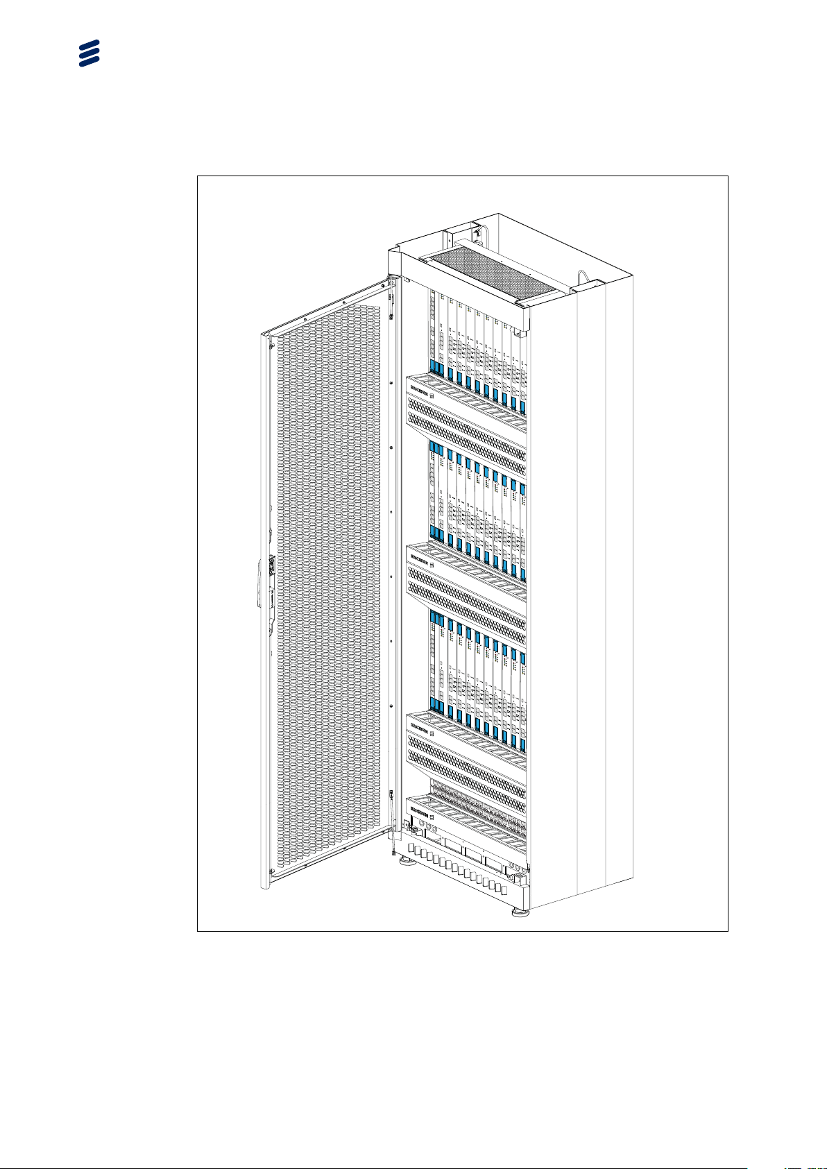
The NSP 6.1 consists of one BYB 501 cabinet, equipped with up to three
Evolved Generic Ericsson Magazine 2 (EGEM2) subracks. It has the
dimensions of 1800 × 600 × 400 mm (H × W × D). The doors can be locked.
Mounting kits for high earthquake risk areas are available.
A number of processors are inserted in each subrack. Up to three subracks
can be installed in a BYB 501 cabinet.
Note: From TSP 7100 release, NSP 6.1 cabinets are delivered with
pre-installed Power Termination Module (PTM) supporting Low Ohmic
power Distribution (LOD) for Power and Fan Modules (PFMs).
Hardware Structure
An example of a fully equipped NSP 6.1 node is shown in Figure 1.
The configuration of NSP 6 nodes is defined in product packages. No fixed
configurations are defined as platform configurations. The configurations that
are shown in this document are examples only.
The cabinets are designed for installation in indoor locations in
telecommunications centers.
The signaling interfaces of the system are designed for connection to other
indoor equipment. The system must not be directly connected to any outside
plant (OSP) cabling .
1/1551-APR 901 0461/1 Uen M | 2016-04-19
3
Page 8
NSP 6.1 Hardware Description
G
B
D
E
2
3
2
S
R
C
S
B
P
R
C
N
Y
S
2
E
G
1
E
G
4
E
3
E
2
E
1
E
G
B
D
E
2
3
2
S
R
CS
BP
R
C
N
Y
S
2
E
G
E
G
4
E1
3
E
2
E
1E
U
S
B
1
SA
T
A1
S
A
T
A-
U
0
/
SB
E
T
H
2
/
D
EB
U
G
CO
N
S
E
T
H
1
E
T
H
0
U
S
B
-
1
S
A
T
A-
1
S
A
T
A
-
U
0
/
S
B
E
T
H
-
2
/
D
E
BU
G
C
O
N
S
E
T
H
-1
ET
H
0
G
B
D
-
E
2
3
2
S
R
C
S
B
-
P
R
C
N
Y
S
U
S
B
-
1
S
A
2
T
A
-
E
1
S
A
T
A
-
0
US
1
/
B
E
G
E
T
H
-
2
/
D
E
B
U
G
CON
S
4
EG
3
E
E
TH-
1
2
E
E
T
H
-
0
1
E
S
S
7
A
/
B
S
S7
A
/
B
B
D
-
E
2
S
3
S
2
7
S
C
/
RG
D
S
S7
C
S
C
/
D
U
S
B
-
1
B
-
P
R
U
S
B
-
1
C
N
Y
S
S
U
A
S
T
B
A
-
-
1
1
S
A
T
A
S
-0
U
A
/
S
T
B
A
-
1
ET
S
A
H
T
-
A
SA
2
-
U
/
0/
D
2
S
T
E
B
A
B
E
-1
U
G
G
S
E
A
T
C
T
H
O
A
-
N
2
-
U
0
/
S
1
D
/
SB
E
B
E
U
G
G
E
T
C
H
O
-
2
N
/
D
S
E
B
U
G
E
C
T
O
H
N
-
1
S
4
E
E
T
E
H
T
-0
H
-
1
3
E
E
E
T
H
T
H
-0
-
1
2
E
E
T
H
-
0
1E
G
B
D
E
2
3
2
S
R
C
S
B
P
R
C
N
Y
S
U
S
B
2
1
E
G
1
E
G
S
A
T
A
1
S
A
T
A
-
U
0
/
S
B
4
E
E
T
H
-
2
/
D
E
B
U
3
G
E
C
O
N
S
2
E
1
E
E
T
H
1
E
T
H
-
0
G
B
D
-
E
2
3
2
S
R
C
S
B
-
P
R
C
N
Y
S
U
S
B
-
1
S
A
2
T
A
-
E
1
G
S
A
T
A
-
U
0
1
/
S
B
E
G
E
TH
-
2
/
D
E
B
U
G
C
O
N
S
4
E
3
E
E
TH
-
1
2
E
E
T
H
-
0
1
E
P021305A
Figure 1 Example of a Fully Equipped NSP 6.1 Cabinet
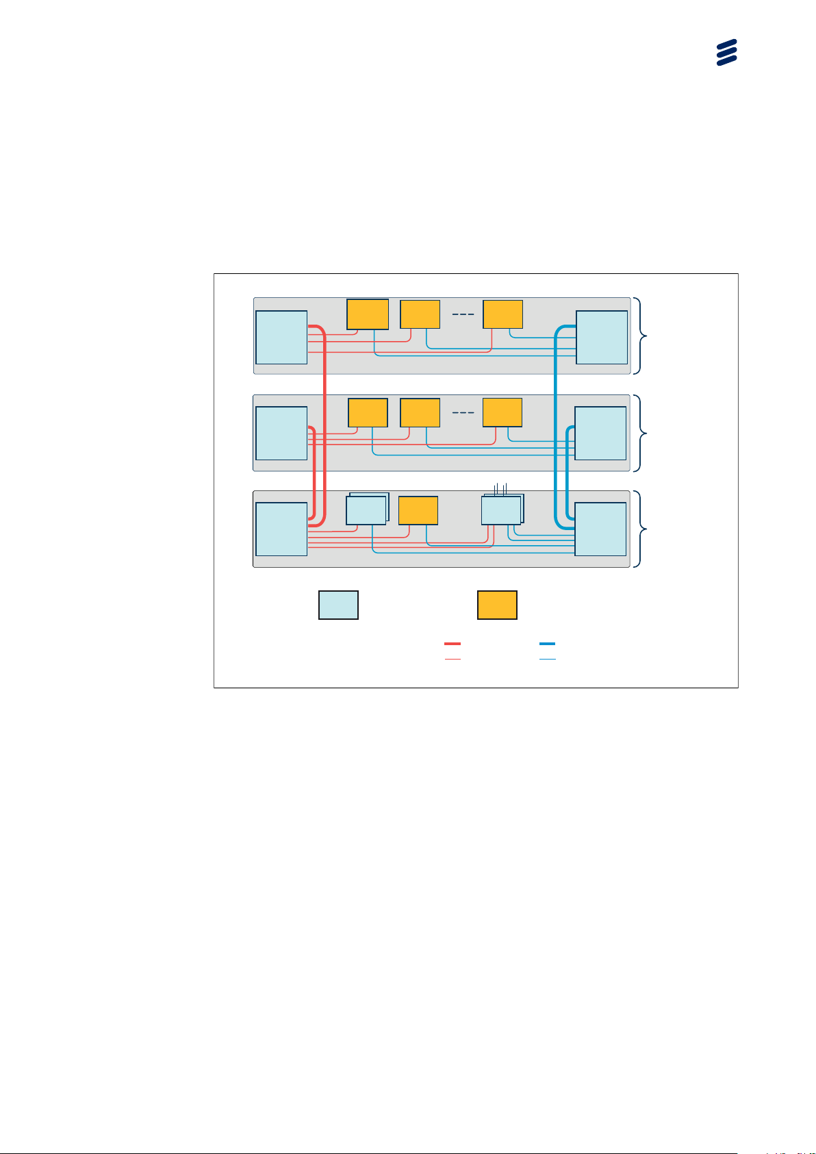
The cabinet contains one, two, or three subracks where the processors are
located. Each subrack can contain up to 12 processors. All processors in
a node are interconnected by duplicated internal Ethernet connections, see
Figure 2.
4
1/1551-APR 901 0461/1 Uen M | 2016-04-19
Page 9
Hardware Structure
P021697A
Note: A node consists of one, two or three subracks. If a node has more than
one subrack, these can be located in the same cabinet or in different
cabinets. It is also possible to locate more than one TSP node in the
same cabinet. This configuration is called cohabitation. For more
information see Section 4.2 on page 43.
Traffic
SCXB2 / SCXB3
Ethernet
Switch
Board
SCXB2 / SCXB3
Ethernet
Switch
Board
SCXB2 / SCXB3
Ethernet
Switch
Board
Traffic
Processor
Traffic
Processor
Processor
blade
SIS*
IO1
Processor
Processor
blade
Traffic
Processor
Processor
blade
Traffic
Processor
Processor
blade
IO, VIP, and Ethernet TSP TP
10G Ethernet, Network A Network B
1G Ethernet, Network A Network B
Figure 2 System Overview of NSP 6.1
Traffic
Processor
Processor
blade
Traffic
Processor
Processor
blade
ISE R*ISER
ISE R*VIP
SCXB2 / SCXB3
Ethernet
Switch
Board
SCXB2 / SCXB3
Ethernet
Switch
Board
SCXB2 / SCXB3
Ethernet
Switch
Board
Subrack 2
Subrack 1
Subrack 0
P021697A
2.1 Product Identification
All products are marked with product identification labels. The labels have two
parts, one giving the information in plain text and the other giving the same
information in two types of bar code: PDF 417 code and Code 128. Refer to
Identifying NSP 6 Hardware for more information. The product identification
information for plug-in units can also be retrieved electronically when the
system is operating.
2.2 Subracks
The EGEM2, BFD 538 002/1, is used in NSP 6.1.
Figure 3 shows the EGEM2 subrack.
1/1551-APR 901 0461/1 Uen M | 2016-04-19
5
Page 10
NSP 6.1 Hardware Description
Subrack address plug 0
Identification ROJ 119 2189/1
Subrack address plug 1
Identification ROJ 119 2189/1
Subrack address plug 3
Identification ROJ 119 2189/1
Address 00
Address 00
Address 00
Vertical position
marker
55
50
60
Horizontal position
65 70
marker
P021244A
Figure 3 EGEM2 Subrack with its Address Plugs
The main switch board used in the EGEM2 is called SCXB2 or SCXB3, based
on the board type the NSP hardware is equipped with, see Section 2.3 on
page 6 for more information.
In its basic configuration, apart from the two 15 mm width SCXB2 or SCXB3
plug-in units and the two 15 mm width dummy units, an EGEM2 can house up
to 12 plug-in units of 30 mm width. The plug-in units have the form factor of
265 × 225 mm. From the EGEM2 backplane, all plug-in units are provided with
dual –48 V
power supplies, duplicated 1000 Mb/s Ethernet connections, and
DC
Intelligent Platform Management Interface (IPMI) connections.
The subrack address is created by three address plugs at the left side of
EGEM2. The address can be read from all plug-in unit slots. The plugs are
inserted at the factory.
All plug-in units support hot-swapping.
Each EGEM2 subrack is equipped with two Power and Fan Modules (PFMs)
that provide cooling and power for the plug-in units in the subrack.
2.3 Ethernet Switching
The processors in an NSP 6.1 are interconnected by means of a duplicated
Ethernet based LAN. The interprocessor network is implemented as a
duplicated switched Ethernet.
6
1/1551-APR 901 0461/1 Uen M | 2016-04-19
Page 11

The subracks are connected in cascade, see Figure 2, and can be equipped
with SCXB2/SCXB3 types of system control switch boards.
Note: The mixing of SCXB2 and SCXB3 boards in NSP 6.1 subrack is only
2.3.1 SCXB2
There is only one level of Ethernet switching but two different bandwidths are
used:
• Subrack internal links have a bandwidth of 1 Gb/s.
• Intersubrack links have 10 Gb/s bandwidth.
The SCXB2 switch, ROJ 208 386/2, is used for Ethernet switching in the
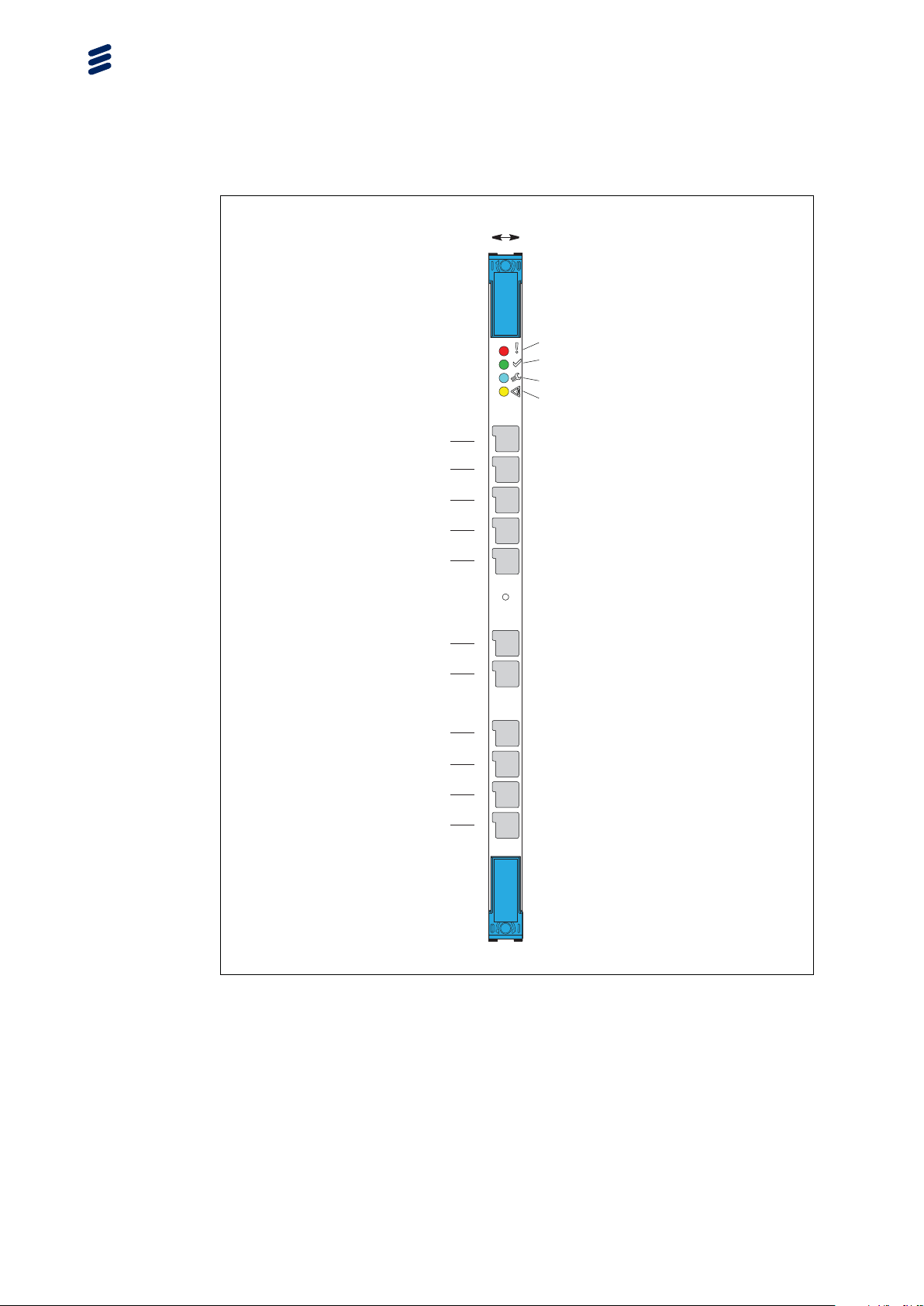
EGEM2 subracks in NSP 6.1. The SCXB2 switch is shown in Figure 4.
Hardware Structure
supported during hardware upgrade.
The SCXB2 is fed with –48V from the backplane.
1/1551-APR 901 0461/1 Uen M | 2016-04-19
7
Page 12
NSP 6.1 Hardware Description
Vertical
position
Y43
15mm
GBD-E232SRCS
Fault LED (red)
Operational LED (green)
Maintenance LED (blue)
Status LED (yellow)
Debug GE
Y40
Y38
Y35
Y33
Y25
Y23
Y18
Y15
Y13
Y10
Debug RS232/Alarm
Patch Panel
B
RP bus
-PRCNYS2 EG1 EG4E3E2E1E
Sync
GE 2
GE 1
10G 4
10G 3
10G 2
10G 1
P021396A
Figure 4 SCXB2 Front Panel
The SCXB2 plug-in unit provides the following functions:
• Ethernet switching:
10/100/1000 Mb/s Ethernet towards the backplane
10/100/1000Base-T Ethernet compatible at the front
8
1/1551-APR 901 0461/1 Uen M | 2016-04-19
Page 13
Hardware Structure
10G CX4 Ethernet compatible at the front
• Maintenance port:
10/100/1000Base-T Ethernet compatible at the front, for debug only
• IPMI Shelf Manager functions, based on SCX:
0
Monitoring of incoming power supply (A and B branches)
0
Fan monitoring
0
Monitoring of subrack address plugs
0
SNMP-based management of the Ethernet switches for troubleshooting
purposes
The SCXB2 plug-in units are 15 mm wide. Each EGEM2 subrack includes two
SCXB2 plug-in units for redundancy reasons. The SCXB2 units, with a 15 mm
wide dummy unit on the right-hand side of each, are placed at the leftmost and
the rightmost positions in EGEM2 subracks.
The on-board MPC 8544 processor runs the Linux operating system.
2.3.1.1 SCXB2 Front Interfaces
The connectors at the front of the SCXB2 are described in Table 1.
Table 1 SCXB2 Front Interfaces
Designation Interface
Debug GE
Debug RS232/Alarm
Patch Panel
RP bus
Sync
Comments
10/100/1000BASE-T For debug only
Console port, debug RS-232
For remote control of an
automatic Patch Panel
Used for supervising
the optional APPs in
the cabinet.
Serial Regional Processor
Not used in NSP
(RP) bus port
Clock Synchronization port Not used in NSP
GE 2
GE 1
10G 4
10G 3
10/100/1000BASE-T Not used in NSP
10/100/1000BASE-T Not used in NSP
Ethernet 10 Gb/s CX4
compatible
Ethernet 10 Gb/s CX4
compatible
10 Gb/s only, no
autonegotiation
10 Gb/s only, no
autonegotiation
91/1551-APR 901 0461/1 Uen M | 2016-04-19
Page 14

NSP 6.1 Hardware Description
Designation Interface
10G 2
10G 1
For details on front panel LEDs, see Section 2.5 on page 23.
2.3.2 SCXB3
The SCXB3 plug-in units provide the following functions:
• Subrack internal links have a bandwidth of 1 Gb/s.
• Intersubrack links have 10 Gb/s bandwidth.
The SCXB3 switch, ROJ 208 395/1, is used for Ethernet switching in the
EGEM2 subracks in NSP 6.1. The SCXB3 switch is shown in Figure 5.
The SCXB3 is fed with –48V from the backplane.
Ethernet 10 Gb/s CX4
compatible
Ethernet 10 Gb/s CX4
compatible
Comments
10 Gb/s only, no
autonegotiation
10 Gb/s only, no
autonegotiation
10
1/1551-APR 901 0461/1 Uen M | 2016-04-19
Page 15
Hardware Structure
Figure 5 SCXB3 Front Panel
The SCXB3 plug-in unit provides the following functions:
• Ethernet switching:
24 x 10/100/1000 Mb/s Ethernet towards the backplane
3 x 10/100/1000Base-T Ethernet compatible at the front
4 x 10G CX4 Ethernet compatible at the front
• Maintenance port:
1 x 10/100/1000Base-T Ethernet compatible at the front, for debug only
1/1551-APR 901 0461/1 Uen M | 2016-04-19
11
Page 16

NSP 6.1 Hardware Description
• IPMI Shelf Manager functions, based on SCX:
0
Monitoring of incoming power supply (A and B branches)
0
Fan monitoring
0
Monitoring of subrack address plugs
0
SNMP-based management of the Ethernet switches for troubleshooting
purposes
The SCXB3 plug-in units are 15 mm wide. Each EGEM2 subrack includes two
SCXB3 plug-in units for redundancy reasons. The SCXB3 units, with a 15 mm
wide dummy unit on the right-hand side of each, are placed at the leftmost and
the rightmost positions in EGEM2 subracks.
The on-board P2020 processor runs the Linux operating system.
2.3.2.1 SCXB3 Front Interfaces
The connectors at the front of the SCXB3 are described in Table 2.
Table 2 SCXB3 Front Interfaces
Designation Interface
SYNC2
E-DBG
RS232
GPS
SYNC1
SC
Comments
Clock Synchronization port Not used in NSP.
10/100/1000BASE-T For debug only
Console port, serial debug
RS-232
connector
Frequency synchronization
Not used in NSP
reference
Clock Synchronization port Not used in NSP
Serial control port Patch panel
connector: Used
for supervising the
optional APPs in the
cabinet.
RP-B
Serial Regional Processor
Not used in NSP
(RP) bus port
GE 3
GE 2
GE 1
E4
10/100/1000BASE-T Not used in NSP
10/100/1000BASE-T Not used in NSP
10/100/1000BASE-T Not used in NSP
Ethernet 10 Gb/s CX4
compatible
10 Gb/s only, no
auto-negotiation
12 1/1551-APR 901 0461/1 Uen M | 2016-04-19
Page 17
Hardware Structure
Designation Interface
E3
E2 Ethernet 10 Gb/s CX4
E1
For details on front panel LEDs, see Section 2.5 on page 23.
2.4 Processor Boards
The different processor types are all based on the same processor board.
Their different roles are:
• Traffic processor
• Loader
• Node management
Ethernet 10 Gb/s CX4
compatible
compatible
Ethernet 10 Gb/s CX4
compatible
Comments
10 Gb/s only, no
auto-negotiation
10 Gb/s only, no
auto-negotiation
10 Gb/s only, no
auto-negotiation
•IO
• File server
• SS7
There are three types of processor boards based on processor role. Their main
properties can be found in Table 3.
Table 3 Processor Characteristics
Processor
Role
Processor
Type
TP GEP3-24GB
ROJ 208 821/3
Ethernet
(1)
Ports
2 front,
2 rear,
1 Gb/s;
2 rear,
10 Gb/s
Memory
(GB)
24
Disk
Interface
SATA
SS7
Interface
-
131/1551-APR 901 0461/1 Uen M | 2016-04-19
Page 18
NSP 6.1 Hardware Description
Table 3 Processor Characteristics
Processor
Role
Processor
Type
SS7 GEP3-E1/T1
ROJ 208 830/3
Ethernet
(1)
Ports
2 front,
2 rear,
Memory
(GB)
24
1 Gb/s;
2 rear,
10 Gb/s
IO, FS GEP3-HD600
ROJ 208 844/3
2 front,
2 rear,
24
1 Gb/s;
2 rear,
10 Gb/s
(1) The ports are compatible with relevant sections of IEEE 802.3.
2.4.1 Common Processor Board Features
The processor boards are based on the Intel-64 architecture. The boards are
designed according to the Ericsson EGEM2 specification.
The processor board is a Generic Ericsson Processor generation 3 with the
following:
• Hex-core Intel
®
Xeon®32 nm processor running at 2.00 GHz
Disk
Interface
SATA
SATA
SS7
Interface
4
E1/T1/J1
ports
-
• 12 MB on-die L2 cache
• two QuickPath Interconnect (QPI) links with 5.86 GT/s speed
• 24 GB DDR3 RAM
For details on front panel LEDs, see Section 2.5 on page 23.
A reset button is accessible from the plug-in unit front.
The width of GEP3 processor boards is 30 mm.
There is one RS-232 interface on the plug-in unit front, used for BIOS
configuration and as a console port. The RS-232 interface is using a part of
a Densishield connector at the processor front. The port parameters must
be set as defined in Table 4.
Table 4 RS-232 Settings
Parameter
Bits per second
Data bits
Setting
115200
8
(1)
14 1/1551-APR 901 0461/1 Uen M | 2016-04-19
Page 19
Hardware Structure
Parameter
Parity None
Stop bits
Flow control Off
Terminal type VT100 or ANSI
Terminal window size columns=80 rows=24
Function, Arrows and Ctrl keys act as Terminal key
Wrap lines that exceed terminal width Enable
Configure Delete key to send Delete (0x7F)
(1) The factory default baud rate is 115200 for the NSP 6.1 boards. It is highly recommended to
use the factory default baud rate setting for all kind of NSP 6.1 boards. For more information,
refer to the Starting a Terminal Emulator on the Workstation section of
Installation for NSP 6.1
.
2.4.2 GEP3-24GB ROJ 208 821/3
The GEP3-24GB processor board is the standard traffic processor (TP). It is
also used for Node Management and as a Loader.
Setting
1
TSP Runtime Maiden
The indicators and connectors at the front of the GEP3-24GB processor board
are shown in Figure 6 and described in Table 5.
1/1551-APR 901 0461/1 Uen M | 2016-04-19
15
Page 20

NSP 6.1 Hardware Description
Reset button
Fault LED (red)
Operational LED (green)
Maintenance LED (blue)
Status LED (yellow)
Vertical
position
Y31
Y28
Y25
Y23
Y20
Y13
Y10
SATA-1
SATA-0/
USB
ETH-2/
DEBUG
CONS
ETH-1
ETH-0
1-BSU
USB-1
SATA-1
SATA-0/
USB
ETH-2/
DEBUG
CONS
ETH-1
ETH-0
Figure 6 Front of the GEP3-24GB Processor Board
Application software is executed on the processor boards. The operating
system (OS) is Dicos and Linux.
P021397A
Table 5 GEP3-24GB Front Interfaces
Designation Interface
USB-1
Miniature USB connector USB2 interface
Comments
16 1/1551-APR 901 0461/1 Uen M | 2016-04-19
Page 21

Hardware Structure
Designation Interface
SATA-1
SATA-0/
SATA connector External SATA interface
SATA connector External SATA interface
USB
ETH2/
Ethernet connection Not intended for traffic; not
DEBUG
CONS
ETH-1
RS-232 port Port settings according to
Port is compatible with
10/100/1000 Mb/s Ethernet,
auto MDI-X
ETH-0
Port is compatible with
10/100/1000 Mb/s Ethernet,
auto MDI-X
2.4.3 GEP3-E1/T1 ROJ 208 830/3
The GEP3-E1/T1 processor board is dedicated for the handling of SS7 traffic. It
is equipped with an E1/T1 PMC module. This processor board is recommended
to be included in a configuration only when there is a need to handle SS7 traffic.
Comments
enabled when running Dicos
OS
Table 4
Traffic Ethernet port
Traffic Ethernet port
For suitable cables for the SS7 connection, refer to External Cables for NSP 6.
The indicators and connectors at the front of the GEP3-E1/T1 are shown in
Figure 7 and described in Table 6.
1/1551-APR 901 0461/1 Uen M | 2016-04-19
17
Page 22

NSP 6.1 Hardware Description
Vertical
position
Reset button
Fault LED (red)
Operational LED (green)
Maintenance LED (blue)
Status LED (yellow)
Y42
Y37
Y31
Y28
Y25
Y23
Y20
Y13
Y10
SS7
A/B
SS7
C/D
1-BSU
SATA-1
SATA-0/
USB
ETH-2/
DEBUG
CONS
ETH-1
ETH-0
SS7 A/B
SS7 C/D
USB-1
SATA-1
SATA-0/
USB
ETH-2/
DEBUG
CONS
ETH-1
ETH-0
P021420A
Figure 7 Front of the GEP3-E1/T1 Processor Board
Table 6 GEP3-E1/T1 Front Interfaces
Designation Interface
SS7
E1/T1/J1 ports A and B
Comments
Sofix®connector
A/B
18 1/1551-APR 901 0461/1 Uen M | 2016-04-19
Page 23

Hardware Structure
Designation Interface
SS7
E1/T1/J1 ports C and D
C/D
USB-1
SATA-1
SATA-0/
Miniature USB connector USB2 interface
SATA connector External SATA interface
SATA connector External SATA interface
USB
ETH2/
Ethernet connection Not intended for traffic; not
DEBUG
CONS
ETH-1
RS-232 port Port settings according to
Port is compatible with
10/100/1000 Mb/s Ethernet,
auto MDI-X
ETH-0
Port is compatible with
10/100/1000 Mb/s Ethernet,
auto MDI-X
Comments
®
Sofix
connector
enabled when running Dicos
OS
Table 4
Traffic Ethernet port
Traffic Ethernet port
2.4.4 GEP3-HD600 ROJ 208 844/3
The GEP3 HD600 is the processor that is used to perform the IO and file server
(FS) functions in NSP 6.1. It has a SAS controller for an internal 600 GB HDD.
The indicators and connectors at the front of the GEP3-HDD is shown in Figure
8 and described in Table 7.
1/1551-APR 901 0461/1 Uen M | 2016-04-19
19
Page 24

NSP 6.1 Hardware Description
Reset button
Fault LED (red)
Operational LED (green)
Maintenance LED (blue)
Status LED (yellow)
Vertical
position
Y31
Y28
Y25
Y23
Y20
Y13
Y10
SATA-1
SATA-0/
USB
ETH-2/
DEBUG
CONS
ETH-1
ETH-0
1-BSU
USB-1
SATA-1
SATA-0/
USB
ETH-2/
DEBUG
CONS
ETH-1
ETH-0
Figure 8 Front of the GEP3-HD600 Processor Board
Table 7 GEP3 HD600 Front Interfaces
P021397A
Designation Interface
USB-1
SATA-1
Miniature USB connector USB2 interface
SATA connector External SATA interface
Comments
20 1/1551-APR 901 0461/1 Uen M | 2016-04-19
Page 25

Hardware Structure
Designation Interface
SATA-0/
USB
ETH2/
DEBUG
CONS
ETH-1
ETH-0
2.4.5 Dummy Boards
Dummy boards are used to fill all empty slots in the subracks, in order to
provide adequate cooling and EMC shielding for the node.
There are two kinds of dummy boards in NSP 6.1. The board in Figure 9 is
used in the slot directly to the right of SCXB2s or SCXB3s. Either the board in
Figure 9 or Figure 10 can be used to fill all the unused dynamic slots.
Comments
SATA connector External SATA interface
Ethernet connection Not intended for traffic; not
enabled when running Dicos
OS
RS-232 port Port settings according to
Table 4
Port is compatible with
Traffic Ethernet port
10/100/1000 Gb/s Ethernet,
auto MDI-X
Port is compatible with
Traffic Ethernet port
10/100/1000 Gb/s Ethernet,
auto MDI-X
1/1551-APR 901 0461/1 Uen M | 2016-04-19
21
Page 26

NSP 6.1 Hardware Description
15mm
22
Figure 9 Dummy Unit 15mm
1/1551-APR 901 0461/1 Uen M | 2016-04-19
Page 27

Hardware Structure
Figure 10 Dummy Unit 30mm
2.5 Meaning of the LEDs on the Front Panels of Plug-In
Units
The functionality of the front panel LEDs is described in Table 8.
1/1551-APR 901 0461/1 Uen M | 2016-04-19
23
Page 28

NSP 6.1 Hardware Description
Table 8 Meaning of the LEDs on the Front Panels of Plug-In Units
Designation
Color
Description Function
Red Fault LED This LED is not supported by
Green Operational
LED
Blue Maintenance
LED
Yellow Status LED This LED is not supported by
(1) The red LED is always ON.
(2) The yellow LED is always OFF.
2.6 PTM (for PFM LODs only)
From TSP 7100 release, the NSP 6.1 hardware is equipped with Power
Termination Module (PTM) for Low Ohmic Distribution (LOD) to terminate -48 V
feeder cables to telecom cabinets, see Figure 11. The PTM acts as the main
interface for connecting site-power cables and an alarm cables at either the
cabinet top (Over-Head, OH) or cabinet base (Under-Floor, UF). Site power
cables can be connected to the NSP 6.1 hardware without requiring open-door
access to the node cabinets.
TSP, it does not convey any
useful information and must be
disregarded.
(1)
This LED is ON if power is available.
This LED is not supported by
TSP, it does not convey any
useful information and must be
disregarded.
TSP, it does not convey any
useful information and must be
disregarded.
(2)
24
Factory-installed distribution cables from PTM OH are routed downstream, while
from PTM UF are routed upstream through the cabinet to feed power modules.
1/1551-APR 901 0461/1 Uen M | 2016-04-19
Page 29

Hardware Structure
Figure 11 PTM OH for BYB 501 Cabinet, Feeding Three PFM LODs
The module provides termination positions with cable lug attachments for six
external distribution branches, that is, PTM can handle up to three PFMs
1/1551-APR 901 0461/1 Uen M | 2016-04-19
25
Page 30

NSP 6.1 Hardware Description
located in EGEM2 subracks. Power cables, supplied in sets of six black and six
grey conductors, see Figure 12, are run vertically in the rear cable ducts and
strapped to pre-mounted cable supports.
0V0V -48V-48V
Figure 12 Top View of PTM Over-Head, with Internal PFM Cables Attached
2.7 PFM
Each EGEM2 subrack is equipped with two Power and Fan Modules (PFMs),
either High Ohmic Distribution (HOD) BFB 140 13/1 or Low Ohmic Distribution
(LOD) BFB 104 13/2, that provide power and cooling for the plug-in units in
the subrack.
The two PFMs are covered by the front cover grid as shown in Figure 13. The
front cover has openings for the PFM LED indicators, see Figure 14.
Important information:
There is no finger protection for the fan propeller openings on the PFMs.
Protection is provided by the front cover grid. Keep the front cover on the
subrack. Be careful when replacing a power cable or a PFM to avoid accidents.
Do not put your hand into the air intake below the PFMs. Do not put your hand
into the space when a PFM is removed since the fans in the other PFM still
work. Always put back the front cover at the end of a replacement procedure.
Access is allowed for trained personnel only.
26
1/1551-APR 901 0461/1 Uen M | 2016-04-19
Page 31

Hardware Structure
HOD
LOD
HOD only
Power socket
Figure 13 Location of the PFMs (HOD/LOD) in the EGEM2 Subrack
-48V Power 2 Power MIA
-48V Power 1
12
PFM B
PFM A
B
POWER & FAN
MODULE
A
-48V -48V
1
2
PFM
Air filter grid
POW
MIA
P021245A
-48V Power 3 (HOD Only)
-48V Power 4 (HOD Only)
43AIMWOP
34
-48V Power 1
-48V Power 2 Power MIA
Figure 14 Air Filter Front View with PFM (HOD/LOD) LEDs
The front panel interfaces and indicators of a PFM are described in Table 9.
1/1551-APR 901 0461/1 Uen M | 2016-04-19
-48V Power 4 (HOD Only)
-48V Power 3 (HOD Only)
P021307A
27
Page 32

NSP 6.1 Hardware Description
Table 9 PFM Front Panel Interfaces and Indicators
Designation
–48V, socket for power
branch 1 and 2
–48V, socket for power
branch 3 and 4
MIA
Interface/Indicator
2×2 power contacts for two –48 V power
branches, and 4 signal contacts combined
in one female socket.
2×2 power contacts for two –48 V power
branches, and 4 signal contacts combined
in one female socket.
Blue LED indicator: Manual Intervention
Allowed.
Remarks
In case of
PFM HOD
both sockets
but only three
out of the
four power
branches are
connected.
In case of PFM
LOD which
only contains
one socket
both power
branches are
connected.
The signal
contacts
are used to
detect that the
power cable is
present.
-
Under fault conditions, the indicator is on or
flashing.
PWR
Green LED indicator: PFM is powered if
the indicator is on. Flashing if any of the
needed –48V power input branches are not
available.
PWR 1 Green LED: The indicator is on if –48 V
power branch 1 is available.
PWR 2
Green LED: The indicator is on if –48 V
power branch 2 is available.
PWR 3
Green LED: The indicator is on if –48 V
power branch 3 is available.
PWR 4
Green LED: The indicator is on if –48 V
power branch 4 is available.
-
In case of HOD
only three out
of the four, in
case of LOD
both of the two
–48 V power
branches are
connected.
28 1/1551-APR 901 0461/1 Uen M | 2016-04-19
Page 33

2.7.1 Power Distribution
In an NSP 6.1 subrack power is supplied to the backplane through two Power
and Fan Modules (PFMs).
Note: If the NSP 6.1 hardware is equipped with PTM for LOD, then the site
power cables are connected to each of the PFM LODs through the
PTM using either Over-Head (OH) or Under-Floor (UF) cable routing.
Hardware Structure
A PFM HOD receives three –48 V
connectors, whereas a PFM LOD receives two –48 V
inputs (3 x 800W) through two front
DC
inputs (2 x 1200W)
DC
through a single front connectors. The inputs are combined, filtered and power
is supplied to the backplane. Each PFM is supplying all slots of the backplane,
and the other PFM for fan redundancy reasons. The maximum power provided
is 2200 W for the plug-in units, and 200 W is reserved for the fans. The two
PFMs in the subrack are supplying power through two separate branches to
each plug-in unit, as shown in Figure 15 for HOD, and Figure 16 for LOD. This
way, there is redundant power distribution within a subrack.
SCXB_M-A SCXB_M-B
XP01
XP02
VOLTAGE SUPERVISION
PFM A
XP01
XP02
-48V Red -48V Red
Device slot 1-24
VOLTAGE SUPERVISION
XP01
XP02
PFM B
Figure 15 Structure of EGEM2 HOD Power Distribution System
1/1551-APR 901 0461/1 Uen M | 2016-04-19
Power Connections
P021657A
29
Page 34

NSP 6.1 Hardware Description
Figure 16 Structure of EGEM2 LOD Power Distribution System
2.7.2 Cooling
The power dissipation from the processor boards requires forced cooling by
fans.
SCXB_M-A SCXB_M-B
XP01
XP02
VOLTAGE SUPERVISION
PFM A
XP01
XP02
-48V Red -48V Red
Device slot 1-24
VOLTAGE SUPERVISION
Power Connections
XP01
XP02
PFM B
Cooling is provided by two Power and Fan Modules (PFMs), which are mounted
in the lower part of each EGEM2 subrack.
The Power and Fan Module consists of a low-height subrack with three fans
and a control board. The speed of the fans depends on the temperature. A
0
PFM HOD receives power from three
redundant
LOD receives power from two
0
48 V branch from the other PFM through the backplane. If
0
48 V branch from the other PFM through the backplane. A PFM
0
48 V branches on the front, and a redundant
available on either the PFM front connections or on the ‘‘
48V branches on the front, and a
0
48 V power is
0
48 V redundant’’
input from the backplane, the fans will operate.
The semi-parallel cooling principle is used with the air flow going from the
bottom to the top of each subrack in the cabinet.
The air flow through the EGEM2 subracks in an NSP 6.1 cabinet is shown
in Figure 17.
Note: The APPs are equipped with two own fans for cooling their internal
components. The APPs have air inlets on the right side of the front,
and outlets in the back side.
30
1/1551-APR 901 0461/1 Uen M | 2016-04-19
Page 35

Hardware Structure
Cabinet front side
Air intake/Filter
Air intake/Filter
Cabinet back side
PFMs
Air Guide
PFMs
Air Guide
Air intake/Filter
Figure 17 Airflow in a Cabinet with Three EGEM2 Subracks
The PFMs and other hardware are managed and monitored through the
SCXB2s/SCXB3s.
2.8 Active Patch Panel
The Active Patch Panels (APPs) shown in Figure 18 connect external Ethernet
equipment to internal Ethernet equipment in the TSP, and offers media
conversions between optical and electrical interfaces. Small Form-factor
1/1551-APR 901 0461/1 Uen M | 2016-04-19
PFMs
Air Guide
APPs
P021308A
31
Page 36

NSP 6.1 Hardware Description
Pluggable (SFP) and SFP+ modules can be used with the APP to adapt to
different types of interfaces. The APPs are not part of the NSP 6.1. An NSP
6.1 cabinet can be equipped with two optional APPs. The APPs are always
used in pairs for redundancy purposes. Figure 19 gives an overview of the
APP front panel.
Figure 18 Active Patch Panel
Optical
Cables
1GbE A 1GbE B 1GbE C 1GbE D 1GbE E 1GbE F 10GbE A 10GbE A 10GbE B 10GbE B 10GbE C 10GbE C 10GbE D 10GbE D 10GbE E 10GbE E 10GbE F 10GbE F
1GbE A 1GbE B 1GbE C 1GbE D 1GbE E 1GbE F 10GbE A 10GbE A 10GbE B 10GbE B 10GbE C 10GbE C 10GbE D 10GbE D 10GbE E 10GbE E 10GbE F 10GbE F
Electrical
Cables
1GbE E-FD-C EbG1B-A EbG1
1GbE E-FD-C EbG1B-A EbG1
Figure 19 APP Front Panel
2.8.1 APP Supervision Cabling
The APPs are connected in a chain together with the two SCXB2s/SCXB3s
in a subrack for redundant supervision purposes as shown in Figure 20. The
APP supervision cables are connected to either the Patch Panel sockets of the
SCXB2s or the SC sockets of the SCXB3s.
Supervision
Cables
Power Supply
Cable
Denib A Denib B/CLI
Denib A Denib B/CLI
-48V
8075
-48V
8075
Air Filter
-48V
857065605550454035302520151050
Air Filter
-48V
857065605550454035302520151050
KDU 137
557/5
32
The APP instances in the chain are numbered, so that they can be precisely
identified. The APP numbering starts from SCXB_A, that is, the APP connected
to SCXB_A becomes APP1.
1/1551-APR 901 0461/1 Uen M | 2016-04-19
Page 37

Hardware Structure
GBD-E232SRCSB-PRCNYS2 EG1 EG4E3E2E1E
SCXB_A
GBD-E232SRCSB-PRCNYS2 EG1 EG4E3E2E1E
SCXB_B
APP2
APP1
Figure 20 APP Supervision Cabling
2.9 Cables
Cables are sorted into two groups:
1. Internal cables: installed in the node production factory
For detailed information on internal cables, refer to Internal Cables for
NSP 6.
2. External cables: installed at site when the system is installed
For detailed information on external cables, refer to External Cables for
NSP 6.
331/1551-APR 901 0461/1 Uen M | 2016-04-19
Page 38

NSP 6.1 Hardware Description
34 1/1551-APR 901 0461/1 Uen M | 2016-04-19
Page 39

Finding the Position of Units and Connectors
3 Finding the Position of Units and
Connectors
The mechanical design of NSP cabinets has a modular structure. One benefit
of the modularity is the possibility to define positions of subracks, plug-in
units and connectors. This three-dimensional coordinate system enables
an unambiguous description of the position of all HW items in the system.
The description is based on reference planes and lines of the different items.
Generally, the reference planes and lines are found at the lower left of the
related items.
The front view of an NSP 6.1 cabinet with EGEM2 subracks is shown in Figure
21. The figure shows the positions of the subracks.
1/1551-APR 901 0461/1 Uen M | 2016-04-19
35
Page 40

NSP 6.1 Hardware Description
0344
0324
GBD-E232SRCSB-PRCNYS2 EG1 EG4E3E2E1E
1-BSU
SATA-1
SATA-0/
USB
ETH-2/
DEBUG
CONS
ETH-1
ETH-0
GBD-E232SRCSB-PRCNYS2 EG1 EG4E3E2E1E
1-BSU
SATA-1
SATA-0/
USB
ETH-2/
DEBUG
CONS
ETH-1
ETH-0
GBD-E232SRCSB-PRCNYS2 EG1 EG4E3E2E1E
1-BSU
SATA-1
SATA-0/
USB
ETH-2/
DEBUG
CONS
ETH-1
ETH-0
G
BD-E232SR
C
SB-PRCNYS2 EG
1-BSU
SATA-1
1
EG4E3E2E1E
SATA-0/
USB
ETH-2/
DEBUG
CONS
ETH-1
ETH-0
GBD
E
SS7
SS7
A/B
A/B
23
2SRCSB
SS7
SS7
-
C/D
C/D
PR
C
NY
S
1-BSU
1-BSU
1-BSU
2 EG1
SATA-1
SATA-1
SATA-1
SATA-0/
SATA-0/
EG
SATA-0/
USB
USB
USB
ETH-2/
ETH-2/
ETH-2/
DEBUG
DEBUG
DEBUG
4
E3E
CONS
CONS
CONS
2
E1
ETH-1
ETH-1
ETH-1
ETH-0
ETH-0
ETH-0
E
GBD-E232
S
RC
S
B-PRCN
Y
S2
1-BSU
EG1 EG4E
SATA-1
SATA-0/
USB
ETH-2/
DEBUG
CONS
3
E2E
ETH-1
1
ETH-0
E
36
0304
0303
0302
Legend:
10 Gb/s Inter-subrack links
Supervision Cable
Traffic Cable
Supervision Cable connecting the two APPs
Figure 21 Front View of a Large NSP 6.1 Node, with PTM OH
1/1551-APR 901 0461/1 Uen M | 2016-04-19
P021326A
Page 41

3.1 Positions at Cabinet Level
The module at cabinet level is 25 mm. This is shown in Figure 22 and Figure
23. The subrack that is shown has the coordinates 0304.
Front view
18
17
16
15
14
13
12
11
10
9
8
7
6
5
4
3
2
1
0
Finding the Position of Units and Connectors
Subrack
25 mm
Vertical positioning number
Cabinet base
Figure 22 Vertical Coordinates of a Cabinet
coordinates_vertical_B.eps
1/1551-APR 901 0461/1 Uen M | 2016-04-19
37
Page 42

NSP 6.1 Hardware Description
Top view
25 mm
Width positioning number
00010203040506070809101112131415161718192021222324
16
15
14
13
12
11
10
25 mm
Depth positioning number
04
09
08
07
06
05
03
02
01
00
Subrack
coordinates_horizontal_B.eps
Figure 23 Horizontal Coordinates of a Cabinet
3.2 Positions at Subrack and Plug-in Unit Level
38
Figure 24 shows a plug-in unit in position 14. The connector is found in
horizontal position 15 and vertical position 14.
1/1551-APR 901 0461/1 Uen M | 2016-04-19
Page 43

Finding the Position of Units and Connectors
Vertical connector
position
Horizontal position
numbering
Vertical positioning
numbering
Position of plug-in unit
Position of plug-in unit guide
5 mm
Figure 24 Coordinates Within a Subrack
In the O&M system, plug-in units are installed and addressed in slots. Figure 25
shows the relationship between the slot numbering and the dimensional grid.
5 mm
Horizontal
connector position
1/1551-APR 901 0461/1 Uen M | 2016-04-19
39
Page 44

NSP 6.1 Hardware Description
System slot
designation
for EGEM2
60
Connector pos.
(5 mm grid)
0 26 1 2 3 4 5 6 7 8 9 10 11 12 13 14 15 16 17 18 19 20 21 22 23 24 25 28
00
Subrack pos. (5 mm grid)
02 05 08 11 14 17 20 23 26 29 32 35 38 41 44 47 50 53 56 59 62 65 68 71 74 77 80 83
Figure 25 Coordinates and Slot Numbering in EGEM2 Subracks
P021689A
40
1/1551-APR 901 0461/1 Uen M | 2016-04-19
Page 45

4 Hardware Configurations
NSP 6.1 does not have any defined configurations. Sample configurations
and rules are described in this section.
4.1 First Installation
An initial installation contains one to three subracks in one cabinet. These
subracks can be connected and configured to be just one large node or one to
three separate nodes (cohabitation).
A large node with file servers is shown in Figure 26, and a configuration with
three small nodes in one cabinet is shown in Figure 27.
Hardware Configurations
1/1551-APR 901 0461/1 Uen M | 2016-04-19
41
Page 46

NSP 6.1 Hardware Description
0344
0324
GBD-E232SRCSB-PRCNYS2 EG1 EG4E3E2E1E
1-BSU
SATA-1
SATA-0/
USB
ETH-2/
DEBUG
CONS
ETH-1
ETH-0
GBD-E232SRCSB-PRCNYS2 EG1 EG4E3E2E1E
1-BSU
SATA-1
SATA-0/
USB
ETH-2/
DEBUG
CONS
ETH-1
ETH-0
GBD-E232SRCSB-PRCNYS2 EG1 EG4E3E2E1E
1-BSU
SATA-1
SATA-0/
USB
ETH-2/
DEBUG
CONS
ETH-1
ETH-0
G
BD-E232SR
C
SB-PRCNYS2 EG
1-BSU
SATA-1
1
EG4E3E2E1E
SATA-0/
USB
ETH-2/
DEBUG
CONS
ETH-1
ETH-0
GBD
E
SS7
SS7
A/B
A/B
23
2SRCSB
SS7
SS7
-
C/D
C/D
PR
C
NY
S
1-BSU
1-BSU
1-BSU
2 EG1
SATA-1
SATA-1
SATA-1
SATA-0/
SATA-0/
EG
SATA-0/
USB
USB
USB
ETH-2/
ETH-2/
ETH-2/
DEBUG
DEBUG
DEBUG
4
E3E
CONS
CONS
CONS
2
E1
ETH-1
ETH-1
ETH-1
ETH-0
ETH-0
ETH-0
E
GBD-E232
S
RC
S
B-PRCN
Y
S2
1-BSU
EG1 EG4E
SATA-1
SATA-0/
USB
ETH-2/
DEBUG
CONS
3
E2E
ETH-1
1
ETH-0
E
42
0304
Legend:
10 Gb/s Inter-subrack links
P021326A
Figure 26 Sample Configuration of a Large NSP 6.1 Node, with PTM OH
1/1551-APR 901 0461/1 Uen M | 2016-04-19
Page 47

Hardware Configurations
0344
0324
1-BSU
SATA-1
SATA-0/
USB
ETH-2/
DEBUG
CONS
ETH-1
ETH-0
E1 E2 E3 E4 GE 1 GE 2 SYNC RP-B SC RS232 E-DBG
1-BSU
SATA-1
SATA-0/
USB
ETH-2/
DEBUG
CONS
ETH-1
ETH-0
E1 E2 E3 E4 GE 1 GE 2 SYNC RP-B SC RS232 E-DBG
1-BSU
SATA-1
SATA-0/
USB
ETH-2/
DEBUG
CONS
ETH-1
ETH-0
E1 E2 E3 E4 GE 1 GE 2 SYNC RP-B SC RS232 E-DBG
1-BSU
SATA-1
SATA-0/
USB
ETH-2/
DEBUG
CONS
ETH-1
ETH-0
E1 E2 E3 E4 GE 1 GE 2 SYNC RP-B SC RS232 E-DBG
SS7
SS7
A/B
A/B
SS7
SS7
C/D
C/D
1-BSU
1-BSU
1-BSU
SATA-1
SATA-1
SATA-1
SATA-0/
SATA-0/
SATA-0/
USB
USB
USB
ETH-2/
ETH-2/
ETH-2/
DEBUG
DEBUG
DEBUG
CONS
CONS
CONS
ETH-1
ETH-1
ETH-1
ETH-0
ETH-0
ETH-0
E1 E2 E3 E4 GE 1 GE 2 SYNC RP-B SC RS232 E-DBG
1-BSU
SATA-1
SATA-0/
USB
ETH-2/
DEBUG
CONS
ETH-1
ETH-0
E1 E2 E3 E4 GE 1 GE 2 SYNC RP-B SC RS232 E-DBG
0304
Figure 27 Sample Configuration of Three Small NSP 6.1 Nodes
1/1551-APR 901 0461/1 Uen M | 2016-04-19
P021324A
43
Page 48

NSP 6.1 Hardware Description
P021697A
4.2 Cohabitation
It is possible to locate more than one TSP node in the same cabinet. In
this case, subracks that belong to different nodes are not interconnected on
Ethernet level (no inter-subrack links are installed between SCXB2/SCXB3
boards). Subrack addresses are to be considered before the installation. An
example of cohabitation with two nodes in one cabinet is shown in Figure 28.
SCXB2 / SCXB3
Ethernet
Switch
Board
SCXB2 / SCXB3
Ethernet
Switch
Board
SCXB2 / SCXB3
Ethernet
Switch
Board
SIS*
IO1
Traffic
Processor
Processor
blade
SIS*
IO1
10G Ethernet, Network A Network B
1G Ethernet, Network A Network B
Processor
Processor
blade
Traffic
Processor
Processor
blade
Traffic
Processor
Processor
blade
IO, VIP, and Ethernet TSP TP
ISE R*ISER
ISE R*VIP
Traffic
Processor
Processor
blade
ISE R*ISER
ISE R*VIP
Traffic
Figure 28 TSP Node Cohabitation Example
SCXB2 / SCXB3
Ethernet
Switch
Board
SCXB2 / SCXB3
Ethernet
Switch
Board
SCXB2 / SCXB3
Ethernet
Switch
Board
TSP Node 2
Subrack 0
TSP Node 1
Subrack 1
Subrack 0
P021697A
Note: Subrack address zero is mandatory for the first logical subrack of the
node (where the TSP infrastructure boards are placed), regardless of
the physical position of the subrack inside the cabinet.
For more information on how to set the subrack address, refer to Hardware
Installation Instruction for NSP 6.
4.3 Expansions
The first installation can be expanded by adding additional subracks. The
subracks are installed starting from the bottom of the cabinet, so that the first
subrack is the lowest, the second is in the middle, and the third is on the top of
the subrack. The new subracks can be installed in empty positions in the same
cabinet or in an adjacent cabinet. The installation can be configured as a TSP
44
1/1551-APR 901 0461/1 Uen M | 2016-04-19
Page 49

server farm. Every TSP server can have a maximum of three subracks. The
dimension of the TSP 6/NSP 6 server farm is limited by the maximum length,
8 m, of the inter-subrack link cables.
4.4 Board Allocation Order
During maiden installation the NSP 6.1 nodes are configured according to
the following table:
Table 10 Board Allocation Order
Hardware Configurations
Order
1
2
3
4
5
6
7
8
Plug-in Unit Role Placement
SCXB2
ROJ 208 386/2
or
SCXB3
ROJ 208 395/1
Dummy board 15
mm
076/BFY 113 0331
GEP3-24GB
ROJ 208 821/3
GEP3-24GB
ROJ 208 821/3
GEP3-HD600
ROJ 208 844/3
GEP3-24GB
ROJ 208 821/3
GEP3-E1/T1
ROJ 208 830/3
GEP3-HD600
ROJ 208 844/3
Switch board Slot 0, 25 in every subrack
Mandatory to the right of
SCXB2s/SCXB3s
Loader Slots 1, 3 in first subrack of
Node management Slots 5, 7 in first subrack of
IO Processor Slots 9, 11 in first subrack of
Application processor Mandatory in slots 13, 15 in
SS7 Processor Any dynamic slot
File server Any dynamic slot
Slot 26, 28 in every subrack
the node
the node
the node
the first subrack of the node,
any dynamic slot
Dummy board 30
mm
076/BFY 113 0631
9
or
Dummy board 15
mm
076/BFY 113 0331
Fill empty slots All unused slots
451/1551-APR 901 0461/1 Uen M | 2016-04-19
Page 50

NSP 6.1 Hardware Description
4.4.1 Subrack Configurations
Figure 29 shows the minimum node configuration, and Figure 30 shows a
fully equipped sample configuration.
02 05 08 14 20 26 32 38 44 50 56 62 68 74 80 83
0261234567891011121314151617181920212223242528
Dummy
SCXB2 / SCXB3
GEP3-24GB
GEP3-24GB
GEP3-24GB
GEP3-24GB
GEP3-HD600
GEP3-HD600
Cable holder
PFM
PFM
GEP3-24GB
Dummy
GEP3-24GB
Dummy
Figure 29 Board Allocation of Minimum Node Configuration
Dummy
Dummy
SCXB2 / SCXB3
Dummy
46
1/1551-APR 901 0461/1 Uen M | 2016-04-19
Page 51

Hardware Configurations
02 05 08 14 20 26 32 38 44 50 56 62 68 74 80 83
0261234567891011121314151617181920212223242528
Dummy
GEP3-24GB
GEP3-24GB
GEP3-24GB
GEP3-24GB
GEP3-24GB
GEP3-24GB
GEP3-24GB
GEP3-24GB
GEP3-24GB
GEP3-24GB
GEP3-24GB
SCXB2 / SCXB3
Cable holder
PFM
02 05 08 14 20 26 32 38 44 50 56 62 68 74 80 83
0261234567891011121314151617181920212223242528
Dummy
Dummy
GEP3-HD600
GEP3-24GB
SCXB2 / SCXB3
02 05 08 14 20 26 32 38 44 50 56 62 68 74 80 83
0261234567891011121314151617181920212223242528
SCXB2 / SCXB3
GEP3-24GB
GEP3-HD600
GEP3-24GB
GEP3-24GB
GEP3-24GB
GEP3-24GB
PFM
GEP3-24GB
GEP3-24GB
Cable holder
PFM
PFM
GEP3-HD600
GEP3-HD600
GEP3-24GB
GEP3-24GB
GEP3-24GB
GEP3-24GB
GEP3-24GB
GEP3-24GB
GEP3-24GB
GEP3-24GB
GEP3-24GB
GEP3-E1/T1
GEP3-E1/T1
GEP3-24GB
GEP3-24GB
SCXB2 / SCXB3
SCXB2 / SCXB3
SCXB2 / SCXB3
Dummy
Dummy
Dummy
Figure 30 Board Allocation Example of Fully Equipped Node
1/1551-APR 901 0461/1 Uen M | 2016-04-19
Cable holder
PFM
PFM
47
Page 52

NSP 6.1 Hardware Description
48 1/1551-APR 901 0461/1 Uen M | 2016-04-19
Page 53

Technical Data and Characteristics
5 Technical Data and Characteristics
This section provides technical data and characteristics for the NSP 6.1 HW.
5.1 Cabinet Dimensions
The dimensions of the BYB 501 cabinet are: H × W × D = 1800 × 600 × 400 mm.
5.2 Weight
The weight of NSP 6.1 components is described in Table 11.
Table 11 Weight of NSP 6.1 Components
Component
Cabinet — BYB 501
EGEM2 Subrack — BFD 538 002/1
PTM for LOD — Over-Head BMG 907 096/1 /
Under-Floor BMG 907 096/8
Power and Fan Module
High Ohmic Distribution — BFB 140 13/1
Power and Fan Module
Low Ohmic Distribution — BFB 140 13/2
SCXB2 — ROJ 208 386/2
SCXB3 — ROJ 208 395/1
Dummy Board 15 mm — 076/BFY 113 0331
GEP3-24GB — ROJ 208 821/3
GEP3-E1/T1 — ROJ 208 830/3
GEP3-HD600 — ROJ 208 844/3
(1) Pre-installed in NSP 6.1 from TSP 7100 release
(1)
Weight (kg)
67.6
12.8
(1)
5
4.4
5.2
0.8
0.8
0.3
1.4
2.5
2.7
The minimal weight of a configuration with one subrack is about 110 kg, and
the maximal weight of a configuration with three subracks is about 200 kg.
5.3 Power Supply
The equipment is to be powered by redundant –48 VDC(nominal) DC supply
as specified in ETSI EN 300 132-2 or ANSI T1.315-2001(R2006). The voltage
range for normal operation is from –40,0 V
1/1551-APR 901 0461/1 Uen M | 2016-04-19
to –57,0 VDC.
DC
49
Page 54

NSP 6.1 Hardware Description
The platform either utilizes the TS-HOD 800 power distribution principle
described in Section 5.3.1 on page 50 or the LOD 1200 power distribution
principle described in Section 5.3.2 on page 51. The exclusion unit in both
cases is one plug-in unit.
Each plug-in unit has its own on-board conversion from –48 V
voltages.
Strengthening cables are normally required in all 2-wire power arrangements.
Ericsson uses single-core 50 mm2-cables as standard. These cables are
routed along the shortest positive return conductor (from the nearest cabinet) to
the positive bar in the power supply equipment (0V).
5.3.1 High Ohmic Distribution (HOD) Power Supply
For the PFMs, a fully equipped cabinet requires 2 × 9 power connections, each
to be fused with a 30 A circuit breaker in series with a 30 mOhm resistor.
If the two optional APPs are used in the cabinet, one power connection is
needed for each APP. An APP is fed from a minimum 4 A, maximum 15 A site
circuit breaker in series with a 30 mOhm resistor.
The power supply cabling for an NSP 6.1 subrack with PFM HOD is shown
in Figure 31.
DC
to logic
50
1/1551-APR 901 0461/1 Uen M | 2016-04-19
Page 55

Subrack 2
Subrack 1
Subrack 0
Technical Data and Characteristics
PFM B
PFM A
PFM B
PFM A
PFM B
PFM A
APP B
APP A
30 mOhm fixed resistors
Circuit breakers
-48 V
+ 0 V
Central power supply with distribution panels
Circuit breaker for PFM: 30 A
Circuit breaker for APP: 4 A–15 A
Figure 31 Connecting EGEM2 Subracks to Central Power Distribution, TS-HOD 800
5.3.2 Low Ohmic Distribution (LOD) Power Supply
For the PFMs, a fully equipped cabinet requires either 2 × 6 power connections,
each to be fused with a 40 A circuit breaker, or 2 x 3 power connections, each
to be fused with an 80 A circuit breaker.
1/1551-APR 901 0461/1 Uen M | 2016-04-19
P021330A
51
Page 56

NSP 6.1 Hardware Description
If the two optional APPs are used in the cabinet, one power connection is
needed for each APP. An APP is fed from a minimum 4 A, maximum 15 A
site circuit breaker.
If no PTM is used in cabinet,, the two possible power supply cabling schemes
for an NSP 6.1 subrack with PFM LOD are shown in Figure 32 and Figure 33.
Subrack 2
PFM B
PFM A
Subrack 1
PFM B
PFM A
Circuit breakers
-48 V
+ 0 V
Subrack 0
PFM B
PFM A
APP B
APP A
Central power supply with distribution panels
52
Circuit breaker for PFM: 40 A
Circuit breaker for APP: 4 A–15 A
P021330A
Figure 32 Connecting EGEM2 Subracks to Central Power Distribution, LOD
with 40 A PFM Circuit Breakers
1/1551-APR 901 0461/1 Uen M | 2016-04-19
Page 57

Subrack 2
Subrack 1
Subrack 0
Technical Data and Characteristics
PFM B
PFM A
PFM B
PFM A
PFM B
PFM A
APP B
APP A
Circuit breakers
-48 V
+ 0 V
Central power supply with distribution panels
Circuit breaker for PFM: 80 A
P021330A
Circuit breaker for APP: 4 A–15 A
Figure 33 Connecting EGEM2 Subracks to Central Power Distribution, LOD
with 80 A PFM Circuit Breakers
If cabinet is equipped with PTM for PFM LODs, the power supply cabling
scheme for an NSP 6.1 subrack is shown in Figure 34.
1/1551-APR 901 0461/1 Uen M | 2016-04-19
53
Page 58

NSP 6.1 Hardware Description
A
Subrack 2
PFM B
PFM A
Subrack 1
PFM B
PFM A
Subrack 0
PFM B
PFM A
APP B
APP A
PTM
Circuit breakers
-48 V
+ 0 V
Central power supply with distribution panels
Circuit breaker for PFM: 40 A
Circuit breaker for APP: 4 A–15 A
Figure 34 Connecting EGEM2 Subracks using PFM LODs through PTM to
Central Power Distribution
5.4 Power Consumption
The power consumption of NSP 6.1 is described in Table 12, and Table 13.
P021330
54
1/1551-APR 901 0461/1 Uen M | 2016-04-19
Page 59

Technical Data and Characteristics
Table 12 Power Consumption of NSP 6.1 Components
Component
Power and Fan Module
High Ohmic Distribution
— BFB 140 13/1
Power and Fan Module
Low Ohmic Distribution
— BFB 140 13/2
Active Patch Panel
(optional)
— KDU 137 557/5
SCXB2
— ROJ 208 386/2
SCXB3
— ROJ 208 395/1
GEP3-24GB
— ROJ 208 821/3
GEP3-E1/T1
— ROJ 208 830/3
GEP3-HD600
— ROJ 208 844/3
Average Power
Consumption (W)
Maximum Power
Consumption (W)
30 110
30 110
35 50
55
51 63
95 120
110 137
115 143
Table 13 Power Consumption of Sample Hardware Configurations
Sample Hardware
Configuration
NSP 6.1 with one
subrack
NSP 6.1 with three
subracks
5.5 Climatic Conditions
The cabinets are designed to operate in climatic conditions according to
ETSI EN 300 019-1-3, class 3.1 (indoor temperature controlled locations) and
ANSI T1.304-1997.
This implies a normal in-use temperature in the range between +5
C. The exceptional in-use temperature is in the range between –5C to +49C.
To maximize the lifetime, the recommended long term average temperature is
+25
C.
Average Power
Consumption (W)
Maximum Power
Consumption (W)
1200 1710
4100 5570
C to +40
1/1551-APR 901 0461/1 Uen M | 2016-04-19
55
Page 60

NSP 6.1 Hardware Description
Transportation temperature:
The transport conditions must be according to ETSI EN 300 019-1-2, class
2.3 –40
Storage temperature:
The climatic conditions during storage must be according to
ETSI EN 300 019-1-1, class 1.2: –25
C to +70C.
5.6 EMC
The equipment fulfills EMC requirements according to:
• ETSI EN 300 386 V1.5.1 (2010-10), Locations other than telecommunication
centres
• Telcordia GR-1089-CORE, Issue 5, August 2009 (Class B)
5.7 Product Safety
The equipment is certified to the safety regulations:
• EN 60950-1 (LVD) for the European Union
C to +55C.
• UL 60950-1 for USA
• IEC 60950-1 for international use
5.8 RoHS Compliance
The equipment is designed to fulfill the European directive 2011/65/EU on
the restriction of the use of certain hazardous substances in electrical and
electronic equipment (RoHS).
5.9 Earthquake Resistibility
When equipped with earthquake resistant installation accessories, the cabinets
fulfill the seismic requirements according to EN 300 019-2-3 and GR-63-CORE
zone 4 (NEBS SR-3580 level 3).
5.10 Acoustic Noise
No acoustic noise measurement data is available for NSP 6.1.
56
1/1551-APR 901 0461/1 Uen M | 2016-04-19
Page 61

5.11 Dependability
The equipment is designed for high availability. With N+1 redundancy of plug-in
units, there is no single point of failure in traffic related parts.
For a fully equipped configuration, the following dependability values are
predicted:
• The MTBR (Mean Time Between Repair) is more than seven months. This
relates to failures that require repair.
• The MASDT (Mean Annual System Downtime) due to hardware faults is
predicted to be less than 70 seconds. This corresponds to an availability
better than 99.999%.
• The MTBSF (Mean Time Between System Failures) due to hardware faults
is predicted to be more than 203 years.
Technical Data and Characteristics
1/1551-APR 901 0461/1 Uen M | 2016-04-19
57
 Loading...