

Page 1

r
Software Version 5.2.0 (and later)
MX8400 Multiplexe
REFERENCE GUIDE
2/1553-FGC 101 1014 Uen B
Page 2

MX8400 Multiplexer
ENGLISH (UK) - READ THIS FIRST!
If you do not understand the contents of this manual. DO NOT OPERATE
THIS EQUIPMENT. Also, translation into any EC official language of this
manual can be made available, at your cost.
ITALIANO - LEGGERE QUESTO AVVISO PER PRIMO!
Se non si capisce il contenuto del presente manuale. NON UTILIZZARE
L’APPARECCHIATURA.. È anche disponibile la versione italiana di questo
manuale, ma il costo è a carico dell’utente.
SVENSKA - LÄS DETTA FÖRST!
Om Ni inte förstår informationen i denna handbok. ARBETA DÅ INTE MED
DENNA UTRUSTNING. En översättning till detta språk av denna handbok
kan också anskaffas, på Er bekostnad.
PORTUGUÊS - LEIA O TEXTO ABAIXO ANTES DE MAIS NADA!
Se não compreende o texto deste manual. NÃO UTILIZE O
EQUIPAMENTO. O utilizador poderá também obter uma tradução do
manual para o português à própria custa.
FRANÇAIS - AVANT TOUT, LISEZ CE QUI SUIT!
Si vous ne comprenez pas les instructions contenues dans ce manuel. NE
FAITES PAS FONCTIONNER CET APPAREIL. En outre, nous pouvons
vous proposer, à vos frais, une version française de ce manuel.
DEUTSCH - LESEN SIE ZUERST DIESEN HINWEIS!
Sollte Ihnen der Inhalf dieses Handbuches nicht klar verständlich sein,
dann. BEDIENEN SIE DIESE GERÄTE NICHT! Eine Übersetzung des
Handbuches in diese Sprache ist gegen Berechnung lieferbar.
ESPAÑOL - LEA ESTE AVISO PRIMERO!
Si no entiende el contenido de este manual. NO OPERE ESTE EQUIPO.
Podemos asimismo suministrarle una traducción de este manual al (idioma)
previo pago de una cantidad adicional que deberá abonar usted mismo.
NEDERLANDS - LEES DIT EERST!
Als u de inhoud van deze handleiding niet begrijpt. STEL DEZE
APPARATUUR DAN NIET IN WERKING. U kunt tevens, op eigen kosten,
Jos et ymmärrä käsikirjan sisältöä. ÄLÄ KÄYTÄ LAITETTA. Käsikirja
Udstyret må ikke betjenes. MEDMINDRE DE TIL FULDE FORSTÅR
INDHOLDET AF DENNE HÅNDBOG. Vi kan også for Deres regning levere
Αν δεν καταλάβετε το περιεχόμενο αυτού του βοηθήματος/εγχειριδίου. ΜΗΝ
ΛΕΙΤΟΥΡΓΗΣΕΤΕ ΑΥΤΟΝ ΤΟΝ ΕΞΟΠΛΙΣΜΟ. Επίσης, αυτό το εγχειρίδιο
είναι διαθέσιμο σε μετάφραση σε αυτή τη γλώσσα και μπορείτε να το
een vertaling van deze handleiding krijgen.
SUOMI - LUE ENNEN KÄYTTÖÄ!
voidaan myös suomentaa asiakkaan kustannuksella.
DANSK - LÆS DETTE FØRST!
en dansk oversættelse af denne håndbog.
ΕΛΛΗΝΙΚΑ - ΔΙΑΒΑΣΤΕ ΠΡΩΤΑ ΑΥΤΟ!
αγοράσετε.
Copyright
© Copyright Ericsson AB 2011. All rights reserved.
Disclaimer
No part of this document may be reproduced in any form without the written permission of the
copyright owner.
The contents of this document are subject to revision without notice due to continued progress in
methodology, design and manufacturing. Ericsson shall have no liability for any error or damage of
any kind resulting from the use of this document.
ii
2/1553-FGC 101 1014 Uen B 2011-10-07
Page 3

Contents
Contents
Chapter 1: Introduction
This chapter identifies the equipment versions covered by this Reference Guide;
describes the purpose of the equipment in a typical system; provides a summary of
its main features; identifies the controls, indicators and connectors in a guided tour
of the front and rear panels; and lists the available options.
Chapter 2: Installing and Powering Up
This chapter provides a guide to the suitability of an installation; gives detailed
procedures for the preparation, installation and configuration of the equipment
including important safety information; provides pin-out details of the external
connectors; and details the power-up/-down procedures.
Chapter 3: Hardware Options and Software Licenses
This chapter describes the hardware options and software licenses.
Chapter 4: Operating the MX8400 Multiplexer using nCompass Control
This chapter describes how to set the IP address of the MX8400 Multiplexer to allow
it to connect to nCompass Control.
Chapter 5: Preventive Maintenance and Fault-Finding
This chapter details routine maintenance tasks to be performed; provides general
servicing advice, and information regarding warranty and maintenance; provides a
full list the error messages
1
that may occur, and any appropriate Operator action to
be taken; provides general fault-finding information for other types of problem which
may be encountered; and provides relevant disposal information.
Annex A: Glossary
Annex B: Technical Specification
Annex C: Static Parameters
Annex D: Conditional Access
Annex E: Redundancy Modes
Annex F: IP Protocol Stack
Annex G: ProMPEG FEC Support for IP Streaming
Annex H: Setting up the SFN Functionality
Annex I: PSIG Support
Annex J: BISS Support
1
Please note that relevant extracts of this list appears in appropriate sections throughout this Reference Guide.
2/1553-FGC 101 1014 Uen B 2011-10-07
iii
Page 4

Preliminary Pages
Introduction
This Reference Guide provides instructions and information for the installation,
operation of the MX8400 Multiplexer.
This Reference Guide should be kept in a safe place for reference for the life of the
equipment. It is not intended that this Reference Guide will be amended by the issue
of individual pages. Any revision will be by a complete reissue. Further copies of this
Reference Guide can be ordered from the address listed in Page vi, Customer
Services. If passing the equipment to a third party, also pass the relevant
documentation.
Revision History
Issues of this Reference Guide are listed below:
Issue Date Software
Comments
Version
1 Feb 2009 2.0.0
2 Nov 2009 3.0.0
3 Dec 2010 5.0.0
RJ-45 Ethernet Option Card with PRO MPEG FEC
added.
SFN functionality added and associated GPS
Interface card supported.
Missing PID Monitoring supported. DVB PSIG
interface supported.
Various other improvements to the specification and
functionality.
References to nCC revised and updated.
Program Level Redundancy functionality added.
Streaming EMMs to Multiple Output Transport
Streams
Under nCC, now allows remultiplexing of transport
streams without reading or processing PCR
information
Carriage of ECMs for Services in the Clear
Rear panel indicators now show status of ASI inputs
and outputs.
iv
A Jan 2011 5.0.0
B Nov 2011 5.2.0 Inclusion of Dual PSU and BISS Modes 1 and 2.
Allocation of Ericsson Number Identity and Rebrand
completed.
2/1553-FGC 101 1014 Uen B 2011-10-07
Page 5

Preliminary Pages
v
Associated Documents
The following manuals/guides are also associated with this equipment:
Ericsson Part Number Original Part No, Title
1/1553-FGC 101 1014 Uen B ST.US.E10246
MX8400 Multiplexer (Sv 5.2.0> User
Guide
Trademarks
All best endeavors have been made to acknowledge registered trademarks and
trademarks used throughout this Reference Guide. Any notified omissions will be
rectified in the next issue of this Reference Guide. Some trademarks may be
registered in some jurisdictions but not in others.
Registered trademarks and trademarks used are acknowledged below and marked
with their respective symbols. However, they are not marked within the text of this
Reference Guide.
Registered Trademarks
Ethernet
Microsoft
Windows
®
Registered trademark of Xerox Corporation.
®
Registered trademark of Microsoft Corporation.
®
Registered trademark of Microsoft Corporation.
ISIS 8000
Reflex
®
®
UK registered trademark of Ericsson AB.
Registered trademark of Ericsson AB.
2/1553-FGC 101 1014 Uen B 2011-10-07
Page 6

Preliminary Pages
Warnings, Cautions and Notes
Heed Warnings
All warnings on the product and in the operating instructions should be adhered to.
The manufacturer can not be held responsible for injuries or damage where
warnings and cautions have been ignored or taken lightly.
Read Instructions
All the safety and operating instructions should be read before this product is
operated.
Follow Instructions
All operating and use instructions should be followed.
Retain Instructions
The safety and operating instructions should be retained for future reference.
Warning!
Warnings give information which, if strictly observed, will prevent personal injury or
death, or damage to property or the environment. They are highlighted for
emphasis, as in this example, and are placed immediately preceding the point at
which the reader requires them.
Caution!
Cautions give information which, if strictly followed, will prevent damage to
equipment or other goods. They are highlighted for emphasis, as in this example,
and are placed immediately preceding the point at which the reader requires them.
Note: Notes provide supplementary information. They are highlighted for
emphasis, as in this example, and are placed immediately after the relevant
text.
EMC Compliance
vi
This equipment is certified to the EMC requirements detailed in Annex B, Technical
Specification. To maintain this certification, only use the leads supplied or if in doubt
contact Customer Services.
2/1553-FGC 101 1014 Uen B 2011-10-07
Page 7

Preliminary Pages
m
Contact Information
Support Services
Our primary objective is to provide first class customer care that is tailored to your
specific business and operational requirements. All levels are supported by one or
more service performance reviews to ensure the perfect partnership between
Ericsson and your business.
Warranty
All Ericsson products and systems are designed and built to the highest standards
and are covered under a comprehensive 12 month warranty.
Levels of Continuing Ericsson Service Support
For systems support you can choose either Gold Business Critical support or
Silver Business Advantage. These packages are designed to save you costs and
protect your income through enlisting the help of Ericsson support specialists.
Call Ericsson Sales for more details.
Customer Services
Europe, Middle East
and Africa
Americas Tel: +888 671 1268
China Tel: +86 10 8476 8676
Australia and New
Zealand
Internet Address
Tel: +44 (0) 23 8048 4455
Fax: +44 (0) 23 8048 4467
Email: tvsupportemea@ericsson.com
Tel: +678 812 6255
Fax: +678 812 6262
Email: tvsupportamericas@ericsson.co
Email: tvsupport@ericsson.com
Fax: +86 10 8476 7741
Tel: +852 2590 2388
Fax: +852 2590 9550
Email: tvsupportapac@ericsson.com
Tel: +612 (0) 9111 4027
Fax: +612 (0) 9111 4949
Email: tvsupportanz@ericsson.com
www.ericsson.com
US and Canada
International
Compression
Software Support Centre
Beijing
Beijing
Hong Kong
Hong Kong
2/1553-FGC 101 1014 Uen B 2011-10-07
vii
Page 8

Preliminary Pages
Technical Training
Ericsson provides a wide range of training courses on the operation and
maintenance of our products and on their supporting technologies. Ericsson can
provide both regularly scheduled courses and training tailored to individual needs.
Courses can be run either at your premises or at one of our dedicated training
facilities.
International Tel: +44 (0) 23 8048 4229
Fax: +44 (0) 23 8048 4161
Email: tvglobaltraining@ericsson.com
Customer Services and Technical Training Postal Address
Ericsson
Unit 2
Strategic Park
Comines Way
Hedge End
Southampton
Hampshire
SO30 4DA
United Kingdom
Return of Equipment
If you need to return equipment for repair please contact your local Ericsson
Customer Services Department.
Please refer to the Customer Services Contact Information on Page vii
You will then be directed to return the faulty equipment to a repair centre with
the appropriate facilities for that equipment. A tracking number will be issued that
should be used if you need to enquire about the progress of the repair. The
equipment should be properly packed and the tracking number should be clearly
marked on the outside of the packaging
.
viii
Technical Publications
If you need to contact Ericsson Technical Publications regarding this publication,
e-mail: tvtechpubs@ericsson.com.
2/1553-FGC 101 1014 Uen B 2011-10-07
Page 9

1 Introduction
Chapter 1
Contents
1.1 Terminology.......................................................................................... 1-3
1.2 Scope of this Guide .............................................................................. 1-3
1.2.1 Who Should Use this Guide .................................................................1-3
1.2.2 What this Guide Describes ...................................................................1-3
1.2.2.1 Identifying the Equipment..................................................................... 1-3
1.2.2.2 Product Codes...................................................................................... 1-4
1.2.3 Equipment Information Label................................................................ 1-5
1.2.3.1 Contents of Label ................................................................................. 1-5
1.2.3.2 Firmware/Software Versions ................................................................ 1-5
1.3 Summary of Features ...........................................................................1-6
1.3.1 Overview............................................................................................... 1-6
1.3.2 Main Features....................................................................................... 1-6
1.3.2.1 Program Specific Information Generator (PSIG).................................. 1-7
1.3.2.2 Program Clock Reference (PCR) ......................................................... 1-7
1.3.2.3 Frequency Synchronization.................................................................. 1-8
1.3.2.4 Table Generation.................................................................................. 1-8
1.3.2.5 TS IP Summary of Features................................................................. 1-8
1.3.2.6 ASI Input/Output Summary of Features ...............................................1-8
1.3.2.7 Dual PSU.............................................................................................. 1-9
1.3.3 Remote Reflex...................................................................................... 1-9
1.3.3.1 Statistical Multiplexing ..........................................................................1-9
1.3.3.2 Remote Statistical Multiplexing.............................................................1-9
1.3.3.3 Reflex Operation...................................................................................1-9
1.3.3.4 Reflex Static Parameters.................................................................... 1-10
1.3.4 Conditional Access .............................................................................1-11
1.3.4.1 DVB CA (Option) ................................................................................1-11
1.3.4.2 BISS ................................................................................................... 1-11
1.3.5 Single Frequency Networks Functionality...........................................1-11
1.3.6 Extended Functionality ....................................................................... 1-11
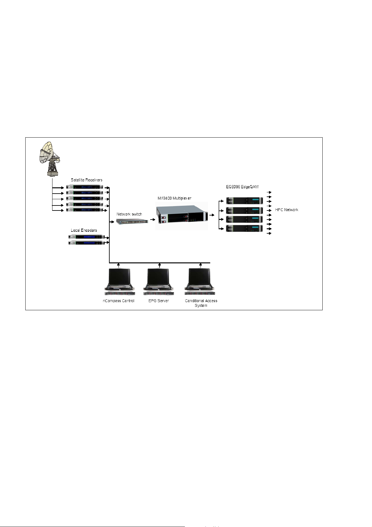
1.4 Role of the MX8400 Multiplexer .........................................................1-12
1.4.1 The MX8400 Multiplexer as an iSIS 8000 Solution Component......... 1-12
1.4.2 MX8400 Multiplexer Control Using nCompass................................... 1-12
1.5 Guided Tour........................................................................................ 1-12
1.5.1 Construction .......................................................................................1-12
1.5.2 Indicators ............................................................................................1-13
1.5.2.1 Front Panel Indicators ........................................................................ 1-13
1.5.2.2 Rear Panel Connectors ......................................................................1-13
2/1553-FGC 101 1014 Uen B
1-1
Page 10

Introduction
1.5.2.3 Rear Panel Indicators......................................................................... 1-14
List of Figures
Figure 1.1 Front View of the MX8400 Multiplexer [Dual PSU]............................... 1-4
Figure 1.2 Current Label (Affixed to the side of the unit) ....................................... 1-5
Figure 1.3 Current Label (Affixed to the rear of the unit) ....................................... 1-5
Figure 1.4 The Role of the MX8400 Multiplexer in a Cable Distribution System . 1-12
Figure 1.5 Front Panel Indicators ........................................................................ 1-13
Figure 1.6 Typical Rear View of the MX8400 Multiplexer.................................... 1-13
Figure 1.7 Rear Panel Indicators ......................................................................... 1-14
List of Tables
Table 1.1 Model Number Descriptions .................................................................. 1-4
Table 1.2 Software License Key Descriptions ....................................................... 1-4
Table 1.3 Static Parameters [Reflex] ................................................................... 1-10
1-2
2/1553-FGC 101 1014 Uen B
Page 11

Introduction
1.1 Terminology
In this Reference Guide, the following definitions apply:
• MX8400 or MX8400 Multiplexer refers to the product MX8400 MPEG
Video/Audio/Data Multiplexer;
• Multiplexer refers to a single multiplexing engine within the MX8400 which
provides a single multi-program transport stream (MPTS) output.
1.2 Scope of this Guide
1.2.1 Who Should Use this Guide
This guide is written for operators and users of the MX8400 MPEG
Video/Audio/Data Multiplexer and describes its functions and operation. It will assist
in the installation and day-to-day care and operation of the unit. Maintenance
information that requires covers to be removed is not included.
Do not remove the covers of this equipment. Hazardous voltages are present within
this equipment and may be exposed if the covers are removed. Only suitably trained
and experienced service engineers are permitted to service this equipment.
Unauthorized maintenance or the use of non-approved replacements may affect the
equipment specification and invalidate any warranties.
1.2.2 What this Guide Describes
1.2.2.1 Identifying the Equipment
Figure 1.1 shows the front of the MX8400 MPEG Video/Audio/Data Multiplexer.
There are no controls or connectors at the front panel. However, the PSU (dual if
two are fitted) are accessed from the front panel.
Warning!
Caution!
2/1553-FGC 101 1014 Uen B
1-3
Page 12

Introduction
Figure 1.1 Front View of the MX8400 Multiplexer [Dual PSU]
1.2.2.2 Product Codes
This guide covers products with the marketing codes shown below. See Table 1.1
for a full explanation of the marketing codes, labeling and descriptions.
Table 1.1 Model Number Descriptions
Model Number
Marketing Code
Description
Summary of Features
Price Object Number
The functionality of the Multiplexer can be augmented by purchasing software
licensing keys. These are described in Table 1.2.
Table 1.2 Software License Key Descriptions
Marketing Code:
MUX DVBCA DVBCA/EXT SFN
MX8400/SWO/…
Option
Description
Additional
Multiplexed Output
Enables each
additional MPTS
output.
DVB CA Base
Option
Enables DVB
Common
Scrambling
Algorithm for one
transport stream.
E10246
MX8400/BAS/DPS
2U base Unit with S13512 master card
See Section 1.3
FAZ 101 0114/31
Additional DVB CA
System Support
Enables DVB
Common
Scrambling
Algorithm for each
additional
multiplexed output
transport stream
Additional SFN
Capable TS Output
Enables additional
SFN capable TS
outputs
Price Object
Number
Supply Object
Number
1-4
2/1553-FGC 101 1014 Uen B
FAZ 101 0114/8 FAZ 101 0114/6 FAZ 101 0114/7 FAZ 101 0114/10
FAT 102 0184 FAT 102 0185 FAT 102 0186 FAT 102 0189
Note: See Chapter 3, Hardware Options, and Software Licenses for information
relating to other purchasable options and licenses.
Page 13

Introduction
1.2.3 Equipment Information Label
1.2.3.1 Contents of Label
On the side and rear of the unit there are information labels Figures 1.2 & Figure 1.3
Which Identifies the configuration of the unit. The inclusion of options may affect the
rear panel labeling
Equipment
Number and
Product Type
Bar Code
Used for unit
identification
in the
manufacturing
process
8000 MULTIPLEXER
Serial No.TB46323
IIIIIIIIIIIIIIIIIIIIIIIIIIIIIIIIIIIIIIIIIIIIIIIIIIIIII
MX8400/BAS
Figure 1.2 Current Label (Affixed to the side of the unit)
8000
MULTIPLEXER
S/N TB46323
KDU XXX XXX/X
Figure 1.3 Current Label (Affixed to the rear of the unit)
Serial Number
A unique number
for unit
Product Number
A code which
identifies the
product for
1.2.3.2 Firmware/Software Versions
This guide has been written to cover the functionality of the firmware/software
versions which are contained within the Release Version 5.2.0
1
.
This guide continues to be relevant to subsequent build versions where the
functionality of the equipment has not changed. Where the build standard changes
the functionality, a new issue of this guide will be provided.
1
Release Version 3.0 and later guarantees option card functionality. Versions earlier than 2.0.0 do not support all option cards.
2/1553-FGC 101 1014 Uen B
1-5
Page 14

Introduction
1.3 Summary of Features
1.3.1 Overview
The MX8400 MPEG Video/Audio/Data Multiplexer is housed in a 2RU, 19-inch rack
mounted unit. It is designed to meet the needs of IP distribution infrastructures. It is
ideally suited to a wide range of multiplexing and re-multiplexing applications. These
include primary multiplexing in headends for Direct-to-Home (DTH) satellite
contribution and distribution systems. It can also provide the hub for applications in
cable and terrestrial television central headends.
1.3.2 Main Features
• Up to eight independent output transport streams, each capable of creating a
multi-program stream conforming to the MPEG-2 transport layer specification
(ISO/IEC 13818-1 MPEG-2 Systems). Each multiplexer can be configured
independently e.g. output data rates, PCR mode of operation.
Note: The MX8400/BAS provides a single multiplexer engine which produces a
single output transport stream, additional multiplexers are a licensable
feature (MX8400/SWO/MUX).
• The maximum output bit rate for a single multiplexer is 250 Mbps. The
resolution, to which the output rate of a transport stream can be set, by entering
a bit rate, is 1 bps.
• The output bit rate can be set exactly to any of the DVB-T modes.
• SFN adapter functionality is included to produce an output transport stream in
accordance to TS 101 191 V1.4.1.
Note: When operating in SFN mode, the output bit rate is calculated as described
in Annex H.
• The maximum aggregated output bit rate is 1 Gbps, shared across the transport
streams created.
• Each multiplexer supports Ericsson Reflex Statistical Multiplexing (see also
Section 1.3.3 for Remote Reflex). This enables connected Encoders to be
grouped together to share an overall group bit rate, allocating a percentage of
the total bit rate to each Encoder depending on the complexity of the encoded
content.
1-6
• Ericsson Reflex Statistical Multiplexing allows bandwidth harvesting to help
maintain quality targets. Any bit rates not being used by multiplexed components
are distributed across all component video services. Data rate sharing between
components allows a user-defined higher quality-target component to take
bandwidth from user-defined lower quality-target components.
• Internal time references are used to ensure the multiplexing process does not
affect time critical data.
2/1553-FGC 101 1014 Uen B
Page 15

Introduction
• Multiplexer output transport streams can be created from any services or
components carried on any input transport stream. A single component can also
be used in multiple output transport streams. Each multiplexer engine receives
PSI/SI/PSIP table data via nCompass Control and manages the carousel
insertion of that data into the associated transport stream output.
• A maximum of 8192 PIDs for each multiplexer is supported.
• The dynamic PID tracking of incoming services is supported.
• PID filtering is supported to allow the removal of unwanted PIDs.
• PID remapping is supported to allow a component received on one PID to be
output on a different PID.
• Missing incoming PIDs can be detected and used to initiate appropriate alarms
to nCompass Control. Detected PIDs can also be excluded from the monitoring.
• The MX8400 can operate in both active and redundant modes. Synchronization
of MX8400 configurations is automatically maintained for redundant mode of
operation.
• The MX8400 provides Program Level Redundancy by sourcing any transport
streams missing from the primary network from the secondary network without
affecting any other active service. Refer to Annex E, Redundancy Modes for
further details.
• The MX8400 supports dual redundant 10/100 Ethernet interfaces for system
control and for CA data.
• The MX8400 supports a single fixed power supply(100-240 V AC)
• The MX8400 supports an Alarm relay connection.
1.3.2.1 Program Specific Information Generator (PSIG)
PSIG (described by ETSI TS 103 197, DVB: High-end Implementation of DVB
Simulcrypt) is supported by this release of the MX8400.
The PSI Generator (PSIG) is defined as the head-end process(es) responsible for
generating MPEG-2 PSI (Program Specific Information) tables.
Note: Please refer to Annex I PSIG Support for further information.
1.3.2.2 Program Clock Reference (PCR)
• Multiplexing non-time stamped components (e.g. DVB Subtitles or MHEG Data)
between incoming services is supported.
• The MX8400 supports mixing time stamped components that reference valid
PCR PIDs from different remultiplexed feeds/incoming services. This is normally
only supported with feeds that use a single PCR reference in the incoming
transport stream or single PCR based Encoder's inputs.
2/1553-FGC 101 1014 Uen B
1-7
Page 16

Introduction
• Each multiplexer supports the use of re-multiplexed PCRs (that is all multiplexed
services maintain their original program clock reference) or a single common
PCR (all incoming services are time adjusted to reference an internally
generated PCR).
Note: When operating in single PCR mode all contributing services must be
locked to a single common clock reference e.g. studio clock (HSYNC IN).
• Release 5 of the MX8400 provides the capability, under nCC control, to allow
the remultiplexing of transport streams without reading, analyzing or processing
the PCR. This means the user can specify that an incoming transport stream
uses a raw bit rate measurement (i.e. ignore the PCR values in the transport
stream).
1.3.2.3 Frequency Synchronization
• The main MX8400 system reference clock is an internal 27 MHz voltage
controlled oscillator. It can be locked to an externally sourced clock reference,
via the HYSNC input or GPS input. It can, also, be locked to the high-precision
on-board clock if no external source is available.
• Dual HSYNC clock inputs support the option of locking an internal frequency
reference to an external studio clock. The external clock reference is
configurable to accept 625 or 525 line video standards.
• Dual HYSNC clock output.
1.3.2.4 Table Generation
• The MX8400 can generate and insert the DVB Time and Date Table.
• The MX8400 can insert the DVB Time Offset Table. (This requires the use of
third-party equipment.)
• The MX8400 can insert the PSIP System Time Table. (This will require the use
of third-party equipment.)
1.3.2.5 TS IP Summary of Features
• Four independent
2
GbE transport stream data ports are provided. Each port
supports both RTP and UDP formatted packets.
• GbE interfaces support IP packet jitter removal
1.3.2.6 ASI Input/Output Summary of Features
• Four ASI outputs are provided. These support 188 and 204 byte transport
stream packets and are able to operate in byte and single packet burst mode.
• Two ASI inputs are provided. These support 188 and 204 byte transport stream
packets and are able to operate in byte and single packet burst mode.
2
Each port has its own MAC address.
1-8
2/1553-FGC 101 1014 Uen B
Page 17

Introduction
• Indicators at the rear panel of the unit indicate the status of the ASI input and
outputs. These are described in Section 2.7.5 of Chapter 2, Installing and
Powering Up.
1.3.2.7 Dual PSU
The MX8400 Multiplexer is now available with dual hot-swap PSUs. See Chapter 5
for more information relating to the PSU.
Note: This is a new product and not an upgrade path.
1.3.3 Remote Reflex
1.3.3.1 Statistical Multiplexing
Statistical multiplexing delivers the efficient use of bandwidth whilst maintaining
picture quality. It makes use of the variable bit rate nature of video compression and
the improbability that all channels will peak in bit- rate demand simultaneously.
Grouping encoders together and allowing the group to share an aggregate pool of
bit rate enables the head-end system to provide either a better picture quality than
constant bit rate operation, or to maintain constant quality while adding more
channels into the multiplex.
Reflex is Ericsson's implementation of statistical multiplexing and is associated with
a multiplexer being co-sited with the encoder-sourced services. Remote Reflex is
used when services are sourced from encoders which are sited remotely from the
multiplexer.
1.3.3.2 Remote Statistical Multiplexing
With the introduction of IP-based connectivity between the MX8400 multiplexer and
the new encoder ranges, the Reflex technology has been extended to support
encoders located at remote locations over Wide Area Network to offer additional
benefits of further improved picture quality, higher efficiency and reduced capital
expenditure.
Up to 64 services for each output transport stream can be supported using Remote
Reflex. However, the total number of outgoing services across all transport streams
is limited to 400.
Remote Statistical Multiplexing is only available over IP and is not available for ASI
connections.
1.3.3.3 Reflex Operation
Remote Reflex allows statistical multiplexing of encoders located at a distance from
the MX8400, providing that the largest network latency between an encoder and the
MX8400 is no greater than 400 milliseconds.
2/1553-FGC 101 1014 Uen B
1-9
Page 18

Introduction
A system dependant delay constant is defined at the system configuration stage.
The MX8400 calculates the latency for individual Encoders and sets buffers
appropriately to ensure all Encoders within the system experience the same network
delay. This is achieved by ensuring the delay an Encoder service experiences is
equal to the predefined system delay constant.
An Encoder at a remote site will experience a larger delay in the network and is
therefore delayed less within the MX8400 input than an local based Encoder service
which is part of that the same Remote Reflex group.
1.3.3.4 Reflex Static Parameters
Table 1.3 lists all the static parameters associated with the Reflex function.
Table 1.3 Static Parameters [Reflex]
Name
Status Update
Period
V1 Reflex Update
Rate
Encoder Wait Time
Reflex Delay
V4 Reflex Update
Rate
V4 Reflex Mux
Lookahead
PCR exchange
interval
Description Value
(25Hz
encoder
system)
Interval between V4 Reflex status reports from
encoder.
The rate(times/sec) at which set bit rate
messages are sent to V1 Reflex encoders.
For V1 reflex, the timeout period for all poll
responses from the encoders to be received by
the mux.
Delay in activating a reflex input, after
configuration.
The rate(times/sec) at which set bit rate
messages are sent to V4 Reflex encoders.
The mux lookahead period used to calculate apply
time in V4 Reflex set bit rate messages.
Interval between mux sending PCR Exchange
messages to V4 Reflex encoders.
400 ms 133 ms
25 s 30 s
25 ms 18 ms
3 s 3 s
25 s 30
400 ms 330 ms
1000 ms
Value
(29.97Hz
encoder
system)
1000 ms
Bit rate On Failure
Delay ms
Reflex broadcast V1 Reflex broadcast messaging - on/off off off
Delay period before assuming configured bit rate
on failure value for failing V4 Reflex encoder
2500 ms 2500 ms
Note: In Table 1.3, V1 Reflex refers to Reflex and V4 Reflex refers to Remote
Reflex.
1-10
2/1553-FGC 101 1014 Uen B
Page 19

Introduction
1.3.4 Conditional Access
1.3.4.1 DVB CA (Option)
• DVB CA, compliant with ETSI TS 103 197 V1.4.1, is supported via two RJ-45
GbE Ethernet connectors.
• CA is supported on all eight output transport streams.
1.3.4.2 BISS
• BISS
3
Modes 0 and 1 are supported as standard on this release. The
scrambling mechanism, as defined in the DVB-CSA specification, is applied at
the Transport level only. This is configured using nCompass Control.
- Mode 0: No scrambling.
- Mode 1: All components are scrambled by a fixed Control Word (CW),
derived from a clear Session Word (SW). The MX8400 accepts the session
word is via an XML control interface. Any invalid session words will be
rejected (it must be a 12 character hex string).
• Individual transport streams can be scrambled simultaneously with either
DVB CA or BISS but not individual components. The MX8400 will only support
one scrambling method on a single PID.
1.3.5 Single Frequency Networks Functionality
The MX8400 Multiplexer supports up to eight output transport streams with SFN
data. The SFN data for each output transport stream can be configured
independently via nCompass Control.
Note: Please refer to Annex H Setting up the SFN Functionality for further
information.
1.3.6 Extended Functionality
Multiplexer functionality can be extended by the use of purchasable options. See
Chapter 3, Hardware Options and Software Licenses for information.
3
Basic Interoperable Scrambling System: Non-proprietary encryption from EBU (Tech3290).
2/1553-FGC 101 1014 Uen B
1-11
Page 20
Introduction
1.4 Role of the MX8400 Multiplexer
1.4.1 The MX8400 Multiplexer as an iSIS 8000 Solution Component
The MX8400 Multiplexer is a component of Ericsson iSIS 8000 solution and is
designed for use by broadcasters and distributors of video, audio and data services.
F igure 1.4 shows the MX8400 Multiplexer’s role in a cable distribution scheme.
Figure 1.4 The Role of the MX8400 Multiplexer in a Cable Distribution System
1.4.2 MX8400 Multiplexer Control Using nCompass
The MX8400 Multiplexer is designed for unattended operation. Operation is through
the Ericsson’s nCompass GUI.
1.5 Guided Tour
1.5.1 Construction
The MX8400 Multiplexer is a modular construction comprising a main board and a
fixed PSU. It is constructed using a screened self-ventilated housing with all inputs
and outputs via rear panel connectors.
1-12
2/1553-FGC 101 1014 Uen B
Page 21
Introduction
]
The unit is designed for mounting in a 19-inch rack. The equipment operates from a
forced air-cooled power supply unit contained within the Multiplexer.
1.5.2 Indicators
1.5.2.1 Front Panel Indicators
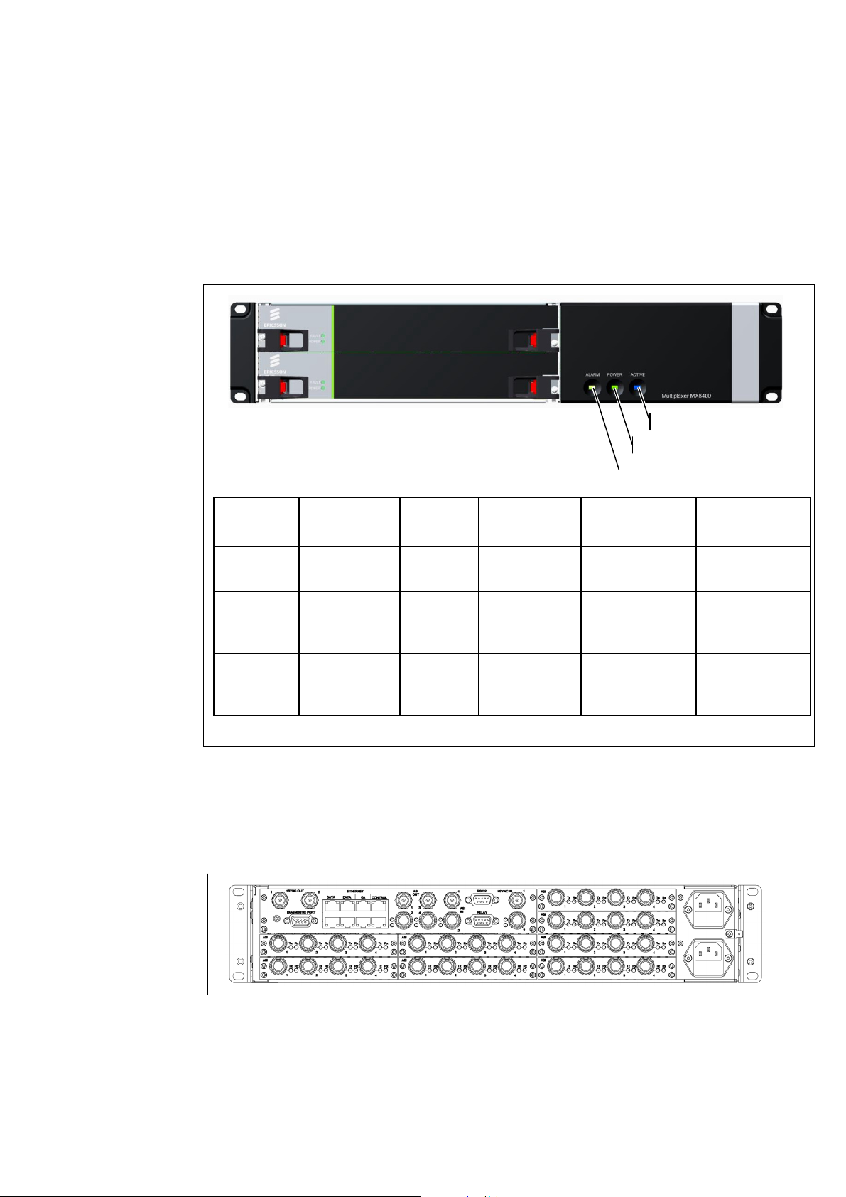
There are three indicators on the front panel as shown in Figure 1.5.
Blue Indicator [Active]
Green Indicator [Power
Red Indicator [Alarm when lit]
Position Indicates Colour Condition Function
Left Alarm Red On
Middle Power Green On
Right Active Blue
Figure 1.5 Front Panel Indicators
1.5.2.2 Rear Panel Connectors
All input and output connectors are located at the rear of the equipment
(see Figure 1.6 Typical Rear View of the MX8400 Multiplexer).
Off
On
When Lit
Multiplexer
general alarm
Power is
applied to the
unit
Redundant
Active
Comment
Used in
redundancy
systems
Figure 1.6 Typical Rear View of the MX8400 Multiplexer
2/1553-FGC 101 1014 Uen B
1-13
Page 22
Introduction
For pin-out information, see Chapter 2, Installing and Powering Up. For
specifications of the connector interfaces, see Annex B, Technical Specification.
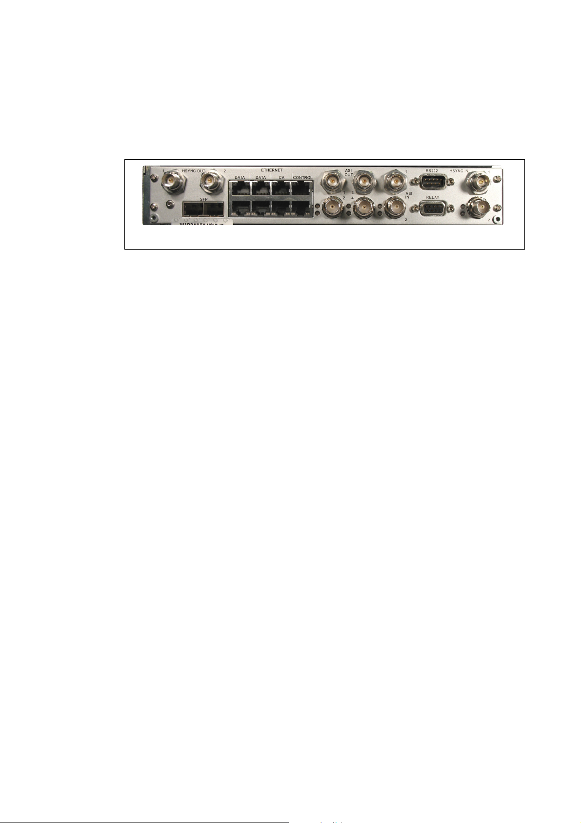
1.5.2.3 Rear Panel Indicators
Figure 1.7 shows the position of the rear panel indicators on the Multiplexer Card.
Figure 1.7 Rear Panel Indicators
Indicators associated with the Ethernet interface, RJ-45 connectors provide a visual
indication of link, activity and speed. See Chapter 2 for an explanation.
Other indicators are associated with the ASI inputs/outputs and the status of the
dual HSYNC IN connectors.
1-14
2/1553-FGC 101 1014 Uen B
Page 23

2 Installing and Powering Up
Chapter 2
Contents
2.1 Introduction........................................................................................... 2-5
2.1.1 General................................................................................................. 2-5
2.1.2 Site Requirements ................................................................................2-5
2.1.2.1 Power Supplies.....................................................................................2-5
2.1.2.2 Environment ......................................................................................... 2-5
2.1.2.3 Lightning Protection.............................................................................. 2-5
2.2 Preliminary Checks............................................................................... 2-6
2.2.1 Mechanical Inspection ..........................................................................2-6
2.2.2 Moving the Equipment Safely............................................................... 2-6
2.3 Installing the Equipment ....................................................................... 2-6
2.3.1 Handling ...............................................................................................2-6
2.3.2 Installing the Equipment ....................................................................... 2-6
2.3.3 Lifting ....................................................................................................2-7
2.3.4 Fixing ....................................................................................................2-7
2.3.5 Cable Routing....................................................................................... 2-7
2.3.6 Equipment Access................................................................................ 2-7
2.3.7 Ventilation............................................................................................. 2-8
2.3.7.1 Airflow................................................................................................... 2-8
2.3.7.2 Temperature Monitoring .......................................................................2-9
2.4 EMC Compliance Statements ..............................................................2-9
2.4.1 EN 55022/AS/NZS 3548....................................................................... 2-9
2.4.2 FCC ...................................................................................................... 2-9
2.5 Connecting up the MX8400 Multiplexer.............................................. 2-10
2.6 AC Supply Operating Voltage, Fusing and Earthing ..........................2-10
2.6.1 AC Supply........................................................................................... 2-10
2.6.2 AC Equipment Fuse ...........................................................................2-11
2.6.3 Power Cable and Earthing.................................................................. 2-11
2.6.3.1 General............................................................................................... 2-11
2.6.3.2 Disposal of Moulded Plugs................................................................. 2-11
2.6.3.3 AC Supply Cord.................................................................................. 2-12
2.6.4 Protective Earth/Technical Earth ........................................................2-12
2.6.4.1 General............................................................................................... 2-12
2.6.4.2 Technical Earth................................................................................... 2-13
2.6.5 Connecting the Equipment to the AC Supply ..................................... 2-13
2.7 Signal Connections............................................................................. 2-14
2.7.1 Scope of This Section......................................................................... 2-14
2.7.2 Connecting Cables ............................................................................. 2-14
2/1553-FGC 101 1014 Uen B
2-1
Page 24

Installing and Powering Up
2.7.3 MX8400 Multiplexer Rear Panel......................................................... 2-14
2.7.4 MX8400 Multiplexer Connectors ........................................................ 2-16
2.8 Ethernet Data 1 – 4 Ports................................................................... 2-17
2.8.1 Overview ............................................................................................ 2-17
2.8.1.1 Port Configurations............................................................................. 2-17
2.8.1.2 Activity and Speed Indications ........................................................... 2-18
2.8.1.3 Input Mode ......................................................................................... 2-18
2.8.1.4 Output Mode ...................................................................................... 2-19
2.8.2 Static Parameters............................................................................... 2-19
2.8.2.1 Data Ports .......................................................................................... 2-19
2.8.2.2 Data Port IO Mode ............................................................................. 2-20
2.8.3 Reported Faults.................................................................................. 2-21
2.9 ASI IN 1 and 2.................................................................................... 2-22
2.9.1 Overview ............................................................................................ 2-22
2.9.1.1 Functional Description........................................................................ 2-22
2.9.1.2 Connectors......................................................................................... 2-22
2.9.2 Alarm Indications................................................................................ 2-22
2.10 ASI OUT 1 to 4................................................................................... 2-23
2.10.1 Overview ............................................................................................ 2-23
2.10.1.1 Functional Description........................................................................ 2-23
2.10.1.2 Connectors ......................................................................................... 2-23
2.10.2 Alarm Indications................................................................................ 2-23
2.11 Ethernet CA 1 and 2........................................................................... 2-24
2.11.1 Overview ............................................................................................ 2-24
2.11.1.1 Functional Description........................................................................ 2-24
2.11.1.2 Indicators............................................................................................ 2-24
2.11.2 Static Parameters............................................................................... 2-25
2.11.2.1 Overview ............................................................................................ 2-25
2.11.2.2 ECMGs Table..................................................................................... 2-26
2.11.2.3 Reported Faults.................................................................................. 2-26
2.12 Ethernet Control 1 & 2........................................................................ 2-27
2.12.1 Overview ............................................................................................ 2-27
2.12.1.1 Functional Description........................................................................ 2-27
2.12.1.2 Indicators............................................................................................ 2-27
2.12.2 Static Parameters............................................................................... 2-28
2.12.3 Reported Faults.................................................................................. 2-28
2.13 RELAY Connector.............................................................................. 2-29
2.14 RS-232 Engineering Port ................................................................... 2-29
2.15 HSYNC Clock Reference ................................................................... 2-30
2.15.1 Overview ............................................................................................ 2-30
2.15.1.1 HSYNC IN (2 off)................................................................................ 2-30
2.15.1.2 HSYNC OUT (2 off)............................................................................ 2-30
2.15.2 Static Parameters............................................................................... 2-31
2.15.3 Reported Faults.................................................................................. 2-31
2.16 Upgrading the MX8400 Multiplexer.................................................... 2-32
2.17 Powering Up/Down ............................................................................ 2-32
2.17.1 Before Powering Up ........................................................................... 2-32
2.17.2 Powering Up....................................................................................... 2-32
2.17.3 Power up Self Test ............................................................................. 2-33
2.17.4 Start up Sequence.............................................................................. 2-33
2.17.5 MX8400 Multiplexer Configurations ................................................... 2-33
2.17.6 Using nCompass Control ................................................................... 2-33
2-2
2/1553-FGC 101 1014 Uen B
Page 25

Installing and Powering Up
2.17.7 Powering Down .................................................................................. 2-34
List of Figures
Figure 2.1 Airflow Through the MX8400 Multiplexer ..............................................2-8
Figure 2.2 AC Supply Inlet Assembly................................................................... 2-11
Figure 2.3 Location of the Technical Earth (Unit Rear)........................................ 2-13
Figure 2.4 MX8400 Rear Panel Connectors ........................................................ 2-14
Figure 2.5 MX8400 Multiplexer Connections ....................................................... 2-15
Figure 2.6 Signal Connectors on the MX8400 Multiplexer Rear Panel................ 2-16
Figure 2.7 Static Parameters - Editing Data Ports ............................................... 2-19
Figure 2.8 Static Parameters - Data IO Port Mode .............................................. 2-20
Figure 2.9 Editing ECMGs ...................................................................................2-26
Figure 2.10 MX8400 Start up Routine.................................................................. 2-32
List of Tables
Table 2.1 AC Supply Cable Wiring Colours ......................................................... 2-12
Table 2.2 Signal Connectors on the MX8400 Multiplexer Rear Panel .................2-16
Table 2.3 MX8400 IP/GbE Interface Port Configurations ....................................2-17
Table 2.4 Ethernet Data 1 - 4 Interface Indicators ............................................... 2-18
Table 2.5 Input Mode Configurations...................................................................2-18
Table 2.6 Output Mode Configurations ................................................................ 2-19
Table 2.7 Static Parameters - Data Port Table .................................................... 2-20
Table 2.8 Static Parameters - Editing Data Port IO Mode ...................................2-21
Table 2.9 Ethernet Input Reported Faults............................................................2-21
Table 2.10 Ethernet Input Reported Faults..........................................................2-22
Table 2.11 ASI Input - Transport Stream Input (2 off)......................................... 2-22
Table 2.12 ASI IN Interface Indicators ................................................................. 2-23
Table 2.13 ASI Transport Stream Output (4 off) .................................................. 2-23
Table 2.14 ASI OUT Interface Indicators ............................................................. 2-24
Table 2.15 Ethernet CA 1 and 2 Connectors ....................................................... 2-24
Table 2.16 Ethernet CA 1 and 2 Interface Indicators...........................................2-25
Table 2.17 Static Parameters [CA]....................................................................... 2-25
Table 2.18 Ethernet CA 1 and 2 Reported Faults................................................2-26
Table 2.19 Ethernet Control 1 and 2 Connectors................................................. 2-27
Table 2.20 Ethernet Control 1 and 2 Interface Indicators ....................................2-27
Table 2.21 Static Parameters [Control]................................................................2-28
Table 2.22 RELAY Connector.............................................................................. 2-29
Table 2.23 RS-232 Engineering Port ................................................................... 2-29
Table 2.24 HSYNC IN..........................................................................................2-30
Table 2.25 HSYNC IN Interface Indicators ..........................................................2-30
Table 2.26 HSYNC Output................................................................................... 2-31
Table 2.27 Static Parameters (HSYNC)............................................................... 2-31
2/1553-FGC 101 1014 Uen B
2-3
Page 26

Installing and Powering Up
BLANK
2-4
2/1553-FGC 101 1014 Uen B
Page 27

Installing and Powering Up
2.1 Introduction
2.1.1 General
This chapter provides configuration and connection information for planning the
installation of the MX8400 Multiplexer, or for installing the equipment at another
location. This information also enables the final set up of the equipment to be
checked in the event of a fault. In the event of problems, contact Ericsson Customer
Services (see Preliminary Pages).
2.1.2 Site Requirements
2.1.2.1 Power Supplies
The MX8400 Multiplexer can operate from the following power supply voltage range:
• 100 – 240 V AC, 50/60 Hz (80 W with NO options fitted).
See Annex B, Technical Specification for a full specification.
2.1.2.2 Environment
The MX8400 Multiplexer is intended to operate in ambient air temperature
conditions in the range 0°C to +50°C, and humidity 0% to 95% (non-condensing).
See Annex B, Technical Specification for a full specification. Do not install this
product in areas of high humidity or where there is danger of water entry.
2.1.2.3 Lightning Protection
If the MX8400 Multiplexer has been subject to a lightning strike or power surge and
has stopped working, disconnect the power supply immediately. Do not reconnect
power until it has been checked for safety. if in doubt, contact Ericsson customer
services.
Where appropriate, ensure this product has an adequate level of lightning
protection. Alternatively, during a lightning storm or when it is left unattended and
unused for long periods of time, unplug it from the supply outlet and disconnect the
antenna or cable system. This will prevent damage to the product from lightning and
power line surges.
Warning!
2/1553-FGC 101 1014 Uen B
2-5
Page 28

Installing and Powering Up
2.2 Preliminary Checks
2.2.1 Mechanical Inspection
When taking delivery of an MX8400 Multiplexer, check the equipment items
delivered against the enclosed delivery note. Inspect the equipment for damage in
transit. If in doubt, contact Ericsson Customer Services (see Preliminary Pages).
Warning!
Do not remove the covers of this equipment. doing so may invalidate warranties,
cause a safety hazard or affect performance or both. Please check with Ericsson
Customer Services beforehand.
2.2.2 Moving the Equipment Safely
Do not place the MX8400 Multiplexer on an unstable cart,
stand, bracket, or table. The equipment may fall, causing
serious injury and serious damage to the equipment. Use only
with a cart, stand, bracket or table recommended by Ericsson.
An appliance and cart combination should be moved with care. Quick stops,
excessive force, and uneven surfaces may cause the appliance and cart
combination to overturn.
Do not move or carry the equipment whilst it is still connected to the supply or
other leads, is live, or is in operation.
2.3 Installing the Equipment
2.3.1 Handling
The MX8400 Multiplexer must be handled carefully and thoughtfully to prevent
safety hazards and damage.
2.3.2 Installing the Equipment
Ensure all personnel designated to fit the unit have the appropriate skills and
knowledge. If in any doubt, contact Ericsson Customer Services (see Preliminary
Pages for contact details).
2-6
2/1553-FGC 101 1014 Uen B
Page 29

Installing and Powering Up
Installation should be in accordance with the following instructions and should only
use installation accessories recommended by the manufacturer. When rack
mounted, this equipment must have shelf supports as well as being fixed at the front
panel.
2.3.3 Lifting
The MX8400 Multiplexer may be awkward to lift. Do not attempt to lift or move it
without proper assistance or equipment. If in doubt, seek assistance.
2.3.4 Fixing
• The MX8400 Multiplexer can be installed in a 19-inch rack.
• Slide the product onto the chassis supports and affix to the rack by means of an
M6 x 18 mm panhead screw in each corner.
• Ensure that the equipment is firmly and safely located and has an adequate
through-flow of air.
• The equipment must be installed and operated in the normal horizontal
orientation, i.e. not inverted or standing on one side.
• The MX8400 must be stationary during operation.
• The MX8400 must not be used as a support for any other equipment.
2.3.5 Cable Routing
Power supply cables should be routed so that they are not likely to be walked on or
pinched by items placed upon or against them. Pay particular attention to cables at
plugs, convenience receptacles, and the point where they exit from the appliance.
Do not run AC power cables in the same duct as signal leads.
2.3.6 Equipment Access
Ensure that the MX8400 Multiplexer is installed to allow access to the rear of the
equipment and access to the connectors.
2/1553-FGC 101 1014 Uen B
2-7
Page 30

Installing and Powering Up
g
2.3.7 Ventilation
2.3.7.1 Airflow
Warnings!
Never push objects of any kind into the openings of the equipment as they may
touch dangerous voltage points or short out parts that can cause a fire or electric
shock.
Prevent spillage of any liquid on the product.
Cautions!
Openings in the cabinet are provided for ventilation and to ensure reliable operation
of the product and protection from overheating. These openings must not be
blocked or covered.
This product should never be placed near or over a radiator or other source of heat.
This product should not be placed in a built-in installation such as a rack unless
proper ventilation is provided or the instructions have been adhered to.
Do not install equipment so that the air intake of one aligns with the outlet on
another. Provide baffles and adequate spacing.
The fans contained within this unit are not fitted with dust and insect filters. Pay
particular attention to the environment in which the unit is to be used.
When the MX8400 is placed in a built-in installation such as a rack, proper
ventilation must be provided and all installation instructions followed. Allow at least
50mm (two inches) of free-air space at each side of the equipment to ensure
adequate cooling.
Warmed air is
exhausted
Cool air is drawn
in from the left.
from the ri
ht.
2-8
Figure 2.1 Airflow Through the MX8400 Multiplexer
Units in racks can be stacked without the need for ventilation panels between them.
Racks containing stacked equipment may need to be forced air-cooled to reduce the
ambient temperature within the rack.
2/1553-FGC 101 1014 Uen B
Page 31

Installing and Powering Up
2.3.7.2 Temperature Monitoring
Unit Temperature Monitoring
The equipment has an over-temperature (>50°C) alarm which is used to drive the
fail indication (see below).
Power Supply Unit Temperature Monitoring
A temperature warning circuitry monitors the PSU case temperature. The monitor
circuit output signal changes from high to low impedance, when the case
temperature exceeds the upper threshold level, and changes back to high
impedance, when case temperature falls below the lower threshold level, which is
85 °C ± 5 °C.
If the PSU case exceeds 105 °C, the PSU shuts down. It will resume operation
automatically, once the case temperature falls below 105 °C.
Fail Indication
The alarm illuminates the front panel FAIL indicator and drives a Fail relay which is
accessed via a rear panel connector.
When the equipment is installed in a redundancy configuration, the alarm can be
used by nCompass Control to trigger a change-over to a standby MX8400
Multiplexer. The relay is non-latching and will revert to its normal state when the fail
condition is corrected.
2.4 EMC Compliance Statements
2.4.1 EN 55022/AS/NZS 3548
The MX8400 Multiplexer is a Class A product. In a domestic environment this
product may cause radio interference so it may be necessary for the user to take
adequate measures.
2.4.2 FCC
This equipment has been tested and found to comply with the limits for a Class A
digital device, pursuant to Part 15 of the FCC Rules. These limits are designed to
provide reasonable protection against harmful interference when the equipment is
operated in a commercial environment.
This equipment generates, uses, and can radiate radio frequency energy and, if not
installed and used in accordance with the Reference Guide, may cause harmful
interference to radio communications. Operation of this equipment in a residential
area is likely to cause harmful interference in which case the user will be required to
correct the interference at their own expense.
2/1553-FGC 101 1014 Uen B
2-9
Page 32

Installing and Powering Up
2.5 Connecting up the MX8400 Multiplexer
Warning!
Do not move or install equipment when still attached to the AC supply.
Caution!
Ensure ESD precautions are observed when inter-connecting equipments.
When the equipment has been installed in its intended operating position it is ready
to be connected to the rest of the system equipment. There are two sets of
connections to be made: internal and external.
All connections to external equipment are described in more detail in the following
paragraphs. Pin-out details for these connections start at Section 2.7.
2.6 AC Supply Operating Voltage, Fusing and Earthing
2.6.1 AC Supply
Warning!
Do not overload wall outlets and extension cords as this can result in a risk of fire or
electric shock.
Caution!
This product should be operated only from the type of power source indicated on the
marking label. If you are not sure of the type of power supply to your business,
consult a qualified electrical engineer or your local power company.
The equipment operates from a wide-ranging AC supply input, accepting voltages in
the range 100 – 240 V AC at 50/60 Hz nominal. Refer to Annex B, Technical
Specification for a full power supply specification.
2-10
There are no links or switches that need to be altered when operation is made from
different AC supplies. The full Technical Specification is given in Annex B at the
back of this guide.
2/1553-FGC 101 1014 Uen B
Page 33

Installing and Powering Up
2.6.2 AC Equipment Fuse
In addition to the fuse in the supply cable plug (if appropriate) there is a power
supply fuse located in an integral fuse carrier at the AC supply inlet at the back of
the equipment (see Figure 2.2).
Fuse Carrier
Figure 2.2 AC Supply Inlet Assembly
Note: See Chapter 5, Preventive Maintenance and Fault-finding for the fuse
replacement procedure.
2.6.3 Power Cable and Earthing
2.6.3.1 General
Check that the AC supply cable is suitable for the country in which the equipment is
to be used.
2.6.3.2 Disposal of Moulded Plugs
When the moulded plug fitted to the AC supply cable supplied with this equipment is
not required, please dispose of it safely. Failure to do so may endanger life as live
ends may be exposed if the removed plug is inserted into an AC supply outlet.
Warning!
2/1553-FGC 101 1014 Uen B
2-11
Page 34

Installing and Powering Up
2.6.3.3 AC Supply Cord
Warning!
Do not route AC supply cords where they likely to be walked on or pinched by items
placed upon or against them. Pay particular attention to cords at plugs, convenience
receptacles, and the point where they exit the appliance.
The equipment is supplied with a two metre detachable AC supply cable fitted with a
moulded plug suitable for either the USA, UK or Europe.
The wires in the AC supply cable are coloured in accordance with the wire colour
code shown in Table 2.1.
Table 2.1 AC Supply Cable Wiring Colours
UK
(BS 1363)
Earth/Ground: (E or )
Neutral: (N) Blue Blue White
Live: (L) Brown Brown Black
Green-andyellow
2.6.4 Protective Earth/Technical Earth
2.6.4.1 General
Warnings!
This equipment must be correctly earthed through the moulded plug supplied. If the
local AC supply does not have an earth conductor do not connect the equipment.
Contact Ericsson customer services for advice.
Before connecting the equipment to the supply, check the supply requirements in
Annex B.
Europe
(CEE 7/7)
Green-andyellow
USA
(NEMA 5-15P)
Green
2-12
This equipment has a Technical Earth terminal located at the rear panel. Its use is
recommended but is NOT a Protective earth for electric shock protection. The
terminal is provided for the following:
• Ensures all equipment chassis fixed within a rack are at the same technical
earth potential. To do this, connect a wire between the technical earth terminal
and a suitable point on the rack.
• Eliminates the migration of stray charges when connecting between equipment.
2/1553-FGC 101 1014 Uen B
Page 35

Installing and Powering Up
2.6.4.2 Technical Earth
Figure 2.3 shows the location of the Technical Earth spade connector.
Technical Earth Spade Connector
AC Mains Inlet
Figure 2.3 Location of the Technical Earth (Unit Rear)
2.6.5 Connecting the Equipment to the AC Supply
Warnings!
Do not overload wall outlets and extension cords as this can result in a risk of fire or
electric shock.
As no AC supply switch is fitted to this unit, ensure the local AC supply is switched
OFF before connecting the supply cord.
The equipment is not fitted with an ON/OFF switch. Ensure that the socket-outlet is
installed near the equipment so that it is easily accessible. Failure to isolate the
equipment properly may cause a safety hazard
To connect the Multiplexer to the local AC supply perform the following steps in
order:
1. Local AC Supply
Switch OFF the local AC supply.
2. MX8400 Multiplexer
Check the correct fuse type and rating has been fitted in the equipment (see
Section 2.6.2 AC Equipment Fuse).
3. Technical Earth
Connect the technical earth (see Section 2.6.4).
4. Supply Cord
Connect the AC supply lead to the AC supply input connector, then connect to
the local AC supply.
2/1553-FGC 101 1014 Uen B
2-13
Page 36

Installing and Powering Up
2.7 Signal Connections
2.7.1 Scope of This Section
This section describes the physical attributes of the signal connections.
See Annex B, Technical Specification for further details.
2.7.2 Connecting Cables
To ensure proper operation of this equipment, it is important that the correct cables
are used when interconnecting to other equipment.
Annex B, Technical Specification provides a table detailing the cable types as
recommended by Ericsson. If further details are required, please contact Ericsson
Customer Services.
Note: The MX8400 Multiplexer is not approved for connection to a
public telecommunications network.
2.7.3 MX8400 Multiplexer Rear Panel
Figure 2.4 illustrates the connectors on the rear panel.
Figure 2.4 MX8400 Rear Panel Connectors
2-14
2/1553-FGC 101 1014 Uen B
Page 37

Installing and Powering Up
(
RJ-45 TS Data Port GbE
RJ-45 TS Data Port GbE
RJ-45 TS Data Port GbE
RJ-45 TS Data Port GbE
Control Port 10/100 (nCC)
Control Port 10/100 (nCC)
Conditional Access
Conditional Access
DVB ASI IN 1
HSYNC analogue input 1
HSYNC analogue input 2
DVB ASI IN 2
Alarm/Fault monitoring
[IP Port configuration]
MX8400 Multiplexer
MULTIPLEXER CARD
(S13512)
ETHERNET
DATA 1
DATA 2
DATA 3
DATA 4
CA 1 | Management
CA 2 | Interface
CONTROL 1
CONTROL 2
ASI IN
1
2
ASI OUT
1
2
3
4
DVB ASI OUT 1
DVB ASI OUT 2
DVB ASI OUT 3
DVB ASI OUT 4
HSYNC
IN 1 OUT 1
IN 2 OUT 2
RELAY
RS232
HSYNC analogue output 1
HSYNC analogue output 2
AC Supply
(Upper)
POWER SUPPLY UNIT
(Upper)
AC Supply
Lower)
POWER SUPPLY UNIT
(Lower)
⎫ Dual Hot Swap PSU
⎪
⎬ Unit an be powered by
⎪ a single PSU if required.
⎭
Figure 2.5 MX8400 Multiplexer Connections
2/1553-FGC 101 1014 Uen B
2-15
Page 38

Installing and Powering Up
—
—
—
[Upp
[
2.7.4 MX8400 Multiplexer Connectors
Figure 2.6 and Table 2.2 identifies the connectors at the rear panel of the MX8400
Multiplexer.
3
7
9
11
13
5
—
1
2
4
6
—
8
10
12
—
14
15
—
16
17
18 19
20
AC Supply
er –not fitted}
22⏐21
Figure 2.6 Signal Connectors on the MX8400 Multiplexer Rear Panel
Table 2.2 Signal Connectors on the MX8400 Multiplexer Rear Panel
Ident Legend Connector
Indicators Refer to
Type
1
2
3 Data 1
4 Data 2
5 Data 3
6 Data 4
7 CA 1
8 CA 2
HSYNC OUT
1
HSYNC OUT
2
Etthernet
BNC —
Left – Off: No output, Green: Full duplex, Yellow: Half
RJ-45
duplex
Right – Green: 100 Mbps, Yellow: 1000 Mbps
Left – Off: No output, Green: Full duplex, Yellow: Half
RJ-45
duplex
Right – Off: 10 Mbps, Green: 100 Mbps
AC Supply
Lower]
…
Page 2-30
Page 2-17
Page 2-25
9 Control 1
10
Control 2
RJ-45
11 1
12 2
BNC
13 3
14
2-16
ASI OUT
4
2/1553-FGC 101 1014 Uen B
Left – Off: No active link, Green: Full duplex, Yellow:
Half duplex
Right – Off: 10 Mbps, Green: 100 Mbps
Off: Not in use, Green: Not scrambled, Yellow:
Scrambled
Indicator flashes green/yellow when there is a mix of
scrambled and unscrambled services.
Page 2-27
Page 2-22
Page 39

Installing and Powering Up
Ident Legend Connector
Indicators Refer to
Type
15 1
16
2
ASI IN
17 RELAY
18 RS-232
19 HSYNC IN 1
20 HSYNC IN 2
21 SFP 2
22 SFP 1
BNC
9-pin D
type
9-pin D
type
BNC Off: Not configured, Green: Receiving, Red: Fail
SFP —
In Active Profile Off - Not in use; Green – Locked;
Yellow: Unlocked/errors
Not in active profile Off - Not in use; Flashing Green
- Link and transport stream lock; Flashing Red - No
link lock or no transport stream lock
—
—
2.8 Ethernet Data 1 – 4 Ports
…
Page 2-19
Page 2-27
Page 2-29
Page 2-30
2.8.1 Overview
2.8.1.1 Port Configurations
There are four dedicated IP/GbE interface ports using RJ-45
connectors. Using nCompass Control, the MX8400 IP/GbE interface
ports can be configured as detailed in Table 2.3.
Notes: All ports support IP management data (e.g. Ping/ARP) independent of their
data path configuration.
Two Small Form Pluggable (SFP) connectors can be supplied to substitute
for Ethernet Data ports 1 and 2. When these are used, Ethernet Data ports
1 and 2 are disabled.
Table 2.3 MX8400 IP/GbE Interface Port Configurations
IP/GbE Port Configuration 1 Configuration 2 Configuration 3
1 Full Duplex Input Output
2 Full Duplex Input Output
3 Disabled Output Input
Ethernet
4 Disabled Output Input
-1---------8-
2/1553-FGC 101 1014 Uen B
2-17
Page 40

Installing and Powering Up
2.8.1.2 Activity and Speed Indications
Each Ethernet connector has associated indicators which indicate the Activity and
Speed of the connection. Table 2.4 describes the meaning of the indication states.
Table 2.4 Ethernet Data 1 - 4 Interface Indicators
State Indication Comment
Left Indicator (as viewed from the connector side):
Off No active link
Green Full duplex link present Flashing for activity
Yellow Half duplex link present Flashing for activity
Right Indicator (as viewed from the connector side):
Green 100 Mbps
Yellow 1000 Mbps
Referring to Table 2.5, the IP/GbE interface ports are configurable as redundant
backup connections for systems that require isolated input and output data
networks. There are two possible configurations that map the ports as input or
outputs. The MX8400 data paths configurations for such system are described in
Table 2.5. These are set via nCompass Control.
2.8.1.3 Input Mode
Table 2.5 Input Mode Configurations
Input Mode Description Port 1 Port 2 Port 3 Port 4
1 Bidirectional
2 Independent
3 Autonomous
The output mode setting is
ignored. Redundancy switching is
done between the bidirectional
ports.
Either one or both input ports can
be configured as an input. No
switching is done between the
inputs ports. If two inputs ports
are employed then they are
totally independent of each other.
Both inputs are used but only one
at a time. Redundancy switching
is done between the two input
ports.
Bidirectional Bidirectional Not Used Not Used
Input Input Output Output
Input Input Output Output
2-18
2/1553-FGC 101 1014 Uen B
Page 41

Installing and Powering Up
2.8.1.4 Output Mode
Table 2.6 Output Mode Configurations
Output Mode Description Port 1 Port 2 Port 3 Port 4
1 Independent
2 Autonomous
3 Mirrored
Either one or both output ports can be
configured as an output.
No switching is done between the output
ports. If two outputs are employed then
they are totally independent of each other.
Both outputs are used but only one at a
time.
Redundancy switching is done between
the two outputs.
Both outputs are used at the same time.
The same data appears on both the output
ports.
2.8.2 Static Parameters
2.8.2.1 Data Ports
When this entry in the Static Parameters is selected (See Annex C for a typical full
display), it displays a table listing the physical port numbers associated with the
modules installed in the unit. A typical example is shown in Figure 2.7 and the
entries are described in Table 2.7.
Input Input Output Output
Input Input Output Output
Input Input Output Output
Notes: The sequence of numbering of the ports and IP address depends on the
physical location on the card in the unit.
Actual IP Addresses etc depend on the network setting.
Figure 2.7 Static Parameters - Editing Data Ports
2/1553-FGC 101 1014 Uen B
2-19
Page 42

Installing and Powering Up
Table 2.7 Static Parameters - Data Port Table
Name Description
IPAddress/Subnet Mask IP setting for each of the Ethernet IP port
Gateway Gateway setting is not currently supported
2.8.2.2 Data Port IO Mode
Data Port IO Mode: Value = TABLE. Click on the table to display a list of Card Nos
(actually corresponds to Slot numbers).
2-20
Figure 2.8 Static Parameters - Data IO Port Mode
Sets the data port input/output modes for the main card (Card Number 0) and for
each option card (Card Number 1 to 8) if appropriate.
2/1553-FGC 101 1014 Uen B
Page 43

Installing and Powering Up
Table 2.8 Static Parameters - Editing Data Port IO Mode
Name Description
Input Mode
Input Revert Input Revert Wait Time (in seconds)
Output Mode
Output Revert Output Revert Wait Time (in seconds)
2.8.3 Reported Faults
Table 2.9 describes the faults associated with the network.
Table 2.9 Ethernet Input Reported Faults
Fault Level
Network input link lost Major
All network input links lost Critical
Port CRC error Warning
Data input port mode
Bidirectional/Independent/Autonomous/Autonomous
Revert/Bidirectional
Revert.
Data output port mode
Indipendent/Autonomous/Mirrored/Autonomous Revert
Port IP checksum error Warning
Port UDP checksum error Warning
Network output link lost Major
All network output links lost Critical
Configured input port not in use Warning
Configured output port not in use Warning
Network buffers running low Warning
Network buffers run out Major
CA network and control network are on the same
Warning
subnet CA Network has been disabled
CA has been incorrectly configured to use both CA
Warning
and Control networks. Check CA Ethernet static
parameters
Table 2.10 describes the reported faults associated with the Ethernet Input.
2/1553-FGC 101 1014 Uen B
2-21
Page 44

Installing and Powering Up
Table 2.10 Ethernet Input Reported Faults
Fault Fault Description
Missing PID 12345 SourceIP X.X.X.X DestinationIP
X.X.X.X Port X
Missing TS SourceIP X.X.X.X DestinationIP X.X.X.X Port
X
Data Input Network Link Lost Link lost on data input
All Data Input Network Links Lost Link lost on all data inputs
2.9 ASI IN 1 and 2
2.9.1 Overview
2.9.1.1 Functional Description
These two connectors provide asynchronous serial interface (ASI)
transport stream inputs (in byte or packet burst mode). These two
data inputs are usable concurrently. A bit rate range of 1 – 72 Mbps
for byte mode and 1 – 213 Mbps for packet mode and 188/204 byte
operation on each input are supported.
PID missing (from IP
connection)
Transport stream missing
2.9.1.2 Connectors
Table 2.11 ASI Input - Transport Stream Input (2 off)
Item Specification
Connector type
Connector designation ASI IN 1
Pin
Centre:
Shield:
2.9.2 Alarm Indications
Each ASI IN connector has an associated indicator which displays the status of the
connector which is part of the active profile. In addition, MX8400 Phase 5 provides
monitoring of those ASI Input connections which are on the nCC Physical Map but
are not part of the active profile. Table 2.12 describes the meaning of the indication
states.
BNC 75 Ω
ASI IN 2
Signal
Ground/Chassis
2-22
2/1553-FGC 101 1014 Uen B
Page 45

Installing and Powering Up
Table 2.12 ASI IN Interface Indicators
ASI Inputs in Active Profile ASI Inputs on the nCC Physical Map but not in
Active Profile
State Indication State Indication
Off Not in use / Delayed Off Not in use
Green Locked, no errors
Red Unlocked or errors
Alarms raised to nCC contain the slot and port numbers.
2.10 ASI OUT 1 to 4
2.10.1 Overview
2.10.1.1 Functional Description
These four connectors provide asynchronous serial interface (ASI)
outputs. The output is automatically set to byte mode burst mode
depending on bit rate and 188 / 204 packet size.
2.10.1.2 Connectors
Table 2.13 ASI Transport Stream Output (4 off)
Flashing
Green
Flashing
Red
Link lock and transport stream lock
No link lock or no transport stream lock
Item Specification
Connector type
Connector
designations
Pin
Centre:
Shield:
2.10.2 Alarm Indications
Each ASI Output connector has an associated indicator which displays the status of
the output stream. Table 2.14 describes the meaning of the indication states.
BNC 75 Ω
ASI OUT 1
ASI OUT 2
ASI OUT 3
ASI OUT 4
Signal
Ground/Chassis
2/1553-FGC 101 1014 Uen B
2-23
Page 46

Installing and Powering Up
Table 2.14 ASI OUT Interface Indicators
State Indication Comment
Off No output
Green Output on, not scrambled
Yellow Output on, scrambled
2.11 Ethernet CA 1 and 2
2.11.1 Overview
Note: Refer to Annex D, Conditional Access for additional information.
2.11.1.1 Functional Description
The MX8400 is capable of DVB scrambling its outputs
without the need for additional option cards. Scrambling with
up to 24 different CAs can be supported concurrently
(Simulcrypt).
These ports are the CA management interface and are used to control the internal
Conditional Access function. The scrambling engine can support rates up to 1 Gbps.
Note: Software License Supply Object FAT 102 0186 purchasable option is
required to enable Simulcrypt.
The indicator flashes green / yellow where there is
a mix of scrambled clear services.
-1---------8-
Table 2.15 Ethernet CA 1 and 2 Connectors
Item Specification
Connector type RJ-45
Connector designation
Pin:
(Unused pins not connected)
2.11.1.2 Indicators
Each Ethernet CA connector has associated indicators which indicate the Activity
and Speed of the connection Table 2.16 describes the meaning of the indication
states.
ETHERNET 1
ETHERNET 2
Pin 1 ⎯ Tx Out (+)
Pin 2 ⎯ Tx Out (-)
Pin 3 ⎯ Rx In (+)
Pin 6 ⎯ Rx In (-)
2-24
2/1553-FGC 101 1014 Uen B
Page 47

Installing and Powering Up
Table 2.16 Ethernet CA 1 and 2 Interface Indicators
State Indication Comment
Left Indicator (as viewed from the connector side):
Off No active link
Green Full duplex link present Flashing for activity
Yellow Half duplex link present Flashing for activity
Right Indicator (as viewed from the connector side):
Off 10 Mbps
Green 100 Mbps
2.11.2 Static Parameters
2.11.2.1 Overview
Table 2.17 lists all the static parameters associated with the Conditional Access
function. See Chapter 3 and Annex D, for additional information relating to
Conditional Access.
Table 2.17 Static Parameters [CA]
Name Description Value
CA1 IP Address IP settings for CA port 1 10.1.101.6
CA 1 Subnet IP settings for CA port 1 255.255.255.0
CA2 IP Address IP settings for CA port 2 10.1.101.7
CA 2 Subnet IP settings for CA port 2 255.255.255.0
CA Float Address IP settings for the floating CA port 10.1.101.9
CA Float Subnet IP settings for the floating CA port 255.255.255.0
ECMGs See Figure 2.9 Table
emmg TCP Port EMMG TCP port number 0
emmg UDP Port EMMG UDP port number 0
pdg Port PDG port number 0
EIS Port EIS port number 0
ECMG connection timeout
Time before an inactive ECMG connection is
28
dropped
nominal CP duration Crypto Period time (in deciseconds) 0
connection test interval
Interval for EMMG/ECMG/EIS/SCS connection
30
test messages (in seconds)
2/1553-FGC 101 1014 Uen B
2-25
Page 48

Installing and Powering Up
Name Description Value
SCS Port SCS port number 0
SCS IP SCS IP address 0.0.0.0
external EIS flag
2.11.2.2 ECMGs Table
Figure 2.9 shows the Editing ECMG page.
Sets internal/external EIS 0/1.
0 indicates disable.
1 indicates enable. This sets the network that
the EIS communicates on. Internal means ‘use
the Control network’. External means ‘use the
CA network’
0
Figure 2.9 Editing ECMGs
2.11.2.3 Reported Faults
Table 2.18 describes the reported faults associated with the Ethernet CA 1 and 2
Inputs.
Table 2.18 Ethernet CA 1 and 2 Reported Faults
CA-Status Simulcrypt ECMG connection down: IP X.X.X.X.
Super CASID X
CA-Status Simulcrypt EMMG/PDG connection down: IP
X.X.X.X. Super ClientID X
2-26
2/1553-FGC 101 1014 Uen B
Fault Fault Description
Page 49

Installing and Powering Up
2.12 Ethernet Control 1 & 2
2.12.1 Overview
2.12.1.1 Functional Description
The Ethernet control ports are used to connect the MX8400
-1---------8-
Multiplexer to nCompass Control. Depending on the configuration,
both connectors and the floating address have different IP
addresses. However, if required, the floating address can share
the address of one of the connectors. The active control port
switches from ETHERNET 1, when it looses the link (e.g. carrier)
to ETHERNET 2 (only if it has a link). Refer to Chapter 3 for IP
Address information.
Note: The MX8400 can be controlled using a single control connection.
Table 2.19 Ethernet Control 1 and 2 Connectors
Item Specification
Connector type RJ-45
Connector designation
Pin:
(Unused pins not
connected)
ETHERNET 1
ETHERNET 2
Pin 1 ⎯ Tx Out (+)
Pin 2 ⎯ Tx Out (-)
Pin 3 ⎯ Rx In (+)
Pin 6 ⎯ Rx In (-)
2.12.1.2 Indicators
Each Ethernet Control connector has associated indicators which indicate the
Activity and Speed of the connection. Table 2.20 describes the meaning of the
indication states.
Table 2.20 Ethernet Control 1 and 2 Interface Indicators
State Indication Comment
Left Indicator (as viewed from the connector side):
Off No active link
Green Full duplex link present Flashing for activity
Yellow Half duplex link present Flashing for activity
Right Indicator (as viewed from the connector side):
Off 10 Mbps
Green 100 Mbps
2/1553-FGC 101 1014 Uen B
2-27
Page 50

Installing and Powering Up
2.12.2 Static Parameters
Table 2.21 lists all the static parameters associated with the Control Ports function.
Table 2.21 Static Parameters [Control]
Name
Control1 IP Address IP settings for control port 1 192.168.0.221
Control 1 Subnet IP settings for control port 1 255.255.255.0
Control2 IP Address IP setting for control port 2 192.168.0.221
Control 2 Subnet IP setting for control port 2 255.255.255.0
Control Float IP Address IP settings for the floating control port 192.168.0.255
Control Float Subnet IP settings for the floating control port 255.255.255.0
Control Gateway
2.12.3 Reported Faults
There are no Reported Fault messages associated with the Ethernet Control ports.
Description Value
The gateway address for either the
control network or the CA network
0.0.0.0
2-28
2/1553-FGC 101 1014 Uen B
Page 51

Installing and Powering Up
2.13 RELAY Connector
The RELAY connector provides alarm/fault status
monitoring. This is available via a 9-pin, D-type female
connector located on the rear panel. It is possible to
exercise the alarm and fail relays to ensure their correct
operation via nCC.
Table 2.22 RELAY Connector
Item Specification
Connector type 9-pin, D-type connector, female
Connector designation RELAY
Ground Pin 1 0 V
Reset Pin 5
Pin 9
Alarm Contacts Pin 2
Pin 3
Pin 4
Fail Contacts Pin 6
Pin 7
Pin 8
2.14 RS-232 Engineering Port
This is an RS-232 port which allows the IP Address of the
unit to be set. Refer to Chapter 4 for further details.
Table 2.23 RS-232 Engineering Port
Item Specification
Connector type 9-pin, D-type connector, male
Connector designation RS-232
+5 V through Fault relay
0 V through 5 Ω
Alarm Common (5 Ω in series)
Make to pin 2 when OK
Make to pin 2 when not OK
Make to pin 8 when OK
Make to pin 8 when not OK
Fail Common (5 Ω in series)
RXD: Pin 2
TXD: Pin 3
DTR: Pin 4
0V: Pin 5
RTS: Pin 7 Pins 7 and 8 connected
CTS: Pin 8
2/1553-FGC 101 1014 Uen B
2-29
Page 52

Installing and Powering Up
2.15 HSYNC Clock Reference
2.15.1 Overview
2.15.1.1 HSYNC IN (2 off)
The HSYNC IN analogue input enables external video clock
reference support.
An internal 27 MHz clock, when configured by nCompass Control, is
frequency-locked to the studio clock using one or other of the HSYNC
IN inputs. If the external studio reference fails, the MX8400 continues
to operate holding a close frequency approximation to the lost
external reference.
The two HSYNC signal inputs are used to support redundancy. If configured, the
MX8400 switches to the secondary HSYNC input when the primary HSYNC input is
missing or off frequency. The action of switching to the secondary input does not
impact on the output services. The MX8400 switches back to the primary input when
reconfigured by the user or if the secondary input fails.
Table 2.24 HSYNC IN
Item Specification
Connector type
Connector designation
Pin
Each connector has an associated indicator which displays the status of
the connector. Table 2.25 describes the meaning of the indication states.
Table 2.25 HSYNC IN Interface Indicators
State Indication Comment
Off Not configured
Green Receiving
Red Fail
2.15.1.2 HSYNC OUT (2 off)
BNC 75 Ω
HSYNC IN 1
HSYNC IN 2
Centre:
Shield:
Signal
Ground/Chassis
2-30
Support is provided for the distribution of a reference clock output in
the form of a pulse with its negative-going edge at HSYNC
frequency. This is frequency-locked to either the internal 27 MHz
clock or the active HSYNC IN reference. Clock selection is via
nCompass Control.
2/1553-FGC 101 1014 Uen B
Page 53

Installing and Powering Up
When external reference is selected, the reference output is the same line standard
as the input HSYNC.
When the internal reference is selected, HSYNC OUT is selectable between 625
HSYNC and 525 HSYNC.
Identical signals are carried on both connectors.
Table 2.26 HSYNC Output
Item Specification
Connector type
Connector designation
Pin
Centre:
Shield:
2.15.2 Static Parameters
Table 2.27 lists all the static parameters associated with the HSYNC function.
Table 2.27 Static Parameters (HSYNC)
Name
Reference Clock Source
Reference Clock Type NTSC/PAL (when HSYNC) NTSC
Reference Clock Output NTSC/PAL Off
Reference Clock
Redundant Switch
BNC 75 Ω
HSYNC OUT 1
HSYNC OUT 2
Signal
Ground/Chassis
Description Value
Internal, HSYNC (analogue – black
and syncs) or GPS
HSYNC/GPS Redundant switch
Disable/Enable.
Enables HSYNC/GPS redundancy
switching.
External
Disable
Reference Clock
Redundant Revert
HSYNC/GPS Redundant revert
Disable/Enable.
Enables HSYNC/GPS redundancy
revert (back to main).
Disable
Note: See also Chapter 3, Section 3.5 GPS Interface Module (ROA 128 3781).
2.15.3 Reported Faults
There are no Reported Fault messages associated with the HSYNC IN ports.
2/1553-FGC 101 1014 Uen B
2-31
Page 54

Installing and Powering Up
2.16 Upgrading the MX8400 Multiplexer
The MX8400 Multiplexer software can be upgraded without removing the MX8400
from its installation. Version numbers of the codes stored in the MX8400 Multiplexer
are reported to nCompass Control.
Multiplexer functionality can be extended by the use of purchasable options. Please
refer to Chapter 3, Options and Upgrade.
2.17 Powering Up/Down
2.17.1 Before Powering Up
Before powering-up the MX8400 Multiplexer, check the following:
1. The equipment has been installed in a suitable location.
2. The power supply has been checked and a good earth provided.
3. The correct fuse type and rating has been fitted to both the equipment and the
AC supply cable (if appropriate).
2.17.2 Powering Up
If the enclosure fans are not rotating, isolate the equipment immediately from the
supply, then contact the manufacturer using the Customer Services information
given in the Preliminary Pages of this guide.
An automatic shutdown will occur if the Power Supply Unit overheats.
Power up
Power up
Self tests
Cautions!
MX8400
Runs
Using Stored
Config.
2-32
Figure 2.10 MX8400 Start up Routine
2/1553-FGC 101 1014 Uen B
Page 55

Installing and Powering Up
To power up the MX8400, perform the following:
1. Switch on the local AC supply (or supplies if dual PSUs are fitted) to apply power
to the equipment. The MX8400 executes a series of power up initialization and
self test routines.
2. Check that all cooling fans are rotating. If they are not, switch off the equipment
immediately.
3. Check the Alarm indicator is on during initialization and extinguishes after a
successful boot which is about 30 seconds.
2.17.3 Power up Self Test
On power up, the MX8400 runs through a boot sequence that includes a series of
self tests that can take between five and ten seconds to complete. During the test,
the red Alarm indicator at the front panel is lit.
If the test result is a PASS, the unit is now ready to receive its configuration from
nCompass Control. This is indicated by the Alarm indicator extinguishing.
If the test result is a FAIL, the MX8400 Multiplexer remains in the self test mode with
the inputs disabled. The Fail relay is set, and the Alarm indicator at the front panel
remains lit.
On successful completion of the self tests, the MX8400 moves on to the start-up
sequence.
2.17.4 Start up Sequence
The MX8400 Multiplexer runs through an initialization sequence after successful
completion of the power up self tests. No configuration parameters are stored after
reboot except for Static Parameters. When the initialization process completes
successfully the MX8400 is ready to receive its configuration from nCompass
Control.
2.17.5 MX8400 Multiplexer Configurations
The MX8400 Multiplexer stores the most recent valid configuration downloaded from
nCompass Control.
2.17.6 Using nCompass Control
Refer to nCompass Control help files which deal with its use with the MX8400
Multiplexer.
2/1553-FGC 101 1014 Uen B
2-33
Page 56

Installing and Powering Up
2.17.7 Powering Down
To power down the MX8400 Multiplexer, switch off the local AC supply (or supplies
if dual PSUs are fitted) to remove power from the equipment.
The product configuration is non-volatile, the unit is able to reboot after a power
failure and output a correctly configured transport stream from the identified inputs.
On power-up nCompass Control detects the presence of the MX8400 Multiplexer
and resends the configuration.
2-34
2/1553-FGC 101 1014 Uen B
Page 57

3 Hardware Options and Software Licenses
Chapter 3
Contents
3.1 What’s Available ...................................................................................3-3
3.1.1 Option Functions ..................................................................................3-3
3.1.2 How to See Which Options are Fitted/Enabled .................................... 3-4
3.2 ASI Option ............................................................................................ 3-4
3.2.1 Overview............................................................................................... 3-4
3.2.2 Connectors ........................................................................................... 3-5
3.2.3 nCompass Control (v6.3) Associated Menus .......................................3-6
3.2.3.1 MX8400 Properties Page ..................................................................... 3-6
3.2.3.2 ASI Module Properties Page ................................................................3-7
3.2.3.3 MX8400 ASI Option Module Ports Page ..............................................3-7
3.2.4 Technical Specification......................................................................... 3-7
3.2.4.1 ASI IN ...................................................................................................3-7
3.2.4.2 ASI OUT ...............................................................................................3-7
3.3 RJ-45 Ethernet Option Card with ProMPEG FEC
(MX8400/HWO/PROFEC) ....................................................................3-9
3.3.1 Overview............................................................................................... 3-9
3.3.1.1 Introduction...........................................................................................3-9
3.3.1.2 ProMPEG FEC .....................................................................................3-9
3.3.1.3 Input Ports ............................................................................................3-9
3.3.1.4 Output Ports ....................................................................................... 3-11
3.3.1.5 License Information ............................................................................3-11
3.3.2 Connectors ......................................................................................... 3-11
3.3.3 nCompass Control (v6.3) Associated Menus .....................................3-12
3.3.3.1 MX8400 Properties Page ................................................................... 3-12
3.3.3.2 MX8400/HWO/PROFEC Option Module Drop-down Dialog Boxes ...3-13
3.3.3.3 MX8400/HWO/PROFEC Option Module Transport Stream Settings . 3-14
3.4 Conditional Access (MX8400/SWO/DVBCA[/EXT]) ...........................3-16
3.5 GPS Interface Module (MX8400/HWO/GPS) ..................................... 3-17
3.5.1 Overview............................................................................................. 3-17
3.5.1.1 Functional Description ........................................................................ 3-17
3.5.1.2 Connectors .........................................................................................3-18
3.5.1.3 Input Signal Characteristics................................................................3-18
3.5.1.4 Configuration ......................................................................................3-19
3.5.2 Static Parameters ...............................................................................3-19
3.5.3 Alarms ................................................................................................3-19
3.5.3.1 Non-redundant Configuration .............................................................3-19
3.5.3.2 Redundant Configuration.................................................................... 3-19
2/1553-FGC 101 1014 Uen B
3-1
Page 58

Hardware Options and Software Licenses
3.6 Software Licenses.............................................................................. 3-20
3.6.1 Introduction ........................................................................................ 3-20
3.6.2 Obtaining License Keys...................................................................... 3-20
List of Figures
Figure 3.1 Rear Panel Option Slot......................................................................... 3-3
Figure 3.2 MX8400/HWO/4ASI Rear Panel........................................................... 3-5
Figure 3.3 MX8400/HWO/8ASI Rear Panel........................................................... 3-5
Figure 3.4 Typical MX8400/HWO/xASI Properties Page....................................... 3-6
Figure 3.5 MX8400/HWO/PROFEC Rear Panel ................................................. 3-11
Figure 3.6 MX8400 Properties Page with an MX8400/HWO/PROFEC Option
Module Fitted ........................................................................................................ 3-13
Figure 3.7 MX8400/HWO/PROFEC Option Module Drop-down Dialog Boxes ... 3-14
Figure 3.8 MX8400/HWO/PROFEC Option Module Transport Stream Settings . 3-15
Figure 3.9 GPS Interface Rear Panel .................................................................. 3-18
List of Tables
Table 3.1 Hardware Option Modules ..................................................................... 3-3
Table 3.2 Purchasable Software Options .............................................................. 3-4
Table 3.3 ASI Module Indications .......................................................................... 3-5
Table 3.4 MX8400/HWO/xASI Option Module Properties Page Parameter
Descriptions............................................................................................................ 3-7
Table 3.5 MX8400/HWO/xASI Input - Transport Stream Input............................. 3-7
Table 3.6 MX8400/HWO/xASI - Transport Stream Output .................................... 3-8
Table 3.7 Latency vs Frame Rate........................................................................ 3-10
Table 3.8 Example FEC Overheads .................................................................... 3-10
Table 3.9 Module (MX8400/HWO/PROFEC) Indicators..................................... 3-12
Table 3.10 Conditional Access Connector........................................................... 3-16
Table 3.11 Conditional Access ............................................................................ 3-16
Table 3.12 GPS Interface (MX8400/HWO/GPS) Pulse Parameters.................... 3-18
Table 3.13 GPS Interface (MX8400/HWO/GPS) Rear Panel Indicators.............. 3-18
Table 3.14 Static Parameters (GPS) ................................................................... 3-19
Table 3.15 GPS Interface Module Input Failure Alarms (Non-redundant
Configuration) ....................................................................................................... 3-19
Table 3.16 GPS Interface Module Input Failure Alarms (Redundant Configuration)3-20
3-2
2/1553-FGC 101 1014 Uen B
Page 59

Hardware Options and Software Licenses
3.1 What’s Available
3.1.1 Option Functions
The basic MX8400 Multiplexer functionality can be enhanced with hardware or
software options or both.
Each hardware option module consists of a horizontally mounted PCB with rear
panel connector space. At reset, the software of the MX8400 Multiplexer detects
which modules are fitted and configures them as necessary. See Table 3.1 for the
hardware options.
When the appropriate hardware option has been purchased it is enabled, which
resets and displays the appropriate menu items. See Table 3.2 for purchasable
software options.
Table 3.1 Hardware Option Modules
Marketing Code:
MX8400/HWO/…
Name
Option Slot
Power Consumption
Price Object Number
Supply Object Number
Refer to…
Figure 3.1 shows the position of a hardware option module (if purchased). If an
option is not chosen, the empty option slot is fitted with a blanking plate (S13652).
nCompass Control reports the slot number as shown in Figure 3.1.
4ASI 8ASI PROFEC GPS
4 Port ASI Option
Card
Any 2, 4, 6, 8 Any 6 Only
19 Watts 19.2 Watts 20 Watts >10 Watts
FAZ 101 0114/2 FAZ 101 0114/3 FAZ 101 0114/5 FAZ 101 0114/4
Section 3.2 Section 3.2 Section 3.3
8 Port ASI Option
Card
Option Slot 5
Option Slot 6
RJ-45 Ethernet
Option Card with
ProMPEG FEC
GPS Interface
Unit
Option Slot 1
Option Slot 2
Option Slot 3
Option Slot 4
Option Slot 7
Option Slot 8
Figure 3.1 Rear Panel Option Slot
2/1553-FGC 101 1014 Uen B
3-3
Page 60

Hardware Options and Software Licenses
Table 3.2 Purchasable Software Options
Marketing Code:
MUX DVBCA DVBCA/EXT SFN
MX8400/SWO/…
Option
Description
Price Object
Additional
Multiplexed Output
Enables each
additional MPTS
output.
FAZ 101 0114/8 FAZ 101 0114/6 FAZ 101 0114/7
DVB CA Base
Option
Enables DVB
Common
Scrambling
Algorithm for one
transport stream.
Additional DVB CA
System Support
Enables DVB
Common
Scrambling
Algorithm for each
additional
multiplexed output
transport stream
Number
Supply Object
FAT 102 0184 FAT 102 0185 FAT 102 0186
Number
Refer to…
Section 3.4
3.1.2 How to See Which Options are Fitted/Enabled
Additional SFN
Capable TS Output
Enables additional
SFN capable TS
outputs
FAZ 101 0114/10
FAT 102 0189
Annex H
nCompass Equipment Set-up allows the Multiplexer configuration to be investigated.
In the physical map display, left-click on a Multiplexer icon and select properties
from the displayed context-sensitive menu. This displays the properties page, which
gives a list of the modules fitted in the unit.
3.2 ASI Option
3.2.1 Overview
The ASI Option card provides four ports occupying a single option slot. It is possible
to fit eight MX8400/HWO/4ASI or four MX8400/HWO/8ASI option cards in the
chassis and to run all ASI inputs at their maximum rate (213 Mbps) concurrently with
the total limited to 1 Gbps to the backplane interface.
Note: On a card, all the ports are either configured as outputs or all are configured
as inputs.
Each of the ASI connections is capable of operating in both byte mode and single
packet burst mode. Output setting of ASI byte / burst mode is automatically
controlled. Transport streams below 70 Mbps are output in byte mode and over
70 Mbps are output in packet burst mode.
3-4
2/1553-FGC 101 1014 Uen B
Page 61

Hardware Options and Software Licenses
Functionality is provided for the detection and display of transport stream lock on the
ASI input. Input detection of 188 / 204 byte Transport streams is automatic. The
output setting of 188 / 204 byte transport streams is selected in nCompass Profile
Manager.
3.2.2 Connectors
4-ASI and 8-ASI option modules can be mixed in the same chassis. All ports in a
slot must be configured as either inputs or outputs. The following figures show the
rear panels of the two types of ASI Option module.
Figure 3.2 MX8400/HWO/4ASI Rear Panel
Figure 3.3 MX8400/HWO/8ASI Rear Panel
All single ASI TS physical inputs provide a visual indication as to their lock / error
status. This indication is located close to the associated connector.
Table 3.3 ASI Module Indications
ASI Inputs in Active Profile ASI Inputs on the nCC Physical Map but not in
Active Profile
State Indication State Indication
Off Not in use / Delayed Off Not in use
Green Locked, no errors
Red Unlocked or errors
2/1553-FGC 101 1014 Uen B
Flashing
Green
Flashing
Red
Link lock and transport stream lock
No link lock or no transport stream lock
3-5
Page 62

Hardware Options and Software Licenses
3.2.3 nCompass Control (v6.3) Associated Menus
3.2.3.1 MX8400 Properties Page
Double click a device icon in the nCompass Equipment Setup Device Tree pane or
on the physical map to display the Properties dialog box giving information
associated with the selected device.
Alternatively, right click a device icon in the Device Tree pane or on the physical
map to display a context-sensitive menu. Select Properties to display a dialog box
giving information associated with the selected device.
Figure 3.4 shows the MX8400 Properties page with 4xASI option module fitted in
option slot 8.
Figure 3.4 Typical MX8400/HWO/xASI Properties Page
3-6
2/1553-FGC 101 1014 Uen B
Page 63

Hardware Options and Software Licenses
3.2.3.2 ASI Module Properties Page
The ASI Module Properties page can be displayed when an ASI Option module is
fitted to one or more option slots.
Table 3.4 MX8400/HWO/xASI Option Module Properties Page Parameter Descriptions
Parameters Description
Id
This field displays the unique name of the device. The name of the device can be changed
in the device tree by selecting the device and either right clicking and selecting rename, or
hitting the function key F2. Alternatively use the Rename Wizard to rename multiple
devices simultaneously.
3.2.3.3 MX8400 ASI Option Module Ports Page
The MX8400 ASI Option Module Ports Page shows the Ports associated with the
ASI module. Eight ports for the MX8400/HWO/8ASI option card. The
MX8400/HWO/4ASI option card 4 has a similar display but only has four ASI
IN/OUT ports.
3.2.4 Technical Specification
3.2.4.1 ASI IN
Table 3.5 MX8400/HWO/xASI Input - Transport Stream Input
Item Specification
Safety status SELV
Connector type BNC
Connector Impedance
Data coding 8B/10B
Supported Packet size 188/204 bytes per transport stream packet
Channel rate 270 Mbps
Burst mode Byte and single packet burst mode supported
Specification DVB A010 rev 1 (Asynchronous Serial Interface)
3.2.4.2 ASI OUT
The MX8400 Multiplexer is capable of creating up to a maximum of eight
independent transport stream outputs. Each ASI output can be individually
configured. For example, a single transport stream maybe sent to all ASI outputs or
a different transport stream maybe sent to each ASI output.
1
Byte mode and single packet burst mode only
75 Ω
1
2/1553-FGC 101 1014 Uen B
3-7
Page 64

Hardware Options and Software Licenses
A transport stream carried via the Ethernet Data GbE output interface may also be
sent via an ASI output port. All ASI interfaces are configured via nCompass Control.
Table 3.6 MX8400/HWO/xASI - Transport Stream Output
Item Specification
Safety status SELV
Connector type BNC
Connector Impedance
75 Ω
Data coding 8B/10B
Channel rate 270 Mbps
Supported Packet size 188/204 bytes per transport stream packet
Burst mode Byte and single packet burst mode supported
1
Specification DVB A010 rev 1 (Asynchronous Serial Interface)
3-8
2/1553-FGC 101 1014 Uen B
Page 65

Hardware Options and Software Licenses
3.3 RJ-45 Ethernet Option Card with ProMPEG FEC (MX8400/HWO/PROFEC)
3.3.1 Overview
3.3.1.1 Introduction
The IP I/O option card occupies a single option slot and is fitted with four RJ-45
connectors with speed, link and activity indicators, The ProMPEG Forward Error
Correction (FEC) scheme is designed to recover lost or corrupted packets.
It is possible to fit eight IP input / output option cards in the chassis and to run all
Ethernet interfaces at full speed input concurrently. However only 1 Gbps of traffic
is allowable on the backplane.
By default port 1 is the primary port, port 2 is the secondary port. Autonomous is the
default input mode, mirrored is the default output mode
This option card supports all of the redundancy modes as the main card but the
operations are only achievable across ports on the same physical card (between the
ports on a single option card or between the ports on the main board). Redundancy
is detailed in Annex E, Redundancy Modes.
3.3.1.2 ProMPEG FEC
This option card can provide up to 32 input streams with FEC in accordance with
ProMPEG Code of Practice N
Note: The card supports 128 input streams in total (subject to physical port
bandwidth limitations).
This option card can provide up to eight output streams with FEC in accordance with
ProMPEG Code of Practice N
Note: The card supports 8 output streams in total (subject to physical port
bandwidth limitations).
3.3.1.3 Input Ports
The card supports all FEC modes specified in SMPTE 2022-1-2007 and SMPTE
2022-2-2007 (based on ProMPEG CoP #3). It is possible to run all Ethernet input
interfaces at full speed concurrently with the total limited to 1 Gbps (including the
FEC overhead) to the backplane interface. The card supports a maximum of 128
input streams - up to 32 can be ProMPEG FEC input streams.
• Total of up to 1 Gbps input stream bandwidth per card
o
3 as a user configurable option.
o
3 as a user configurable option.
• Up to 952 Mbps bandwidth per Ethernet port (UDP, no FEC, 7 packets per
frame)
• Two independent inputs or dual redundant inputs
2/1553-FGC 101 1014 Uen B
3-9
Page 66

Hardware Options and Software Licenses
• 100 Mbps and 1000 Mbps supported (full duplex only, both ports must be same
speed)
• Supports both UDP and RTP encapsulation
• Supports 188 bytes per TS packet
• Supports between 1 and 7 TS packets per frame
• Supports multicast via IGMP
• Automatically detects FEC mode
• Latency independent of FEC mode - minimal glitches on FEC mode change
• Latency dependent on frame rate (i.e. data rate and packets per frame) -
example latencies (excluding Remote Reflex mode), see Table 3.7.
Table 3.7 Latency vs Frame Rate
Packets Per Frame
Bit Rate (bps)
1 4 7
3,000,000 256.3 ms 641.4 ms 1,026.4 ms
30,000,000 140.8 ms 179.3 ms 217.8 ms
100,000,000 131.9 ms 143.4 ms 155.0 ms
Table 3.8 Example FEC Overheads
Overhead
Columns Rows
Col FEC Only Row and Col FEC
5 10 10.0% 30.0%
10 10 10.0% 20.0%
20 5 20.0% 25.0%
8 8 12.5% 25.0%
10 5 20.0% 30.0%
8 5 20.0% 32.5%
5 5 20.0% 40.0%
4 6 16.7% 41.7%
3-10
6 4 25.0% 41.7%
2/1553-FGC 101 1014 Uen B
Page 67

Hardware Options and Software Licenses
3.3.1.4 Output Ports
• Maximum of eight output streams - up to eight can be ProMPEG FEC output
streams
• Supports all FEC modes specified in SMPTE 2022-1-2007 and SMPTE 2022-2-
2007 (based on ProMPEG CoP #3)
• 2 independent outputs, dual redundant outputs, or dual mirrored outputs
• 100 Mbps and 1000 Mbps supported (full duplex only, both ports must be same
speed)
• Total of up to 1 Gbps output stream bandwidth per card
• Up to 952 Mbps bandwidth per Ethernet port (UDP, no FEC, 7 packets per
frame)
• Supports both UDP and RTP encapsulation
• Supports 188 bytes per TS packet
• Supports between 1 and 7 TS packets per frame
Note: This implies that all interfaces are carrying the same output data.
The maximum output rate (not including FEC overhead) for a single transport
stream is 250 Mbps.
3.3.1.5 License Information
Purchase of the card comes with a license for FEC on up to 32 Input Streams. A
license requires purchasing (MX8400/SWO/PROFEC/EXT) for each output FEC
transport stream.
3.3.2 Connectors
Each RJ-45 has speed, link and activity indicators located close to the associated
connector. Each port can be configured as follows:
• ports 1 and 2 as inputs, ports 3 and 4 as outputs;
• ports 1 and 2 as bidirectional, ports 3 and 4 not used.
This is fully explained in Annex E, Redundancy Modes. Figure 3.5 shows the rear
panel of the RJ-45 Ethernet Option module.
Figure 3.5 MX8400/HWO/PROFEC Rear Panel
2/1553-FGC 101 1014 Uen B
3-11
Page 68

Hardware Options and Software Licenses
Table 3.9 Module (MX8400/HWO/PROFEC) Indicators
State Indication Comment
Left Indicator (as viewed from the connector side):
Off No active link
Green Full duplex link present Flashing for activity
Yellow Half duplex link present Flashing for activity
Right Indicator (as viewed from the connector side):
Off 10 Mbps
Green 100 Mbps
3.3.3 nCompass Control (v6.3) Associated Menus
3.3.3.1 MX8400 Properties Page
Double click a device icon in the nCompass Equipment Set-up Device Tree pane or
on the physical map to display the Properties dialog box giving information
associated with the selected device.
Alternatively, right click a device icon in the Device Tree pane or on the physical
map to display a context-sensitive menu. Select Properties to display a dialog box
giving information associated with the selected device.
Figure 3.4 shows the MX8400 Properties page with a ProMPEG FEC option module
fitted in option slot 1.
3-12
2/1553-FGC 101 1014 Uen B
Page 69

Hardware Options and Software Licenses
Figure 3.6 MX8400 Properties Page with an MX8400/HWO/PROFEC Option
Module Fitted
3.3.3.2 MX8400/HWO/PROFEC Option Module Drop-down Dialog Boxes
Figure 3.7 shows the MX8400 Properties Page with the MX8400/HWO/PROFEC
Option Module Drop-down Dialog Boxes displayed.
2/1553-FGC 101 1014 Uen B
3-13
Page 70

Hardware Options and Software Licenses
Figure 3.7 MX8400/HWO/PROFEC Option Module Drop-down Dialog Boxes
Ports
There are a number of ports associated with the MX8400 ProMPEG FEC Card.
These are listed on the Ports Page. Each port requires configuring to enable it to
function. Each port requires multicast IP port settings in order to operate correctly.
3.3.3.3 MX8400/HWO/PROFEC Option Module Transport Stream Settings
Figure 3.8 shows the nCompass Control Properties Page for the
MX8400/HWO/PROFEC Option Module.
3-14
2/1553-FGC 101 1014 Uen B
Page 71

Hardware Options and Software Licenses
Figure 3.8 MX8400/HWO/PROFEC Option Module Transport Stream Settings
2/1553-FGC 101 1014 Uen B
3-15
Page 72

Hardware Options and Software Licenses
3.4 Conditional Access (MX8400/SWO/DVBCA[/EXT])
The MX8400 is capable of DVB scrambling its outputs without the need for
additional option cards. The scrambling control enables selection of services to be
scrambled within a specific MPTS configurable via nCompass Control.
Table 3.10 Conditional Access Connector
Item Specification
Safety status SELV
Connector
Connector type
Standards
Addressing The two CA Ethernet ports have separate MAC addresses.
Redundancy Redundant switching between Ethernet ports raises a warning.
ETHERNET CA 1
ETHERNET CA 2
The CA Ethernet ports are be RJ-45, with link, speed and
activity indication.
The CA Ethernet ports support IPv4 and are 10/100 full/half
duplex auto sensing.
It is possible to disable the auto-negotiation of the speed and
flow control on the CA Ethernet links.
Table 3.11 Conditional Access
Item Specification
Compliance ETSI TS 103 197 V1.4.1.
DVB-CSA
The MX8400/BAS CA engine supports DVB-CSA scrambling. A
software license is required to enable SimulCrypt
(MX8400/SWO/DVBCA). A software license
(MMX8400/SWO/DVBCA/EXT) is required for additional stream
that requires scrambling.
3-16
Transport streams
Simulcrypt
Entitlement Control
Message Generator
(ECMG)
2/1553-FGC 101 1014 Uen B
The CA engine receives (up to) 8 multi-program transport
streams (MPTS) of MPEG-2 188 byte packets with a maximum
aggregate bit rate of 1 Gbps.
Scrambling with up to 8 different CAs is supported concurrently
compliant with TS101 197-1 v1.3.1.
The multiplexer supports ECMG redundancy in allowing
multiple ECMG units to be defined. The total number of ECMG
redundant pairs for each unit is 24.
The multiplexer supports load balancing of connections
between multiple ECMG units belonging to the same CASID.
The list of ECMG IP address is obtained from the control
system allowing dynamic definitions to support N+M
redundancy.
Where multiple services are encrypted, a disruption in the ECM
stream for one service will not impact on any other service.
Page 73

Hardware Options and Software Licenses
Item Specification
Entitlement
Management
Message Generator
(EMMG)
Private Data
Generator
PSI insertion
Event Information
Scheduler (EIS)
UDP/TCP delivery
Scrambled services For each MPTS stream up to 256 PIDs can be scrambled.
There is support for Entitlement Management Message
Generator (EMMG) connections supporting 2 Mbps per TS
output.
There is support for PDG connections supporting a minimum of
10 Mbps per TS output.
There is support for PSI insertion through the (P)SIG<>MUX
interface defined in ETSI 103 197 v1.4.1
There is support for control of scrambling from a third-party EIS
device as defined in ETSI 103 197 v1.4.1 using the EIS<>SCS
interface.
There is support for UDP and TCP delivery of EMMs and PD in
accordance with ETSI 103 197 v1.4.1
Where no key is available a random key is used until a key is
available.
The multiplexer is able to generate CAT(s) and PMT
descriptors for the encrypted stream(s).
3.5 GPS Interface Module (MX8400/HWO/GPS)
3.5.1 Overview
3.5.1.1 Functional Description
The addition of SFN adapter functionality within the MX8400 as part of Release
3.0.0 allows SFN headend architectures to be designed around the MX8400 without
the need for third-party SFN adapters. The main function of the SFN adapter is to
produce an output transport stream which is in accordance to TS 101 191 V1.4.1.
Please refer to Annex H, Setting up the SFN Functionality for details of the SFN
Adapter.
The SFN adapter provides the information within the outgoing transport stream to
allow all modulators operating within the same SFN network to broadcast in a
synchronised manner. The synchronisation is achieved by frequency locking the
SFN adapter and Modulators to a GPS 10 MHz reference clock derived from GPS.
The GPS Interface Module (MX8400/HWO/GPS) provides this signal to the unit.
2/1553-FGC 101 1014 Uen B
3-17
Page 74

Hardware Options and Software Licenses
Caution!
The location of the GPS Interface option card is restricted to option card slot 6 (see
Figure 3.1).
If the GPS option card is fitted in a slot other than slot 6 a critical alarm will be raised
to nCompass Control.
3.5.1.2 Connectors
The GPS Interface option card provides dual redundant inputs for 10 MHz and 1
pulse per sec (1PPS) from a GPS receiver. All connectors are located at the rear
panel.
Note: The dual redundant configuration shall be referred to as primary [GPS A]
and secondary [GPS B] inputs.
Figure 3.9 GPS Interface Rear Panel
3.5.1.3 Input Signal Characteristics
The GPS Interface Module accepts signals with the following characteristics:
Table 3.12 GPS Interface (MX8400/HWO/GPS) Pulse Parameters
Input Connector Voltage
Range
1PPS
10MHz
50 Ω BNC
50 Ω BNC
+0.8 V to +5.0 V DC coupled 10ns-100ns 100 us – 500 ms
+0.3 V to +5.0 V AC coupled sinewave
Indicators are fitted to the interface card back panel to show the status of each input.
Table 3.13 GPS Interface (MX8400/HWO/GPS) Rear Panel Indicators
State Indication Comment
Off No signal Not configured for use
Red Error with input Configured for use
Coupling Rise Time Pulse Width
3-18
Green Signal present Configured for use
Note: The indicators do not show the MX8400 main reference clock status.
2/1553-FGC 101 1014 Uen B
Page 75

Hardware Options and Software Licenses
3.5.1.4 Configuration
The GPS option card is configurable via static parameters to allow the user to select
between a redundant and non-redundant configuration and also to allow the user to
select automatic revert to primary input, when a valid signal is re-established. The
set up of the SFN and associated GPS Interface Module is described in Annex H,
Setting up the SFN Functionality.
3.5.2 Static Parameters
Table 3.14 lists all the static parameters associated with the GPS function.
Table 3.14 Static Parameters (GPS)
Name Description Value
GPS Terminate Input A
GPS Terminate Input B
High impedance or 50 Ω termination
High impedance or 50 Ω termination
Locking of the Multiplexer clock to GPS 10 MHz is selected using static parameters
(see Annex C, Static Parameters) under reference clock option. The options are
similar to HSync (redundant, revert, etc.)
Other Static Parameters are to do with terminating the inputs. Select Terminate
(50 Ω) if the input is the last in chain, or high-impedance (not-terminated) if the
GPS signals are chained to other MX8400s.
3.5.3 Alarms
3.5.3.1 Non-redundant Configuration
In a non-redundant configuration the GPS option card alarms raised to nCC in the
event of input failures are as defined in Table 3.15.
Table 3.15 GPS Interface Module Input Failure Alarms (Non-redundant
Configuration)
Primary GPS Inputs Alarm Severity
Enable/Disable
Enable/Disable
Present None
Missing Critical
3.5.3.2 Redundant Configuration
In a redundant configuration the GPS option card, alarms raised to nCC in the event
of input failures are as defined in Table 3.16.
2/1553-FGC 101 1014 Uen B
3-19
Page 76

Hardware Options and Software Licenses
Table 3.16 GPS Interface Module Input Failure Alarms (Redundant Configuration)
Primary GPS
Inputs
Present Present None
Missing Present Major
Present Missing Major
Missing Missing Critical
Secondary GPS
Inputs
3.6 Software Licenses
3.6.1 Introduction
Certain functionality of the unit is dependent upon the specific model, the hardware
options fitted and the software options installed in it. Software options are enabled or
disabled by means of license keys installed in the unit. A license key is a string of
numbers which, when downloaded, will enable a specific feature or set of features.
3.6.2 Obtaining License Keys
Alarm Severity
License keys can be purchased from your local Ericsson sales representative. To
obtain a key or keys, specify the options required plus the serial numbers of the
unit/s.
3-20
2/1553-FGC 101 1014 Uen B
Page 77

4 Operating the Multiplexer
using nCompass Control
Chapter 4
Contents
4.1 Setting up the IP Address..................................................................... 4-3
4.1.1 Connecting the Terminal ......................................................................4-3
4.1.2 IP Address ............................................................................................4-3
4.1.3 Netmask ...............................................................................................4-3
4.2 About nCompass Control .....................................................................4-4
4.3 Connecting the MX8400 Multiplexer..................................................... 4-5
4.4 Configuring the MX8400 Multiplexer ....................................................4-5
4.4.1 Definition............................................................................................... 4-5
4.4.2 nCompass Control Functions ............................................................... 4-5
4.5 MX8400 Multiplexer Modes of Operation ............................................. 4-6
4.5.1 Introduction........................................................................................... 4-6
4.5.2 Summary of Multiplexing Modes ..........................................................4-6
4.5.2.1 Conventional Multiplexing..................................................................... 4-6
4.5.2.2 Statistical Multiplexing ..........................................................................4-7
4.5.3 Conventional Multiplexing..................................................................... 4-7
4.5.3.1 Limitations of Fixed Bit rate Encoding ..................................................4-7
4.5.3.2 Allocation of Bit rates............................................................................4-7
4.5.4 Statistical Multiplexing (Reflex)............................................................. 4-7
4.5.4.1 Advantages of Statistical Multiplexing ..................................................4-7
4.5.4.2 Role of the MX8400 Multiplexer in Statistical Multiplexing ...................4-7
4.5.4.3 Features of the Reflex Software ........................................................... 4-8
4.5.5 Using Statistical Multiplexing ................................................................4-8
4.5.5.1 Introduction...........................................................................................4-8
4.5.5.2 Allocation of Bit rates............................................................................4-8
4.5.5.3 Weighting Factor .................................................................................. 4-9
4.5.5.4 Minimum and Maximum Bit rates .......................................................4-10
4.5.5.5 Group Performance ............................................................................ 4-10
4.5.5.6 Grouping of Encoders by Picture Material ..........................................4-10
4.5.5.7 Grouping to Allow for Remultiplexing ................................................. 4-11
4.5.5.8 Protecting Channels ...........................................................................4-11
4.6 Data and Service Bandwidth .............................................................. 4-11
4.7 Setup MX8400 Multiplexer Multiple Output Transport Streams..........4-12
4.7.1 Introduction......................................................................................... 4-12
4.7.2 Adding an Output................................................................................ 4-12
4.8 Setup ASI Monitoring for Each Output Transport Stream...................4-14
2/1553-FGC 101 1014 Uen B
4-1
Page 78

Operating the Multiplexer using nCompass Control
4.8.1 Overview ............................................................................................ 4-14
4.8.2 Setting up the Monitoring ................................................................... 4-14
4.8.2.1 Procedure Summary .......................................................................... 4-14
4.8.2.2 Setting up a Secondary Output .......................................................... 4-14
4.8.2.3 Set up a Secondary Output for the Transport Stream........................ 4-15
4.9 Set up PSI/SI Remultiplexing ............................................................. 4-15
4.9.1 Overview ............................................................................................ 4-15
4.9.2 Deselect the PSI/SI ............................................................................ 4-16
4.9.3 Adding the Private Data Stream......................................................... 4-16
4.10 Set up Single Program Clock Reference (Remultiplexed Input) ........ 4-17
4.10.1 Incoming Transport Stream................................................................ 4-17
4.10.2 Mixed PCR System ............................................................................ 4-17
4.11 Clone a TS in the Clear ...................................................................... 4-17
List of Figures
Figure 4.1 Multiple Output Transport Stream Example........................................ 4-12
Figure 4.2 IP Properties Page ............................................................................. 4-13
Figure 4.3 ASI Monitoring for each Multiplexer Output Transport Stream........... 4-14
Figure 4.4 PSI/SI Remultiplexing......................................................................... 4-15
Figure 4.5 Clone a TS in the Clear ...................................................................... 4-17
List of Tables
Table 4.1 Local 1 Connector.................................................................................. 4-3
Table 4.2 Setting the IP Address ........................................................................... 4-3
Table 4.3 Setting the Netmask .............................................................................. 4-4
Table 4.4 Suggested Bit rates for Various Programme Types (Mbps) .................. 4-9
Table 4.5 Typical Bit rate Allocations..................................................................... 4-9
Table 4.6 Example of Weighting Factor Allocation ................................................ 4-9
Table 4.7 Bit rate Requirements Relative to Video Resolution............................ 4-10
Table 4.8 Example of Protected Channels .......................................................... 4-11
Table 4.9 Add IP Outputs on the Physical Map ................................................... 4-12
Table 4.10 Add ASI Outputs on the Physical Map............................................... 4-13
Table 4.11 Setting Up a Secondary Output ......................................................... 4-14
Table 4.12 Setting Up a Multiplexer Secondary Output....................................... 4-15
Table 4.13 Setting Up PSI/SI Remux (Selecting the PSI/SI Tables) ................... 4-16
Table 4.14 Setting Up PSI/SI Remultiplexing (Adding the Private Data Stream) 4-16
4-2
2/1553-FGC 101 1014 Uen B
Page 79

Operating the Multiplexer using nCompass Control
4.1 Setting up the IP Address
4.1.1 Connecting the Terminal
With the help of the following information, connect a VT100
terminal (or emulator) to the RS-232 port. This connector is
used to set the IP address of the MX8400 prior to
connection to the network on which nCompass Control
resides.
Table 4.1 Local 1 Connector
Item Specification Parameter Setting
Connector type
Connector
designation
Pin:
(Unused pins
not connected)
4.1.2 IP Address
Use the setip command to configure the IP address of each of the multiplexer’s
control Ethernet ports via the RS-232 terminal. Table 4.2 shows user entries and
returned messages for the configuration of control port 1 IP address to
192.168.0.80, control port 2 IP address to 192.168.0.81 and control ports floating IP
address to 192.168.0.82.
Table 4.2 Setting the IP Address
User Entry Returned Message
setip ctrl 1 i
192.168.0.80
9-way D-type, Male, Null
modem
Local 1 Connector Number of data bits eight
Pin 2 ⎯ Rx Data
Pin 3 ⎯ Tx Data
Pin 5 ⎯ Ground
Setting control port 1 IP =
192.168.0.80: Ok
Default baud rate 19200 baud
Number of
start/stop bits
Parity/Flow control none / none
one / one
setip ctrl 2 i
192.168.0.81
setip ctrl f i
192.168.0.82
Setting control port 2 IP =
192.168.0.81: Ok
Set control port f IP = 192.168.0.82:
Ok
A reboot of the unit will be required for the new control IP addresses to take effect.
4.1.3 Netmask
Use the Set command to configure the Netmask of the MX8400 Multiplexer’s
Ethernet Control port via the RS-232 terminal.
2/1553-FGC 101 1014 Uen B
4-3
Page 80

Operating the Multiplexer using nCompass Control
The netmask can be specified directly or a value of 0.0.0.0 can be specified, in
which case the value will be set to the standard netmask value for a class of network
appropriate to the IP address. If an automatically calculated value is selected the
calculated value will be displayed on the menu. Also, the value will be automatically
updated if the class of IP address changes.
Table 4.3 Setting the Netmask
User Entry Returned Message
setip ctrl 1 m 255 0.0.0 Setting control port Network mask
4.2 About nCompass Control
Ericsson nCompass Control is a service-oriented system manager for control of
DVB-compliant equipment. It is a Microsoft Windows XP based client server
application that provides configuration, monitoring and redundancy. Ericsson
nCompass Control clients provide the operator with a graphical user interface (GUI)
to the server's on-line functionality, as well as off-line set up and configuration
options.
nCompass Control provides control of all broadcasting equipment for satellite,
terrestrial and cable headends. It integrates Ericson’s MPEG-2/MPEG-4/DVBcompliant equipment such as Receivers, Decoders, Descramblers, Encoders,
Multiplexers, and Modulators, with third-party ECM/EMM generators, and switches
into one manageable digital TV broadcasting system.
nCompass Control comprises the following applications:
• nCompass Equipment Set up - used to set up the system and to add, edit and
delete devices in the Set up database.
• nCompass Profile Manager - used to schedule events, see Profile Manager.
• nCompass Equipment Status - used to view the status of the equipment.
• Reflex Activity Viewer - this is a separate application used specifically for
monitoring Encode bit rate.
The Equipment Status GUI displays the health condition of the equipment using a
schematic of the system as defined in the Equipment Set up GUI.
The nCompass Status Monitoring application provides graphical monitoring of
system status and alarm logging. Real-time activity is monitored via the Activity
Viewer.
4-4
All active (current) alarms are displayed with their corresponding colour-coded alarm
level. It is also possible to display the current configuration applied to the system,
showing the networks, transport streams, services, and components.
The schematic view is fully scalable, using zoom and pan functions, enabling
navigation of large networks and multiple views.
2/1553-FGC 101 1014 Uen B
Page 81

Operating the Multiplexer using nCompass Control
The nCompass Control is required to configure the MX8400. Monitoring can be
done using nCompass Equipment Status.
4.3 Connecting the MX8400 Multiplexer
To test connectivity to the MX8400 Multiplexer (once the IP address has been set),
connect it to a PC using one of the Control ports, and use the PING command.
Once IP connectivity has been established all other configuration is achieved using
nCompass Control.
1. Run nCompass Control's Equipment Setup GUI
2. Open a new map
3. Right click and select Add device -> Mux
4. Enter the MX8400's IP address and click "Get Static Parameters"
5. This will allow you to configure all the static parameters on the unit (see Annex C
for the use of static parameters)
6. The dynamic parameters are all configured using nCompass Control's Profile
Manager
For further details, refer to the nCompass Control manual.
4.4 Configuring the MX8400 Multiplexer
4.4.1 Definition
In the context of this Reference Guide, Operating the Equipment Remotely refers to
the MX8400 Multiplexer in conjunction with nCompass Control. This is where the
customer operates a system requiring scheduled changes to the bit rates and
configurations.
Using this mode of operation, system and associated parameters are constructed in
the nCompass Control and downloaded to the MX8400 on completion or to a timed
schedule.
4.4.2 nCompass Control Functions
nCompass Control provides a centralized control function for the Ericsson
multichannel range of equipment. In particular, it provides the following facilities:
• Configuration of Encoders, Modulators, Routers and Multiplexers over an
Ethernet link.
2/1553-FGC 101 1014 Uen B
4-5
Page 82

Operating the Multiplexer using nCompass Control
• Generation of MPEG-2/MPEG-4 Program Specific Information (PSI)1 including
Program Association Table (PAT), Program Map Table (PMT) and Conditional
Access Table (CAT).
• Generation of DVB Service Information (SI).
• Status monitoring of Encoders, Multiplexers.and any other supported equipment
switches.
• Redundancy control for systems with spare Encoders, Multiplexers and
Modulators.
• Configuration and PSI data input either locally, on the nCompass Control user
interface, or via a remote interface.
These functions are described in the appropriate nCompass Control documentation.
4.5 MX8400 Multiplexer Modes of Operation
4.5.1 Introduction
There are two types of multiplexing available with the Ericsson range of equipment.
In the simplest mode of operation, called conventional multiplexing, nCompass
Control allocates a fixed bit rate to each Encoder. The Operator can use the display
from nCompass Control to manually alter an Encoder’s bit rate.
The second system, implemented using Ericsson’s Reflex software, allocates a
group bit rate to a set of Encoders. The MX8400 then apportions the bit rate to the
Encoders according to the requirements of the picture encoding process.
4.5.2 Summary of Multiplexing Modes
4.5.2.1 Conventional Multiplexing
The major features of conventional multiplexing are:
• Uses constant bit rate Encoder.
• Bit rate determined by Operator.
• Bandwidth utilization maximized by the Operator.
• Non-optimum usage of channel capacity in systems with varying picture content.
• Use of fixed bit rate leads to variable picture quality.
1
ETSI EN 300 468, “Digital Video Broadcasting (DVB); Specification for Service Information (SI) in
(DVB) Systems”.
4-6
2/1553-FGC 101 1014 Uen B
Page 83

Operating the Multiplexer using nCompass Control
4.5.2.2 Statistical Multiplexing
The major features of statistical multiplexing are:
• Uses variable bit rate Encoders.
• Employs real-time bit rate management.
• Continuously reallocates bandwidth between Encoders (within a set group).
• Maintains a target picture quality on all channels.
4.5.3 Conventional Multiplexing
4.5.3.1 Limitations of Fixed Bit rate Encoding
In the conventional multiplexing mode, the Encoder bit rate is allocated at the start
of a scheduled period. Each individual Encoder is unable to respond dynamically to
the complexity or speed of change of the picture. Because of this, the picture quality
decreases and the decoded output contains more encoding distortions as the
material becomes more demanding.
4.5.3.2 Allocation of Bit rates
The Operator must take into account the likely or known peaks in picture complexity
to allocate a bit rate which would avoid compression artefacts. The fixed bit rate is,
therefore, set at the level required to satisfy peak demands. This leads to the nonoptimal use of the channel capacity.
4.5.4 Statistical Multiplexing (Reflex)
4.5.4.1 Advantages of Statistical Multiplexing
In the statistical multiplexing (Reflex) mode, a group bit rate is dynamically allocated
in real-time between a set of Encoders (usually four or more).
The Operator assigns a relative quality to each Encoder in a set. This is a measure
of the picture quality expected from each Encoder. A preference can be assigned to
a channel by allocating a higher than average relative quality to the appropriate
Encoder. Excess bit rate from one Encoder can be reallocated to another to keep it
at its picture quality target.
4.5.4.2 Role of the MX8400 Multiplexer in Statistical Multiplexing
The MX8400 requests picture quality information in turn from each Encoder in a set.
Using this information, it then calculates any changes to the apportionment of the
group bit rate to ensure the target relative picture quality for each Encoder is
maintained.
2/1553-FGC 101 1014 Uen B
4-7
Page 84

Operating the Multiplexer using nCompass Control
The system responds to variations in the criticality of the source pictures so that the
MX8400 is able to maintain overall picture quality targets by readjusting bit rate
allocations.
4.5.4.3 Features of the Reflex Software
The major features of the Reflex software are:
• Seamless bit rate change from 700 kbps
fields, period (40 ms for PAL-I and 33 ms for NTSC-M).
• Each Encoder can be given a weighting factor.
• Once configured, the Reflex system requires no further Operator involvement.
• Relies on the statistical distribution of bit rate demand across programme
sources.
• Exploits the likelihood that peaks in demand are infrequent on any single
channel.
4.5.5 Using Statistical Multiplexing
4.5.5.1 Introduction
The following information explains the use of statistical multiplexing. The parameters
are entered via nCompass Control for use by the MX8400 Multiplexer.
4.5.5.2 Allocation of Bit rates
A Reflex group (set of Encoders) is allocated a total bit rate which creates a pool
from which the Encoders can draw. The following points should be noted in setting
up a group:
2
to 10 Mbps in a single frame, two
• The number of Encoders in the group.
• The resolution each group is set to.
• The types of material being encoded by each Encoder.
• The noise levels present in the source material.
• The required picture quality.
Table 4.5 can be used as a guideline.
2
The figures shown can vary depending on encoding type and delay mode.
4-8
2/1553-FGC 101 1014 Uen B
Page 85

Operating the Multiplexer using nCompass Control
Table 4.4 Suggested Bit rates for Various Programme Types (Mbps)
Resolution
Sport News Film General
(pixels)
704 x 576 6.0 - 8.0 4.0 - 6.0 3.0 - 5.0 5.0 - 7.0
352 x 576 3.0 - 6.0 2.0 - 3.0 1.5 - 2.5 2.5 - 3.5
352 x 288 2.0 - 3.0 1.5 - 2.5 1.0 - 2.0 1.5 - 3.0
An example of a bit rate allocation is given in Table 4.5. The Operator can monitor
the quality on each channel and adjust the bit rate allocation.
Table 4.5 Typical Bit rate Allocations
Encoder Resolution
(pixels)
1 704 x 576 Sport Channel 6.0
2 352 x 576 Sport Channel 4.0
3 352 x 576 News Channel 3.0
4 352 x 576 Film Channel 2.0
Programme
Type
TOTAL:
Allocated Bit
rate (Mbps)
15.0
The more Encoders there are in a group, the more potential there is to reduce the
group bit rate, although this may have to be modified in the light of any
remultiplexing further downstream.
4.5.5.3 Weighting Factor
A weighting factor can be assigned to each Encoder in a group to create a bias to
that channel. In the example above, Encoder 1 can be given priority thus ensuring
higher picture quality in the event of a conflict. If no bias is required, the weighting
factor should be set to the same value.
Table 4.6 Example of Weighting Factor Allocation
Encoder Resolution
1 704 x 576 95 6.0
2 352 x 576 80 4.0
3 352 x 576 80 3.0
4 352 x 576 80 2.0
(pixels)
Target Picture
Quality
TOTAL:
Average Bit rate
(Mbps)
15.0
2/1553-FGC 101 1014 Uen B
4-9
Page 86

Operating the Multiplexer using nCompass Control
4.5.5.4 Minimum and Maximum Bit rates
4.5.5.4.1 Minimum Bit rate
Configuring the minimum bit rate too high reduces the available bit rate for other
Components in the group.
4.5.5.4.2 Maximum Bit rate
Configuring the maximum bit rate too low downgrades the video quality.
A video component may be excessively noisy. Under these conditions, the
associated Encoder may attempt to command large bit rates in the group and
compromise the picture quality on other video components. To avoid this situation,
set the maximum bit rate according to Table 4.7.
Table 4.7 Bit rate Requirements Relative to Video Resolution
Encoder Resolution (Pixels)
625 Line Mode 525 Line Mode Max. Bit rate
704 x 576 704 x 480 10.0 Mbps
544 x 576 544 x 480 8.0 Mbps
480 x 576 480 x 480 7.0 Mbps
352 x 576 352 x 480 6.0 Mbps
544 x 288 4.0 Mbps
480 x 288 3.5 Mbps
352 x 288 3.0 Mbps
4.5.5.5 Group Performance
4.5.5.5.1 Defining the Term
The Group Performance provides a performance check on the statistical
multiplexing process. In general, the bigger the Encoder group the more scope for a
better performance figure. A group containing reasonable weighting factors
compared to the group bit rate will also have a better group performance figure.
4.5.5.5.2 Monitoring Group Performance
Group Performance can be monitored on the Activity Viewer via nCompass Control
user interface. The Reflex performance screen shows bit rate and quality plots, and
the group performance meter.
4.5.5.6 Grouping of Encoders by Picture Material
If possible, create a group of Encoders carrying a mix of programme types. This is
likely to create the conditions required to achieve an optimal group.
4-10
2/1553-FGC 101 1014 Uen B
Page 87

Operating the Multiplexer using nCompass Control
It is not advisable to group together all sports or news material. However, in most
situations, the grouping of different programme types will not greatly affect the
overall performance.
4.5.5.7 Grouping to Allow for Remultiplexing
The reason the Reflex software has the capability to create multiple statistical
multiplexing groups is to allow for remultiplexing of programmes further downstream.
If all Encoder bitstreams were in a single group, it could be difficult to remultiplex a
sub-group further down the transmission chain.
4.5.5.8 Protecting Channels
It is possible to set up the weighting and maximum/minimum bit rates to ensure a
quality of service on one or more Encoders. An experienced Operator would be able
to protect certain chosen channels by careful choice of these parameters thus
restraining the total bit rate demanded by others in the group.
Table 4.8 shows the situation where channels 1 and 2 are protected.
Table 4.8 Example of Protected Channels
Ch Resolution and Material
Type
1 704 x 576 pixels. Sport channel 95 6.0 Mbps 1.0 Mbps 7.5 Mbps
2 352 x 576 pixels. Sport channel 80 4.0 Mbps 1.0 Mbps 6.0 Mbps
3 352 x 576 pixels. News channel 80 3.0 Mbps 0.7 Mbps 5.0 Mbps
4 352 x 576 pixels. Film channel 80 2.0 Mbps 0.7 Mbps 5.0 Mbps
Total (group) bit rate 15.0 Mbps
Weighting Avg. Bit
rate
Min. Bit
rate
Max. Bit
rate
In the above configuration, the maximum bit rate Encoders 3 and 4 can demand
between them is 10 Mbps. This leaves a guaranteed minimum bit rate of 5 Mbps
available to Encoders 1 and 2.
4.6 Data and Service Bandwidth
The bitstreams arriving from the Encoders include transport overheads. There are
also additional data overheads associated with the multiplexing process, PSI, PSIP,
SI, PCR and forward error correction (FEC) information. The actual net data rate is a
proportion of the gross transport bitstream. The ratio is system configuration
dependent.
2/1553-FGC 101 1014 Uen B
4-11
Page 88

Operating the Multiplexer using nCompass Control
4.7 Setup MX8400 Multiplexer Multiple Output Transport Streams
4.7.1 Introduction
Multiple Output Transport Streams are a subject to a purchasable licence.
Each MX8400 can support up to 8 independent Output Transport Streams. In the
simple example shown in Figure 4.1, the MX8400 Multiplexer is configured to
produce three Transport Streams (TS1 – 3).
MX8400 Multiplexer
IP Port
IP Port
ASI Port
2 x Transport Streams:
TS1, TS2
1 x Transport Stream:
TS3
Figure 4.1 Multiple Output Transport Stream Example
4.7.2 Adding an Output
Outputs from the Multiplexer can be configured, with appropriate hardware, to be
either IP or ASI. Table 4.9 describes how to add an output on the nCompass Control
Equipment Setup Physical Map.
New devices are added to an exisitng or new map by selecting an icon from the
Device Types list in the right-hand pane, and dragging and dropping a copy into the
map window.
Table 4.9 Add IP Outputs on the Physical Map
Step Action Result Comments
1
From the Device Types
list, select Outputs
Displays a list of
available output types
This may be hardware dependent.
2
From the list, select IP
Output
3
Drag and drop the icon
onto the map
A copy of the icon
appears on the
The parameters for the device must now be
set
Physical Map
4 Double-click the icon
The IP Properties
Page is displayed.
This dialog box allows the IP Output port
parameters to be set
5
Add the required number
of outputs
An example is shown
in Figure 4.2
Up to eight outputs can be added
6 Upload the physical map to the server to make it live
4-12
2/1553-FGC 101 1014 Uen B
Page 89

Operating the Multiplexer using nCompass Control
Figure 4.2 IP Properties Page
Note: Each Transport Stream from the Multiplexer must have a unique Socket
number. This is made up of two parts: IP Multicast address and Port
number.
Table 4.10 Add ASI Outputs on the Physical Map
Step Action Result Comments
1
From the Device Types
list, select Outputs
2
From the list, select
Generic Output
3
Drag and drop the icon
onto the map
4 Double-click the icon
5
Give the device a unique
name
Displays a list of available
output types
Highlights the Generic Output
icon
A copy of the icon appears on
the Physical Map
The Properties Page is
displayed.
This may be hardware dependent.
The parameters for the device must
now be set
This dialog box allows the Output
parameters to be set
6 Upload the physical map to the server to make it live
2/1553-FGC 101 1014 Uen B
4-13
Page 90

Operating the Multiplexer using nCompass Control
4.8 Setup ASI Monitoring for Each Output Transport Stream
4.8.1 Overview
Each MX8400 Multiplexer has four ASI output ports which, for example, can be used
to simultaneously monitor up to four IP transport streams. It is possible to configure
an ASI output as a monitoring output to enable the user to verify the IP output. The
block diagram in Figure 4.3 has the same configuration as Figure 4.1 to illustrate the
process.
MX8400 Multiplexer
IP Port
ASI Port
Figure 4.3 ASI Monitoring for each Multiplexer Output Transport Stream
4.8.2 Setting up the Monitoring
4.8.2.1 Procedure Summary
This process has three steps:
1. Adding secondary output devices to the Physical Map.
2. Adding a secondary output to the transport stream using nCC Profile Manager
3. Connecting the Multiplexer output to the Monitoring output
4.8.2.2 Setting up a Secondary Output
The steps shown in Table 4.11 show how to set up a Secondary output.
Main Output: TS1
Monitoring Output: TS2
Table 4.11 Setting Up a Secondary Output
Step Action Result Comments
1
2
3
4-14
In nCompass, Equipment
Setup, right click on a blank
area in the Physical Map
Select Add device, Output,
Generic Output
Enter the details as required.
2/1553-FGC 101 1014 Uen B
Displays a context-sensitive
menu list
Displays the Output dialog
box
Device Label: type a unique
label for the device
Page 91

Operating the Multiplexer using nCompass Control
Subs
4.8.2.3 Set up a Secondary Output for the Transport Stream
The next step is to set up a secondary output for the transport stream. This cannot
go over the same physical port. In this configuration, the secondary output is
required to provide the feed to the Monitoring device. This has the same content as
that supplied as the primary output.
If required, more than one secondary output can be added for a single transport
stream.
Table 4.12 Setting Up a Multiplexer Secondary Output
Step Action Result Comments
1
In nCompass, Profile Manager, right
click on the required Transport
Displays the Transport
Stream tabbed page
Stream
2
Select Secondary Outputs
Displays the Multiple
Outputs dialog box
3
Select Add/Remove
Displays a list of Available
and Selected outputs
4
Use the Add button to select the
required Transport Streams
As each stream is selected, it
is added to the Selected
Outputs List.
4.9 Set up PSI/SI Remultiplexing
4.9.1 Overview
This configuration removes user selected PSI/SI generated by nCompass Control
and the MX8400 Multiplexer and allows the operator to create a Private Data stream
with PSI/SI from an incoming transport stream
Only outputs that can be
routed should populate
this list.
REMOTE TS
LOCAL TSs
Remote sourced
PSI/SI
MX8400
Multiplexer
Local PSI/SI
Generation
PSI/SI
Extraction
PSI/SI
titution
TS OUT
Transport Stream containing
selected PSI/SI from remote T
in addition to any required from
Local generation
Figure 4.4 PSI/SI Remultiplexing
2/1553-FGC 101 1014 Uen B
S
4-15
Page 92

Operating the Multiplexer using nCompass Control
The process has two steps:
1. Use the nCC Profile Manager to deselect the required PSI/SI to be generated by
nCompass Control and the MX8400 Multiplexer
2. Configure a Private Data stream to carry PSI/SI data from an incoming
Transport Stream.
The process is described in the following tables.
4.9.2 Deselect the PSI/SI
Table 4.13 Setting Up PSI/SI Remux (Selecting the PSI/SI Tables)
Step Action Result Comments
1
2
In nCompass Control, Profile
Manager, right click the Transport
Stream icon
Select the PSI/SI tab and deselect the
PSI/SI tables to be remuxed and set
the Table repetition intervals for the
remainder.
Indicates the tables to be
extracted from the
incoming transport stream
4.9.3 Adding the Private Data Stream
A Private Data stream is a way of remultiplexing an incoming PID. The PID exists at
the transport stream level then it is not automatically referenced in the PMT. The
process for adding a private data stream is described in Table 4.14.
Table 4.14 Setting Up PSI/SI Remultiplexing (Adding the Private Data Stream)
Step Action Result Comments
1
2
In nCompass Control, Profile
Manager, right click the Transport
Stream icon
Select Add Private Stream and edit
the appropriate options
(As an example, we are using the SDT
table from the incoming TS, which will
have an outgoing PID of 17 – part of
the DVB specification)
Displays a contextsensitive menu list
Label:
Bit rate:
Input:
Enter a unique name for the
Private Data Stream
Enter the required bit rate
(this is the peak component
bit rate)
Select the incoming Transport
Stream from the presented
list
4-16
Input PID: Enter the incoming PID
Output PID: 17 Enter the output PID
2/1553-FGC 101 1014 Uen B
Page 93

Operating the Multiplexer using nCompass Control
4.10 Set up Single Program Clock Reference (Remultiplexed Input)
4.10.1 Incoming Transport Stream
Unless the incoming transport stream has exactly the same 27 MHz reference as
the local Multiplexer, Single-PCR operation is only supported for Ericsson Encoderbased services. When operating in this mode, the Encoders and Multiplexer/s must
be frequency locked to the same studio clock reference source.
4.10.2 Mixed PCR System
The PCR PIDs of the remote input can be remultiplexed (if it has a separate PCR)
or, if the input is a component, it will be removed with its embedded PCR. This is
termed a Mixed PCR system.
4.11 Clone a TS in the Clear
This configuration produces a cloned output in addition to the main scrambled
output. This could be used for local monitoring purposes.
The process has three steps:
1. Add an output device to the Physical Map
2. Configure the Multiplexer to produce the Clear stream
3. Connect the Multiplexer to the Output device.
MX8400 Multiplexer
Output
Transport
Stream
Scrambling
Figure 4.5 Clone a TS in the Clear
Engine
SCRAMBLED
CLEAR
An output is a data stream leaving the system. Each output needs to be defined and
labeled.
Note: See the nCompass Control User Guide for further information.
2/1553-FGC 101 1014 Uen B
4-17
Page 94

Operating the Multiplexer using nCompass Control
BLANK
4-18
2/1553-FGC 101 1014 Uen B
Page 95

5 Preventive Maintenance and Fault-finding
Chapter 5
Contents
5.1 Introduction........................................................................................... 5-3
5.2 Routine Checks .................................................................................... 5-3
5.2.1 Cooling Fans ........................................................................................5-3
5.2.2 Cleaning ...............................................................................................5-3
5.3 Servicing............................................................................................... 5-3
5.3.1 Damage Requiring Service................................................................... 5-3
5.3.2 Replacement Parts ...............................................................................5-4
5.3.3 Checks on Completion of Servicing...................................................... 5-4
5.4 Maintenance and Support Services...................................................... 5-4
5.4.1 Warranty ...............................................................................................5-4
5.4.2 Levels of Continuing Ericsson Service Support.................................... 5-5
5.5 Fault-finding.......................................................................................... 5-5
5.5.1 Unit Faults ............................................................................................5-5
5.5.2 Preliminary Checks - Has the MX8400 Multiplexer Failed?..................5-7
5.5.3 Monitoring and Alarm Indicators........................................................... 5-8
5.5.3.1 Front Panel Indicators .......................................................................... 5-8
5.5.3.2 Monitoring Indicators ............................................................................5-8
5.5.3.3 Failure of the Power Up Self Test......................................................... 5-8
5.6 Overrate Alarms ...................................................................................5-8
5.7 Missing PIDs......................................................................................... 5-8
5.8 Access to Fault-finding Information ...................................................... 5-9
5.9 AC Supply Problems/Indicator Unlit .....................................................5-9
5.9.1 Symptoms............................................................................................. 5-9
5.9.2 Power Indicator Unlit ..........................................................................5-10
5.9.3 PSU Redundant Operation and Hot Swap .........................................5-10
5.9.4 AC Equipment Fuse Replacement ..................................................... 5-11
List of Figures
Figure 5.1 AC Supply Inlet Fuse .......................................................................... 5-11
List of Tables
Table 5.1 Reported Faults...................................................................................... 5-5
Table 5.2 Front Panel Indicators............................................................................5-8
Table 5.3 Power Indicator Unlit Fault-finding ....................................................... 5-10
Table 5.4 AC Supply Fuse Information ................................................................ 5-12
2/1553-FGC 101 1014 Uen B
5-1
Page 96

Preventive Maintenance and Fault-finding
BLANK
5-2
2/1553-FGC 101 1014 Uen B
Page 97

Preventive Maintenance and Fault-finding
5.1 Introduction
This chapter provides the instructions for routine inspection, cleaning and
maintenance of the equipment that should be performed by an operator. There are
also some basic fault-finding procedures to follow in the event of a suspected
MX8400 Multiplexer failure.
5.2 Routine Checks
5.2.1 Cooling Fans
No routine checks are associated with this equipment other than to ensure that the
equipment is correctly cooled. This equipment must not be operated unless all
equipment fans are working, therefore, periodically check the operation of all fans.
Failure to ensure a free flow of air around the unit may cause overheating. This
condition may be detected by a temperature sensor In the MX8400 but will not
automatically shut off the equipment. Only the PSU has an automatic shut-off
feature which shuts it down if its case temperature exceeds105 °C.
5.2.2 Cleaning
Unplug the equipment from the AC supply before cleaning. Do not use liquid or
aerosol cleaners. Only the exterior of the case should be cleaned using a damp
cloth.
5.3 Servicing
5.3.1 Damage Requiring Service
Caution!
Warning!
Do not attempt to service this product as opening or removing covers may expose
dangerous voltages or other hazards. Only suitably trained and experienced service
engineers are permitted to service this equipment.
2/1553-FGC 101 1014 Uen B
5-3
Page 98

Preventive Maintenance and Fault-finding
Do not attempt to service this product as opening or removing covers may expose
dangerous voltages or other hazards. Refer all servicing to qualified service
personnel who have been appointed or authorized by Ericsson.
Isolate the Multiplexer from the AC power after the following conditions:
1. When the AC power cord or plug is damaged.
2. When a new fuse blows within a short time of replacement or when there is
reason to suspect a faulty power supply.
3. When liquid has been spilled, or objects have fallen into the product; or when
the product has been exposed to rain or water.
4. When the product does not operate normally after following the operating
instructions. Adjust only those controls that are covered by the operating
instructions; improper adjustment of other controls may result in damage and will
often require extensive work by a qualified technician to restore the product to its
normal operation.
5. When the product has been dropped or the case has been damaged.
6. When the product exhibits a distinct change in performance.
5.3.2 Replacement Parts
When replacement parts are required, ensure the service technician has only used
parts specified by the manufacturer or have the same characteristics as the original
part. Unauthorized substitutions may result in fire, electric shock or other hazards.
5.3.3 Checks on Completion of Servicing
Upon completion of any service or repairs to this product, ask the service technician
to perform safety checks to determine that the product is in a safe operating
condition. Carry out any performance and EMC checks that may be required.
5.4 Maintenance and Support Services
5.4.1 Warranty
All Ericsson products and systems are designed and built to the highest standards
and are covered under a comprehensive 12 month warranty.
5-4
More information can be obtained from Ericsson Customer Services; contact
information is given in the preliminary pages of this Reference Guide.
2/1553-FGC 101 1014 Uen B
Page 99

Preventive Maintenance and Fault-finding
5.4.2 Levels of Continuing Ericsson Service Support
For systems support you can choose either Gold Business Critical support or Silver
Business Advantage. These packages are designed to save you costs and protect
your income through enlisting the help of Ericsson support specialists.
More information can be obtained from Ericsson Customer Services; contact
information is given in the preliminary pages of this Reference Guide.
5.5 Fault-finding
5.5.1 Unit Faults
The MX8400 Multiplexer monitors and report errors on all major items (such as fans,
power supplies and option cards) and monitors its internal temperature.
All faults are logged and not lost during a power failure. All internal logs are stamped
with the time and date.
Any abnormal condition that does not impact directly on the MX8400’s operation is
flagged as a warning. This includes conditions like single fan failure or switched to
redundant input where the unit will continue to operate but should be investigated.
It is possible to set each alarm condition to be ignored, raised as a warning or an
alarm. All alarms and warnings are made available to the user via the nCompass
Control system.
A list of reported unit faults is shown in Table 5.1.
Table 5.1 Reported Faults
Fault Fault Description
Input
Missing PID 12345 SourceIP X.X.X.X DestinationIP X.X.X.X Port X PID missing (from IP connection)
Missing PID 12345 PID missing (from ASI connection)
Missing TS SourceIP X.X.X.X DestinationIP X.X.X.X Port X Transport stream missing
Data Input Network Link Lost Link lost on data input
All Data Input Network Links Lost Link lost on all data inputs
2/1553-FGC 101 1014 Uen B
5-5
Page 100

Preventive Maintenance and Fault-finding
Fault Fault Description
Conditional Access
CA-Status SimulCrypt ECMG connection down:
IP X.X.X.X. Super CASID X
CA-Status SimulCrypt EMMG/PDG connection down:
IP X.X.X.X. Super ClientID X
BISS: Missing Session Word for PID: X TS_ID: X NETWORK_ID: X The session word isn’t present in the
service plan XML.
BISS: Invalid Session Word for PID: X TS_ID: X NETWORK_ID: X The session word in the service plan
XML is invalid.
Scrambling Conflict: X TS_ID: X NETWORK_ID: X More than one SimulCrypt, T22, BISS is
trying to scramble a PID.
Statistical Multiplexing
Stat Mux Encoder Not Responding (IP X.X.X.X) Encoder is not responding to stat mux
messages.
Unknown Stat Mux Encoder (GroupNumber) Received data from an unknown
encoder
Unknown Stat Mux Group (GroupNumber) Received data from an unknown stat
mux group
Insufficient Stat Mux Bandwidth (GroupNumber) Insufficient bandwidth for the target
encoder quality levels
Time Server
Time Server Error (IP X.X.X.X) Error when accessing a timer server
General Unit
Firmware Error Incorrect Firmware Installed
Software Error Incorrect Software Installed
Hardware Error Incorrect Hardware Installed
Firmware Fail Firmware has failed
Hardware Fail Hardware has failed
Software Fail Software has failed
Power Supply Unit Fail At least one Power Supply Unit has
failed
POST Fail Power on self test failed
Fan Fail At least one fan has failed
Chassis Temperature Too High Chassis temperature too high
5-6
2/1553-FGC 101 1014 Uen B
 Loading...