

Page 1

MINI-LINK E and E Micro
Technical Description
MINI-LINK
™
Page 2

Page 3

MINI-LINKEandEMicro
E
Technical Description
Page 4

Copyright
© Ericsson Microwave Systems AB. All rights reserved. No parts of this
publication may be reproduced, stored in a retrieval system, or t ransmitted in
any form or by any means, electronic, mechanical, photocopying, recording or
otherwise, without prior permission of the publisher.
Disclaimer
The contents of this document are subject to revision without notice due to
continued progress in methodology, design, and manufacturing. Er icsson shall
have no liability for any error or damage of any kind resulting from the use
of this document.
If there is any conflict between this document and compliance statements, the
latter will supersede this document
AE/LZT 110 2012 R8C 2002-03-04
Page 5

MINI-LINKEandEMicro
Conte
1 Introduction 1
1.1 General 1
1.2 Applications 2
1.3 Main Features 5
1.4 Related Documents 6
2 Product Program 7
2.1 Introduction 7
2.2 MINI-LINK E 8
2.3 MINI-LINK E M icro 18
2.4 Network Management 20
3MINI-LINKE 23
3.1 General 23
3.2 Radio Units 23
nts
3.3 RAU1 (7-E and 8-E) 25
3.4 RAU1 (15-E, 18-E, 23-E, 26-E and 38-E) 30
3.5 RAU2 35
3.6 Access Module 40
3.7 AMM – Access Module Magazine 41
3.8 MMU – Modem Unit 43
3.9 SMU – Switch Multiplexer Unit 53
3.10 SAU – Service Access Unit 63
3.11 ETU – Ether net Interface Unit 69
3.12 Traffic Routing 74
3.13 Upgrading 77
4 MINI-LINK E Micro 79
4.1 General 79
4.2 RTU – Radio Unit 79
4.3 Block Diagram 82
4.4 Modem Board 82
4.5 Microwave Unit 86
4.6 Filter Unit 88
AE/LZT 110 2012 R8C 2002-03-04
Page 6

MINI-LINKEandEMicro
5 Antennas 89
5.1 Antenna Description 89
5.2 Antenna Installation 90
6 Management System 93
6.1 Operation and Maintenance Facilities 93
6.2 MSM – MINI-LINK Service Manager 110
6.3 MINI-LINK Netman 111
7 Accessories 113
7.1 RCB – Radio Connection Box 113
7.2 MXU – MINI-LINK Cross-connect Unit 115
7.3 DDU – DC Distribution Unit 120
7.4 PSU – AC/DC Power Supply Unit 122
7.5 Terminal Server 124
8 Technical Data 125
8.1 System Parameters 125
8.2 Antenna Data 135
8.3 Environmental Requirements 139
8.4 Power Supply 140
8.5 Cables 143
8.6 Interfaces 147
8.7 ETU Data 152
8.8 MXU Data 152
8.9 Fan Unit Data 154
8.10 DDU Data 154
8.11 PSU Data 154
8.12 Mechanical Data 156
8.13 Management System Data 171
Glossary 175
Index 179
AE/LZT 110 2012 R8C 2002-03-04
Page 7

1 Introduction
1.1 General
MINI-LINK E and MINI-LINK E Micro are product families for medium capacity
point-to-point microwave transmission. The purpose of this description is
to support the reader with detailed information on included products with
accessories, from technical and functional points of view.
For ordering information, please refer to the latest revision of the MINI-LINK E
and E Micro P roduct Catalog (AE/LZT 110 2011).
You m ay also contact your Ericsson representative or the business manager for
your country at:
MINI-LINKEandEMicro
Ericsson Microwave Systems AB
Transmission & Transport Networks
SE-431 84 Mölndal, SWED EN
Telephone: +46 31 747 00 00
Fax: +4631277225
1.1.1 Revision Information
This revision of the MINI-LINK E and E Micro Technical Description includes the
introduction of the following:
• Ethernet Interface Unit (ETU)
• RAU2 for 28 GHz
• 1.8 m compact antennas
• Terminal server
Most of the technical description of MINI-LINK Netman in Section 6.3 on page
111 has been transferred to Netman Technical Description (AE/LZT 110 5048).
AE/LZT 110 2012 R8C 2002-03-04
1
Page 8
MINI-LINKEandEMicro
1.2 Applications
MINI-LINK is a member of Ericsson’s large and extensive product portfolio for
telecommunications. The combined expertise of Ericsson, covering switching,
cellular technology, radio and network ing, provides excellent turnkey project
management. MINI-LINK integrates fully with existing telecom networks, adding
new levels of flexibility. It has proved to be a reliable communication medium, a
highly competitive alternative to copper and fiber cable.
MINI-LINK E and E Micro provides point-to-point microwave transmission from
2 up to 34+2 (17x2) Mbit/s, operating within the 7 to 38 GHz frequency bands.
They are briefly described as follows:
• MINI-LINK E comprises an indoor access module and an outdoor radio
unit with antenna. It offers flexibility and capacity at small sites as well as
large multi-terminal sites. Terminals can be configured for different network
types: star, tree or ring. For protection, they can be configured either as a
1+1 system or as a ring structure.
• MINI-LINK E Micro is a compact all-outdoor term inal providing minimal
total site cost, typically used at end sites together with other all-outdoor
equipment.
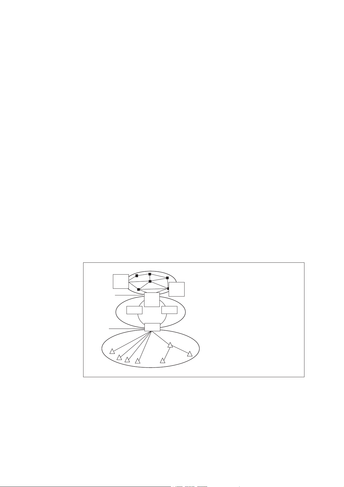
A mobile transmission network is by far the most common application of
MINI-LINK E and E Micro, where they are deployed in the Low Capacity Radio
Access Network ( LRAN).
MSC - Mobile Switching Center
MG - Media Gateway
BSC - Base Station Controller
RNC - Radio Node Controller
5558
Switch site
Transmission
hub site
MSC/
MG
HUB
BSC/
RNC
HUB
MSC/
MG
HUB
Core Network
High Capacity Radio
Access Network
(HRAN)
Low Capacity Radio
Access Network
(LRAN)
Figure 1 A mobile transmission network
2
AE/LZT 110 2012 R8C 2002-03-04
Page 9
MINI-LINKEandEMicro
MINI-LINK
Base station
MSC
BSC
Figure 2 Example of a mobile network, where MINI-LINK products connect
radio base stations to switching centers
3503
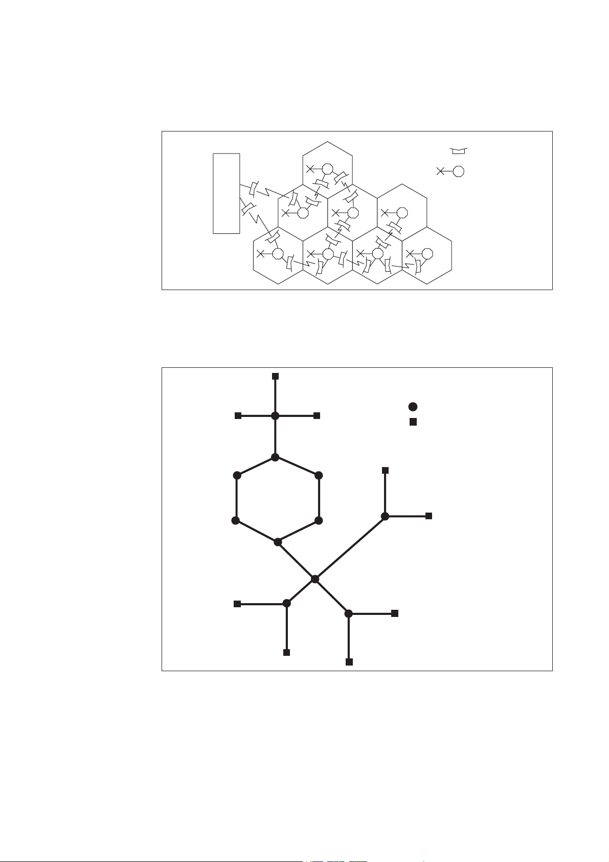
The figure below shows an example of how MINI-LINK E and E Micro can be
used in different network topologies.
Star
Ring
Tree
MINI-LINK E
MINI-LINK E Micro
Figure 3 Example of network topologies
AE/LZT 110 2012 R8C 2002-03-04
3500
3
Page 10
MINI-LINKEandEMicro
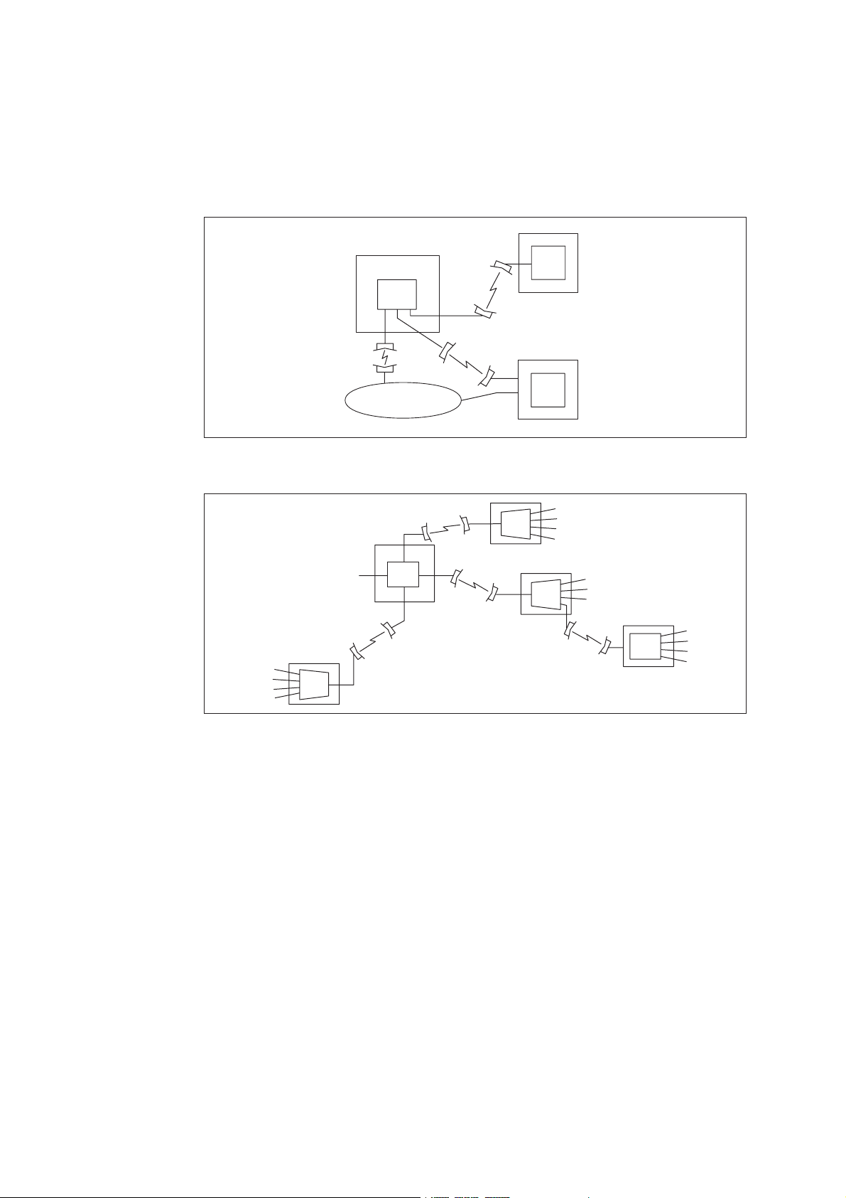
The following figures show applications in a pr ivate and fixed network.
PBX
PBX
Public
network
PBX
3501
Figure 4 Example of a private network, where MINI-LINK products connect
major sites
RSS
AXE
RSS
RSM
RSS
3502
Figure 5 Example of a fixed network using AXE systems, where remote
subscriber access units are connected to the network with MINI-LINK products
4
AE/LZT 110 2012 R8C 2002-03-04
Page 11

1.3 Main Features
Technical features
• Extremely compact and integrated design
• The radio and antenna form an integrated outdoor part
• High system gain and spectrum utilization with an advanced m odulation
process and coding
• 2 to 17x2 (34+2) Mbit/s traffic capacity
• Software tool for easy installation
• Advanced element manager
MINI-LINKEandEMicro
• Standardized interfaces
• Low weight and power consumption
Reliability
• High Mean Time Between Failure ( MTBF)
• Progress with backward compatibility
• Part of the Ericsson system portfolio
• 30 years’ experience of microwave transmission
• World’s largest production of microwave transmission systems
• MINI-LINK equipment can cope with extreme environments
Services
• Ericsson turnkey capability
• Customer training programs worldwide
• Total field maintenance services
• Ericsson local presence in more than 140 countries
AE/LZT 110 2012 R8C 2002-03-04
5
Page 12

MINI-LINKEandEMicro
1.4 Related Documents
This section gives an overview of some MINI-LINK E and E Micro related
documents. The documents can be ordered separately and can also be
downloaded from the Ericsson Intranet and customer Extranet portals.
MINI-LINK E and E Micro Product Catalog (AE/LZT 110 2011)
The product catalog is intended to be an aid when compiling an order or just
to give a more detailed overview of the products in the MINI-LINK E and E
Micro product families.
Netman Technical Description (AE/LZT 110 5048)
The document describes the technical features of the element management
system Netman.
MINI-LINK E and E Micro Planning and Engineering Manual (EN/LZT 110
2013)
The manual is used for planning and engineering of a MINI-LINK E and E Micro
network.
6
AE/LZT 110 2012 R8C 2002-03-04
Page 13
2 Product Program
2.1 Introduction
A terminal is one side of a microwave radio link hop, between two geographical
locations. The networks of today contain both single terminal sites and more
complex multi-terminal sites. MINI-LINK E and E Micro feature these types of
terminal configurations, further described in this chapter.
MINI-LINKEandEMicro
MINI-LINK E
Antenna
Radio
unit
Access
module
To operator
equipment
Radio
unit
operator equipment
Figure 6 Two examples of terminal configuration
MINI-LINK E Micro
Antenna
To all-outdoor
5500
AE/LZT 110 2012 R8C 2002-03-04
7
Page 14
MINI-LINKEandEMicro
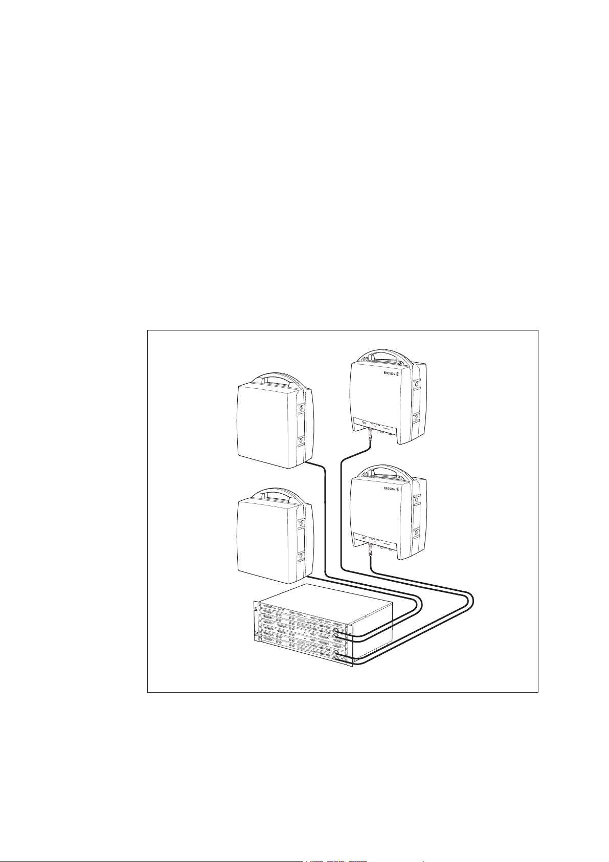
2.2 MINI-LINK E
Several M INI-LINK E terminals can be integrated into one common access
module. This enables extremely compact network sites as well as efficient
sharing of resources between different terminals, such as multiplexers, service
channel interfaces and support systems.
Traffic routing and re-routing within a network site can be performed with a
minimum of external cables. Traffic routing is software configured during station
setup.
Terminals can be configured for unprotected (1+0), protected (1+1) terminals
or ring protection.
Each terminal provides traffic capacity for up to 17x2 (34+2) Mbit/s.
3522
Figure 7 A MINI-LINK E multi-terminal site
8
AE/LZT 110 2012 R8C 2002-03-04
Page 15

2.2.1 System Components
Figure 8 The main parts of a MINI-LINK E terminal
Radio
unit
Access
module
To operator
equipment
MINI-LINKEandEMicro
Antenna
3520
A MINI-LINK E terminal consists of an outdoor and indoor part. There are also
a number of well-adapted accessories, both hardware and software.
Outdoor Part
The outdoor part is fully independent of traffic capacity and supplied for various
frequency bands.
It consists of an antenna module, a Radio Unit (RAU) and associated
installation hardware. The antenna and the radio unit are either integrated or
installed separately. For protected systems (1+1), two radio units and one or
two antennas are used.
Indoor Part
The indoor part, the access module, is fully independent of frequency band
and supplied in different versions for various traffic capacities and system
configurations. It can support up to four radios.
It consists of a Modem Unit (MMU) and an optional Switch Multiplexer Unit
(SMU), as well as an optional Service Access Unit (SAU), all housed in one
common Access Module Magazine (AMM). For protected systems, two MMUs
and one SMU are used.
The indoor part is connected to the outdoor part with a single coaxial cable
(the radio cable).
For Ethernet traffic the optional ETU can be used, see Section 3.11 on page 69.
For ring protection the optional MINI-LINK Cross-connect Unit (MXU) can be
used, see Section 7.2 on page 115.
AE/LZT 110 2012 R8C 2002-03-04
9
Page 16
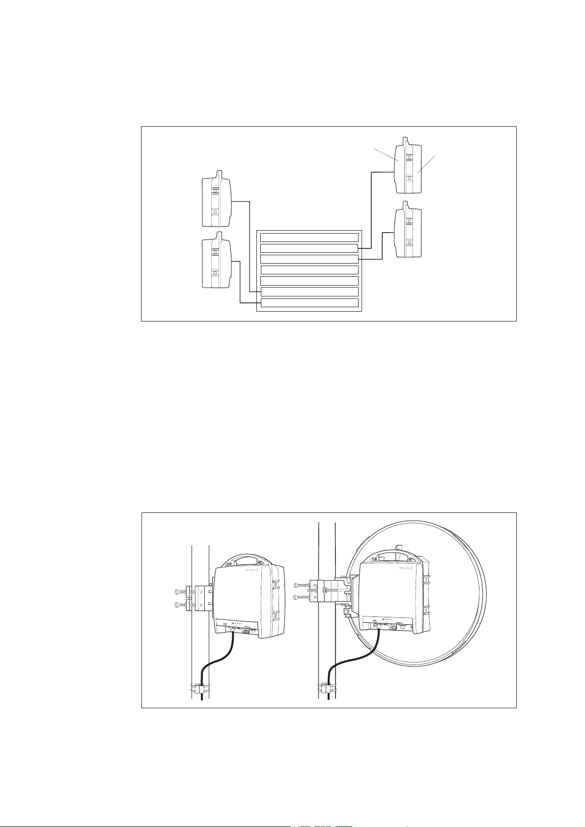
MINI-LINKEandEMicro
Access module
(SAU)
MMU
MMU
SMU
SMU
MMU
MMU
Radio
unit
Antenna
3507
Figure 9 A multi-terminal site
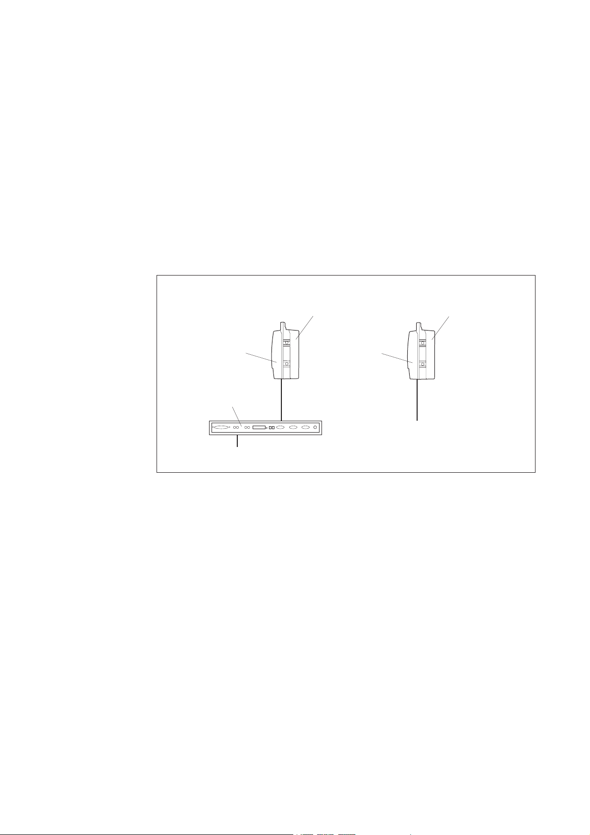
2.2.2 Outdoor Installation
The radio unit and the antenna are easily installed on a wide range of support
structures.
The radio unit is fitted directly to the antenna as standard, integrated installation.
The radio unit and the antenna can also be fitted separately and connected by
a flexible waveguide.
In both cases, the antenna is easily aligned and the radio unit can be
disconnected and replaced without affecting the antenna alignment.
10
3519
Figure 10 The radio unit fitted directly to a 0.2 m compact antenna and a
0.6 m compact antenna respectively
AE/LZT 110 2012 R8C 2002-03-04
Page 17
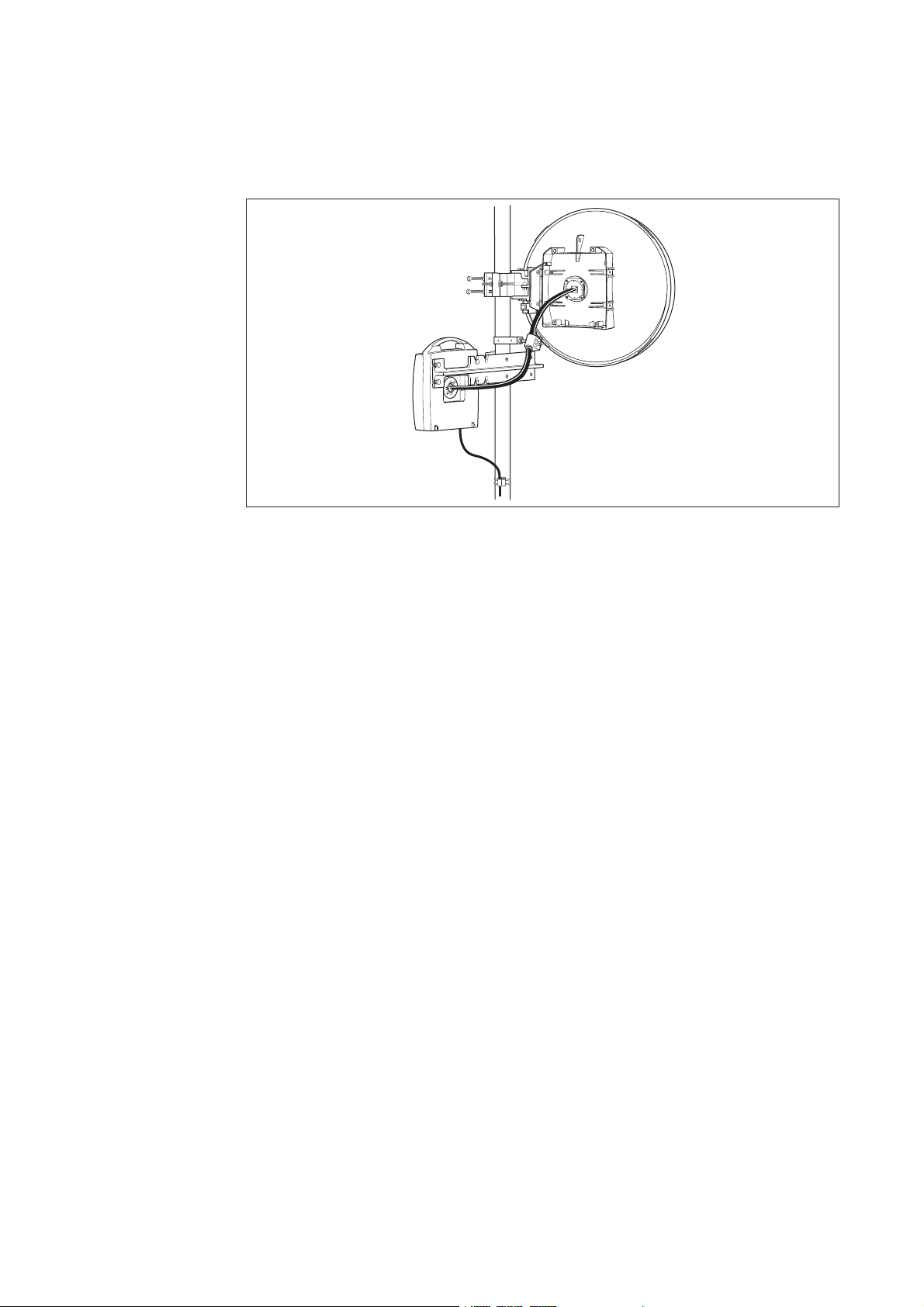
MINI-LINKEandEMicro
3508
Figure 11 The radio unit and a 0.6 m compact antenna fitted separately
2.2.3 Indoor Installation
The indoor parts are fitted in 19" racks, in ETSI and BYB cabinets or directly
on the wall/desk. An access module consists of an Access Module M agazine
(AMM) and a set of different plug-in units. The following AMMs for different
applications are available as standard:
• AMM 1U for end terminals
• AMM 2U-3 for single or dual terminal sites, containing up to four plug-in units
• AMM 4U for more complex, multi-terminal sites, containing up to seven
plug-in units
The indoor part can be upgraded or reconfigured with plug-in units, providing
site flexibility.
The interconnection between the outdoor part (radio unit and antenna) and
the indoor part is a single coaxial cable carr ying full duplex traffic, DC supply
voltage, service traffic as well as operation and maintenance data.
AE/LZT 110 2012 R8C 2002-03-04
11
Page 18
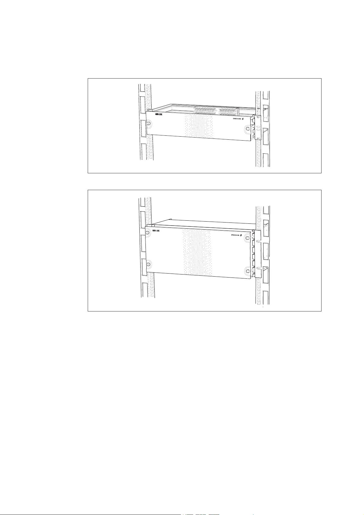
MINI-LINKEandEMicro
Figure 12 The AMM 2U-3 for a maximum of four units
3514
Figure 13 The AMM 4U for a maximum of seven units
1234
12
AE/LZT 110 2012 R8C 2002-03-04
Page 19
2.2.4 Configurations
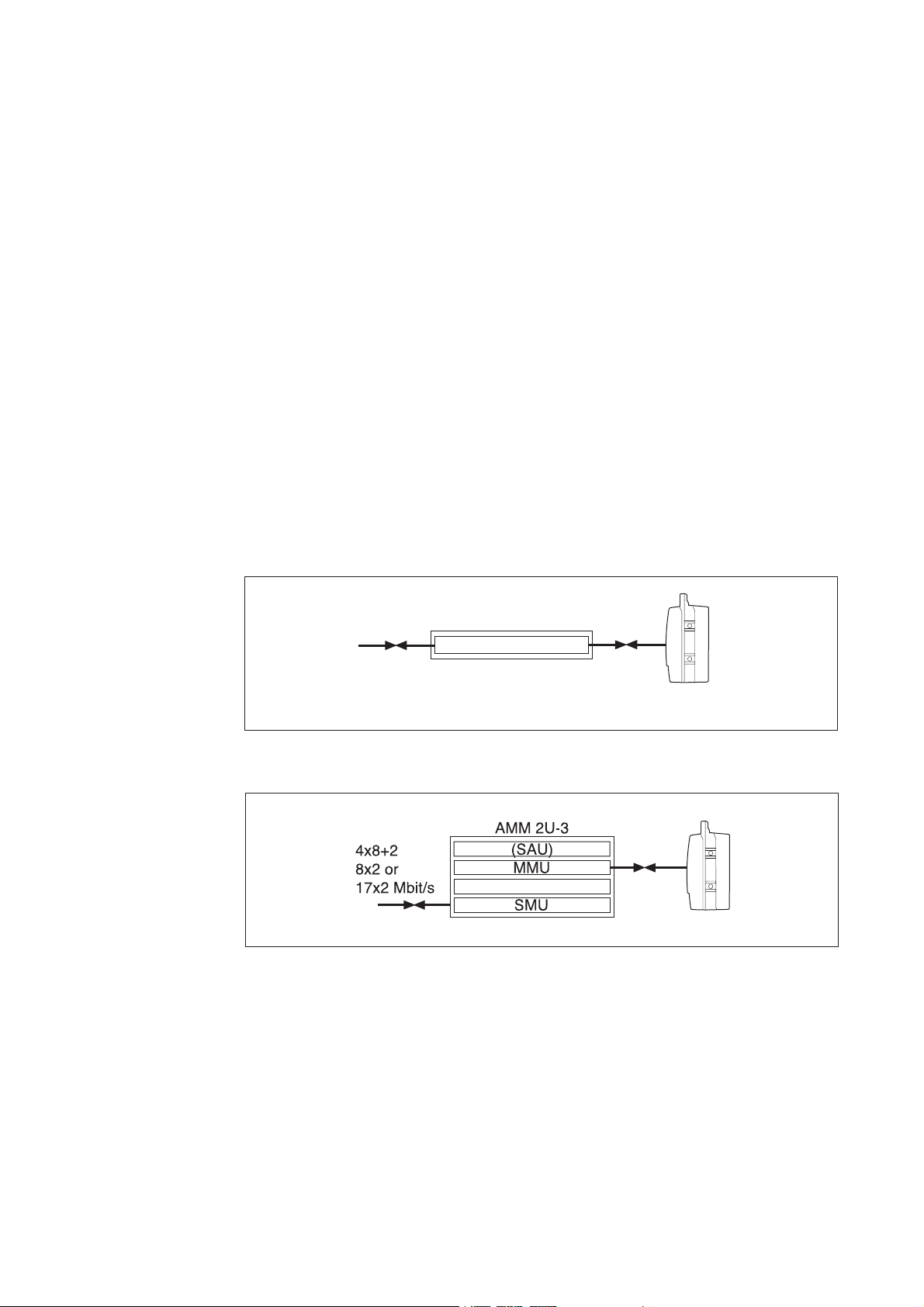
2.2.4.1 Unprotected Terminal (1+0)
As a minimum a 1+0 terminal consists of:
•RAU
• Antenna
•AMM1U
• MMU
• Coaxial cable for interconnection
MINI-LINKEandEMicro
For traffic capacities 8x2, 17x2 and 4x8+2, an SMU is required. An SAU can be
added to the AMM to provide additional alarm and control interfaces, service
channels and other customer specific applications.
AMM 1U
MMU
2x2, 4x2,
8, 2x8 or
34+2 Mbit/s
3510
Figure 14 1+0 configuration. The MMU can be installed in an AMM 1U
(AMM 2U-3 if SAU is required).
4492
Figure 15 1+0 configuration for 8x2, 4x8+2 and 17x2 Mbit/s capacities
AE/LZT 110 2012 R8C 2002-03-04
13
Page 20
MINI-LINKEandEMicro
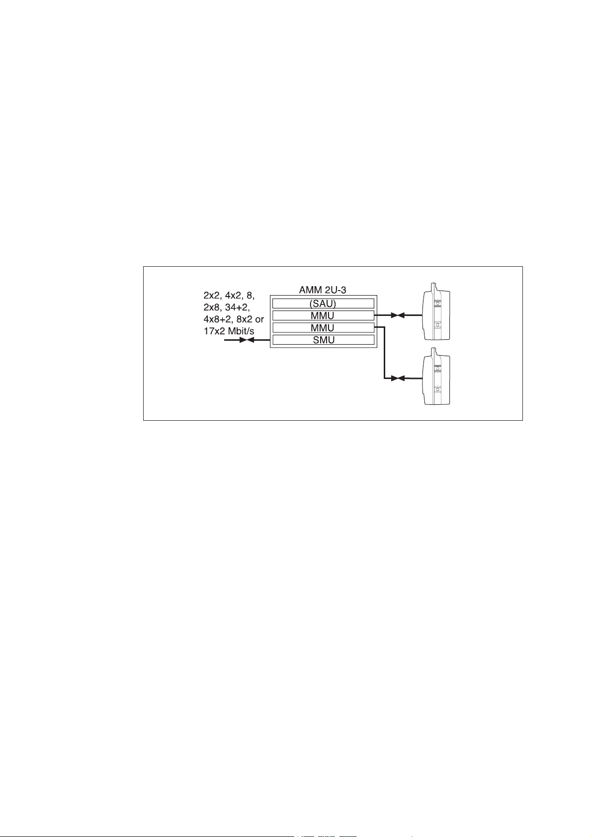
2.2.4.2 Protected Terminal (1+1)
As a minimum, a 1+1 terminal consists of:
• Two RAUs
• Two antennas or one antenna with a power splitter
• One AMM 2U-3 (or AMM 4U) with two MMUs and one SMU
• Two coaxial cables for interconnection
4493
Figure 16 1+1 configuration requires an AMM 2U-3 (AMM 4U can be used
as an alternative)
An SAU can also be added to the AMM to provide additional alarm and control
interfaces, ser vice channels and other customer specific applications.
The radio units can be equipped with individual antennas or connected to a
common antenna. In the case of one common antenna, the two radio units
are connected by waveguides to a power splitter, fitted on a single-polarized
antenna.
Automatic switching can be in hot standby or in working standby (frequency
diversity). Receiver switching in space diversity systems is hitless.
In hot standby mode, one transmitter is working while the other one is in
standby (that is, not transmitting but ready to transmit if the active transmitter
malfunctions). Both radio units are receiving signals. The MMU selects the
best signal according to an alarm priority list, connects it first to the SMU for
demultiplexing and then to external equipment. See Section 3.9.2.6 on page 58
for fur ther information about switching.
In working standby mode, both radio paths are active in parallel using different
frequencies.
14
The 1+1 configuration should be considered for important and/or heavy traffic
requiring high availability, but also if there are severe reflections and/or harsh
atmospheric conditions.
AE/LZT 110 2012 R8C 2002-03-04
Page 21
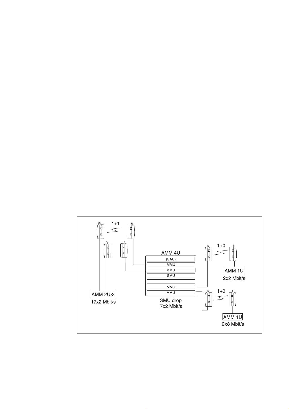
2.2.4.3 Configurations at Multi-terminal Sites
Several terminals can be integrated in the same indoor AMM. Different
configurations, traffic capacities and radio frequencies can be combined. A site
can be upgraded easily by substituting and/or adding plug-in units.
• One AMM 2U-3 c an hold:
− Two unprotected (1+0) terminals or one protected (1+1) terminal
− One SAU
• One AMM 4U can hold:
− Up to four unprotected (1+0) terminals
− Two protected (1+1) terminals
− One protected (1+1) terminal plus one or t wo unprotected (1+0)
terminals
− One SAU
MINI-LINKEandEMicro
Software controlled traffic routing between the terminals minimizes site cabling,
see S ection 3.12 on page 74.
One SMU can contain multiplexers/demultiplexers for two terminals. The
terminals can also share the same optional SAU. The SAU offers analog or
digital service channels as well as parallel inputs/outputs for integration of
alarms and external equipment control.
Figure 17 A multi-terminal site with drop of 7x2 Mbit/s
AE/LZT 110 2012 R8C 2002-03-04
4495
15
Page 22
MINI-LINKEandEMicro
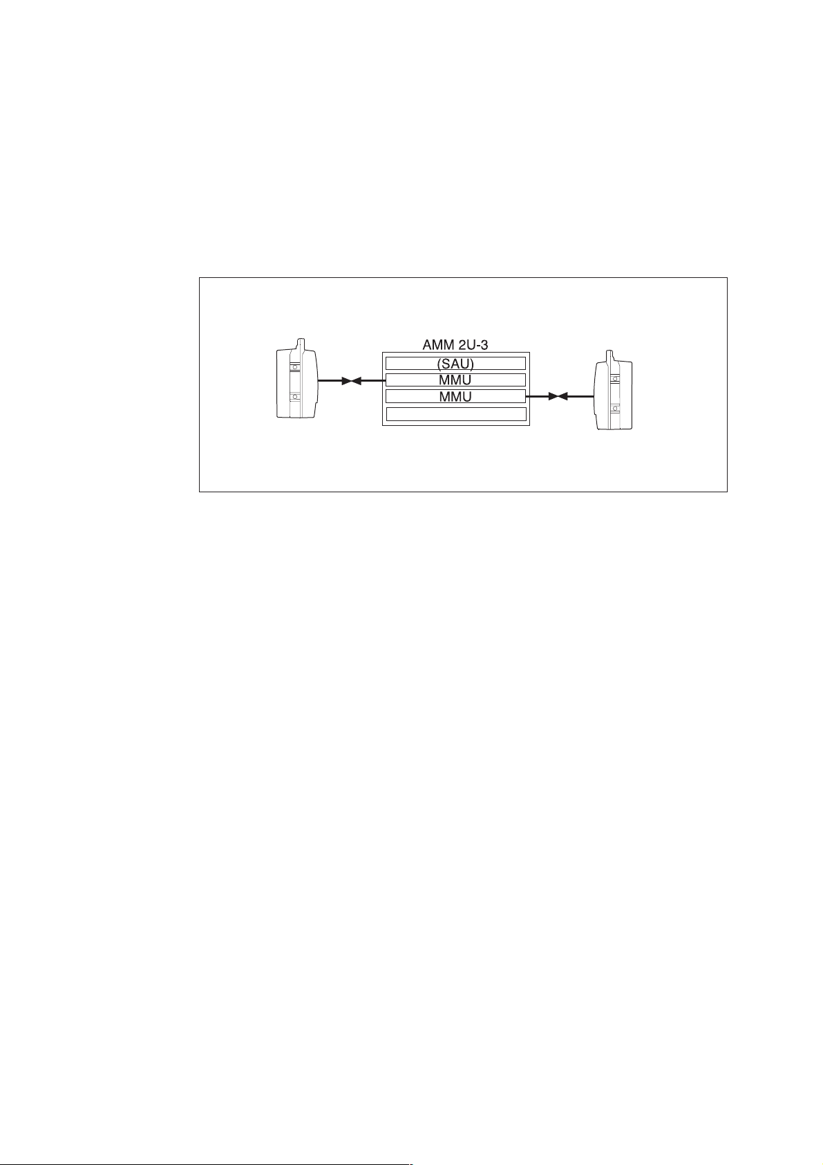
2.2.4.4 Repeater Site (1+0 or 1+1)
The repeater site basically comprises two terminals, back-to-back. The two
radio units are connected by using two MMUs in the same access module
without any external cables.
Figure 18 A 1+0 repeater site
Drop/Insert
If one or more traffic signals are to be dropped and/or inserted at the repeater
site, this can be accomplished either directly at the MMUs, provided that M MUs
with 2 Mbit/s interfaces are selected or by including an SMU on the site.
An SAU can be added to the AMM to provide additional alarm and control
interfaces, ser vice channels and other customer specific applications.
2.2.4.5 Ring Protection
An MX U added to the AMM enables ring protection. For further information,
see Section 7.2 on page 115.
4496
16
AE/LZT 110 2012 R8C 2002-03-04
Page 23
2.2.4.6 Ethernet Traffic
An ETU added to the AMM enables transmission of Ethernet traffic. The typical
application of the ETU is LAN-to-LAN interconnection using the following site
configuration:
•RAU
• Antenna
•AMM2U-3
•ETU
• MMU
• Coaxial cable for interconnection
MINI-LINKEandEMicro
AMM 2U-3
10BASE-T/100BASE-TX
n x E1/E2
ETU
MMU
5505
Figure 19 Typical site configuration using ETU for LAN-to-LAN interconnection
with optional PDH traffic connected to the MMU
The ETU can also be used in a protected (1+1) terminal configuration or in
multi-terminal configurations.
For more information on the ETU, see Section 3.11 on page 69.
AE/LZT 110 2012 R8C 2002-03-04
17
Page 24

MINI-LINKEandEMicro
2.3 MINI-LINK E Micro
MINI-LINK E Micro is a ver y small and easily installed all-outdoor radio, housing
all transmission components. It can be used at all-outdoor sites with up to three
unprotected (1+0) connections and provides traffic capacity for up to 2x2 Mbits.
The traffic interface has long-haul capabilities, allowing a cable length that
enables flexible installation of the terminal.
A terminal consists of an outdoor radio unit (RTU), an antenna and an optional
Radio Connection Box (RCB).
For more information on MINI-LINK E Micro, see Section 4 on page 79.
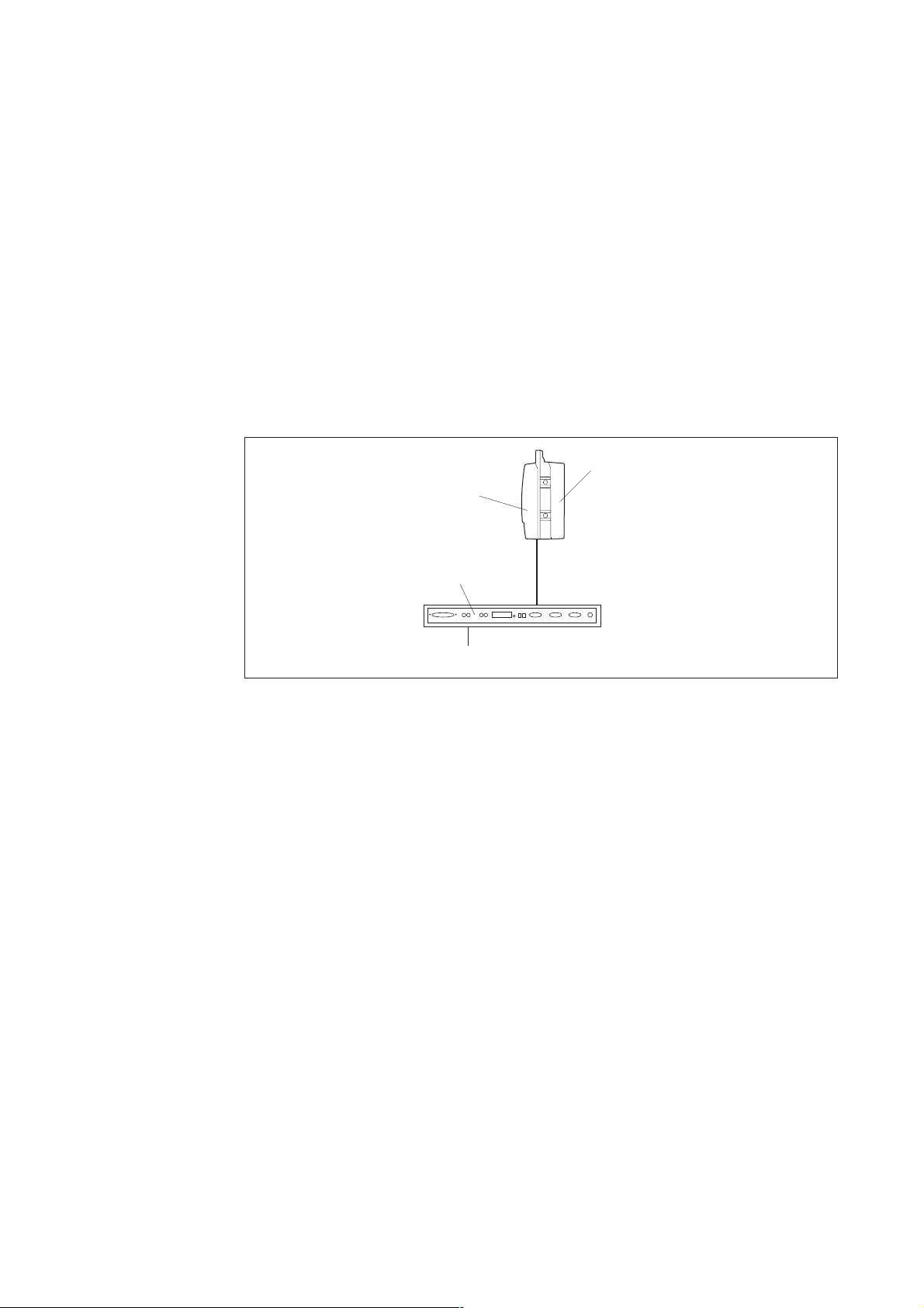
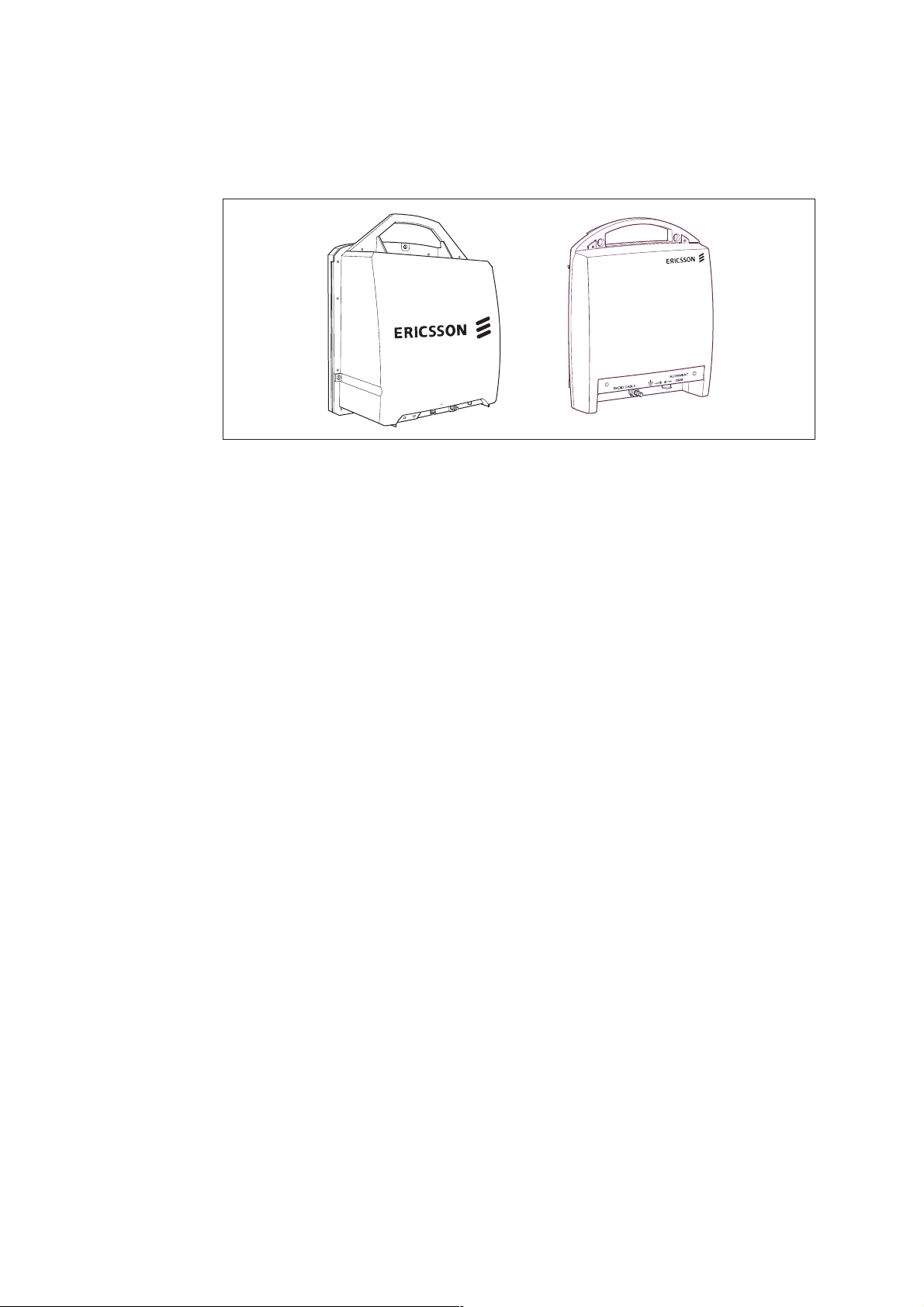
Figure 20 M INI-LINK E Micro with a 0.2 m compact antenna
2.3.1 Configurations
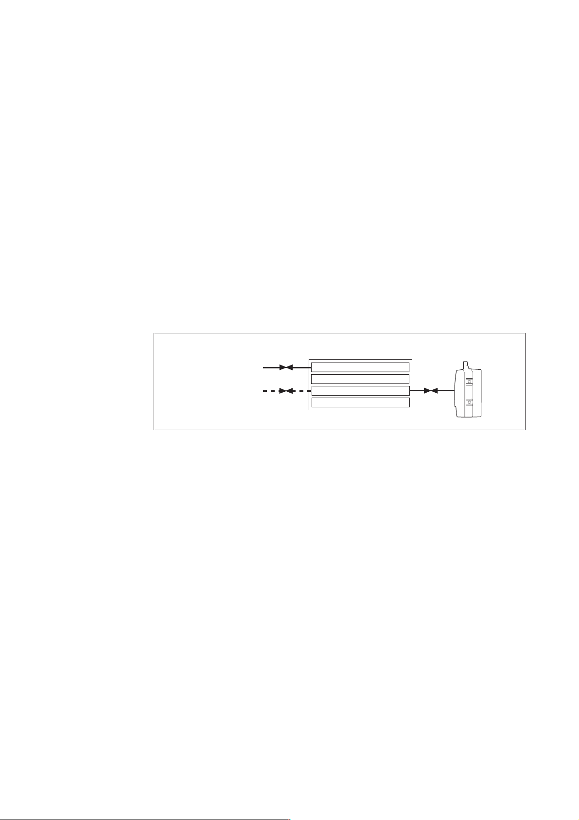
Figure 21 A MINI-LINK E Micro terminal with traffic and DC cables
MINI-LINK E Micro has standardized t raffic interfaces for 2 or 2x2 Mbit/s (only
2x2 Mbit/s for the 38 GHz version).
Traffic
DC
3521
3518
18
AE/LZT 110 2012 R8C 2002-03-04
Page 25
MINI-LINKEandEMicro
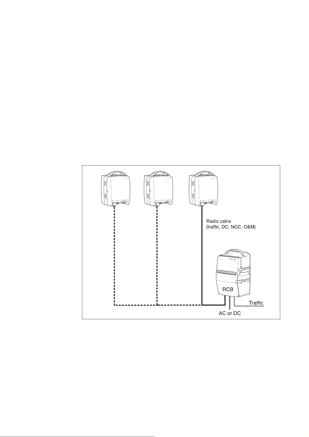
The terminal can be DC or AC powered. On sites with only one terminal, traffic
and DC can be directly connected with two cables. On sites with more than one
terminal or where no DC supply is available, a Radio Connection Box (RCB) is
required. For more information, see Section 7.1 on page 113.
The gray painted radio unit fits onto the back of the antenna, but can equally
well be installed separately from the antenna and connected with a waveguide
feeder.
Applications for MINI-LINK E Micro are in mobile telephony, business access,
PBX (Private Branch eXchange), and data networks together with any outdoor
installed telecom equipment.
It can be used as an end-terminal or when using the RCB as a repeater or
multi-terminal site.
Figure 22 MINI-LINK E M icro with RCB, multi-terminal site
3517
19AE/LZT 110 2012 R8C 2002-03-04
Page 26
MINI-LINKEandEMicro
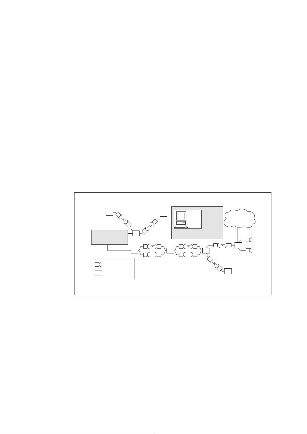
2.4 Network Management
The maintenance features enable flexible and easy setup and facilitate
faultfinding and repair. N etwork management features are:
• Alarm transfer channel
• Performance monitoring
• Near and far-end loop-back tests
• Data and voice service channels
• Software controlled routing of traffic
• Software selectable output power and frequency
• Remote software upgrade
• Capacity agile MMU configuration
PSTN back-up
or other line
Leased line or
other fixed channel
Radio Unit/
Antenna Module
Access Module
Operation & maintenance
centre
3509
Figure 23 MINI-LINK network management
A microprocessor monitors all functional alarms and transmits them on an
Operation & Maintenance channel, which extends throughout the sub-network.
MINI-LINK Netman can be used for central supervision of the equipment in a
network.
Easy Access at Any Location
The service engineer can access the Operation & Maintenance channel
for functional alarms at any location. He thus gets an overview of t he
network status by using a PC with the MINI-LINK Service Manager (MSM)
software. The service engineer can also reconfigure the traffic routing, check
performance data or switch between operating and standby equipment. He
20 AE/LZT 110 2012 R8C 2002-03-04
Page 27

MINI-LINKEandEMicro
can also command near-end and far-end loop-backs to be performed. Local
configuration of the capacity agile MMU at the near-end can be carried out
as well.
Local Management
The local supervision interface on the MMU enables fault finding and
measurement when a PC is not available.
Service Channel
The integrated maintenance system is optionally supplemented with two service
channels. These service channels may be configured as digital data channels
(64 kbit/s) or as omnibus voice channels with a built-in telephone interface.
AE/LZT 110 2012 R8C 2002-03-04
21
Page 28

MINI-LINKEandEMicro
22 AE/LZT 110 2012 R8C 2002-03-04
Page 29
3MINI-LINKE
3.1 General
MINI-LINK E comprises an indoor access module, an outdoor radio unit with
antenna and mounting kit. The radio unit is connected to the indoor unit with
a single coaxial cable and can be combined with a wide range of antennas
for integrated or separate installation.
Radio
unit
MINI-LINKEandEMicro
Antenna
Figure 24 MINI-LINK E terminal
3.2 Radio Units
The radio units are continuously developed and improved regarding design
and technology. Two types of radio unit are available, RAU1 and RAU2. They
have the same functionality, but different mechanical design and microwave
technology. RAU2 has a higher integration of microwave circuits.
The radio units are independent of traffic capacity, that is the operating
frequency is determined by the radio unit only. The operating frequency is set
on site. This is done with the management software products or with a toggle
switch on the indoor MMU.
The radio unit is a weatherproof box painted light gray, with a handle for lifting
and hoisting. It connects to the antenna unit at the waveguide port. The radio
unit also has two hooks and catches to guide it for easier handling, when fitting
to or removing from an integrated antenna.
Access
module
To operator
equipment
3520
Radio units are available for different frequency channel arrangements
according to ITU-R and ETSI recommendations. For detailed information on
frequency versions, see Section 8 on page 125 and the MINI-LINK E and E
Micro Product Catalog (AE/LZT 110 2011).
AE/LZT 110 2012 R8C 2002-03-04
23
Page 30
MINI-LINKEandEMicro
Figure 25 The RAU1 and RAU2 radio units
3531
24
AE/LZT 110 2012 R8C 2002-03-04
Page 31

3.3 RAU1 (7-E and 8-E)
This radio unit contains frame, cover, microwave sub-unit and filter unit.
The vertical frame has a waveguide interface for connection to the antenna.
The bottom of the cover carr ies the radio cable connector that is the interface
with the indoor modem unit (MMU), and a test port for antenna alignment.
The connector for the radio cable is equipped with gas discharge tubes for
lightning protection.
Replacing the filter unit can change the sub-band for a radio within a group of
sub-bands. For more information, see the MINI-LINK E and E Micro Product
Catalog (AE/LZT 110 2011), chapter Radio Units.
MINI-LINKEandEMicro
Figure 26 RAU1 for 7 and 8 GHz
5315
AE/LZT 110 2012 R8C 2002-03-04
25
Page 32

MINI-LINKEandEMicro
3.3.1 Block Diagram
MMU
Microwave Sub-unit
Transmit IF
Signal,
350 MHz
Receive IF
Signal,
140 MHz
Cable Interface
Command
& Control
Signal
Transmit IF
Signal
Processing
Receive IF
Signal
Processing
Control &
Supervision
Processor
Transmitter
To
Alignment Port
DC/DC Converter
Up
Converter
Transmitter
Oscillator
FREQUENCY
CONTROL
Receiver
Amplifier
Down
Converter
Filter
&
Amplifier
Output
Level
Control
FREQUENCY
CONTROL
Receiver
Oscillator
Low
Noise
Amplifier
Alarm
and
Control
Final
TX OFF
OUTPUT
LEVEL SET
Secondary
Voltages
Power
Detector
RF Loop
RF Attenuator
(accessory)
Filter
Unit
Branching
Filter
Antenna
Branching
Filter
3538
Figure 27 RAU1 7-E and 8-E block diagram
3.3.2 Microwave Sub-unit
The following functions are in
• DC/DC Converter
• Cable interface
• Control and supervision
• Transmit signal processing
• Receive signal processing
The microwave sub-unit consists of a microstrip board with an aluminum cover
that provides shielded compartments for the high-frequency circuits. The
control circuit board is fitted t o the back of the microstrip board.
The microwave sub-unit is fully independent of transmission rates.
A microwave sub-unit covers several sub-bands. The sub-band is defined by
the microwave sub-unit together with the filter unit.
cluded in the microwave sub-unit:
26
AE/LZT 110 2012 R8C 2002-03-04
Page 33

3.3.2.1 DC/DC Converter
The DC/DC converter provides stable voltages for the microwave sub-unit.
3.3.2.2 Cable Interface
The incoming composite signals from the indoor units, that is, transmitting IF
signal, command and control signal and DC, are demultiplexed in the cable
interface and forwarded for further processing.
• The transmitting IF signal is a modulated signal with a nominal frequency
of 350 MHz.
• The command and control signal up-link is an ASK (Amplitude Shift Keying)
modulated signal with a nominal frequency of 6.5 MHz.
MINI-LINKEandEMicro
• The DC feed is in the range of 45 – 60 V DC (24 – 60 V DC, nominal,
is connected to the MMU).
Similarly, the outgoing signals are multiplexed in the cable interface: receiving
IF signal and command and control signal down-link.
• The nominal frequency of the receiving IF signal is 140 MH z.
• The command and control signal down-link is an ASK modulated signal
with a nominal frequency of 4.5 MHz.
In addition to the above, the cable interface includes an overvoltage protection
circuit.
3.3.2.3 Control and Supervision Processor
The microwave sub-unit houses the processor for control and supervision of the
radio unit. The main functions of this processor are described below.
Alarm Collection
Collected alarms and status signals from the radio unit are sent to the indoor
MMU processor. Sum mary status signals are visualized by LEDs on the radio
unit.
Command Handling
Commands from the indoor units are executed. These commands include
transmitter activation/deactivation, channel frequency settings, output power
settings and RF loop activation/deactivation.
Radio Unit Control
The processor also controls the radio unit’s internal processes and loops.
AE/LZT 110 2012 R8C 2002-03-04
27
Page 34

MINI-LINKEandEMicro
3.3.2.4 Transmit IF Signal Processing
The input amplifier is automatically gain-controlled so that no compensation is
required due to the cable length between indoor and outdoor equipment.
The level is used to generate an alarm, indicating that the transmitting IF signal
level is too low due to excessive cable losses.
3.3.2.5 Transmitter Block
Upconverter
The transmitting IF signal is amplified and up-converted to 7 GHz / 8 GHz
in the transmitter.
Transmitter Oscillator
The frequency of the transmitter is controlled in a Phase Locked Loop (PLL) (a
sample of the VCO signal is fed to a divider and further on to a programmable
phase detector). The error signal is controlled by the integrated control and
supervision system by using a serial bus. An unlocked VC O loop generates a
transmitter frequency alarm.
Final Amplifier
The transmitter output power is controlled by adjusting the gain of the final
amplifier. The output power is set in steps of 1 dB through the operation and
maintenance system. The transmitter can be switched on or off by switching
the final amplifier.
3.3.2.6 Power Detector
A sample of the transmission signal is used for supervision of the transmitted
power (output power alarm).
3.3.2.7 RF Loop
A sample of the transmission signal is mixed with a shift oscillator signal and is
fed into the receiver for test purposes.
3.3.2.8 RF Attenuation
In addition to the transmitter output power control described above, the output
RF level may be further decreased by fitting fixed RF attenuators to the
microwave unit. The transmitted RF can then be attenuated by a total of 50 dB.
See Section 8.1.1 on page 126 for more details.
28
AE/LZT 110 2012 R8C 2002-03-04
Page 35

3.3.2.9 Receiver Block
The received signal is fed from the input branching filter into a low noise
amplifier and down-converted to 140 MHz.
Receiver Oscillator and Filter
An LO signal for the down-conversion is generated in the same way as for the
transmitted signal. A frequency error signal from the MMU is used to shift the
receiver VCO in order to facilitate an AFC-loop.
3.3.2.10 Receive IF Signal Processing
The 140 MHz receiving IF signal from the receiver is amplified and fed to the
cable interface. Additionally, a portion of the signal is fed to a calibrated detector
to provide an accurate receiver input level measurement. The measured level is
accessible either as an analog voltage at the alignment port or in dBm through
the operation and maintenance system.
MINI-LINKEandEMicro
3.3.3 Filter Unit
Branching Filter
On the transmitting side, the signal is fed to the antenna through an output
branching filter. The signal from the antenna is fed to the receiving side through
an input branching filter. The antenna and both branching filters are connected
with an impedance T-junction.
AE/LZT 110 2012 R8C 2002-03-04
29
Page 36

MINI-LINKEandEMicro
3.4 RAU1 (15-E, 18-E, 2 3-E, 26-E and 38-E)
This radio unit contains cover, frame, a radio interface sub-unit and a microwave
sub-unit.
The radio interface sub-unit consists of a circuit board assembly, including
external interfaces with the indoor units. This interface is a 50
connector. A connector for RF input level measurements and a set of LEDs
are accessible from the outside of the radio unit. The microwave sub-unit
consists of a microstrip board w ith an aluminum cover that provides shielded
compartments for the high-frequency circuits. The control circuit board is
fitted at the back of the microstrip board. The microwave sub-unit provides a
waveguide interface with the antenna.
The DC/DC converter is fitted directly on the vertical frame and connected to
the m icrowave sub-unit by a flat cable.
N-type
The vertical frame also has a waveguide port for connection to the antenna.
The bottom of the cover carries the radio cable connector, which is the interface
with the indoor modem unit (MMU), and a test port for antenna alignment.
The connector for the radio cable is equipped with gas discharge tubes for
lightning protection.
3555
Figure 28 RAU1 15-E, 18-E, 23-E, 26-E and 38-E
30
AE/LZT 110 2012 R8C 2002-03-04
Page 37

3.4.1 Block Diagram
MINI-LINKEandEMicro
Radio Interface Sub-unit
MMU
Transmit IF
Signal,
350 MHz
Receive IF
Signal,
140 MHz
Cable Interface
Command
& Control
Signal
Transmit IF
Signal
Processing
Receive IF
Signal
Processing
Control &
Supervision
Processor
DC
To
Alig nment Port
Microwave Sub-unit
FREQUENCY
CONTROL
Receiver
FREQUENCY
CONTROL
AFC
Receiver
Oscillator
Converter
Transmitter
Transmitter
Oscillator
Down
Alarm and Control
Multiplier
Filter &
Amplifier
First IF
around 1000 MHz
DC/DC Converter
& Filter
Multiplier
and
Filtering
Down
Converter
Final
Amplifier
Output
Level
Control
15, 23 and
26 high power
OUTPUT
LEVEL SET
Low
Noise
Amplifier
Not 38 GHz
Secondary
voltages
TX OFF
Power
Detector
RF Loop
15,18 and
23 GHz
Branching
Filter
RF Attenuator
(accessory)
Branching
Filter
Antenna
3537
Figure 29 RAU1 15-E, 18-E, 23-E, 26-E and 38-E block diagr
3.4.2 Radio Interface Sub-unit
The following functions are included in the radio interface sub-unit:
• Cable interface
• Control and supervision
• Transmit IF signal processing
• Receive IF signal processing
3.4.2.1 Cable Interface
The incoming composite signals from the indoor units, that is, transmitting IF
signal, command and control signal and DC, are demultiplexed in the cable
interface and forwarded for further processing.
• The transmitting IF signal is a modulated signal with a nominal frequency
of 350 MHz
am
AE/LZT 110 2012 R8C 2002-03-04
31
Page 38

MINI-LINKEandEMicro
• The command and control signal up-link is an ASK (Amplitude Shift Keying)
• The DC feed is in the range of 45 – 60 V DC (24 – 60 V DC, nominal,
Similarly, the outgoing signals are multiplexed in the cable interface: receiving
IF signal and comm and and control signal down-link.
• The nominal frequency of t he receiving IF signal is 140 MHz.
• The comm and and control signal down-link is an ASK modulated signal
In addition to the above, the cable interface includes an overvoltage protection
circuit.
modulated signal with a nominal frequency of 6.5 MHz.
is connected to the MMU)
with a nominal frequency of 4.5 MHz.
3.4.2.2 Control and Supervision Processor
The radio interface sub-unit houses the processor for control and supervision of
the radio unit. The main functions of this processor are described below.
Alarm Collection
Collected alarms and status signals from the radio unit are sent to the indoor
MMU processor. Summary status signals are visualized by LEDs on the radio
unit.
Command Handling
Commands from the indoor units are executed. These commands include
transmitter activation/deactivation, channel frequency settings, output power
settings and RF loop activation/deactivation.
Radio Unit Control
In addition to the above, the processor controls the radio unit’s internal
processes and loops.
3.4.2.3 Transmit IF Signal Processing
32
The transmit IF signal is amplified, limited and demodulated. The dem odulated
signal is amplified and passed through a buffer amplifier to the microwave
sub-unit for modulation onto the RF carr ier.
The input amplifier is automatically gain-controlled so that no compensation is
required due to the cable length between indoor and outdoor equipment.
The level is used to generate an alarm, indicating that the transmitting IF signal
level is too low due to excessive cable losses.
AE/LZT 110 2012 R8C 2002-03-04
Page 39

3.4.2.4 Receive IF Signal Processing
The 140 MHz receive IF signal from the microwave sub-unit is amplified and fed
to the cable interface. Additionally, a portion of the signal is fed to a calibrated
detector to provide an accurate receiver input level measurement. The
measured level is accessible either as an analog voltage (AGC) at alignment
port or in dBm through the operation and maintenance system.
3.4.3 Microwave Sub-unit
3.4.3.1 DC/DC Converter
The DC/DC converter provides stable voltages for the microwave sub-unit as
well as for the radio interface unit.
MINI-LINKEandEMicro
3.4.3.2 Transmitter Block
Transmitter Oscillator
The frequency of the transmitter is controlled in a phase locked loop (PLL) (a
sample of the VCO signal is fed to a divider and further on to a programmable
phase detector). The error signal is controlled by the integrated control and
supervision system by using a serial bus. An unlocked VCO loop generates a
transmitter frequency alarm.
Multiplying and Filtering
The VCO signal is amplified, frequency multiplied and filtered.
Final Amplifier
The transmitter output power is controlled by adjusting the gain of the final
amplifier. The output power is set in steps of 1 dB through the operation and
maintenance system (Note: This applies to RAU1 15-E, 18-E, 23-E and 26-E
HP. RAU1 26-E and 38-E have a mechanical, adjustable attenuator adjacent
to the branching filter). The transmitter can be switched on or off by switching
the final amplifier.
Branching Filter
On the transmitting side, the signal is fed to the antenna through a branching
filter and a circulator. On the receiving side, the circulator feeds the received
signal to an input branching filter.
AE/LZT 110 2012 R8C 2002-03-04
33
Page 40

MINI-LINKEandEMicro
Power Detector
A sample of the transmission signal is used for supervision of the transmitted
power (output power alarm).
3.4.3.3 RF Loop (Only RAU1 15-E, 18-E and 23-E)
A sample of the transmission signal is mixed with a shift oscillator signal and is
fed into the receiver for test purposes.
3.4.3.4 RF Attenuation
In addition to the transmitter output power control described above, the output
RF level may be further decreased by fitting fixed RF attenuators to the
microwave unit. The transmitted RF can then be attenuated by a total of 50
dB for RAU1 23-E, 26-E and 38-E. For RAU1 15-E and 18-E, the transmitted
RF can be attenuated by a total of 33 dB. See Section 8.1.1 on page 126 for
more details.
3.4.3.5 Receiver Block
The received signal is fed from the input branching filter into a low noise
amplifier (with the exception of RAU1 38-E) and a down-converter to a first IF of
approximately 1 GHz. After bandpass filtering and amplification, the signal is
down-converted to the second IF of 140 MHz.
Receiver Oscillator, Multiplier and Filter
LO signals for the two down-conversions are generated in the same way as for
the transmitted signal. A frequency control signal from the MMU (AFC) is fed to
the receiver oscillator by the control and supervision processor.
This double superheterodyne receiver with a high first IF enables frequency
selection over a wide frequency band, w ith excellent receiver spurious and
image rejection.
34
AE/LZT 110 2012 R8C 2002-03-04
Page 41

3.5 RAU2
This radio unit consists of cover, frame, connection unit, microwave unit and
filter unit.
The connection unit forms the bottom of the radio unit cover and it holds alarm
indicators (LEDs) and connectors for traffic, grounding, DC power and antenna
alignment. The connection unit is also equipped with lightning protection.
The microwave unit is a circuit board assembly, consisting of a radio board
and two MCMs (Multi-chip M odule) for the transmitting and receiving parts
of the radio unit. The high-frequency MCM components are shielded with
an aluminum cover. In addition, it contains the cable interface, the DC/DC
converter, control and super vision functions and components for IF signal
processing.
MINI-LINKEandEMicro
The cable interface with the indoor units is a 50
N-type connector. The filter
unit consists of two branching filters and an impedance T-junction which is
the interface with the antenna.
Cover
Frame
Filter unit
Microwave unit
Figure 30 RAU2 parts
AE/LZT 110 2012 R8C 2002-03-04
Earthing screw
Connection unit
3548
35
Page 42

MINI-LINKEandEMicro
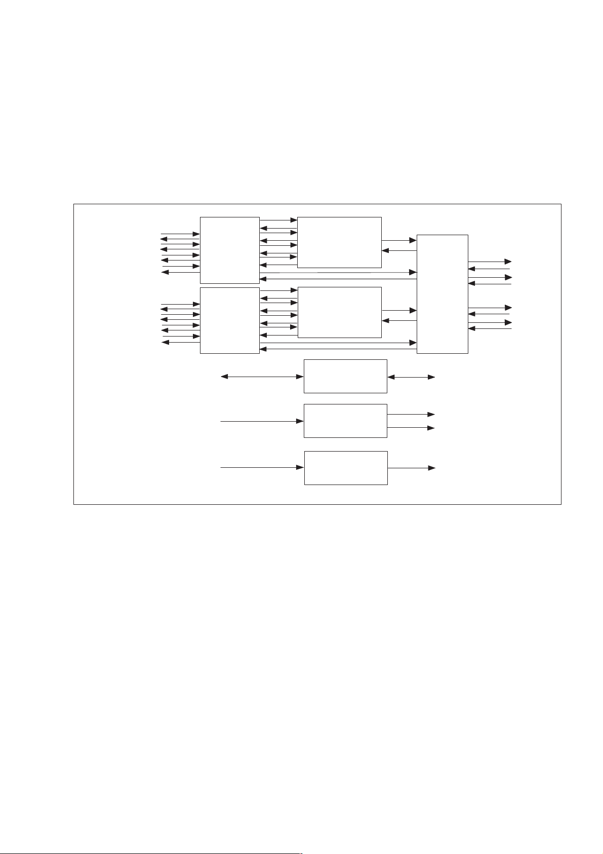
3.5.1 Block Diagram
MMU
Microwave Unit
Transmit IF
Signal,
350 MHz
DC
Receive IF
Signal,
140 MHz
Cable Interface
Command
& Control
Signal
To Alignment Port
Transmit IF
Signal
Processing
DC/DC Converter
RSSI
Control &
Supervision
Processor
Alarm and
Control
Secondary
voltages
FREQUENCY
CONTROL IF
140 MHz
FREQUENCY
CONTROL TX
Oscillator
834 MHz
Down
Converter
Transmitter ( MCM )
Transmitter
Oscillator
IF Converter
IF
Filter &
Amplifier
Multiplier
974 MHz
OUTPUT
LEVEL SET
Receiver
Oscillator
Multiplier
Down
Converter
Power
Amplifier
TX OFF
Output
Level
Control
Receiver ( MCM )
FREQUENCY
CONTROL RX
Low
Noise
Amplifier
RF
Loop
Filter Unit
Branching
Filter
Branching
Filter
Antenna
3539
Figure 31 RAU2 block diagram
3.5.2 Microwave Unit
3.5.2.1 DC/DC Converter
The DC/DC converter provides stable voltages for the radio unit.
3.5.2.2 Cable Interface
The incoming composite signals from the indoor units, that is, transmitting IF
signal, command and control signal and DC, are demultiplexed in the cable
interface and forwarded for further processing.
• The transmitting IF signal is a modulated signal with a nominal frequency
of 350 MHz
• The command and control signal up-link is an ASK (Amplitude Shift Keying)
modulated signal with a nominal frequency of 6.5 MHz.
• The DC feed is in the range of 45 – 60 V DC (24 – 60 V DC, nominal,
is connected to the MMU).
36
AE/LZT 110 2012 R8C 2002-03-04
Page 43

Similarly, the outgoing signals are multiplexed in the cable interface: receiving
IF signal and command and control signal down-link.
• The nominal frequency of the receiving IF signal is 140 MH z.
• The command and control signal down-link is an ASK modulated signal
with a nominal frequency of 4.5 MHz.
In addition to the above, the cable interface includes an overvoltage protection
circuit.
3.5.2.3 Control and Supervision Processor
The processor for radio unit control and supervision is situated on the
microwave unit circuit board. Its main functions are described below.
MINI-LINKEandEMicro
Alarm Collection
Collected alarms and status signals from the radio unit are sent to the indoor
MMU processor. Sum mary status signals are visualized by LEDs on the radio
unit.
Command Handling
Commands from the indoor units are executed. These commands include
transmitter activation/deactivation, channel frequency settings, output power
settings and RF loop activation/deactivation.
Radio Unit Control and Message Handling
The processor also controls the radio unit’s internal processes and loops.
3.5.2.4 Transmit IF Signal Processing
The transmit IF signal is amplified, limited and demodulated. The demodulated
signal is amplified and passed through a buffer amplifier to the transmitter MCM
for modulation onto the RF carrier.
The level is used to generate an alarm, indicating that the transmit IF signal
level is too low due to excessive cable losses.
The input amplifier is automatically gain-controlled so that no compensation is
required due to the cable length between indoor and outdoor equipment.
AE/LZT 110 2012 R8C 2002-03-04
37
Page 44

MINI-LINKEandEMicro
3.5.2.5 Transmitter Block
Transmitter Oscillator (MCM)
The frequency of the transmitter is controlled in a Phase Locked Loop (PLL) (a
sample of the VCO signal is fed to a divider and further on to a programmable
phase detector). An unlocked VCO loop generates a transmitter frequency
alarm.
Multiplier (MCM)
The VCO signal is amplified and frequency multiplied (2 or 4 times depending
on channel frequency).
Power Amplifier (MCM)
The transmitter output power is controlled by adjustment of the gain in the final
amplifier. The output power is set in steps of 1 dB through the operation and
maintenance system. The transmitter can be switched on or off by switching
the final amplifier.
3.5.2.6 Output Level Control
The output signal level from the final amplifiers are analyzed in order to see if
transmitted power is within specified range (output power alarm).
3.5.2.7 Receiver Block
The received signal is fed from the input branching filter into a low noise
amplifier and a down-converter to the first IF of 974 MHz (Receiver MCM).
After bandpass filtering and amplification, the signal is down-converted to the
second IF of 140 MHz (IF Converter). A portion of this 140 MHz is used in the
RSSI. The 140 MHz signal from IF Converter i s amplified and fed to the cable
interface. This double down-conversion with a high first IF enables frequency
selection over a wide frequency band, w ith excellent receiver spurious and
image rejection.
Receiver Oscillator and Multiplier (MCM)
The local oscillator signal used in the first down-conversion is generated in the
same way as for the transmitter oscillator. The signal is multiplied (2 or 4 times
depending on channel frequency) and amplified.
3.5.2.8 IF Oscillator
The oscillator consists of a Phase Locked Loop (PLL) and a VCO. It is used for
the second down-conversion to 140 MHz. The VCO is also used for adjustment
38
AE/LZT 110 2012 R8C 2002-03-04
Page 45

of the received 140 MHz signal (through a control signal effecting the division
number in the IF PLL).
3.5.2.9 RSSI
A portion of the 140 MHz signal is fed to a calibrated detector in the RSSI
(Received Signal Strength Indicator) to provide an accurate receiver input level
measurement. The measured level is accessible either as an analog voltage at
the alignment port or in dBm through the operation and maintenance system.
3.5.3 Filter Unit
3.5.3.1 RF Loop
The RF Loop is used for test purposes only. When the loop is set, the transmitter
frequency is set to receiver frequency and transferred to the receiving side.
MINI-LINKEandEMicro
3.5.3.2 Branching Filter
On the transmitting side, the signal is fed to the antenna through an output
branching filter. The signal from the antenna is fed to the receiving side through
an input branching filter. The antenna and both branching filters are connected
with an impedance T-junction.
AE/LZT 110 2012 R8C 2002-03-04
39
Page 46

MINI-LINKEandEMicro
3.6 Access Module
The access module is the indoor part of a terminal. It comprises the following
types of indoor equipment:
• Access Module Magazine (AMM), which holds the indoor plug-in units. The
AMM also provides mechanical housing and electrical interconnections
between indoor units through its backplane.
• Modem Unit (MMU) providing traffic interfaces, signal processing and the
interface with the radio unit (RAU).
• Switch Multiplexer Unit (SMU) providing additional 2 Mbit/s traffic interfaces,
2/8 and 8/34 Mbit/s multiplexers, switches and control functions for 1+1
protected systems and interfaces with the MMU.
• Service Access Unit (SAU) providing parallel input/output ports, external
alarm channel interfaces and service channel interfaces.
• Ethernet Interface Unit (ETU), which enables transmission of Ethernet
traffic.
All external interfaces are located at the unit fronts.
Figure 32 Indoor units in an AMM 4U
3530
40
AE/LZT 110 2012 R8C 2002-03-04
Page 47

3.7 AMM – Access Module Magazine
The Access M odule Magazine (AMM) fits in 19" racks and cabinets, as well as
in ETSI and BYB cabinets or directly on a desk/wall.
Different AMMs for different applications are available as standard:
• AMM 1U for a single terminal with one MMU
• AMM 2U-3 for single or dual terminal sites. It can contain one or two
MMUs, one SMU and one SAU.
• AMM 4U for more complex multi-terminal sites. It can contain up to four
MMUs, two SMUs and one SAU.
MINI-LINKEandEMicro
Figure 33 AMM 1U
Figure 34 AMM 2U-3
3527
3528
AE/LZT 110 2012 R8C 2002-03-04
41
Page 48

MINI-LINKEandEMicro
Figure 35 AMM 4U
The units are interconnected through a backplane at the back of the AMM. All
external connections are made through connectors at the front of the units.
3529
The AMM is made of aluminum. The side walls guide the units and conduct
away the heat. M ounting brackets are screwed to the side walls for installation
in 19" racks and cabinets. The aluminum magazine is chromate coated.
A front panel protects the cables at the unit f ronts. It is perforated at the center
to let cooling air through and for visibility of LEDs at the unit fronts. The front
panel is painted dark gray. It is closed with 2 or 4 screws respectively and folds
down vertically around hinges at its lower edge when opened.
Front cables are routed to the left and ri ght of the access module magazine and
along the cabinet at the rack side walls.
Cooling
Cooling of the access module is accomplished by forced ventilation.
The cooling air enters at the front of the AMM, flows between the units and out
through openings at the back of the magazine on both sides of the backplane.
When the airflow is not sufficient a fan unit placed on top of the AMM in a 19"
rack cools the access module, see also Section 8.9 on page 154.
42
AE/LZT 110 2012 R8C 2002-03-04
Page 49

3.8 MMU – Modem U nit
The MMU is the indoor interface with the radio unit. It is available in the
following versions:
• MMU with fixed traffic capacity for:
− 2x2 Mbit/s
− 4x2 or 8 Mbit/s
− 2x8 Mbit/s
− 34+2 Mbit/s
• MMU with agile traffic capacity for:
− 2x2 – 34+2 Mbit/s
MINI-LINKEandEMicro
2x2 Mbit/s
4x2 Mbit/s
2 Mbit/s
8 Mbit/s
8 Mbit/s
34 Mbit/s
TP
TP
8 Mbit/s
TP
TP
MMU 2x2 - 34+2
MMU 2x2
O&M
MMU 4x2/8
O&M
MMU 2x8
O&M
MMU 34+2
O&M
NCC
NCC
NCC
NCC
DC + -
DC + -
DC + -
DC + -
RAU
RAU
RAU
RAU
Figure 36 MMUs
All MMUs are fully independent of frequency band. Together with a radio unit
and an antenna, they contain all functions needed for a radio ter m inal with the
capacities listed previously.
AE/LZT 110 2012 R8C 2002-03-04
4x2 Mbit/s
8/34 Mbit/s
8 Mbit/s
TP
O&M
NCC
DC + -
RAU
5541
43
Page 50

MINI-LINKEandEMicro
The capacity agile version, MMU 2x2 – 34+2, can be run at all traffic capacities
covered by the MMUs with fixed capacities. The MSM software (≥ version
6.0) is used to set the traffic capacity locally on site. Consequently, the traffic
capacity of a terminal can be changed without replacement of MMU hardware.
3.8.1 Functional B locks
The following functional blocks are included in the MMU:
• Traffic interfaces and router
• 2/8 multiplexer/demultiplexer (MMUs 4x2/8 Mbit/s only)
• Radio frame multiplexer/demultiplexer for traffic and service channels
insertion/extraction and Forward Error Correction (FEC) encoding/decoding
• Transmitting and receiving signal modulation/demodulation
• Cable interface with the radio unit
• Control and supervision processor
• DC/DC converter
44
AE/LZT 110 2012 R8C 2002-03-04
Page 51

MINI-LINKEandEMicro
2/8/34 Mbit/s
2/8/2 Mbit/s
Operation
and
Maintenance
Interfaces
Primary
power
supply
Other MMU or SMU
Traffic
Interface
and
Router
HCC
Control &
Supervision
DC/DC
Converter
SAU
Service
channels
Radio Frame
Multiplexer
Radio Frame
Demultiplexer
Service
channels
SAU
HCC
NCC
Modulator
Cable
Interface
Demodulator
RCC
To other units within the same
access module or to units in
another access module
Secondary
voltages
SMU, SAU
Radio
Unit
3535
Figure 37 Block diagram for configuration 2x2, 2x8 and 34+2 Mbit/s
AE/LZT 110 2012 R8C 2002-03-04
45
Page 52

MINI-LINKEandEMicro
Other MMU or SMU
4x2
Mbit/s
Traffic
Interface
and
Router
8Mbit/s
2/8
Multiplexer
Demultiplexer
Operation
Maintenance
Interfaces
Other MMU or SMU
Interface
and
Primary
power
supply
Traffic
and
Router
Radio Frame
Multiplexer
Radio Frame
Demultiplexer
HCC
Control &
Supervision
DC/DC
Converter
Figure 38 Block diagram for configuration 4x2/8 Mbit/s
HCC
SAU
SAU
Service
channels
Modulator
Demodulator
Service
channels
NCC
To other units within the same
access module or to units in
another access module
Secondary
voltages
SMU, SAU
RCC
Cable
Interface
Radio
Unit
3536
3.8.2 Functional Description
The blocks of the MMU are described in the following text.
3.8.2.1 Traffic Interface and Traffic Router
The traffic inputs and outputs are connected to/from the MMU front and the
backplane of the access module.
The traffic signals connected to the MMU front are shaped in a pulse
regenerating circuit. The clock is generated and the signal is line-decoded on
the transmitting side and line-encoded on the receiving side.
The traffic signals connected to the backplane are routed to other MMUs or
SMUs in the same access module. The routing is done without any cabling and
the interconnection is controlled from MINI-LINK Netman or from a PC with the
MINI-LINK Service Manager (MSM).
46
AE/LZT 110 2012 R8C 2002-03-04
Page 53

3.8.2.2 2/8 Mbit/s Multiplexer/Demultiplexer (MMU 4x2/8 only)
The 4x2 Mbit/s multiplexing and demultiplexing conforms to ITU-T Rec G.703
and G.742.
In the multiplex direction, the four input 2 Mbit/s baseband signals are received
and decoded. The incoming timing information is extracted and the traffic
information is read into a buffer memory.
The buffer memory loading ratio is controlled by positive justification. The four
synchronized signals are subsequently multiplexed together with a justification
indicator and framing information bits into the 8 Mbit/s signal.
In the demultiplex direction, frame alignment is made and the four tributary
signals are sent to buffer memories after the framing, stuff indicator and
redundant bits have been removed. The crystal-controlled read-out rate from
the buffer memory is then filtered to reduce output jitter. Finally the signal is
line-coded and transmitted.
MINI-LINKEandEMicro
3.8.2.3 Radio Frame Multiplexer and Forward Error Correction (FEC)
Three different data types are multiplexed into the data stream to be transmitted
over the radio path:
•Traffic
• Service channel
• Hop Com munication Channel (HCC)
Transmit Traffic Data
The transmit traffic data is first sent to the multiplexer to assure data rate
adaptation (stuffing). If no valid data is present at the input, an AIS signal is
inserted at nominal data rate. This means that the data traffic across the hop is
replaced with ones (1).
Transmit Service Data Channel
Two independent service channels are provided. Analog and digital service
data are handled differently. Clock and sync pulses are sent to the SAU and
data from the SAU is fed to the multiplexer. In digital mode data and byte sync
pulses are fed to an elastic store before data is read out in synchronism with
the composite clock. Appropriate stuffing signals are generated to enable data
rate transparency.
Hop Communication Channel
The Hop Communication Channel (HCC) is used for exchange of control and
supervision information between near-end and far-end MMUs.
AE/LZT 110 2012 R8C 2002-03-04
47
Page 54

MINI-LINKEandEMicro
Multiplexer
The three different data types together with check bits and frame lock bits are
sent in a composite data format defined by the frame format that is loaded into
a Frame Format RAM. The 12 frame alignment signal bits are placed at the
beginning of the frame. Stuffing bits are inserted into the composite frame.
Scrambling and FEC Encoding
Frame
format
Number
of bits
CHK
The synchronous scrambler has a length of 2
17
– 1 and is synchronized each
eighth frame (super frame). The FEC bits are inserted according to the frame
format and are calculated using an interleaving scheme.
The composite data stream consists of a 125 µs long frame, which contains the
above described data types.
Radio Channel Frame Structure
The figure below shows the radio channel frame structure for 2x2 Mbit/s.
FAS T1
12102102 8 2102102102
T1
T2
T2
+
+
+
T1
S2
2 22222162224 2 2 2 122202
+
T2
T1
+
T2
T1
+
K1
FEC
T1
+
T2
T1
S1
T1
T1
T2
T2
T1
T1
T2
FEC
+
+
+
+
+
+
+
+
+
+
T2
T2
K2
T1
S2
T2
K1
T1
T2
T2
C1
T1
T1
T2
SC1
T1
T1
T2
S2
T1
FEC
+
+
+
+
+
+
+
+
+
+
+
+
T1
T2
T2
S1
T1
T2
T2
SC1
T1
T2
T2
C2
Frame length 125
T1 = Data from traffic channel 1 T2 = Data from traffic channel 2
K1 = Stuffing control T1 K2 = Stuffing control T2
S1 = Not used S2 = Not used
SC1 = Not used
C1 = HCC1 C2 = HCC2
CHK = Check bits FAS = Frame Alignment Signal
FEC = Forward Error Correction
s
Figure 39 Example of radio channel frame structure, 2x2 Mbit/s
48
5508
AE/LZT 110 2012 R8C 2002-03-04
Page 55

Composite Rates
The following composite bit rates are used:
• 4.5195 Mbit/s for 2x2 Mbit/s
• 8.9316 Mbit/s for 4x2/8 M bit/s
• 17.6071 Mbit/s for 2x8 Mbit/s
• 37.5369 Mbit/s for 34+2 Mbit/s
3.8.2.4 Modulator
MINI-LINKEandEMicro
The composite data stream from the Radio Frame Multiplexer is C-QPSK*
modulated, D/A converted and pulse shaped in a Nyqvist filter to optimize
transmit spectrum.
The modulator consists of a phase locked Voltage Controlled Oscillator (VCO)
operating at 350 MHz. For test purposes an IF loop signal of 140 MHz is
generated by m ixing with a 490 MHz signal.
* C-QPSK (Constant envelope offset - Quadrature Phase Shift Keying) is an
offset-QPSK phase modulated signal. It is optimized for high frequency
efficiency since it combines the properties of constant envelope with high
interference discrimination.
3.8.2.5 Radio Frame Demultiplexer and Forward Error Correction (FEC)
On the receiving side the received composite data stream is demultiplexed and
FEC corrected. The frame alignment function searches and locks the receiver
to the frame alignment bit patterns in the received data stream.
Descrambling and FEC Decoding
FEC is accomplished using FEC parity bits in combination with a data quality
measurement from the demodulator. The descrambler transforms the signal to
its original state enabling the demultiplexer to properly distribute the received
information to its destinations.
Demultiplexing
Demultiplexing is performed according to the stored frame format. The
demultiplexer generates a frame fault alarm if frame synchronization is lost. The
number of errored bits in the traffic data stream is measured using parity bits.
These are used for BER detection and performance monitoring. Stuffing control
bits are processed for the traffic and service channels.
AE/LZT 110 2012 R8C 2002-03-04
49
Page 56

MINI-LINKEandEMicro
Received Traffic Data
On the receiving side the following is performed to the traffic data:
• AIS insertion (at signal loss or BER ≤ 10
• AIS detection
• Elastic buffering and clock recovery
• Data alignment compensation and measurement (to enable hitless
• Hitless switching (for 1+1 protection)
Received Service Data Channel
switching)
–3
)
In digital mode data and sync are retrieved and the clock rate is recovered
using an elastic buffer. In analog mode synchronization and timing signals are
provided together with the data signal.
3.8.2.6 Demodulator
The received 140 MHz signal is AGC amplified and filtered prior to conversion
to I/Q baseband signals. The baseband signals are pulse shaped in a Nyqvist
filter and A/D converted before being C-QPSK demodulated.
3.8.2.7 Cable Interface
The following signals are frequency multiplexed in the cable interface for further
distribution through a coaxial cable to the outdoor radio units:
• 350 MHz transmitting IF signal
• 140 MHz receiving IF signal
•DCpowersupply
• Radio Communication Channel (RCC) signal as an Amplitude Shift Keying
(ASK) signal
In addition to the above, the cable interface includes an overvoltage protection
circuit.
3.8.2.8 Control and Supervision
A microprocessor based control and supervision system (CSS) is built into all
units in the access module. Its main functions are to collect alar m s, control
settings and tests. Failure is indicated on LEDs on the fronts of the units.
The MMU processor communicates with other processors in the access module
through the NCC. Exchange of control and supervision data over the hop is
50
AE/LZT 110 2012 R8C 2002-03-04
Page 57

made through the HCC. The processor also communicates with a PC through
the Operation and Maintenance interface.
The MMU processor handles the bit error collection and communicates with
processors in the radio unit through the RCC.
See Section 6.1.2 on page 95 for details on the communication channels.
Local setup, error detection and location can be performed by the display and
switches on the MMU.
3.8.2.9 DC/DC Converter
The isolated DC/DC converter produces a stable voltage for the outdoor radio
unit and secondar y voltages for the MMU electronics. The power supply is after
filtering also further distributed to the SMUs and SAUs in the access module.
MINI-LINKEandEMicro
3.8.3 DC Supply
The primar y DC supply to the MMUs is connected in parallel on the backplane
for further distribution to all indoor units.
Each MM U supplies its own radio unit.
The MINI-LINK C ross-connect unit (MXU) is supplied separately.
Figure 40 on page 52 shows en example of how the DC supply is connected to
the indoor units.
AE/LZT 110 2012 R8C 2002-03-04
51
Page 58

MINI-LINKEandEMicro
AMM
Primary
DC supply
SAU
-
DC
DC
+
-
+
MMU
MMU
SMU
SMU
-
DC
DC
+
-
+
MMU
MMU
Figure 40 DC supply connected to the indoor units
Power connection
in the backplane
-
+
3532
52
AE/LZT 110 2012 R8C 2002-03-04
Page 59

3.9 SMU – Switch Multiplexer Unit
The SMU provides 1+1 protection switching and/or multiplexing/demultiplexing
of 2 Mbit/s channels. It comes in three different versions (SMU Sw, SMU 8x2
and SMU 16x2) for different traffic capacities.
SMU Sw
MINI-LINKEandEMicro
4x2 Mbit/s
4x2 Mbit/s
(8 Mbit/s) (8 Mbit/s)
4x2 Mbit/s
(8 Mbit/s) (8 Mbit/s)
8 Mbit/s O&M
4x2 Mbit/s O&MTP
4x2 Mbit/s O&M
Figure 41 SMUs
3.9.1 Functional Blocks
The S MU basically consists of:
• Traffic interface and router
• Traffic channel switches and control circuitry for 1+1 protection switching
and input/output selection for the multiplexers
8 Mbit/s
TP
TP
SMU 8x2
SMU 16x2
34 Mbit/s
4x2 Mbit/s
(8 Mbit/s) (8 Mbit/s)
4x2 Mbit/s
5542
• Control and supervision
• DC/DC converter
AE/LZT 110 2012 R8C 2002-03-04
53
Page 60

MINI-LINKEandEMicro
3.9.1.1 SMU Switch
SMU Switch contains the 1+1 MMU selection switch. It can terminate two 2
Mbit/s, four 2 Mbit/s, one 8 Mbit/s, two 8 Mbit/s or one 34 Mbit/s and one 2
Mbit/s traffic channel.
Front or
connection 2/8/34 Mbit/s
Operation &
Maintenance
Interface
Alarms from MMUs
backplane
2x2
4x2
8
2x8
34
MMU
Figure 42 SMU Sw block diagram
Traffic
Interface
and
Router
Control &
Supervision
1 + 1
Switch Logic
DC/DC
Converter
Connections to MMUs
NCC
Other units in
the access module
MMU 1
MMU 2
Secondary
voltages
3553
54
AE/LZT 110 2012 R8C 2002-03-04
Page 61
3.9.1.2 SMU 8x2
SMU 8x2 contains two independent 2/8 Mbit/s multiplexers/demultiplexers and
the 1+1 MMU selection switch. It can terminate up to eight 2 Mbit/s traffic
signals.
MINI-LINKEandEMicro
4x2 or 8
Traffic
Connection to front
or other SMU/MMU
Interface
and
Router
4x2 or 8
Connection to front
or other SMU/MMU
Traffic
Interface
and
Router
Operation &
Maintenance
Interface
Alarms from MMUs
MMU
Figure 43 SMU 8x2 block diagram
2
2
2
2
8
2
2
2
2
8
2/8
Multiplexer
Demultiplexer
2/8
Multiplexer
Demultiplexer
Control &
Supervision
1 + 1
Switch Logic
DC/DC
Converter
8
8
NCC
Traffic
Router
8 Mbit/s
Other units in
the access module
MMU 1
MMU 2
Secondary
voltages
8
8
8
8
MMU 1
2x8
MMU 2
2x8
(1+1 only)
3552
AE/LZT 110 2012 R8C 2002-03-04
55
Page 62

MINI-LINKEandEMicro
3.9.1.3 SMU 16x2
SMU 16x2 can handle up to sixteen 2 Mbit/s traffic signals. The unit contains
four independent 2/8 Mbit/s multiplexers/demultiplexers, one 8/34 Mbit/s
multiplexer/demultiplexer and the 1+1 MMU selection switch.
An SMU 16x2 combined with an MMU 34+2 can terminate 17x2 Mbit/s or 4x8+2
Mbit/s for one 1+0 or 1+1 terminal.
An SMU 16x2 combined with two MMUs 8x2 can terminate 8x2 Mbit/s for two
1+0 terminals.
Connection to front
or other SMU/MMU
Connection to front
or other SMU/MMU
Connection to front
or other SMU/MMU
Connection to front
or other SMU/MMU
4x2 or 8
Interface
4x2 or 8
Interface
4x2 or 8
Interface
4x2 or 8
Interface
Alarms from MMUs
Traffic
and
Router
Traffic
and
Router
Traffic
and
Router
Traffic
and
Router
Operation &
Maintenance
Interfaces
2
2
2
2
8
2
2
2
2
8
2
2
2
8
2
2
2
2
8
2
2/8
Multiplexer
Demultiplexer
2/8
Multiplexer
Demultiplexer
2/8
Multiplexer
Demultiplexer
2/8
Multiplexer
Demultiplexer
MMU1
2x8, 1+0
8
8
8
8
8
8
Traffic
Router
8 Mbit/s
Control &
Supervision
1 + 1
Switch Logic
MMU2
2x8, 1+0
(When SMU 16x2 is
shared between
two radios 8x2, 1+0)
8
8
8/34
Multiplexer
Demultiplexer
8
8
NCC
Traffic
34
Router
34 Mbit/s
2 Mbit/s is connected to
MMU1 and is distributed
further to MMU2
Other units in
the access module
MMU 1
MMU 2
MMU1
34+2
MMU2
34+2
(1+1 only)
MMU
Figure 44 SMU 16x2 block diagram
As an alternative SMU 16x2 can be used to provide 1+1 protection switching
for 4x2 and 8x2 Mbit/s traffic.
56
DC/DC
Converter
Secondary
voltages
3551
AE/LZT 110 2012 R8C 2002-03-04
Page 63

3.9.2 Functional Description
3.9.2.1 Traffic Interface and Traffic Routers
The 2 or 8 Mbit/s traffic inputs and outputs are connected to/from the SMU front
and the backplane of the access module.
The traffic signals connected to the SMU front are shaped in a pulse
regenerating circuit. The clock is generated and the signal is line-coded.
The 2 or 8 Mbit/s traffic signals connected to/from the backplane are routed
to/from other MMUs or SMUs in the same access module. The routing is
done without any cabling and the interconnection is controlled from MINI-LINK
Netman or from a PC with the MINI-LINK Service Manager (MSM).
3.9.2.2 2/8 Mbit/s Multiplexer/Demultiplexer
MINI-LINKEandEMicro
The four 2 M bit/s signals are multiplexed into an 8 Mbit/s signal on the
transmitting side. The 8 Mbit/s signal is demultiplexed into four 2 Mbit/s signals
on the r eceiving side.
The multiplexing and demultiplexing conforms to ITU-T Rec G.703 and G.742.
3.9.2.3 8/34 Mbit/s Multiplexer/Demultiplexer
The four 8 M bit/s signals are multiplexed into a 34 Mbit/s signal on the
transmitting side. The 34 Mbit/s signal is demultiplexed into four 8 Mbit/s signals
on the receiving side. The multiplexing and demultiplexing conforms to ITU-T
Rec G.703 and G.751.
3.9.2.4 Control and Supervision
A microprocessor based Control and Supervision System (CSS) is built into
all units in the access module. Its main functions are to collect alarms, control
settings and tests. Failure is indicated on LEDs on the fronts of the units.
The SMU processor communicates with other processors in the access
module through the Node Communication Channel (NCC). The processor also
communicates with a PC through the Operation and Maintenance interface.
See section Section 6.1.2 on page 95 for details on the communication
channels.
The SMU processor also controls the 1+1 protection switching.
3.9.2.5 DC/DC Converter
The SMU is powered from one or several MMUs. The DC/DC converter in the
SMU produces secondary voltages for the SMU electronics.
AE/LZT 110 2012 R8C 2002-03-04
57
Page 64

MINI-LINKEandEMicro
3.9.2.6 1+1 Protection Switching
In protected operation, the switching logic controls transmitter and receiver
switching for the protected radio section.
The selection is controlled and monitored locally or remotely.
The Switch Multiplexer Unit (SMU) contains all switch logic circuitry for
protected systems.
Transmitter Switching
Transmitter selection only applies to hot standby systems. Selection is based
on alar m information from the transmitter section of the radio unit or the MMU.
Selection can also be made manually from the MMU front or from a PC. An
alarm with high priority overrides an alarm with lower priority. The radio unit
with the lowest prior ity alarm transmits the signal. See Section 6.1.4.1 on page
97 for a description of the alarms.
Table 1 Prior ity for transmitter switching
Transmitter switching
Alarm Priority
criteria
Switching due to hardware failure
Manual switch mode
MMU does not exist NCC Ra
CSS fail MMU Proc. Hardware
Proc. Software
EEPROM
RAU Proc. Hardware
Proc. Software
EEPROM
RCC
TX High priority RCC & Radio Frame
Mod Index
TX IF Input
RF O utput Level
TX Low priority Input BB1, BB2
(1)
Input E1:1 – 4 (MMU)
1
2
3
4
5
58
(1) No switching for BB2 alarm, wayside channel, 17x2 and 34+2 (applies to CSS version 5.0 or
later)
Alarm information from the transmitting side is collected in the Control and
Supervision processor in each MMU and sent to the Switch Logic in the SMU.
The signal is sent to the Radio Unit (RAU) to control the transmitter On/Off
function.
AE/LZT 110 2012 R8C 2002-03-04
Page 65

MINI-LINKEandEMicro
MMU1
SMU
Traffic
MUX
T1
T2
1+1
Switch
Logic
X
*
MMU 34+2 only
Traffic
2 Mbit/s
*
MMU2
MUX - Multiplexer
CPU - Control & Supervision processor
RMX - Radio Frame Multiplexer
X - Traffic Router
T1 - Traffic channel 1
T2 - Traffic channel 2
Figure 45 1+1 protection switching for the transmitter
CPU
RMX
X
X
RMX
CPU
Tx On/Off
Tx On/Off
RAU A
RAU B
3534
Receiver Switching
There are two types of receiver switching: hardware failure switching and hitless
switching due to fading. The switching functionality is physically implemented in
two different kinds of switch, the RM X switch and a hardware switch, see Figure
46 on page 62. Selection is based on alar m information from the receiver
section of the radio unit or the MMU, see Table 2 on page 60. However, hitless
switching is performed in the RMX switch. Selection can also be made manually
from the MMU front or from a PC. An alarm with high priority overrides an alarm
with lower priority. The radio unit with the lowest priority alarm receives the
signal. See Section 6.1.4.1 on page 97 for a description of the alarms.
AE/LZT 110 2012 R8C 2002-03-04
59
Page 66

MINI-LINKEandEMicro
Table 2 Priority for RMX switching in the receiver
RMX Switch switching
Alarm Priority
criteria (receiver)
Switching due to hardware failure
Manual switch mode
MMU does not exist NCC Ra
CSS fail MMU Proc. Hardware
Proc. Software
EEPROM
RAU Proc. Hardware
Proc. Software
EEPROM
RCC
RX High priority 1 Demod Clock BB1, 2
Radio ID
BER 10
–3
(fixed)
RX Frequency
RX High priority 2 Radio Frame
Hitless switching (error free) due to fading
FEC A detected error will activate
switching (with no Hitless Phase
Alarm)
1
2
3
4
5
6
Low
RF level
Threshold but no Hitless
AGC
ase Alarm
Ph
7
RMX switching is accomplished by FIFO buffers and a fast switch. The delay in
the buffer is controlled so that the data phase differences in the radio sections
(due to cables etc. are compensated. See also Section 8.5.1 on page 143 for
restrictions on cable lengths in 1+1 configurations.
The switch is placed before the linecoder in the Radio Frame Multiplexer (RMX).
The switch command is synchronized to the bit timing.
Alarm information from the receiving side is collected in the Control and
Supervision processor in each MMU and sent to the Switch Logic unit in the
SMU.
Alarm generation has a cer tain delay, not critical for fading switching which is
hitless because fading means slow traffic degradation.
The control signals from the Switch Logic control the traffic routing of the radio
composite signal between the two MMUs.
60
AE/LZT 110 2012 R8C 2002-03-04
Page 67

MINI-LINKEandEMicro
Note: Protection switching cannot be made hitless in a working standby
configuration for 4x2 Mbit/s traffic capacity using an SMU Sw. The
problem is solved by using an SMU 8x2 or an SMU 16x2 instead.
Table 3 Priority for hardware switching in the receiver
Hardware Switch
Alarm Priority
switching criteria
(receiver)
Switching due to hardware failure
Manual switch mode
MMU does not exist NCC Ra
CSS failure MMU Proc. Hardware
Proc. Software
EEPROM
RAU Proc. Hardware
Proc. Software
EEPROM
RCC
MMU MUX System line fault
Transmitter selected If none of the alar ms above
are active, receiver hardware
selection follows transmitter
selection
See section Section 6.1.4.1 on page 97 for an alar m description.
1
2
3
4
5
The control signals from the Switch Logic control the hardware switches located
in the traffic interface of each MMU. The switch m odes are on/off. The signal
from the faulty channel is switched off and the signal from the standby channel
is switched on.
The hardware switch follows the switched transmitter, so that the same
hardware is selected on the transmitting and receiving sides. Independently the
RMX switch selects the best receiver.
AE/LZT 110 2012 R8C 2002-03-04
61
Page 68

MINI-LINKEandEMicro
Traffic 2 Mbit/s
Traffic
SMU
MUX
1+1
Switch Logic
T1
T2
MUX - Demultiplexer
RMX - Radio Frame Demultiplexer
X1 - Hardware Switch
(located in the Traffic Router)
X2 - RMX Switch
(located in the Radio Frame Demultiplexer)
CPU - Control & Supervision processor
T1 - Traffic channel 1
T2 - Traffic channel 2
*
MMU1
X1
MMU2
X1
*
MMU 34+2 only
RMX
CPU
CPU
RMX
X2
RAU A
RAU B
X2
3533
Figure 46 1+1 protection switching for the receiver
DC Failure
If a DC failure occurs in one of the MMUs in a 1+1 system, the other MMU
supplies the SMU and the SAU (if applicable) with DC power. However, when
17x2 Mbit/s capacity is required the 2 Mbit/s signal connected to the MMU with
DC failure will be lost. The other 16x2 Mbit/s signals will still be working.
62
AE/LZT 110 2012 R8C 2002-03-04
Page 69

3.10 SAU – Service Access Unit
The Ser vice Access Unit (SAU) provides additional features such as ser vice
channels, parallel inputs/outputs and access to the Exter nal Alarm Channel
(EAC) on a MINI-LINK network site. Three versions of the SAU are available,
a basic and two expanded versions.
SAU Basic
MINI-LINKEandEMicro
DIG SC 1-4
DIG SC 1-4
Figure 47 SAUs
DIG SC 5-8
PHONE
RAC 1
RAC 1
O&M
SAU Exp 1
RAC 2
SAU Exp 2
RAC 2
EAC 1
O&M
O&M
EAC 2
EAC 1
BR/EAC 1
USER I/O
EAC 2
BR/EAC 2
USER I/O
USER I/O
5540
AE/LZT 110 2012 R8C 2002-03-04
63
Page 70

MINI-LINKEandEMicro
3.10.1 Functional Blocks
The different SAU versions provide the following functions.
SAU Basic
• Two EAC ports
• Eight User Input ports
• Four User Input/Output ports (individually selectable)
• Control and supervision processor
• DC/DC converter
EAC1
EAC2
User In
User Out
Operation
and
Maintenance
Interfaces
EAC
Interface
User
In/Out
Processor
MMU
Figure 48 SAU Basic block diagram
Control &
Supervision
DC/DC
Converter
Other units in
the access module
NCC
Secondary
Voltages
3550
64
AE/LZT 110 2012 R8C 2002-03-04
Page 71

SAU Exp 1
In addition to the basic version:
• Two digital service channels per radio terminal
•TwoRACports
MINI-LINKEandEMicro
64 kbit/s
Fixed
line
Fixed
line via
modem
64 kbit/s
Fixed
line
Fixed
line via
modem
EAC1
EAC2
User In
User Out
Operation
and
Maintenance
Interfaces
Digital
Service channel
Interface
ITU-T
G.703
RS232
ITU-T
G.703
RS232
EAC
Interface
User
In/Out
Processor
2 service channels / radio
RAC
Interface
RAC
Interface
Control &
Supervision
NCC
MMU 1
MMU 2
MMU 3
MMU 4
Other units in
the access module
MMU
Figure 49 SAU Exp 1 block diagram
AE/LZT 110 2012 R8C 2002-03-04
DC/DC
Converter
Secondary
Voltages
3546
65
Page 72

MINI-LINKEandEMicro
SAU Exp 2
In addition to the basic version:
• One digital service channel per radio terminal
• One analog service channel per radio terminal
• Service telephone
• Two RAC ports
64 kbit/s
Fixed
line
Fixed
line via
modem
64 kbit/s
Fixed
line
Fixed
line via
modem
wire
BR
EAC1
EAC2
User In
User Out
2/4
Digital
Service channel
Interface
Analog
Service channel
Interface &
Router
ITU-T
G.703
RS232
ITU-T
G.703
RS232
EAC
Interface
User
In/Out
Processor
1 digital and 1 analog service channel / radio
MMU 1
MMU 2
MMU 3
MMU 4
MMU 1
MMU 2
MMU 3
MMU 4
RAC
Interface
RAC
Interface
Operation
and
Maintenance
Interfaces
MMU
Figure 50 SAU Exp 2 block diagram
66
Control &
Supervision
DC/DC
Converter
NCC
Secondary
Voltages
AE/LZT 110 2012 R8C 2002-03-04
Other units in
the access module
3547
Page 73

3.10.2 Functional Description
3.10.2.1 EAC Port
The External Alarm Channel (EAC) ports are used for connecting the alarm
and control information to and from other access m odules or MINI-LINK C
or MkII terminals at the same site, when building MINI-LINK operation and
maintenance networks.
3.10.2.2 User In/Out
At the User Input ports, the user’s alarms are connected to the MINI-LINK
operation and maintenance network.
The User Output por ts are used for control of the user’s functions through the
MINI-LINK operation and maintenance network. The User Output ports can
also be set to connect summar y alarms from the access module to t he users’
supervision system. See Section 6 on page 93 and Section 8.6.1 on page
147 for details.
MINI-LINKEandEMicro
3.10.2.3 Control and Supervision
A microprocessor based Control and Supervision System (CSS) is built into
all units in the access module. Its main functions are to collect alarms, control
settings and tests. Failure is indicated on LEDs on the fronts of the units.
The SAU processor communicates with other processors in the access
module through the Node Communication Channel (NCC). The processor also
communicates with a PC through the Operation and Maintenance interface.
The SAU processor controls the user input/output ports and service channel
routing. The SAU processor communicates with other MINI-LINK sites through
the External Alarm Channel (EAC) or the Remote Alarm Channel (RAC).
See Section 6.1.2 on page 95 for details on the communication channels.
3.10.2.4 DC/DC Converter
The DC/DC converter in the SAU is powered from the MMUs in the access
module. It produces secondary voltages for the SAU circuitry.
3.10.2.5 Digital Service Channels (Exp 1 and Exp 2 only)
The digital service channels provide extra data channels over the hop. For
example, they can be used for obtaining sur veillance data from equipment not
installed in the AMM. The service channels are available on t he front of the
SAU and are interconnected to the MMU through the backplane of the access
module, without any cabling.
AE/LZT 110 2012 R8C 2002-03-04
67
Page 74

MINI-LINKEandEMicro
3.10.2.6 RAC (Exp 1 and Exp 2 only)
The Remote Alarm Channel (RAC) is used when MINI-LINK terminals on
different sites c annot be reached by air.
The R AC has two por ts, each one with a selectable interface: RS 232C for
analog fixed lines (through modem) and digital ITU-T Rec G.703 for 64 kbit/s
fixed lines.
3.10.2.7 Analog Service Channel (Exp 2 only)
The analog service channel is used for speech communication between
MINI-LINK sites. The ser vice channel is connected from the service telephone
to the terminals in the AM M. This connection is controlled through MINI-LINK
Netman or MSM. The service channels are distributed to remote sites through
the MMUs and the RAUs.
3.10.2.8 Service Telephone (Exp 2 only)
Service Telephone (Exp 2 only) The SAU Exp 2 version is delivered with a
two-wire service telephone. The two-digit number for the telephone is set
in M SM. A general call can be made simultaneously to all telephones or a
selective call can be made to a specific number.
3.10.2.9 SAU Stand Alone
SAU stand alone (Exp 1 and Exp 2) can be used for connection of a remote
MINI-LINK C or M kII cluster through the RAC through a fixed line. The RAC
ports provide both the RS 232C interface for connection through modem and
the 64 kbit/s digital interface. Two SAUs are required, one at each end. SAU
stand alone (Exp1 and E xp 2) can also be used to connect a MINI-LINK
network to a remote O&M center through a 64 kbit/s fixed line. The SAU stand
alone (any version) can be used for connection of user input/output interfaces.
The service channels in the SAU cannot be used.
68
AE/LZT 110 2012 R8C 2002-03-04
Page 75

3.11 ETU – Ethernet Interface Unit
The ETU enables transmission of Ethernet traffic over a MINI-LINK E hop or
network. A typical application of the ETU is LAN-to-LAN interconnection.
The ETU is an indoor plug-in unit that fits into any available AMM slot. It has
one Ethernet interface, either for 10BASE-T or 100BASE-TX, for connection
to a LAN. Three G.703 interfaces – 2, 8 and 34 Mbit/s (E1, E2 and E3) – are
available for connection to an MMU or possibly an SMU. The selected G.703
interface can work in combination with either 10BASE-T or 100BASE-TX,
providing selectable throughput capacity.
Ethernet traffic from the ETU can be combined with other traffic such as
PBX, connected directly to the MMU. When using 34+2 Mbit/s traffic capacity
for example, 34 Mbit/s can be used for Ethernet data and 2 Mbit/s for voice
transmission.
MINI-LINKEandEMicro
Ethernet LAN
PBX
10BASE-T/
100BASE-TX
ETU
Auxiliary
Alarm
E1/E2/E3
MMU
n x E1/E2
or
SMU+MMU
RAU
Figure 51 ETU used for LAN-to-LAN interconnection in combination with
PBX traffic
3.11.1 Functional Description
10BASE-T/
100BASE-TX
Possible
MINI-LINK E
repeater or network
EthernetLAN
ETU
E1/E2/E3
MMU
SMU+MMU
or
PBX
Auxiliary
Alarm
n x E1/E2
MINI-LINK
Netman
RAU
3610
The basic function of the ETU is to convert Ethernet traffic to a PDH data
stream with a chosen traffic rate and vice-versa.
AE/LZT 110 2012 R8C 2002-03-04
69
Page 76

MINI-LINKEandEMicro
2 Mbit/s
34 Mbit/s
8 Mbit/s
O&M
Figure 52 ETU
Below follows a description of the ETU main functions.
3.11.1.1 Autonegotiation
The function enables automatic configuration of duplex mode (full or half) and
Ethernet traffic rate based on the configuration of the connected device, for
example a switch or a router. Autonegotiation is implemented according t o
IEEE 802.3 and can be switched off to allow manual configuration.
3.11.1.2 Transparency for VLAN
The ETU is transparent to Ethernet frames carrying VLAN tags, according
to IEEE 802.1Q.
The E TU is transparent to Cisco ISL encapsulated Ethernet frames of type
0000 with a maximum length of 1548 octets.
3.11.1.3 Self-learning MAC Level Bridge
10BASE-T/100BASE-TX
ALARM
4490
The ETU has self-learning MAC level bridge functionality, according to IEEE
802.1D, when operating at 10BASE-T. It learns the MAC addresses of all
devices in the connected LAN and does not transfer frames addressed to these
devices to the LAN at the far-end, thus avoiding unnecessary LAN-to-LAN
traffic.
3.11.1.4 Flow Control
The ETU supports flow control according to IEEE 802.3 (MAC Control PAUSE
operation). The function is used to temporarily pause transmission of traffic to a
congested device by s ending out multicast PAUSE frames.
3.11.1.5 RED Algorithm
The RED algorithm is used to improve the performance of the ETU in case of
congestion, by randomly discarding packets when buffers are almost full. The
70
AE/LZT 110 2012 R8C 2002-03-04
Page 77

function can be turned on or off. It is recommended to have it on when the ETU
becomes congested and flow control cannot be used.
3.11.1.6 Control and Supervision
The configuration of the ETU is made locally using a terminal emulator, for
example Windows HyperTerminal. The PC is connected to the O&M port and
can also be used to display statistics on Ethernet traffic.
By connecting the ALARM port on the ETU to the NCC port (auxiliary alarm
input) on the MMU, an alarm can be displayed in Netman or MSM.
The ETU is equipped with LEDs on the front panel providing status indication
according to the tables below.
Table 4 Yellow LED indication
MINI-LINKEandEMicro
ETU state Yellow L E D s t a t e Indication
Startup
Running
Brief flash OK
Flashing Transmitting and/or
receiving Ether net
traffic
On Ethernet link up
Off Ethernet link down
Table 5 Red LED indication
ETU state Red LED state Indication
Startup
Running
On Processor control
Off OK
On Unit failure
Table 6 Green LED indication
TU state
E
tartup
S
Running
Green LED state
On OK
On OK
ndication
I
Off Power supply failure
71AE/LZT 110 2012 R8C 2002-03-04
Page 78

MINI-LINKEandEMicro
3.11.2 Functional Blocks
The ETU consists of the following functional blocks:
• Ethernet logic
• Traffic converter and buffer
• G.703 logic
Figure 53 ETU block diagram
3.11.2.1 Ethernet Logic
The block includes an Ethernet interface circuit.
Incoming Ethernet frames are captured, the preambles are cut off and the
remaining frames are transferred to the next functional block.
10BASE-T/100BASE-TX
O&M
LEDs
E1/E2/E3
ALARM
Ethernet
logic
Traffic
converter
and buffer
G.703
logic
3611
Ethernet frames for transmission are received and preambles are added before
being transmitted.
3.11.2.2 Traffic Converter and Buffer
The Ethernet frames from the Ethernet side are stored in a buffer until they
are transmitted. Before the frames are sent to the G.703 logic they are
encapsulated in HDLC frames.
The received HDLC frames are captured from the data received from the G.703
logic block, the HDLC overhead is cut off and the remaining Ethernet frames
arestoredinabuffer.
The block also implements the O&M and LED functions.
72
AE/LZT 110 2012 R8C 2002-03-04
Page 79

3.11.2.3 G.703 Logic
The block includes the PDH interface circuit where the incoming PDH traffic is
decoded from HDB3 and transferred to the next functional block. The outgoing
traffic is converted t o HDB3 and sent to the MMU or possibly SMU.
The block also implements the interface for the ALARM signal.
MINI-LINKEandEMicro
AE/LZT 110 2012 R8C 2002-03-04
73
Page 80

MINI-LINKEandEMicro
3.12 Traffic Routing
The built-in software cabling between the indoor units within an AMM offers:
• Reduced requirement for external cabling at repeater
sites which means higher reliability and lower instal
and multi-terminal
lation and cable costs.
• Reduced requirement for SMUs in some configurations, which means that
hardware costs can be reduced.
• 8 Mbit/s traffic connections on the SMU (8x2 and 16x2) fronts which means
that multiples of both 2 Mbit/s and 8 Mbit/s traffic connections are available.
The interconnections are made in the backplane and it is controlled from a PC
with the MINI-LINK Service Manager (MSM) or the MINI-LINK Netman. A traffic
routing setup is possible from any node in the network.
The following pages include three examples of traffic routing.
Example 1: Traffic routing at a repeater site
In this example two 2 Mbit/s channels are repeated from one terminal to
another. The two terminals at the repeater site (called Feeder and Sub-link in
the figure below) are connected through the backplane of the access module.
Feeder
Sub-link
Outdoor units
Access module
Feeder
Radio Unit
1+0
2x2 Mbit/s
MMU 2x2
AMM
Backplane
MMU 2x2
2x2 Mbit/s
Figure 54 Traffic routing at a 2x2 Mbit/s repeater site
1+0
Sub-link
Radio Unit
3544
74 AE/LZT 110 2012 R8C 2002-03-04
Page 81

MINI-LINKEandEMicro
Example 2: Traffic routing at a repeater site with drop/insert
In this example two 8 Mbit/s channels are repeated from the feeder to the
sub-link. Up to nine 2 Mbit/s channels (or two 8 Mbit/s channels plus one 2
Mbit/s channel) can be dropped/inserted at the site.
Feeder
Radio
Unit
Feeder
Radio
Unit
17x2 Mbit/s
Outdoor units
Access module
MMU 34+2
MMU 34+2
34+2 Mbit/s
SMU 16x2
8/34
Multiplexer/
Demultiplexer
Feeder
1+1
AMM
drop/insert
2/8
Multiplexer/
Demultiplexer
2/8
Multiplexer/
Demultiplexer
2/8
Multiplexer/
Demultiplexer
2/8
Multiplexer/
Demultiplexer
Front connections
Sub-link
Backplane
9x2 Mbit/s
2x8 Mbit/s
1+0
8x2 Mbit/s
MMU 2x8
Sub-link
Radio Unit
3545
Figure 55 Traffic routing at a repeater site with drop/inser t
AE/LZT 110 2012 R8C 2002-03-04
75
Page 82

MINI-LINKEandEMicro
Example 3: Traffic routing at a multi-terminal site
In this example two 8 Mbit/s channels are distributed from the feeder to sub-link
1 and two 2 Mbit/s channels are distributed to sub-link 2. Up to seven 2 Mbit/s
channels can be dropped/inserted at the site.
Feeder
Radio
Unit
Feeder
Radio
Unit
17x2
Mbit/s
Outdoor units
Access module
MMU 34+2
34+2 Mbit/s
SMU 16x2
8/34
Multiplexer/
Demultiplexer
1+1
Feeder
drop/insert
2/8
Multiplexer/
Demultiplexer
2/8
Multiplexer/
Demultiplexer
2/8
Multiplexer/
Demultiplexer
2/8
Multiplexer/
Demultiplexer
Sub-link 1
Sub-link 2
AMM
2x8 Mbit/s
2x2 Mbit/s
1+0
Backplane
1+0
MMU 2x8
MMU 2x2
8x2
Mbit/s
2x2
Mbit/s
Sub-link 1
Radio Unit
Sub-link 2
Radio Unit
MMU 34+2
Front connections
Figure 56 Traffic routing at a multi-terminal site
76
7x2 Mbit/s
3543
AE/LZT 110 2012 R8C 2002-03-04
Page 83

3.13 Upgrading
3.13.1 Change of transmission capacity
The capacity agile MMU 2x2 – 34+2 allows capacity upgrade without hardware
replacement. This is done by using MINI-LINK Service Manager (MSM).
When using an MMU with fixed traffic capacity, the upgrade is achieved by
exchanging it for an MMU with a higher traffic capacity.
When 8x2 or 17x2 Mbit/s is required an SMU has to be added. In some cases
the AMM 1U has to be changed to an AMM 2U-3. This applies to both the
capacity agile MMU and MMUs with fixed traffic capacity. See the MINI-LINK E
and E Micro Product Catalog (AE/LZT 110 2011) for more information.
MINI-LINKEandEMicro
AE/LZT 110 2012 R8C 2002-03-04
77
Page 84

MINI-LINKEandEMicro
78 AE/LZT 110 2012 R8C 2002-03-04
Page 85

4MINI-LINKEMicro
4.1 General
The all-outdoor terminal, MINI-LINK E Micro, comprises an outdoor radio unit
(RTU), an antenna with mounting kit and an optional Radio Connection Box
(RCB). It is intended for all-outdoor solutions where it is combined with other
all-outdoor equipment.
The RTU can be combined with a wide range of antennas for integrated or
separate installation.
MINI-LINKEandEMicro
4.2 RTU – Radio Unit
The radio unit, RTU, is an all-outdoor radio for the 23 and 38 GHz frequency
bands, with software selectable traffic capacity of 2 or 2x2 Mbit/s (38 GHz
only 2x2 Mbit/s).
The operating frequency is set on site using the MSM software on a PC.
The RTU, is a weatherproof box painted light gray, with a handle for lifting and
hoisting. It connects to the antenna unit at the waveguide port. It also has two
hooks and catches to guide it for easier handling, when fitting to or removing
from an integrated antenna.
Radio units are available for different frequency channel arrangements
according to ITU-R and ETSI recommendations. For detailed information on
frequency versions, see Section 8 on page 125 and the MINI-LINK E and E
Micro Product Catalog (AE/LZT 110 2011).
AE/LZT 110 2012 R8C 2002-03-04
79
Page 86

MINI-LINKEandEMicro
Figure 57 Radio unit RTU
3523
The RTU consists of cover, frame, connection unit, modem board, microwave
unit and filter unit.
The connection unit forms the bottom of the radio unit c over and it holds alarm
indicators (LEDs) and connectors for traffic, grounding, DC power, antenna
alignment and operation and maintenance.
The connection unit is also equipped with lightning protection.
The modem board consists of circuits for baseband encoding/decoding and
the traffic interface.
The microwave unit is a circuit board assembly, consisting of a radio board
and two MCMs (Multi-chip Modules) for the transmitting and receiving parts of
the radio unit. The high frequency MCM components are shielded with an
aluminum cover. In addition, it contains the DC/DC converters, control and
supervision functions and components for IF signal processing.
The filter unit consists of two branching filters and an impedance T-junction
that is the interface with the antenna.
80
AE/LZT 110 2012 R8C 2002-03-04
Page 87

Cover
MINI-LINKEandEMicro
Frame
Microwave unit
Modem board
Figure 58 RTU parts
Filter unit
Earthing screw
Connection unit
1234
AE/LZT 110 2012 R8C 2002-03-04
81
Page 88

MINI-LINKEandEMicro
4.3 Block Diagram
Connection Unit
with lig htning
protection
Command
& Control
Signal
To Alignment Port
DC
Modem Board
Traffic Interface,
Radio Frame
Multiplexer and
Demultiplexer
RSSI
Control &
Supervision
Processor
DC/DC Converter
Transmit
Baseband
Processing
Baseband
Processing
Alarm and
Control
Signal
Receive
Signal
Receive IF
Signal,
140 MHz
Figure 59 RTU block diagram
Secondary
voltages
Microwave Unit
FREQUENCY
CONTROL TX
Processor
Interface
FREQUENCY
CONTROL IF
Oscillator
834 MHz
140 MHz
To control and
supervision
processor
IF
Down
Converter
Transmitter ( MCM )
Transmitter
Oscillator
IF Converter
Filter &
Amplifier
974 MHz
Multiplier
Receiver
Oscillator
Multiplier
Down
Converter
OUTPUT
LEVEL SET
Output
Level
Control
Receiver ( MCM )
FREQUENCY
CONTROL RX
Low
Noise
Power
Amplifier
Amplifier
TX OFF
RF
Loop
Filter Unit
Branching
Filter
Branching
Filter
Antenna
3525
4.4 Modem Board
Modem Board
2 Mbit/s
2 Mbit/s
Figure 60 Modem board
Traffic
Interface
Radio Frame
Multiplexer
Radio Frame
Demultiplexer
Modulator
Demodulator
3526
82
AE/LZT 110 2012 R8C 2002-03-04
Page 89

The traffic interface provides 2 or 2x2 Mbit/s long-haul traffic functions.
The purpose of the radio frame multiplexer / demultiplexer is multiplexing /
demultiplexing of different service type data (traffic, control and supervision
data) being sent over a hop.
In the transmitting direction, radio frame multiplexing, scrambling, Forward Error
Correction (FEC) encoding and modulation are applied.
In the receiving direction, descrambling, FEC decoding, radio frame
demultiplexing and demodulation are applied.
4.4.1 Traffic Interface
Traffic inputs and outputs are connected to/from the radio unit.
MINI-LINKEandEMicro
Traffic signals are shaped in a pulse regenerating circuit. The clock is generated
and the signal is line-decoded on the transmitting side and line-encoded on
the receiving side.
4.4.2 Radio Frame Multiplexer and Forward Error Correction (FEC)
Two different data types are multiplexed into the data stream to be transmitted
over the radio path:
•Traffic
• Hop Com munication Channel (HCC)
Transmit Traffic Data
Two independent data channels can be sent by the radio. The data is sent
to the multiplexer to assure data rate adaptation (stuffing). If no valid data is
present at the input, an AIS signal is inserted at nominal data rate.
Hop Com munication Channel (HCC)
HCC is a data channel for exchange of control and supervision information
between near and far-end radios.
Multiplexer
In the transmitting direction, traffic and hop communication data together with
check bits and frame lock bits are sent in a composite data format defined
by the frame format that is loaded into a Frame Format RAM. The 12 frame
alignment signal bits are placed at the start of the frame. Parity bits are inserted
for control of traffic data and stuffing bits are inserted into the composite frame.
AE/LZT 110 2012 R8C 2002-03-04
83
Page 90

MINI-LINKEandEMicro
Scrambling and FEC Encoding
Frame
format
Number
of bits
CHK
The synchronous scrambler has a length of 2
17
– 1 and is synchronized every
eighth frame (super frame). The FEC bits are inserted according to the frame
format and are calculated using an interleaving scheme.
The composite data stream consists of a 125 µs long frame, which contains the
above described data types.
Radio Channel Frame Structure
The figure below shows the radio channel frame structure for 2x2 Mbit/s.
FAS T1
12102102 8 2102102102
T1
T2
T2
+
+
+
T1
S2
2 22222162224 2 2 2 122202
+
T2
T1
+
T2
T1
+
K1
FEC
T1
+
T2
T1
S1
T1
T1
T2
T2
T1
T1
T2
FEC
+
+
+
+
+
+
+
+
+
+
T2
T2
K2
T1
S2
T2
K1
T1
T2
T2
C1
T1
T1
T2
SC1
T1
T1
T2
S2
T1
FEC
+
+
+
+
+
+
+
+
+
+
+
+
T1
T2
T2
S1
T1
T2
T2
SC1
T1
T2
T2
C2
Frame length 125
T1 = Data from traffic channel 1 T2 = Data from traffic channel 2
K1 = Stuffing control T1 K2 = Stuffing control T2
S1 = Not used S2 = Not used
SC1 = Not used
C1 = HCC1 C2 = HCC2
CHK = Check bits FAS = Frame Alignment Signal
FEC = Forward Error Correction
s
Figure 61 Example of radio channel frame structure, 2x2 Mbit/s
Composite rates
The following composite bit rates are used:
• 2.2758 Mbit/s for 2 M bit/s
• 4.5195 Mbit/s for 2x2 Mbit/s
5508
84
AE/LZT 110 2012 R8C 2002-03-04
Page 91

MINI-LINKEandEMicro
4.4.3 Transmit Baseband Signal Processing
The composite data stream from the Radio Frame Multiplexer is C-QPSK*
modulated, D/A converted and pulse shaped in a Nyqvist filter to optimize the
transm it spectrum.
PSK (Constant envelope offset – Quadrature Phase Shift Keying) is
*C-Q
fset-QPSK phase modulated signal. It is optimized for high frequency
an of
ciency since it combines the properties of constant envelope with high
effi
rference discrimination.
inte
4.4.4 Radio Frame Demultiplexer and Forward Error Correction (FEC)
On the receiving side the received composite data stream is demultiplexed and
FEC corrected. The frame alignment function searches and locks the receiver
to the frame alignment bit patterns in the received data stream.
Descrambling and FEC decoding
FEC is accomplished using FEC parity bits in combination with a data quality
measurement from the demodulator. The descrambler transforms the signal to
its original state enabling the demultiplexer to properly distribute the received
information to its destinations.
Demultiplexing
Demultiplexing is performed according to the stored frame format. The
demultiplexer generates a frame fault alarm if frame synchronization is lost.
The number of errored bits in the traffic data stream is measured using par ity
bits. These are used for BER detection and performance monitoring. Stuffing
control bits are processed for the traffic channels
Received Traffic Data
On the receiving side the following is performed to the traffic data:
• AIS insertion (at signal loss or BER ≤ 10
–3
)
• AIS detection
• Elastic buffering and clock recovery
4.4.5 Receive Baseband Signal Processing
The received 140 MHz signal is AGC amplified and f iltered before conversion
to I/Q baseband signals. The baseband signals are pulse shaped in a Nyqvist
filter and A/D converted before being C-QPSK demodulated.
AE/LZT 110 2012 R8C 2002-03-04
85
Page 92

MINI-LINKEandEMicro
4.4.6 RSSI
A portion of the 140 MHz signal is fed to a calibrated detector in the Received
Signal Strength Indicator (RSSI) to provide an accurate receiver input level
measurement. The measured level is accessible either as an analog voltage at
the alignment port or in dBm through the operation and maintenance system.
4.5 Microwave Unit
4.5.1 DC/DC Converter
The DC/DC converter provides stable voltages for the RTU.
4.5.2 Control and Super vision Processor
The processor for radio unit control and supervision is situated on the
microwave unit circuit board. Its main functions are descr ibed below.
Alarm collection
Alarm and status signals are collected, resulting in summary status signals (A
and B-alarms). Alarms are visualized by LEDs on the radio unit.
Command Handling
Commands such as transmitter activation/deactivation, channel frequency
setting, output power setting and RF loop activation/deactivation are executed.
Radio Terminal Control and Message Handling
In addition to the above, the processor controls the radio unit’s internal
processes and loops.
4.5.3 Transmitter Block
86
Transmitter Oscillator (MCM)
The frequency of the transmitter is controlled in a Phase Locked Loop (PLL) (a
sample of the VCO signal is fed to a divider and further on to a programmable
phase detector). An unlocked VCO loop generates a transmitter frequency
alarm.
AE/LZT 110 2012 R8C 2002-03-04
Page 93

Multiplier (MCM)
The VCO signal is amplified and frequency multiplied (2 or 4 times depending
on the frequency band).
Power Amplifier (MCM)
Adjusting the gain of the power amplifier controls the transmitter output power.
The output power is set in steps of 1 dB through the operation and maintenance
system. The transmitter can be switched on or off by switching the final amplifier.
4.5.4 Output Level Control
The output signal level from the final amplifiers are analyzed in order to see if
transmitted power is within specified range (output power alarm).
MINI-LINKEandEMicro
4.5.5 Receiver Block
The received signal is fed from the input branching filter into a low noise
amplifier and a down-converter to the first IF of 974 MHz (Receiver MCM). After
bandpass filtering and amplification, the signal is down-converted to the second
IF of 140 MHz (IF Converter). A portion of this 140 MHz is used in the RSSI.
The 140 MHz signal from the IF Converter is amplified and fed to the modem
board. This double down-conversion with a high first IF enables frequency
selection over a wide frequency band, with excellent receiver spurious and
image rejection.
Receiver Oscillator and Multiplier (MCM)
The local oscillator signal used in the first down-conversion is generated in the
same way as for the transmitter oscillator. The signal is multiplied (2 or 4 times
depending on channel frequency) and amplified.
4.5.6 IF Oscillator
The oscillator consists of a Phase Locked Loop (PLL) and a VCO. It is used for
the second down-conversion to 140 MHz. The VCO is also used for adjustment
of the received 140 MHz signal (through a control signal effecting the division
number in the PLL).
AE/LZT 110 2012 R8C 2002-03-04
87
Page 94

MINI-LINKEandEMicro
4.6 Filter Unit
4.6.1 RF Loop
The RF Loop is used for test purposes only. When the l oop is set, the transmitter
frequency is set to receiver frequency and transferred to the receiving side.
4.6.2 Branching Filter
On the transmitting side, the signal is fed to the antenna through an output
branching filter. The signal from the antenna is fed to the receiving side through
an input branching filter. The antenna and both branching filters are connected
with an impedance T-junction.
88
AE/LZT 110 2012 R8C 2002-03-04
Page 95

5 Antennas
5.1 Antenna Description
The available antennas range from 0.2 m up to 3.0 m in diameter. For detailed
information, see the MINI-LINK E and E Micro Product Catalog (AE/LZT 110
2011).
All antennas up to 1.8 m in diameter, named compact antennas, are normally
used in integrated installation where the radio unit is f itted directly to the rear
of the antenna. They are made of aluminum, painted light gray and have a
standard IEC 154 type B waveguide interface. The antennas can be adjusted
for vertical or horizontal polarization by adjusting the waveguide interface. All
high performance versions have an integrated radome.
MINI-LINKEandEMicro
All antennas can also be fitted separately from the radio unit, using a flexible
waveguide to connect to the radio. For separate installation, any antenna with
IEC 154 type B waveguide interface can be used.
3560
Figure 62 0.2 m, 0.3 m and 0.6 compact antennas integrated with RAU2
Figure 63 0.3 m and 0.6 compact antennas integrated with RAU1
AE/LZT 110 2012 R8C 2002-03-04
3557
89
Page 96

MINI-LINKEandEMicro
5.2 Antenna Installation
This section describes the mounting kits for the 0.2 m, 0.3 m and 0.6 m
compact antennas.
An antenna mounting kit consists of two rigid, extruded aluminum brackets
connected with two stainless steel screws along the azimuth axis. The brackets
are anodized and have threaded and unthreaded holes to provide adjustment of
the antenna in azimuth and elevation.
The support can be clamped to poles with a diameter of 50 – 120 mm or on
L-profiles 40 x 40 x 5 – 80 x 80 x 8 mm with two anodized aluminum clamps.
All screws and nuts for connection and adjustment are in stainless steel.
NordLock washers are used to secure the screws.
Figure 64 Mounting kit for the 0.2 m compact antenna
The 0.2 m compact antenna mounting kit can be adjusted by ±13
and by ±90
in azimuth.
Figure 65 M ounting kit for 0.3 m and 0.6 m compact antennas
3562
in elevation
3561
90
AE/LZT 110 2012 R8C 2002-03-04
Page 97

MINI-LINKEandEMicro
The mounting kit for 0.3 m and 0.6 m compact antennas can be adjusted by
±15
in elevation and ±40 in azimuth. Both elevation and azimuth have a
mechanism for fine adjustment.
AE/LZT 110 2012 R8C 2002-03-04
91
Page 98

MINI-LINKEandEMicro
92 AE/LZT 110 2012 R8C 2002-03-04
Page 99

6 Management System
6.1 Operation and Maintenance Facilities
All MINI-LINK E and E Micro units have an integrated Control and Supervision
System (CSS) that continuously monitors the transmission quality and alarm
status. The information is available through the supervision channel, which is
extended throughout the MINI-LINK network.
Communication with CSS is carried out by means of a PC, along with MINI-LINK
management software. The MINI-LINK Netman software package is used for
central supervision of large networks. A portable PC with MINI-LINK Service
Manager (MSM) is used for installation and field service.
MINI-LINKEandEMicro
See Netman Technical Description (AE/LZT 110 5048) for more information on
management system.
PSTN back-up
or other line
Leased line or
other fixed channel
Radio Unit/
Antenna Module
Access Module
Figure 66 General example of a supervised MI
Operation & maintenance
centre
3509
NI-LINK network
CSS offers the following main features:
• Universal access: the system can be reached from any indoor unit or
MINI-LINK E Micro
• Permission of multi-user applications
• Performance monitoring
• Performance and alarm log
• Alarm notification, transfer and status collection
AE/LZT 110 2012 R8C 2002-03-04
93
Page 100

MINI-LINKEandEMicro
• User inputs (optional SAU)
• User outputs (optional SAU)
• Near-end and far-end loop-back facilities
• Two built-in service channels for independent data or voice communications
• Traffic routing
• Software selectable output power
• Traffic capacity of the MMU 2x2 – 34+2 is selectable locally on site using
(optional SAU)
MSM
6.1.1 Data Communication Network
The MINI-LINK E network can be divided into three networks: the traffic
network, t he Data Communication Network (DCN) and the service channel
network. The DCN is the network that provides connection between
Management Systems and MINI-LINK terminals.
The teminals can be connected to each other and thereby forming a
sub-network. The DCN normally consists of a number of sub-networks.
Sub-networks are isolated from each other and are each assigned to a specific
Netman Server.
The management traffic consists of configuration, status information and error
messages.
For more information on DCN, see Netman Technical Description (AE/LZT
110 5048).
94
AE/LZT 110 2012 R8C 2002-03-04
 Loading...